


HP ProLiant ML310 Generation 2 Server
Maintenance and Service Guide
August 2005 (Third Edition)
Part Number 378290-003

© Copyright 2005 Hewlett-Packard Development Company, L.P.
The information contained herein is subject to change without notice. The only warranties for HP products
and services are set forth in the express warranty statements accompanying such products and services.
Nothing herein should be construed as constituting an additional warranty. HP shall not be liable for
technical or editorial errors or omissions contained herein.
Microsoft, Windows, and Windows NT are U.S. registered trademarks of Microsoft Corporation.
Linux is a U.S. registered trademark of Linus Torvalds.
August 2005 (Third Edition)
Part Number 378290-003
Audience assumptions
This document is for the person who installs, administers, and troubleshoots servers and storage
systems. HP assumes you are qualified in the servicing of computer equipment and trained in
recognizing hazards in products with hazardous energy levels.

3
Contents
Illustrated parts catalog 5
Customer self repair.............................................................................................................................5
Mechanical components.......................................................................................................................6
System components..............................................................................................................................7
Removal and replacement procedures 11
Required tools.................................................................................................................................... 11
Safety considerations ......................................................................................................................... 12
Preventing electrostatic discharge ..........................................................................................12
Server warnings and cautions................................................................................................. 12
Warnings and cautions............................................................................................................13
Preparation procedures.......................................................................................................................15
Powering down the server ......................................................................................................15
Removing the server from the rack.........................................................................................15
Unlocking the bezel................................................................................................................ 16
Bezel ..................................................................................................................................................17
Hot-plug SCSI hard drive ..................................................................................................................17
Hot-plug SATA/SAS hard drive........................................................................................................ 18
Access panel.......................................................................................................................................20
PCI expansion board..........................................................................................................................21
Battery................................................................................................................................................ 21
DIMM ................................................................................................................................................23
DIMM installation guidelines................................................................................................. 24
Air baffle............................................................................................................................................25
Fan .....................................................................................................................................................25
Power supply......................................................................................................................................27
Processor assembly............................................................................................................................27
Diskette drive..................................................................................................................................... 30
CD-ROM/DVD-ROM drive ..............................................................................................................31
Installing a full-height tape drive option............................................................................................32
Full-height tape drive......................................................................................................................... 34
Power button/LED board ................................................................................................................... 35
Hard drive (non-hot-plug)..................................................................................................................37
Hot-plug SCSI backplane...................................................................................................................38
Hot-plug SATA or SAS backplane.................................................................................................... 40
System board......................................................................................................................................42

4 HP ProLiant ML310 Generation 2 Server Maintenance and Service Guide
Server cabling 45
Hot-plug SCSI cabling.......................................................................................................................45
Hot-plug SATA cabling.....................................................................................................................46
Non-hot-plug SCSI cabling................................................................................................................ 46
Non-hot-plug SATA cabling.............................................................................................................. 47
SAS cabling .......................................................................................................................................48
Diagnostic tools 49
Survey Utility..................................................................................................................................... 49
Array Diagnostic Utility.....................................................................................................................49
HP Insight Diagnostics.......................................................................................................................50
Integrated Management Log ..............................................................................................................50
Server component identification 53
Front panel components..................................................................................................................... 53
Front panel LEDs and buttons............................................................................................................54
Rear panel components...................................................................................................................... 55
Rear panel LEDs and buttons.............................................................................................................56
System board components .................................................................................................................57
System maintenance switch....................................................................................................57
System board LEDs ...........................................................................................................................59
System LEDs and internal health LED combinations........................................................................ 60
SCSI IDs ............................................................................................................................................62
Hot-plug SCSI hard drive LEDs........................................................................................................ 62
Hot-plug SCSI hard drive LED combinations ................................................................................... 63
Hot-plug SATA or SAS IDs ..............................................................................................................64
SATA or SAS hard drive LEDs.........................................................................................................65
Fan locations...................................................................................................................................... 66
Specifications 67
Server specifications ..........................................................................................................................67
Environmental specifications............................................................................................................. 68
Hot-plug power supply calculations...................................................................................................68
1.44-MB diskette drive specifications................................................................................................68
CD-ROM drive specifications............................................................................................................69
Acronyms and abbreviations 73
Index 77

5
Illustrated parts catalog
In this section
Customer self repair........................................................................................................................5
Mechanical components .................................................................................................................6
System components ........................................................................................................................7
Customer self repair
What is customer self repair?
HP's customer self-repair program offers you the fastest service under either
warranty or contract. It enables HP to ship replacement parts directly to you so
that you can replace them. Using this program, you can replace parts at your own
convenience.
A convenient, easy-to-use program:
• An HP support specialist will diagnose and assess whether a replacement
part is required to address a system problem. The specialist will also
determine whether you can replace the part.
• Replacement parts are express-shipped. Most in-stock parts are shipped the
very same day you contact HP. You may be required to send the defective
part back to HP, unless otherwise instructed.
• Available for most HP products currently under warranty or contract. For
information on the warranty service, refer to the HP website
(http://h18004.www1.hp.com/products/servers/platforms/warranty/index.htm
l).
For more information about HP's customer self-repair program, contact your
local service provider. For the North American program, refer to the HP website
(http://www.hp.com/go/selfrepair
).
Customer replaceable parts are identified in the following tables.

6 HP ProLiant ML310 Generation 2 Server Maintenance and Service Guide
Mechanical components
Item Description Assembly
part number
1 Bezel (w/o bezel key) 383678-001 382979-001 Yes
2 Access panel – – –
3 Air baffle 385712-001 385758-001 Yes
4 PCI retainer clips – – Yes
5 Release lever, full height drive bay – – Yes
6 Fan holder – – Yes
7 PCI expansion board guide – – Yes
8 Feet (4) – – Yes
9 Hot-plug SATA hard drive cage 346078-001 345640-001 Yes
10 Non-hot-plug SATA/SCSI hard drive cage 346079-001 382992-001 Yes
11 Hot-plug SCSI hard drive cage* 384522-001 384756-001 Yes
12 Bezel key* – 399394-001 Yes
Plastics kit
– 382978-001 Yes
Spare part
number
Customer self
repair

Illustrated parts catalog 7
* not shown
System components
Item Description Assembly
part number
1 System fan module 381458-001 382109-001 Yes
2 Processor heatsink/cooling fan assembly 379265-001 382110-001 No
3
Processor
a) Intel® Celeron® D 2.8-GHz/533-MHz FSB/256KB L2 cache
b) Intel® Pentium® 4 3.0-GHz/800-MHz FSB/1-MB
L2 cache*
c) Intel® Pentium® 4 3.2-GHz/800-MHz FSB/1-MB
L2 cache*
d) Intel® Pentium® 4 3.4-GHz/800-MHz FSB/1-MB
L2 cache*
e) Intel® Pentium® 4 3.2-GHz/800-MHz FSB/2-MB
L2 cache*
367744-001 382232-001 No
390592-001 366643-001 No
384930-001 366644-001 No
384931-001 367415-001 No
391817-001 384786-001 No
Spare part
number
Customer
self repair

8 HP ProLiant ML310 Generation 2 Server Maintenance and Service Guide
Item Description Assembly
part number
d) Intel® Pentium® 4 3.4-GHz/800-MHz FSB/2-MB
L2 cache*
4
Memory
a) 256-MB PC-3200 unbuffered DDR DIMM 326315-441 382202-001 Yes
b) 512-MB PC-3200 unbuffered DDR DIMM* 326316-441 351657-005 Yes
c) 1-GB PC-3200 unbuffered DDR DIMM* 326317-451 351658-001 Yes
Boards
5 System board with tray 326513-001 382202-001 Yes
6 Hot-plug SCSI hard drive backplane board 382118-001 385597-001 Yes
7 Hot-plug SATA hard drive backplane board 379271-001 382985-001 Yes
8 SCSI controller card 332541-001 366651-001 Yes
9 Power button/LED board 383680-001 385744-001 Yes
Mass storage devices
10 IDE CD-ROM drive (48X) 266072-001 288894-005 Yes
11 Non-hot-plug 36-GB SCSI hard drive 357014-001 372659-005 Yes
12 Non-hot-plug 80-GB SATA hard drive 332649-003 373315-001 Yes
398344-001 384787-001 No
Spare part
number
Customer
self repair
Power
13 350-W power supply unit with cable assembly 377580-001 382097-001 Yes
14 3-V 200-mAh internal lithium battery for system
board
Cable assembly
15 IDE CD-ROM drive cable assembly* 385482-001 382972-001 Yes
16 SCSI drive cable assembly* 302377-001 384753-001 Yes
17 Non-hot-plug SATA cable assembly* 384735-001 389309-001 Yes
18 Hot-plug SATA/SAS cable assembly* 361316-009 386754-001 Yes
19 Power button/LED board cable assembly* 382630-001 382982-001 Yes
20 Front USB connector cable assembly* 382631-001 382984-001 Yes
- 234556-001 Yes

Illustrated parts catalog 9
Item Description Assembly
part number
21 Return kit* - 382204-001 Yes
* Not shown
Spare part
number
Customer
self repair


11
Removal and replacement procedures
In this section
Required tools...............................................................................................................................11
Safety considerations....................................................................................................................12
Preparation procedures .................................................................................................................15
Bezel.............................................................................................................................................17
Hot-plug SCSI hard drive.............................................................................................................17
Hot-plug SATA/SAS hard drive...................................................................................................18
Access panel .................................................................................................................................20
PCI expansion board.....................................................................................................................21
Battery ..........................................................................................................................................21
DIMM...........................................................................................................................................23
Air baffle ......................................................................................................................................25
Fan ................................................................................................................................................25
Power supply ................................................................................................................................27
Processor assembly.......................................................................................................................27
Diskette drive................................................................................................................................30
CD-ROM/DVD-ROM drive.........................................................................................................31
Installing a full-height tape drive option ......................................................................................32
Full-height tape drive....................................................................................................................34
Power button/LED board..............................................................................................................35
Hard drive (non-hot-plug) ............................................................................................................37
Hot-plug SCSI backplane.............................................................................................................38
Hot-plug SATA or SAS backplane ..............................................................................................40
System board ................................................................................................................................42
Required tools
You need the following items for some procedures:
• T-15 Torx screwdriver
• HP Insight Diagnostics software ("Array Diagnostic Utility" on page 49
Insight Diagnostics" on page 50
, "HP
)

12 HP ProLiant ML310 Generation 2 Server Maintenance and Service Guide
Safety considerations
Before performing service procedures, review all the safety information.
Preventing electrostatic discharge
To prevent damaging the system, be aware of the precautions you need to follow
when setting up the system or handling parts. A discharge of static electricity
from a finger or other conductor may damage system boards or other staticsensitive devices. This type of damage may reduce the life expectancy of the
device.
To prevent electrostatic damage:
• Avoid hand contact by transporting and storing products in static-safe
containers.
• Keep electrostatic-sensitive parts in their containers until they arrive at static-
free workstations.
• Place parts on a grounded surface before removing them from their
containers.
• Avoid touching pins, leads, or circuitry.
• Always be properly grounded when touching a static-sensitive component or
assembly.
Server warnings and cautions
Before installing a server, be sure that you understand the following warnings
and cautions.
WARNING: To reduce the risk of electric shock or damage to
the equipment:

Removal and replacement procedures 13
• Do not disable the power cord grounding plug. The grounding
plug is an important safety feature.
• Plug the power cord into a grounded (earthed) electrical outlet
that is easily accessible at all times.
• Unplug the power cord from the power supply to disconnect
power to the equipment.
• Do not route the power cord where it can be walked on or
pinched by items placed against it. Pay particular attention to
the plug, electrical outlet, and the point where the cord extends
from the server.
WARNING: To reduce the risk of personal injury from hot
surfaces, allow the drives and the internal system components to
cool before touching them.
CAUTION: Do not operate the server for long periods with the
access panel open or removed. Operating the server in this manner
results in improper airflow and improper cooling that can lead to thermal
damage.
Warnings and cautions
WARNING: To reduce the risk of personal injury or damage to
the equipment, be sure that:
• The leveling jacks are extended to the floor.
• The full weight of the rack rests on the leveling jacks.
• The stabilizing feet are attached to the rack if it is a single-rack
installation.
• The racks are coupled together in multiple-rack installations.
• Only one component is extended at a time. A rack may become
unstable if more than one component is extended for any
reason.
WARNING: To reduce the risk of personal injury or equipment
damage when unloading a rack:

14 HP ProLiant ML310 Generation 2 Server Maintenance and Service Guide
• At least two people are needed to safely unload the rack from
the pallet. An empty 42U rack can weigh as much as 115 kg
(253 lb), can stand more than 2.1 m (7 ft) tall, and may become
unstable when being moved on its casters.
• Never stand in front of the rack when it is rolling down the ramp
from the pallet. Always handle the rack from both sides.
WARNING: When installing a server in a telco rack, be sure
that the rack frame is adequately secured to the top and bottom of
the building structure.
WARNING: This server is very heavy. To reduce the risk of
personal injury or damage to the equipment:
• Observe local occupational health and safety requirements and
guidelines for manual material handling.
• Get help to lift and stabilize the product during installation or
removal, especially when the product is not fastened to the
rails. When the server weighs more than 22.5 kg (50 lb), at least
two people must lift the server into the rack together. A third
person may be required to help align the server if the server is
installed higher than chest level.
• Use caution when installing the server in or removing the
server from the rack; it is unstable when not fastened to the
rails.
WARNING: To reduce the risk of personal injury from hot
surfaces, allow the drives and the internal system components to
cool before touching them.
WARNING: To reduce the risk of personal injury, electric
shock, or damage to the equipment, remove the power cord to
remove power from the server. The front panel Power On/Standby
button does not completely shut off system power. Portions of the
power supply and some internal circuitry remain active until AC
power is removed.
CAUTION: Protect the server from power fluctuations and
temporary interruptions with a regulating uninterruptible power supply
(UPS). This device protects the hardware from damage caused by
power surges and voltage spikes and keeps the system in operation
during a power failure.

Removal and replacement procedures 15
CAUTION: Do not operate the server for long periods with the
access panel open or removed. Operating the server in this manner
results in improper airflow and improper cooling that can lead to thermal
damage.
Preparation procedures
List of topics:
Powering down the server ............................................................................................................15
Removing the server from the rack ..............................................................................................15
Unlocking the bezel......................................................................................................................16
Powering down the server
WARNING: To reduce the risk of personal injury, electric
shock, or damage to the equipment, remove the power cord to
remove power from the server. The front panel Power On/Standby
button does not completely shut off system power. Portions of the
power supply and some internal circuitry remain active until AC
power is removed.
IMPORTANT: If installing a hot-plug device, it is not necessary to
power down the server.
1. Shut down the OS as directed by the OS documentation.
2. Press the Power On/Standby button to place the server in standby mode.
When the server enters standby power mode, the system power LED changes
to amber.
3. Disconnect the power cords.
The system is now without power.
Removing the server from the rack
If the server is installed with an optional rack enabling kit, remove the server
from the rack before beginning any service procedures.
1. Power down the server ("Powering down the server" on page 15
).

16 HP ProLiant ML310 Generation 2 Server Maintenance and Service Guide
2. Disconnect peripheral device and power cables.
3. Release the server from the tray.
4. Extend the server from the rack.
5. Remove the server from the tray and place it on a flat work surface.
Unlocking the bezel
Unlock and open the bezel before accessing the hard drive cage and before
removing the access panel. Close and lock the bezel during normal server
operations to ensure proper cooling airflow.

Removal and replacement procedures 17
Bezel
To remove the component:
To replace the component, reverse the removal procedure.
Hot-plug SCSI hard drive
CAUTION: To prevent improper cooling and thermal damage, do
not operate the server unless all bays are populated with either a
component or a blank.
To remove the component:
1. Determine the status of the hard drive from the hot-plug hard drive LEDs
("Hot-plug SCSI hard drive LED combinations" on page 63
hard drive LEDs" on page 62
2. Unlock and open the bezel ("Unlocking the bezel" on page 16
, "Hot-plug SCSI
).
).

18 HP ProLiant ML310 Generation 2 Server Maintenance and Service Guide
3. Remove the hard drive.
To replace the component:
1. Slide the drive into the cage until it clicks, locking the drive into place.
2. Close the lever.
IMPORTANT: When the drive is inserted, the drive LEDs flash for
2 seconds to indicate that the drive is seated properly and receiving
power.
3. As the drive begins to spin, be sure that the drive LEDs illuminate one at a
time and then turn off together to indicate that the system has recognized the
new drive.
In fault-tolerant configurations, allow the replacement drive to be
reconstructed automatically with data from the other drives. While
reconstruction is in progress, the online LED flashes.
Hot-plug SATA/SAS hard drive
Hot-plug SATA and hot-plug SAS hard drives can be used interchangeably when
a SAS controller is installed. The embedded SATA controller supports only
SATA drives.

Removal and replacement procedures 19
CAUTION: To prevent improper cooling and thermal damage, do
not operate the server unless all bays are populated with either a
component or a blank.
To remove the component:
1. Determine the status of the hard drive from the hot-plug hard drive LEDs
("Hot-plug SCSI hard drive LED combinations" on page 63
hard drive LEDs" on page 62
IMPORTANT: When hot-plug SATA hard drives are installed,
SATA LED functionality and full SATA hot-plug capability are not
supported with the embedded controller. For full LED and hot-plug
support, an optional SATA RAID or SAS controller must be installed.
).
, "Hot-plug SCSI
2. Unlock and open the bezel ("Unlocking the bezel" on page 16).
3. Remove the hard drive.
To replace the component:
1. Slide the drive into the cage until it clicks, locking the drive into place.
2. Close the lever.
IMPORTANT: When the drive is inserted, the drive LEDs flash for
2 seconds to indicate that the drive is seated properly and receiving
power.

20 HP ProLiant ML310 Generation 2 Server Maintenance and Service Guide
3. As the drive begins to spin, be sure that the drive LEDs illuminate one at a
time and then turn off together to indicate that the system has recognized the
new drive.
In fault-tolerant configurations, allow the replacement drive to be
reconstructed automatically with data from the other drives. While
reconstruction is in progress, the online LED flashes.
NOTE: The SATA RAID feature supports the use of two hard
drives. When the feature is enabled on a system with three or more
drives installed, the system only recognizes the two drives with the
lowest drive numbers.
Access panel
WARNING: To reduce the risk of personal injury from hot
surfaces, allow the drives and the internal system components to
cool before touching them.
CAUTION: Do not operate the server for long periods with the
access panel open or removed. Operating the server in this manner
results in improper airflow and improper cooling that can lead to thermal
damage.
1. Power down the server ("Powering down the server" on page 15).
2. Remove the bezel ("Bezel" on page 17
).
3. Remove the access panel.

Removal and replacement procedures 21
To replace the component, reverse the removal procedure.
PCI expansion board
To remove the component:
1. Power down the server ("Powering down the server" on page 15
2. Remove the bezel ("Bezel" on page 17
).
3. Remove the access panel ("Access panel" on page 20).
4. Remove the expansion board from the slot.
To replace the component, reverse the removal procedure.
).
Battery
If the server no longer automatically displays the correct date and time, you may
need to replace the battery that provides power to the real-time clock. Under
normal use, battery life is 5 to 10 years.
WARNING: The computer contains an internal lithium
manganese dioxide, a vanadium pentoxide, or an alkaline battery
pack. A risk of fire and burns exists if the battery pack is not
properly handled. To reduce the risk of personal injury:

22 HP ProLiant ML310 Generation 2 Server Maintenance and Service Guide
• Do not attempt to recharge the battery.
• Do not expose the battery to temperatures higher than
60°C (140°F).
• Do not disassemble, crush, puncture, short external contacts,
or dispose of in fire or water.
• Replace only with the spare designated for this product.
To remove the component:
1. Power down the server ("Powering down the server" on page 15
2. Remove the bezel ("Bezel" on page 17
3. Remove the access panel ("Access panel" on page 20
).
).
4. Remove the battery.
To replace the component, reverse the removal procedure.
IMPORTANT: After replacing the battery, the server is
automatically configured with the default settings. The user can update
these settings using RBSU.
).
For more information about battery replacement or proper disposal, contact an
authorized reseller or an authorized service provider.

Removal and replacement procedures 23
DIMM
You can expand server memory by installing PC-3200 DDR SDRAM DIMMs
with Advanced ECC. The system supports up to four DIMMs for a maximum of
4 GB.
Refer to "System Board Components (on page 57
)" for DIMM slot locations and
bank assignments.
To remove the component:
1. Power down the server ("Powering down the server" on page 15
2. Remove the bezel ("Bezel" on page 17
3. Remove the access panel ("Access panel" on page 20
).
).
4. Remove the DIMM.
).
IMPORTANT: DIMMs do not seat fully if turned the wrong way.
To replace the component, reverse the removal procedure.
For DIMM configuration information, refer to DIMM installation guidelines (on
page 24
).

24 HP ProLiant ML310 Generation 2 Server Maintenance and Service Guide
DIMM installation guidelines
Observe the following guidelines when installing additional memory:
• DIMMs installed in the server must be Unbuffered DDR DRAM, 2.5 volts,
64 bits wide, and ECC.
• If only a single DIMM is installed, it must be installed in slot 1A.
• All DIMMs installed must be the same speed.
BIOS detects the DIMM population and sets the system as follows:
• Single-channel mode: DIMMs installed in one channel only.
• Dual-channel asymmetric mode: DIMMs installed in both channels but of
unequal capacities per channel.
• Dual-channel interleaved mode: DIMMs installed in both channels with
equal channel capacities.
The following table lists some, but not all, possible configurations. For best
performance, HP recommends dual-channel interleaved mode configurations.
Slot 1A Slot 2A Slot 3B Slot 4B Total memory Mode
128 MB — — — 128 MB Single-channel
128 MB — 128 MB — 256 MB Dual-channel interleaved
128 MB 128 MB 128 MB — 384 MB Dual-channel
asymmetric
128 MB 128 MB 128 MB 128 MB 512 MB Dual-channel interleaved
256 MB — — — 256 MB Single-channel
256 MB — 256 MB — 512 MB Dual-channel interleaved
512 MB — — — 512 MB Single-channel
512 MB — 512 MB — 1 GB Dual-channel interleaved
1 GB — — — 1 GB Single-channel
1 GB — 1 GB — 2 GB Dual-channel interleaved
1 GB 1 GB 1 GB — 3 GB Dual-channel
asymmetric

Removal and replacement procedures 25
Slot 1A Slot 2A Slot 3B Slot 4B Total memory Mode
1 GB 1 GB 1 GB 1 GB 4 GB Dual-channel interleaved
Air baffle
To remove the component:
1. Power down the server ("Powering down the server" on page 15
2. Remove the bezel ("Bezel" on page 17
3. Remove the access panel ("Access panel" on page 20
).
).
4. Remove the air baffle.
To replace the component, reverse the removal procedure.
).
Fan
To remove the component:
1. Power down the server ("Powering down the server" on page 15
).

26 HP ProLiant ML310 Generation 2 Server Maintenance and Service Guide
2. Remove the bezel ("Bezel" on page 17).
3. Remove the access panel ("Access panel" on page 20
4. Remove the air baffle ("Air baffle" on page 25
).
5. Remove the fan assembly.
6. Remove the fan from the holder.
).
To replace the component, reverse the removal procedure.

Removal and replacement procedures 27
Power supply
To remove the component:
1. Power down the server ("Powering down the server" on page 15
2. Remove the bezel ("Bezel" on page 17
3. Remove the access panel ("Access panel" on page 20
4. Remove the air baffle ("Air baffle" on page 25
).
).
).
5. Disconnect the power and data cables.
6. Remove the power supply.
).
To replace the component, reverse the removal procedure.
Processor assembly
IMPORTANT: To avoid damage to the processor and system
board, only authorized technicians trained by HP should attempt to
replace or install the processor in this server.
To remove the component:
1. Power down the server ("Powering down the server" on page 15).

28 HP ProLiant ML310 Generation 2 Server Maintenance and Service Guide
2. Remove the bezel ("Bezel" on page 17).
3. Remove the access panel ("Access panel" on page 20
4. Disconnect the fan cable from the system board.
5. Remove the heatsink fan assembly
CAUTION: Heatsink retaining screws should be removed in
diagonally opposite pairs (in an "X" pattern).
CAUTION: The pins on the processor socket are very fragile. Any
damage to them may require replacing the system board.
).

Removal and replacement procedures 29
6. Remove the processor.
To replace the component:
1. Install the processor.
CAUTION: To prevent possible server malfunction or damage to
the equipment, be sure to align the processor pins with the
corresponding holes in the socket.
CAUTION: To prevent possible server malfunction or damage to
the equipment, be sure to completely close the processor locking lever.

30 HP ProLiant ML310 Generation 2 Server Maintenance and Service Guide
2. Prepare the heatsink for installation:
– If reusing the heatsink, clean the bottom of the heatsink with the provided
alcohol pad, then apply a thin layer of thermal grease to the top of the
processor.
– If installing a new heatsink, remove the protective covering.
3. Install the heatsink fan assembly.
CAUTION: Heatsink retaining screws should be tightened in
diagonally opposite pairs (in an "X" pattern).
4. Connect the fan cable to the system board.
5. Install the access panel.
6. Install the bezel.
Diskette drive
not operate the server unless all bays are populated with either a
component or a blank.
To remove the component:
1. Power down the server ("Powering down the server" on page 15
2. Remove the bezel ("Bezel" on page 17
CAUTION: To prevent improper cooling and thermal damage, do
).
).

Removal and replacement procedures 31
3. Remove the access panel ("Access panel" on page 20).
4. Disconnect the power and data cables.
5. Remove the diskette drive.
To replace the component, reverse the removal procedure.
CD-ROM/DVD-ROM drive
CAUTION: To prevent improper cooling and thermal damage, do
not operate the server unless all bays are populated with either a
component or a blank.
To remove the component:
1. Power down the server ("Powering down the server" on page 15
2. Remove the bezel ("Bezel" on page 17
3. Remove the access panel ("Access panel" on page 20
4. Disconnect the power and data cables.
).
).
).

32 HP ProLiant ML310 Generation 2 Server Maintenance and Service Guide
5. Remove the CD-ROM or DVD-ROM drive.
To replace the component, reverse the removal procedure.
Installing a full-height tape drive option
1. Power down the server ("Powering down the server" on page 15).
2. Remove the bezel ("Bezel" on page 17
page 12
).
3. Remove the access panel ("Access panel" on page 20
4. Remove the media bay blanks ("Front panel components" on page 53
, "Server warnings and cautions" on
).
).

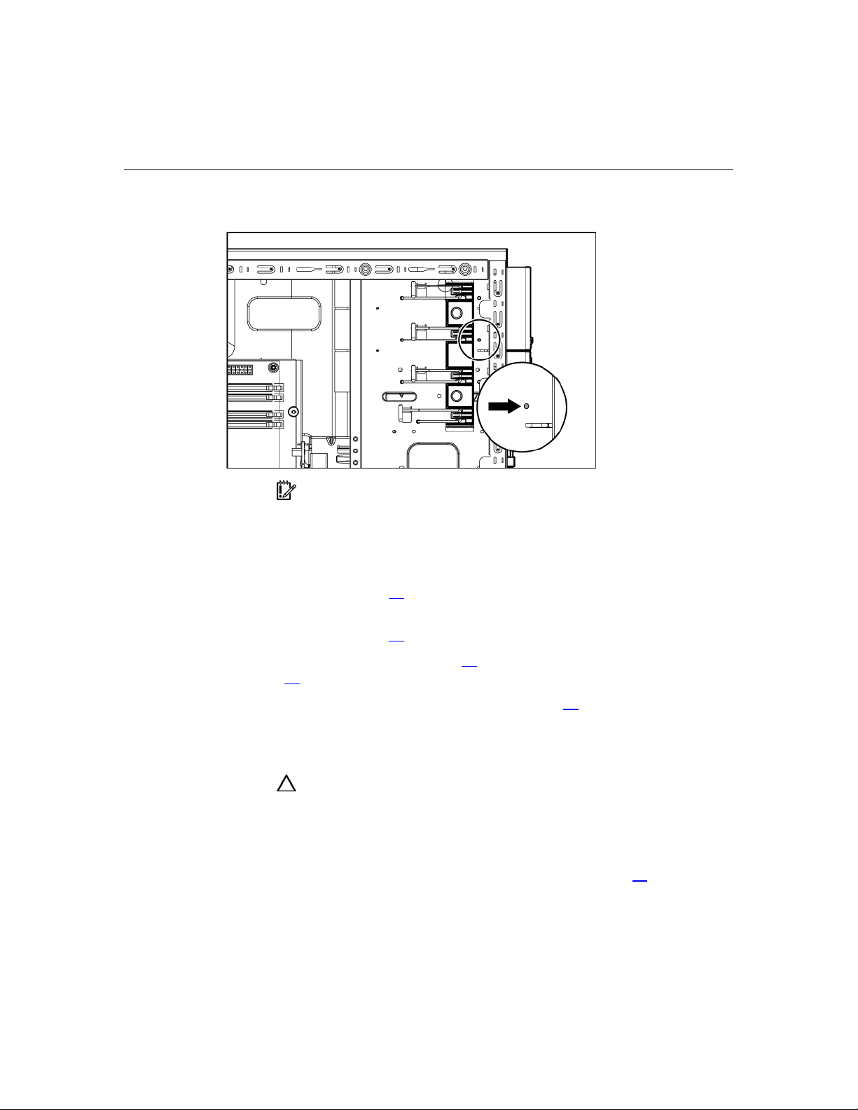
Removal and replacement procedures 33
5. Use a screwdriver to disengage the two wire supports inside the full-height
drive bays.
6. Install the tape drive.
34 HP ProLiant ML310 Generation 2 Server Maintenance and Service Guide
7. Install the retaining screw.
IMPORTANT: HP recommends installing the tape drive on a
separate SCSI cable to avoid a decrease in performance on other SCSI
devices.
8. Connect the data and power cables to the back of the tape drive.
9. Connect the data cable into a SCSI controller channel ("System board
components" on page 57
10. Remove the applicable bezel blanks from the bezel ("Front panel
components" on page 53
11. Install the bezel ("Bezel" on page 17
page 12
12. Replace the access panel ("Access panel" on page 20
).
Full-height tape drive
CAUTION: To prevent improper cooling and thermal damage, do
not operate the server unless all bays are populated with either a
component or a blank.
To remove the component:
1. Power down the server ("Powering down the server" on page 15
).
).
, "Server warnings and cautions" on
).
).

Removal and replacement procedures 35
2. Remove the bezel ("Bezel" on page 17).
3. Remove the access panel ("Access panel" on page 20
4. Disconnect the power and data cables.
5. Remove the tape drive.
To replace the component, reverse the removal procedure.
Power button/LED board
).
To remove the component:
1. Power down the server ("Powering down the server" on page 15
2. Remove the bezel ("Bezel" on page 17
3. Remove the access panel ("Access panel" on page 20
).
).
).
4. Disconnect the power and data cables.

36 HP ProLiant ML310 Generation 2 Server Maintenance and Service Guide
5. Remove the front panel assembly.
6. Remove the power button/LED board.
To replace the component, reverse the removal procedure.

Removal and replacement procedures 37
Hard drive (non-hot-plug)
This procedure applies to non hot-plug drives only. If the server is equipped with
hot-plug hard drives, refer to the hot-plug hard drive removal procedures ("Hotplug SATA/SAS hard drive" on page 18
17
).
To remove the component:
, "Hot-plug SCSI hard drive" on page
1. Power down the server ("Powering down the server" on page 15
2. Remove the bezel ("Bezel" on page 17
3. Remove the access panel ("Access panel" on page 20
4. Disconnect the power and data cables.
5. Remove the hard drive cage.
).
).
).

38 HP ProLiant ML310 Generation 2 Server Maintenance and Service Guide
6. Remove the hard drive.
To replace the component, reverse the removal procedure.
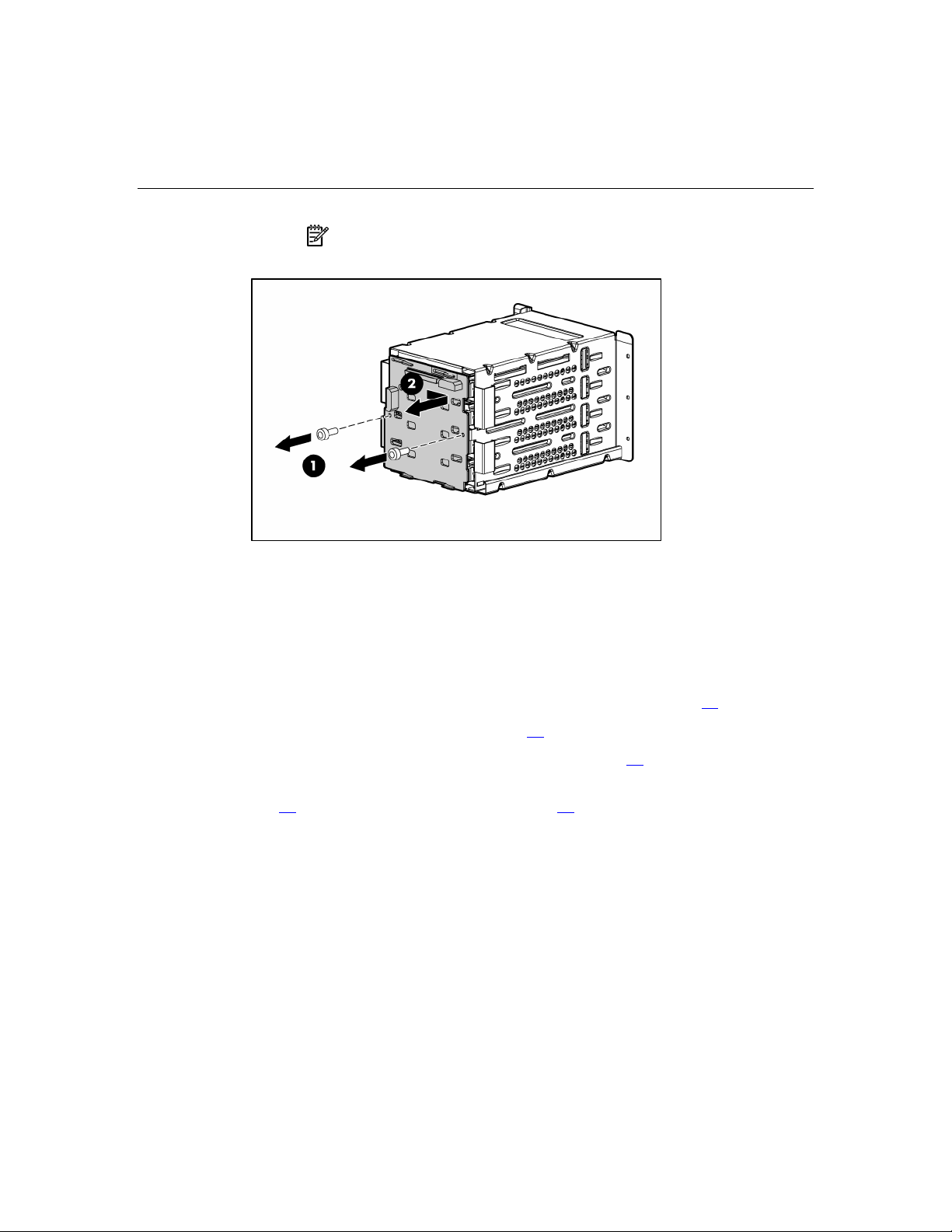
Hot-plug SCSI backplane
To remove the component:
1. Power down the server ("Powering down the server" on page 15
2. Remove the bezel ("Bezel" on page 17
3. Remove the access panel ("Access panel" on page 20
).
).
).
4. Remove all hot-plug hard drives ("Hot-plug SATA/SAS hard drive" on page
, "Hot-plug SCSI hard drive" on page 17).
18
5. Disconnect the power and data cables.

Removal and replacement procedures 39
6. Remove the hard drive cage.
7. Remove the SCSI backplane.
40 HP ProLiant ML310 Generation 2 Server Maintenance and Service Guide
NOTE: If replacing only the hard drive cage, retain the backplane
for use with the replacement hard drive cage.
To replace the component, reverse the removal procedure.
Hot-plug SATA or SAS backplane
To remove the component:
1. Power down the server ("Powering down the server" on page 15
2. Remove the bezel ("Bezel" on page 17
3. Remove the access panel ("Access panel" on page 20
).
).
).
4. Remove all hot-plug hard drives ("Hot-plug SATA/SAS hard drive" on page
, "Hot-plug SCSI hard drive" on page 17).
18
5. Disconnect the power and data cables.

Removal and replacement procedures 41
6. Remove the hard drive cage.
7. Remove the SATA or SAS backplane.

42 HP ProLiant ML310 Generation 2 Server Maintenance and Service Guide
NOTE: If replacing only the hard drive cage, retain the backplane
for use with the replacement hard drive cage.
To replace the component, reverse the removal procedure.
System board
To remove the component:
1. Power down the server ("Powering down the server" on page 15
2. Remove the bezel ("Bezel" on page 17
3. Remove the access panel ("Access panel" on page 20
4. Remove the air baffle ("Air baffle" on page 25
).
).
).
).
5. Disconnect all cabling.

Removal and replacement procedures 43
6. Remove the system board.
To replace the component, reverse the removal procedure.
After you replace the system board, you must re-enter the server serial number
and the product ID.
1. During the server startup sequence, press the F9 key to access RBSU.
2. Select the Advanced Options menu.
3. Select Serial Number. The following warning is displayed:
Warning: The serial number should ONLY be modified by
qualified service personnel. This value should always
match the serial number located on the chassis.
4. Press the Enter key to clear the warning.
5. Enter the serial number.
6. Select Product ID. The following warning is displayed.
Warning: The Product ID should ONLY be modified by
qualified service personnel. This value should always
match the Product ID located on the chassis.
7. Enter the product ID and press the Enter key.
8. Press the Esc key to close the menu.
9. Press the Esc key to exit RBSU.

44 HP ProLiant ML310 Generation 2 Server Maintenance and Service Guide
10. Press the F10 key to confirm exiting RBSU. The server will automatically
reboot.

45
Server cabling
In this section
Hot-plug SCSI cabling..................................................................................................................45
Hot-plug SATA cabling................................................................................................................46
Non-hot-plug SCSI cabling ..........................................................................................................46
Non-hot-plug SATA cabling ........................................................................................................47
SAS cabling..................................................................................................................................48
Hot-plug SCSI cabling
Item Cable description
1 Power cable
2 SCSI cable

46 HP ProLiant ML310 Generation 2 Server Maintenance and Service Guide
Hot-plug SATA cabling
Item Cable description
1 Power cable
2 SATA cable
Non-hot-plug SCSI cabling

Server cabling 47
Item Cable description
1 SCSI cable
2 Power cable
Non-hot-plug SATA cabling
Item Cable description
1 SATA cable
2 Power cable

48 HP ProLiant ML310 Generation 2 Server Maintenance and Service Guide
SAS cabling
Item Cable description
1 Power cable
2 SAS cable

49
Diagnostic tools
In this section
Survey Utility ...............................................................................................................................49
Array Diagnostic Utility ...............................................................................................................49
HP Insight Diagnostics .................................................................................................................50
Integrated Management Log.........................................................................................................50
Survey Utility
Survey Utility, a feature within HP Insight Diagnostics ("Array Diagnostic
Utility" on page 49
information on ProLiant servers.
This utility supports operating systems that may not be supported by the server.
For operating systems supported by the server, refer to the HP website
(http://www.hp.com/go/supportos
, on page 50), gathers critical hardware and software
).
If a significant change occurs between data-gathering intervals, the Survey
Utility marks the previous information and overwrites the Survey text files to
reflect the latest changes in the configuration.
Survey Utility is installed with every SmartStart-assisted installation or can be
installed through the HP PSP.
Array Diagnostic Utility
ADU is tool that collects information about array controllers and generates a list
of detected problems. ADU can be accessed from the SmartStart CD or
downloaded from the HP website (http://www.hp.com
).

50 HP ProLiant ML310 Generation 2 Server Maintenance and Service Guide
HP Insight Diagnostics
HP Insight Diagnostics is a proactive server management tool, available in both
offline and online versions, that provides diagnostics and troubleshooting
capabilities to assist IT administrators who verify server installations,
troubleshoot problems, and perform repair validation.
HP Insight Diagnostics Offline Edition performs various in-depth system and
component testing while the OS is not running. To run this utility, launch the
SmartStart CD.
HP Insight Diagnostics Online Edition is a web-based application that captures
system configuration and other related data needed for effective server
management. Available in Microsoft® Windows® and Linux versions, the utility
helps to ensure proper system operation.
For more information or to download the utility, refer to the HP website
(http://www.hp.com/servers/diags
).
Integrated Management Log
The IML records hundreds of events and stores them in an easy-to-view form.
The IML timestamps each event with 1-minute granularity.
You can view recorded events in the IML in several ways, including the
following:
• From within HP SIM ("HP Insight Diagnostics" on page 50
• From within Survey Utility (on page 49
• From within operating system-specific IML viewers
– For NetWare: IML Viewer
– For Windows®: IML Viewer
– For Linux: IML Viewer Application
• From within HP Insight Diagnostics ("Array Diagnostic Utility" on page 49
on page 50
)
)
)
,

Diagnostic tools 51
For more information, refer to the Management CD in the HP ProLiant Essentials
Foundation Pack.


53
Server component identification
In this section
Front panel components................................................................................................................53
Front panel LEDs and buttons......................................................................................................54
Rear panel components.................................................................................................................55
Rear panel LEDs and buttons .......................................................................................................56
System board components............................................................................................................57
System board LEDs......................................................................................................................59
System LEDs and internal health LED combinations ..................................................................60
SCSI IDs.......................................................................................................................................62
Hot-plug SCSI hard drive LEDs...................................................................................................62
Hot-plug SCSI hard drive LED combinations..............................................................................63
Hot-plug SATA or SAS IDs.........................................................................................................64
SATA or SAS hard drive LEDs ...................................................................................................65
Fan locations.................................................................................................................................66
Front panel components

54 HP ProLiant ML310 Generation 2 Server Maintenance and Service Guide
Item Description
1 Media bays (bezel blanks)
2 Power On/Standby button
3 Hard drive bays
4 USB connectors (2)
5 Bezel lock
6 CD-ROM drive
Front panel LEDs and buttons
Item Description Status
1 CD-ROM drive ejector
button
2 Power On/Standby button N/A
3 Power on/Standby LED Amber = System has AC power and is in standby mode
N/A
Green = System has AC power and is functioning
Off = System has no AC power

Server component identification 55
Item Description Status
4 Hard drive activity LED (for
non-hot-plug)
Green = Hard drives are properly connected and functioning
Off = No hard drive activity
5 NIC link/activity LED Green = Linked to network
Flashing green = Linked with activity on the network
Off = No network connection
6 Internal system health
LED
Green = Normal (system on)
Amber = System health is degraded
Red = System health is critical
Off = Normal (system off)
7 CD-ROM drive indicator
N/A
LED
Rear panel components
Item Description
1 Power cord connector
2 Mouse connector
3 Keyboard connector

56 HP ProLiant ML310 Generation 2 Server Maintenance and Service Guide
Item Description
4 Serial connector
5 Video connector
6 USB connectors (2)
7 RJ-45 Ethernet connector
8 Parallel connector
Rear panel LEDs and buttons
Item Description Status
1 10/100/1000 NIC link LED On = Link
Off = No link
2 10/100/1000 NIC standby LED Flashing =
Activity
Off = No activity

Server component identification 57
System board components
Item Description Item Description
1 Mouse/keyboard connectors 10 Diskette drive connector
2 Processor power connector 11 RILOE connector
3 Power supply connector 12 32-bit PCI slot
4 DIMM slot 4 (B) 13 PCI Express x4 slot *
5 DIMM slot 3 (B) 14 PCI-X slot 2
6 DIMM slot 2 (A) 15 PCI-X slot 1
7 DIMM slot 1 (A) 16 RJ-45 connector
8 IDE connector 17 USB connectors (2)
9 SATA connector 18 Serial/video/parallel ports
* x8 PCI Express cards are supported, but will run at x4 speeds.
System maintenance switch
Position Default Function
S1 Off Reserved

58 HP ProLiant ML310 Generation 2 Server Maintenance and Service Guide
Position Default Function
S2 Off Off = System configuration can
be changed
On = System configuration is
locked
S3 Off Reserved
S4 Off Reserved
S5 Off Off = No function
On = Clears power-on password
and administrator password
S6 Off Off = Normal
On = ROM treats system
configuration as invalid
When the system maintenance switch position 6 is set to the On position, the
system is prepared to erase all system configuration settings from both CMOS
and NVRAM.
CAUTION: Clearing CMOS and/or NVRAM deletes configuration
information. Be sure to properly configure the server or data loss could
occur.

Server component identification 59
System board LEDs
Item LED description Status
1 PPM failure Off = Normal
Amber = PPM failed or missing
2 Multibit error Off = Normal
Amber = A multibit error has occurred
3 Single bit error Off = Normal
Amber = Single bit error limit has been
exceeded
4 DIMM 4 failure Off = Normal
Amber = DIMM 4 has failed or is missing
5 DIMM 3 failure Off = Normal
Amber = DIMM 3 has failed or is missing
6 DIMM 2 failure Off = Normal
Amber = DIMM 2 has failed or is missing
7 DIMM 1 failure Off = Normal
Amber = DIMM 1 has failed or is missing

60 HP ProLiant ML310 Generation 2 Server Maintenance and Service Guide
Item LED description Status
8 Power good Off = Normal
Green = Power failed
9 Processor failure Off = Normal
Amber = Processor has failed
10 System temperature
alert
11 System fan failure Off = Normal
12 Processor fan failure Off = Normal
Off = Normal
Amber = System temperature has exceeded
OS cautionary level
Amber = System fan has failed or is missing
Amber = Processor fan has failed or is missing
System LEDs and internal health LED combinations
When the internal health LED on the front panel illuminates either amber or red,
the server is experiencing a health event. Combinations of illuminated system
LEDs and the internal health LED indicate system status.
NOTE: The system management driver must be installed in order
for the internal health LED to provide pre-failure and warranty
conditions.
The front panel health LEDs indicate only the current hardware status. In some
situations, HP SIM may report server status differently than the health LEDs
because the software tracks more system attributes.
System LED and
color
Internal health
LED color
Status
Processor failure,
socket X (Amber)
Amber Processor in socket X is in a pre-failure condition.
Red One or more of the following conditions may exist:
• Processor in socket X has failed.
• Processor X is not installed in the socket.
• ROM detected a failed processor during POST.

Server component identification 61
System LED and
color
PPM failure, slot X
(Amber)
Internal health
Status
LED color
Red • PPM in slot X has failed.
• PPM is not installed in slot X, but the corresponding
processor is installed.
DIMM failure, slot X
(Amber)
Red • DIMM in slot X has failed.
• DIMM has experienced a multi-bit error.
Amber • DIMM in slot X has reached single-bit correctable
error threshold.
• DIMM in slot X is in a pre-failure condition.
DIMM bank error (all
slots in one bank,
Red The bank is not populated entirely or DIMMs do not all
match within the bank.
Amber)
DIMM failure (all
slots, Amber)
System temperature
alert (Amber)
Red • No valid or usable memory is installed in the system.
• The banks are not populated in the correct order.
Red System temperature has exceeded OS cautionary level
or critical hardware level.
Fan (Amber) Red A required fan has failed.
Power supply
Amber A redundant fan has failed.
Red The power supply backplane has failed.
backplane failure
(Amber)

62 HP ProLiant ML310 Generation 2 Server Maintenance and Service Guide
SCSI IDs
Hot-plug SCSI hard drive LEDs

Server component identification 63
Item LED description Status
1 Activity status On = Drive activity
Flashing = High activity on the drive or
drive is being configured as part of an
array.
Off = No drive activity
2 Online status On = Drive is part of an array and is
currently working.
Flashing = Drive is actively online.
Off = Drive is offline.
3 Fault status On = Drive failure
Flashing = Fault-process activity
Off = No fault-process activity
Hot-plug SCSI hard drive LED combinations
Activity
LED (1)
Online
LED (2)
Fault LED
(3)
Interpretation
On, off, or
On or off Flashing A predictive failure alert has been received for this drive.
flashing
On, off, or
On Off The drive is online and is configured as part of an array.
flashing
On or
Flashing Off
flashing
On Off Off
Replace the drive as soon as possible.
If the array is configured for fault tolerance and all other drives in
the array are online, and a predictive failure alert is received or a
drive capacity upgrade is in progress, you may replace the drive
online.
Do not remove the drive. Removing a drive may terminate the
current operation and cause data loss.
The drive is rebuilding or undergoing capacity expansion.
Do not remove the drive.
The drive is being accessed, but (1) it is not configured as part of an
array; (2) it is a replacement drive and rebuild has not yet started; or
(3) it is spinning up during the POST sequence.

64 HP ProLiant ML310 Generation 2 Server Maintenance and Service Guide
Activity
LED (1)
Flashing Flashing Flashing
Online
LED (2)
Fault LED
(3)
Interpretation
Do not remove the drive. Removing a drive may cause data
loss in non-fault-tolerant configurations.
Either (1) the drive is part of an array being selected by an array
configuration utility; (2) Drive Identification has been selected in
HP SIM; or (3) drive firmware is being updated.
Off Off On The drive has failed and has been placed offline.
You may replace the drive.
Off Off Off Either (1) the drive is not configured as part of an array; (2) the
drive is configured as part of an array, but it is a replacement drive
that is not being accessed or being rebuilt yet; or (3) the drive is
configured as an online spare.
If the drive is connected to an array controller, you may replace the
drive online.
Hot-plug SATA or SAS IDs

Server component identification 65
SATA or SAS hard drive LEDs
Item LED description Status
1 Fault/UID status Amber = Drive failure
Flashing amber = Fault-process activity
Blue = Unit identification is active
Off = No fault-process activity
2 Online/Activity status Green = Drive activity
Flashing green = High activity on the
drive or drive is being configured as part
of an array
Off = No drive activity
IMPORTANT: When hot-plug SATA hard drives are installed,
SATA LED functionality and full SATA hot-plug capability are not
supported with the embedded controller. For full LED and hot-plug
support, an optional SATA RAID or SAS controller must be installed.

66 HP ProLiant ML310 Generation 2 Server Maintenance and Service Guide
Fan locations
Item Description
1 System fan
2 Processor fan

67
Specifications
In this section
Server specifications.....................................................................................................................67
Environmental specifications .......................................................................................................68
Hot-plug power supply calculations.............................................................................................68
1.44-MB diskette drive specifications ..........................................................................................68
CD-ROM drive specifications......................................................................................................69
Server specifications
Specification Value
Dimensions
Height 43 cm (16.93 in)
Depth (w/o bezel) 50 cm (19.69 in)
Depth (w bezel) 54 cm (21.26 in)
Width 20 cm (7.87 in)
Weight (maximum) 22 kg (47.41 lb)
Weight (no drives installed) 16.5 kg (36.24 lb)
Input Requirements
Rated input voltage 100 VAC to 240 VAC *
Rated input frequency 47 Hz to 63 Hz
Rated input current 10 A (100 V) to 5 A (200 V)
Rated input power 1000 W
BTUs per hour 2730
Power Supply Output
Rated steady-state power 320 W
Maximum peak power 350 W

68 HP ProLiant ML310 Generation 2 Server Maintenance and Service Guide
*10 A is required for 100 to 127 VAC; 5 A is required for 200 to 240 VAC.
Environmental specifications
Specification Value
Temperature range*
Operating
Shipping
Maximum wet bulb temperature
Relative humidity
(noncondensing)**
10°C to 35°C (50°F to 95°F)
-10°C to 60°C (14°F to 140°F)
28°C (82.4°F)
Operating 20% to 80%
Non-operating 20% to 90%
* All temperature ratings shown are for sea level. An altitude derating of 1°C per 300 m
(1.8°F per 1,000 ft) to 3048 m (10,000 ft) is applicable. No direct sunlight allowed.
** Storage maximum humidity of 95% is based on a maximum temperature of 45°C
(113°F). Altitude maximum for storage corresponds to a pressure minimum of 70 KPa.
Hot-plug power supply calculations
For power supply specifications and calculators to determine electrical and heat
loading for the server, refer to the HP Enterprise Configurator website
(http://h30099.www3.hp.com/configurator/
).
1.44-MB diskette drive specifications
Specification Value
Dimensions
Height 12.7 mm (0.5 in)
Width 96 mm (3.8 in)

Specifications 69
Specification Value
Depth 130 mm (5.1 in)
LEDs (front panel) Green = On
Read/write capacity per
diskette
High density 1.44 MB
Low density 720 KB
Drives supported 1
Drive height One-third height
Drive rotation 300 rpm
Transfer rate
High 500 Kb/s
Low 250 Kb/s
Bytes/sector 512
Sectors per track (high/low) 18/9
Tracks per side (high/low) 80/80
Access times
Track-to-track (high/low) 3 ms/6 ms
Average (high/low) 169 ms/94 ms
Setting time 15 ms
Latency average 100 ms
Cylinders (high/low) 80/80
Read/write heads 2
CD-ROM drive specifications
Specification Value
Disk formats CD-ROM (modes 1 and 2); mixed mode (audio and data combined); CD-DA;
Photo CD (single/multiple-session), CD-XA ready; CDi ready

70 HP ProLiant ML310 Generation 2 Server Maintenance and Service Guide
Specification Value
Capacity 550 MB (mode 1, 12 cm)
Block size 2368, 2352 bytes (mode 0)
Dimensions
Height 12.7 mm (0.50 in)
Depth 132.08 mm (5.20 in)
Width 132.08 mm (5.20 in)
Weight 0.34 kg (0.75 lb)
Data transfer rate
Sustained 150 KB/s (sustained 1X), 1500/3600 KB/s (10X to 24X)
Burst 16.6 MB/s
Access times
(typical)
Full stroke 300 ms
Random 140 ms
Diameter 12 cm, 8 cm (4.70 in, 3.15 in)
Thickness 1.2 mm (0.05 in)
640 MB (mode 2, 12 cm)
2352, 2340, 2336, 2048 bytes (mode 1)
2352, 2340, 2336, 2048 bytes (mode 2)
Track pitch 1.6 µm (6.3 × 10⁻⁷ in)
Cache/buffer 128 KB
Startup time < 10 s
Stop time < 5 s (single); < 30 s (multisession)
Laser parameters
Type Semiconductor laser GaAs
Wave length 700 ± 25 nm
Divergence angle 53.5° ± 1.5°
Output power 0.14 mW

Specifications 71
Specification Value
Operating conditions
Temperature 5°C to 45°C (41°F to 118°F)
Humidity 5% to 90%


73
Acronyms and abbreviations
ABEND
abnormal end
ACU
Array Configuration Utility
ASR
Automatic Server Recovery
DDR
double data rate
DIMM
dual inline memory module
ECC
error checking and correcting
HBA
host bus adapter
IEC
International Electrotechnical Commission

74 HP ProLiant ML310 Generation 2 Server Maintenance and Service Guide
iLO
Integrated Lights-Out
IML
Integrated Management Log
IPL
initial program load
IRQ
interrupt request
LDAP
Lightweight Directory Access Protocol
MPS
multi-processor specification
NEMA
National Electrical Manufacturers Association
NFPA
National Fire Protection Association
NIC
network interface controller
NMI
non-maskable interrupt

Acronyms and abbreviations 75
NVRAM
non-volatile memory
PCI-X
peripheral component interconnect extended
PDU
power distribution unit
POST
Power-On Self Test
PPM
Processor Power Module
PSP
ProLiant Support Pack
PXE
preboot eXecution environment
RAID
redundant array of inexpensive (or independent) disks
RBSU
ROM-Based Setup Utility
RILOE II
Remote Insight Lights-Out Edition II

76 HP ProLiant ML310 Generation 2 Server Maintenance and Service Guide
SAS
serial attached SCSI
SATA
serial ATA
SCSI
small computer system interface
SDRAM
synchronous dynamic RAM
SIM
Systems Insight Manager
TMRA
recommended ambient operating temperature
UID
unit identification
VHDCI
very high density cable interconnect
WOL
Wake-on LAN

77
expansion slots 55
Index
F
fan assembly 25
A
AC power supply 27, 56
access panel 20
ADU (Array Diagnostic Utility) 49
air baffle 25
ASR (Automatic Server Recovery) 73
Automatic Server Recovery (ASR) 73
fan LED 62
fan zones 63
fans 25, 66
fans, replacing 25
front panel components 53
front panel LEDs 54
H
B
battery 21
bezel, removing 17
buttons 53
C
cabling 45, 46, 47, 48
CD-ROM drive 31, 69
components 53
connectors 53
CSR (customer self repair) 5
customer self repair 5
D
DC power supply 56
diagnostic tools 49, 50
diagnostics utility 50
DIMM slot locations 57
DIMMs 23
diskette drive 30, 68
drive LEDs 62, 63
DVD-ROM drive 31
E
electrostatic discharge 12
expansion boards 21
hard drive LEDs 62, 63
hard drive, replacing 17, 18, 37
hard drives 62, 63
hard drives, determining status of 62, 63
hard drives, removing 17, 18, 37
health LEDs 62
HP Insight Diagnostics 50
I
illustrated parts catalog 5
iLO (Integrated Lights-Out) 55
IML (Integrated Management Log) 50
Insight Diagnostics 50
K
keyboard connector 55
L
LEDs 53, 62, 63
LEDs, hard drive 62, 63
M
management tools 49
memory slot LEDs 60
memory slots 57
mouse connector 55

78 HP ProLiant ML310 Generation 2 Server Maintenance and Service Guide
N
network connector LEDs 56
NIC (network interface controller) 74
NIC LEDs 60
O
overtemperature LED 60, 63
P
parallel connector 55
power button/LED board 35
power cord connector 55
power supplies 27, 55, 56
power supply LEDs 56, 60
powering down 15
PPM failure LEDs 60, 63
preparation procedures 15
processor failure LEDs 60
processor fan assembly, removing 27
processor module 27
R
rear panel components 55
rear panel connectors 55
rear panel LEDs 56
RJ-45 connectors 55
RJ-45 network connector LEDs 56
specifications 67, 68
specifications, environmental 68
specifications, server 67
static electricity 12
Survey Utility 49
switches 57
system board 42, 57, 59
system board battery 21
system board LEDs 59
T
temperature, overtemperature LED 60, 63
tools 49, 55
U
UID LEDs 55, 56
USB connectors 55
utilities 49, 50
V
video connector 55
W
warnings 12, 13
S
safety considerations 12
SAS backplane 40
SAS cabling 48
SAS hard drive cabling 48
SAS-SATA hard drive cage 40
SATA backplane 40
SATA drives 64
SCSI backplane 38
serial connector 55
serial number 55
spare part numbers 6, 7
 Loading...