

Page 1

HP ProLiant DL580 Generation 2 Server
Maintenance and Service Guide
January 2004 (Fifth Edition)
Part Number 230828-005
Page 2

© Copyright 2003 Hewlett-Packard Development Company, L.P.
The information contained herein is subject to change without notice. The only warranties for HP products and
services are set forth in the express warranty statements accompanying such products and services. Nothing herein
should be construed as constituting an additional warranty. HP shall not be liable for technical or editorial errors
or omissions contained herein.
Microsoft, Windows, and Windows NT are U.S. registered trademarks of Microsoft Corporation. Intel, Pentium,
and Itanium are trademarks or registered trademarks of Intel Corporation or its subsidiaries in the United States
and other countries. UNIX is a registered trademark of The Open Group. Linux is a U.S. registered trademark of
Linus Torvalds.
HP ProLiant DL580 Generation 2 Server Maintenance and Service Guide
January 2004 (Fifth Edition)
Part Number 230828-005
Page 3

Contents
About This Guide
Audience Assumptions.................................................................................................................................ix
Technician Notes..........................................................................................................................................ix
Where to Go for Additional Help..................................................................................................................x
Integrated Management Log...................................................................................................................x
Telephone Numbers................................................................................................................................x
Chapter 1
Illustrated Parts Catalog
Mechanical Components Exploded View ................................................................................................. 1-2
Mechanical Components Spare Parts List................................................................................................. 1-3
System Components Exploded View ........................................................................................................ 1-4
System Components Spare Parts List........................................................................................................ 1-5
Chapter 2
Removal and Replacement Procedures
Safety Considerations................................................................................................................................ 2-1
Electrostatic Discharge ....................................................................................................................... 2-1
Symbols on Equipment....................................................................................................................... 2-2
Rack Warnings and Cautions.............................................................................................................. 2-2
Server Warnings and Cautions............................................................................................................ 2-3
Preparation Procedures.............................................................................................................................. 2-4
Locating and Removing the Torx T-15 Tool...................................................................................... 2-5
Extending the Server from the Rack................................................................................................... 2-6
Opening and Removing the Rear Access Panel.................................................................................. 2-8
Removing the Front Access Panel .................................................................................................... 2-10
Replacing the Access Panels............................................................................................................. 2-11
Powering Down the Server ............................................................................................................... 2-13
Removing the Server from the Rack................................................................................................. 2-13
Memory ................................................................................................................................................... 2-15
Memory Replacement Guidelines..................................................................................................... 2-15
Memory Board Slot Locations.......................................................................................................... 2-16
Parts of the Memory Board............................................................................................................... 2-17
Memory Board LEDs and Icons ....................................................................................................... 2-18
DIMM Installation Requirements..................................................................................................... 2-22
Removing a Memory Board.............................................................................................................. 2-23
Removing a DIMM........................................................................................................................... 2-25
Installing a DIMM ............................................................................................................................ 2-26
HP ProLiant DL580 Generation 2 Server Maintenance and Service Guide iii
Page 4

Contents
Installing a Memory Board................................................................................................................2-27
Configuring the Memory...................................................................................................................2-28
Hot-Plug Procedures ................................................................................................................................2-30
Hard Drive Blanks.............................................................................................................................2-30
Hot-Plug SCSI Hard Drives ..............................................................................................................2-31
Power Supply Blank..........................................................................................................................2-33
Hot-Plug Power Supplies ..................................................................................................................2-34
PCI and PCI-X Hot Plug Expansion Boards .....................................................................................2-35
Performance Balancing .....................................................................................................................2-39
Hot-Plug Fans....................................................................................................................................2-40
Non-Hot-Plug Procedures........................................................................................................................2-41
Slimline Drives..................................................................................................................................2-42
Front Bezel ........................................................................................................................................2-43
Power Button/LED assembly ............................................................................................................2-45
Processor Air Baffle ..........................................................................................................................2-46
Processor Power Modules .................................................................................................................2-47
Processors..........................................................................................................................................2-49
Non-Hot-Plug PCI-X Expansion Boards...........................................................................................2-51
PCI-X Expansion Board Basket ........................................................................................................2-53
PCI-X Hot Plug Board ......................................................................................................................2-54
SCSI Cables.......................................................................................................................................2-55
Front Fan Cage ..................................................................................................................................2-56
Pass-Through Board..........................................................................................................................2-57
Diagnostics Display Board and Lightpipe.........................................................................................2-58
Rear Fan Cage ...................................................................................................................................2-59
Battery-Backed Write Cache Assembly............................................................................................2-60
SCSI Backplane.................................................................................................................................2-62
System Battery ..................................................................................................................................2-63
System Board ....................................................................................................................................2-65
AC Filter Cable Assembly.................................................................................................................2-68
Re-entering the Server Serial Number.....................................................................................................2-71
Chapter 3
Diagnostic Tools
Chapter 4
Connectors, LEDs, and Switches
Connectors .................................................................................................................................................4-1
Rear Panel............................................................................................................................................4-2
System Board ......................................................................................................................................4-3
SCSI Backplane Board........................................................................................................................4-4
Memory Board ....................................................................................................................................4-5
LEDs ..........................................................................................................................................................4-6
Front Panel ..........................................................................................................................................4-7
QuickFind Diagnostic Display ............................................................................................................4-8
Interlock Status....................................................................................................................................4-9
Hot-Plug SCSI Hard Drive................................................................................................................4-10
Hot-Plug Fan .....................................................................................................................................4-12
Hot-Plug Power Supplies ..................................................................................................................4-13
iv HP ProLiant DL580 Generation 2 Server Maintenance and Service Guide
Page 5

PCI-X Hot Plug................................................................................................................................. 4-14
Network Interface Controller............................................................................................................ 4-15
Battery-Backed Write Cache Enabler ..................................................................................................... 4-17
Memory Board.................................................................................................................................. 4-18
Internal Diagnostic Display .............................................................................................................. 4-22
System Board Switches........................................................................................................................... 4-23
System Maintenance Switch (SW4) .................................................................................................4-24
System ID Switch (SW7).................................................................................................................. 4-26
iLO/Spread Spectrum Switch (SW8)................................................................................................4-27
Non-Maskable Interrupt (NMI) Switch ............................................................................................ 4-28
Rear Unit Identification LED Switch...................................................................................................... 4-29
NC7770 PCI-X Gigabit Server Adapter Jumper ..................................................................................... 4-30
Chapter 5
Troubleshooting
When the Server Does Not Start ............................................................................................................... 5-2
Diagnostic Steps........................................................................................................................................ 5-4
Problems After Initial Boot ....................................................................................................................... 5-9
ROMPaq Disaster Recovery.................................................................................................................... 5-11
Other Information Resources .................................................................................................................. 5-12
Contents
Chapter 6
Specifications
Index
List of Figures
1-1 Mechanical components exploded view ............................................................................................. 1-2
1-2 System components exploded view .................................................................................................... 1-4
2-1 Locating and removing the Torx T-15 tool......................................................................................... 2-5
2-2 Loosening the front panel thumbscrews ............................................................................................. 2-6
2-3 Extending the server from the rack..................................................................................................... 2-6
2-4 Returning the server back into the rack .............................................................................................. 2-7
2-5 Unlocking and sliding the rear access panel open .............................................................................. 2-8
2-6 Opening the rear access panel............................................................................................................. 2-9
2-7 Removing the rear access panel.......................................................................................................... 2-9
2-8 Removing the front access panel ...................................................................................................... 2-10
2-9 Replacing the front access panel....................................................................................................... 2-11
2-10 Lining up the guide marks ................................................................................................................ 2-12
2-11 Installing the rear access panel ......................................................................................................... 2-12
2-12 Removing the server from the rack................................................................................................... 2-14
2-13 Memory board slots .......................................................................................................................... 2-16
2-14 Parts of the memory board................................................................................................................ 2-17
2-15 Memory board LEDs and icons ........................................................................................................ 2-18
2-16 Removing a memory board............................................................................................................... 2-24
2-17 Removing a DIMM........................................................................................................................... 2-25
2-18 Installing a DIMM ............................................................................................................................ 2-26
2-19 Installing a memory board ................................................................................................................ 2-27
HP ProLiant DL580 Generation 2 Server Maintenance and Service Guide v
Page 6

Contents
2-20 Removing a drive blank ....................................................................................................................2-30
2-21 Removing a hot-plug SCSI hard drive ..............................................................................................2-32
2-22 Removing a power supply blank .......................................................................................................2-33
2-23 Removing a hot-plug power supply ..................................................................................................2-34
2-24 PCI-X slot locations ..........................................................................................................................2-36
2-25 PCI-X Hot Plug button......................................................................................................................2-37
2-26 Pressing the PCI-X retaining clip......................................................................................................2-37
2-27 Removing a PCI-X Hot Plug expansion board..................................................................................2-38
2-28 Removing a hot-plug fan...................................................................................................................2-40
2-29 Removing a drive from a slimline drive bay .....................................................................................2-42
2-30 Removing the exterior and interior chassis screws ...........................................................................2-43
2-31 Disengaging the locking tabs and removing the front bezel .............................................................2-44
2-32 Removing the power button/LED assembly......................................................................................2-45
2-33 Removing the processor air baffle.....................................................................................................2-46
2-34 Opening the processor retaining bracket ...........................................................................................2-47
2-35 Removing a PPM...............................................................................................................................2-48
2-36 Opening the processor retaining bracket ...........................................................................................2-49
2-37 Removing the processor/heatsink assembly......................................................................................2-50
2-38 Pressing the PCI-X retaining clip......................................................................................................2-51
2-39 Removing an expansion board from a non-hot-plug slot ..................................................................2-52
2-40 Removing the expansion board basket..............................................................................................2-53
2-41 Removing the PCI-X Hot Plug board................................................................................................2-54
2-42 Disconnecting SCSI cables from the backplane and expansion boards ............................................2-55
2-43 Removing the front fan cage .............................................................................................................2-56
2-44 Removing the pass-through board.....................................................................................................2-57
2-45 Removing the removable media board..............................................................................................2-58
2-46 Removing the rear fan cage...............................................................................................................2-59
2-47 Removing the BBWC enabler and 5i Plus Memory Module ............................................................2-61
2-48 Removing the SCSI backplane..........................................................................................................2-62
2-49 Locating the battery on the system board..........................................................................................2-63
2-50 Removing the battery from the system board....................................................................................2-64
2-51 Unscrewing the thumbscrews and sliding the system board .............................................................2-66
2-52 Removing the system board from the chassis ...................................................................................2-67
2-53 Cutting the cable tie-wraps................................................................................................................2-69
2-54 Removing the cable clips...................................................................................................................2-69
2-55 Removing the power supply connectors............................................................................................2-70
2-56 Removing the AC filters....................................................................................................................2-70
4-1 Rear panel components .......................................................................................................................4-2
4-2 System board connectors.....................................................................................................................4-3
4-3 SCSI backplane board connectors.......................................................................................................4-4
4-4 Memory board connectors and DIMM banks......................................................................................4-5
4-5 Front panel LEDs ................................................................................................................................4-7
4-6 QuickFind Diagnostic Display LEDs..................................................................................................4-8
4-7 Interlock LEDs ....................................................................................................................................4-9
4-8 Hot-plug SCSI hard drive LEDs........................................................................................................4-10
4-9 Hot-plug fan LED..............................................................................................................................4-12
4-10 Hot-plug power supply LEDs............................................................................................................4-13
4-11 External PCI-X Hot Plug LEDs ........................................................................................................4-14
4-12 Network Interface Controller LEDs ..................................................................................................4-15
vi HP ProLiant DL580 Generation 2 Server Maintenance and Service Guide
Page 7

Contents
4-13 Internal PCI Hot Plug LEDs and button ........................................................................................... 4-16
4-14 Battery-Backed Write Cache Enabler LEDs..................................................................................... 4-17
4-15 Memory board LEDs ........................................................................................................................ 4-18
4-16 Internal diagnostic display LEDs and switches ................................................................................ 4-22
4-17 System maintenance switch (SW4) .................................................................................................. 4-24
4-18 System ID switch (SW7) .................................................................................................................. 4-26
4-19 iLO/Spread Spectrum switch (SW8) ................................................................................................ 4-27
4-20 Non-Maskable Interrupt (NMI) switch............................................................................................. 4-28
4-21 Rear Unit Identification LED switch ................................................................................................ 4-29
4-22 NC7770 PCI-X Gigabit Server Adapter jumper settings.................................................................. 4-30
List of Tables
1-1 Mechanical Components Spare Parts List .......................................................................................... 1-3
1-2 System Components Spare Parts List ................................................................................................. 1-5
2-1 Memory Board Slots......................................................................................................................... 2-16
2-2 Parts of the Memory Board............................................................................................................... 2-17
2-3 Advanced ECC (Standard) Memory LEDs....................................................................................... 2-18
2-4 Online Spare Memory LEDs ............................................................................................................ 2-19
2-5 Single-Board Mirrored Memory LEDs............................................................................................. 2-20
2-6 Hot-Plug Mirrored Memory LEDs ................................................................................................... 2-21
2-7 Memory Board Icons ........................................................................................................................ 2-21
2-8 Memory LED States on a Properly Configured Memory Board ...................................................... 2-28
2-9 ProLiant DL580 Generation 2 PCI-X Expansion Slots and Buses................................................... 2-36
2-10 Recommended PCI-X Expansion Slot Population Order ................................................................. 2-39
3-1 Diagnostic Tools................................................................................................................................. 3-2
4-1 Rear Panel Components...................................................................................................................... 4-2
4-2 System Board Connectors................................................................................................................... 4-3
4-3 SCSI Backplane Board Connectors .................................................................................................... 4-4
4-4 Memory Board Connectors and DIMM Banks................................................................................... 4-5
4-5 Front Panel LEDs................................................................................................................................ 4-7
4-6 QuickFind Diagnostic Display LEDs ................................................................................................. 4-8
4-7 Interlock LEDs.................................................................................................................................... 4-9
4-8 Hot-Plug SCSI Hard Drive LEDs..................................................................................................... 4-10
4-9 Hot-Plug SCSI Hard Drive LED Combinations ............................................................................... 4-11
4-10 Hot-Plug Power Supply LEDs.......................................................................................................... 4-13
4-11 External PCI-X Hot Plug LEDs........................................................................................................ 4-14
4-12 Network Interface Controller LEDs.................................................................................................. 4-15
4-13 Internal PCI Hot Plug LEDs and Button........................................................................................... 4-16
4-14 Battery-Backed Write Cache Enabler LEDs..................................................................................... 4-17
4-15 Advanced ECC (Standard) Memory LEDs....................................................................................... 4-18
4-16 Online Spare Memory LEDs ............................................................................................................ 4-19
4-17 Single-Board Mirrored Memory LEDs............................................................................................. 4-20
4-18 Hot-Plug Mirrored Memory LEDs ................................................................................................... 4-21
4-19 Internal diagnostic display switches ................................................................................................. 4-22
4-20 System Maintenance Switch (SW4) ................................................................................................. 4-25
4-21 System ID Switch (SW7).................................................................................................................. 4-26
4-22 iLO/Spread Spectrum Switch (SW8)................................................................................................ 4-27
5-1 Diagnostic Steps ................................................................................................................................. 5-4
HP ProLiant DL580 Generation 2 Server Maintenance and Service Guide vii
Page 8

Contents
5-2 Is the System Power LED Off? ...........................................................................................................5-5
5-3 Is the System Power LED Green?.......................................................................................................5-6
5-4 Is the External Health LED Green?.....................................................................................................5-6
5-5 Is the Internal Health LED Green?......................................................................................................5-7
5-6 Is the Monitor Displaying Information?..............................................................................................5-8
5-7 Problems After Initial Boot .................................................................................................................5-9
5-8 Troubleshooting Resources ...............................................................................................................5-12
6-1 System Unit Specifications..................................................................................................................6-1
viii HP ProLiant DL580 Generation 2 Server Maintenance and Service Guide
Page 9
This maintenance and service guide can be used for reference when servicing the HP
ProLiant DL580 Generation 2 server.
WARNING: To reduce the risk of personal injury from electric shock and hazardous
energy levels, only authorized service technicians should attempt to repair this
equipment. Improper repairs can create conditions that are hazardous.
Audience Assumptions
This guide is for service technicians. HP assumes you are qualified in the servicing of
computer equipment and trained in recognizing hazard in products with hazardous energy
levels and are familiar with weight and stability precautions for rack installations.
Technician Notes
WARNING: Only authorized technicians trained by HP should attempt to repair this
equipment. All troubleshooting and repair procedures are detailed to allow only
subassembly/module-level repair. Because of the complexity of the individual boards
and subassemblies, no one should attempt to make repairs at the component level or
to make modifications to any printed wiring board. Improper repairs can create a safety
hazard.
WARNING: To reduce the risk of personal injury from electric shock and hazardous
energy levels, do not exceed the level of repairs specified in these procedures.
Because of the complexity of the individual boards and subassemblies, do not attempt
to make repairs at the component level or to make modifications to any printed wiring
board. Improper repairs can create conditions that are hazardous.
WARNING: To reduce the risk of electric shock or damage to the equipment:
• Disconnect power from the system by unplugging all power cords from the power
supplies.
• Do not disable the power cord grounding plug. The grounding plug is an important
safety feature.
• Plug the power cord into a grounded (earthed) electrical outlet that is easily
accessible at all times.
CAUTION: To properly ventilate the system, you must provide at least 7.6 cm (3.0 in) of
clearance at the front and back of the server.
About This Guide
HP ProLiant DL580 Generation 2 Server Maintenance and Service Guide ix
Page 10

About This Guide
CAUTION: The computer is designed to be electrically grounded (earthed). To ensure proper
operation, plug the AC power cord into a properly grounded AC outlet only.
NOTE: Any indications of component replacement or printed wiring board modifications may void any
warranty.
Where to Go for Additional Help
In addition to this guide, the following information sources are available:
• User documentation
• Service Quick Reference Guide
• Service training guides
• Service advisories and bulletins
• QuickFind information services
• Insight Manager software
• HP Servers Troubleshooting Guide
Integrated Management Log
The server includes an integrated, nonvolatile management log that contains fault and
management information. The contents of the Integrated Management Log (IML) can be
viewed with Insight Manager.
Telephone Numbers
For the name of the nearest HP authorized reseller:
• In the United States, call 1-800-345-1518.
• In Canada, call 1-800-263-5868.
For HP technical support:
• In the United States and Canada, call 1-800-652-6672.
• Outside the United States and Canada, refer to
www.hp.com
x HP ProLiant DL580 Generation 2 Server Maintenance and Service Guide
Page 11

1
Illustrated Parts Catalog
This chapter provides the illustrated parts breakdown and spare parts lists for the HP ProLiant
DL580 Generation 2 server. Refer to Tables 1-1, 1-2, and 1-3 for the names of referenced
spare parts.
HP ProLiant DL580 Generation 2 Server Maintenance and Service Guide 1-1
Page 12
Illustrated Parts Catalog
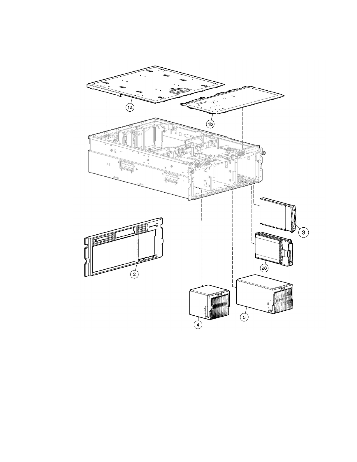
Mechanical Components Exploded View
Figure 1-1: Mechanical components exploded view
1-2 HP ProLiant DL580 Generation 2 Server Maintenance and Service Guide
Page 13

Mechanical Components Spare Parts List
Table 1-1: Mechanical Components Spare Parts List
Item Description Spare Part Number
Illustrated Parts Catalog
1 Access panels
a) Rear
b) Front
2 Front bezel 243669-001
3 SCSI hard drive blank 122759-001
4 Power supply blank 267133-001
5 Power supply, 800 W, hot-plug 192201-001
6 Cable management arm* 295792-001
7 Power cord retainer kit* 313825-001
* Not shown.
240241-001
HP ProLiant DL580 Generation 2 Server Maintenance and Service Guide 1-3
Page 14
Illustrated Parts Catalog
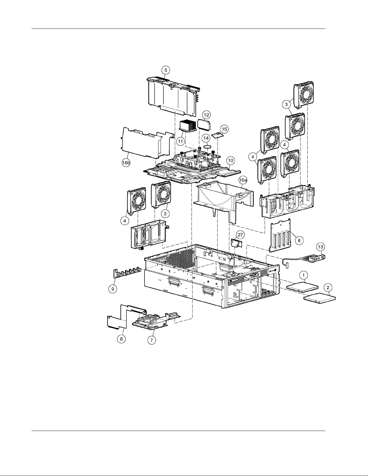
System Components Exploded View
Figure 1-2: System components exploded view
1-4 HP ProLiant DL580 Generation 2 Server Maintenance and Service Guide
Page 15

System Components Spare Parts List
Table 1-2: System Components Spare Parts List
Item Description Spare Part Number
Illustrated Parts Catalog
Media Storage Devices
1 Diskette drive, 12.7 mm, multibay 267132-001
2 CD-ROM drive, 24X, multibay 228508-001
Fans
3 Fan assembly, hot-plug, 120 × 38 mm 240243-001
4 Fan assembly, hot-plug, 120 × 25 mm 240244-001
Boards
5 Memory board 231126-001
6 SCSI backplane 231128-001
7 Diagnostic display board and lightpipe 249105-001
8 Pass-through board 249106-001
9 PCI-X Hot Plug board 231127-001
9a NIC, 10/100/1000 controller* 284848-001
9b NIC, Dual PCI-X NC7170* 313586-001
10 System board 231125-001
11 Processors
a) Processor, Xeon MP, 1.4-GHz/512 KB L3
b) Processor, Xeon MP, 1.6-GHz/1 MB L3*
c) Processor, Xeon MP, 1.5 GHz/1 MB L3*
d) Processor, Xeon MP, 1.9 GHz/1 MB L3*
e) Processor, Xeon MP, 2.0 GHz/2 MB L3*
f) Processor, Xeon MP, 2.0 GHz/1-MB L3*
g) Processor, Xeon MP, 2.5 GHz/1-MB L3*
h) Processor, Xeon MP, 2.8 GHz/2-MB L3*
i) Processor, Xeon MP, 2.2 GHz/2-MB L3*
j) Processor, Xeon MP, 2.7 GHz/2-MB L3*
k.) Processor, Xeon MP, 3.0 GHz/4-MB L3*
IMPORTANT: Mixing processor speeds and cache
sizes is not supported.
12 Processor power module (PPM) 266655-001
13 Power switch assembly 243670-001
272935-001
272936-001
309617-001
311277-001
309618-001
327839-001
327840-001
327841-001
352311-001
352312-001
352313-001
* Not shown
continued
HP ProLiant DL580 Generation 2 Server Maintenance and Service Guide 1-5
Page 16

Illustrated Parts Catalog
Table 1-2: System Components Spare Parts List continued
Item Description Spare Part Number
14 Battery, system, 3 V 153099-001
15 5i Plus memory module 260741-001
16 Plastics kit*
17 AC power cord, 15 A, 125 V* 237457-001
18 AC power cord, 10A, C14-C19* 311582-001
19 AC power cord, 16A, C19-C20* 295508-001
20 AC power cord, 20 A, 250 V* 237458-001
21 Rack-mounting hardware kit (company rack)* 313215-001
22 Rack-mounting hardware kit (third-party)* 291895-001
23 Cable kit, AC Power* 243671-001
24 Torx screwdriver, T-15* 199630-001
25 Country kit* 231091-001
26 Return kit* 279645-001
26a Hardware mounting kit, 4U* 286221-001
26b Cable Kit, Signal* 243670-001
27 Battery-Backed Write Cache Module, 4.8 V 260740-001
28 18.2-GB SCSI hard drive, hot-plug 10 K RPM 152190-001
28a 18.2-GB SCSI hard drive, universal, hot-plug, 15 K
28b 18.2-GB SCSI hard drive, U320, hot-plug, 15K 289240-001
28c 36.4-GB SCSI hard drive, hot-plug, 10 K RPM* 177986-001
28d 36.4-GB WUS, 1-inch hot-plug,15 K RPM* 233350-001
28e 36.4-GB SCSI Hard drive, U320, hot-plug, 10K 289041-001
28f 36.4-GB SCSI Hard drive, U320, hot-plug, 15K 289241-001
28g 72.8-GB WUS, 1-inch hot-plug, 10 K RPM* 233345-001
28h 72.8-GB SCSI hard drive, U320, hot-plug, 10K 289042-001
28i 72.8-GB SCSI hard drive, U320, hot-plug, 15K 289243-001
28j 146.8-GB SCSI hard drive, U320, hot-plug, 10K 289044-001
31 8X DVD-ROM drive* 268795-001
a) Processor air baffle
b) PCI Expansion board basket
Options
RPM*
243672-001
189395-001
continued
1-6 HP ProLiant DL580 Generation 2 Server Maintenance and Service Guide
Page 17

Illustrated Parts Catalog
Table 1-2: System Components Spare Parts List continued
Item Description Spare Part Number
Memory
32 256-MB DIMM (DDR SDRAM) 249674-001
33 512-MB DIMM (DDR SDRAM) 249675-001
34 1-GB DIMM (DDR SDRAM) 249676-001
35 2-GB DIMM (DDR SDRAM) 265791-001
* Not shown
HP ProLiant DL580 Generation 2 Server Maintenance and Service Guide 1-7
Page 18

Removal and Replacement Procedures
This chapter provides subassembly/module-level removal and replacement procedures for
ProLiant DL580 Generation 2 servers. After completing all necessary removal and
replacement procedures, run the Diagnostics Utility to be sure that all components operate
properly.
You need the following items for some procedures:
Torx T-15 tool
•
Flathead screwdriver
•
Diagnostics Utility on the HP SmartStart CD
•
Safety Considerations
Before performing service procedures, review the following safety information.
2
Electrostatic Discharge
A discharge of static electricity can damage static-sensitive devices or micro-circuitry. Proper
packaging and grounding techniques are necessary precautions to prevent damage. To
prevent electrostatic damage:
•
Transport products in static-safe containers such as conductive tubes, bags, or boxes.
•
Keep electrostatic-sensitive parts in their containers until they arrive at static-free
stations.
•
Cover workstations with approved static-dissipating material. Use a wrist strap connected
to the work surface and properly grounded (earthed) tools and equipment.
•
Keep work area free of nonconductive materials such as ordinary plastic assembly aids
and foam packing.
•
Be sure that you are properly grounded (earthed) when touching a static-sensitive
component or assembly.
•
Avoid touching pins, leads, or circuitry.
•
Use nonconductive field service tools.
HP ProLiant DL580 Generation 2 Server Maintenance and Service Guide 2-1
Page 19
Removal and Replacement Procedures
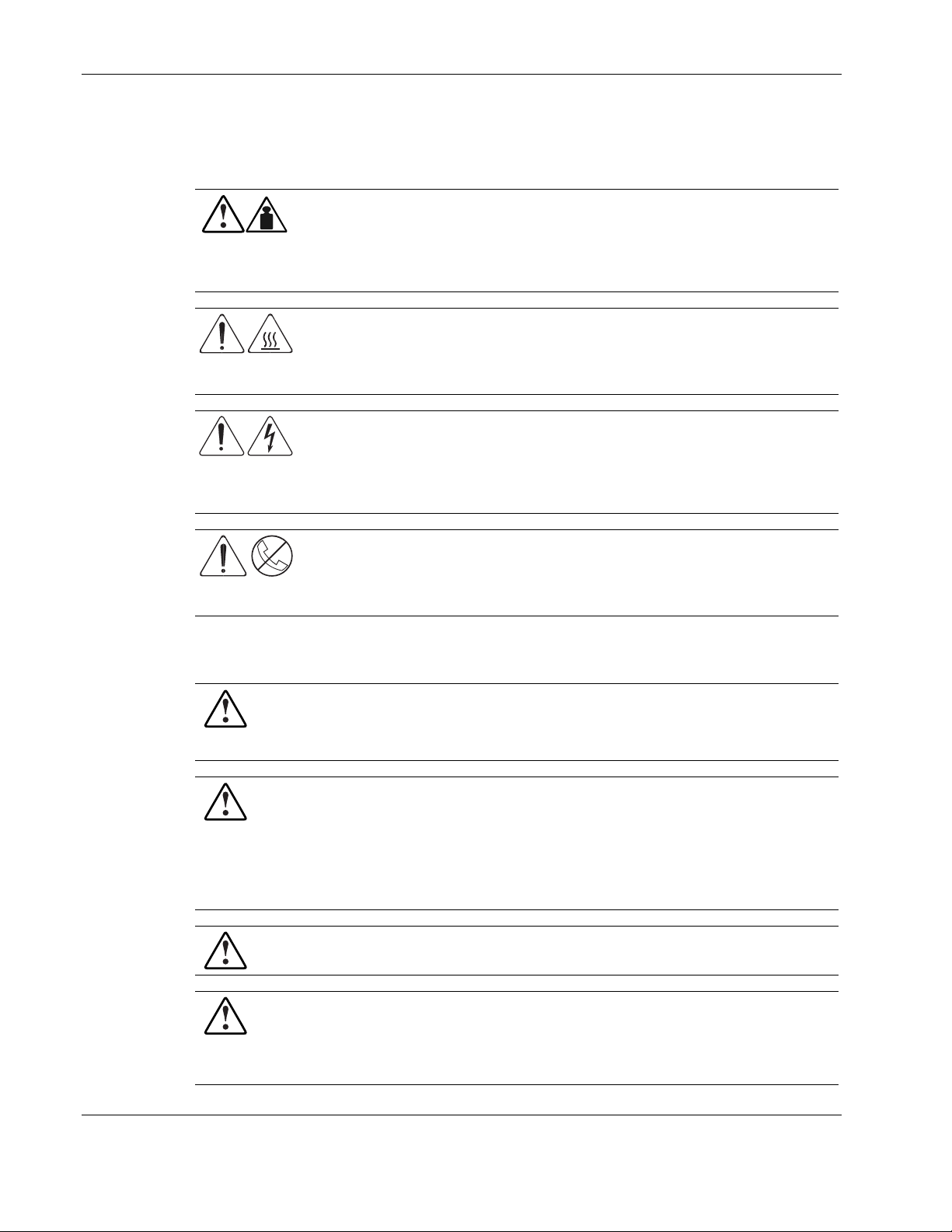
Symbols on Equipment
These symbols may be located on equipment in areas where hazardous conditions may exist.
Any product or assembly marked with these symbols indicates that the
component exceeds the recommended weight for one individual to handle safely.
WARNING: To reduce the risk of personal injury or damage to the equipment,
observe local occupational health and safety requirements and guidelines for
manual material handling.
Any surface or area of the equipment marked with these symbols indicates the
presence of a hot surface or a hot component.
WARNING: To reduce the risk of injury from a hot component, allow the surface
to cool before touching it.
Any surface or area of the equipment marked with these symbols indicates the
presence of electric shock hazards. The enclosed area contains no operator
serviceable parts.
WARNING: To reduce the risk of injury from electric shock hazards, do not open
this enclosure.
Any RJ-45 receptacle marked with these symbols indicates a network interface
connection.
WARNING: To reduce the risk of electric shock, fire, or damage to the equipment,
do not plug telephone or telecommunications connectors into this receptacle.
Rack Warnings and Cautions
WARNING: To reduce the risk of personal injury or damage to the equipment,
adequately stabilize the rack before extending a component outside the rack. Extend
only one component at a time. A rack may become unstable if more than one
component is extended.
WARNING: To reduce the risk of personal injury or damage to the equipment:
• Extend the leveling jacks to the floor.
• Rest the full weight of the rack on the leveling jacks.
• Attach the stabilizers to the rack if it is a single rack installation.
• Couple the racks together in multiple rack installations.
WARNING: When installing the server in a telco rack, adequately secure the rack frame
to the building structure at the top and bottom.
WARNING: To reduce the risk of personal injury or damage to the equipment, use two
or more people to safely unload the rack from the pallet. An empty 42U rack weighs
115 kg (253 lb), is over 2.1 m (7 ft) tall, and may become unstable when moved on its
casters. Handle the rack from both sides as it rolls down the ramp from the pallet. Do
not stand in front of the rack.
2-2 HP ProLiant DL580 Generation 2 Server Maintenance and Service Guide
Page 20
CAUTION: Always begin by mounting the heaviest item on the bottom of the rack. Continue
to populate the rack from the bottom to the top.
Server Warnings and Cautions
WARNING: Do not exceed the level of repair specified in the procedures in the product
documentation. All troubleshooting and repair procedures are detailed to allow only
subassembly or module-level repair. Because of the complexity of the individual
boards and subassemblies, do not attempt to make repairs at the component level or to
make modifications to any printed wiring board. Improper repairs can create a safety
hazard.
WARNING: To reduce the risk of personal injury from hot surfaces, allow the hot-plug
drives and the internal system components to cool before touching.
WARNING: To reduce the risk of electric shock or damage to the equipment:
• Do not disable the AC power cord grounding plug. The grounding plug is an
important safety feature.
• Plug the power cord into a grounded (earthed) electrical outlet that is easily
accessible at all times.
Removal and Replacement Procedures
• Unplug the power cord from each power supply to disconnect power to the
equipment.
WARNING: The installation of internal options and routine maintenance and service of
this product should be performed by individuals who are knowledgeable about the
procedures, precautions, and hazards associated with equipment containing
hazardous energy levels.
WARNING: Do not use conductive tools that could bridge live parts. Remove all
watches, rings, or loose jewelry when working in hot-plug areas of an energized server.
WARNING: Do not replace non-hot-plug components while power is applied to the
product. First, shut down the product and disconnect all AC power cords.
WARNING: Be sure that the AC power supply branch circuit that provides power to the
rack is not overloaded. Maintaining a low electrical current draw reduces the risk of
personal injury, fire, or damage to the equipment. The total rack load should not
exceed 80 percent of the branch circuit rating. Consult the electrical authority having
jurisdiction over your facility for wiring and installation requirements.
CAUTION: Protect the server from power fluctuations and temporary interruptions with a
regulating uninterruptible power supply (UPS). This device protects the hardware from
damage caused by power surges and voltage spikes and keeps the system in operation
during a power failure.
CAUTION: Do not operate the server for extended periods without the access panel.
Operating the server without the access panel results in improper airflow and improper cooling
that can lead to thermal damage.
HP ProLiant DL580 Generation 2 Server Maintenance and Service Guide 2-3
Page 21
Removal and Replacement Procedures
CAUTION: Reinstall each hard drive into the specific slot from which it was removed. Mixing
the hard drives adversely affects the system drive configuration.
Preparation Procedures
To access some components and perform certain service procedures, you must do one or
more of the following:
•
Extend the server from the rack.
If you are performing service procedures in an HP, Compaq branded, or third-party rack
cabinet, you can use the locking feature of the rack rails to support the server and gain
access to internal components.
•
Access internal components.
If you need to access internal components for removal or replacement, you can remove
the front and rear access panels without removing the server from the rack.
•
Power down the server.
If you must perform a non-hot-plug replacement procedure, power down the server.
•
Remove the server from the rack.
If the rack environment, cabling configuration, or the server location in the rack creates
awkward conditions, remove the server from the rack. If the server is installed in a telco
rack, you must remove the server from the rack to access internal components.
WARNING: Before lifting the server, remove all hot-plug power supplies and hard
drives to reduce the weight.
2-4 HP ProLiant DL580 Generation 2 Server Maintenance and Service Guide
Page 22
Locating and Removing the Torx T-15 Tool
Many hardware procedures in the ProLiant DL580 Generation 2 server are toolless, but a few
require the removal of Torx T-15 screws that have been installed for shipping or security
reasons. A Torx T-15 tool ships with the server for the removal of these screws.
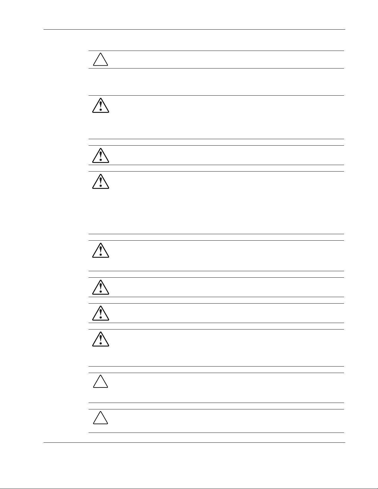
To locate and remove the Torx T-15 tool:
1. Locate the Torx T-15 tool on the back of the server. It is next to PCI-X slot 6.
2. Slide the tool out of the retaining clips.
Removal and Replacement Procedures
Figure 2-1: Locating and removing the Torx T-15 tool
HP ProLiant DL580 Generation 2 Server Maintenance and Service Guide 2-5
Page 23
Removal and Replacement Procedures
Extending the Server from the Rack
To perform service procedures, you must extend the server from the rack.
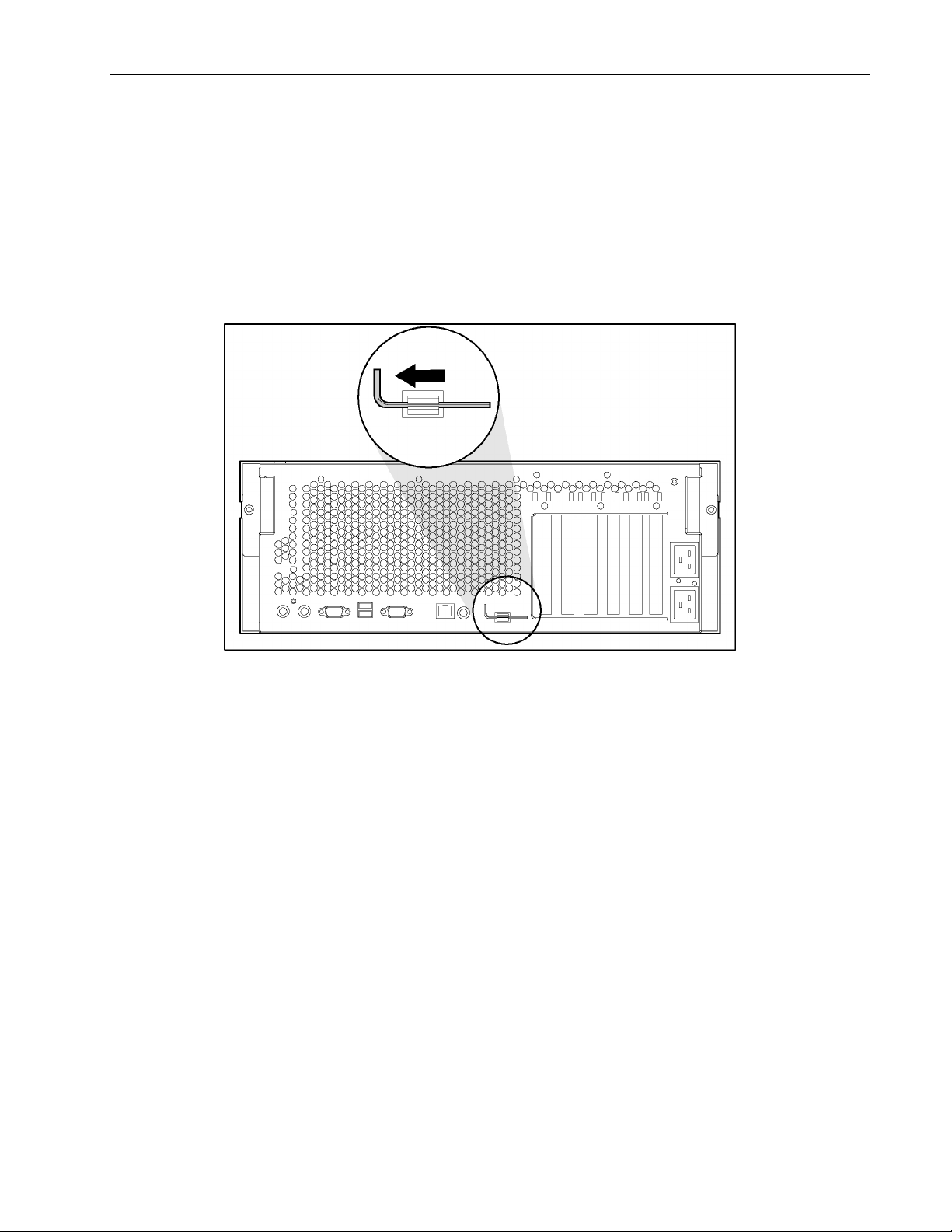
To extend the server from the rack:
1. Loosen the thumbscrews that secure the server to the front of the rack.
Figure 2-2: Loosening the front panel thumbscrews
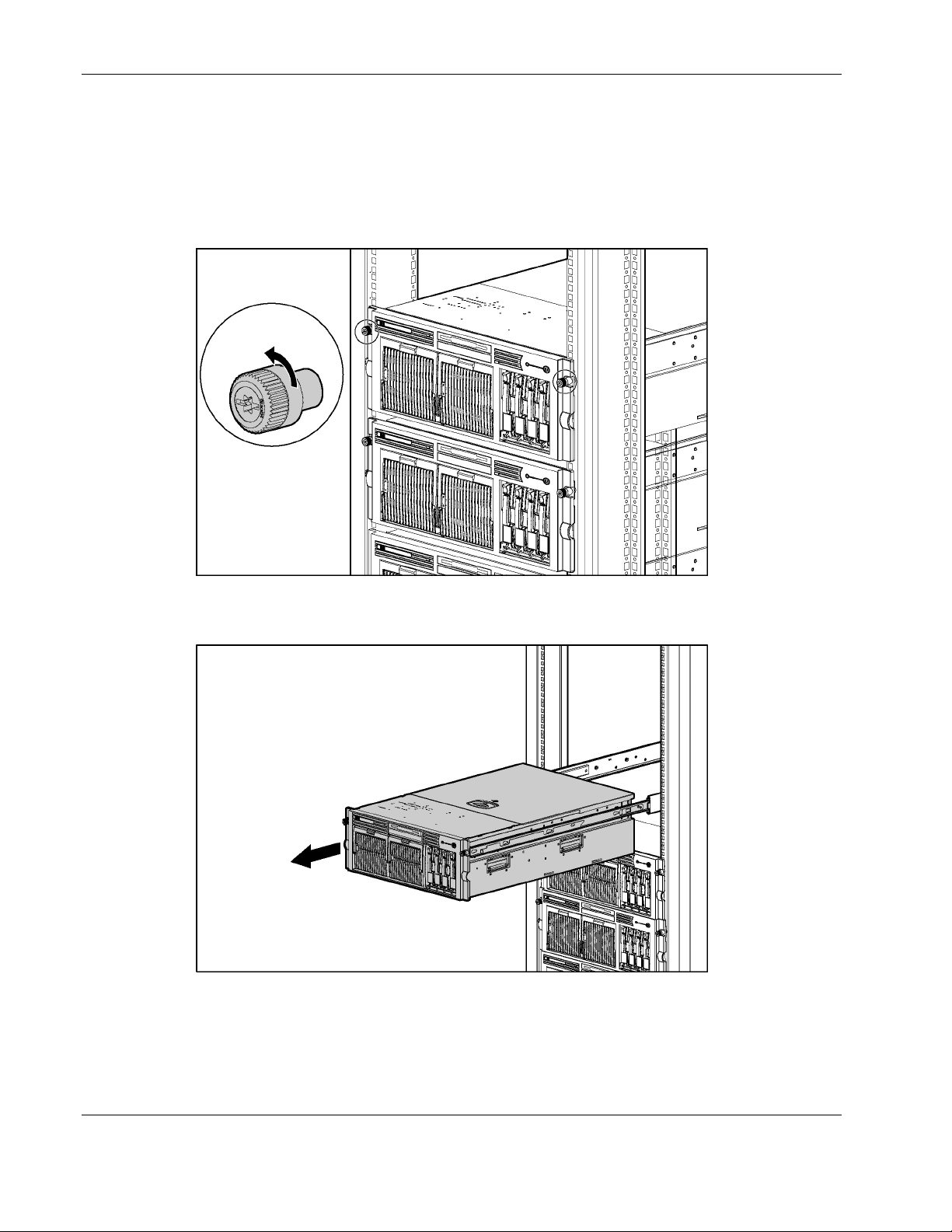
2. Extend the server on the rack rails until the server rail-release latches engage.
Figure 2-3: Extending the server from the rack
2-6 HP ProLiant DL580 Generation 2 Server Maintenance and Service Guide
Page 24
Removal and Replacement Procedures
WARNING: Be careful when pressing the rail-release levers and sliding the component
into or out of the rack. The sliding rails could pinch your fingertips.
3. To return the server to the rack, reach around the front of the server to press the
rail-release levers at the front of both server rails and continue to slide the server into the
rack.
Figure 2-4: Returning the server back into the rack
HP ProLiant DL580 Generation 2 Server Maintenance and Service Guide 2-7
Page 25
Removal and Replacement Procedures
Opening and Removing the Rear Access Panel
The ProLiant DL580 Generation 2 server has front and rear access panels that may need to be
opened and removed to access the system board, processors, memory slots, expansion slots,
and other internal components. Observe the following warnings and cautions when removing
the access panels.
WARNING: Before removing the access panels for non-hot-plug hardware options, be
sure that the power cords are disconnected from the electrical outlet.
WARNING: Pressing the Power On/Standby button sets the server to the standby
position, which removes power from most areas of the server. However, portions of the
power supply and some internal circuitry remain active until the AC power cord is
removed.
WARNING: To reduce the risk of personal injury from hot surfaces, allow the internal
system components to cool before touching.
CAUTION: Electrostatic discharge can damage electronic components. Properly ground
yourself before beginning any installation procedure.
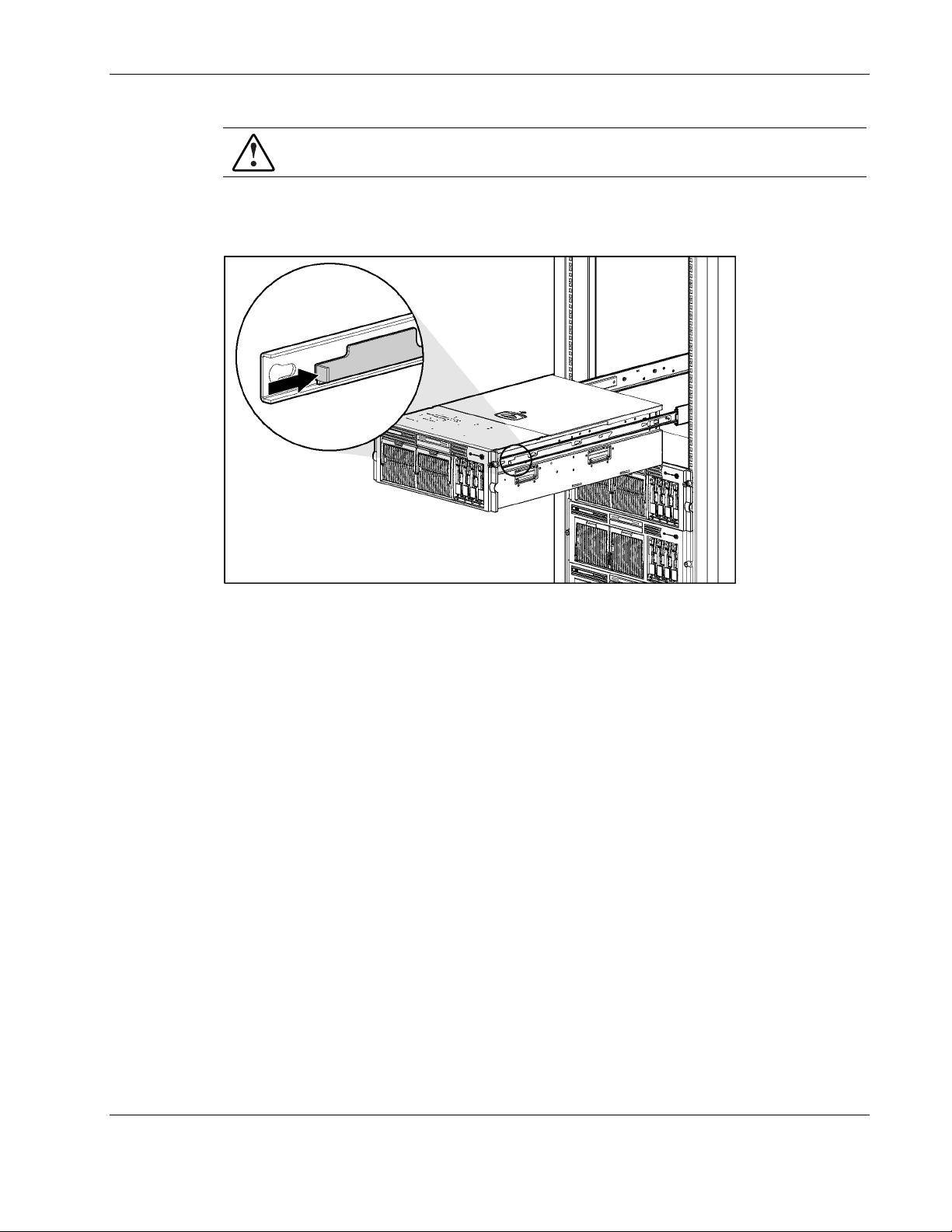
To open the rear access panel:
1. Extend or remove the server from the rack. Refer to “Extending the Server from the
Rack” in this chapter.
2. Disengage the lock on the rear panel using the Torx T-15 tool (1).
3. Using the handle on the rear access panel, slide the rear access panel toward the rear of
the unit (2). The springs raise the rear access panel.
Figure 2-5: Unlocking and sliding the rear access panel open
2-8 HP ProLiant DL580 Generation 2 Server Maintenance and Service Guide
Page 26
Removal and Replacement Procedures
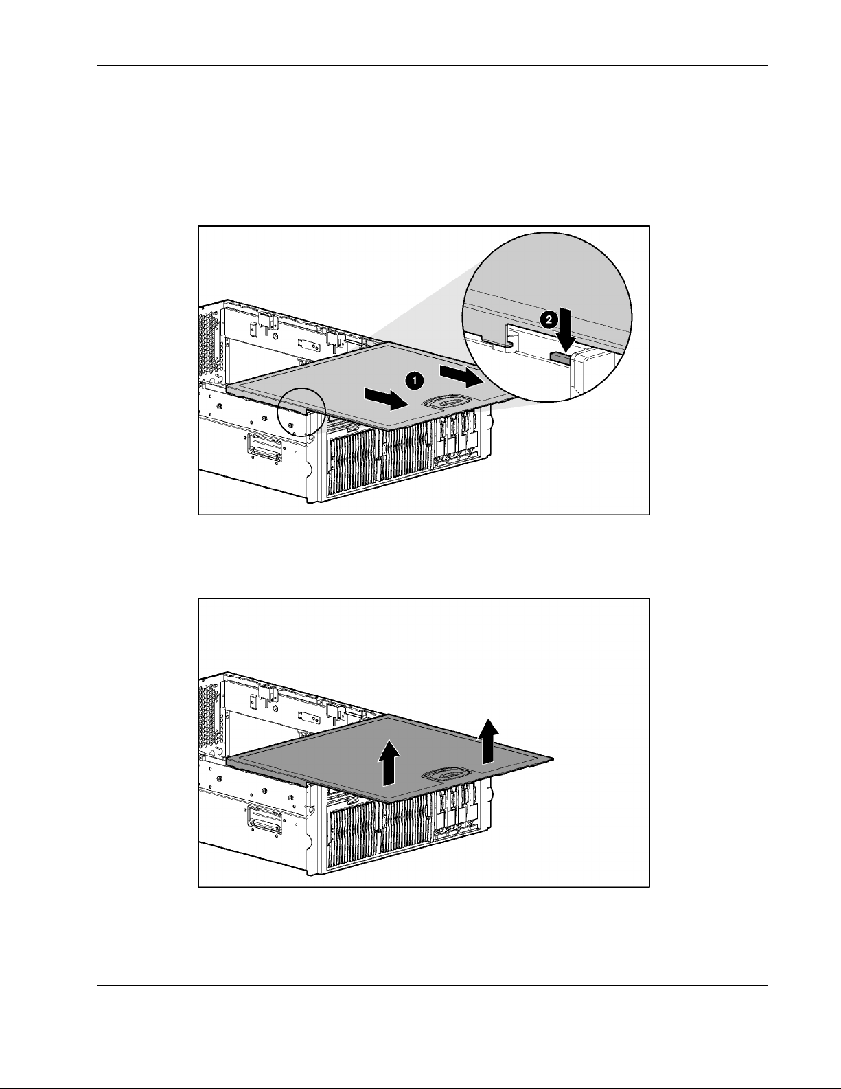
4. Slide the rear access panel toward the front of the server (1).
5. Push and hold the access panel release lever down (2) while sliding the rear access panel
forward about 2.54 cm (1 in).
IMPORTANT: The guide marks on the rear access panel and the server must line up before
proceeding to the next step.
Figure 2-6: Opening the rear access panel
6. Align the guide marks on the rear access panel and the chassis, and lift the rear access
panel from the server.
Figure 2-7: Removing the rear access panel
HP ProLiant DL580 Generation 2 Server Maintenance and Service Guide 2-9
Page 27
Removal and Replacement Procedures
Removing the Front Access Panel
To remove the front access panel:
1. Extend or remove the server from the rack. Refer to “Extending the Server from the
Rack” in this chapter.
2. Remove the rear access panel. Refer to “Opening and Removing the Rear Access Panel”
in this chapter.
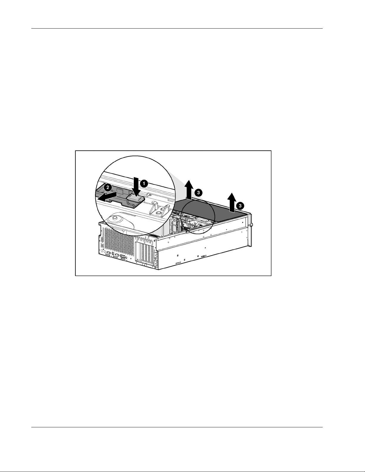
3. Remove the front access panel:
a. Press the release button located on the inside rear of the front access panel (1).
b. Slide the front access panel toward the rear of the server (2).
c. Remove the access panel (3).
Figure 2-8: Removing the front access panel
2-10 HP ProLiant DL580 Generation 2 Server Maintenance and Service Guide
Page 28

Replacing the Access Panels
To replace the access panels:
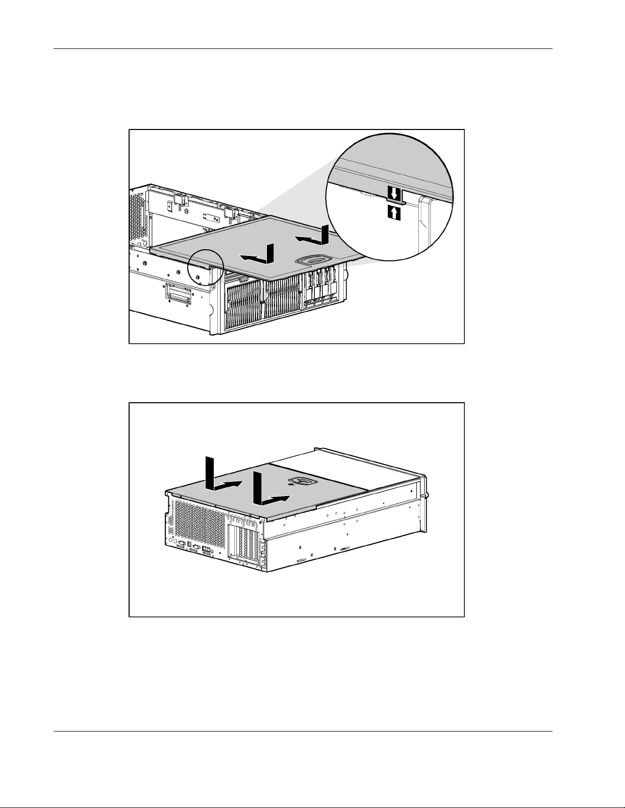
1. Place the front access panel on top of the server, and line up the guide marks on the front
access panel with the corresponding server guide marks.
2. With even pressure, push the front access panel down and slide it toward the front of the
server into the fitted slots.
Removal and Replacement Procedures
Figure 2-9: Replacing the front access panel
HP ProLiant DL580 Generation 2 Server Maintenance and Service Guide 2-11
Page 29
Removal and Replacement Procedures
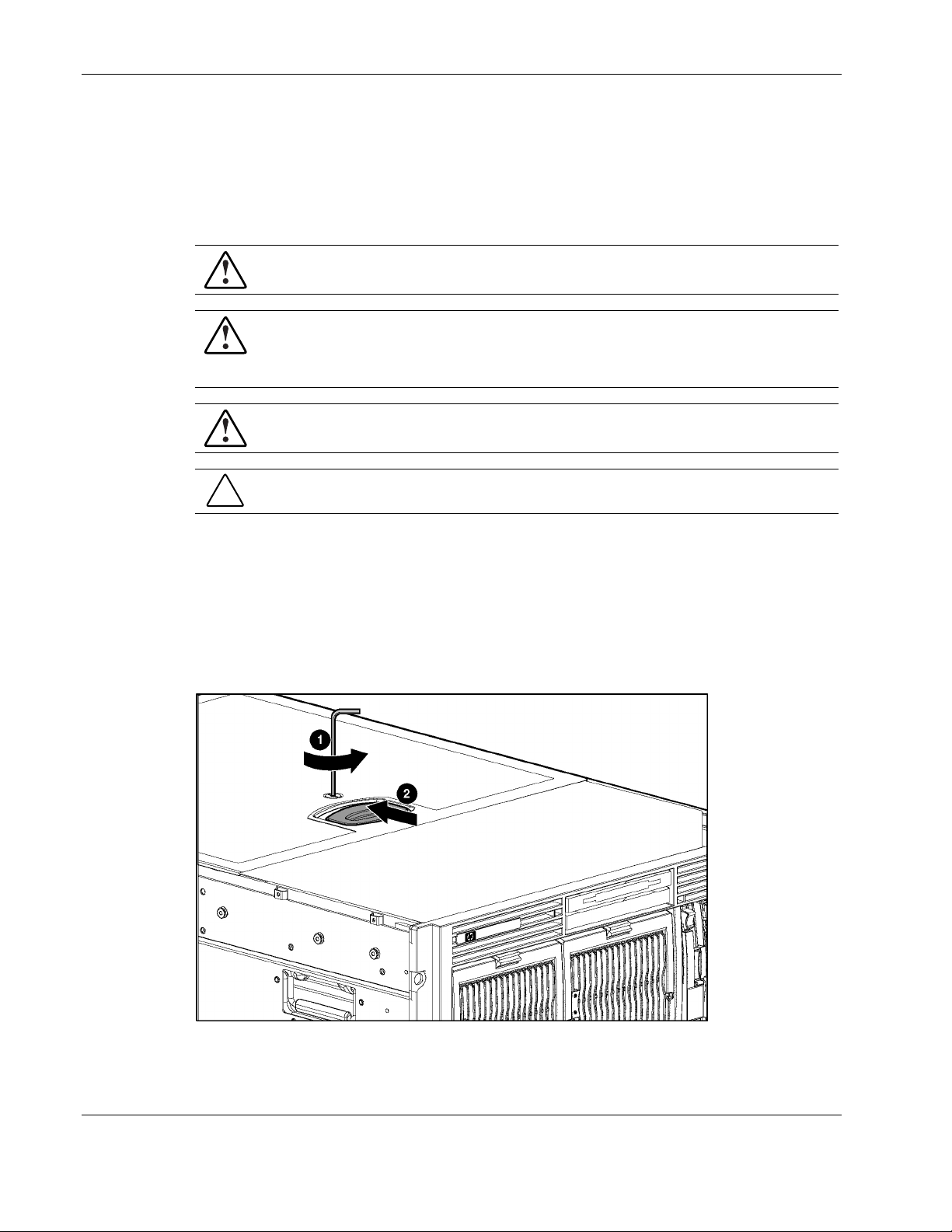
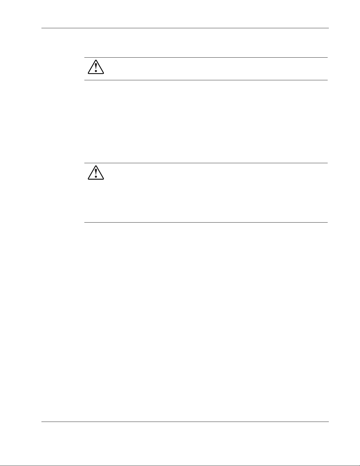
3. Place the rear access panel on top of the server and line up the guide marks on the rear
access panel with the corresponding server guide marks.
4. Slide the rear access panel toward the back of the server until it stops.
Figure 2-10: Lining up the guide marks
5. With even pressure, push the rear access panel down and slide it toward the front of the
server until it seats.
Figure 2-11: Installing the rear access panel
6. Use the Torx T-15 tool to turn the locking screw clockwise to lock the latch.
2-12 HP ProLiant DL580 Generation 2 Server Maintenance and Service Guide
Page 30
Powering Down the Server
WARNING: It is necessary to be knowledgeable of electrostatic discharge information
before preparing the server. For electrostatic discharge information, refer to
“Electrostatic Discharge ” in this chapter.
For all non-hot-plug procedures, you must power down the server. To power down the server:
1. Press the Power On/Standby button.
2. Be sure that the front panel power LED indicator is amber and that the fans are off.
3. Disconnect all AC power cords from the server.
4. Disconnect all external peripheral devices from the server.
Removing the Server from the Rack
WARNING: The server is very heavy, up to 44.5 kg (98 lb). To reduce the risk of
personal injury or damage to the equipment:
• Remove all hot-plug power supplies to reduce the weight of the server before
lifting it.
• Observe local occupational health and safety requirements and guidelines for
material handling.
• Get help to lift and maneuver the server.
Removal and Replacement Procedures
To remove the server from the rack:
1. Power down the server. Refer to “Power ing Down the Server” in this chapter.
2. Loosen the front panel thumbscrews that secure the server faceplate to the front of the
rack.
3. Extend the server from the rack. Refer to “Extending the Server from the Rack” i n this
chapter.
4. Remove the cables from the cable management arm and unplug the cables from the rear
of the server.
HP ProLiant DL580 Generation 2 Server Maintenance and Service Guide 2-13
Page 31

Removal and Replacement Procedures
5. Press the rail release levers on the rails and slide the server off the rack rails.
Figure 2-12: Removing the server from the rack
6. Place the server on a sturdy, level surface.
Reverse steps 1 through 4 to install the server into the rack.
2-14 HP ProLiant DL580 Generation 2 Server Maintenance and Service Guide
Page 32

Memory
Removal and Replacement Procedures
This section provides the following information about the memory components and
procedures in the ProLiant DL580 Generation 2 server:
Memory replacement guidelines
•
Memory board slot locations
•
Parts of the memory board
•
Memory board LEDs and icons
•
DIMM installation requirements
•
Removing a memory board
•
Removing a DIMM
•
Installing a DIMM
•
Installing a memory board
•
Configuring the memory
•
Memory Replacement Guidelines
DIMM and memory board installation, removal, and replacement procedures can be either
hot-plug or non-hot-plug procedures, depending on how the server is configured.
•
You cannot perform hot-plug procedures when the system is configured for:
— Advanced ECC memory
— Online spare memory
— Single-board mirrored memory
•
You can only perform a hot-plug replacement procedure:
— When the server is configured for hot-plug mirrored memory, enabling you to replace
failed or degraded DIMMs without powering down the server
— When the server is configured for Hot-Add functionality, enabling you to upgrade the
amount of memory without powering down the server
For more information about requirements and procedures for using Hot-Add functionality,
refer to the HP ProLiant DL580 Generation 2 and HP ProLiant ML570 Generation 2 Server
Hot-Add Memory booklet on the Documentation CD or the Compaq Reference Library on
www.hp.com.
The replacement procedures in this section apply to both hot-plug and non-hot-plug memory
replacement, except as noted.
CAUTION: Be sure to power down the server when performing these procedures in a server
that is not configured for hot-plug mirrored memory or Hot-Add functionality.
HP ProLiant DL580 Generation 2 Server Maintenance and Service Guide 2-15
Page 33
Removal and Replacement Procedures
Observe the following warnings when performing a hot-plug replacement procedure.
WARNING: Always comply with all electrostatic and thermal guidelines to prevent
bodily injury and ensure a properly functioning system when performing hot-plug
operations. For detailed information, refer to “Abou t this Guide” i n this guide.
WARNING: The rear access panel provides access to hazardous energy circuits. To
avoid risk of injury or damage to the equipment from hazardous energy, be sure the
door remains locked during normal operation or install the server in a controlled
access location.
WARNING: To reduce the risk of personal injury from hazardous energy or damage to
the equipment when working on energized servers:
• Remove all watches, rings, and any other loose fitting jewelry.
• Avoid the use of conductive tools inside the server that could bridge live parts.
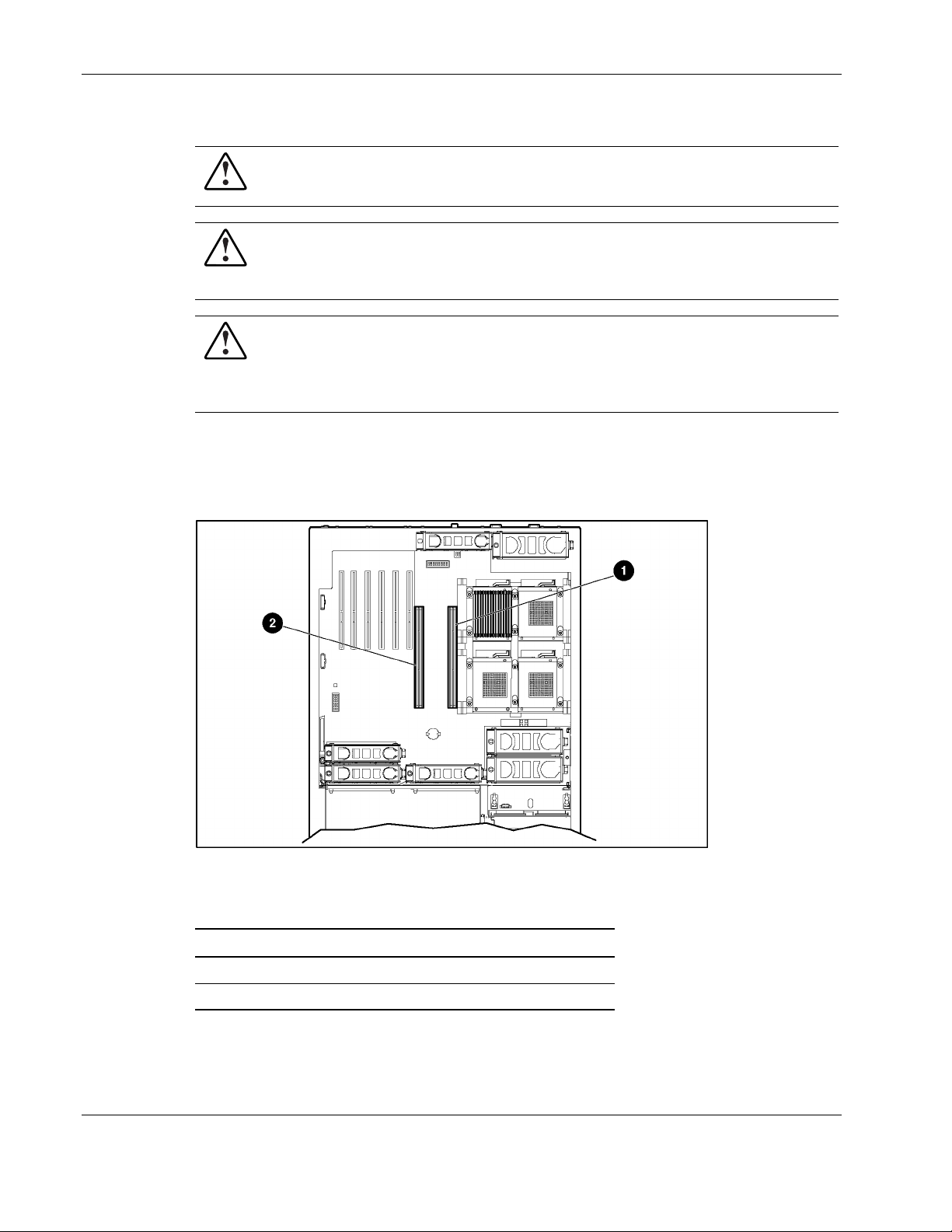
Memory Board Slot Locations
Use Figure 2-13 and Table 2-1 to identify the memory board slots on the system board.
Figure 2-13: Memory board slots
Table 2-1: Memory Board Slots
Item Description
1 Memory board slot 1
2 Memory board slot 2
2-16 HP ProLiant DL580 Generation 2 Server Maintenance and Service Guide
Page 34
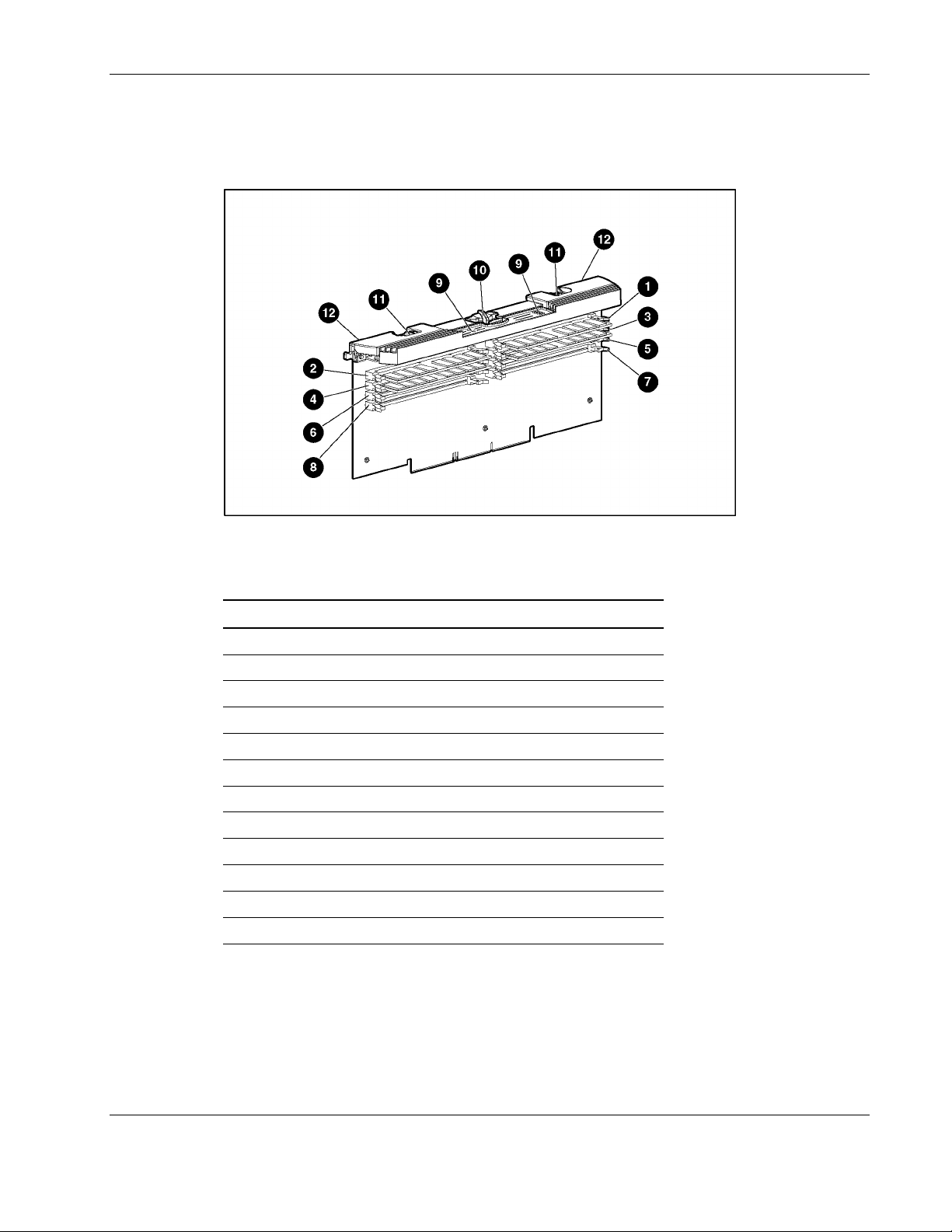
Parts of the Memory Board
Use Figure 2-14 and Table 2-2 to identify the parts of the memory board.
Figure 2-14: Parts of the memory board
Removal and Replacement Procedures
Table 2-2: Parts of the Memory Board
Item Description
1 DIMM slot 1, bank A (populated)
2 DIMM slot 2, bank A (populated)
3 DIMM slot 3, bank A (populated)
4 DIMM slot 4, bank A (populated)
5 DIMM slot 5, bank B
6 DIMM slot 6, bank B
7 DIMM slot 7, bank B
8 DIMM slot 8, bank B
9 LEDs
10 Locking switch
11 Release latches
12 Ejector levers
HP ProLiant DL580 Generation 2 Server Maintenance and Service Guide 2-17
Page 35
Removal and Replacement Procedures
Memory Board LEDs and Icons
Use Figure 2-15 and Table 2-3 through 2-7 to identify icons and LEDs and their status on the
memory board. Each table represents the LEDs for a specific memory mode. Be sure you are
referring to the correct table for the specific mode.
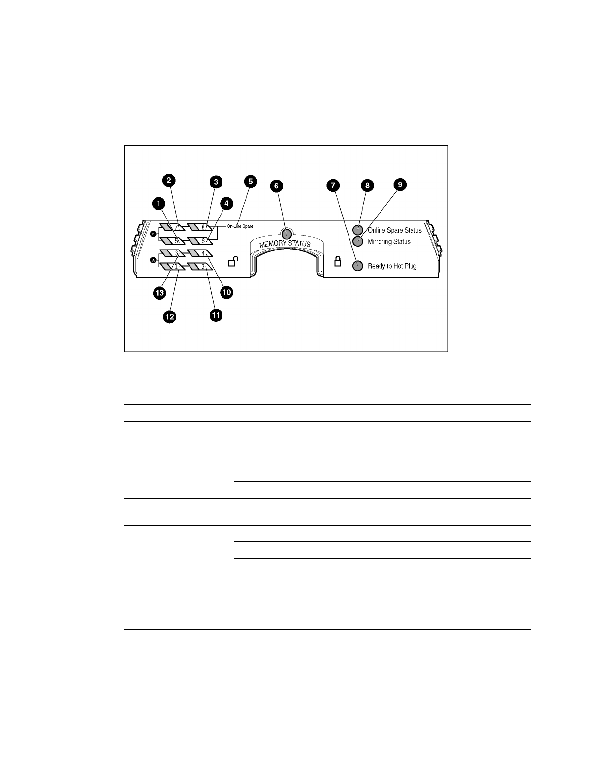
Figure 2-15: Memory board LEDs and icons
Table 2-3: Advanced ECC (Standard) Memory LEDs
Item Description Indicator Status
6 Memory
Status
7 Ready to
Hot Plug
1-4
and
10-13
DIMMs 1-8
status
All LEDs Flashing
Off Memory board is offline.
Green Memory board is online.
Flashing
green
Amber Memory error has occurred on this memory board.
Off Do not remove memory board. Advanced ECC
Off DIMM is not installed.
Green DIMM is installed.
Amber Memory error has occurred on this DIMM.
Flashing
amber
amber
Memory board is busy.
memory does not support hot-removal of boards.
Configuration error has occurred.
CAUTION: Memory board is in use; relock it
immediately.
2-18 HP ProLiant DL580 Generation 2 Server Maintenance and Service Guide
Page 36

Table 2-4: Online Spare Memory LEDs
Item Description Indicator Status
Removal and Replacement Procedures
6 Memory
Status
8 Online Spare
Status
7 Ready to
Hot Plug
5 Online Spare
text
1-4
and
10-13
All LEDs Flashing
DIMMs 1-8
status
Off Memory board is offline.
Green Memory board is online.
Flashing
green
Amber Memory error has occurred on this memory board.
Off Memory board is not configured for online spare
Green Online spare memory is functioning properly.
Amber Memory error has occurred and system has failed over
Off Do not remove memory board. Online spare memory
Off Bank is not configured as an online spare bank.
Green Bank is configured as an online spare bank.
Flashing
green
Off DIMM is not installed.
Green DIMM is installed.
Amber Memory error has occurred on this DIMM.
Flashing
amber
amber
Memory board is busy.
memory.
to the online spare bank.
does not support hot-plug capability.
Failure has occurred and online spare bank is active.
Configuration error has occurred.
CAUTION: Memory board is in use; relock it
immediately.
HP ProLiant DL580 Generation 2 Server Maintenance and Service Guide 2-19
Page 37

Removal and Replacement Procedures
Table 2-5: Single-Board Mirrored Memory LEDs
Item Description Indicator Status
6 Memory Status
Off Memory board is offline.
Green Memory board is online.
Flashing green Memory board is busy.
Amber Memory error has occurred on this memory
9 Mirroring Status
Off Memory board is not configured for mirrored
Green Single-board mirrored memory is functioning
Amber Memory error has occurred and system has
7 Ready to
Off Do not remove memory board. Single-board
Hot Plug
1-4 and
10-13
DIMMs 1-8
status
Off DIMM is not installed.
Green DIMM is installed.
Amber Memory error has occurred on this DIMM.
Flashing amber Configuration error has occurred.
All LEDs Flashing amber
board.
memory.
properly.
failed over to the mirrored bank(s).
mirrored memory does not support hot-plug
capability.
CAUTION: Memory board is in use; relock it
immediately.
2-20 HP ProLiant DL580 Generation 2 Server Maintenance and Service Guide
Page 38

Removal and Replacement Procedures
Table 2-6: Hot-Plug Mirrored Memory LEDs
Item Description Indicator Status
6 Memory Status
Off Memory board is offline.
Green Memory board is online.
Flashing green Memory board is busy.
Amber Memory error has occurred on this
memory board.
9 Mirroring Status
Off Memory board is not configured for
mirrored memory.
Green Hot-plug mirrored memory is functioning
properly.
Amber Memory error has occurred and system
has failed over to the mirrored board.
Off Do not remove memory board. 7 Ready to Hot Plug
Green Memory board can be hot-plugged.
1-4 and
10-3
DIMMs 1-8 status
Off DIMM is not installed.
Green DIMM is installed.
Amber Memory error has occurred on this
DIMM.
Flashing amber Configuration error has occurred.
All LEDs Flashing amber
CAUTION: Memory board is in use;
relock it immediately.
Table 2-7: Memory Board Icons
Description Status
Lock Memory board is locked and cannot be removed.
Unlock Memory board is unlocked, and is only hot-pluggable if the Ready to Hot Plug
LED is on.
Note: The icon at which the memory board switch is pointed indicates whether the memory board is
locked or unlocked.
HP ProLiant DL580 Generation 2 Server Maintenance and Service Guide 2-21
Page 39

Removal and Replacement Procedures
DIMM Installation Requirements
Observe the following DIMM configuration requirements when installing DIMM:
Use only industry-standard PC1600 registered DDR SDRAM DIMMs in 256-MB,
•
512-MB, 1-GB, and 2-GB capacities, and that support Error Checking and Correcting
(ECC).
Install DIMMs in groups of four, one bank at a time.
•
Groups of four DIMMs must be identical. Installing DIMMs of different capacities into
•
the same bank can degrade memory performance.
Bank A must always be populated. To ease subsequent DIMM installations, install the
•
DIMMs in sequential order.
IMPORTANT: HP recommends that you use only HP DIMMs. Third-party DIMMs may have additional
installation requirements. For information about third-party DIMM installation requirements, refer to the
Advanced Memory Protection white paper on the ProLiant website at www.hp.com.
IMPORTANT: You must power down the server before installing additional DIMMs. Follow all DIMM
configuration requirements carefully. If the DIMMs are not configured properly, you receive an error
message during POST.
Additional Requirements for Online Spare Memory Technology
In addition to the DIMM configuration requirements for advanced ECC memory, observe the
following DIMM configuration requirements when installing DIMMs for online spare
memory:
•
Memory board slot 1 must be populated.
•
Bank B on the memory board in slot 1 is always the online spare bank, even if two
memory boards are installed, and must be populated when the server is configured for
online spare memory.
•
DIMMs installed in the online spare bank must be of equal or greater capacity than each
of those in the remaining banks on both memory boards.
IMPORTANT: If memory board slot 1 Bank B is not populated, the system automatically switches to
advanced ECC memory and displays an error message during POST.
NOTE: When configured for online spare memory, the memory board has no hot-plug capabilities.
2-22 HP ProLiant DL580 Generation 2 Server Maintenance and Service Guide
Page 40
Removal and Replacement Procedures
Additional Requirements for Single-Board Mirrored Memory Technology
In addition to the DIMM configuration requirements for advanced ECC memory, observe the
following DIMM configuration requirements when installing DIMMs for single-board
mirrored memory:
Install only one board. The board must be installed in memory board slot 1.
•
Bank B of memory board 1 is the mirrored bank.
•
DIMMs in the mirrored bank must be configured identically to the bank they are
•
mirroring. Both banks must be populated with DIMMs of the same capacity.
IMPORTANT: If memory board slot 1 Bank B is not populated, the system automatically switches to
advanced ECC memory and displays an error message during POST.
NOTE: When configured for single-board mirrored memory, the system has no hot-plug capabilities.
Additional Requirements for Hot-Plug Mirrored Memory Technology
In addition to the DIMM configuration requirements for advanced ECC memory, observe the
following DIMM configuration requirements when installing DIMMs for hot-plug mirrored
memory:
Two memory boards must be installed.
•
Both memory boards must be configured identically. Corresponding banks (for instance,
•
bank A on the memory board in slot 1 and bank A on the memory board in slot 2) must
be populated with DIMMs of the same size and type.
Observe the following DIMM configuration requirements when performing a hot-plug
replacement:
Do not remove the memory board unless the Ready to Hot Plug LED is green.
•
If you replace a DIMM, the DIMM must be a PC1600 DDR SDRAM DIMM of the same
•
capacity as the DIMM you are replacing.
Removing a Memory Board
CAUTION: Electrostatic discharge can damage electronic components. Be sure you are
properly grounded before beginning any installation procedure.
To remove a memory board:
1. If the server is not configured for hot-plug mirrored memory, you must power down the
server. Refer to “Powering Down the Server” in this chapter.
Hot-plug replacement procedure: If the server is configured for hot-plug mirrored
memory, skip to step 2.
HP ProLiant DL580 Generation 2 Server Maintenance and Service Guide 2-23
Page 41
Removal and Replacement Procedures
2. Open the rear access panel. Refer to “Op ening and Removing the Rear Access Panel” in
this chapter.
Hot-plug replacement procedure: Determine which memory board contains the failed
DIMM by locating the memory board with an amber memory status LED and one or
more amber DIMM status LEDs. The Ready to Hot Plug LED must be green, indicating
that you can perform a hot-plug procedure.
NOTE: If the Ready to Hot Plug LED is off on both boards, you must power down the server
before replacing DIMMs.
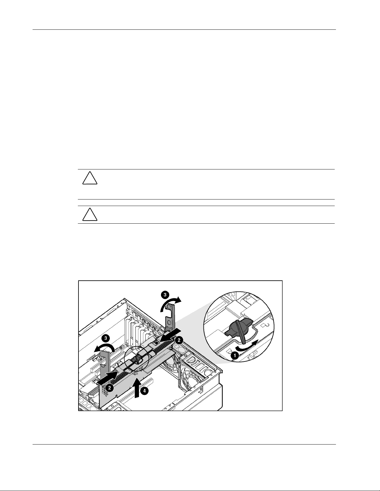
3. Disengage the locking switch (1).
Hot-plug replacement procedure: After turning the locking switch to the unlock
position, the LEDs turn off, except the amber LEDs. Wait until all green LEDs are off
before proceeding. Make note of which DIMM status LED remains illuminated amber,
indicating the DIMM you need to replace.
CAUTION: Do not attempt to unlock the memory board in an operational server when the
Ready to Hot Plug LED is not green. This will generate an audible alarm and cause the
memory board LEDs to flash amber. Proceeding to remove the memory board after the
audible and visible alarms causes system failure.
CAUTION: To prevent system failure, do not remove the memory board from the server until
the memory status LED stops blinking.
4. Press the release latches inward (2).
5. Pull the memory board up out of the server (3).
Hot-plug replacement procedure: While the memory board with the failed or degraded
DIMM is being replaced, the system continues to read and write from the operational
memory board.
Figure 2-16: Removing a memory board
2-24 HP ProLiant DL580 Generation 2 Server Maintenance and Service Guide
Page 42

Removing a DIMM
To remove a DIMM:
1. Remove the memory board. Refer to “Rem oving a Memory Board” in this chapter.
2. Place the memory board on a level, nonconductive surface.
3. Open the DIMM slot latches (1).
4. Remove the DIMM from the DIMM slot (2).
Removal and Replacement Procedures
Figure 2-17: Removing a DIMM
HP ProLiant DL580 Generation 2 Server Maintenance and Service Guide 2-25
Page 43

Removal and Replacement Procedures
Installing a DIMM
To install a DIMM:
1. Align the keyed portion of the bottom edge of the DIMM with the tab in the DIMM slot.
IMPORTANT: The bottom edge of the DIMM is keyed to fit into the DIMM slot only one way.
2. Press the DIMM firmly into the slot (1).
3. Push the latches into place (2).
Figure 2-18: Installing a DIMM
2-26 HP ProLiant DL580 Generation 2 Server Maintenance and Service Guide
Page 44

Installing a Memory Board
To install a memory board:
1. Align the memory board with the memory slot and memory board guide clips.
2. Slide the memory board into the server (1), and close the ejector levers to seat the
memory board firmly (2).
Hot-plug procedure: Any LEDs that were amber when the board was removed from the
server now illuminate amber again.
IMPORTANT: The LEDs relight amber during this step to enable you to verify again which DIMM
failed. If you have already replaced the failed DIMM, disregard the amber LEDs. The LEDs change
back to green after the locking switch is engaged, and the memory copy is complete.
3. Engage the locking switch (3).
Hot-plug procedure: All LEDs now turn off except the memory status LED, which
flashes green while data is copied from one memory board to the other. This process may
take up to a minute to complete. When the copying process is complete, the other LEDs
will re-illuminate as described in Table 2-11.
CAUTION: Do not remove the memory board while the memory status LED is flashing.
When the memory status LED is flashing, the memory board is transferring data.
Removing the memory board during data transfer may cause system failure.
Removal and Replacement Procedures
Figure 2-19: Installing a memory board
4. If the server is not currently configured for hot-plug mirrored memory, power up the
server. Refer to “ Powering Down the Server” in this chapter.
Hot-plug procedure: If the server is configured for hot-plug mirrored memory or Hot-
Add functionality, skip to step 7.
5. Configure the memory. Refer to “Conf iguring the Memory” in this chapter.
HP ProLiant DL580 Generation 2 Server Maintenance and Service Guide 2-27
Page 45

Removal and Replacement Procedures
6. Reference the LEDs on the top of the memory board to be sure that the memory is
functioning properly. The following table describes the LEDs for each memory
configuration when the DIMMs and memory board are installed and functioning
properly. For more information on LEDs, refer to Chapter 4 “Conn ectors, LEDs, and
Switches.”
Table 2-8: Memory LED States on a Properly Configured Memory Board
Memory Status Green Green Green Green
DIMMs 1-8, if
populated
Online Spare
Status
Mirroring Status Off Off Green Green
Online Spare
text*
Ready to Hot
Plug
*If two memory boards are installed, the online spare text is only illuminated for the memory board in
slot 1.
Memory Configuration LED
Advanced ECC
(Standard
Memory)
Green Green Green Green
Off Green Off Off
Off Green Off Off
Off Off Off Green
Online Spare
Memory
Single-Board
Mirrored
Memory
Hot-Plug
Mirrored
Memory
7. Close the rear access panel.
8. Reinstall the server in the rack.
Configuring the Memory
Configuring the servers memory system of the server requires configuring both hardware and
software. To configure the memory:
1. Choose one of the following memory configurations:
— Standard memory (Advanced ECC)
— Online spare memory
— Single board mirrored memory
— Hot-plug mirrored memory
For a discussion of how to determine the memory technology best suited for your
requirements, refer to the Advanced Memory Protection white paper on the ProLiant
website at
2. Remove the memory board. Refer to “Rem oving a Memory Board” in this chapter.
www.hp.com.
2-28 HP ProLiant DL580 Generation 2 Server Maintenance and Service Guide
Page 46

Removal and Replacement Procedures
3. Install the required DIMMs based on your desired memory configuration. Be sure to
follow all DIMM installation requirements. Refer to “DIMM Installation Requir ements”
in this chapter for the desired memory configuration.
4. Install the memory board. Refer to “Ins talling a Memory Board” in this chapter.
5. Configure the DIMMs:
a. Power on the server.
b. Press the F9 key to enter RBSU.
c. Select Advanced Options.
d. Change POST Speed Up to disable (to test the replaced memory).
e. Press any key to return to the RBSU main menu.
f. Select System Options.
g. Select Advanced Memory Protection.
h. Select the desired memory mode.
i. Press the Esc key twice to go back to the main RBSU menu.
j. Press the F10 key to exit RBSU. The server reboots and tests all memory in the
system.
k. Once the memory has been tested, re-enable POST Speed Up for faster system boot,
if desired.
IMPORTANT: To reconfigure the memory mode after initial setup, you must reboot the system
and enter RBSU.
HP ProLiant DL580 Generation 2 Server Maintenance and Service Guide 2-29
Page 47

Removal and Replacement Procedures
Hot-Plug Procedures
You can perform removal and replacement procedures for some server components without
powering down the server. This section describes the removal and replacement procedures for
the following hot-plug components:
Hard drive blanks
•
Hot-plug SCSI hard drives
•
Power supply blank
•
Hot-plug power supplies (must have two power supplies installed for it to be hot-plug
•
capable)
PCI and PCI-X Hot Plug expansion boards (in hot-plug slots)
•
Hot-plug fans
•
Hot-plug mirrored memory boards (refer to “Memory” in this chapt er)
•
Hard Drive Blanks
To remove a hard drive blank:
1. Push the sliding release button to unlock the blank (1).
2. Pull the drive blank out of the drive cage (2).
Figure 2-20: Removing a drive blank
NOTE: Keep the blank for future use.
Reverse steps 1 and 2 to replace a drive blank.
2-30 HP ProLiant DL580 Generation 2 Server Maintenance and Service Guide
Page 48

Hot-Plug SCSI Hard Drives
Drive Replacement Precautions
Be aware of the following guidelines cautioning unsafe hot-plug replacement.
•
Do not remove a degraded drive if any other member of the array is offline (the online
LED is off). No other drive in the array is hot-pluggable without data loss. The exception
to this is the use of RAID 1+0 as a fault-tolerant configuration. In this case, drives are
mirrored in pairs. More than one drive can fail and be replaced as long as the drive or
drives they are mirroring are online.
•
Do not remove a degraded drive if any member of an array is missing (removed
previously and not yet replaced).
•
Do not remove a degraded drive if any member of an array is being rebuilt, unless the
drive being rebuilt has been configured as an online spare. The online LED for the drive
flashes green or amber, indicating that a replaced drive is being rebuilt from the data
stored on the other drives.
NOTE: An online spare drive does not activate and start rebuilding after a predictive failure alert
because the degraded drive is still online. The online spare activates only after a drive in the array
has failed.
Removal and Replacement Procedures
•
Do not replace multiple degraded drives at the same time, since the fault tolerance can be
compromised. When a drive is replaced, the controller uses data from the other drives in
the array to reconstruct data on the replacement drive. If more than one drive is removed,
a complete data set is not available to reconstruct data on the replacement drive or drives,
and permanent data loss can occur.
CAUTION: Do not turn off any external unit when the server containing. A Smart Array
controller is powered up. Also, do not power up the server before powering up the drive
enclosure. If these ordering rules are not followed, the Smart Array controller may mark
the drives in this enclosure as failed, resulting in permanent data loss.
HP ProLiant DL580 Generation 2 Server Maintenance and Service Guide 2-31
Page 49
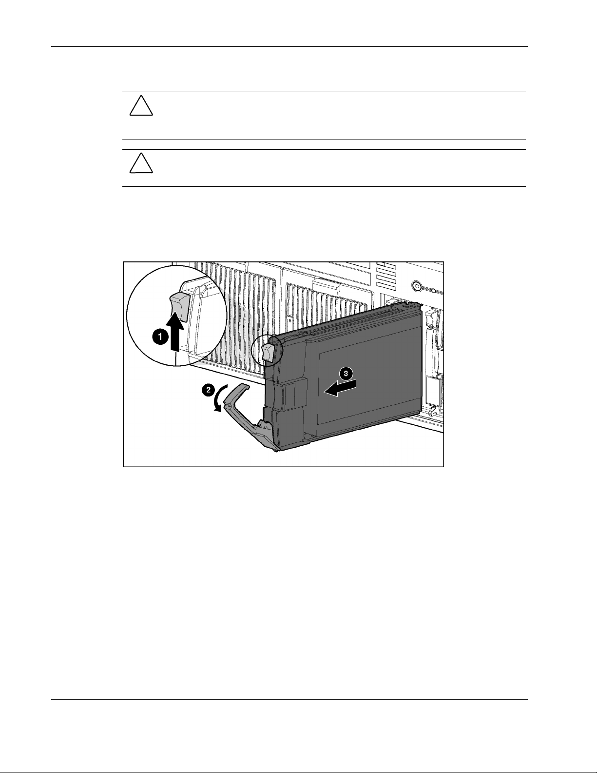
Removal and Replacement Procedures
To remove a non-functioning hot-plug SCSI hard drive:
CAUTION: Remove or replace a hard drive only when the drive failure LED is amber. Data
loss can occur if a drive is removed when the drive online LED is green. Refer to “Hot-Plug
SCSI Hard Drive LEDs” in Chapter 4, “Connectors, LEDs, and Switches,” for more
information.
CAUTION: Remove or replace only one hard drive at a time. The controller relies on other
drives to reconstruct data on the replaced drive. Drive reconstruction is active when the
drive online LED is flashing green.
1. Press the release button to unlock the ejector lever on the hard drive (1).
2. Open the ejector lever to release the drive (2).
3. Slide the drive out of the cage (3).
Figure 2-21: Removing a hot-plug SCSI hard drive
IMPORTANT: Always populate hard drive bays starting with the lowest SCSI ID.
Reverse steps 1 through 3 to replace a hot-plug SCSI hard drive.
2-32 HP ProLiant DL580 Generation 2 Server Maintenance and Service Guide
Page 50
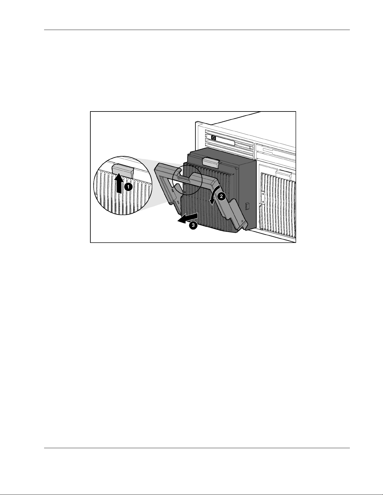
Power Supply Blank
To remove a power supply blank:
1. Press the lever-release button on the handle of the power supply blanks (1).
2. Pull on the lever to release the blank (2).
3. Remove the power supply blank from the server (3).
Removal and Replacement Procedures
Figure 2-22: Removing a power supply blank
NOTE: Keep the power supply blank for future use.
Reverse steps 1 through 3 to replace a power supply blank.
HP ProLiant DL580 Generation 2 Server Maintenance and Service Guide 2-33
Page 51
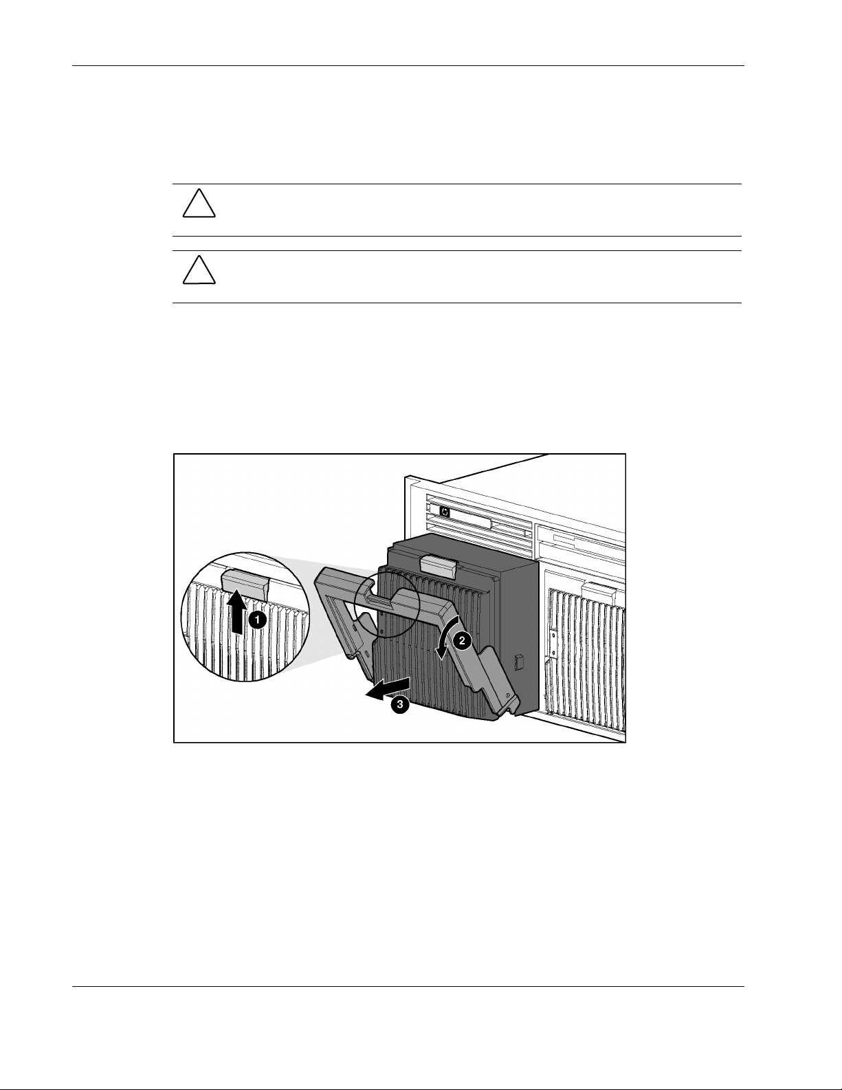
Removal and Replacement Procedures
Hot-Plug Power Supplies
For information on power supply diagnosis, refer to “Hot-Plug Po wer Supply LEDs” in
Chapter 4, ‘Connectors, LEDs, and Switches.”
CAUTION: Do not remove a hot-plug power supply unless there are two power supplies
installed. If second power supply is not installed, the system must be powered down to
remove the power supply.
CAUTION: Hot-plug power supplies for the ProLiant DL580 Generation 2 server are keyed to
be sure that only 800-W hot-plug power supplies can be installed in the server. The handles
on 800-W power supplies are black to distinguish them from other power supplies.
To remove a hot-plug power supply:
1. Remove any shipping screws from the bottom of the server, if installed.
2. Press the lever-release button on the handle of the power supply (1).
3. Pull on the lever to release the power supply (2).
4. Remove the power supply from the server (3).
Figure 2-23: Removing a hot-plug power supply
Reverse steps 1 through 4 to replace a hot-plug power supply.
2-34 HP ProLiant DL580 Generation 2 Server Maintenance and Service Guide
Page 52

PCI and PCI-X Hot Plug Expansion Boards
CAUTION: Do not attempt a PCI-X Hot Plug procedure if the operating system does not
provide PCI-X Hot Plug support or if you do not have the appropriate device drivers installed.
Failure to take these precautions causes system shutdown and risks data integrity.
CAUTION: To avoid critical errors, do not open the expansion slot latch if the green power
LED is on or blinking. Use the PCI-X Hot Plug button or the software application to turn off
power to the slot.
Use either the PCI-X Hot Plug button on the server or the PCI-X Hot Plug Utility of the
operation system to control the PCI-X Hot Plug slots.
• • The PCI-X Hot Plug button and the PCI-X Hot Plug Utility enable you to power up or
power down a PCI-X Hot Plug expansion slot. The PCI-X Hot Plug button enables direct
access at each hot-plug expansion slot.
PCI-X Hot Plug software support for each operating system is available online. For more
information, refer to the PCI Hot Plug Administrator’s Guide on the Documentation CD.
Removal and Replacement Procedures
HP ProLiant DL580 Generation 2 Server Maintenance and Service Guide 2-35
Page 53
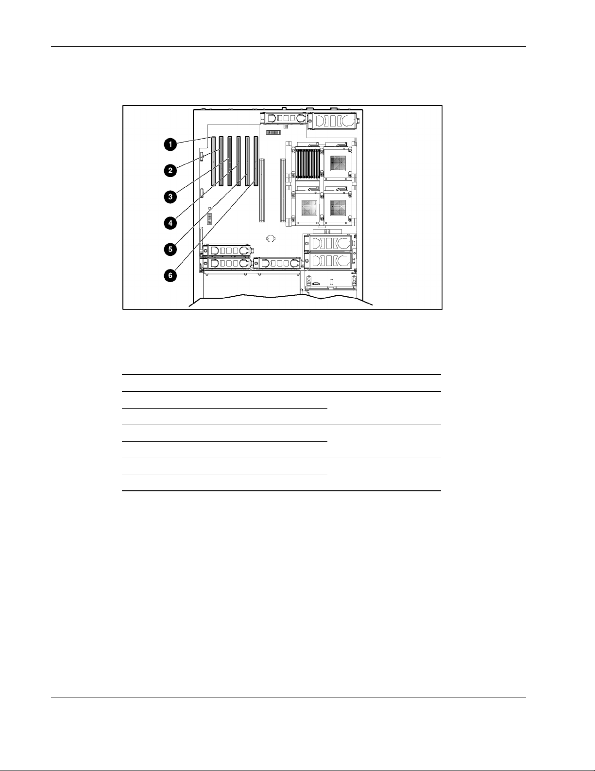
Removal and Replacement Procedures
The ProLiant DL580 Generation 2 server includes six PCI-X expansion slots. Use
Figure 2-24 and Table 2-9 to identify each slot.
Figure 2-24: PCI-X slot locations
Table 2-9: ProLiant DL580 Generation 2 PCI-X Expansion Slots and
Buses
Item Description Bus
1 Slot 1 (non-hot-plug)
2 Slot 2 (non-hot-plug)
3 Slot 3 (hot-plug)
4 Slot 4 (hot-plug)
5 Slot 5 (hot-plug)
6 Slot 6 (hot-plug)
Shared bus 10
Shared bus 6
Shared bus 2
To remove an expansion board from a PCI-X Hot Plug slot
1. Extend the server from the rack. Refer to “Extending the Server from the Rack” i n this
chapter.
2. Open the rear access panel. Refer to “Op ening and Removing the Rear Access Panel” in
this chapter.
2-36 HP ProLiant DL580 Generation 2 Server Maintenance and Service Guide
Page 54
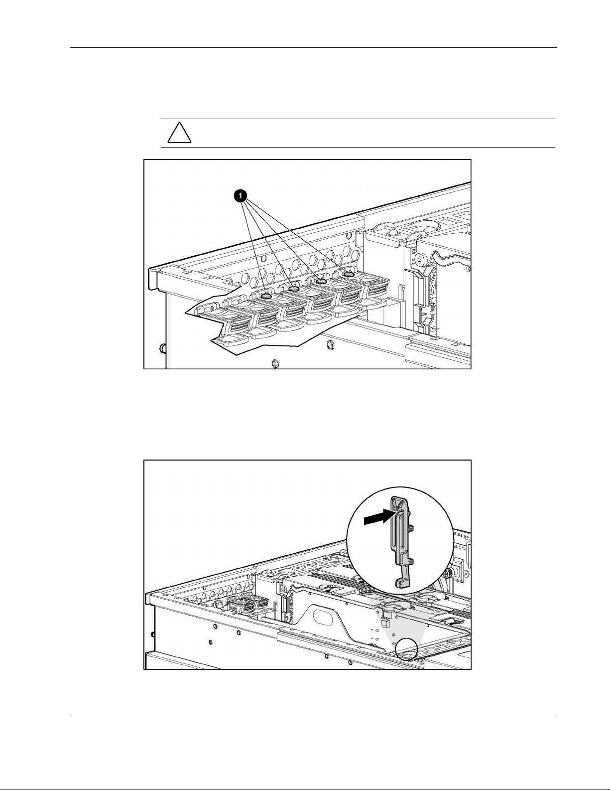
Removal and Replacement Procedures
3. Press the port-colored PCI-X Hot Plug button (1) to turn off power to the slot. The power
LED flashes until shutdown is complete. Refer to “PCI-X Hot Plug LEDs” in Chapter 4,
“Connectors, LEDs, and Switches,” to determin e the current PCI-X Hot Plug slot status.
CAUTION: To prevent data loss, do not open an expansion slot latch when the power
LED for the slot is on.
Figure 2-25: PCI-X Hot Plug button
4. When the power LED for the slot is off, disconnect any cables connected to the selected
expansion board.
5. Press the PCI-X retaining clip until it locks in the open position, releasing one side of the
board.
Figure 2-26: Pressing the PCI-X retaining clip
HP ProLiant DL580 Generation 2 Server Maintenance and Service Guide 2-37
Page 55

Removal and Replacement Procedures
6. Push the tab on the expansion slot latch (1).
7. Swing the latch back to unlock the expansion board (2).
8. Lift the expansion board release handle to disengage the board from the slot (3).
9. Remove the board from the slot (4).
Reverse steps 1 through 9 to replace the expansion board.
Figure 2-27: Removing a PCI-X Hot Plug expansion board
2-38 HP ProLiant DL580 Generation 2 Server Maintenance and Service Guide
Page 56
Performance Balancing
Before replacing the expansion board, review the following recommendations.
Balancing is the paired arrangement of expansion boards for optimal performance based on
the bus architecture of the expansion slots. Properly balancing the boards across buses can
improve performance. To balance expansion boards:
• • Populate slots from the center of the server to ensure optimal thermal conditions. Slot 6 is
in the center of the server and has the best cooling.
Populate slots across different buses before populating two slots on the same bus.
Table 2-10 provides a guideline for slot population order based on the previous
recommendations.
NOTE: HP recommends that the optional Remote Insight Lights-Out Edition II (RILOE II) board be
populated in slot 1 due to internal cabling requirements.
NOTE: The slot population order that follows is a recommendation only; any PCI or PCI-X expansion
board may reside in any slot.
Table 2-10: Recommended PCI-X Expansion Slot Population Order
Slot Number Population Order
6 1
5 4
4 2
3 5
2 3
1 6
Removal and Replacement Procedures
Shared PCI-X bus 2
Shared PCI-X bus 6
Shared PCI-X bus 10
The system BIOS detects the PCI-X devices in the slots in this order:
5-6-3-4-1-2
For more information about PCI-X bus architecture and numbering, refer to the white paper,
PCI Bus Numbering in a Windows NT Environment, on the product website at
HP ProLiant DL580 Generation 2 Server Maintenance and Service Guide 2-39
www.hp.com.
Page 57
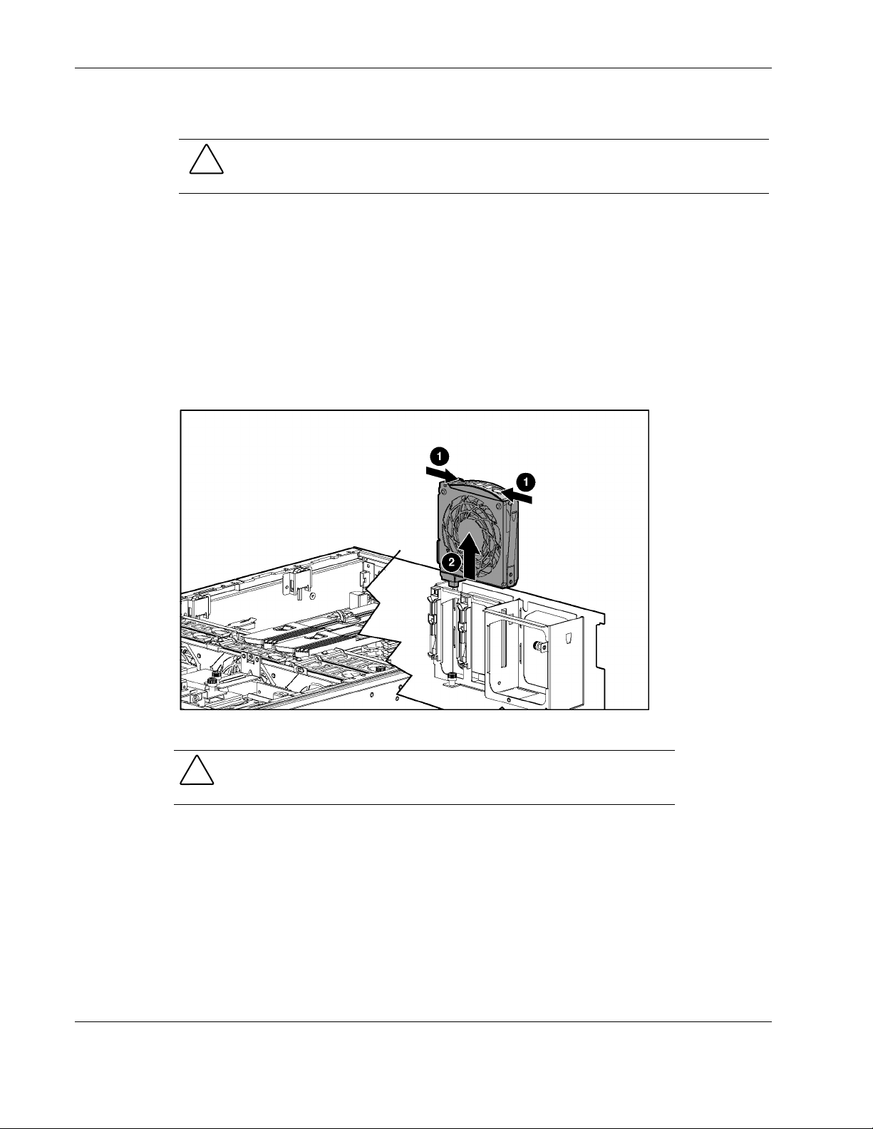
Removal and Replacement Procedures
Hot-Plug Fans
CAUTION: Do not attempt to remove and replace a fan as a hot-plug procedure unless the
fan zone is redundant. For more information, refer to the HP ProLiant DL580 Generation 2
Server Setup and Installation Guide.
To remove a hot-plug fan:
1. Extend the server from the rack. Refer to “Extending the Server from the Rack” i n this
chapter.
2. Open the rear access panel. Refer to “Op ening and Removing the Rear Access Panel” in
this chapter.
3. Identify the failed fan by locating the fan with the amber LED.
4. Pull the tabs on the top of the fan (1).
5. Remove the fan from the server (2).
Figure 2-28: Removing a hot-plug fan
CAUTION: Do not operate the server for extended periods without the access
panel installed. Operating the server without the access panel results in
improper airflow that can lead to thermal damage.
Reverse steps 1 through 5 to replace a hot-plug fan.
For information on hot-plug fan diagnosis, refer to “Hot-Plug Fan” in Chapter 4,
“Connectors, LEDs, and Switches.”
2-40 HP ProLiant DL580 Generation 2 Server Maintenance and Service Guide
Page 58

Non-Hot-Plug Procedures
In order to remove or replace any non-hot-plug component, you must first power down the
server. The slimline drive procedure is the only procedure that you can perform without
removing the rear access panel.
This section describes the removal and replacement procedures for the following
non-hot-plug components:
Slimline drives
•
Front bezel
•
Power button/LED assembly
•
Processor air baffle
•
Processor power modules
•
Processors
•
Non-hot-plug PCI-X expansion boards
•
PCI-X expansion board basket
•
Removal and Replacement Procedures
PCI-X Hot Plug Expansion board
•
SCSI cables
•
Front fan cage
•
Pass-through board
•
Removable media board
•
Rear fan cage
•
Battery-backed write cache assembly
•
SCSI backplane
•
System battery
•
System board
•
AC filter cable assembly
•
WARNING: To reduce the risk of personal injury or damage to the equipment, the
installation of options other than hot-plug power devices should be performed only by
individuals who are qualified to service computer equipment and trained to deal with
products capable of producing hazardous energy levels.
HP ProLiant DL580 Generation 2 Server Maintenance and Service Guide 2-41
Page 59

Removal and Replacement Procedures
Slimline Drives
To remove a drive from a slimline drive bay:
1. Power down the server. Refer to “Power ing Down the Server” in this chapter.
2. Push the release button with the Torx T-15 tool (1).
3. Pull the drive out of the slimline drive bay (2).
Figure 2-29: Removing a drive from a slimline drive bay
To replace a slimline drive, slide the drive into the slot until it engages the connector.
IMPORTANT: For the diskette drive to be bootable, it must be installed in the top slimline drive bay.
For the CD-ROM or DVD-ROM drive to be bootable, it must be installed in the bottom slimline drive
bay.
2-42 HP ProLiant DL580 Generation 2 Server Maintenance and Service Guide
Page 60

Front Bezel
Removal and Replacement Procedures
To remove the front bezel:
1. Power down the server. Refer to “Power ing Down the Server” in this chapter.
2. Extend the server from the rack. Refer to “Extending the Rack from the Server” in this
chapter.
3. Remove the rear access panel. Refer to “Opening and Removing the Rear Access Panel”
in this chapter.
4. Remove the front access panel. Refer to “Re moving the Front Access Panel” in this
chapter.
5. Remove the light pipe plastic assembly by pressing in the hooks at the panel and rear.
6. Using the T-15 Torx tool, remove the six screws on the exterior of the chassis (1) and the
two screws on the interior of the chassis next to the slimline drive bays (2).
Figure 2-30: Removing the exterior and interior chassis screws
HP ProLiant DL580 Generation 2 Server Maintenance and Service Guide 2-43
Page 61

Removal and Replacement Procedures
7. Using a flathead screwdriver, disengage the locking tabs on the bezel from underneath
the chassis (1).
8. Remove the front bezel (2).
Figure 2-31: Disengaging the locking tabs and removing the front
bezel
Repeat steps 1 through 8 to replace the front bezel.
2-44 HP ProLiant DL580 Generation 2 Server Maintenance and Service Guide
Page 62

Power Button/LED assembly
To remove the power button/LED assembly:
1. Power down the server. Refer to “Power ing Down the Server” in this chapter.
2. Extend the server from the rack. Refer to “Extending the Rack from the Server” in this
chapter.
3. Remove the rear access panel. Refer to “Opening and Removing the Rear Access Panel”
in this chapter.
4. Remove the front access panel. Refer to “Re moving the Front Access Panel” in this
chapter.
5. Unplug the cable from the removable media board (1).
6. Push on the locking tab until the opposite side comes out (2).
Removal and Replacement Procedures
Figure 2-32: Removing the power button/LED assembly
Reverse steps 1 through 6 to replace the power button/LED assembly.
HP ProLiant DL580 Generation 2 Server Maintenance and Service Guide 2-45
Page 63

Removal and Replacement Procedures
Processor Air Baffle
To remove the processor air baffle:
1. Power down the server. Refer to “Power ing Down the Server” in this chapter.
2. Extend the server from the rack. Refer to “Extending the Rack from the Server” in this
chapter.
3. Open the rear access panel. Refer to “Op ening and Removing the Rear Access Panel” in
this chapter.
4. Remove memory board 1. Refer to “Rem oving a Memory Board” in this chapter.
5. Squeeze both ends of the baffle to release the tabs (1).
6. Lift the processor air baffle from the chassis (2).
Figure 2-33: Removing the processor air baffle
Reverse steps 1 through 6 to replace the processor air baffle.
2-46 HP ProLiant DL580 Generation 2 Server Maintenance and Service Guide
Page 64
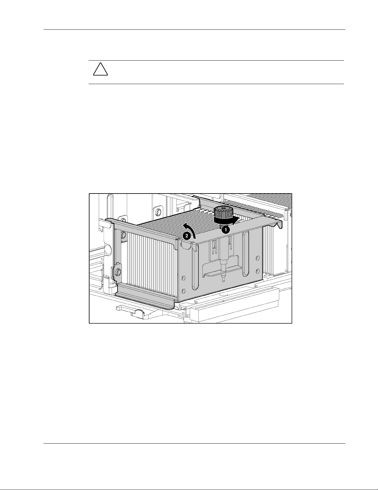
Processor Power Modules
CAUTION: Before installing the Processor Power Module (PPM), make sure that the part
number on the PPM matches the part number on an existing PPM in the system. PPMs with
the same part number may look different, but are functionally equivalent.
1. Power down the server. Refer to “Power ing Down the Server” in this chapter.
2. Extend the server from the rack. Refer to “Extending the Rack from the Server” in this
chapter.
3. Open the rear access panel. Refer to “Op ening and Removing the Rear Access Panel” in
this chapter.
4. Remove the memory board from slot 1. Refer to “Removing a Memory Board” in this
chapter.
5. Remove the processor air baffle. Refer to “Processor A ir Baffle” in t his chapter.
6. Loosen the thumbscrew on the processor retaining bracket (1).
7. Open the processor retaining bracket (2).
Removal and Replacement Procedures
Figure 2-34: Opening the processor retaining bracket
HP ProLiant DL580 Generation 2 Server Maintenance and Service Guide 2-47
Page 65
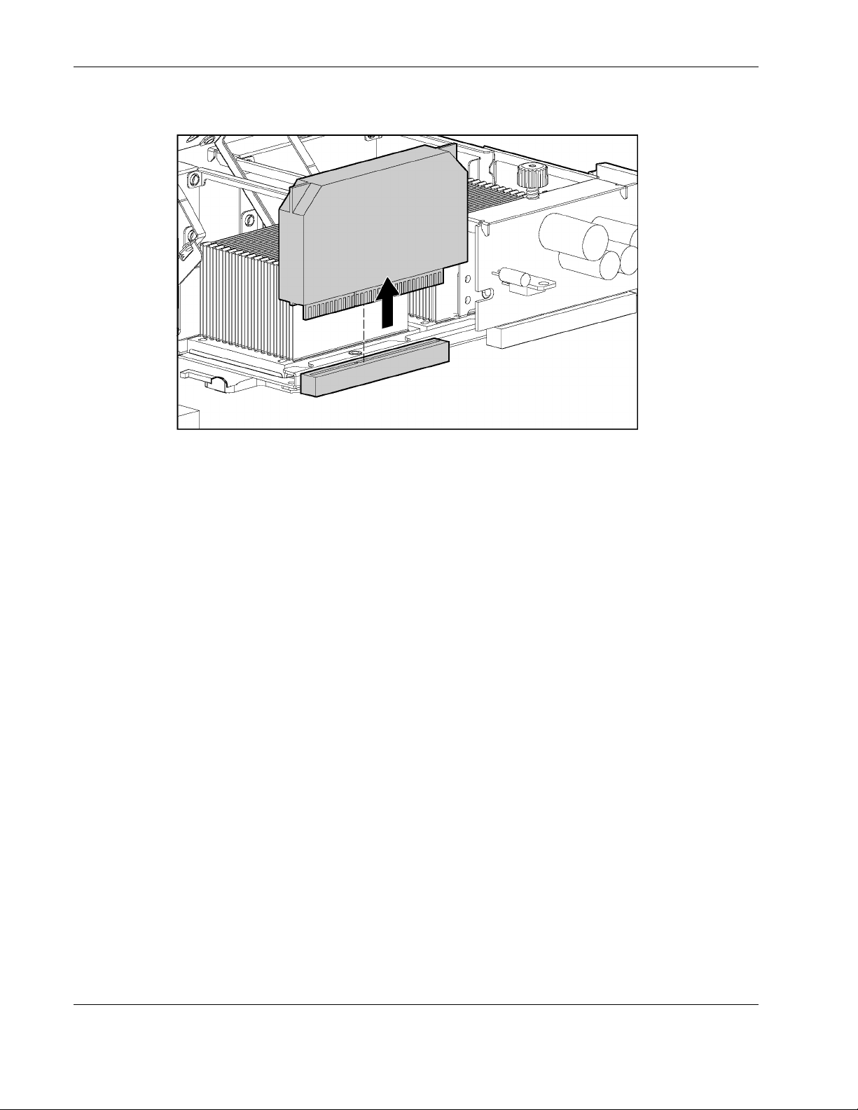
Removal and Replacement Procedures
8. Lift the PPM straight up from its slot.
Figure 2-35: Removing a PPM
Reverse steps 1 through 8 to replace a PPM.
IMPORTANT: When installing a PPM, be sure the key slot in the PPM is aligned with the key in the
slot.
2-48 HP ProLiant DL580 Generation 2 Server Maintenance and Service Guide
Page 66

Processors
Removal and Replacement Procedures
To remove a processor:
1. Power down the server. Refer to “Power ing Down the Server” in this chapter.
2. Extend the server from the rack. Refer to “Extending the Rack from the Server” in this
chapter.
3. Open the rear access panel. Refer to “Op ening and Removing the Rear Access Panel” in
this chapter.
4. Remove the processor air baffle. Refer to “Processor A ir Baffle” in t his chapter.
5. Loosen the thumbscrew on the processor retaining bracket (1).
6. Open the processor retaining bracket (2).
Figure 2-36: Opening the processor retaining bracket
7. Remove the PPM. Refer to “Processor Po wer Modules (PPMs)” in this chapter.
HP ProLiant DL580 Generation 2 Server Maintenance and Service Guide 2-49
Page 67
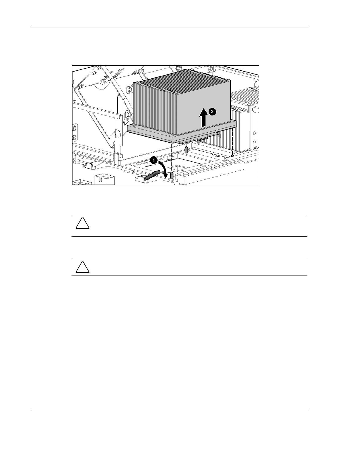
Removal and Replacement Procedures
8. Move the processor-locking lever to the unlocked position (1).
9. Lift the processor/heatsink assembly straight up from its socket (2).
Figure 2-37: Removing the processor/heatsink assembly
Reverse steps 1 through 7 to replace a processor.
CAUTION: The processor is designed to fit one way into the socket. Align the three holes in
the base of the heatsink with the three positioning pins in the retaining bracket to properly seat
the processor.
IMPORTANT: Mixing processor speeds and cache sizes is not supported.
CAUTION: Before closing the processor retaining bracket, be sure that the processor locking
lever is closed. Forcing the bracket shut may damage the processor or the processor socket.
2-50 HP ProLiant DL580 Generation 2 Server Maintenance and Service Guide
Page 68
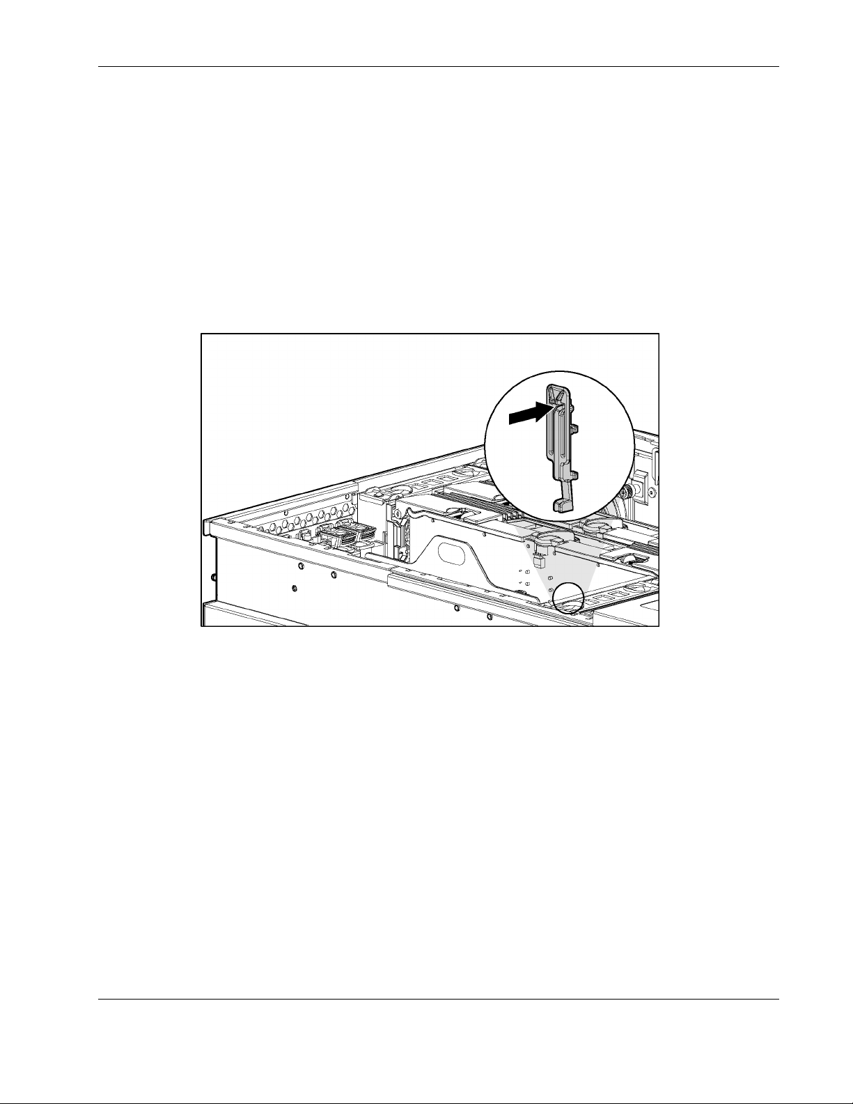
Non-Hot-Plug PCI-X Expansion Boards
To remove a non-hot-plug expansion board:
1. Power down the server. Refer to “Power ing Down the Server” in this chapter.
2. Extend the server from the rack. Refer to “Extending the Rack from the Server” in this
chapter.
3. Open the rear access panel. Refer to “Op ening and Removing the Rear Access Panel” in
this chapter.
4. Disconnect any cables connected to the expansion board.
5. Press the PCI-X retaining clip until it stays in the open position.
Removal and Replacement Procedures
Figure 2-38: Pressing the PCI-X retaining clip
HP ProLiant DL580 Generation 2 Server Maintenance and Service Guide 2-51
Page 69
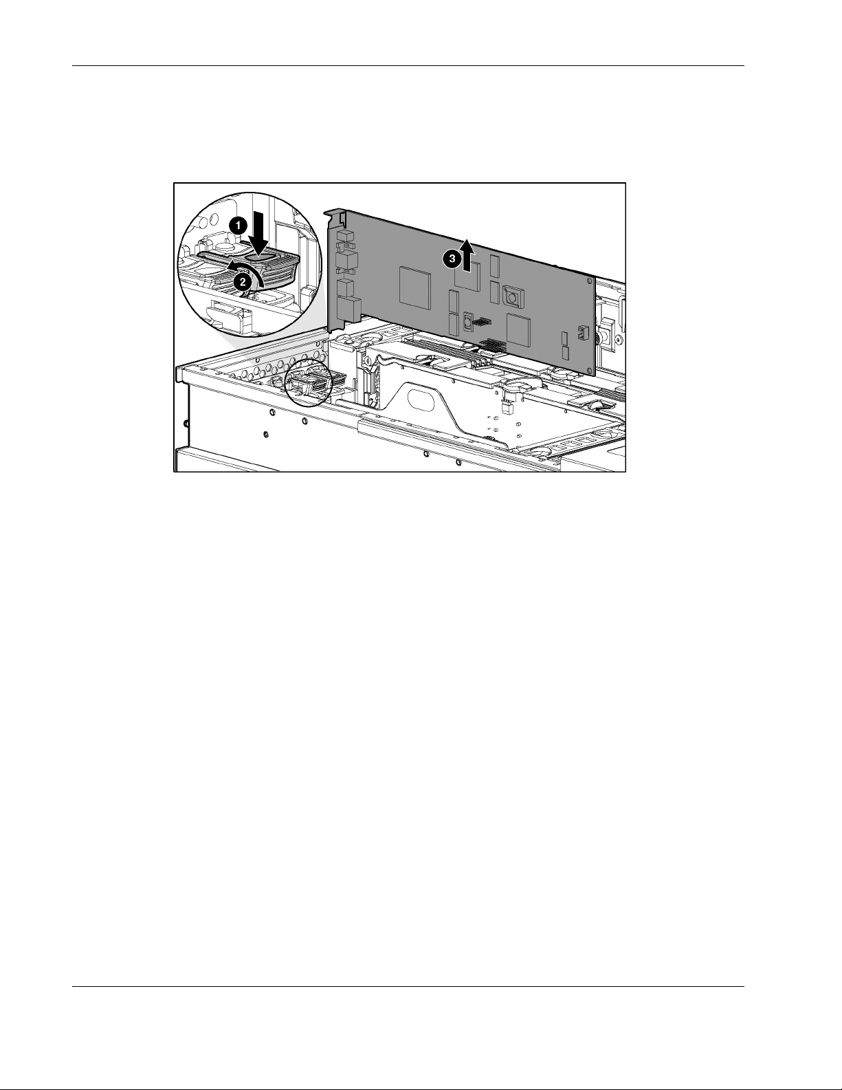
Removal and Replacement Procedures
6. Push the tab on the expansion slot latch (1).
7. Swing the latch back to unlock the expansion board (2).
8. Remove the board from the slot (3).
Figure 2-39: Removing an expansion board from a non-hot-plug slot
Reverse steps 1 through 8 to replace an expansion board.
2-52 HP ProLiant DL580 Generation 2 Server Maintenance and Service Guide
Page 70
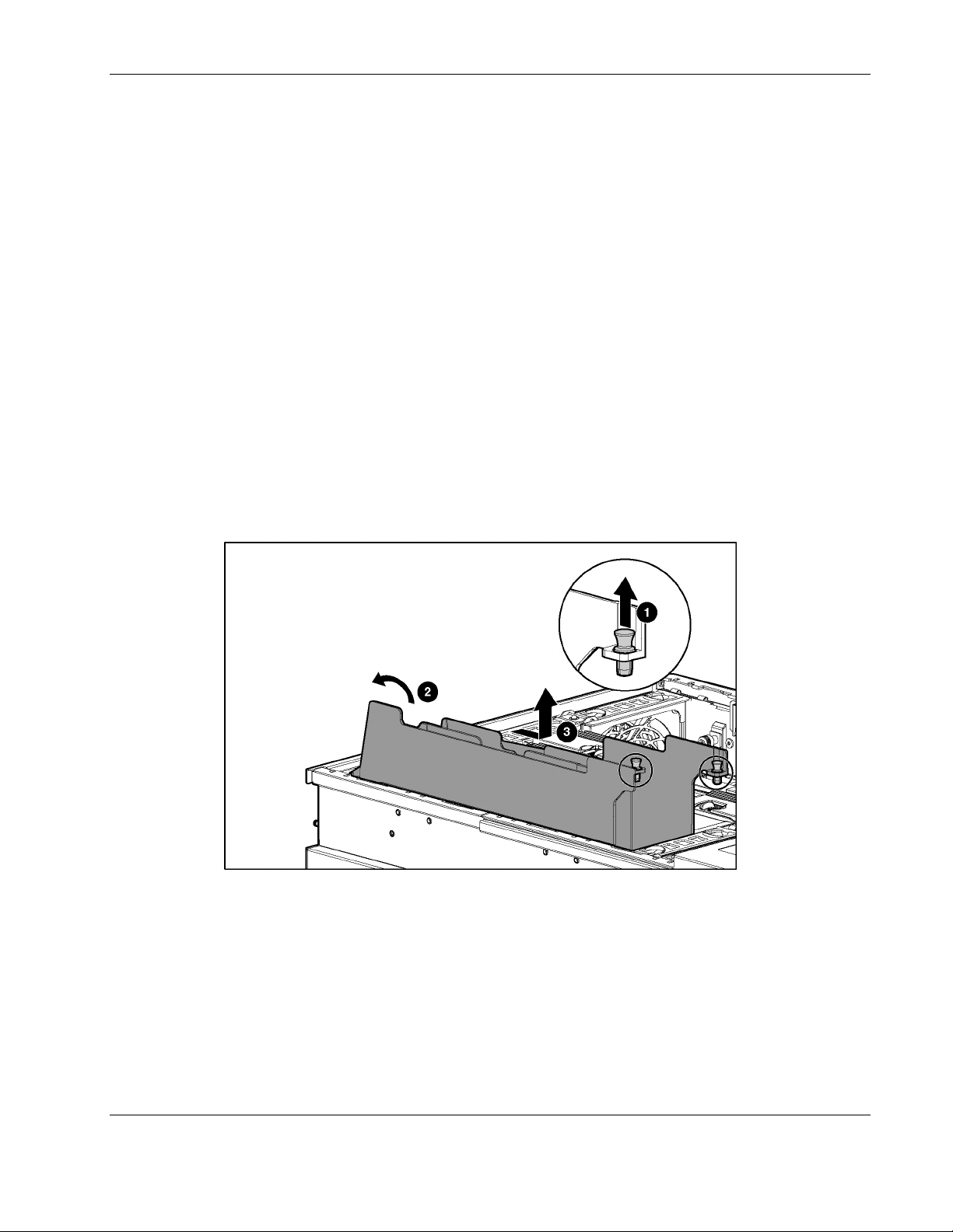
PCI-X Expansion Board Basket
To remove the PCI-X expansion board basket:
1. Power down the server. Refer to “Power ing Down the Server” in this chapter.
2. Extend the server from the rack. Refer to “Extending the Rack from the Server” in this
chapter.
3. Open the rear access panel. Refer to “Op ening and Removing the Rear Access Panel” in
this chapter.
4. Unplug all cables attached to the expansion board at the rear of the server.
5. Remove all PCI-X Hot Plug expansion boards from the basket. Refer to “PCI and PCI-X
Hot Plug Expansion Boards” in this chapter.
IMPORTANT: If no expansion board is installed in PCI-X slot 1, remove the expansion slot cover.
6. Pull up on the two plastic rivets to disengage them from the front fan cage (1).
7. Pull up on the side of the basket at the front of the server and tilt it up to a 45° angle (2).
8. Slide the entire basket toward the front of the server and lift the basket out of the
chassis (3).
Removal and Replacement Procedures
Figure 2-40: Removing the expansion board basket
Reverse steps 1 through 8 to replace the expansion board basket.
HP ProLiant DL580 Generation 2 Server Maintenance and Service Guide 2-53
Page 71
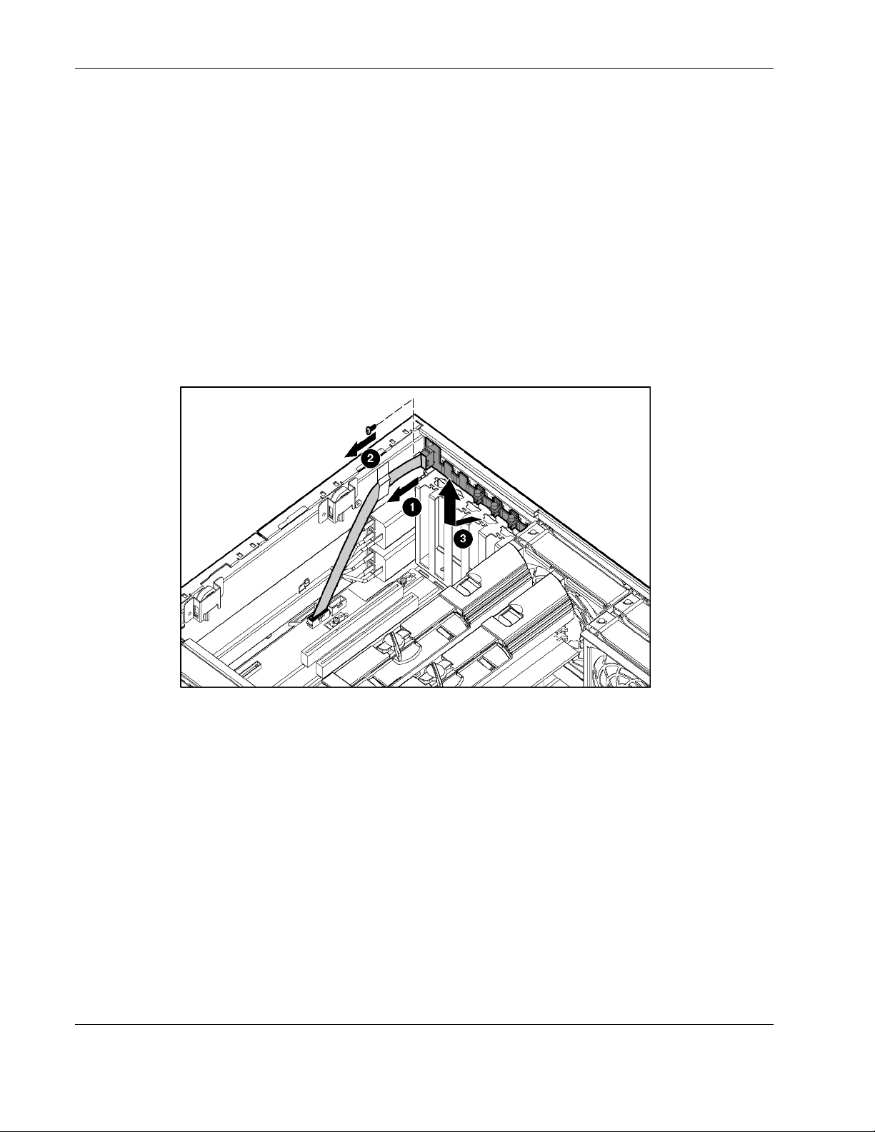
Removal and Replacement Procedures
PCI-X Hot Plug Board
To remove the PCI-X Hot Plugboard:
NOTE: HP recommends that you remove the server from the rack before removing the PCI-X Hot Plug
board.
1. Extend the server from the rack. Refer to “Extending the Rack from the Server” in this
chapter.
2. Power down the server. Refer to “Power ing Down the Server” in this chapter.
3. Open the rear access panel. Refer to “Op ening and Removing the Rear Access Panel” in
this chapter.
4. Remove all PCI-X expansion boards from the basket. Refer to “PCI and PCI-X Hot Plug
Expansion Boards” in this chapter.
Figure 2-41: Removing the PCI-X Hot Plug board
5. Unplug the cable at the PCI-X hot-plug board connector on the system board. Refer to
“System Boar d” in Chapter 4.
6. Open the PCI-X latch and remove the PCI-X slot cover.
7. From the back of the server at the top of the PCI-X slot, press upward and then forward
with your finger to release the PCI-X latch. From inside the server, lift up on the latch
until it unhooks from the back wall of the server.
8. Repeat step 8 for the six PCI-X slots and the PCI-X Hot Plug board will be exposed.
9. Reverse steps 1 through 9 to replace the PCI-X Hot Plug board.
2-54 HP ProLiant DL580 Generation 2 Server Maintenance and Service Guide
Page 72
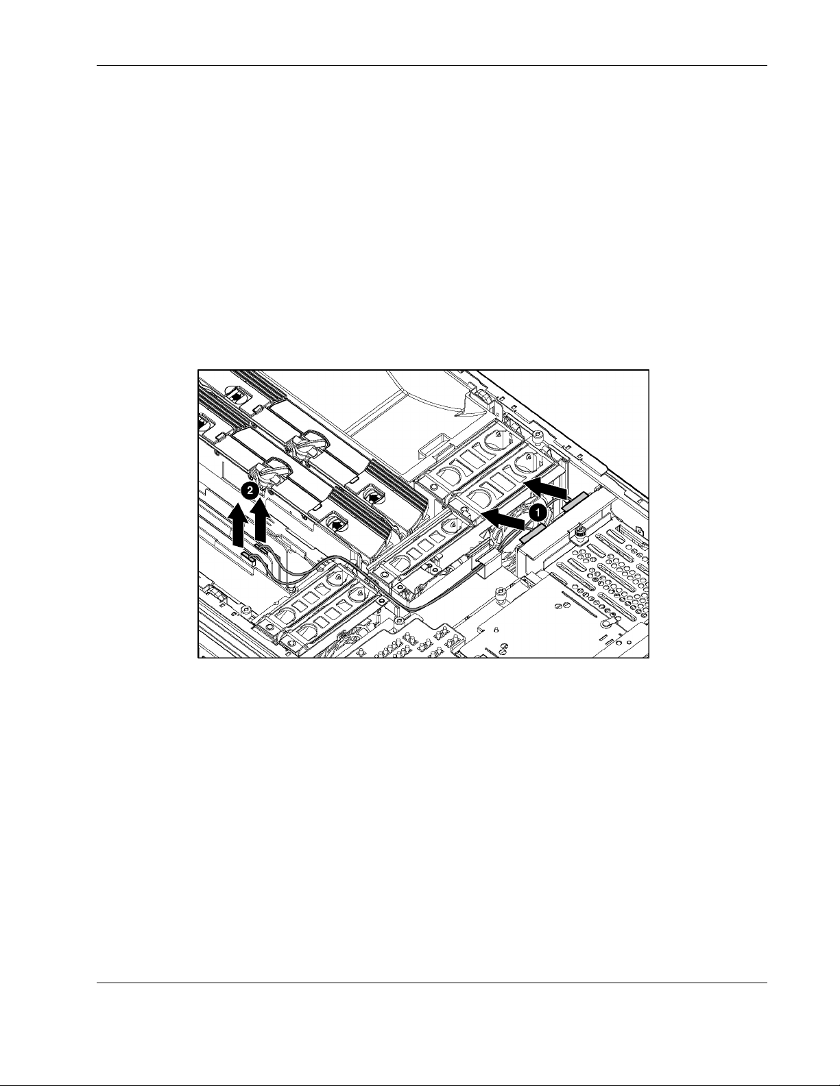
SCSI Cables
To remove the SCSI cables:
1. Power down the server. Refer to “Power ing Down the Server” in this chapter.
2. Extend the server from the rack. Refer to “Extending the Rack from the Server” in this
3. Open the rear access panel. Refer to “Op ening and Removing the Rear Access Panel” in
4. Remove the front access panel. Refer to “Re moving the Front Access Panel” in this
5. Disconnect the SCSI cables from the SCSI backplane (1).
6. Disconnect the SCSI cables from the PCI-X expansion boards (2).
Removal and Replacement Procedures
chapter.
this chapter.
chapter.
Figure 2-42: Disconnecting SCSI cables from the backplane and
expansion boards
Reverse steps 1 through 6 to replace or install the SCSI cables.
HP ProLiant DL580 Generation 2 Server Maintenance and Service Guide 2-55
Page 73
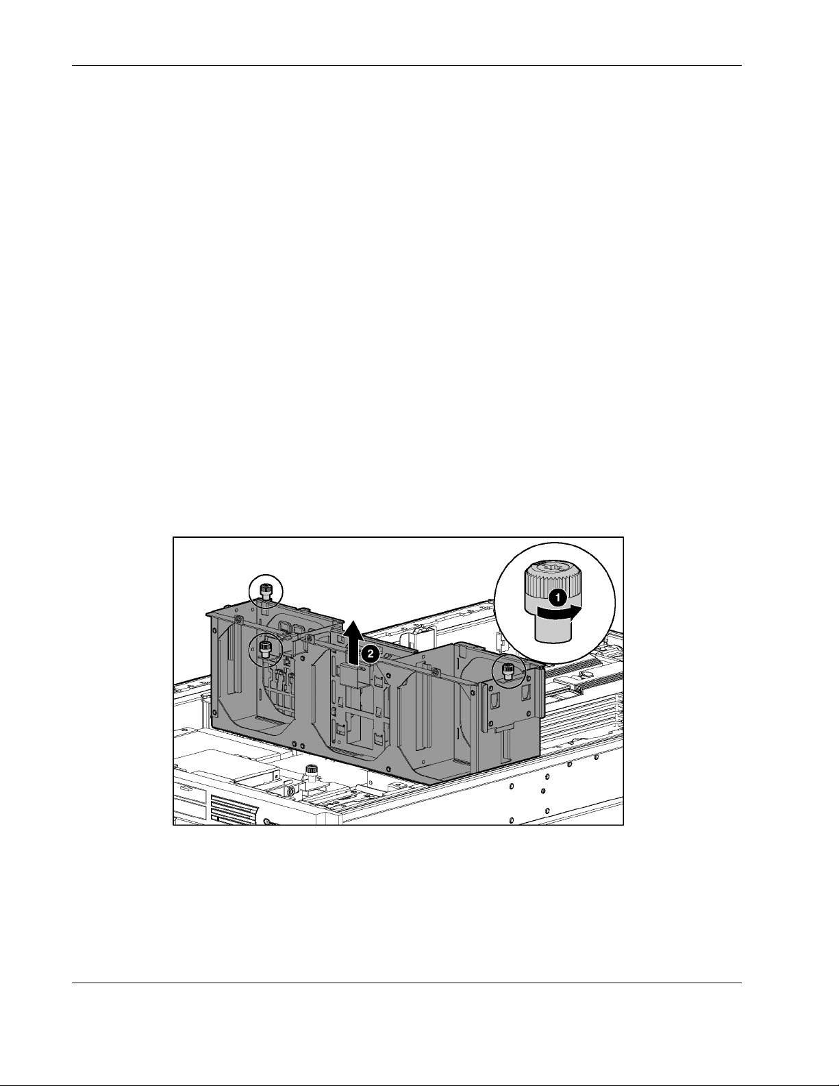
Removal and Replacement Procedures
Front Fan Cage
To remove the front fan cage:
1. Power down the server. Refer to “Power ing Down the Server” in this chapter.
2. Extend the server from the rack. Refer to “Extending the Rack from the Server” in this
chapter.
3. Remove the rear access panel. Refer to “Opening and Removing the Rear Access Panel”
in this chapter.
4. Remove the front access panel. Refer to “Re moving the Front Access Panel” in this
chapter.
5. Remove the hot-plug fans in the front fan cage. Refer to “Hot-Plug Fans” in this chapter.
6. Remove the processor air baffle. Refer to “Processor A ir Baffle” in t his chapter.
7. Remove the memory boards. Refer to “R emoving a Memory Board” in this chapter.
8. Remove the PCI-X expansion boards. Refer to “No n-Hot-Plug PCI-X Expansion Boards”
in this chapter.
9. Remove the PCI-X basket. Refer to “PCI-X Expansion Board Basket” in this ch apter.
10. Remove the SCSI cables. Refer to “SC SI Cables” in this chapter.
11. Loosen the three thumbscrews that secure the front fan cage to the chassis (1).
12. Lift the front fan cage from the chassis (2).
Figure 2-43: Removing the front fan cage
Reverse steps 1 through 12 to replace the front fan cage.
2-56 HP ProLiant DL580 Generation 2 Server Maintenance and Service Guide
Page 74

Pass-Through Board
To remove the pass-through board:
1. Power down the server. Refer to “Power ing Down the Server” in this chapter.
2. Extend the server from the rack. Refer to “Extending the Rack from the Server” in this
chapter.
3. Remove the rear access panel. Refer to “Opening and Removing the Rear Access Panel”
in this chapter.
4. Remove the front access panel. Refer to “Re moving the Front Access Panel” in this
chapter.
5. Remove the front fan cage. Refer to “Front Fan Cage” in this chapter.
6. Loosen the two thumbscrews that secure the pass-through board to the removable media
board and the side chassis wall (1). You may need to use a Torx T-15 screwdriver.
7. Lift the pass-through board straight up and out of the chassis (2).
Removal and Replacement Procedures
Figure 2-44: Removing the pass-through board
Reverse steps 1 through 7 to replace the pass-through board connector.
HP ProLiant DL580 Generation 2 Server Maintenance and Service Guide 2-57
Page 75

Removal and Replacement Procedures
Diagnostics Display Board and Lightpipe
To remove the removable media board:
1. Power down the server. Refer to “Power ing Down the Server” in this chapter.
2. Extend the server from the rack. Refer to “Extending the Server from the Rack” i n this
chapter.
3. Remove the rear access panel. Refer to “Opening and Removing the Rear Access Panel”
in this chapter.
4. Remove the front access panel. Refer to “Re moving the Front Access Panel” in this
chapter.
5. Remove the processor air baffle. Refer to “Processor A ir Baffle” in t his chapter.
6. Remove the front fan cage. Refer to “Front Fan Cage” in this chapter.
7. Remove the pass-through board. Refer to “Pass-Through Board” in this chapter.
8. Eject all devices from the slimline drive bays. Refer to “Slimline Dr ives” in this chapter.
9. Unplug the Power Button/LED cable. Refer to “Power Button/LED Assembly” in this
chapter.
10. Loosen the two thumbscrews holding the removable media board (1).
11. Slide the board to the rear of the unit until it stops, and then lift it up (2).
Figure 2-45: Removing the removable media board
12. Lift the board out gently, being careful of the slimline drive bay connector.
Reverse steps 1 through 12 to replace the removable media board.
2-58 HP ProLiant DL580 Generation 2 Server Maintenance and Service Guide
Page 76

Rear Fan Cage
To remove the rear fan cage:
1. Power down the server. Refer to “Power ing Down the Server” in this chapter.
2. Extend the server from the rack. Refer to “Extending the Rack from the Server” in this
3. Open the rear access panel. Refer to “Op ening and Removing the Rear Access Panel” in
4. Remove the hot-plug fans in the rear fan cage. Refer to “Hot-Plug Fans” in this chapter.
5. Remove the processor air baffle. Refer to “Processor A ir Baffle” in t his chapter.
6. Remove the memory boards. Refer to “R emoving a Memory Board” in this chapter.
7. Loosen the two thumbscrews that secure the rear fan cage to the chassis (1).
8. Remove the rear fan cage from the chassis (2).
Removal and Replacement Procedures
chapter.
this chapter.
Figure 2-46: Removing the rear fan cage
Reverse steps 1 through 8 to replace the rear fan cage.
HP ProLiant DL580 Generation 2 Server Maintenance and Service Guide 2-59
Page 77

Removal and Replacement Procedures
Battery-Backed Write Cache Assembly
The Battery-Backed Write Cache (BBWC) assembly contains the Battery-Backed Write
Cache Enabler (BBWCE), the 5i Plus Memory Module, and the cable that connects the two.
IMPORTANT: The BBWCE and the 5i Plus Memory Module must be removed together, and the cable
must stay connected. Unplugging the cable deletes all the data in the cache.
To remove the BBWC assembly:
1. Power down the server. Refer to “Power ing Down the Server” in this chapter.
2. Extend the server from the rack. Refer to “Extending the Rack from the Server” in this
chapter.
3. Remove the rear access panel. Refer to “Opening and Removing the Rear Access Panel”
in this chapter.
4. Remove the front access panel. Refer to “Re moving the Front Access Panel” in this
chapter.
5. Remove the SCSI cables. Refer to “SC SI Cables” in this chapter.
6. Remove the PCI-X expansion boards. Refer to “No n-Hot-Plug PCI-X Expansion Boards”
in this chapter.
7. Remove the PCI-X expansion board basket. Refer to “PCI-X Expansion Board Basket” in
this chapter.
8. Remove the memory boards. Refer to “R emoving a Memory Board” in this chapter.
9. Remove the processor air baffle. Refer to “Processor A ir Baffle” in t his chapter.
10. Remove the front fan cage. Refer to “Front Fan Cage” in this chapter.
2-60 HP ProLiant DL580 Generation 2 Server Maintenance and Service Guide
Page 78

Removal and Replacement Procedures
11. Using your fingernail, release the latch that connects each side of the 5i Plus Memory
Module to the system board until the module rises away from the system board (1).
CAUTION: Do not disconnect the cable connecting the BBWCE and the 5i Plus Memory
Module.
12. Disengage the BBWCE from the standoffs on the side of the chassis. Remove the
complete assembly from the server by pushing it from under the printed circuit board at
the standoff (2).
Figure 2-47: Removing the BBWC enabler and 5i Plus Memory Module
Reverse steps 1 through 12 to replace the BBWC Enabler and 5i Plus Memory Module.
HP ProLiant DL580 Generation 2 Server Maintenance and Service Guide 2-61
Page 79

Removal and Replacement Procedures
SCSI Backplane
To remove the SCSI backplane:
1. Extend the server from the rack. Refer to “Extending the Rack from the Server” in this
chapter.
2. Power down the server. Refer to “Power ing Down the Server” in this chapter.
3. Unseat all the hot-plug SCSI hard drives and pull them away from the SCSI backplane.
Refer to “Hot -Plug SCSI Hard Drives” i n this chapter.
NOTE: If you plan to take the hard drives out of the drive cage, label them so that they will be
installed in the same slot.
4. Remove the rear access panel. Refer to “Opening and Removing the Rear Access Panel”
in this chapter.
5. Remove the front access panel. Refer to “Re moving the Front Access Panel” in this
chapter.
6. Disconnect any SCSI cables from the SCSI backplane. Refer to “S CSI Cables” i n this
chapter.
7. Loosen the thumbscrew (1).
8. Remove the SCSI backplane from the chassis (2).
Figure 2-48: Removing the SCSI backplane
Reverse steps 1 through 8 to replace the SCSI backplane.
2-62 HP ProLiant DL580 Generation 2 Server Maintenance and Service Guide
Page 80
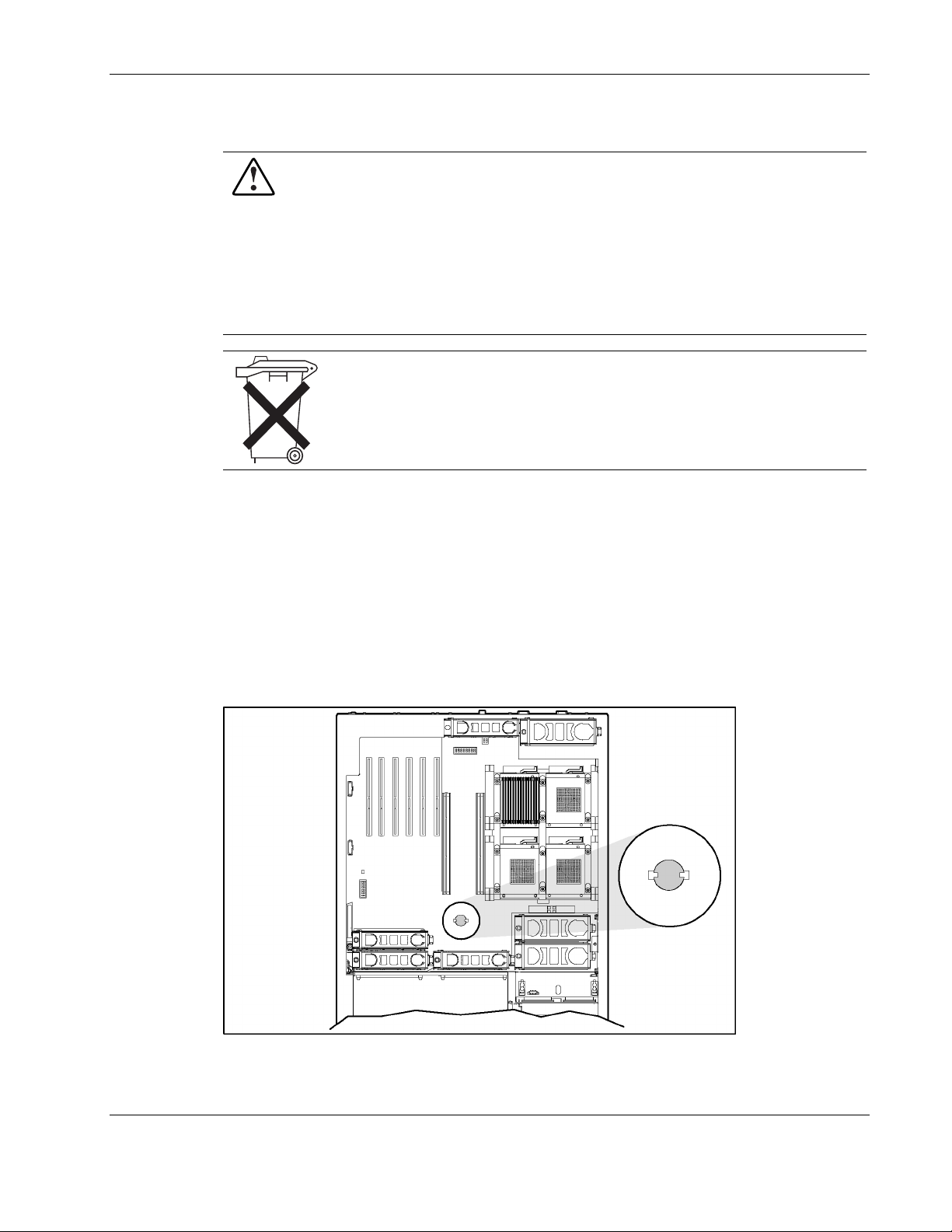
System Battery
To remove the battery:
Removal and Replacement Procedures
WARNING: This server contains an internal lithium manganese dioxide or vanadium
pentoxide battery. A risk of fire and burns exists if the battery pack is not handled
properly. To reduce the risk of personal injury:
• Do not attempt to recharge the battery.
• Do not expose to temperatures higher than 60°C (140°F).
• Do not disassemble, crush, puncture, short external contacts, or dispose of in fire
or water.
• Replace only with the HP spare designated for this server.
CAUTION: Do not dispose of batteries, battery packs, and accumulators with the
general household waste. To forward them to recycling or proper disposal, use the
public collection system or return them to either HP or an authorized service provider.
1. Power down the server. Refer to “Power ing Down the Server” in this chapter.
2. Extend the server from the rack. Refer to “Extending the Rack from the Server” in this
chapter.
3. Open the rear access panel. Refer to “Op ening and Removing the Rear Access Panel” in
this chapter.
4. Remove the memory boards. Refer to “R emoving a Memory Board” in this chapter.
5. Locate the battery on the system board.
Figure 2-49: Locating the battery on the system board
HP ProLiant DL580 Generation 2 Server Maintenance and Service Guide 2-63
Page 81

Removal and Replacement Procedures
6. Remove the battery (part number 153099-001) from the system board.
Figure 2-50: Removing the battery from the system board
Reverse steps 1 through 6 to replace the battery.
CAUTION: Loss of BIOS settings occurs when the system battery is removed. BIOS settings
must be reconfigured whenever the battery is replaced. Power up the server and run RBSU.
2-64 HP ProLiant DL580 Generation 2 Server Maintenance and Service Guide
Page 82

System Board
To remove the system board:
1. Power down the server. Refer to “Power ing Down the Server” in this chapter.
2. Remove all power supplies. Refer to “H ot-Plug Power Supply” in this chapter.
3. Unseat all the hot-plug SCSI hard drives. Refer to “Hot-Plug SCSI Hard Drives” in this
4. Extend the server from the rack. Refer to “Extending the Rack from the Server” in this
5. Remove the rear access panel. Refer to “Opening and Removing the Rear Access Panel”
6. Remove the front access panel. Refer to “Re moving the Front Access Panel” in this
7. Remove the front fan cage. Refer to “Front Fan Cage” in this chapter.
8. Remove the rear fan cage. Refer to “R ear Fan Cage” i n this chapter.
Removal and Replacement Procedures
chapter. Label the individual hard drives if they will be removed from the drive cage, so
that you can replace them in their correct location.
chapter. Although not required, HP recommends removing the server from the rack for
best performance. See “R emoving the Server from the Rack” in this chapter.
in this chapter.
chapter.
9. Remove the pass-through board. Refer to “Pass-Through Board” in this chapter.
10. Remove the SCSI backplane. Refer to “ SCSI Backplane” in this chapter.
11. Remove the BBWC assembly. Refer to “Ba ttery-Backed Write Cache Assembly” in this
chapter.
HP ProLiant DL580 Generation 2 Server Maintenance and Service Guide 2-65
Page 83
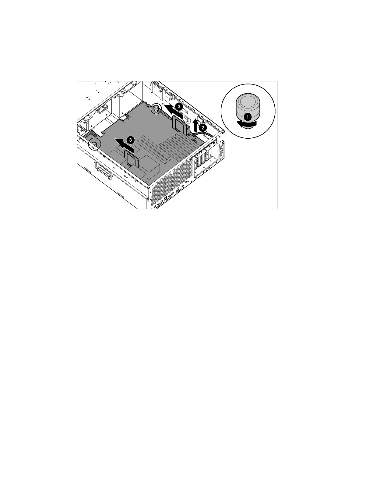
Removal and Replacement Procedures
12. Unscrew the system board thumbscrews (1).
13. Disconnect the PCI-X board cable (2).
14. Slide the system board toward the front of the unit (3).
Figure 2-51: Unscrewing the thumbscrews and sliding the system
board
IMPORTANT: When handling the system board, place your hands only on the two handles.
2-66 HP ProLiant DL580 Generation 2 Server Maintenance and Service Guide
Page 84
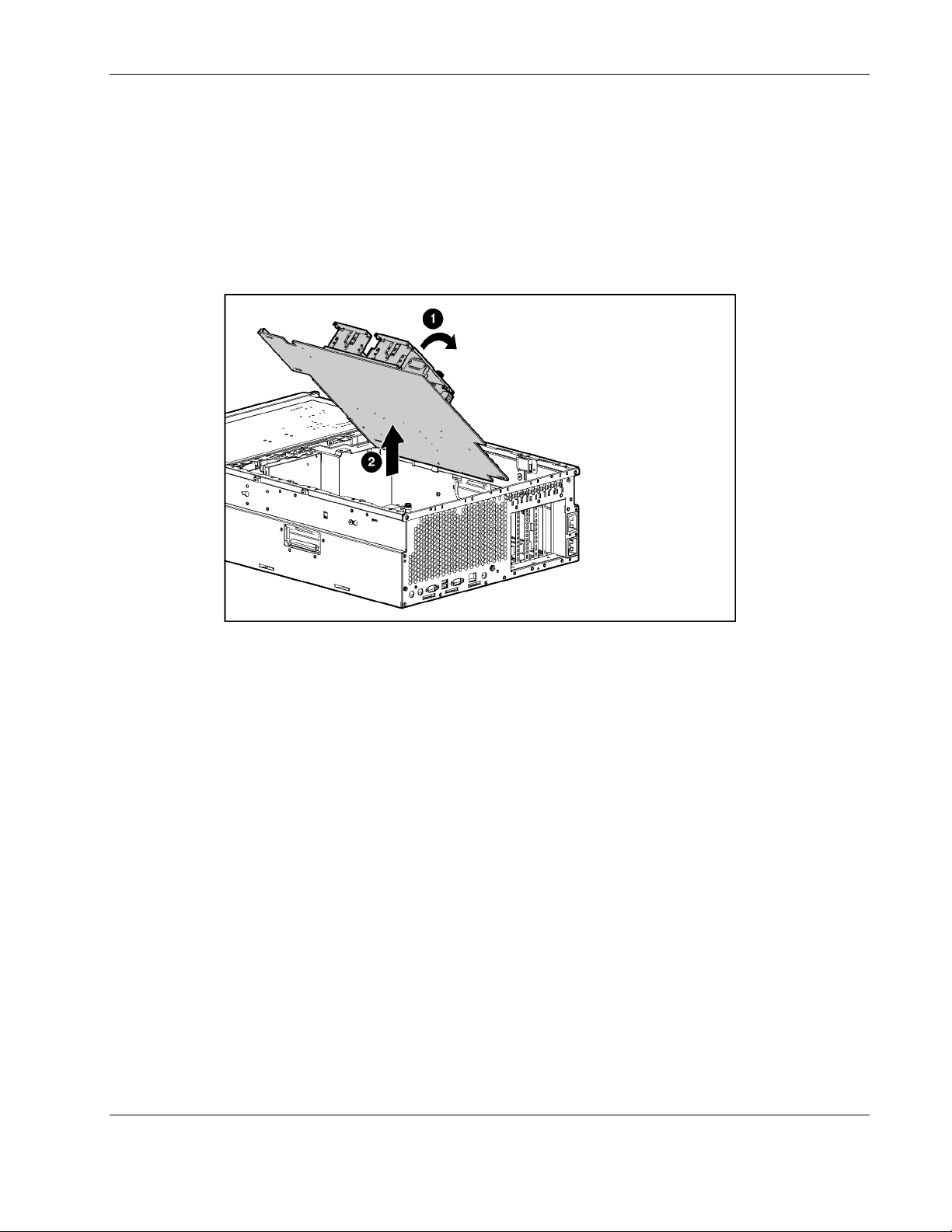
Removal and Replacement Procedures
15. Grasping the two handles, lift the side with the processor handles first, tilting the board to
a 45° angle (1).
16. Lift the entire system board out of the chassis (2).
17. Transfer the processors and PPMs to the replacement system board. Be sure to put them
back in the same slots.
18. Check the SW4, SW7, and SW8 switch settings on the old board against the settings in
chapter 4 to be sure that they are in the correct positions.
Figure 2-52: Removing the system board from the chassis
Reverse steps 1 through 18 to replace the system board.
IMPORTANT: The server serial number must be re-entered through RBSU after replacing the system
board. Refer to the “Re-entering the Server Serial Number” section.
HP ProLiant DL580 Generation 2 Server Maintenance and Service Guide 2-67
Page 85

Removal and Replacement Procedures
AC Filter Cable Assembly
The AC filter cable assembly consists of two cables leading from separate power supply input
connectors near the front of the chassis and ending in an AC filter and inlets at the rear of the
chassis.
To remover the AC filter cable:
1. Power down the server. Refer to “Power ing Down the Server” in this chapter.
2. Remove all power supplies. Refer to “H ot-Plug Power Supplies” in this chapter.
3. Label the individual hard drives so that you can replace them in their correct location.
4. Remove all the hot-plug SCSI hard drives. Refer to “Hot-Plug SC SI Hard Drives” in this
chapter.
5. Extend the server from the rack. Refer to “Extending the Rack from the Server” in this
chapter.
6. Remove the rear access panel. Refer to “Opening and Removing the Rear Access Panel”
in this chapter.
7. Remove the front access panel. Refer to “Re moving the Front Access Panel” in this
chapter.
8. Remove all hot-plug fans in the front and rear fan cages. Refer to “Hot-Plug Fans” in this
chapter.
9. Remove the processor air baffle. Refer to “Processor A ir Baffle” in t his chapter.
10. Remove all PPMs. Refer to “Processor Power Modules (PPMs)” in this chapter.
11. Remove all processors. Refer to “Proces sors” in this chapter.
12. Remove the memory boards. Refer to “R emoving a Memory Board” in this ch apter.
13. Remove the PCI-X expansion boards. Refer to “No n-Hot-Plug PCI-X Expansion Boards”
in this chapter.
14. Remove the PCI-X basket. Refer to “PCI-X Expansion Board Basket” in this ch apter.
15. Remove the SCSI cables. Refer to “SC SI Cables” in this chapter.
16. Remove the front fan cage. Refer to “Front Fan Cage” in this chapter.
17. Remove the rear fan cage. Refer to “R ear Fan Cage” i n this chapter.
18. Remove the pass-through board. Refer to “Pass-Through Board” in this chapter.
19. Remove the SCSI backplane. Refer to “ SCSI Backplane” in this chapter.
20. Remove the BBWC assembly. Refer to “Ba ttery-Backed Write Cache Assembly” in this
chapter.
21. Remove the system board. Refer to “S ystem Board” l ocated in this chapter.
2-68 HP ProLiant DL580 Generation 2 Server Maintenance and Service Guide
Page 86
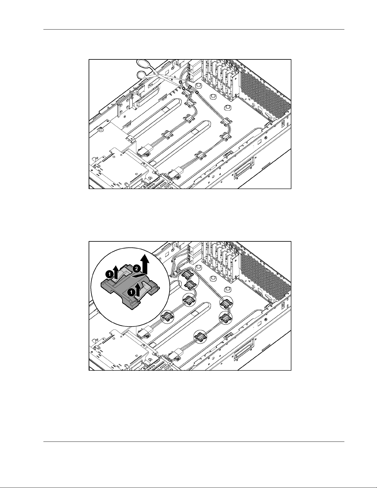
Removal and Replacement Procedures
22. Cut the four tie-wraps securing the AC filter cable to the chassis.
Figure 2-53: Cutting the cable tie-wraps
23. Remove the seven cable clips:
a. Lift to disengage the cable clip (1).
b. Slide the clip forward, and lift it off the chassis (2).
Figure 2-54: Removing the cable clips
HP ProLiant DL580 Generation 2 Server Maintenance and Service Guide 2-69
Page 87
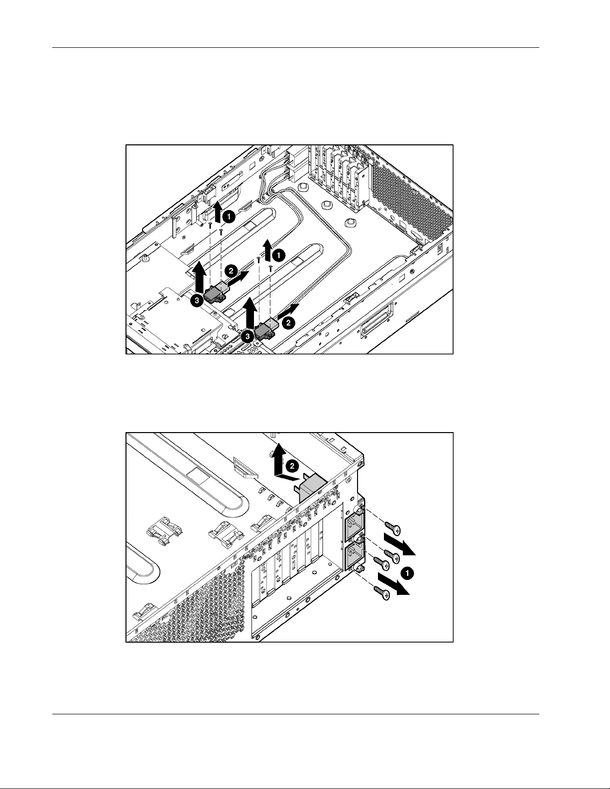
Removal and Replacement Procedures
24. Use the Torx T-15 tool or screwdriver to remove the eight screws that secure the power
supply connectors to the chassis bottom (1).
25. Remove the cords from the connectors (2).
26. Remove the connectors from the server (3).
Figure 2-55: Removing the power supply connectors
27. Use the Torx T-15 tool or a screwdriver to remove the four screws that secure the AC
filter cable assembly to the rear chassis wall (1).
28. Slide the assembly into the chassis, and then lift the assembly out of the chassis (2).
Figure 2-56: Removing the AC filters
Reverse steps 1 through 28 to replace the AC filter cable assembly.
2-70 HP ProLiant DL580 Generation 2 Server Maintenance and Service Guide
Page 88

Re-entering the Server Serial Number
After replacing the system board or clearing the NVRAM, the server serial number must be
re-entered.
Removal and Replacement Procedures
1. During the server startup sequence, press the F9 key to access RBS
U.
2. Select the System Options menu.
3. Select Serial Number. The following wa
WARNING! WARNING! WARNING! The serial number is loaded into the
system during the manufacturing process and should NOT be
modified. This option should ONLY be used by qualified service
personnel. This value should always match the serial number
sticker located on the chassis.
rning is displayed:
Press the Enter key to clear the warning.
4. Enter the serial number and press the Enter key.
5. Press the Escape key to close the menu.
6. Press
7. Press the F10 key to confir
the Escape key to exit RBSU.
m exiting RBSU. The server will automatically reboot.
HP ProLiant DL580 Generation 2 Server Maintenance and Service Guide 2-71
Page 89

Diagnostic Tools
This chapter is an overview of software and firmware diagnostic tools that are available for
configuring, monitoring, and managing the HP ProLiant DL580 Generation 2 servers.
3
HP ProLiant DL580 Generation 2 Server Maintenance and Service Guide 3-1
Page 90

Diagnostic Tools
Use the tools in Table 3-1 to diagnose problems, test hardware, and monitor and manage the
HP ProLiant DL580 Generation 2 server operations.
Table 3-1: Diagnostic Tools
Tool Description How to run the tool
Array Diagnostics Utility (ADU) ADU is designed to run on all
ProLiant systems that support HP
array controllers. ADU collects
information about the array
controllers in the system and
generates a list of detected
problems.
Automatic Server Recovery-2
(ASR-2)
Diagnostics Diagnostics tests and verifies
Insight Manager 7 Insight Manager 7 is a client/server
Integrated Lights-Out (iLO) iLO is a remote management port
ASR-2 automatically restarts the
server after a catastrophic operating
system failure.
With ASR-2, you have two recovery
options:
• Available Recovery provides
software error recovery and
environmental recovery.
• Unattended Recovery logs the
error information to the IML,
resets the server, and tries to
restart the operating system.
operation of HP hardware. If
Diagnostics finds a hardware failure,
it isolates the replaceable part, if
possible.
application used to remotely manage
HP hardware in a network
environment. Insight Manager
reports hardware fault conditions
(both failure and pre-failure) and
collects data for reporting and
graphing.
that can be accessed through a
dedicated Lights-Out port on the rear
panel of the server. Accessed
through a standard browser from
anywhere, the iLO capabilities will
not require any unique software
applications to use.
For a list of HP servers that support
ADU, follow the support link on
product website at www.hp.com.
For a complete list of ADU error
messages, refer to the HP Servers
Troubleshooting Guide.
Run RBSU and set ASR-2 to enable
this tool.
Access Diagnostics when POST
detects a system configuration error.
For a complete list of POST error
messages, refer to the HP Servers
Troubleshooting Guide. Diagnostics
can be run from the SmartStart CD
or downloaded by following the
support link on the product website
at www.hp.com.
For more information on viewing and
printing the event list, refer to the
Management CD, the Insight
Manager User Guide, or in the HP
ProLiant DL580 Generation 2 Server
Setup and Installation Guide.
For more information on iLO, refer to
the Integrated Lights-Out User Guide
on the Documentation CD.
3-2 HP ProLiant DL580 Generation 2 Server Maintenance and Service Guide
Page 91

Table 3-1: Diagnostic Tools
Tool Description How to run the tool
Diagnostic Tools
Survey Utility Survey Utility gathers critical
hardware and software information
on servers running Microsoft
Windows NT, Novell NetWare, SCO
OpenServer, or SCO Unixware
operating systems.
If a significant change occurs
betwe
a-gathering intervals,
en dat
the survey utility marks the previous
information and overwrites the
survey text files to reflect the latest
changes in the configuration.
Integrated Management Log (IML) The IML is a log of system events
such as system failures or nonfatal
error conditions. View events in the
IML from within:
• Insight Manager 7
• Survey Utility
• Operating system-specific IML
utilities
ROM-Based Setup Utility (RBSU)) RBSU configures the hardware
installed in or connected to the
server. Specifically, it can:
• Store configuration information
in nonvolatile memory
• Manage memory installation,
processor upgrades, network
interface cards and mass
storage devices
• Assist in installing an operating
system
• Configure ports and IRQs, if
required
Install the Survey Utility from the
SmartStart CD, the Integration
Mainte
e Utility, or the
nanc
Management CD.
The IML requires HP operating
system management drivers. Refer
to the SmartStart CD for instructions
on installing the appropriate drivers.
Run RBSU by pressing the F9 key
during POST.
ROMPaq Utility The ROMPaq Utility checks the
system and provides a choice of
Run this utility from the SmartStart
CD incl
d with the server.
ude
available ROM revisions and
controller firmware.
SmartStart Diskette Builder The SmartStart Diskette Builder is a
utility that uses data stored on the
Run the diskette builder tool from the
SmartStart CD.
SmartStart CD to create support
diskettes. You can create support
diskettes for specific configuration
needs or for software that cannot be
used directly from the
SmartStart CD.
HP ProLiant DL580 Generation 2 Server Maintenance and Service Guide 3-3
Page 92

This chapter explains the location and function of system connectors, internal and external
LEDs, and system switches.
Connectors
Use this section to identify system connectors for service procedures.
4
Connectors, LEDs, and Switches
HP ProLiant DL580 Generation 2 Server Maintenance and Service Guide 4-1
Page 93

Connectors, LEDs, and Switches
Rear Panel
Figure 4-1 and Table 4-1 illustrate the components located on the rear panel.
Figure 4-1: Rear panel components
Table 4-1: Rear Panel Components
Item Description
1 Keyboard connector
2 Mouse connector
3 Video connector
4 USB connector 1
5 USB connector 2
6 Serial connector
7 Integrated Lights-Out Network connector
8 Rear Unit Identification LED switch
9 Torx T-15 tool
10 PCI-X Hot Plug slots 3 through 6
11 PCI-X non-hot-plug slot 2 (NIC with RJ-45 Ethernet connector)
12 PCI-X non-hot-plug slot 1
13 AC inlet (primary)
14 AC inlet (secondary)
4-2 HP ProLiant DL580 Generation 2 Server Maintenance and Service Guide
Page 94

System Board
Figure 4-2 and Table 4-2 illustrate the connectors located on the system board.
Figure 4-2: System board connectors
Table 4-2: System Board Connectors
Connectors, LEDs, and Switches
Item Description Item Description Item Description
1 Non-hot-plug expansion slot 1 13 Processor 1 25 Hot-plug fan 3
2 Non-hot-plug expansion slot 2 14 Processor socket 2 26 Hot-plug fan 1
3 Hot-plug slot 3 15 PPM slot 2 27 Hot-plug fan 2
4 Hot-plug slot 4 16 PPM slot 3 28 Pass-through board connector
5 Hot-plug slot 5 17 Processor socket 3 29
6 Hot-plug slot 6 18 Processor socket 4 30
7 Memory board slot 2 19 PPM slot 4 31 System ID switch (SW7)
Integrated Lights-out diagnostic
8
LEDs
9 Memory board slot 1 21 5i Plus Memory Module 33
10 Hot-plug fan 4 22 Hot-plug fan 6 34
11 Hot-plug fan 7 23 Hot-plug fan 5
12 Power Processor Module (PPM) 1 24 Battery
Battery-backed write cache
20
enabler (optional)
Non-Maskable Interrupt (NMI)
switch
Configuration maintenance
switch (SW4)
Integrated Lights-Out override
32
switch (SW8)
30-pin Remote Insight Lights-
Out Edition II Board connector
PCI-X Hot Plug board
connector
HP ProLiant DL580 Generation 2 Server Maintenance and Service Guide 4-3
Page 95

Connectors, LEDs, and Switches
SCSI Backplane Board
Figure 4-3: SCSI backplane board connectors
Table 4-3: SCSI Backplane Board Connectors
Item Description
SCSI channel B
1
SCSI simplex/duplex switch
2
SCSI channel A
3
4-4 HP ProLiant DL580 Generation 2 Server Maintenance and Service Guide
Page 96
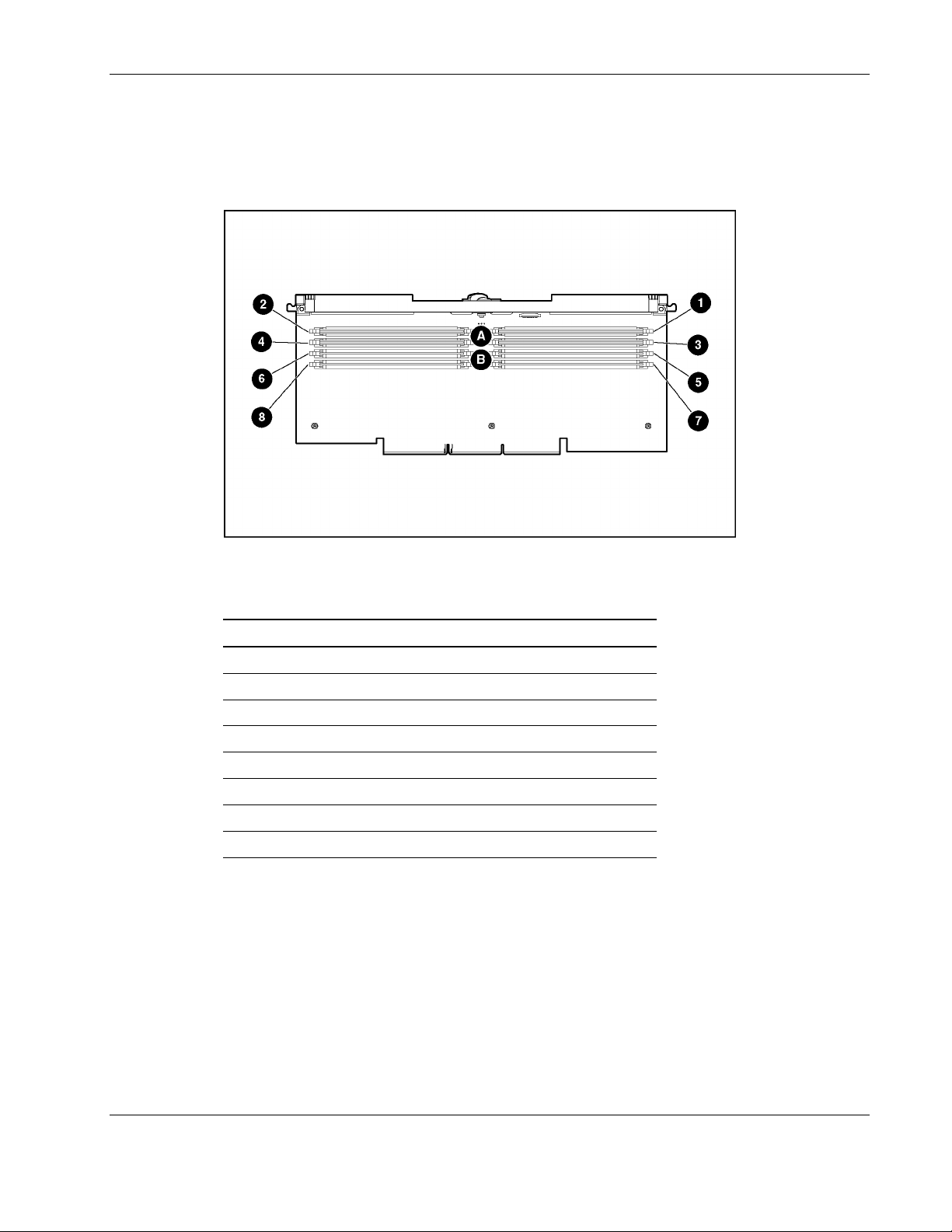
Memory Board
Figure 4-4 and Table 4-4 illustrate the connectors and DIMM banks located on the memory
board.
Connectors, LEDs, and Switches
Figure 4-4: Memory board connectors and DIMM banks
Table 4-4: Memory Board Connectors and DIMM Banks
Item Description
1 DIMM slot 1, bank A (populated)
2 DIMM slot 2, bank A (populated)
3 DIMM slot 3, bank A (populated)
4 DIMM slot 4, bank A (populated)
5 DIMM slot 5, bank B
6 DIMM slot 6, bank B
7 DIMM slot 7, bank B
8 DIMM slot 8, bank B
HP ProLiant DL580 Generation 2 Server Maintenance and Service Guide 4-5
Page 97

Connectors, LEDs, and Switches
LEDs
The ProLiant DL580 Generation 2 server contains several sets of LEDs that indicate the
status and settings of hardware components. This section discusses the types and locations of
the following LEDs:
Front panel
•
QuickFind Diagnostic display
•
Hot-plug SCSI hard drive
•
Hot-plug fans
•
Hot-plug power supplies
•
PCI-X hot-plug
•
Memory board
•
Processors and PPMs
•
Internal Diagnostic Display
•
Interlock Status
•
4-6 HP ProLiant DL580 Generation 2 Server Maintenance and Service Guide
Page 98
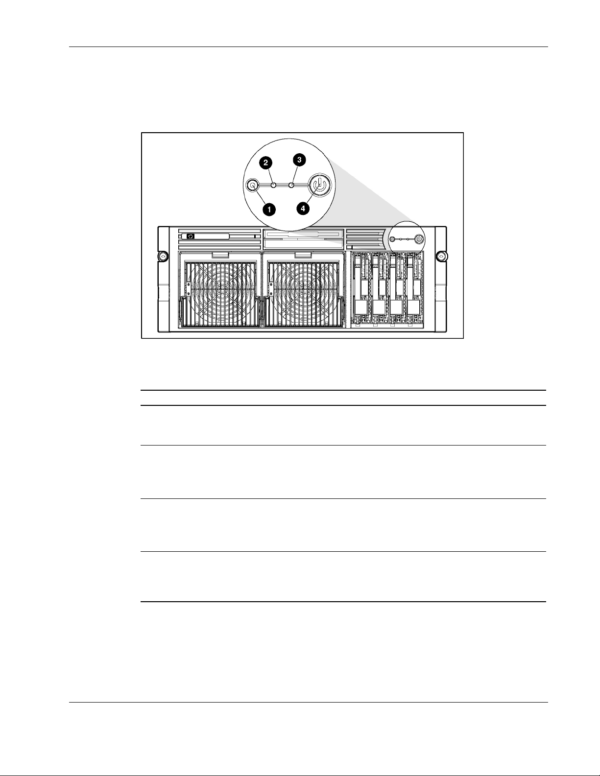
Front Panel
Connectors, LEDs, and Switches
The front panel has four LEDs that indicate the status of the server. Figure 4-5 and Table 4-5
identify the location and status of each of the LEDs.
Figure 4-5: Front panel LEDs
Table 4-5: Front Panel LEDs
Item Description Status
1 Unit ID Blue = Activated
Blue flashing = System being managed remotely
Off = Deactivated
2 Internal health Green = Normal
Red = System critical
Amber = System degraded
Off = System off
3 External health Green = Normal
Red = Critical power supply failure
Amber = Redundant power supply failure
Off = System off
4 Power Green = On
Amber = Off (auxiliary power only)
Off = Power cord not attached to the server or power
supply failure
HP ProLiant DL580 Generation 2 Server Maintenance and Service Guide 4-7
Page 99
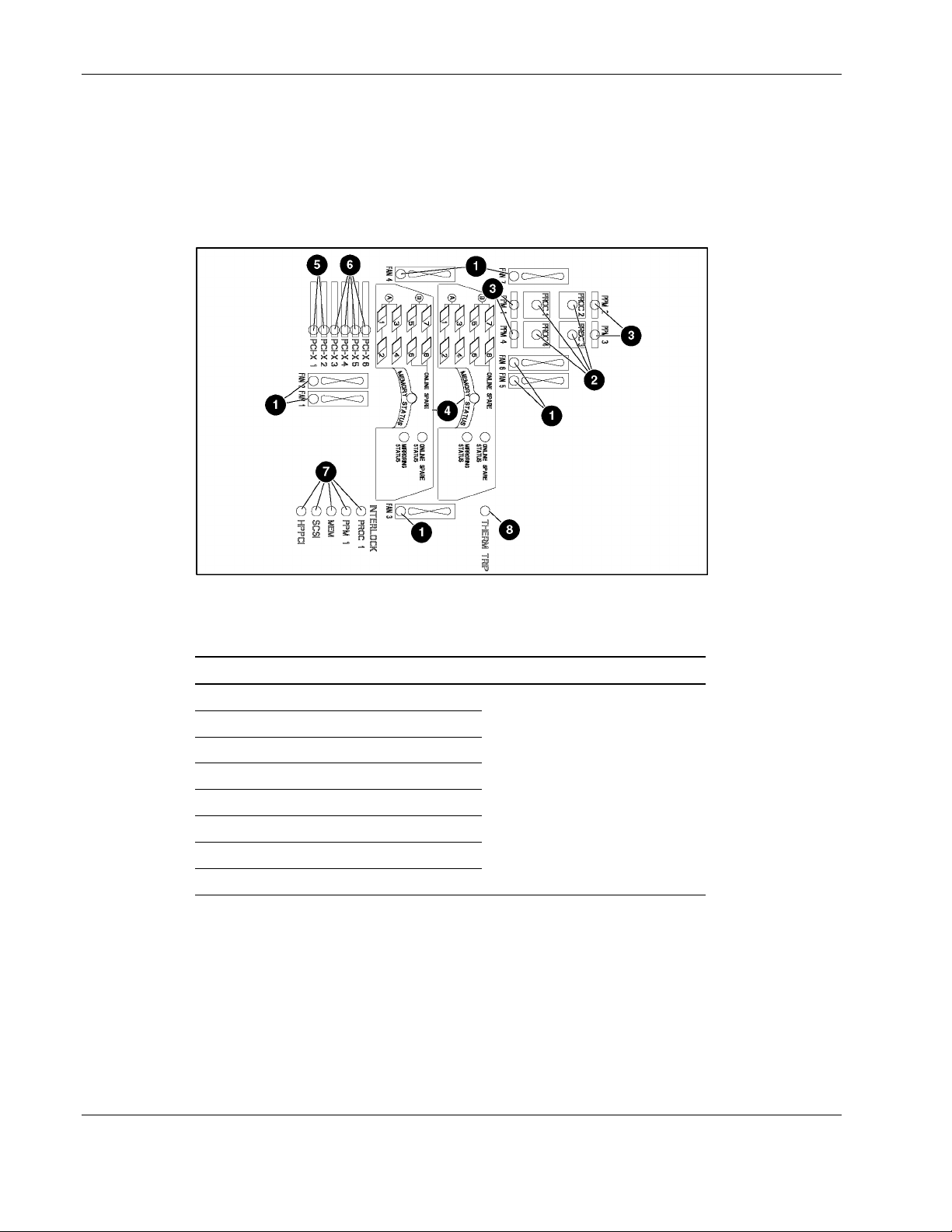
Connectors, LEDs, and Switches
QuickFind Diagnostic Display
A new feature on the ProLiant DL580 Generation 2 server set of is the LEDs that are located
on the front access panel. These LEDs enable you to quickly diagnosis a problem with a
component in the server simply by referring to the top of the system. Figure 4-6 and
Table 4-6 identify the location and status of each of the LEDs.
Figure 4-6: QuickFind Diagnostic Display LEDs
Table 4-6: QuickFind Diagnostic Display LEDs
Item Description Status
1 Hot-plug fans
2 Processors
3 PPMs
4 Memory
5 Non-hot-plug PCI-X
6 Hot-plug PCI-X
7 Interlock
8 Therm trip
Amber = failure detected
Off = Normal
4-8 HP ProLiant DL580 Generation 2 Server Maintenance and Service Guide
Page 100

Interlock Status
Improperly seated components in the interlock chain cause the LED associated with the fault
origination point to illuminate on the system board. Figure 4-7 and Table 4-7 identify the
location and status of each of the LEDs.
NOTE: Interlock components are required for the system to power up.
IMPORTANT: ProLiant DL580 Generation 2 servers are not equipped with chassis door or access
panel interlocks.
Connectors, LEDs, and Switches
Figure 4-7: Interlock LEDs
Table 4-7: Interlock LEDs
Item Name Status Description
1 HPPCI
2 SCSI
3 Mem
4 PPM 1
Amber PCI Hot Plug PCA cable or PCI-X Hot Plug board
not installed properly
Off Normal
Amber SCSI backplane not seated properly
Off Normal
Amber No memory boards detected; memory boards not
installed properly
Off Normal
Amber Processor Power Module 1 not installed properly
Off Normal
Amber Processor 1 not installed properly 5 Proc 1
Off Normal
HP ProLiant DL580 Generation 2 Server Maintenance and Service Guide 4-9
 Loading...