

HP ProLiant DL580 G9 User Manual

HPE ProLiant DL580 Gen9 Server
Abstract
This document is for the person who installs, administers, and troubleshoots servers and storage systems. Hewlett Packard Enterprise
Part Number: 799243-002
May 2016
Edition: 3
User Guide
assumes you are qualified in the servicing of computer equipment and trained in recognizing hazards in products with hazardous energy
levels.

© Copyright 2015, 2016 Hewlett Packard Enterprise Development LP
The information contained herein is subject to change without notice. The only warranties for Hewlett Packard Enterprise products and services
are set forth in the express warranty statements accompanying such products and services. Nothing herein should be construed as constituting
an additional warranty. Hewlett Packard Enterprise shall not be liable for technical or editorial errors or omissions contained herein.
Microsoft® and Windows® are either registered trademarks or trademarks of Microsoft Corporation in the United States and/or other countries.
Intel® and Xeon® are trademarks of Intel Corporation in the U.S. and other countries.
Linux® is the registered trademark of Linus Torvalds in the U.S. and other countries.
Red Hat® is a registered trademark of Red Hat, Inc. in the United States and other countries.
VMware is a registered trademark or trademark of VMware, Inc. in the United States and/or other jurisdictions.

Contents
Component identification .......................................................................................................................... 6
Front panel components ........................................................................................................................................... 6
Front panel LEDs and buttons .................................................................................................................................. 7
Systems Insight Display ........................................................................................................................................... 8
Rear panel components ........................................................................................................................................... 9
Power supply LED .................................................................................................................................................. 10
I/O board components ............................................................................................................................................ 11
System maintenance switch ........................................................................................................................ 12
NMI jumper .................................................................................................................................................. 12
SPI board components ........................................................................................................................................... 13
Power daughter board components ....................................................................................................................... 14
DIMM slot locations ................................................................................................................................................ 15
Processors and memory cartridges ........................................................................................................................ 16
DIMM fault LEDs .................................................................................................................................................... 17
DIMM fault identification button .............................................................................................................................. 18
Memory error LEDs ................................................................................................................................................ 19
Drive bay numbering .............................................................................................................................................. 19
Hot-plug drive LED definitions ..................................................................................................................... 20
NVMe SSD components.............................................................................................................................. 20
FBWC capacitor slots ............................................................................................................................................. 21
FBWC module LEDs .............................................................................................................................................. 22
Fans ....................................................................................................................................................................... 23
Fan locations ............................................................................................................................................... 23
Fan guidelines ............................................................................................................................................. 23
Operations .............................................................................................................................................. 24
Powering up the server .......................................................................................................................................... 24
Power down the server ........................................................................................................................................... 24
Remove the server from the rack ........................................................................................................................... 24
Extend the server from the rack ............................................................................................................................. 25
Remove the access panel ...................................................................................................................................... 26
Install the access panel .......................................................................................................................................... 26
Remove the SPI board ........................................................................................................................................... 27
Install the SPI board ............................................................................................................................................... 28
Processor memory drawer shipping screw locations ............................................................................................. 30
Remove the processor memory drawer ................................................................................................................. 31
Install the processor memory drawer ..................................................................................................................... 31
Remove the processor memory drawer cover ....................................................................................................... 32
Install the processor memory drawer cover ........................................................................................................... 32
Access the Systems Insight Display ....................................................................................................................... 33
Setup ...................................................................................................................................................... 35
Optional services .................................................................................................................................................... 35
Rack planning resources ........................................................................................................................................ 35
Optimum environment ............................................................................................................................................ 35
Space and airflow requirements .................................................................................................................. 35
Temperature requirements .......................................................................................................................... 36
Power requirements .................................................................................................................................... 36
Electrical grounding requirements ............................................................................................................... 37
Rack warnings ........................................................................................................................................................ 37
Identifying the contents of the server shipping carton ............................................................................................ 38
Installing hardware options ..................................................................................................................................... 38
Installing the server into the rack ............................................................................................................................ 38
Installing the operating system ............................................................................................................................... 40
Powering on and selecting a boot option ............................................................................................................... 40
Contents 3

Register the product ............................................................................................................................................... 41
Hardware options installation .................................................................................................................. 42
Introduction ............................................................................................................................................................. 42
Processor options ................................................................................................................................................... 42
Installing the processor................................................................................................................................ 42
Memory options ...................................................................................................................................................... 48
Memory configurations ................................................................................................................................ 48
DIMM identification ...................................................................................................................................... 49
DIMM ranks ................................................................................................................................................. 50
Memory-processor compatibility information ............................................................................................... 50
DIMM population guidelines for Memory Modes ......................................................................................... 51
Installing a DIMM ......................................................................................................................................... 53
Memory cartridge option ......................................................................................................................................... 56
Memory cartridge population guidelines ...................................................................................................... 56
Installing a memory cartridge ...................................................................................................................... 56
SAS drive backplane option ................................................................................................................................... 58
Express Bay enablement option ............................................................................................................................. 62
Stand-up SAS controller cable option .................................................................................................................... 66
Stand-up H240 HBA cable option .......................................................................................................................... 69
Power adapter cables option .................................................................................................................................. 71
Drive option ............................................................................................................................................................ 72
Drive option ................................................................................................................................................. 73
4U rack bezel option ............................................................................................................................................... 73
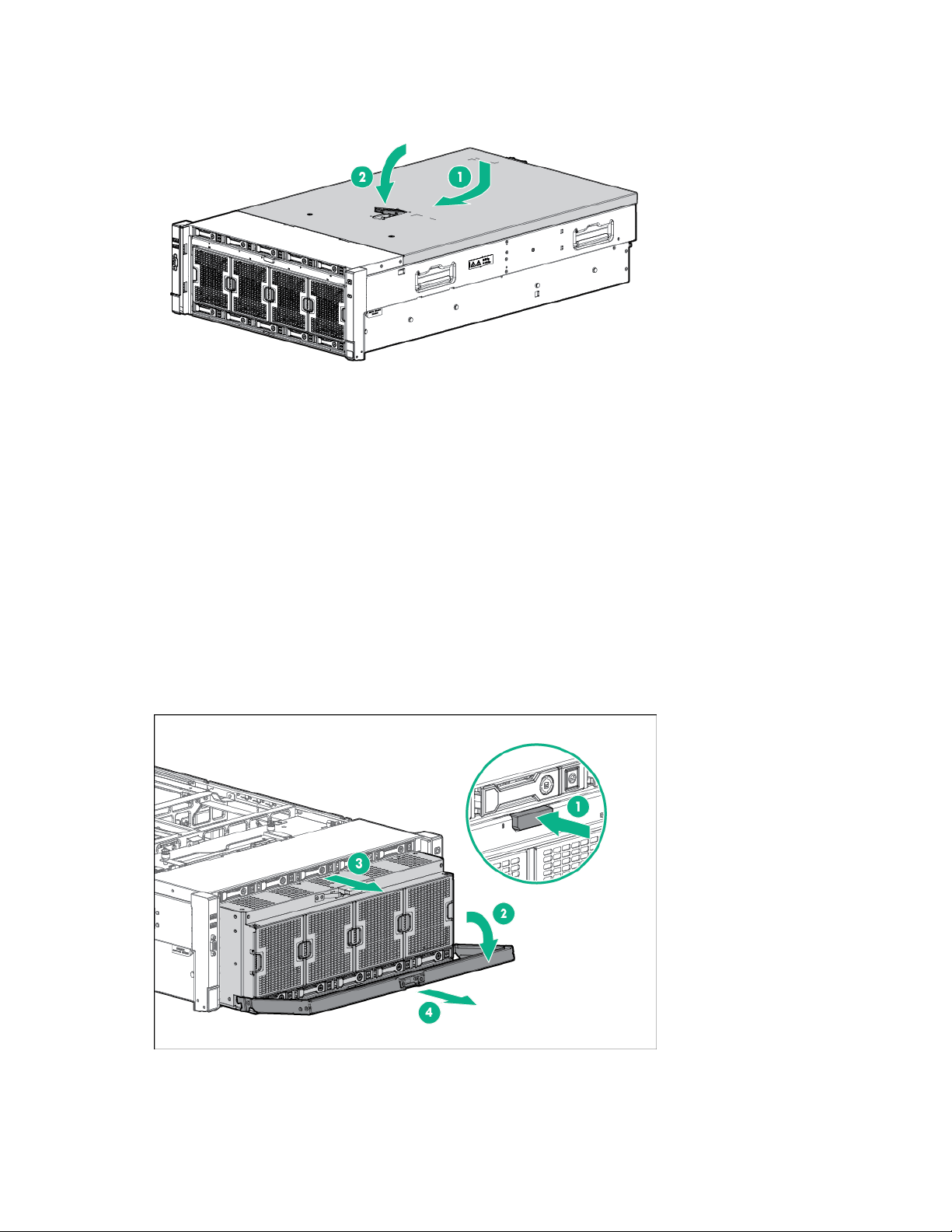
Removing the 4U rack bezel ....................................................................................................................... 73
Installing the 4U rack bezel ......................................................................................................................... 74
Redundant hot-plug power supply option ............................................................................................................... 74
DC power supply option ......................................................................................................................................... 75
Expansion board option .......................................................................................................................................... 81
Installing an expansion board ...................................................................................................................... 83
FBWC module and capacitor pack option .............................................................................................................. 85
Trusted Platform Module option ............................................................................................................................. 87
Retaining the recovery key/password.......................................................................................................... 87
Installing the Trusted Platform Module board .............................................................................................. 88
Enabling the Trusted Platform Module ........................................................................................................ 89
Cabling .................................................................................................................................................... 90
SPI board cabling ................................................................................................................................................... 90
Front video/USB cabling ......................................................................................................................................... 91
Systems Insight Display cabling ............................................................................................................................. 91
Power supply data cabling ..................................................................................................................................... 92
Standby power cabling ........................................................................................................................................... 92
Software and configuration utilities ......................................................................................................... 93
Product QuickSpecs ............................................................................................................................................... 93
Server mode ........................................................................................................................................................... 93
HPE iLO ................................................................................................................................................................. 93
Active Health System .................................................................................................................................. 93
iLO RESTful API support ............................................................................................................................. 94
Integrated Management Log ....................................................................................................................... 95
HPE Insight Remote Support ...................................................................................................................... 95
HPE ProLiant Pre-boot Health Summary .................................................................................................... 96
HPE Insight Diagnostics ......................................................................................................................................... 96
HPE Insight Diagnostics survey functionality .............................................................................................. 96
Intelligent Provisioning ........................................................................................................................................... 97
Erase Utility ................................................................................................................................................. 97
Scripting Toolkit for Windows and Linux ................................................................................................................ 97
Service Pack for ProLiant ....................................................................................................................................... 98
HP Smart Update Manager ......................................................................................................................... 98
HPE UEFI System Utilities ..................................................................................................................................... 98
Using UEFI System Utilities ......................................................................................................................... 99
Flexible boot control .................................................................................................................................... 99
Contents 4

Restoring and customizing configuration settings ....................................................................................... 99
Secure Boot configuration ......................................................................................................................... 100
Embedded UEFI shell................................................................................................................................ 100
Embedded Diagnostics option ................................................................................................................... 100
iLO RESTful API support for UEFI ............................................................................................................ 101
Re-entering the server serial number and product ID ............................................................................... 101
Utilities and features ............................................................................................................................................. 101
HPE Smart Storage Administrator ............................................................................................................. 101
Automatic Server Recovery ....................................................................................................................... 102
USB support .............................................................................................................................................. 102
Redundant ROM support........................................................................................................................... 102
Keeping the system current .................................................................................................................................. 103
Access to Hewlett Packard Enterprise Support Materials ......................................................................... 103
Updating firmware or System ROM ........................................................................................................... 103
Drivers ....................................................................................................................................................... 105
Software and firmware............................................................................................................................... 105
Operating System Version Support ........................................................................................................... 105
Version control........................................................................................................................................... 105
Operating systems and virtualization software support for ProLiant servers ............................................. 106
HPE Technology Service Portfolio ............................................................................................................ 106
Change control and proactive notification ................................................................................................. 106
Troubleshooting .................................................................................................................................... 107
Troubleshooting resources ................................................................................................................................... 107
Battery replacement .............................................................................................................................. 108
Warranty and regulatory information ..................................................................................................... 110
Warranty information ............................................................................................................................................ 110
Regulatory information ......................................................................................................................................... 110
Safety and regulatory compliance ............................................................................................................. 110
Belarus Kazakhstan Russia marking ......................................................................................................... 110
Turkey RoHS material content declaration ................................................................................................ 111
Ukraine RoHS material content declaration .............................................................................................. 111
Specifications ........................................................................................................................................ 112
Environmental specifications ................................................................................................................................ 112
Mechanical specifications ..................................................................................................................................... 112
Power supply specifications ................................................................................................................................. 112
HPE 1200 W Common Slot Platinum Plus Hot-Plug Power Supply (94% efficiency) ............................... 112
HPE 1500 W Common Slot -48 VDC Hot-plug Power Supply .................................................................. 113
HPE 1500 W Common Slot Platinum Plus Hot-Plug Power Supply (94% efficiency) ............................... 114
Support and other resources ................................................................................................................ 115
Accessing Hewlett Packard Enterprise Support ................................................................................................... 115
Information to collect ................................................................................................................................. 115
Accessing updates ............................................................................................................................................... 115
Websites ............................................................................................................................................................... 115
Customer Self Repair ........................................................................................................................................... 116
Remote support .................................................................................................................................................... 123
Documentation feedback ...................................................................................................................................... 124
Acronyms and abbreviations................................................................................................................. 125
Index ..................................................................................................................................................... 128
Contents 5
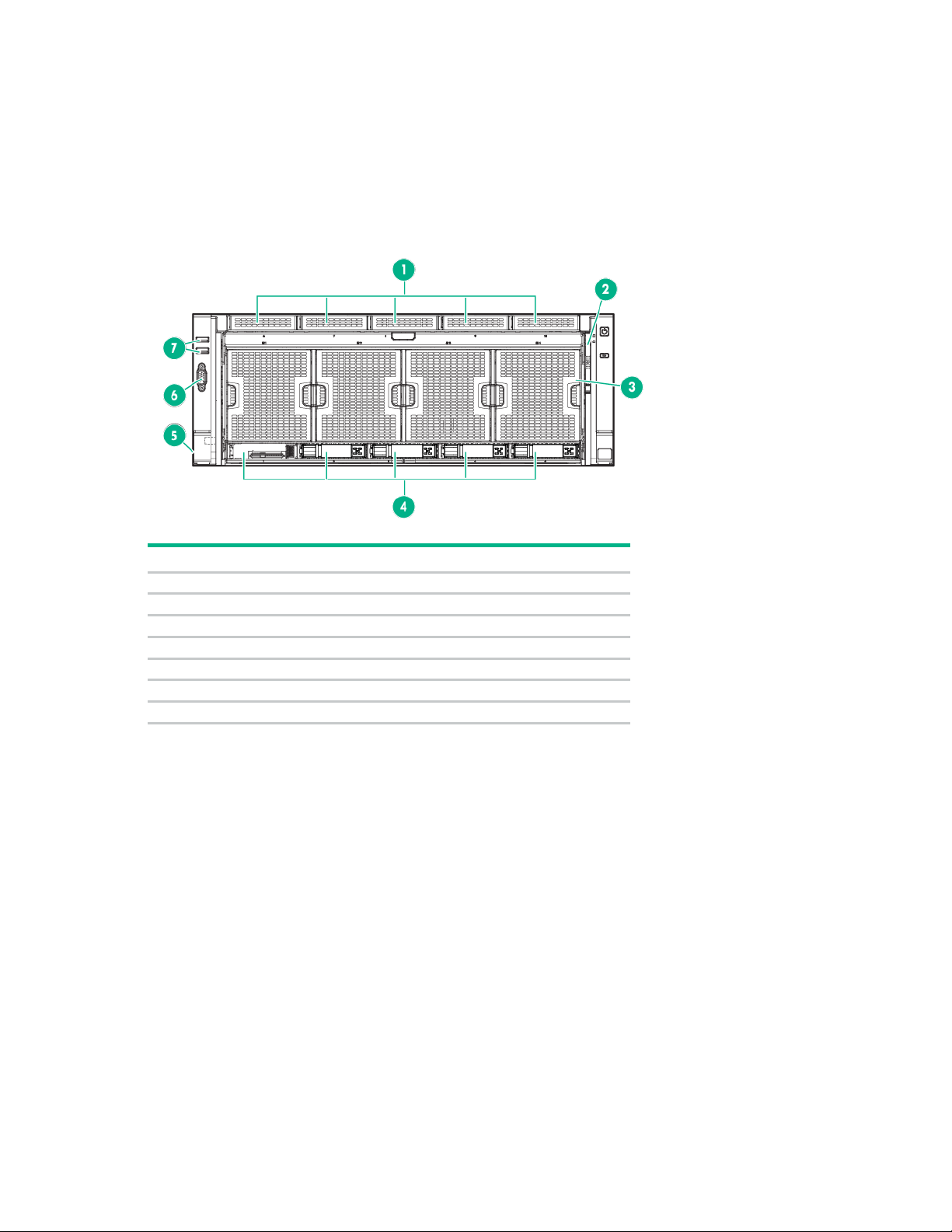
Component identification
Item
Description
1
Drive bays 6 to 10*
2
Systems Insight Display
3
Fans 1 to 4
4
Drive bays 1 to 5
5
Discovery services connectors
6
Video connector
7
USB connectors (2)
Front panel components
* Drives installed in these bays require the optional drive backplane and cables.
Component identification 6
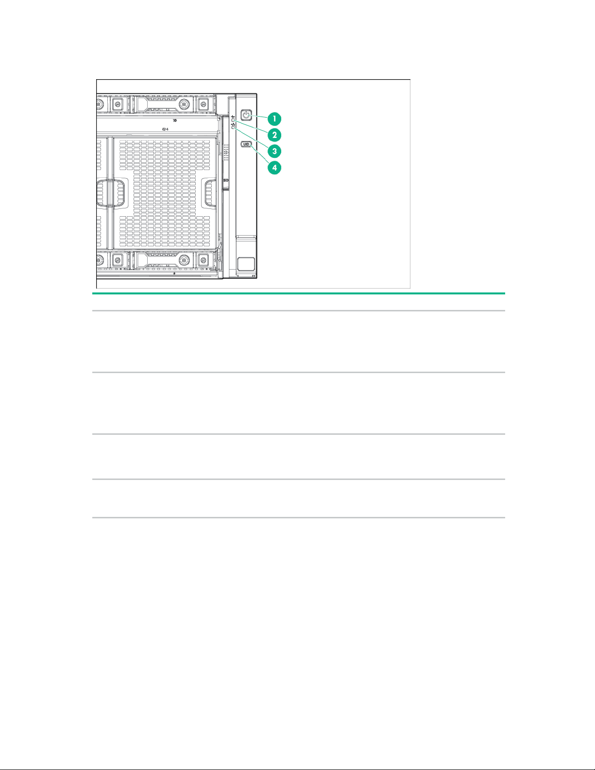
Front panel LEDs and buttons
Item
Description
Status
Power On/Standby button and
•
•
•
•
Health LED
•
•
•
•
Aggregate NIC LED
•
•
•
UID button/link
•
•
1
system power LED
Solid green = System on
Flashing green (1 Hz/cycle per sec) = Performing
power on sequence
Solid amber = System in standby
Off = No power present
2
Solid green = Normal
Flashing amber = System degraded
Flashing red (1 Hz/cycle per sec) = System critical
Fast-flashing red (4 Hz/cycles per sec) = System
power fault
3
Solid green = Link to network
Flashing green = Linked with activity on the network
Off = No network connection
4
Solid blue = Activated
Flashing blue (1 Hz/cycle per sec) = Remote
management or firmware upgrade in progress
Component identification 7
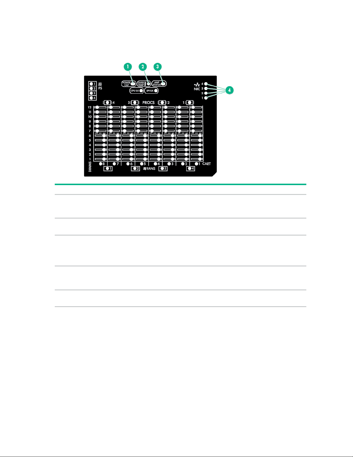
Systems Insight Display
Power cap
•
•
•
Overtemperature
•
•
AMP status
•
•
•
•
NIC activity/link
•
•
•
All other LEDs
•
•
The Systems Insight Display LEDs represent the server and component layout.
Item LED Description
1
Green = System on or requesting power on
Flashing amber = Power on denied
Off = Standby
2
Off = Normal
Amber = Failed or missing component
3
Off = No protection
Green = Protection enabled
Amber = Memory failure occurred
Amber (flashing) = Memory configuration error
4
Green = Linked to network
Green (flashing) = Linked with activity on the network
Off = No network connection
Off = Normal
Amber = Failed or missing component
Component identification 8
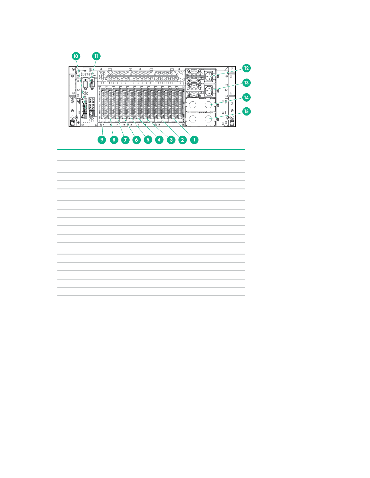
Rear panel components
Item
Description
Expansion board slot 1
2
Expansion board slot 2
3
Expansion board slot 3
Expansion board slot 4
5
Expansion board slot 5
6
Expansion board slot 6
7
Expansion board slot 7
8
Expansion board slot 8
9
Expansion board slot 9
FlexibleLOM slot
11
SPI board
12
Power supply 1
13
Power supply 2
14
Power supply bay 3
15
Power supply bay 4
1
4
10
Component identification 9
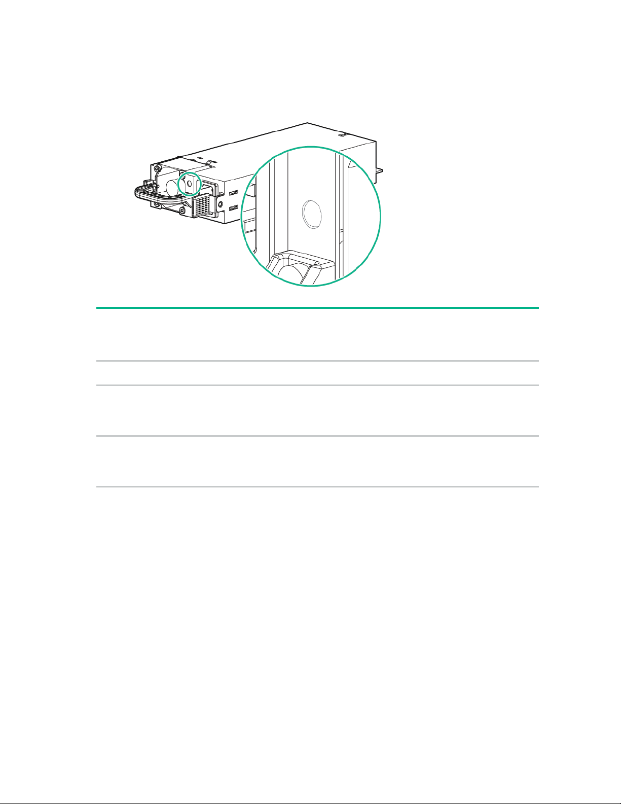
Power supply LED
panel)
Off
Off
No AC power to power
On
Green
•
•
Off
•
•
Fail LED-amber
(Located on the SID)
Off
Off
Power LED-green
(Located on the
power supply)
Front external health
LED
(Located on the front
Status
supply units
AC present/Standby
outputs on
Power supply DC outputs
on and OK
On
Amber (flashing) –
redundant
Red (flashing) –
non-redundant
Power supply failure
(includes over voltage and
over temperature)
Component identification 10
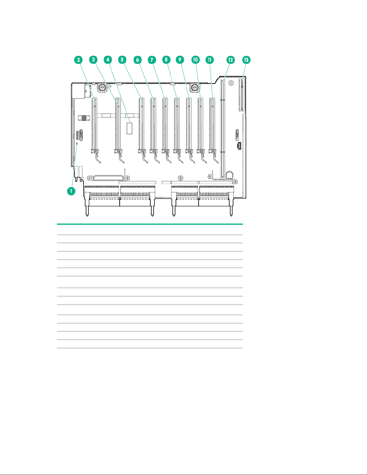
I/O board components
Item
Description
1
NMI jumper
2
Slot 1 PCIe3 x16 (16, 8, 4, 2, 1 electrical)
3
Slot 2 PCIe3 x16 (16, 8, 4, 2, 1 electrical)
4
System maintenance switch
5
Slot 3 PCIe3 x16 (16, 8, 4, 2, 1 electrical)
Slot 4 PCIe3 x16 (8, 4, 2, 1 electrical)
7
Slot 5 PCIe3 x16 (8, 4, 2, 1 electrical)
8
Slot 6 PCIe3 x16 (16, 8, 4, 2, 1 electrical)
Slot 7 PCIe3 x16 (8, 4, 2, 1 electrical)
10
Slot 8 PCIe3 x16 (8, 4, 2, 1 electrical)
11
Slot 9 PCIe3 x16 (16, 8, 4, 2, 1 electrical)
12
SPI board connector
13
FlexibleLOM connector
6
9
Component identification 11
•
•
•
•
•
•
•
•
•
•
Reserved
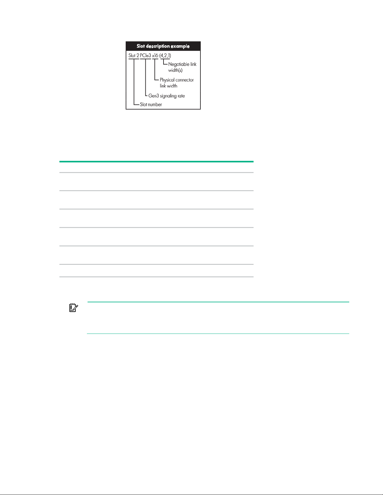
recommends setting system maintenance switch 7 to the same BIOS boot mode the server is
System maintenance switch
The system maintenance switch (SW1) is a twelve-position switch that is used for system configuration.
The default position for all twelve positions is Off.
Switch Settings
1
2
5
6
7*
3, 4, 8, 9, 10, 11, 12
* The default position for switch 7 is set in the factory shipping configuration. This switch setting determines the BIOS
mode the system defaults to when configuration memory is cleared to factory defaults. The User defined defaults
setting in UEFI System Utilities supersedes this switch.
IMPORTANT: To avoid a mismatch between boot modes, Hewlett Packard Enterprise
Off = iLO security enabled
On = iLO security disabled
Off = Normal operation
On = The BIOS configuration is locked.
Off = Normal operation
On = Password disabled
Off = Normal operation
On = Clear CMOS and RAM
Off = Set factory default boot mode to UEFI.
On = Set factory default boot mode to Legacy.
deployed in. Otherwise, the storage controller may not recognize the OS installed on the
storage media.
NMI jumper
The NMI jumper allows administrators to perform a memory dump before performing a hard reset. Crash
dump analysis is an essential part of eliminating reliability problems, such as hangs or crashes in OSs,
device drivers, and applications. Many crashes can freeze a system, requiring you to do a hard reset.
Resetting the system erases any information that would support root cause analysis.
Systems running Microsoft® Windows® experience a blue-screen trap when the OS crashes. When this
happens, Microsoft® recommends that system administrators perform an NMI event by temporarily
shorting the NMI header with a jumper. The NMI event enables a hung system to become responsive
again.
Component identification 12
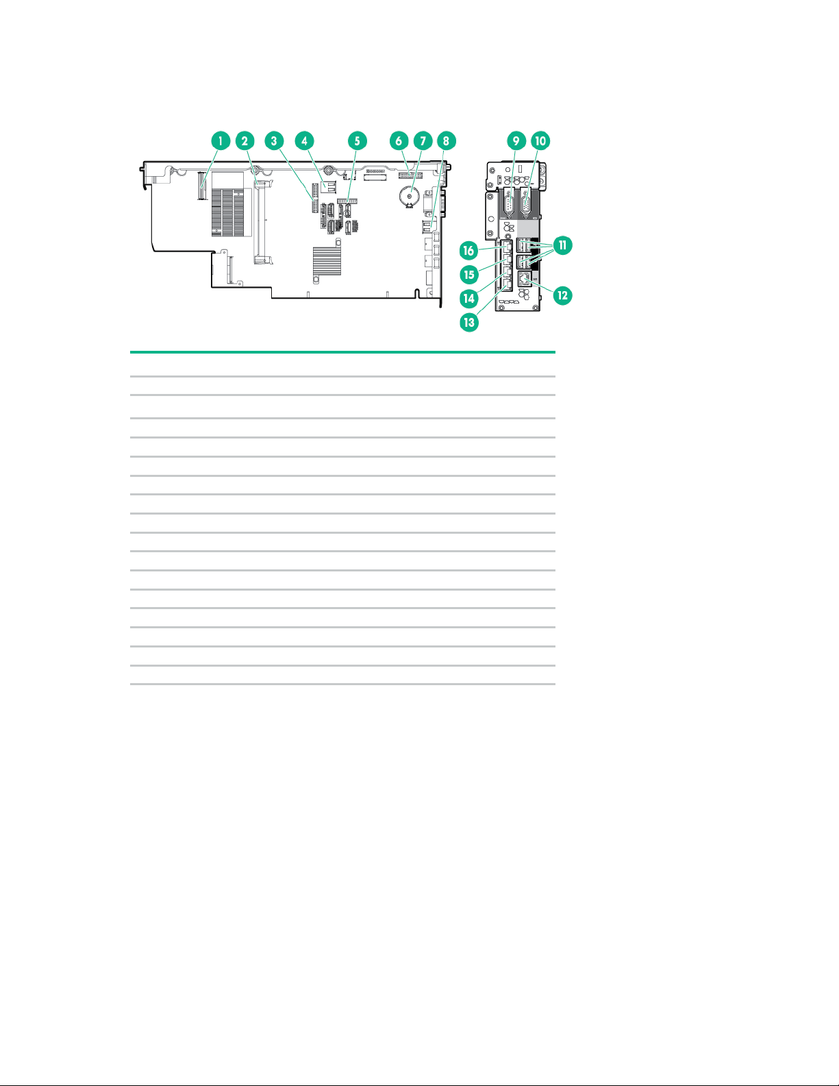
SPI board components
Item
Description
1
Top SAS backplane connector
SAS cache module connector
3
Systems Insight Display Power/UID connector
4
Internal USB connector
5
TPM connector
6
Front video/USB connector
7
Battery
8
Internal USB connector
9
Serial connector
10
Video connector
11
USB connectors (4)
12
iLO connector
13
FlexibleLOM port 1*
14
FlexibleLOM port 2*
15
FlexibleLOM port 3*
16
FlexibleLOM port 4*
2
*Port configuration is dependent on the installed FlexibleLOM and might differ from what is shown in the illustration.
Component identification 13
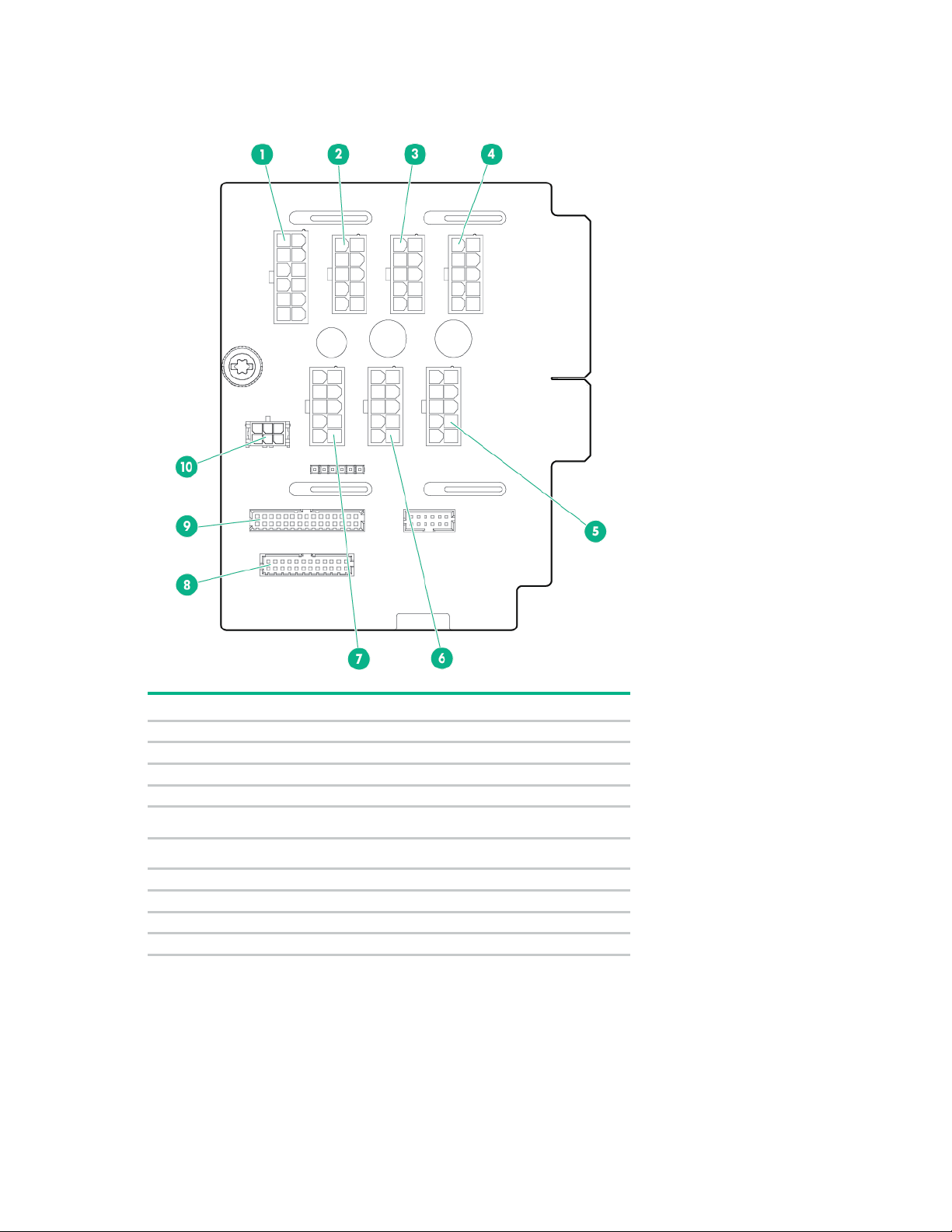
Power daughter board components
Item
Description
1
Upper SAS backplane power connector
2
I/O board auxiliary power connector
3
I/O board auxiliary power connector
4
I/O board auxiliary power connector
I/O board auxiliary power connector
I/O board auxiliary power connector
7
I/O board auxiliary power connector
8
Power backplane data connector
9
Power backplane data connector
10
I/O board power connector
5
6
Component identification 14
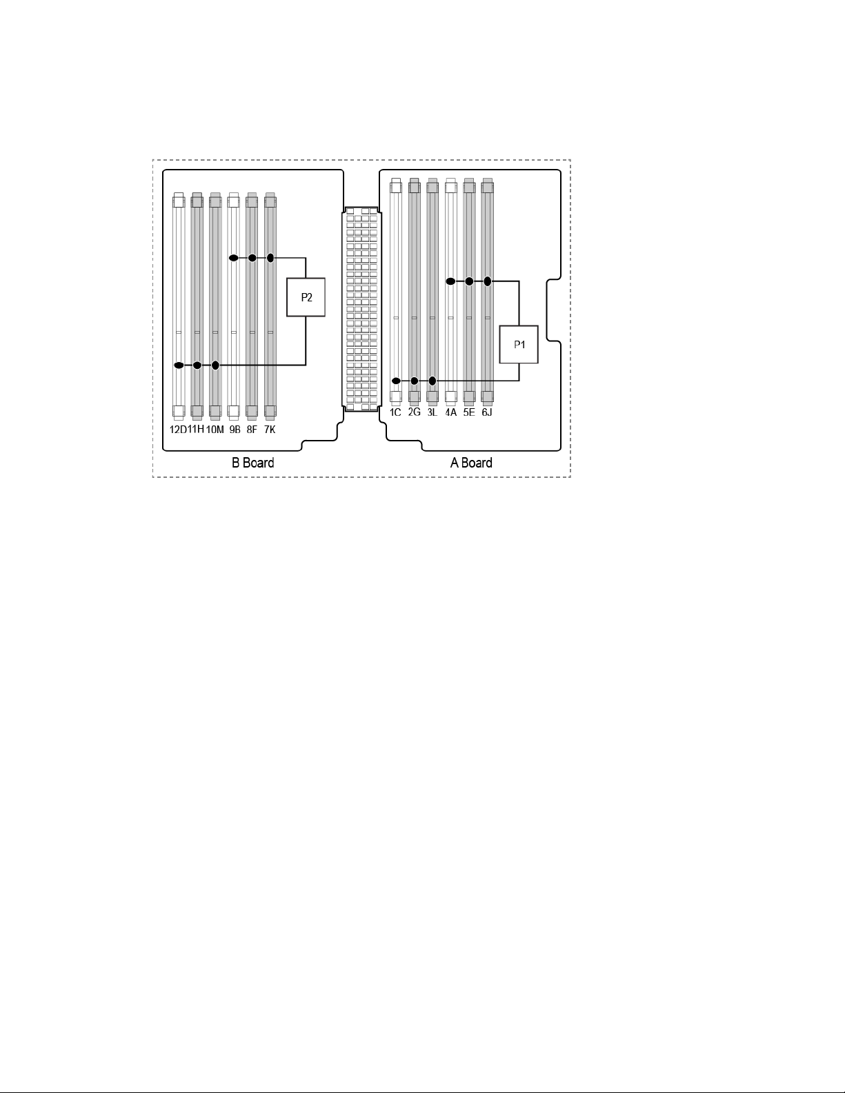
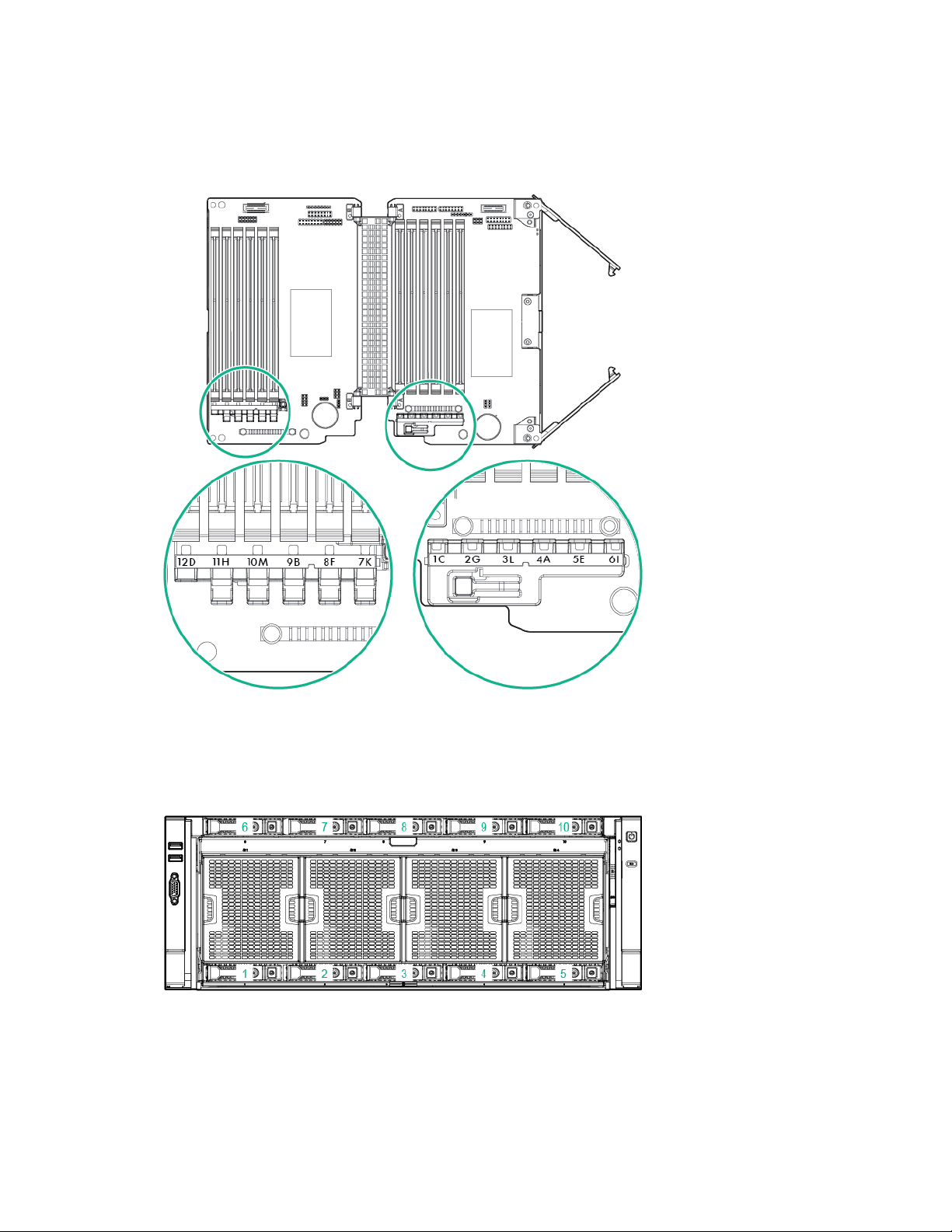
DIMM slot locations
Each memory cartridge contains 12 DIMM slots. Install DIMMs in pairs in alphabetical order.
For installation guidelines, see "Memory options (on page 48)."
Component identification 15
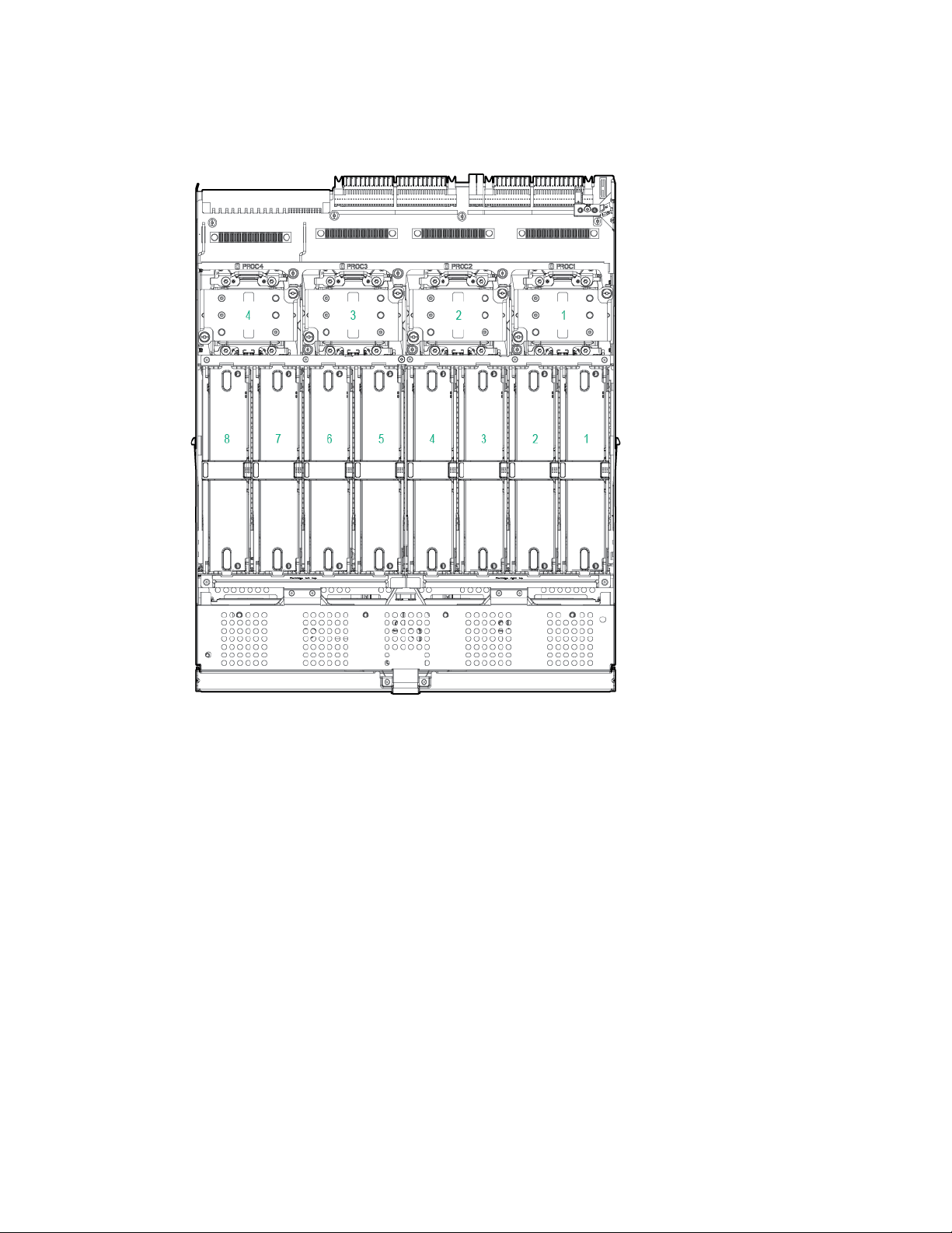
Processors and memory cartridges
The processor memory drawer contains 4 processor sockets and 8 memory cartridges.
For DIMM numbering, see "DIMM slot locations (on page 15)."
For installation guidelines, see "Memory options (on page 48)."
Component identification 16
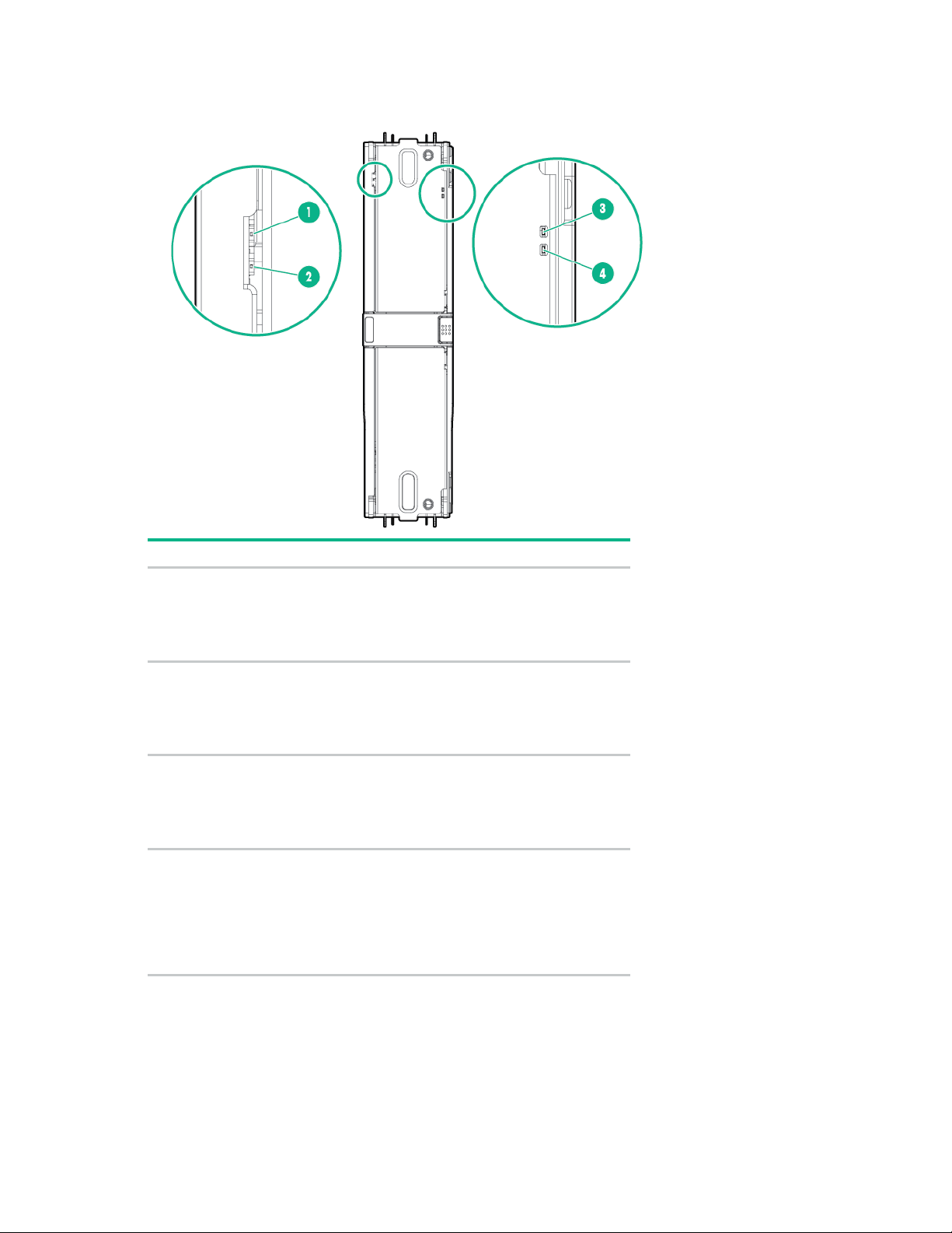
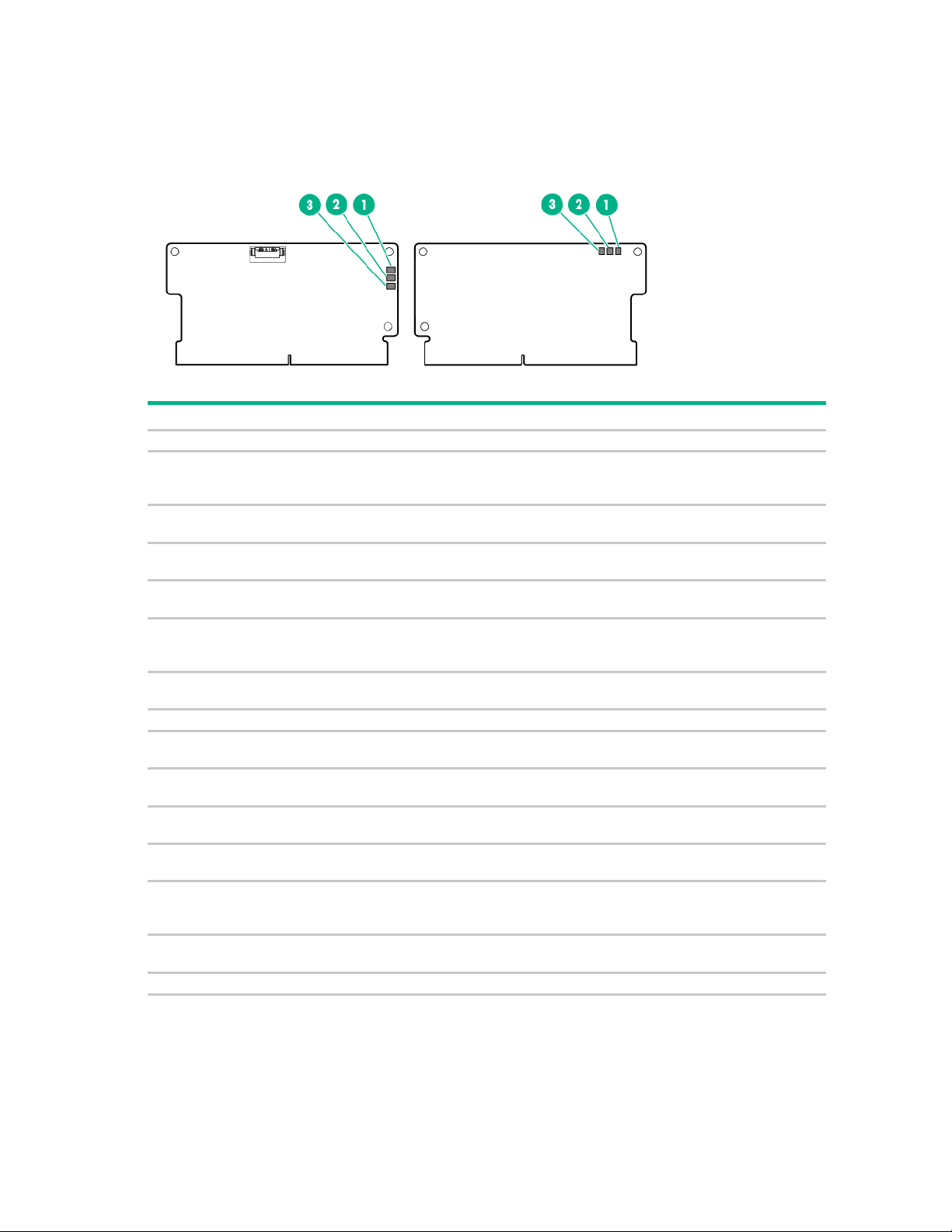
DIMM fault LEDs
Item
Description
Status
Power fault LED (board
•
•
General board fault LED
•
•
General board fault LED
•
•
Power fault LED (board
•
•
1
B)
2
(board B)
Off = The DIMMs are operating
normally.
Solid amber = One or more DIMMs
in the cartridge is experiencing a
power fault condition.
Off = The DIMMs are operating
normally.
Solid amber = One or more DIMMs
in the cartridge is experiencing a
general fault condition.
3
(board A)
Off = The DIMMs are operating
normally.
Solid amber = One or more DIMMs
in the cartridge is experiencing a
general fault condition.
4
A)
Off = The DIMMs are operating
normally.
Solid amber = One or more DIMMs
in the cartridge is experiencing a
power fault condition.
To determine which DIMMs are experiencing a fault condition, see "DIMM fault identification button (on
page 18)."
Component identification 17
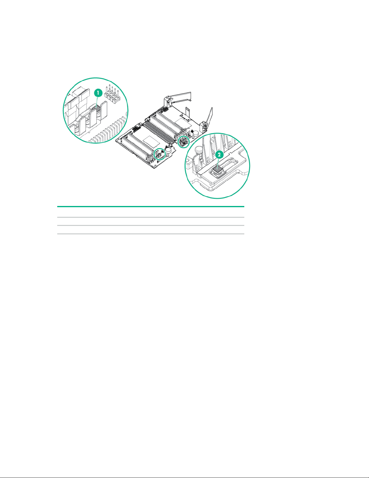
DIMM fault identification button
1
Board B DIMM fault identification button
2
Board A DIMM fault identification button
When the DIMM fault LEDs (on page 17) indicate that a DIMM is experiencing an error, press the DIMM
fault identification button to illuminate the LED below the affected DIMM ("Memory error LEDs" on page
19).
Item Description
Component identification 18
Memory error LEDs
When the DIMM fault LEDs (on page 17) indicate that a DIMM is experiencing an error, the memory error
LED below the affected DIMM illuminates red when the DIMM fault identification button (on page 18) is
pressed.
Drive bay numbering
Drives installed in bays 6 to 10 require the optional SAS backplane or Express Bay enablement option.
Component identification 19
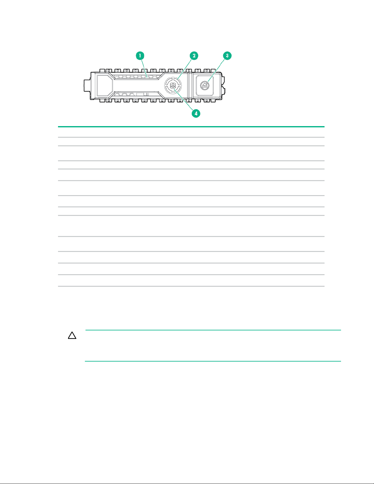
Hot-plug drive LED definitions
1
Locate
Solid blue
The drive is being identified by a host application.
Flashing blue
The drive carrier firmware is being updated or requires an
2
Activity ring
Rotating green
Drive activity
Off
No drive activity
Do not remove
Solid white
Do not remove the drive. Removing the drive causes one or
Off
Removing the drive does not cause a logical drive to fail.
4
Drive status
Solid green
The drive is a member of one or more logical drives.
Flashing green
The drive is rebuilding or performing a RAID migration, strip size
Flashing
The drive is a member of one or more logical drives and predicts
Flashing amber
The drive is not configured and predicts the drive will fail.
Solid amber
The drive has failed.
Off
The drive is not configured by a RAID controller.
button LED is flashing. The Do Not Remove button LED flashes to indicate the device is still in
Item LED Status Definition
update.
3
more of the logical drives to fail.
amber/green
migration, capacity expansion, or logical drive extension, or is
erasing.
the drive will fail.
NVMe SSD components
The NVMe SSD is a PCIe bus device. A device attached to a PCIe bus cannot be removed without
allowing the device and bus to complete and cease the signal/traffic flow.
CAUTION: Do not remove an NVMe SSD from the drive bay while the Do Not Remove
use. Removal of the NVMe SSD before the device has completed and ceased signal/traffic
flow can cause loss of data.
Component identification 20
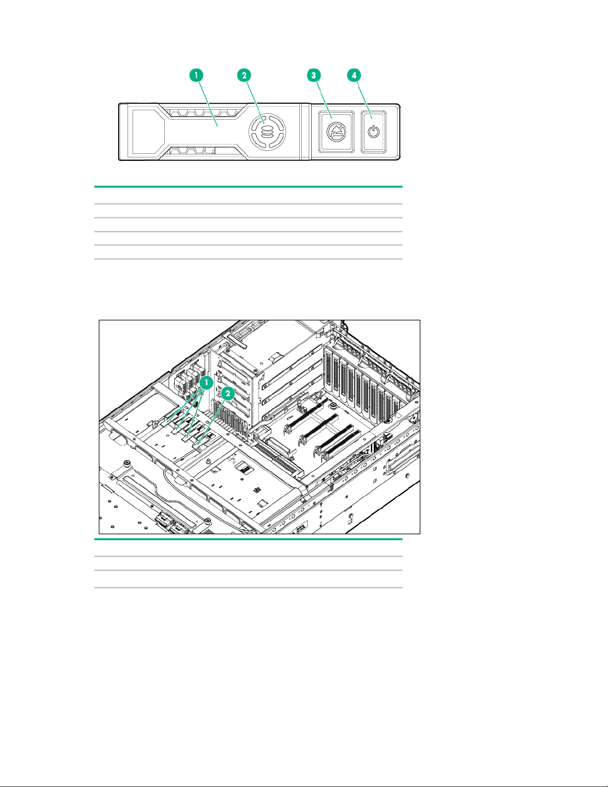
Item
Description
1
Release lever
2
Activity ring
3
Do Not Remove button
4
Power button
Item
Description
1
Slots 2 to 4—Connect to optional SAS controllers
Slot 1—Connects to the SPI board
FBWC capacitor slots
2
Component identification 21
FBWC module LEDs
1 - Amber
2 - Green
3 - Green
Interpretation
Off
Off
Off
The cache module is not powered.
Flashing once
Flashing once
The cache microcontroller is executing from within its
Flashing once
Flashing once
The cache module is powering up, and the capacitor
Off
Flashing once
The cache module is idle, and the capacitor pack is
Off
On
The cache module is idle, and the capacitor pack is
On
On
The cache module is idle, the capacitor pack is
Flashing once
Off
A backup of the DDR content on the cache module is
Off
On
Off
The current backup is complete with no errors.
per second
Flashing once
Off
The current backup failed, and data has been lost.
per second
Flashing once
On
A power error occurred during the previous or current
per second
On
Off
An overtemperature condition exists.
per second
Flashing twice
Off
The capacitor pack is not attached.
Flashing twice
On
The capacitor has been charging for 10 minutes, but
On
Off
The current backup is complete, but power
On
On
On
The cache module microcontroller has failed.
The FBWC module has three single-color LEDs (one amber and two green). The LEDs are duplicated on
the reverse side of the cache module to facilitate status viewing.
Off
Off
Off
Off
Off
Off
Flashing once
Flashing once
Flashing once
every 2 seconds
per second
per second
per second
per second
every 2 seconds
per second
per second
boot loader and receiving new flash code from the host
controller.
pack is charging.
charging.
charged.
charged, and the cache contains data that has not yet
been written to the drives.
in progress.
boot. Data may be corrupt.
Flashing twice
Flashing twice
per second
On
per second
per second
has not reached sufficient charge to perform a full
backup.
fluctuations occurred during the backup.
Component identification 22
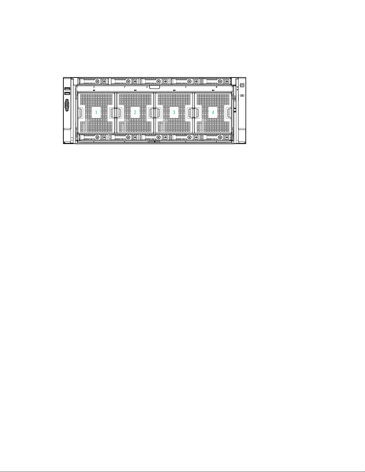
Fans
Fan locations
Fan guidelines
The server has 4 fan modules with 2 rotors in each module. The fan modules operate in a 7+1
configuration.
Observe the following guidelines:
• If one rotor fails, the system runs with the fans in a degraded condition.
• If a second rotor fails, either in the same fan module or a different one, the system performs an OS
type shutdown if the health OS agents are loaded. The chance of two rotors in the same module
failing is low.
• If a fan module is missing, a message appears indicating that cooling is not adequate. Then, the
system starts to shut down.
• If you remove a hot-plug fan module, you have approximately 60 seconds to replace the module.
Otherwise, the system starts to shut down.
Component identification 23
Operations
To reduce the risk of personal injury, electric shock, or damage to the equipment,
To reduce the risk of personal injury or equipment damage, be sure that the rack
This symbol indicates that the component exceeds the recommended weight for one
observe local occupational health and safety requirements and guidelines for manual
Powering up the server
To power up the server, press the Power On/Standby button.
Power down the server
WARNING:
remove the power cord to remove power from the server. The front panel Power On/Standby
button does not completely shut off system power. Portions of the power supply and some
1. Back up the server data.
2. Shut down the operating system. For more information, see the operating system documentation.
3. Press the Power On/Standby button to place the server in Standby mode. When the server activates
4. Disconnect the power cords.
internal circuitry remain active until AC power is removed.
IMPORTANT: If installing a hot-plug device, it is not necessary to power down the server.
NOTE: If the operating system automatically places the server in Standby mode, omit the
next step.
Standby power mode, the system power LED changes to amber.
IMPORTANT: Pressing the UID button illuminates the blue UID LEDs on the front and rear
panels. In a rack environment, this feature facilitates locating a server when moving between
the front and rear of the rack.
The system is now without power.
Remove the server from the rack
WARNING:
is adequately stabilized before extending a component from the rack.
WARNING: To reduce the risk of personal injury, be careful when pressing the server
rail-release latches and sliding the server into the rack. The sliding rails could pinch your
32.18-52.87 kg
70.94-116.56 lb
To remove the server from the rack:
1. Pull down the quick-release levers on each side of the server to release the server from the rack. If
fingers.
individual to handle safely.
WARNING: To reduce the risk of personal injury or damage to the equipment,
material handling.
necessary, loosen the rack screws.
Operations 24

To reduce the risk of personal injury or equipment damage, be sure that the rack
2.
Extend the server on the rack rails until the server rail-release latches engage.
3. Remove the server from the rack.
Extend the server from the rack
WARNING:
is adequately stabilized before extending a component from the rack.
WARNING: To reduce the risk of personal injury, be careful when pressing the server
rail-release latches and sliding the server into the rack. The sliding rails could pinch your
To extend the server from the rack:
1. Pull down the quick-release levers on each side of the server to release the server from the rack. If
2. Extend the server on the rack rails until the server rail-release latches engage.
fingers.
necessary, loosen the rack screws.
Operations 25

3.
removed. Operating the server in this manner results in improper airflow and improper cooling
After performing the installation or maintenance procedure, slide the server into the rack by pressing
the server rail-release latches.
Remove the access panel
WARNING: To reduce the risk of personal injury from hot surfaces, allow the drives and the
internal system components to cool before touching them.
CAUTION: Do not operate the server for long periods with the access panel open or
To remove the component:
1. Power down the server (on page 24).
2. Extend the server from the rack (on page 25).
3. Remove the access panel. If the locking latch is locked, use a T-15 Torx screwdriver to unlock the
that can lead to thermal damage.
latch.
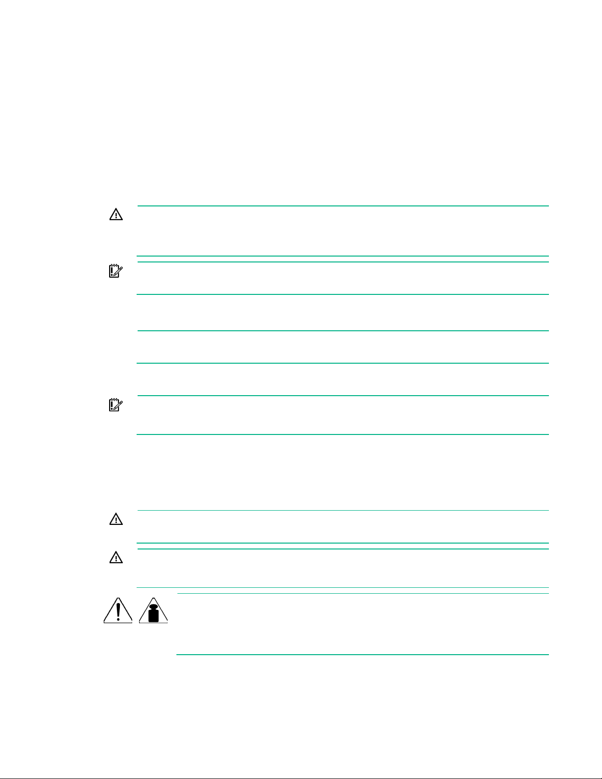
Install the access panel
1. Ensure that the access panel latch is in the open position.
Operations 26
2.
Align the hole in the access panel latch with the guide pin on the chassis.
3. Close the access panel latch. The access panel slides to a closed position.
4. Use a T-15 Torx screwdriver to tighten the access panel latch screw.
Remove the SPI board
To remove the component:
1. Power down the server (on page 24).
2. Remove all power:
a. Disconnect each power cord from the power source.
b. Disconnect each power cord from the server.
3. Extend the server from the rack (on page 25).
4. Remove the access panel (on page 26).
5. Remove the processor memory drawer shipping screws, if installed. Retain the screws for future use
("Processor memory drawer shipping screw locations" on page 30).
6. Extend the processor memory drawer approximately 2.54 to 5.1 cm (1 to 2 inches).
Operations 27
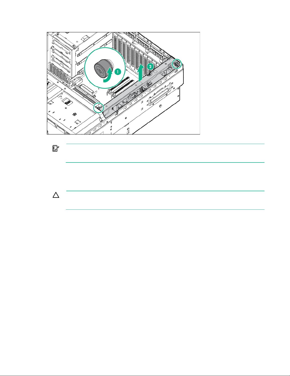
7.
Loosen the thumbscrews on the SPI board, and then lift the SPI board to access the cables.
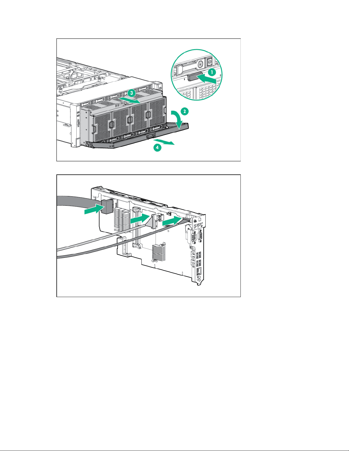
8. Disconnect all cables from the SPI board.
IMPORTANT: If replacing the SPI board or clearing NVRAM, you must re-enter the server
serial number through the Advanced System ROM options in UEFI System Utilities
9. Remove the SPI board from the server.
("Re-entering the server serial number and product ID" on page 101).
Install the SPI board
CAUTION: To prevent damage to electrical components, take the appropriate anti-static
precautions before beginning any system installation. Improper grounding can cause
To install the component:
1. Remove all power:
2. Do one of the following:
3. Remove the access panel (on page 26).
4. Remove the processor memory drawer shipping screws, if installed. Retain the screws for future use
electrostatic discharge.
a. Disconnect each power cord from the power source.
b. Disconnect each power cord from the server.
o Extend the server from the rack (on page 25).
o Remove the server from the rack (on page 24).
("Processor memory drawer shipping screw locations" on page 30).
Operations 28
5.
Extend the processor memory drawer approximately 2.54 to 5.1 cm (1 to 2 inches).
6. Connect the cables to the SPI board.
Operations 29
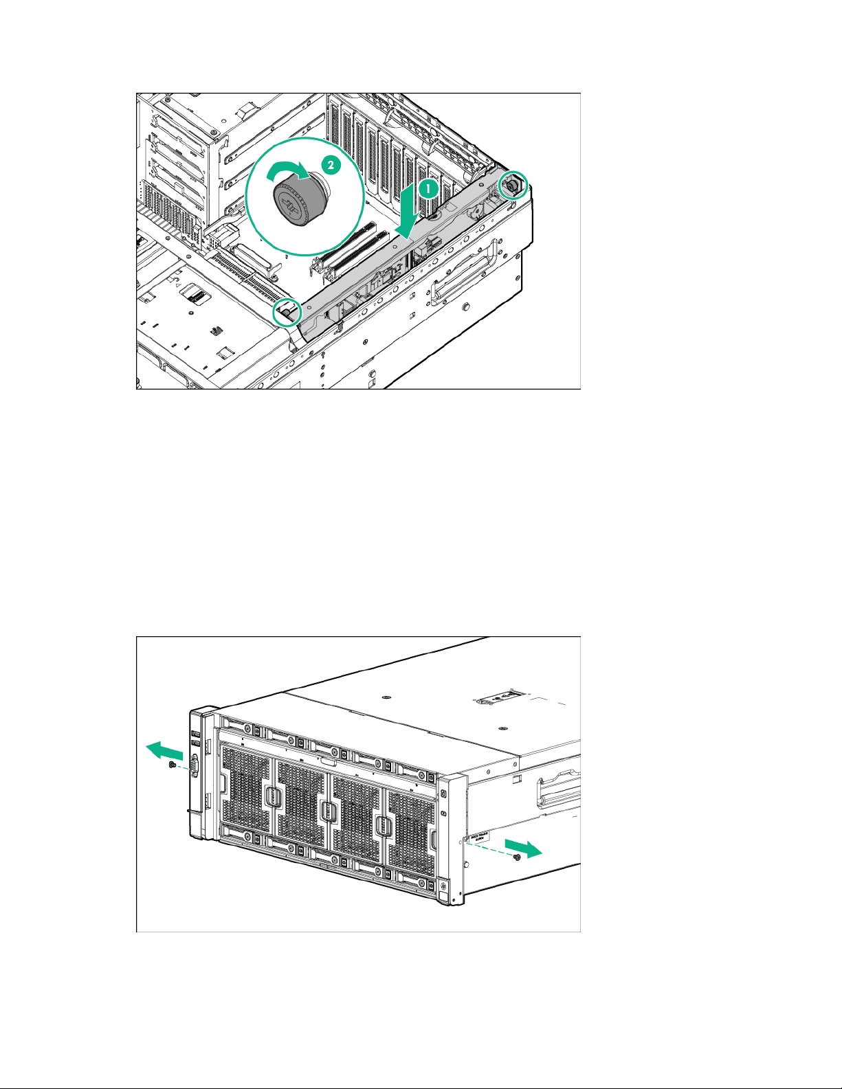
7.
Install the SPI board and tighten the thumbscrews.
8. Install the processor memory drawer ("Remove the processor memory drawer cover" on page 32, on
page 31).
9. Install the access panel (on page 26).
10. Install the server into the rack ("Installing the server into the rack" on page 38).
11. Connect each power cord to the server.
12. Connect each power cord to the power source.
13. Power up the server ("Powering up the server" on page 24).
Processor memory drawer shipping screw locations
Two orange shipping screws secure the processor memory drawer in place during shipping. You must
remove the screws to access the processor memory drawer. Retain the screws for future use.
Operations 30
 Loading...