

HP ProLiant DL560 G8 User Manual

HP ProLiant DL560 Gen8 Server
User Guide
Abstract
This document is for the person who installs, administers, and troubleshoots servers and storage systems. HP assumes you are qualified in the
servicing of computer equipment and trained in recognizing hazards in products with hazardous energy levels.
Part Number: 696744-003
February 2014
Edition: 3

© Copyright 2012, 2014 Hewlett-Packard Development Company, L.P.
The information contained herein is subject to change without notice. The only warranties for HP products and services are set forth in the express
warranty statements accompanying such products and services. Nothing herein should be construed as constituting an additional warranty. HP shall
not be liable for technical or editorial errors or omissions contained herein.
Microsoft® and Windows® are U.S. registered trademarks of Microsoft Corporation.

Contents
Component identification ............................................................................................................... 6
Front panel components ................................................................................................................................ 6
Front panel LEDs and buttons ......................................................................................................................... 6
Systems Insight Display LEDs ......................................................................................................................... 7
Systems Insight Display LED combinations ....................................................................................................... 8
Rear panel components ................................................................................................................................ 9
Rear panel LEDs and buttons ....................................................................................................................... 10
Non-hot-plug PCIe riser board slot definitions ................................................................................................ 10
System board components .......................................................................................................................... 11
System maintenance switch ............................................................................................................... 12
NMI functionality ............................................................................................................................. 13
DIMM slot locations .......................................................................................................................... 14
Hot-plug drive bay numbering ..................................................................................................................... 14
Hot-plug drive LED definitions ...................................................................................................................... 14
PCIe riser cage LED .................................................................................................................................... 15
FBWC module LEDs (P222, P420, P421) ..................................................................................................... 16
Hot-plug fans ............................................................................................................................................. 16
Operations................................................................................................................................. 18
Power up the server .................................................................................................................................... 18
Power down the server ............................................................................................................................... 18
Extend the server from the rack .................................................................................................................... 18
Access the Systems Insight Display ............................................................................................................... 19
Remove the access panel ............................................................................................................................ 20
Install the access panel ............................................................................................................................... 20
Access the product rear panel ..................................................................................................................... 21
Opening the cable management arm ................................................................................................. 21
Remove the primary PCIe riser cage ............................................................................................................. 21
Install the primary PCIe riser cage ................................................................................................................ 22
Remove the air baffle .................................................................................................................................. 23
Install the air baffle ..................................................................................................................................... 24
Setup ......................................................................................................................................... 26
Optional installation services ....................................................................................................................... 26
Optimum environment................................................................................................................................. 26
Space and airflow requirements ........................................................................................................ 26
Temperature requirements ................................................................................................................. 27
Power requirements .......................................................................................................................... 28
Electrical grounding requirements ...................................................................................................... 28
Connecting a DC power cable to a DC power source .......................................................................... 28
Rack warnings ........................................................................................................................................... 29
Identifying the contents of the server shipping carton ...................................................................................... 30
Installing hardware options ......................................................................................................................... 30
Installing the server into the rack .................................................................................................................. 30
Installing the operating system ..................................................................................................................... 32
Powering on and selecting boot options ....................................................................................................... 32
Registering the server.................................................................................................................................. 33
Contents 3

Hardware options installation ....................................................................................................... 34
Introduction ............................................................................................................................................... 34
Processor option......................................................................................................................................... 34
Memory options ......................................................................................................................................... 38
HP SmartMemory ............................................................................................................................. 40
Memory subsystem architecture ......................................................................................................... 40
Single-, dual-, and quad-rank DIMMs ................................................................................................. 41
DIMM identification .......................................................................................................................... 41
Memory configurations ..................................................................................................................... 42
General DIMM slot population guidelines ........................................................................................... 43
Installing a DIMM ............................................................................................................................. 44
Hot-plug hard drive options ......................................................................................................................... 45
Removing a hot-plug SAS or SATA hard drive ..................................................................................... 45
Installing a hot-plug SAS or SATA hard drive ...................................................................................... 46
Controller options ....................................................................................................................................... 47
Installing the flash-backed write cache module .................................................................................... 48
Installing the flash-backed write cache capacitor pack ......................................................................... 49
Redundant hot-plug power supply option ...................................................................................................... 52
FlexibleLOM option .................................................................................................................................... 54
Expansion board options ............................................................................................................................ 55
Removing the expansion slot blanks ................................................................................................... 55
Installing a half-length expansion board ............................................................................................. 56
Installing a full-length expansion board ............................................................................................... 57
Secondary PCIe riser cage option ................................................................................................................ 58
2U rack bezel option .................................................................................................................................. 60
HP Trusted Platform Module option .............................................................................................................. 61
Installing the Trusted Platform Module board ....................................................................................... 62
Retaining the recovery key/password ................................................................................................. 63
Enabling the Trusted Platform Module ................................................................................................. 63
Cabling ..................................................................................................................................... 65
SAS drive cabling ...................................................................................................................................... 65
FBWC cabling ........................................................................................................................................... 66
150W PCIe power cable option .................................................................................................................. 66
Software and configuration utilities ............................................................................................... 68
Server mode .............................................................................................................................................. 68
HP product QuickSpecs .............................................................................................................................. 68
HP iLO Management .................................................................................................................................. 68
HP iLO ............................................................................................................................................ 68
Intelligent Provisioning ...................................................................................................................... 70
HP Insight Remote Support software ................................................................................................... 72
HP Insight Online ............................................................................................................................. 72
Scripting Toolkit for Windows and Linux ............................................................................................. 73
HP Service Pack for ProLiant ........................................................................................................................ 73
HP Smart Update Manager ............................................................................................................... 73
HP ROM-Based Setup Utility ........................................................................................................................ 74
Using RBSU ..................................................................................................................................... 74
Auto-configuration process ................................................................................................................ 74
Boot options .................................................................................................................................... 75
Configuring AMP modes ................................................................................................................... 75
Re-entering the server serial number and product ID ............................................................................. 75
Utilities and features ................................................................................................................................... 76
HP Smart Storage Administrator ......................................................................................................... 76
Contents 4

Option ROM Configuration for Arrays................................................................................................ 76
ROMPaq utility ................................................................................................................................. 77
Automatic Server Recovery ................................................................................................................ 77
USB support .................................................................................................................................... 77
Redundant ROM support ................................................................................................................... 78
Keeping the system current .......................................................................................................................... 78
Drivers ............................................................................................................................................ 78
Software and firmware ..................................................................................................................... 78
Version control ................................................................................................................................. 79
HP operating systems and virtualization software support for ProLiant servers ......................................... 79
HP Technology Service Portfolio ......................................................................................................... 79
Change control and proactive notification .......................................................................................... 80
Troubleshooting .......................................................................................................................... 81
Troubleshooting resources ........................................................................................................................... 81
Battery replacement .................................................................................................................... 82
Regulatory information ................................................................................................................ 84
Safety and regulatory compliance ................................................................................................................ 84
Turkey RoHS material content declaration ..................................................................................................... 84
Ukraine RoHS material content declaration ................................................................................................... 84
Warranty information ................................................................................................................................. 84
Electrostatic discharge ................................................................................................................. 85
Preventing electrostatic discharge ................................................................................................................ 85
Grounding methods to prevent electrostatic discharge .................................................................................... 85
Specifications ............................................................................................................................. 86
Environmental specifications ........................................................................................................................ 86
Mechanical specifications ........................................................................................................................... 86
Power supply specifications ......................................................................................................................... 86
HP 1200 W CS HE Power Supply (94%) specifications ....................................................................... 86
Support and other resources ........................................................................................................ 88
Before you contact HP ................................................................................................................................ 88
HP contact information ................................................................................................................................ 88
Customer Self Repair .................................................................................................................................. 88
Acronyms and abbreviations ........................................................................................................ 96
Documentation feedback ............................................................................................................. 99
Index ....................................................................................................................................... 100
Contents 5
Component identification
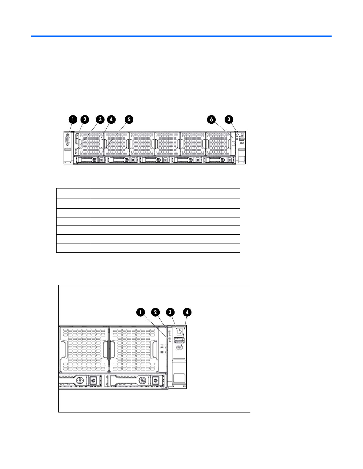
Front panel components
Item Description
1
2
3
4
5
6
Video connector
Serial pull tab
USB connector
Fan module
Hot-plug hard drive
Systems Insight Display
Front panel LEDs and buttons
Component identification 6
Item Description Status
1
2
NIC status LED Solid green = Link to network
Flashing green (1 Hz/cycle per sec) = Network active
Off = No network activity
Health LED Solid green = Normal
Flashing amber = System degraded
Flashing red (1 Hz/cycle per sec) = System critical
Fast-flashing red (4 Hz/cycles per sec) = Power fault*
3
Power On/Standby button
and system power LED
Solid green = System on
Flashing green (1 Hz/cycle per sec) = Performing power on sequence
Solid amber = System in standby
Off = No power present**
4
UID button/LED Solid blue = Activated
Flashing blue (1 Hz/cycle per sec) = Remote management or
firmware upgrade in progress
Off = Deactivated
* To identify components in a degraded or critical state, see the Systems Insight Display LEDs, check iLO/BIOS logs, and
reference the server troubleshooting guide.
** Facility power is not present, power cord is not attached, no power supplies are installed, power supply failure has
occurred, or the power button cable is disconnected.
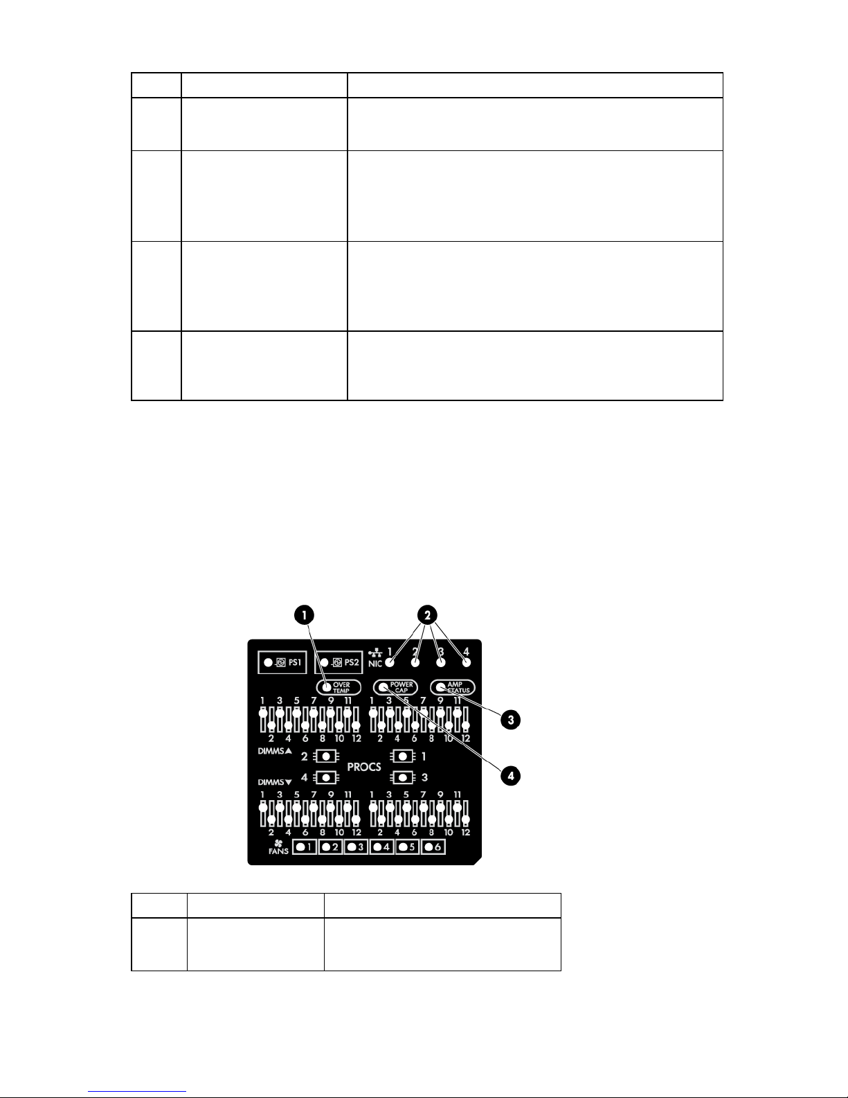
Systems Insight Display LEDs
The HP Systems Insight Display LEDs represent the system board layout. The display enables diagnosis with
the access panel installed.
Item Description Status
1
Over temp Off = Normal
Solid amber = High system temperature
detected
Component identification 7
Item Description Status
•
•
•
•
•
2
3
NIC link/activity Off = No link to network. If the power is off,
view the rear panel RJ-45 LEDs for status
("Rear panel LEDs and buttons" on page
10).
Flashing green = Network link and activity
Solid green = Network link
AMP status Off = AMP modes disabled
Solid green = AMP mode enabled
Solid amber = Failover
Flashing amber = Invalid configuration
4
—
Power cap Off = System is in standby, or no cap is set.
Solid green = Power cap applied
All other LEDs Off = Normal
Amber = Failure
For more information on the activation of
these LEDs, see "Systems Insight Display
LED combinations (on page 8)."
Systems Insight Display LED combinations
When the health LED on the front panel illuminates either amber or red, the server is experiencing a health
event. Combinations of illuminated Systems Insight Display LEDs, the system power LED, and the health LED
indicate system status.
Systems Insight Display
LED and color
Processor (amber)
Processor (amber)
DIMM (amber)
DIMM (amber)
Over temp (amber)
Over temp (amber)
Fan (amber)
Fan (amber)
Power supply (amber)
Health LED
System power
LED
Red Amber One or more of the following conditions may
Amber Green Processor in socket X is in a pre-failure
Red Green One or more DIMMs have failed.
Amber Green DIMM in slot X is in a pre-failure condition.
Amber Green The Health Driver has detected a cautionary
Red Amber The server has detected a hardware critical
Amber Green One fan has failed or has been removed.
Red Green Two or more fans have failed or been
Red Amber One or more of the following conditions may
Status
exist:
Processor in socket X has failed.
Processor X is not installed in the socket.
Processor X is unsupported.
ROM detects a failed processor during
POST.
condition.
temperature level.
temperature level.
removed.
exist:
Only one power supply is installed and
Component identification 8
•
•
•
•
•
•
7
Systems Insight Display
LED and color
Health LED
System power
LED
Status
that power supply is in standby.
Power supply fault
System board fault
Power supply (amber)
Amber Green One or more of the following conditions may
exist:
Redundant power supply is installed and
only one power supply is functional.
AC power cord is not plugged into
redundant power supply.
Redundant power supply fault
Power supply mismatch at POST or
power supply mismatch through hot-plug
addition
Power cap (off)
Power cap (green)
Power cap (green)
IMPORTANT: If more than one DIMM slot LED is illuminated, further troubleshooting is required.
— Amber Standby
— Flashing green Waiting for power
— Green Power is available.
Test each bank of DIMMs by removing all other DIMMs. Isolate the failed DIMM by replacing
each DIMM in a bank with a known working DIMM.
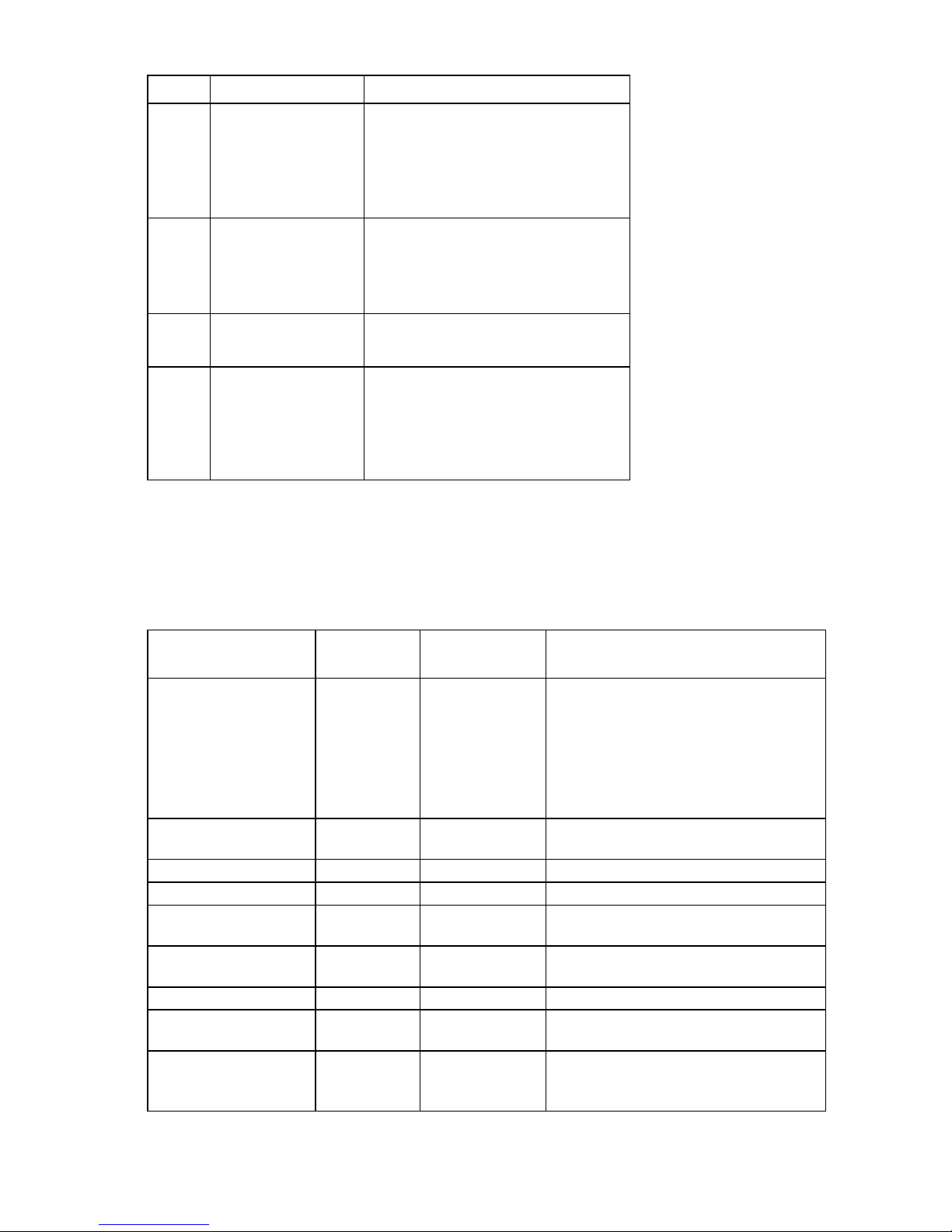
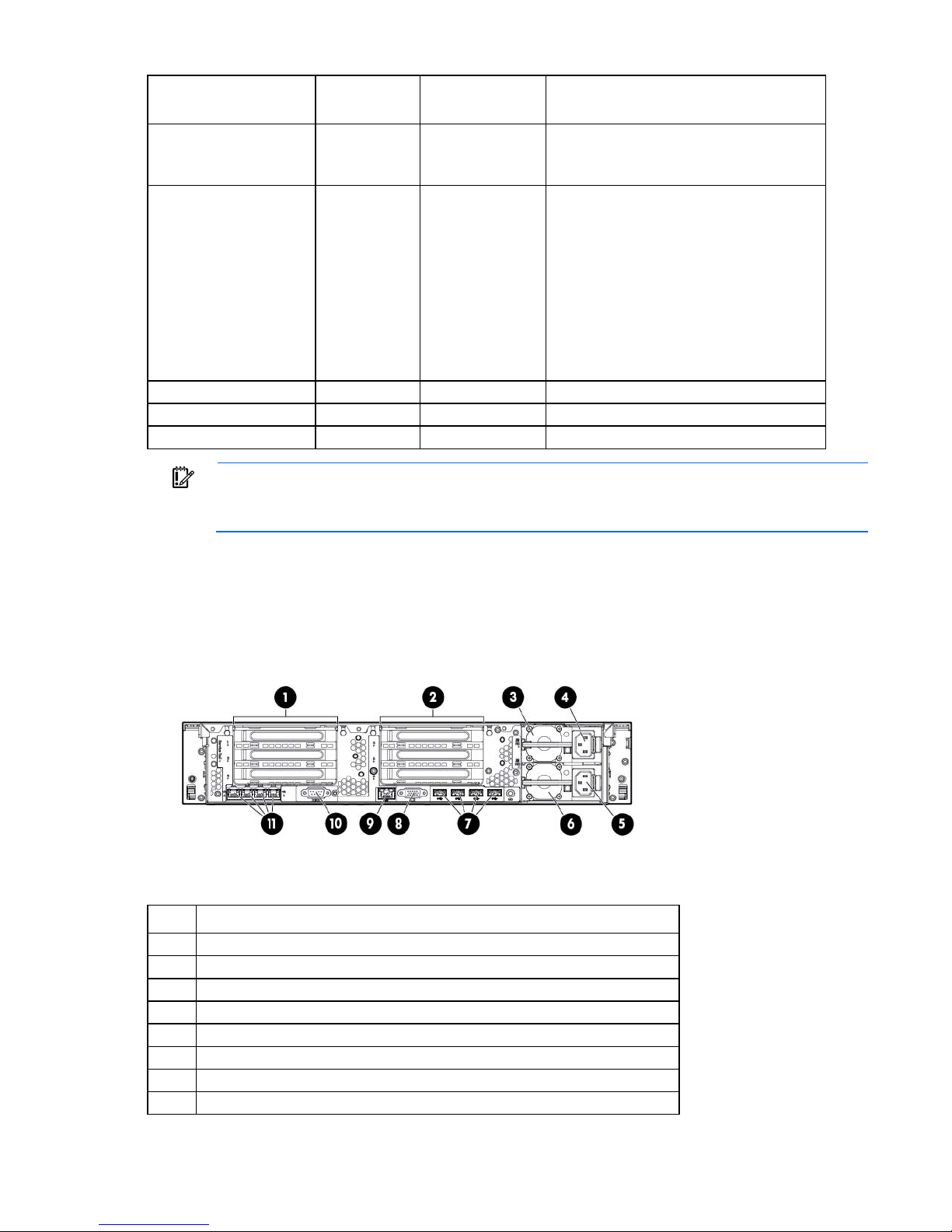
Rear panel components
Item Description
1
2
3
4
5
6
8
PCIe slots 1–3 (top to bottom)
PCIe slots 4–6 (top to bottom)
Power supply 1 (PS1)
Power supply 1 power connector
Power supply 2 power connector
Power supply 2 (PS2)
USB connectors (4)
Video connector
Component identification 9
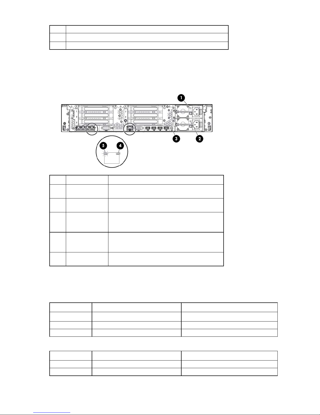
9
10
11
iLO connector
Serial connector
FlexibleLOM ports (Shown: 4x1Gb/Optional: 2x10Gb); port 1 on right side
Rear panel LEDs and buttons
Item Description Status
1
Power supply 1
LED
2
Power supply 2
LED
3
4
5
UID LED/button Off = Deactivated
NIC activity LED Off = No network activity
NIC link LED Off = No network link
Off = System is off or power supply has failed.
Solid green = Normal
Off = System is off or power supply has failed.
Solid green = Normal
Solid blue = Activated
Flashing blue = System being managed remotely
Solid green = Link to network
Flashing green = Network activity
Green = Network link
Non-hot-plug PCIe riser board slot definitions
• Primary riser cage connector, connected to processor 1 or the southbridge
Slot PCIe 3-slot riser cage* PCIe 2-slot x16 riser cage
1 - FL/FH
2 - HL/FH
3 - HL/FH
• Secondary riser cage connector, connected to processor 2 (Processor 2 must be installed)
Slot PCIe 3-slot riser cage* PCIe 2-slot x16 riser cage
4 - FL/FH
5 - HL/FH
PCIe2 or PCIe3** x16 (16,8,4,2,1) —
PCIe2 or PCIe3** x8 (8,4,2,1) —
PCIe2 x8 (4,2,1)† —
PCIe2 or PCIe3** x16 (16,8,4,2,1) PCIe2 or PCIe3** x16 (16,8,4,2,1)
PCIe2 or PCIe3** x8 (8,4,2,1) PCIe2 or PCIe3** x16 (16,8,4,2,1)
Component identification 10
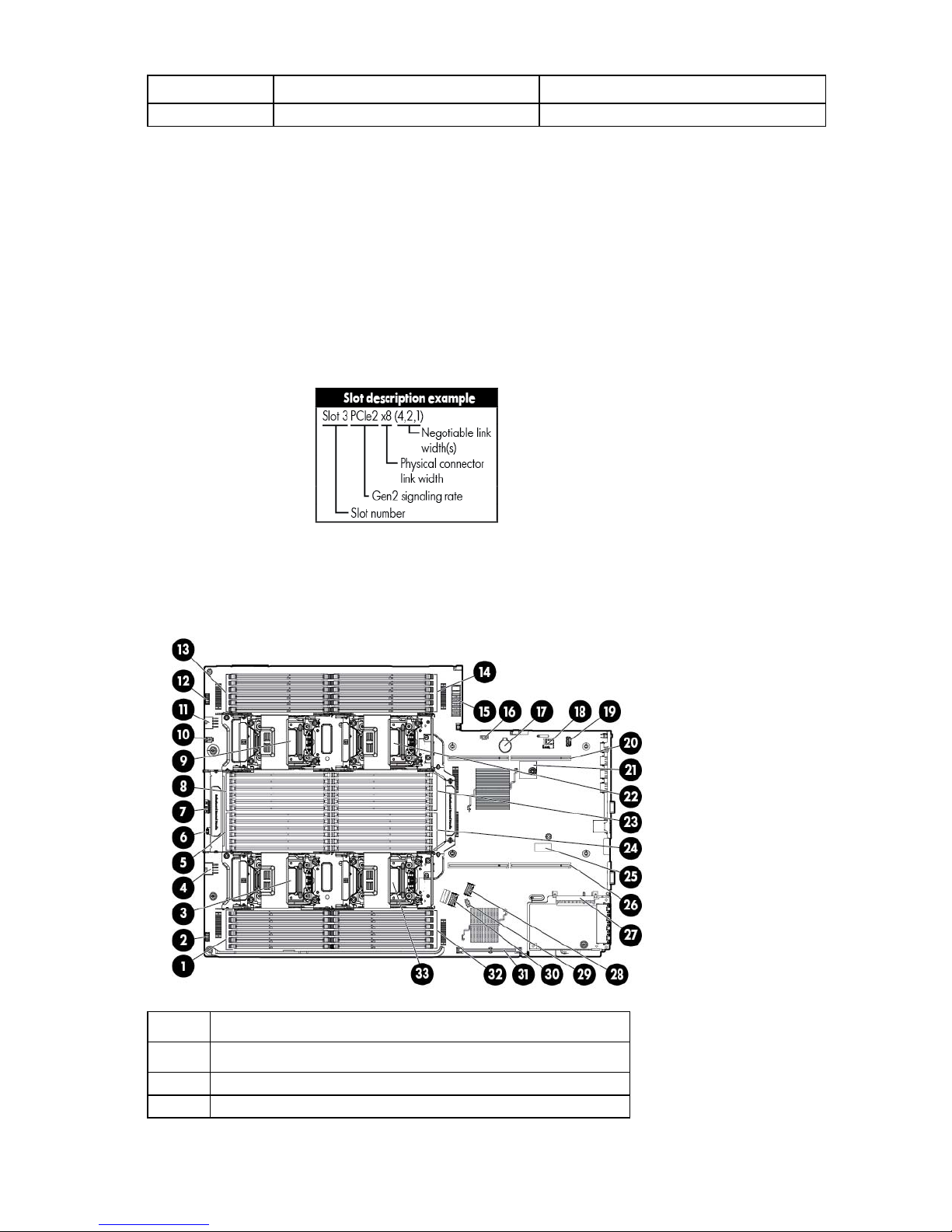
Slot PCIe 3-slot riser cage* PCIe 2-slot x16 riser cage
6 - HL/FH
*Depending on the server model, the server might ship with one or two riser cages installed.
**These slots can run 8 GT/s signaling rate in either PCIe2 or PCIe3 mode, depending on the capability of the installed
processor.
†PCIe slot 3 is connected to the southbridge and runs at the Gen2 signaling rate.
Notes:
"Primary" denotes the riser cage is installed in the primary riser connector.
"Secondary" denotes the riser cage is installed in the secondary riser connector.
Installing the riser cages listed in the table above in either the primary or secondary riser connectors determines the form
factor of the PCIe cards supported by those riser cages.
FL/FH denotes full-length, full-height. HL/FH denotes half-length, full-height. LP denotes low profile.
The PCIe 2-slot x16 riser cage supports a maximum power of 150 W with an HP power cable. This cable must be used
for PCIe card wattages greater than 75 W.
PCIe2 or PCIe3** x8 (8,4,2,1) —
System board components
Item Description
1
2
3
Processor 3 DIMM slots (7-12)
Front power switch
Processor 3 socket
Component identification 11
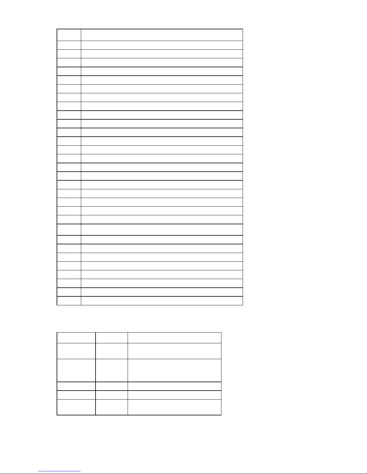
5
10
15
22
30
Item Description
4
6
7
8
9
11
12
13
14
16
17
18
19
20
21
23
24
25
26
27
28
29
31
32
33
Drive cage power connector 2
Processor 3 DIMM slots (1-6)
Systems Insight Display connector
Sideband signal connector
Processor 4 DIMM slots (7-12)
Processor 4 socket
Discovery services connector
Drive cage power connector 1
Front video connector
Processor 4 DIMM slots (1-6)
Processor 2 DIMM slots (1-6)
Power supply backplane connector
USB connector 1
System battery
MicroSD card slot
Internal USB connector
Secondary (processor 2) PCIe riser connector
TPM connector
Processor 2 socket
Processor 2 DIMM slots (7-12)
Processor 1 DIMM slots (1-6)
System maintenance switch
Primary (processor 1) PCIe riser connector
FlexibleLOM slot
SAS connector 1
USB connector 2
SAS connector 2
Cache module connector
Processor 1 DIMM slots (7-12)
Processor 1 socket
System maintenance switch
Position Default Function
S1
S2
S3
S4
S5
Off Off = iLO security is enabled.
Off Off = System configuration can be
Off Reserved
Off Reserved
Off Off = Power-on password is enabled.
On = iLO security is disabled.
changed.
On = System configuration is locked.
On = Power-on password is disabled.
Component identification 12
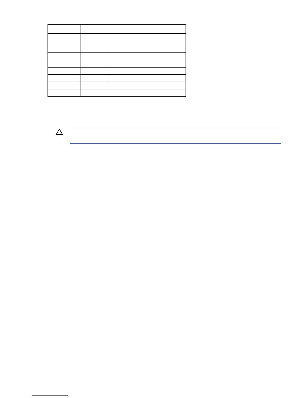
On = ROM reads system configuration
S12
Position Default Function
S6
S7
S8
S9
S10
S11
Off Off = No function
as invalid.
— Reserved
— Reserved
— Reserved
— Reserved
— Reserved
— Reserved
To access the redundant ROM, set S1, S5, and S6 to on.
When the system maintenance switch position 6 is set to the On position, the system is prepared to erase all
system configuration settings from both CMOS and NVRAM.
CAUTION: Clearing CMOS and/or NVRAM deletes configuration information. Be sure to
properly configure the server or data loss could occur.
NMI functionality
An NMI crash dump enables administrators to create crash dump files when a system is hung and not
responding to traditional debug mechanisms.
Crash dump log analysis is an essential part of diagnosing reliability problems, such as hangs in operating
systems, device drivers, and applications. Many crashes freeze a system, and the only available action for
administrators is to cycle the system power. Resetting the system erases any information that could support
problem analysis, but the NMI feature preserves that information by performing a memory dump before a
hard reset.
To force the OS to invoke the NMI handler and generate a crash dump log, the administrator can use the iLO
Virtual NMI feature.
For more information, see the HP website (http://www.hp.com/support/NMI).
Component identification 13
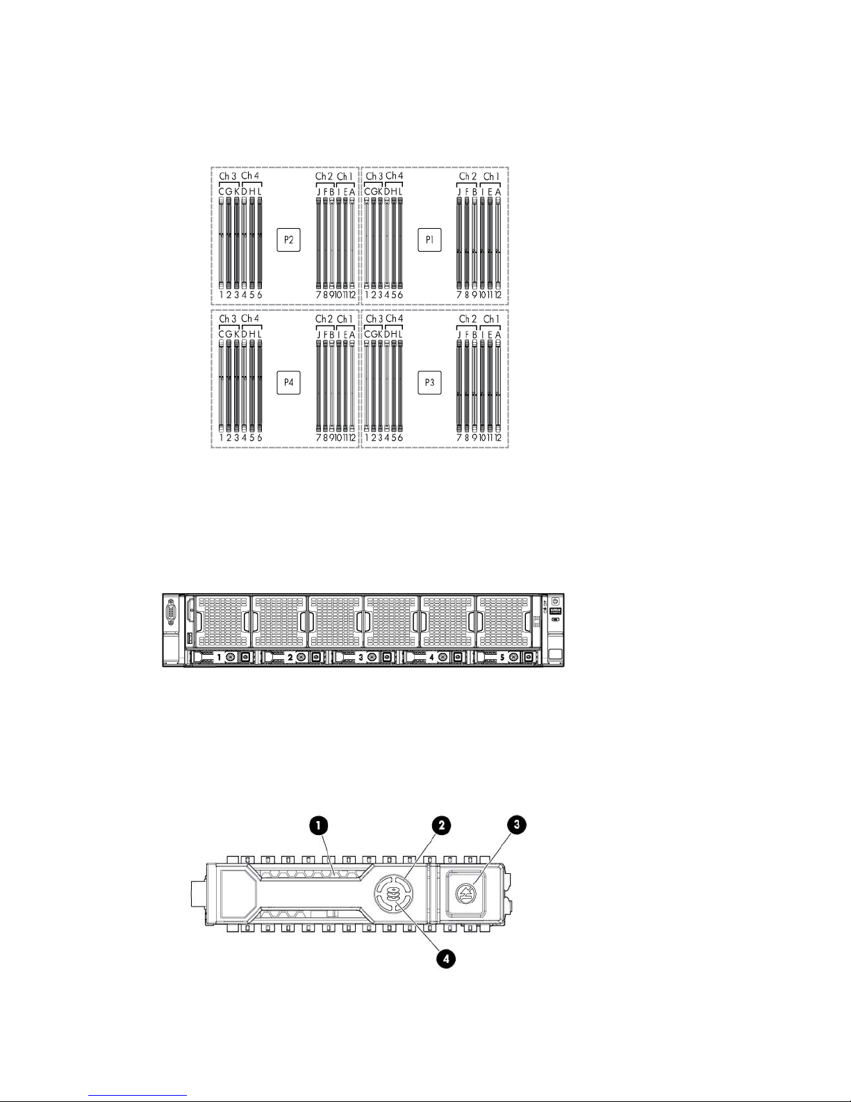
DIMM slot locations
DIMM slots are numbered sequentially (1 through 12) for each processor. The supported AMP modes use the
letter assignments for population guidelines.
Hot-plug drive bay numbering
Hot-plug drive LED definitions
Component identification 14
drive is rebuilding or performing a RAID migration, strip size
Item LED Status Definition
1
2
3
4
Locate Solid blue The drive is being identified by a host application.
Flashing blue The drive carrier firmware is being updated or requires an update.
Activity ring Rotating green Drive activity
Off No drive activity
Do not remove Solid white Do not remove the drive. Removing the drive causes one or more of
the logical drives to fail.
Off Removing the drive does not cause a logical drive to fail.
Drive status Solid green The drive is a member of one or more logical drives.
Flashing green The
migration, capacity expansion, or logical drive extension, or is
erasing.
Flashing
amber/green
The drive is a member of one or more logical drives and predicts
the drive will fail.
Flashing amber The drive is not configured and predicts the drive will fail.
Solid amber The drive has failed.
Off The drive is not configured by a RAID controller.
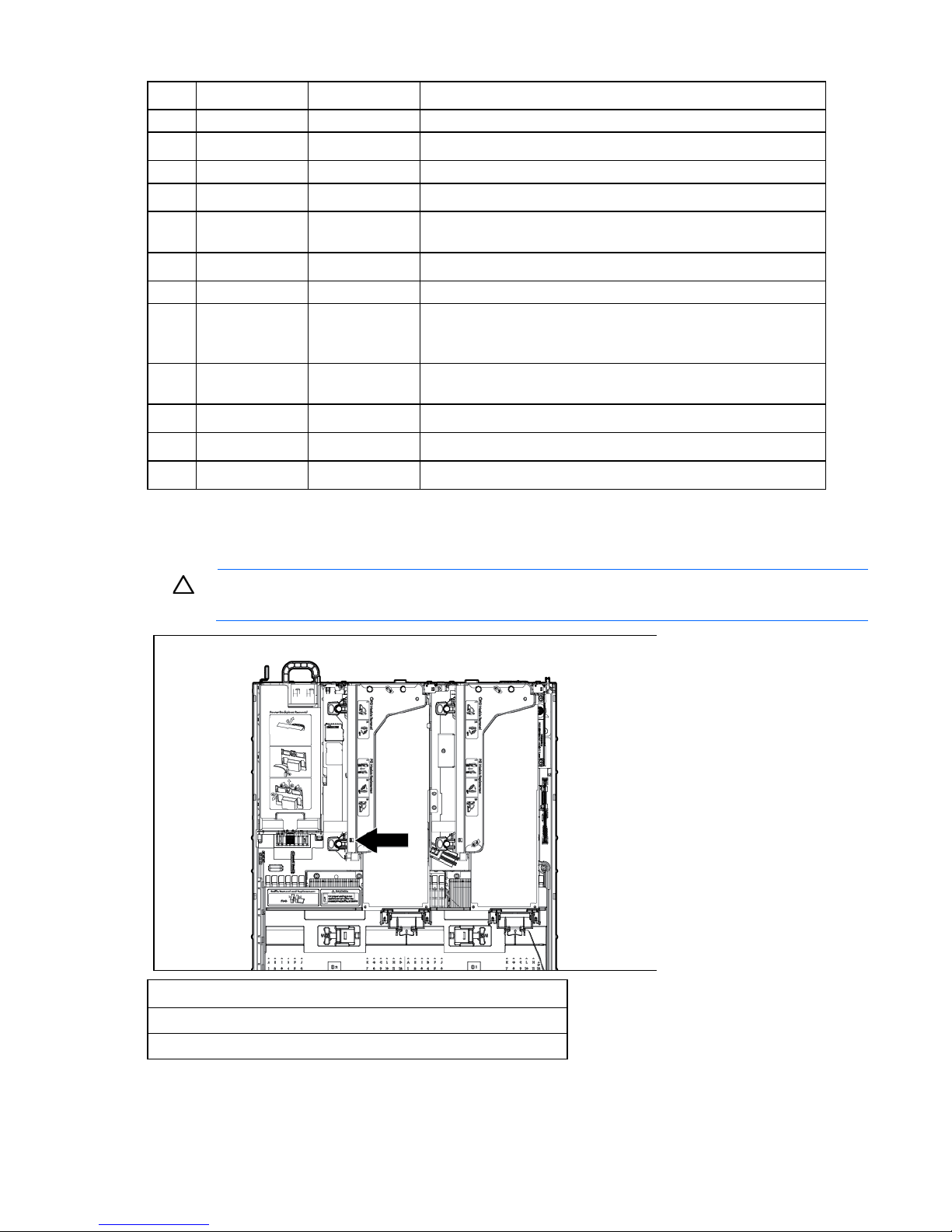
PCIe riser cage LED
CAUTION: To prevent damage to the server or expansion boards, power down the server and
Status
On = AC power is connected.
Off = AC power is disconnected.
remove all AC power cords before removing or installing the PCI riser cage.
Component identification 15
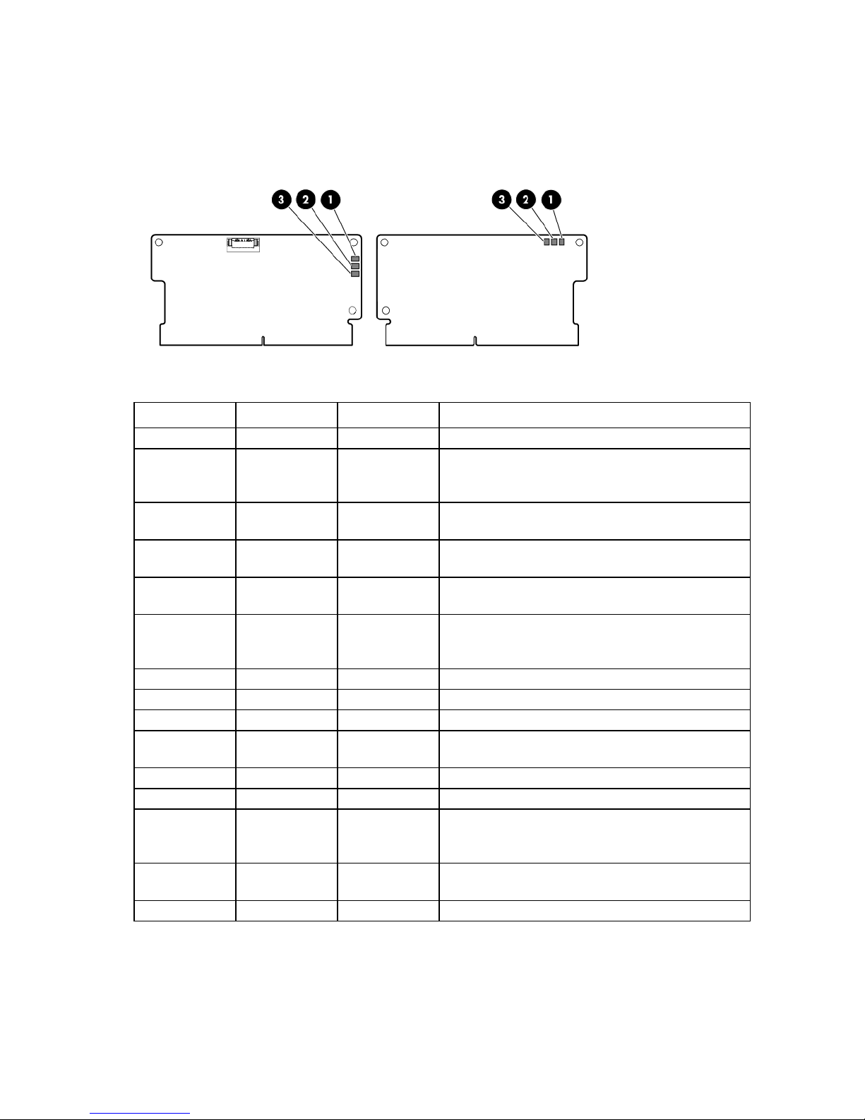
FBWC module LEDs (P222, P420, P421)
Off
The FBWC module has three single-color LEDs (one amber and two green). The LEDs are duplicated on the
reverse side of the cache module to facilitate status viewing.
1 - Amber 2 - Green 3 - Green Interpretation
Off
Off
Off
Off
Off
Off
Off
Flashing 1 Hz
Flashing 1 Hz
Flashing 1 Hz
Flashing 2 Hz
Flashing 2 Hz
On
On
Off Off The cache module is not powered.
Flashing 0.5 Hz Flashing 0.5 Hz The cache microcontroller is executing from within its
boot loader and receiving new flash code from the host
controller.
Flashing 1 Hz Flashing 1 Hz The cache module is powering up, and the capacitor
pack is charging.
Off Flashing 1 Hz The cache module is idle, and the capacitor pack is
charging.
Off On The cache module is idle, and the capacitor pack is
charged.
On On The cache module is idle, the capacitor pack is charged,
and the cache contains data that has not yet been
written to the drives.
Flashing 1 Hz Off A backup is in progress.
On Off The current backup is complete with no errors.
Flashing 1 Hz Off The current backup failed, and data has been lost.
Flashing 1 Hz On A power error occurred during the previous or current
boot. Data may be corrupt.
On Off An overtemperature condition exists.
Flashing 2 Hz Off The capacitor pack is not attached.
Flashing 2 Hz On The capacitor has been charging for 10 minutes, but
has not reached sufficient charge to perform a full
backup.
On Off The current backup is complete, but power fluctuations
occurred during the backup.
On On The cache module microcontroller has failed.
Hot-plug fans
Component identification 16
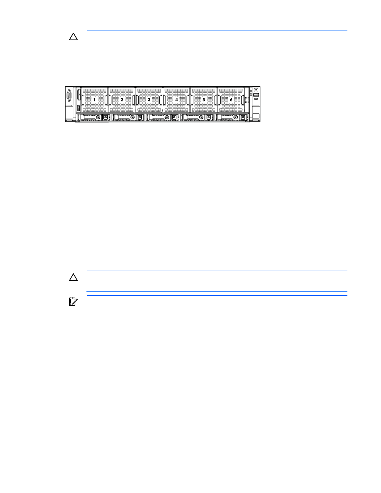
CAUTION: To avoid damage to server components, all fan modules must be installed in fan bays
for any processor configuration.
For all processor configurations, the HP ProLiant DL560 Gen8 Server requires six fan modules for
redundancy. A fan failure causes a loss of cooling redundancy. A second fan failure or a missing fan module
causes an orderly shutdown of the server.
The server supports variable fan speeds. The fans operate at minimum speed until a temperature change
requires a fan speed increase to cool the server.
The server shuts down in the following temperature-related scenarios:
• At POST and in the OS, iLO performs an orderly shutdown if a cautionary temperature level is detected.
If the server hardware detects a critical temperature level before an orderly shutdown occurs, the server
performs an immediate shutdown.
• When the Thermal Shutdown feature is disabled in RBSU, iLO does not perform an orderly shutdown
when a cautionary temperature level is detected. Disabling this feature does not disable the server
hardware from performing an immediate shutdown when a critical temperature level is detected.
CAUTION: A thermal event can damage server components when the Thermal Shutdown feature
is disabled in RBSU.
IMPORTANT: An immediate shutdown is a hardware-controlled function and it overrides any
firmware or software actions.
Component identification 17

Operations
Power up the server
To power up the server, press the Power On/Standby button.
Power down the server
Before powering down the server for any upgrade or maintenance procedures, perform a backup of critical
server data and programs.
IMPORTANT: When the server is in standby mode, auxiliary power is still being provided to the
To power down the server, use one of the following methods:
• Press and release the Power On/Standby button.
• Press and hold the Power On/Standby button for more than 4 seconds to force the server to enter
• Use a virtual power button selection through iLO.
system.
This method initiates a controlled shutdown of applications and the OS before the server enters standby
mode.
standby mode.
This method forces the server to enter standby mode without properly exiting applications and the OS.
If an application stops responding, you can use this method to force a shutdown.
This method initiates a controlled remote shutdown of applications and the OS before the server enters
standby mode.
Before proceeding, verify the server is in standby mode by observing that the system power LED is amber.
Extend the server from the rack
WARNING: To reduce the risk of personal injury or equipment damage, be sure that the rack is
1. Pull down the quick release levers on each side of the server.
adequately stabilized before extending a component from the rack.
Operations 18
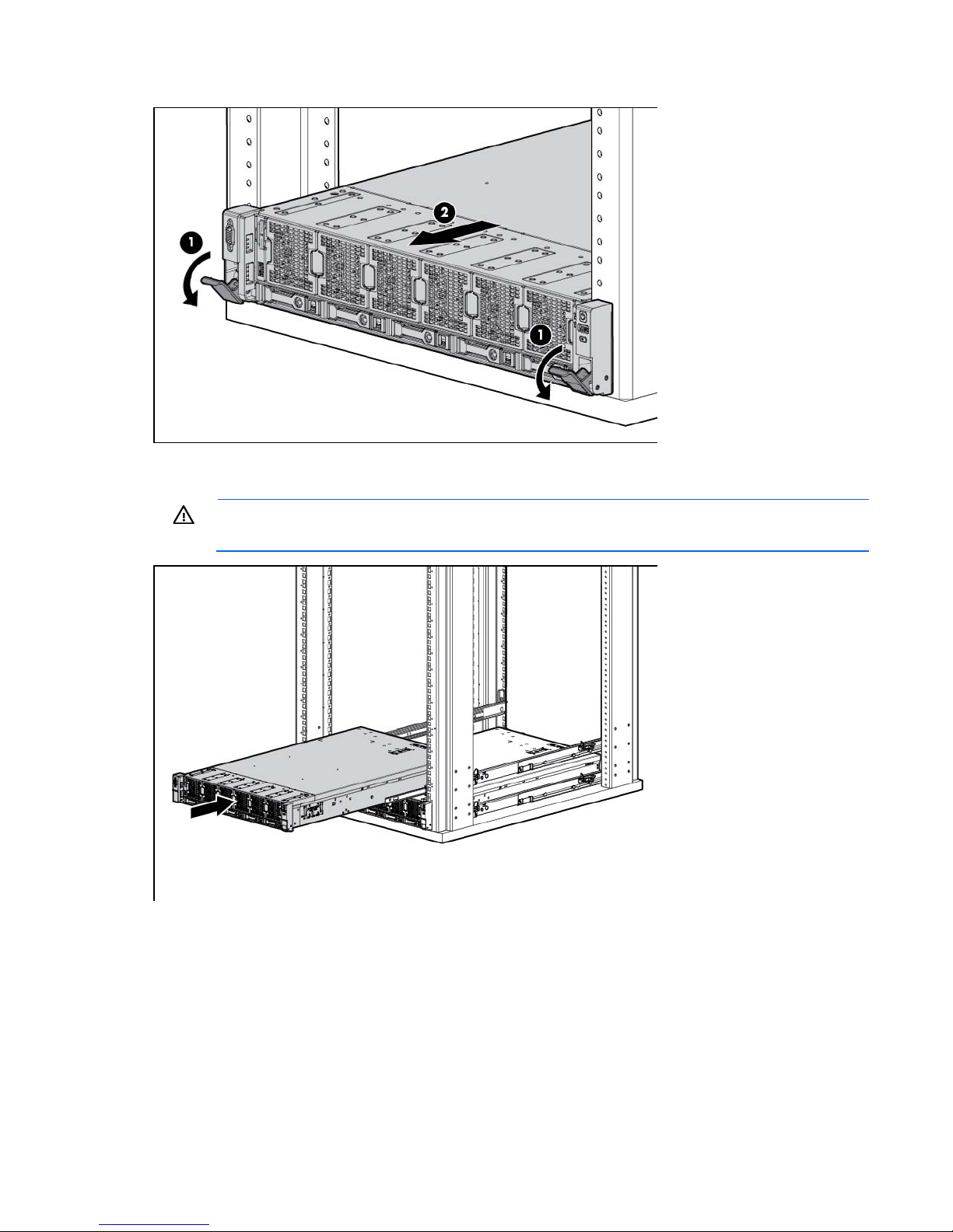
2.
Extend the server from the rack.
3. After performing the installation or maintenance procedure, slide the server back into the rack, and then
press the server firmly into the rack to secure it in place.
WARNING: To reduce the risk of personal injury, be careful when pressing the server rail-release
latches and sliding the server into the rack. The sliding rails could pinch your fingers.
Access the Systems Insight Display
To access the HP Systems Insight Display:
1. Press and release the panel.
Operations 19

2.
After the display fully ejects, rotate the display sideways to view the LEDs.
Remove the access panel
WARNING: To reduce the risk of personal injury from hot surfaces, allow the drives and the
To remove the component:
1. Power down the server (on page 18).
2. Remove all power:
internal system components to cool before touching them.
WARNING: To reduce the risk of personal injury, electric shock, or damage to the equipment,
remove the power cord to remove power from the server. The front panel Power On/Standby
button does not completely shut off system power. Portions of the power supply and some internal
circuitry remain active until AC power is removed.
CAUTION: For proper cooling, do not operate the server without the access panel, baffles,
expansion slot covers, or blanks installed. If the server supports hot-plug components, minimize
the amount of time the access panel is open.
a. Disconnect each power cord from the power source.
b. Disconnect each power cord from the server.
3. Extend the server from the rack (on page 18).
4. Use a T-15 Torx screwdriver to loosen the security screw on the hood latch.
5. Lift up on the hood latch handle, and then remove the access panel.
Install the access panel
1. Place the access panel on top of the server with the hood latch open. Allow the panel to extend past the
rear of the server approximately 1.25 cm (0.5 in).
2. Push down on the hood latch. The access panel slides to a closed position.
Operations 20
3.
Use a T-15 Torx screwdriver to tighten the security screw on the hood latch.
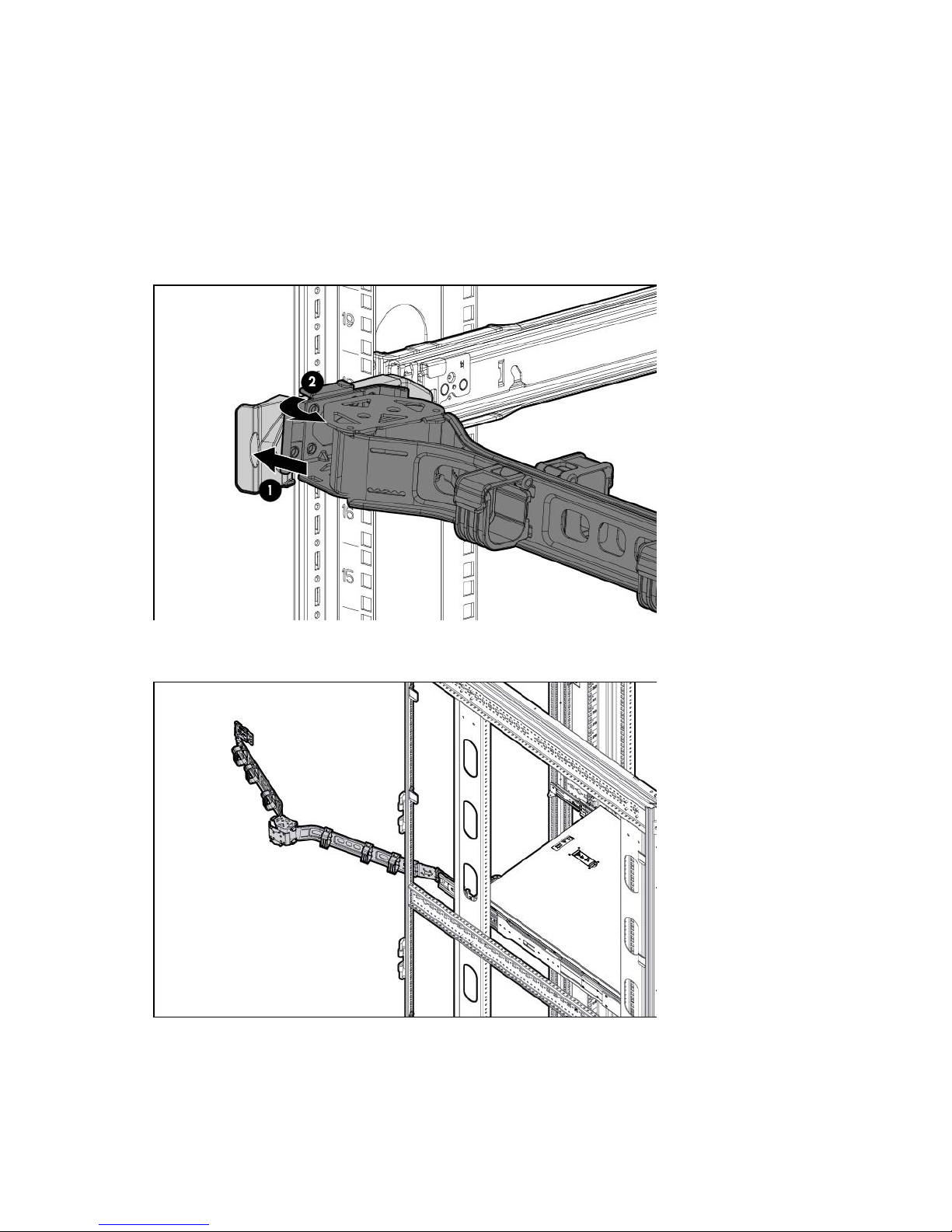
Access the product rear panel
Opening the cable management arm
To access the server rear panel:
1. Release the cable management arm.
2. Open the cable management arm. Note that the cable management arm can be right-mounted or
left-mounted.
Remove the primary PCIe riser cage
Operations 21
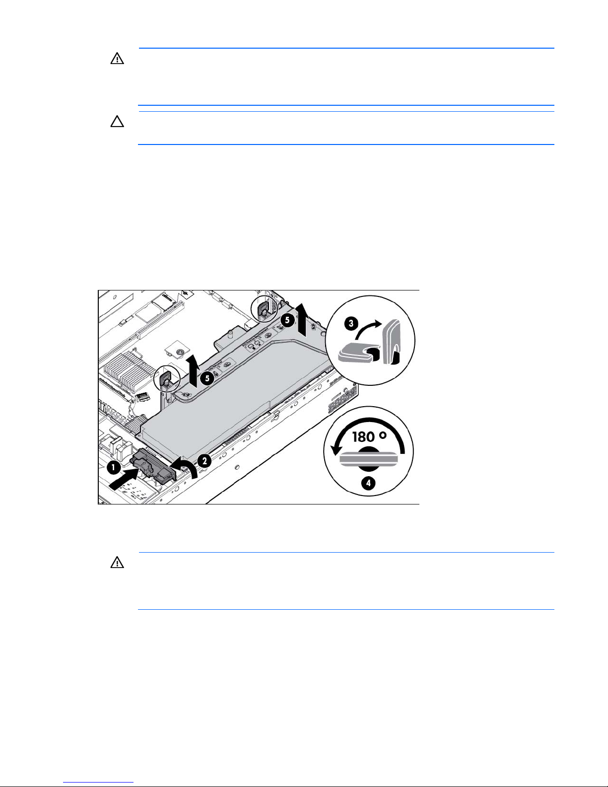
WARNING: To reduce the risk of personal injury, electric shock, or damage to the equipment,
remove the power cord to remove power from the server. The front panel Power On/Standby
button does not completely shut off system power. Portions of the power supply and some internal
circuitry remain active until AC power is removed.
CAUTION: To prevent damage to the server or expansion boards, power down the server and
remove all AC power cords before removing or installing the PCI riser cage.
1. Power down the server (on page 18).
2. Remove all power:
a. Disconnect each power cord from the power source.
b. Disconnect each power cord from the server.
3. Extend the server from the rack (on page 18).
4. Remove the access panel (on page 20).
5. If any full-length expansion boards are installed, release the full-length expansion board retainer.
6. Remove the PCIe riser cage.
Install the primary PCIe riser cage
WARNING: To reduce the risk of personal injury, electric shock, or damage to the equipment,
remove the power cord to remove power from the server. The front panel Power On/Standby
button does not completely shut off system power. Portions of the power supply and some internal
1. Power down the server (on page 18).
2. Remove all power:
3. Extend the server from the rack (on page 18).
4. Remove the access panel (on page 20).
circuitry remain active until AC power is removed.
a. Disconnect each power cord from the power source.
b. Disconnect each power cord from the server.
Operations 22
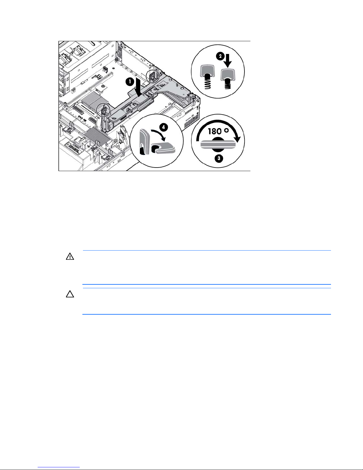
5.
Install the PCIe riser cage.
6. Install the access panel (on page 20).
7. Install the server into the rack ("Installing the server into the rack" on page 30).
8. Connect each power cord to the server.
9. Connect each power cord to the power source.
10. Power up the server (on page 18).
Remove the air baffle
WARNING: To reduce the risk of personal injury, electric shock, or damage to the equipment,
remove the power cord to remove power from the server. The front panel Power On/Standby
button does not completely shut off system power. Portions of the power supply and some internal
To remove the component:
1. Power down the server (on page 18).
2. Remove all power:
circuitry remain active until AC power is removed.
CAUTION: For proper cooling, do not operate the server without the access panel, baffles,
expansion slot covers, or blanks installed. If the server supports hot-plug components, minimize
the amount of time the access panel is open.
a. Disconnect each power cord from the power source.
b. Disconnect each power cord from the server.
3. Extend the server from the rack (on page 18).
4. Remove the access panel (on page 20).
5. If any full-length expansion boards are installed, release the full-length expansion board retainer, and
then remove the PCIe riser cage ("Remove the primary PCIe riser cage" on page 21).
Operations 23
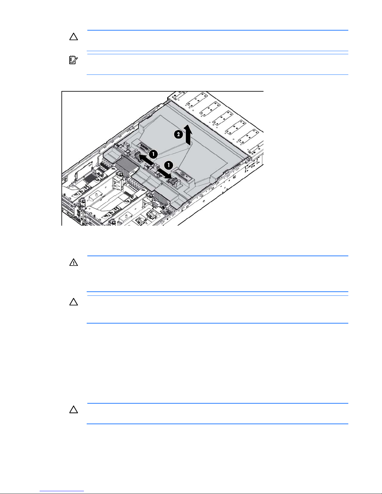
CAUTION: Do not detach the cable that connects the battery pack to the cache module.
Detaching the cable causes any unsaved data in the cache module to be lost.
IMPORTANT: It is necessary to remove the PCI riser cage only if there is a full-length expansion
board installed.
6. Remove the air baffle.
Install the air baffle
WARNING: To reduce the risk of personal injury, electric shock, or damage to the equipment,
remove the power cord to remove power from the server. The front panel Power On/Standby
button does not completely shut off system power. Portions of the power supply and some internal
To install the component:
1. Power down the server (on page 18).
2. Remove all power:
3. Extend the server from the rack (on page 18).
4. Remove the access panel (on page 20).
circuitry remain active until AC power is removed.
CAUTION: For proper cooling, do not operate the server without the access panel, baffles,
expansion slot covers, or blanks installed. If the server supports hot-plug components, minimize
the amount of time the access panel is open.
a. Disconnect each power cord from the power source.
b. Disconnect each power cord from the server.
CAUTION: Do not detach the cable that connects the battery pack to the cache module.
Detaching the cable causes any unsaved data in the cache module to be lost.
Operations 24
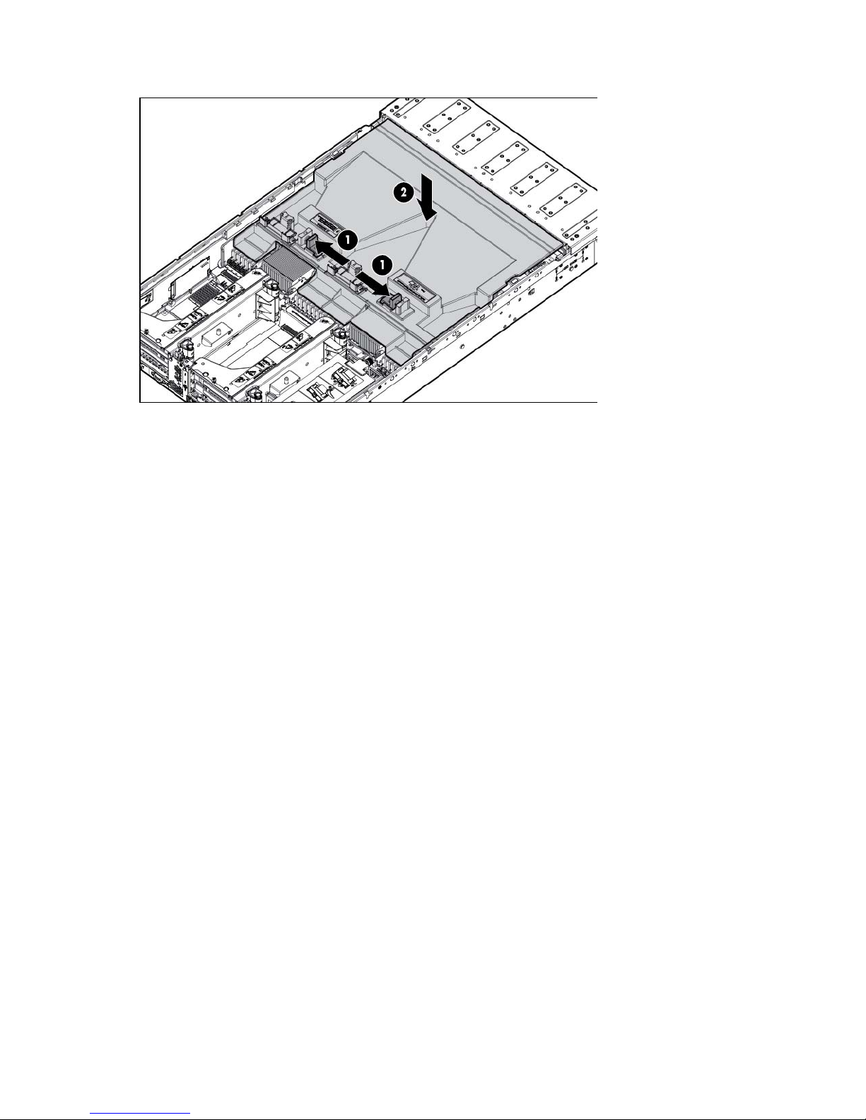
5.
Install the air baffle.
6. Install the access panel (on page 20).
7. Install the server into the rack ("Installing the server into the rack" on page 30).
8. Connect each power cord to the server.
9. Connect each power cord to the power source.
10. Power up the server (on page 18).
Operations 25

Setup
Optional installation services
Delivered by experienced, certified engineers, HP Care Pack services help you keep your servers up and
running with support packages tailored specifically for HP ProLiant systems. HP Care Packs let you integrate
both hardware and software support into a single package. A number of service level options are available
to meet your needs.
HP Care Pack Services offer upgraded service levels to expand your standard product warranty with
easy-to-buy, easy-to-use support packages that help you make the most of your server investments. Some of
the Care Pack services are:
• Hardware support
o 6-Hour Call-to-Repair
o 4-Hour 24x7 Same Day
o 4-Hour Same Business Day
• Software support
o Microsoft®
o Linux
o HP ProLiant Essentials (HP SIM and RDP)
o VMware
• Integrated hardware and software support
o Critical Service
o Proactive 24
o Support Plus
o Support Plus 24
• Startup and implementation services for both hardware and software
For more information on HP Care Pack Services, see the HP website
(http://www.hp.com/services/carepack).
Optimum environment
When installing the server in a rack, select a location that meets the environmental standards described in
this section.
Space and airflow requirements
To allow for servicing and adequate airflow, observe the following space and airflow requirements when
deciding where to install a rack:
Setup 26

• Leave a minimum clearance of 63.5 cm (25 in) in front of the rack.
• Leave a minimum clearance of 76.2 cm (30 in) behind the rack.
• Leave a minimum clearance of 121.9 cm (48 in) from the back of the rack to the back of another rack
or row of racks.
HP servers draw in cool air through the front door and expel warm air through the rear door. Therefore, the
front and rear rack doors must be adequately ventilated to allow ambient room air to enter the cabinet, and
the rear door must be adequately ventilated to allow the warm air to escape from the cabinet.
CAUTION: To prevent improper cooling and damage to the equipment, do not block the
When vertical space in the rack is not filled by a server or rack component, the gaps between the
components cause changes in airflow through the rack and across the servers. Cover all gaps with blanking
panels to maintain proper airflow.
The 9000 and 10000 Series Racks provide proper server cooling from flow-through perforations in the front
and rear doors that provide 64 percent open area for ventilation.
ventilation openings.
CAUTION: Always use blanking panels to fill empty vertical spaces in the rack. This arrangement
ensures proper airflow. Using a rack without blanking panels results in improper cooling that can
lead to thermal damage.
CAUTION: When using a Compaq branded 7000 series rack, install the high airflow rack door
insert (PN 327281-B21 for 42U rack, PN 157847-B21 for 22U rack) to provide proper
front-to-back airflow and cooling.
CAUTION: If a third-party rack is used, observe the following additional requirements to ensure
adequate airflow and to prevent damage to the equipment:
• Front and rear doors—If the 42U rack includes closing front and rear doors, you must allow
5,350 sq cm (830 sq in) of holes evenly distributed from top to bottom to permit adequate
airflow (equivalent to the required 64 percent open area for ventilation).
• Side—The clearance between the installed rack component and the side panels of the rack
must be a minimum of 7 cm (2.75 in).
IMPORTANT: The HP ProLiant DL560 Gen8 Server cable management arm is not supported on
Compaq branded 7000 series racks.
Temperature requirements
To ensure continued safe and reliable equipment operation, install or position the system in a well-ventilated,
climate-controlled environment.
The maximum recommended ambient operating temperature (TMRA) for most server products is 35°C
(95°F). The temperature in the room where the rack is located must not exceed 35°C (95°F).
CAUTION: To reduce the risk of damage to the equipment when installing third-party options:
• Do not permit optional equipment to impede airflow around the server or to increase the
internal rack temperature beyond the maximum allowable limits.
• Do not exceed the manufacturer’s TMRA.
Setup 27

Power requirements
Installation of this equipment must comply with local and regional electrical regulations governing the
installation of information technology equipment by licensed electricians. This equipment is designed to
operate in installations covered by NFPA 70, 1999 Edition (National Electric Code) and NFPA-75, 1992
(code for Protection of Electronic Computer/Data Processing Equipment). For electrical power ratings on
options, refer to the product rating label or the user documentation supplied with that option.
WARNING: To reduce the risk of personal injury, fire, or damage to the equipment, do not
overload the AC supply branch circuit that provides power to the rack. Consult the electrical
When installing more than one server, you may need to use additional power distribution devices to safely
provide power to all devices. Observe the following guidelines:
• Balance the server power load between available AC supply branch circuits.
• Do not allow the overall system AC current load to exceed 80% of the branch circuit AC current rating.
authority having jurisdiction over wiring and installation requirements of your facility.
CAUTION: Protect the server from power fluctuations and temporary interruptions with a
regulating uninterruptible power supply. This device protects the hardware from damage caused
by power surges and voltage spikes and keeps the system in operation during a power failure.
• Do not use common power outlet strips for this equipment.
• Provide a separate electrical circuit for the server.
Electrical grounding requirements
The server must be grounded properly for proper operation and safety. In the United States, you must install
the equipment in accordance with NFPA 70, 1999 Edition (National Electric Code), Article 250, as well as
any local and regional building codes. In Canada, you must install the equipment in accordance with
Canadian Standards Association, CSA C22.1, Canadian Electrical Code. In all other countries, you must
install the equipment in accordance with any regional or national electrical wiring codes, such as the
International Electrotechnical Commission (IEC) Code 364, parts 1 through 7. Furthermore, you must be sure
that all power distribution devices used in the installation, such as branch wiring and receptacles, are listed
or certified grounding-type devices.
Because of the high ground-leakage currents associated with multiple servers connected to the same power
source, HP recommends the use of a PDU that is either permanently wired to the building’s branch circuit or
includes a nondetachable cord that is wired to an industrial-style plug. NEMA locking-style plugs or those
complying with IEC 60309 are considered suitable for this purpose. Using common power outlet strips for
the server is not recommended.
Connecting a DC power cable to a DC power source
WARNING: To reduce the risk of electric shock or energy hazards:
• This equipment must be installed by trained service personnel, as defined by the NEC and IEC
60950-1, Second Edition, the standard for Safety of Information Technology Equipment.
• Connect the equipment to a reliably grounded SELV source. An SELV source is a secondary
circuit that is designed so normal and single fault conditions do not cause the voltages to
exceed a safe level (60 V direct current).
• The branch circuit overcurrent protection must be rated 20A.
Setup 28
WARNING: When installing a DC power supply, the ground wire must be connected before the
supply circuit and the earthing conductor, and also the point of earthing of the DC system. The
positive or negative leads.
WARNING: Remove power from the power supply before performing any installation steps or
maintenance on the power supply.
CAUTION: The server equipment connects the earthed conductor of the DC supply circuit to the
earthing conductor at the equipment. For more information, see the HP 750W Common Slot -48V
DC Input Hot-Plug Power Supply Kit Installation Instructions.
CAUTION: If the DC connection exists between the earthed conductor of the DC supply circuit and
the earthing conductor at the server equipment, the following conditions must be met:
• This equipment must be connected directly to the DC supply system earthing electrode
conductor or to a bonding jumper from an earthing terminal bar or bus to which the DC supply
system earthing electrode conductor is connected.
• This equipment should be located in the same immediate area (such as adjacent cabinets) as
any other equipment that has a connection between the earthed conductor of the same DC
DC system should be earthed elsewhere.
• The DC supply source is to be located within the same premises as the equipment.
• Switching or disconnecting devices should not be in the earthed circuit conductor between the
DC source and the point of connection of the earthing electrode conductor.
To connect a DC power cable to a DC power source:
1. Cut the DC power cord ends no shorter than 150 cm (59.06 in).
2. If the power source requires ring tongues, use a crimping tool to install the ring tongues on the power
cord wires.
IMPORTANT: The ring tongues must be UL approved and accommodate 12 gauge wires.
IMPORTANT: The minimum nominal thread diameter of a pillar or stud type terminal must be 3.5
mm (0.138 in); the diameter of a screw type terminal must be 4.0 mm (0.157 in).
3. Stack each same-colored pair of wires and then attach them to the same power source. The power cord
consists of three wires (black, red, and green).
For more information, see the HP 750W Common Slot -48V DC Input Hot-Plug Power Supply Installation
Instructions.
Rack warnings
WARNING: To reduce the risk of personal injury or damage to the equipment, be sure that:
• The leveling jacks are extended to the floor.
• The full weight of the rack rests on the leveling jacks.
• The stabilizing feet are attached to the rack if it is a single-rack installation.
• The racks are coupled together in multiple-rack installations.
• Only one component is extended at a time. A rack may become unstable if more than one
component is extended for any reason.
Setup 29

WARNING: To reduce the risk of personal injury or equipment damage when unloading a rack:
Never stand in front of the rack when it is rolling down the ramp from the pallet. Always handle
To reduce the risk of electric shock, fire, or damage to the equipment, do not plug
• At least two people are needed to safely unload the rack from the pallet. An empty 42U rack
can weigh as much as 115 kg (253 lb), can stand more than 2.1 m (7 ft) tall, and might
become unstable when being moved on its casters.
•
the rack from both sides.
Identifying the contents of the server shipping carton
Unpack the server shipping carton and locate the materials and documentation necessary for installing the
server. All the rack mounting hardware necessary for installing the server into the rack is included with the
rack or the server.
The contents of the server shipping carton include:
• Server
• Power cord
• Hardware documentation, Documentation CD, and software products
• Rack-mounting hardware
In addition to the supplied items, you might need:
• Operating system or application software
• Hardware options
Installing hardware options
Install any hardware options before initializing the server. For options installation information, refer to the
option documentation. For server-specific information, refer to "Hardware options installation (on page 34)."
Installing the server into the rack
CAUTION: Always plan the rack installation so that the heaviest item is on the bottom of the rack.
1. Install the server and cable management arm into the rack. For more information, see the installation
2. Connect peripheral devices to the server. For information on identifying connectors, see "Rear panel
3. Connect the power cord to the rear of the server.
Install the heaviest item first, and continue to populate the rack from the bottom to the top.
instructions that ship with the 2U Quick Deploy Rail System.
components (on page 9)."
WARNING:
telephone or telecommunications connectors into RJ-45 connectors.
Setup 30
 Loading...