

Page 1

HPE ProLiant DL560 Gen10 Server
Maintenance and Service Guide
Abstract
This document is for the person who installs, administers, and troubleshoots servers and storage systems.
Hewlett Packard Enterprise assumes that you are qualified in the servicing of computer equipment, and trained in
recognizing hazards in products with hazardous energy levels.
Part Number: 876291-401
Published: December 2019
Edition: 10
Page 2

©
Copyright 2017—2019 Hewlett Packard Enterprise Development LP
Notices
The information contained herein is subject to change without notice. The only warranties for Hewlett Packard Enterprise
products and services are set forth in the express warranty statements accompanying such products and services. Nothing
herein should be construed as constituting an additional warranty. Hewlett Packard Enterprise shall not be liable for technical
or editorial errors or omissions contained herein.
Confidential computer software. Valid license from Hewlett Packard Enterprise required for possession, use, or copying.
Consistent with FAR 12211 and 12212, Commercial Computer Software, Computer Software Documentation, and Technical
Data for Commercial Items are licensed to the U.S. Government under vendor's standard commercial license.
Links to third-party websites take you outside the Hewlett Packard Enterprise website. Hewlett Packard Enterprise has no
control over and is not responsible for information outside the Hewlett Packard Enterprise website.
Acknowledgments
Microsoft® and Windows® are either registered trademarks or trademarks of Microsoft Corporation in the United States
and/or other countries.
Intel®, Optane®, Xeon®, and the Intel Inside logo are trademarks of Intel Corporation in the U.S. and other countries.
Linux® is the registered trademark of Linus Torvalds in the U.S. and other countries.
Red Hat® is a registered trademark of Red Hat, Inc. in the United States and other countries.
Page 3

Contents
Illustrated parts catalog.........................................................................................................7
Mechanical components.........................................................................................................................................................................................................7
Access panel spare part........................................................................................................................................................................................7
Air bale spare part.................................................................................................................................................................................................8
Fan cage spare parts...............................................................................................................................................................................................8
PCIe riser cage spare parts..................................................................................................................................................................................8
2U bezel ear spare parts.......................................................................................................................................................................................8
2U bezel spare part................................................................................................................................................................................................. 8
Fan spare parts.......................................................................................................................................................................................................... 9
Mezzanine bracket spare part...........................................................................................................................................................................9
HPE Smart Storage Battery latch and retainer spare part...............................................................................................................9
Miscellaneous blank spare parts......................................................................................................................................................................9
Rack mounting and cable management spare parts............................................................................................................................9
System components.............................................................................................................................................................................................................. 10
DIMM spare parts.................................................................................................................................................................................................. 10
HPE 16GB NVDIMM spare part.................................................................................................................................................................... 11
HPE Persistent Memory module spare parts........................................................................................................................................ 11
Processor spare parts..........................................................................................................................................................................................11
Heatsink spare parts............................................................................................................................................................................................14
Power supply spare parts................................................................................................................................................................................. 15
Controller spare parts......................................................................................................................................................................................... 15
PCIe riser board spare parts............................................................................................................................................................................18
FlexibleLOM adapter spare parts.................................................................................................................................................................18
System board spare parts.................................................................................................................................................................................18
System battery spare part................................................................................................................................................................................18
Server options........................................................................................................................................................................................................................... 19
Drive spare parts....................................................................................................................................................................................................19
Drive cage backplane spare parts................................................................................................................................................................27
Chassis Intrusion Detection Switch spare part.....................................................................................................................................27
Accelerator and GPU spare parts.................................................................................................................................................................27
12G SAS expander board spare part......................................................................................................................................................... 28
HPE Smart Storage Battery spare part.....................................................................................................................................................28
HPE Smart Storage Hybrid Capacitor spare part............................................................................................................................... 28
Power module/System Insight Display spare parts...........................................................................................................................28
Universal media bay spare part.....................................................................................................................................................................29
CPU Mezzanine UPI performance kit spare part.................................................................................................................................29
Processor mezzanine tray spare part........................................................................................................................................................ 29
4-port NVMe mezzanine card spare part................................................................................................................................................29
HPE Trusted Platform Module
microSD spare parts.............................................................................................................................................................................................29
Cable spare parts................................................................................................................................................................................................... 30
20 spare part..................................................................................................................................... 29
Customer self repair............................................................................................................. 31
Removal and replacement procedures..............................................................................40
Required tools........................................................................................................................................................................................................................... 40
3
Page 4

Safety considerations............................................................................................................................................................................................................40
Symbols on equipment.......................................................................................................................................................................................40
Server warnings and cautions........................................................................................................................................................................ 41
Preventing electrostatic discharge..............................................................................................................................................................42
Preparation procedures.......................................................................................................................................................................................................42
Power down the server.......................................................................................................................................................................................42
Extend the server from the rack................................................................................................................................................................... 42
Removing the server from the rack.............................................................................................................................................................43
Accessing the Systems Insight Display.....................................................................................................................................................43
Release the cable management arm ......................................................................................................................................................... 44
Removing the access panel..............................................................................................................................................................................44
Removing the bezel..............................................................................................................................................................................................45
Removing and replacing a drive blank........................................................................................................................................................................46
Removing and replacing a hot-plug SAS or SATA drive..................................................................................................................................47
Removing and replacing an NVMe drive...................................................................................................................................................................47
Removing and replacing the air bale........................................................................................................................................................................49
Removing and replacing the fan cage.........................................................................................................................................................................50
Removing and replacing the fan cage louvers.......................................................................................................................................................50
Removing and replacing the hot-plug fan................................................................................................................................................................51
Removing and replacing the processor mezzanine tray.................................................................................................................................. 52
Removing and replacing a processor...........................................................................................................................................................................53
Removing and replacing a DIMM................................................................................................................................................................................... 57
Removing and replacing an NVDIMM......................................................................................................................................................................... 58
DIMM and NVDIMM population information.........................................................................................................................................59
NVDIMM sanitization...........................................................................................................................................................................................59
NVDIMM relocation guidelines...................................................................................................................................................................... 60
Recovering restored data from an NVDIMM-N DRAM....................................................................................................................60
Configuring the server for NVDIMMs .......................................................................................................................................................61
Removing and replacing an HPE Persistent Memory module......................................................................................................................62
HPE Persistent Memory module-processor compatibility.............................................................................................................63
Configuring the server for HPE Persistent Memory......................................................................................................................... 63
HPE Persistent Memory module relocation guidelines...................................................................................................................63
HPE Persistent Memory module sanitization........................................................................................................................................65
Removing and replacing the CPU Mezzanine UPI performance kit...........................................................................................................65
Removing and replacing a 4-port NVMe mezzanine card.............................................................................................................................. 67
Removing and replacing a Systems Insight Display or Power Switch module....................................................................................68
Removing and replacing a PCIe riser cage............................................................................................................................................................... 69
Removing an expansion slot blank............................................................................................................................................................................... 71
Removing and replacing an expansion board........................................................................................................................................................ 72
Removing and replacing a GPU card........................................................................................................................................................................... 72
Removing and replacing the HPE 12G SAS Expander Card..........................................................................................................................73
Removing and replacing a 940QSFP 56 x16 adapter and auxiliary card..............................................................................................74
Removing and replacing a riser board........................................................................................................................................................................78
Removing and replacing the FlexibleLOM................................................................................................................................................................79
Removing and replacing an energy pack.................................................................................................................................................................. 80
Removing and replacing an eight-bay SFF HDD cage...................................................................................................................................... 81
Removing and replacing an eight-bay NVMe SSD drive cage......................................................................................................................83
Removing and replacing a universal media bay....................................................................................................................................................84
Removing and replacing a two-bay SFF drive cage............................................................................................................................................85
Removing and replacing the optical drive................................................................................................................................................................86
Removing and replacing a power supply blank.....................................................................................................................................................88
Removing and replacing a power supply.................................................................................................................................................................. 88
Removing and replacing a Smart Array controller.............................................................................................................................................. 89
Removing and replacing a type-a controller..........................................................................................................................................89
Removing and replacing a type-p controller......................................................................................................................................... 90
4
Page 5

Removing and replacing an intrusion detection switch....................................................................................................................................91
Replacing the system battery.......................................................................................................................................................................................... 92
Removing and replacing the system board............................................................................................................................................................. 93
Re-entering the server serial number and product ID..................................................................................................................... 97
Setting the server power supply requirements....................................................................................................................................98
HPE Trusted Platform Module 20 Gen10 Option.............................................................................................................................................. 99
Troubleshooting................................................................................................................. 100
Troubleshooting resources.............................................................................................................................................................................................100
Diagnostic tools...................................................................................................................101
Product QuickSpecs............................................................................................................................................................................................................101
UEFI System Utilities..........................................................................................................................................................................................................101
Selecting the boot mode ............................................................................................................................................................................... 101
Secure Boot............................................................................................................................................................................................................102
Launching the Embedded UEFI Shell .................................................................................................................................................... 102
Intelligent Provisioning.....................................................................................................................................................................................................103
Intelligent Provisioning operation.............................................................................................................................................................103
HPE Insight Remote Support........................................................................................................................................................................................ 104
USB support............................................................................................................................................................................................................................ 104
External USB functionality............................................................................................................................................................................ 105
HPE Smart Storage Administrator.............................................................................................................................................................................105
HPE MR Storage Administrator...................................................................................................................................................................................105
HPE InfoSight for servers ...............................................................................................................................................................................................106
StorCLI........................................................................................................................................................................................................................................106
Component identification................................................................................................. 107
Front panel components..................................................................................................................................................................................................107
Universal media bay components.............................................................................................................................................................108
Drive bay numbering........................................................................................................................................................................................108
Front panel LEDs and buttons..................................................................................................................................................................................... 110
UID button functionality.................................................................................................................................................................................111
Front panel LED power fault codes..........................................................................................................................................................111
Systems Insight Display LEDs.....................................................................................................................................................................112
Systems Insight Display combined LED descriptions................................................................................................................... 113
Drives.......................................................................................................................................................................................................................................... 115
NVMe SSD LED definitions...........................................................................................................................................................................115
Hot-plug drive LED definitions...................................................................................................................................................................116
Drive guidelines................................................................................................................................................................................................... 117
Rear panel components....................................................................................................................................................................................................118
Rear panel LEDs....................................................................................................................................................................................................................119
Power supply LEDs ............................................................................................................................................................................................................120
Fan bay numbering............................................................................................................................................................................................................. 121
System board components.............................................................................................................................................................................................122
System maintenance switch descriptions.............................................................................................................................................123
Processor, heatsink, and socket components.................................................................................................................................... 124
DIMM slot locations...........................................................................................................................................................................................125
DIMM label identification............................................................................................................................................................................... 125
HPE Persistent Memory module label identification.....................................................................................................................127
NVDIMM identification....................................................................................................................................................................................128
NVDIMM LED identification......................................................................................................................................................................... 129
Drive cage backplane identification.......................................................................................................................................................................... 130
5
Page 6

Riser components.................................................................................................................................................................................................................132
HPE 12G SAS Expander Card port numbering.................................................................................................................................................. 136
HPE Smart Array P824i-p MR Gen10 Controller..............................................................................................................................................137
HPE InfiniBand HDR/Ethernet 940QSFP 56x16 adapter LEDs...............................................................................................................138
Cabling..................................................................................................................................139
Cabling overview .................................................................................................................................................................................................................139
Cable matrix............................................................................................................................................................................................................................ 139
Power switch and Systems Insight Display module cabling....................................................................................................................... 143
HPE 12G SAS expander card cabling.......................................................................................................................................................................143
Eight-bay SFF HDD drive cage cabling...................................................................................................................................................................146
Eight-bay NVMe SSD drive cage cabling............................................................................................................................................................... 149
Two-bay NVMe/Six-bay SFF HDD drive cage cabling...................................................................................................................................151
Universal media bay cabling..........................................................................................................................................................................................153
Two-bay SFF HDD drive cage cabling.....................................................................................................................................................................154
ODD drive cabling................................................................................................................................................................................................................155
Energy pack cabling............................................................................................................................................................................................................155
HPE Smart Array MR Gen10 Controller cabling................................................................................................................................................ 156
Specifications...................................................................................................................... 157
Environmental specifications........................................................................................................................................................................................ 157
System Inlet Temperature, Extended Ambient Operating Support..................................................................................... 158
Mechanical specifications................................................................................................................................................................................................158
Power supply specifications...........................................................................................................................................................................................158
HPE 800W Flex Slot Platinum Hot-plug Low Halogen Power Supply................................................................................159
HPE 800W Flex Slot Titanium Hot-plug Low Halogen Power Supply................................................................................160
HPE 800W Flex Slot Universal Hot-plug Low Halogen Power Supply...............................................................................160
HPE 800W Flex Slot -48VDC Hot-plug Low Halogen Power Supply..................................................................................161
HPE 1600W Flex Slot Platinum Hot-plug Low Halogen Power Supply.............................................................................162
Websites...............................................................................................................................164
Support and other resources............................................................................................165
Accessing Hewlett Packard Enterprise Support................................................................................................................................................165
Accessing updates...............................................................................................................................................................................................................165
Remote support.....................................................................................................................................................................................................................166
Warranty information.........................................................................................................................................................................................................166
Regulatory information.....................................................................................................................................................................................................166
Documentation feedback.................................................................................................................................................................................................167
6
Page 7
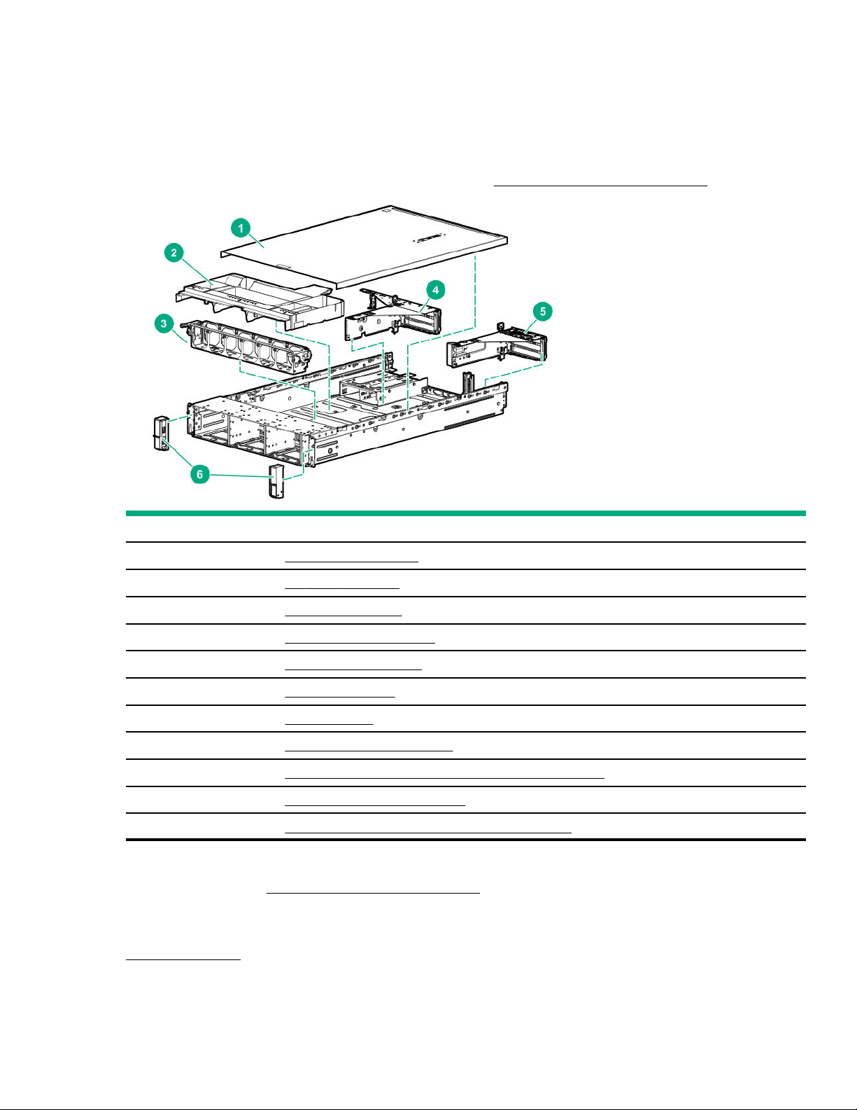
Illustrated parts catalog
Mechanical components
Hewlett Packard Enterprise continually improves and changes product parts. For complete and current supported parts
information, see the Hewlett Packard Enterprise PartSurfer website (http://www.hpe.com/info/partssurfer).
Item Description
1 Access panel spare part
2 Air bale spare part
3 Fan cage spare parts
4, 5 PCIe riser cage spare parts
6 2U bezel ear spare parts
— 2U bezel spare part
— Fan spare parts
— Mezzanine bracket spare part
— HPE Smart Storage Battery latch and retainer spare part
— Miscellaneous blank spare parts
— Rack mounting and cable management spare parts
1
Not shown
For more information, see Removal and replacement procedures.
Access panel spare part
1
1
1
1
1
1
Customer self repair: mandatory
Illustrated parts catalog
7
Page 8

Description Spare part number
Access panel with label 877954-001
Air bale spare part
Customer self repair: mandatory
Description Spare part number
Air bale 878414-001
Fan cage spare parts
Customer self repair: mandatory
Description Spare part number
Fan cage with louvers 877953-001
Louver 878409-001
PCIe riser cage spare parts
Customer self repair: mandatory
Description
Primary PCIe riser cage 877956-001
Secondary PCIe riser cage 875056-001
Secondary PCIe riser cage fastener 875984-002
Butterfly PCIe riser cage 877955-001
2U bezel ear spare parts
Customer self repair: mandatory
Description
Standard left bezel ear 878410-001
Standard right bezel ear 878411-001
2U bezel spare part
Customer self repair: mandatory
Spare part number
Spare part number
Description
2U bezel 875065-001
8 Illustrated parts catalog
Spare part number
Page 9

Fan spare parts
Customer self repair: mandatory
Description Spare part number
High-performance fan 875076-001
Mezzanine bracket spare part
Customer self repair: mandatory
Description Spare part number
Mezzanine front and rear bracket kit 878408-001
HPE Smart Storage Battery latch and retainer spare part
Customer self repair: mandatory
Description Spare part number
HPE Smart Storage Battery latch and retainer kit 878417-001
Miscellaneous blank spare parts
Customer self repair: mandatory
Description
Power supply/butterfly riser blank kit 878415-001
Optical drive blank 707300-001
Memory slot blank 812914-001
HDD bay blank kit 777301-001
SFF HDD bay blank 670033-001
Processor dust cover/blank 878418-001
Rear miscellaneous blanks kit 875067-001
Power supply blank 775423-001
Miscellaneous hardware kit 809955-001
Rack mounting and cable management spare parts
Customer self repair: mandatory
Spare part number
Description
2U Rack mounting kit 744115-001
Cable management arm 744116-001
Spare part number
Illustrated parts catalog 9
Page 10
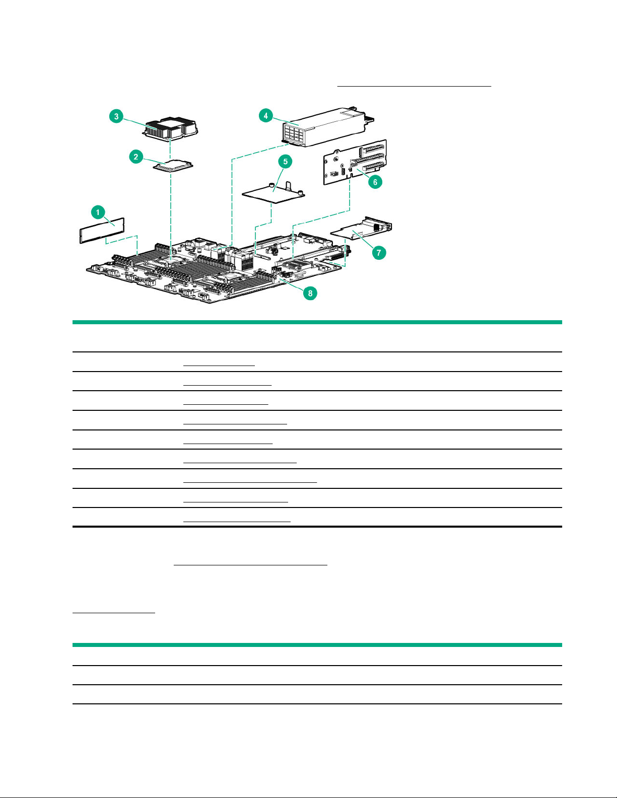
System components
Hewlett Packard Enterprise continually improves and changes product parts. For complete and current supported parts
information, see the Hewlett Packard Enterprise PartSurfer website (http://www.hpe.com/info/partssurfer).
Item
1 DIMM spare parts
2 Processor spare parts
3 Heatsink spare parts
4 Power supply spare parts
5 Controller spare parts
6 PCIe riser board spare parts
7 FlexibleLOM adapter spare parts
8 System board spare parts
— System battery spare part
1
Not shown
For more information, see Removal and replacement procedures.
DIMM spare parts
Customer self repair: mandatory
Description
1
2666 MT/s DIMMs
Description
DIMM, 8GB PC4-2666V-R, 1Gx8 850879-001
DIMM, 8GB PC4-2666V-R, 512Mx8 878490-001
10 Illustrated parts catalog
Spare part number
Table Continued
Page 11

Description Spare part number
DIMM, 16GB PC4-2666V-R, 2Rx4 850880-001
DIMM, 16GB PC4-2666V-R, 2Rx8 868846-001
DIMM, 32GB PC4-2666V-R, 2Gx4 850881-001
DIMM, 64GB PC4-2666V-L, 2Gx4 850882-001
DIMM, 128GB PC4-2666V-L, 2Gx4 850883-001
2933 MT/s DIMMs
Description Spare part number
DIMM, 8GB PC4-2933Y-R, 1Gx8 P06186-001
DIMM, 16GB PC4-2933Y-R, 2Gx4 P06187-001
DIMM, 16GB PC4-2933Y-R, 1Gx8 P06188-001
DIMM, 32GB PC4-2933Y-R, 2Gx4 P06189-001
DIMM, 64GB PC4-2933Y-L, 2Gx4 P06190-001
DIMM, 64GB PC4-2933Y-R, 4Gx4 P06192-001
DIMM, 128GB PC4-2933Y-L, 2Gx4 P06191-001
DIMM, 128GB PC4-2933Y-L, 4Gx4 P16001-001
HPE 16GB NVDIMM spare part
Customer self repair: mandatory
Description
NVDIMM 16GB 1Rx4 NN4-2666V-R 874540-001
HPE Persistent Memory module spare parts
Customer self repair: Mandatory
Description
HPE Persistent Memory module, 128 GB 844071-001
HPE Persistent Memory module, 256 GB 844072-001
HPE Persistent Memory module, 512 GB 844073-001
Spare part number
Processor spare parts
First Generation Intel Xeon Scalable Processor spare parts
Spare part number
Customer self repair: no
Illustrated parts catalog
11
Page 12

51XX processors
Description Spare part number
24-GHz Intel Xeon-G 5115 processor 878082-001
23-GHz Intel Xeon-G 5118 processor 875717-001
22-GHz Intel Xeon-G 5120 processor 875718-001
36-GHz Intel Xeon-G 5122 processor 875719-001
61XX processors
Description Spare part number
26-GHz Intel Xeon-G 6126 processor 875720-001
34-GHz Intel Xeon-G 6128 processor 875721-001
21-GHz Intel Xeon-G 6130 processor 874736-001
26-GHz Intel Xeon-G 6132 processor 875722-001
32-GHz Intel Xeon-G 6134 processor 875723-001
32-GHz Intel Xeon-G 6134M processor 878083-001
30-GHz Intel Xeon-G 6136 processor 875724-001
20-GHz Intel Xeon-G 6138 processor 874735-001
23-GHz Intel Xeon-G 6140 processor 874734-001
23-GHz Intel Xeon-G 6140M processor 878084-001
26-GHz Intel Xeon-G 6142 processor 874733-001
26-GHz Intel Xeon-G 6142M processor 878085-001
35-GHz Intel Xeon-G 6144 processor 875725-001
32-GHz Intel Xeon-G 6146 processor 875726-001
24-GHz Intel Xeon-G 6148 processor 874732-001
27-GHz Intel Xeon-G 6150 processor 874731-001
21-GHz Intel Xeon-G 6152 processor 874730-001
30-GHz Intel Xeon-G 6154 processor 875727-001
81XX processors
Description
20 GHz Intel Xeon-P 8153 processor 875728-001
36 GHz Intel Xeon-P 8156 processor 875732-001
Spare part number
30 GHz Intel Xeon-P 8158 processor 875733-001
21 GHz Intel Xeon-P 8160 processor 874729-001
21 GHz Intel Xeon-P 8160M processor 878086-001
12 Illustrated parts catalog
Table Continued
Page 13

Description Spare part number
20 GHz Intel Xeon-P 8164 processor 875729-001
27 GHz Intel Xeon-P 8168 processor 875730-001
21 GHz Intel Xeon-P 8170 processor 874728-001
21 GHz Intel Xeon-P 8170M processor 878087-001
21 GHz Intel Xeon-P 8176 processor 874727-001
21 GHz Intel Xeon-P 8176M processor 878088-001
25 GHz Intel Xeon-P 8180 processor 875731-001
25 GHz Intel Xeon-P 8180M processor 878089-001
Second-generation Intel Xeon Scalable Processor spare parts
Customer self repair: no
52XX processors
Description Spare part number
25 GHz Intel Xeon-G 5215 processor P11610-001
26 GHz Intel Xeon-G 5215L processor P11631-001
26 GHz Intel Xeon-G 5215M processor P11626-001
30 GHz Intel Xeon-G 5217 processor P11611-001
23 GHz Intel Xeon-G 5218 processor P11612-001
23 GHz Intel Xeon-G 5218B processor P12532-001
23 GHz Intel Xeon-G 5218N processor P12021-001
22 GHz Intel Xeon-G 5220 processor P11613-001
27 GHz Intel Xeon-G 5220S processor P11627-001
38 GHz Intel Xeon-G 5222 processor P11632-001
62XX processors
Description
18 GHz Intel Xeon-G 6222V processor P12019-001
27 GHz Intel Xeon-G 6226 processor P12008-001
21 GHz Intel Xeon-G 6230 processor P11614-001
23 GHz Intel Xeon-G 6230N processor P12022-001
33 GHz Intel Xeon-G 6234 processor P12009-001
Spare part number
21 GHz Intel Xeon-G 6238 processor P12010-001
21 GHz Intel Xeon-G 6238L processor P12016-001
Table Continued
Illustrated parts catalog 13
Page 14

Description Spare part number
21 GHz Intel Xeon-G 6238M processor P12014-001
26 GHz Intel Xeon-G 6240 processor P11615-001
26 GHz Intel Xeon-G 6240L processor P12015-001
26 GHz Intel Xeon-G 6240M processor P12013-001
26/28/31 GHz Intel Xeon-G 6240Y processor P11637-001
28 GHz Intel Xeon-G 6242 processor P11616-001
36 GHz Intel Xeon-G 6244 processor P11617-001
33 GHz Intel Xeon-G 6246 processor P12018-001
25 GHz Intel Xeon-G 6248 processor P11618-001
21 GHz Intel Xeon-G 6252 processor P11619-001
23 GHz Intel Xeon-G 6252N processor P12023-001
31 GHz Intel Xeon-G 6254 processor P11620-001
19 GHz Intel Xeon-G 6262V processor P12020-001
82XX processors
Description
22 GHz Intel Xeon-P 8253 processor P12011-001
38 GHz Intel Xeon-P 8256 processor P12012-001
24 GHz Intel Xeon-P 8260 processor P11621-001
24 GHz Intel Xeon-P 8260L processor P11633-001
24 GHz Intel Xeon-P 8260M processor P11628-001
23 GHz Intel Xeon-P 8260Y processor P11638-001
29 GHz Intel Xeon-P 8268 processor P11622-001
26 GHz Intel Xeon-P 8270 processor P11623-001
22 GHz Intel Xeon-P 8276 processor P11624-001
22 GHz Intel Xeon-P 8276L processor P11634-001
22 GHz Intel Xeon-P 8276M processor P11629-001
27 GHz Intel Xeon-P 8280 processor P11625-001
27 GHz Intel Xeon-P 8280L processor P11635-001
27 GHz Intel Xeon-P 8280M processor P11630-001
Spare part number
Heatsink spare parts
Customer self repair: no
14
Illustrated parts catalog
Page 15

Description Spare part number
Standard heatsink 872452-001
1U high-performance heatsink P13347-001
Power supply spare parts
Customer self repair: mandatory
Description Spare part number
800 W, Flex Slot -48VDC 754382-001
800 W, Flex Slot Titanium 754378-001
1600 W, Flex Slot Platinum 863373-001
800 W, Flex Slot DC 277V 866727-001
800 W, Flex Slot PlatinumPlus 754381-001
Power supply backplane 877948-001
Controller spare parts
Customer self repair: optional
Smart Array SAS controllers
Description
HPE Smart Array P816i-a SR Gen10 Controller 836261-001
HPE Smart Array P816i-a LH SR Gen10 Controller 871041-001
HPE Smart Array E208i-a SR Gen10 Controller 836259-001
HPE Smart Array E208i-p SR Gen10 Controller 836266-001
HPE Smart Array E208e-p SR Gen10 Controller 836267-001
HPE Smart Array P408e-p SR Gen10 Controller 836270-001
HPE Smart Array P408i-a SR Gen10 Controller 836260-001
HPE Smart Array P408i-a LH SR Gen10 Controller 871040-001
HPE Smart Array P408i-p SR Gen10 Controller 836269-001
HPE Smart Array P824i-p MR Gen10 Controller 871043-001
Fibre channel controllers
Description
HPE CN1100R 2P Converged Network Adapter 706801-001
Spare part number
Spare part number
HPE SN1100Q 16Gb 1P FC HBA 863010-001
HPE SN1100Q 16Gb 2P FC HBA 853011-001
Table Continued
Illustrated parts catalog 15
Page 16

Description Spare part number
HPE SN1200E 16Gb 1P FC HBA 870001-001
HPE SN1200E 16Gb 2P FC HBA 870002-001
HPE SN1600E 32Gb 1P FC HBA 869999-001
HPE SN1600E 32Gb 2P FC HBA 870000-001
HPE SN1600Q 32Gb 1P FC HBA 868140-001
HPE SN1600Q 32Gb 2P FC HBA 868141-001
HPE SN1610E 32Gb 1P FC HBA P14421-001
HPE SN1610E 32Gb 2P FC HBA P14422-001
HPE SN1610Q 32Gb 1P FC HBA P14419-001
HPE SN1610Q 32Gb 2P FC HBA P14420-001
HPE StoreFabric CN1100R-T 10Gb CNA 827605-001
HPE StoreFabric CN1200E 10Gb CNA 767078-001
HPE StoreFabric CN1200E-T 10Gb CNA 827607-001
HPE StoreFabric CN1200R 10GBASE-T CNA 872527-001
HPE StoreFabric CN1300R 10/25Gb CNA 872526-001
Network controllers
Description
HPE Ethernet 10/25Gb 2P 631FLR-SFP28 adapter 840133-001
HPE FlexFabric 10Gb 4P 536FLR-T adapter 768082-001
HPE Ethernet 10Gb 2P 530SFP+ adapter 656244-001
HPE FlexFabric 10Gb 2P 534FLR-SFP+ adapter 701531-001
HPE Ethernet 10/25Gb 2P 631SFP28 adapter 840130-001
HPE Ethernet 10Gb 2P 535T adapter 815669-001
HPE Ethernet 10Gb 2P 535FLR-T adapter 854177-001
HPE Ethernet 1Gb 4P 331FLR adapter 789897-001
HPE FlexFabric 10Gb 2P 533FLR-T adapter 701534-001
HPE Ethernet 10Gb 2P 524SFP+ adapter P11585-001
HPE Ethernet 10/25Gb 2P 661SFP28 adapter 879666-001
HPE Ethernet 10Gb 2-port 562SFP+ adapter 790316-001
HPE Ethernet 10Gb 2P 562T adapter 840137-001
HPE Ethernet 10Gb 2-port 562FLR-SFP+ adapter 790317-001
Spare part number
HPE Ethernet 10Gb 2P 562FLR-T adapter 840138-001
HPE Ethernet 1Gb 4-port 366FLR adapter 669280-001
16 Illustrated parts catalog
Table Continued
Page 17

Description Spare part number
HPE Ethernet 1Gb 4-port 366T adapter 816551-001
HPE Ethernet 10/25Gb 2P 640FLR-SFP28 adapter 840139-001
HPE Ethernet 10/25Gb 2P 640SFP28 adapter 840140-001
HPE Ethernet 10Gb 2P 548SFP+ adapter P11338-B21
HPE Ethernet 1Gb 4-port 331T adapter 649871-001
HPE Ethernet 10/25Gb 2P 621SFP28 adapter 869570-001
HPE Ethernet 10Gb 2P 522FLR-T CNA 869571-001
HPE Ethernet 4x25Gb 1P 620QSFP28 adapter 840134-001
HPE Ethernet 10/25Gb 2P 622FLR-SFP28 CNA 869572-001
HPE Ethernet 10Gb 2P 521T adapter 869573-001
HPE Ethernet 100Gb 1P 842QSFP28 adapter 877697-001
HPE Ethernet 10Gb 2P 530T adapter 657128-001
HPE Ethernet 1Gb 2P 361T adapter 656241-001
HPE Ethernet 1Gb 2P 332T adapter 616012-001
HPE Ethernet 10Gb 2P 524SFP+ Adapter P11585-001
HPE Ethernet 10Gb 2P 548SFP+ Adapter P12531-001
InfiniBand adapters
Description
HPE IB FDR/EN 40Gb 2P 544+FLR-QSFP adapter 764737-001
HPE IB FDR/EN 40Gb 2P 544+QSFP adapter 764736-001
HPE IB EDR 100Gb 1P 841QSFP28 adapter 878578-001
HPE IB EDR/EN 100Gb 2P 841QSFP28 adapter 878579-001
HPE IB FDR/EN 40/50Gb 547FLR 2QSFP adapter 879667-001
HPE IB EDR/EN 100Gb 1P 840QSFP28 adapter 828107-001
HPE IB EDR/EN 100Gb 2P 840QSFP28 adapter 828108-001
HPE 100Gb 1P OP101 QSFP28 x16 OPA adapter 841703-001
HPE 100Gb 1P OP101 QSFP28 x8 OPA adapter 841702-001
HPE InfiniBand HDR/Ethernet 200Gb 1-port 940 QSFP 56
x16 Adapter
HPE InfiniBand HDR PCIe G3 Auxiliary card with 350 mm
cable kit
Spare part number
P08354-001
P10331-001
HPE InfiniBand HDR100/Ethernet 1-port 940 QSFP 56 x16
Adapter
HPE InfiniBand HDR100/Ethernet 100Gb 2-port 940 QSFP
56 x16 Adapter
P08356-001
P08355-001
Illustrated parts catalog 17
Page 18

PCIe riser board spare parts
Customer self repair: optional
Description Spare part number
3S 2x8 x16 PCIe M.2 riser 877946-001
3S 2x8 x16 PCIe riser 875058-001
x16 x16 PCIe S2/3 riser 875060-001
x162P Slimline tertiary riser 875062-001
3 x8/x1 Slimline riser 875086-001
4-S x8 Slimline riser 875087-001
x8-x8 riser 877947-001
3 x8 Slimline riser 877950-001
FlexibleLOM adapter spare parts
Customer self repair: mandatory
Description Spare part number
HPE Infiniband FDR/EN 40Gb 2-port, 544+ FLR-QSFP Adapter 764737-001
HPE Infiniband FDR/EN 40Gb 2-port, 544+ QSFP Adapter 764736-001
HPE Infiniband EDR 100Gb 1P 841QSFP28 Adapter 878578-001
HPE Infiniband EDR/EN 100Gb 1P 840QSFP28 Adapter 828107-001
HPE Infiniband EDR/EN 100Gb 2P 840QSFP28 Adapter 828108-001
HPE 100Gb 1P OP101 QSFP28 x16 OPA Adapter 841703-001
HPE 100Gb 1P OP101 QSFP28 x8 OPA Adapter 841702-001
System board spare parts
Customer self repair: optional
Description
System board P11741-001
System battery spare part
Customer self repair: mandatory
Spare part number
Description
System battery 319603-001
18 Illustrated parts catalog
Spare part number
Page 19
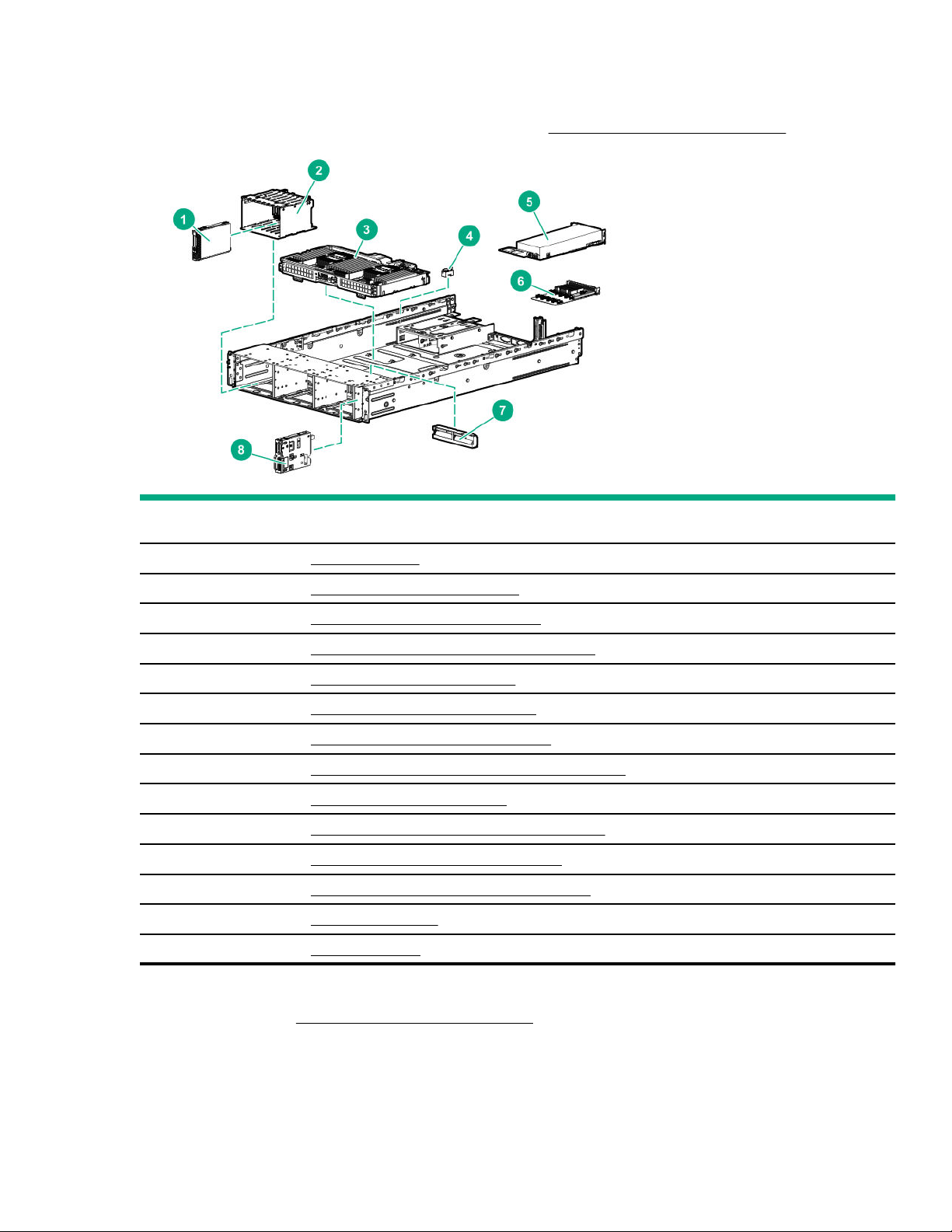
Server options
Hewlett Packard Enterprise continually improves and changes product parts. For complete and current supported parts
information, see the Hewlett Packard Enterprise PartSurfer website (http://www.hpe.com/info/partssurfer).
Item
Description
1 Drive spare parts
2 Drive cage backplane spare parts
3 Processor mezzanine tray spare part
4 Chassis Intrusion Detection Switch spare part
5 Accelerator and GPU spare parts
6 12G SAS expander board spare part
7 HPE Smart Storage Battery spare part
8 Power module/System Insight Display spare parts
— Universal media bay spare part
— CPU Mezzanine UPI performance kit spare part
— 4-port NVMe mezzanine card spare part
— HPE Trusted Platform Module 2.0 spare part
— microSD spare parts
— Cable spare parts
1
1
1
1
1
1
1
Not shown
For more information, see Removal and replacement procedures.
Drive spare parts
Illustrated parts catalog
19
Page 20

Hot-plug drive spare parts
Customer self repair: mandatory
Description Spare part
300GB SAS 10K SFF SC DS HDD 872735-001
300GB SAS 15K SFF SC DS HDD 870792-001
600GB SAS 10K SFF SC DS HDD 872736-001
600GB SAS 15K SFF SC DS HDD 870794-001
600GB SAS 15K SFF SC 512e DS HDD 870797-001
900GB SAS 10K SFF SC HDD 785411-001
900GB SAS 15K SFF SC DS HDD 870795-001
900GB SAS 15K SFF SC 512e DS HDD 870798-001
1TB SAS 72K SFF SC DS HDD 832984-001
1TB SAS 72K SFF SC 512e DS HDD 765872-001
1TB SATA 72K SFF SC 512e DS HDD 765868-001
1TB SATA 72K SFF SC DS HDD 656108-001
number
12TB SAS 10K SFF SC DS HDD 872737-001
18TB SAS 10K SFF SC 512e DS HDD 872738-001
2TB SAS 72K SFF SC 512e DS HDD 765873-001
2TB SATA 72K SFF SC 512e DS HDD 765869-001
Solid-state NVMe spare parts
Customer self repair: mandatory
Description
375 GB NVMe x4 WI SFF SCN DS SSD P02559-001
400 GB NVMe x4 MU SFF SCN DS SSD 875874-001
400 GB NVMe x4 MU SFF SCN SSD 765063-001
400 GB NVMe x4 RI SFF SCN SSD 765067-001
400 GB NVMe x4 WI SFF SC SSD 765059-001
480 GB NVMe x4 RI SFF SCN DS SSD 875871-001
750 GB NVMe x4 WI SFF SCN DS SSD P06979-001
800 GB NVMe x4 MU SFF SCN DS SSD 875875-001
Spare part number
800 GB NVMe x4 MU SFF SCN SSD 765064-001
800 GB NVMe x4 WI SFF SCN SSD 765060-001
800 GB NVMe x4 MU SFF SCN DS SSD P10648-001
20 Illustrated parts catalog
Table Continued
Page 21

Description Spare part number
800 GB NVMe x4 MU SFF SCN DS SSD P13826-001
960 GB NVMe x4 RI SFF SCN DS SSD P10645-001
960 GB NVMe x4 RI SFF SCN DS SSD P10652-001
960 GB NVMe x4 RI SFF SCN DS SSD P13831-001
12 TB NVMe x4 RI SFF SCN SSD 765068-001
16 TB NVMe x4 MU SFF SCN DS SSD 875876-001
16 TB NVMe x4 MU SFF SCN DS SSD P10649-001
16 TB NVMe x4 MU SFF SCN DS SSD P13835-001
16 TB NVMe x4 MU SFF SCN SSD 765065-001
16 TB NVMe x4 MU SFF SCN DS SSD P13827-001
16 TB NVMe x4 WI SFF SCN SSD 765061-001
192 TB NVMe x4 RI SFF SCN DS SSD 875873-001
192 TB NVMe x4 RI SFF SCN DS SSD P10646-001
192 TB NVMe x4 RI SFF SCN DS SSD P10466-001
192 TB NVMe x4 RI SFF SCN DS SSD P10653-001
192 TB NVMe x4 RI SFF SCN DS SSD P13832-001
2 TB NVMe x4 MU SFF SCN SSD 765066-001
2 TB NVMe x4 RI SFF SCN DS SSD P13838-001
2 TB NVMe x4 WI SFF SCN SSD 765062-001
32 TB NVMe x4 MU SFF SCN DS SSD 880246-001
32 TB NVMe x4 MU SFF SCN DS SSD P10471-001
32 TB NVMe x4 MU SFF SCN DS SSD P10650-001
32 TB NVMe x4 MU SFF SCN DS SSD P13836-001
32 TB NVMe x4 MU SFF SCN DS SSD P13828-001
384 TB NVMe x4 RI SFF SCN DS SSD P10647-001
384 TB NVMe x4 RI SFF SCN DS SSD P10467-001
384 TB NVMe x4 RI SFF SCN DS SSD P10654-001
384 TB NVMe x4 RI SFF SCN DS SSD P13833-001
4 TB NVMe x4 RI SFF SCN DS SSD 880243-001
4 TB NVMe x4 RI SFF SCN DS SSD P13839-001
64 TB NVMe x4 MU SFF SCN DS SSD P10472-001
64 TB NVMe x4 MU SFF SCN DS SSD P10651-001
64 TB NVMe x4 MU SFF SCN DS SSD P13837-001
Table Continued
Illustrated parts catalog 21
Page 22

Description Spare part number
64 TB NVMe x4 MU SFF SCN DS SSD P13829-001
768 TB NVMe x4 RI SFF SCN DS SSD P10468-001
768 TB NVMe x4 RI SFF SCN DS SSD P10655-001
768 TB NVMe x4 RI SFF SCN DS SSD P13834-001
1536 TB NVMe x4 RI SFF SCN DS SSD P10656-001
Solid-state drive M.2 spare parts
Customer self repair: mandatory
Description Spare part number
120GB 6G SATA RI M.22280 SSD 781565-001
120GB SATA M.2 single drive module enablement kit 797907-001
150GB SATA RI M.22280 DS SSD 875835-001
240GB SATA MU M.22280 DS SSD 875850-001
340GB SATA RI M.22280 SSD 781566-001
340GB SATA M.2 single drive module enablement kit 835801-001
340GB SATA M.2 dual drive module enablement kit 835802-001
480GB SATA MU M.22280 DS SSD 875851-001
480GB SATA RI M.22280 DS SSD 875836-001
480GB SATA RI M.22280 DS SSD 875855-001
960GB SATA MU M.22280 DS SSD 875852-001
960GB SATA RI M.22280 DS SSD 875856-001
192TB SATA MU M.22280 DS SSD 875853-001
192TB SATA RI M.22280 DS SSD 875854-001
M.2 ML/DL SATA riser assembly 882359-001
Solid-state drive SAS spare parts
Customer self repair: mandatory
Description
400 GB SAS 12G MU SFF SC DS SSD 872505-001
400 GB SAS 12G MU SFF SC DS SSD 873566-001
400 GB SAS 12G WI SFF SC DS SSD 873563-001
Spare part number
480 GB SAS RI SFF SC DS SSD 875681-001
400 GB SAS MU SFF SC DS SSD P06576-001
400 GB SAS MU SFF SC DS SSD P09922-001
22 Illustrated parts catalog
Table Continued
Page 23

Description Spare part number
400 GB SAS WI SFF SC DS SSD P06600-001
400 GB SAS WI SFF SC DS SSD P09947-001
800 GB SAS 12G MU SFF SC DS SSD 872506-001
800 GB SAS 12G MU SFF SC DS SSD 873569-001
800 GB SAS 12G WI SFF SC DS SSD 873564-001
800 GB SAS MU SFF SC DS SSD P06577-001
800 GB SAS MU SFF SC DS SSD P09923-001
800 GB SAS MU SFF SC SSD P20838-001
800 GB SAS WI SFF SC DS SSD P06602-001
800 GB SAS WI SFF SC DS SSD P09948-001
960 GB SAS 12G RI SFF SC DS SSD 872432-001
960 GB SAS MU SFF SC VS DS SSD P10604-001
960 GB SAS RI SFF SC DS SSD 875682-001
960 GB SAS RI SFF SC DS SSD P08608-001
960 GB SAS RI SFF SC DS SSD P06596-001
960 GB SAS RI SFF SC SSD P20833-001
960 GB SAS RI SFF SC VS DS SSD P10637-001
16 TB SAS 12G MU SFF SC DS SSD 872509-001
16 TB SAS 12G MU SFF SC DS SSD 873570-001
16 TB SAS MU SFF SC SSD P20839-001
16 TB SAS 12G WI SFF SC DS SSD 873565-001
16 TB SAS WI SFF SC DS SSD P09949-001
192 TB SAS 12G RI SFF SC DS SSD 872433-001
192 TB SAS MU SFF SC VS DS SSD P10607-001
192 TB SAS RI SFF SC DS SSD 875684-001
192 TB SAS RI SFF SC DS SSD P08609-001
192 TB SAS RI SFF SC DS SSD P06597-001
192 TB SAS RI SFF SC SSD P20834-001
192 TB SAS RI SFF SC VS DS SSD P10638-001
32 TB SAS 12G MU SFF SC DS SSD 872511-001
32 TB SAS 12G MU SFF SC DS SSD 873571-001
32 TB SAS MU SFF SC DS SSD P06582-001
32 TB SAS MU SFF SC DS SSD P09925-001
Table Continued
Illustrated parts catalog 23
Page 24

Description Spare part number
32 TB SAS MU SFF SC SSD P20840-001
32 TB SAS WI SFF SC DS SSD P06605-001
384 TB SAS 12G RI SFF SC DS SSD 872434-001
384 TB SAS MU SFF SC VS DS SSD P10610-001
384 TB SAS RI SFF SC DS SSD 875686-001
384 TB SAS RI SFF SC DS SSD P08610-001
384 TB SAS RI SFF SC DS SSD P06598-001
384 TB SAS RI SFF SC SSD P20835-001
384 TB SAS RI SFF SC VS DS SSD P10639-001
64 TB SAS MU SFF SC DS SSD P06583-001
64 TB SAS MU SFF SC DS SSD P09926-001
64 TB SAS MU SFF SC SSD P20841-001
768 TB SAS 12G RI SFF SC DS SSD 870460-001
768 TB SAS RI SFF SC DS SSD P08611-001
768 TB SAS RI SFF SC DS SSD P06599-001
768 TB SAS RI SFF SC SSD P20836-001
768 TB SAS RI SFF SC VS DS SSD P10640-001
153 TB SAS 12G RI SFF SC DS SSD 870462-001
153 TB SAS RI SFF SC DS SSD P08612-001
153 TB SAS RI SFF SC SSD P20837-001
Solid-state drive SATA spare parts
Customer self repair: mandatory
Description
120 GB SATA MU SFF SC SSD 817096-001
150 GB SATA 6G RI SFF SC DS SSD 869575-001
200 GB SATA WI SFF SC SSD 805385-001
240 GB SATA 6G RI SFF SC DS SSD 868924-001
240 GB SATA 6G RI SFF SC DS SSD 869576-001
240 GB SATA MU SFF SC DS SSD 882219-001
240 GB SATA MU SFF SC DS SSD 875703-001
Spare part number
240 GB SATA MU SFF SC SSD 817101-001
240 GB SATA RI SFF SC DS SSD 878844-001
240 GB SATA RI SFF SC DS SSD 875652-001
24 Illustrated parts catalog
Table Continued
Page 25

Description Spare part number
240 GB SATA RI SFF SC DS SSD P05319-001
240 GB SATA RI SFF SC DS SSD P08565-001
240 GB SATA RI SFF SC MV SSD P18481-001
400 GB SATA 6G WI SFF SC DS SSD 872512-001
400 GB SATA WI SFF SC SSD 805387-001
480 GB SATA 6G MU SFF SC DS SSD 872518-001
480 GB SATA 6G RI SFF SC DS SSD 868926-001
480 GB SATA 6G RI SFF SC DS SSD 869577-001
480 GB SATA MU SFF SC DS SSD 879013-001
480 GB SATA MU SFF SC DS SSD 875863-001
480 GB SATA MU SFF SC DS SSD P07923-B21
480 GB SATA MU SFF SC SSD 817106-001
480 GB SATA MU SFF SC DS SSD P09907-001
480 GB SATA MU SFF SC DS SSD P08620-001
480 GB SATA MU SFF SC DS SSD P13808-001
480 GB SATA MU SFF SC MV SSD P18477-001
480 GB SATA RI SFF SC DS SSD 878846-001
480 GB SATA RI SFF SC DS SSD 875655-001
480 GB SATA RI SFF SC DS SSD P05320-001
480 GB SATA RI SFF SC DS SSD P06571-001
480 GB SATA RI SFF SC DS SSD P08567-001
480 GB SATA RI SFF SC MV SSD P18482-001
800 GB SATA 6G WI SFF SC DS SSD 872514-001
800 GB SATA WI SFF SC SSD 805389-001
960 GB SATA 6G MU SFF SC DS SSD 872520-001
960 GB SATA 6G RI SFF SC DS SSD 868928-001
960 GB SATA 6G RI SFF SC DS SSD 869580-001
960 GB SATA MU SFF SC DS SSD 879016-001
960 GB SATA MU SFF SC DS SSD 875865-001
960 GB SATA MU SFF SC DS SSD P08692-001
960 GB SATA MU SFF SC DS SSD P09909-001
960 GB SATA MU SFF SC DS SSD P08622-001
960 GB SATA MU SFF SC DS SSD P13809-001
Table Continued
Illustrated parts catalog 25
Page 26

Description Spare part number
960 GB SATA MU SFF SC MV SSD P18478-001
960 GB SATA RI SFF SC DS SSD 878849-001
960 GB SATA RI SFF SC DS SSD 875656-001
960 GB SATA RI SFF SC DS SSD P05321-001
960 GB SATA RI SFF SC DS SSD P06572-001
960 GB SATA RI SFF SC DS SSD P08569-001
960 GB SATA RI SFF SC MV SSD P18483-001
12 TB SATA WI SFF SC SSD 805391-001
16 TB SATA 6G RI SFF SC DS SSD 869581-001
16 TB SATA 6G WI SFF SC DS SSD 872516-001
192 TB SATA 6G MU SFF SC DS SSD 872522-001
192 TB SATA 6G RI SFF SC DS SSD 868930-001
192 TB SATA MU SFF SC DS SSD 879019-001
192 TB SATA MU SFF SC DS SSD 875867-001
192 TB SATA MU SFF SC DS SSD P08694-001
192 TB SATA MU SFF SC SSD 817116-001
192 TB SATA MU SFF SC DS SSD P09912-001
192 TB SATA MU SFF SC DS SSD P08625-001
192 TB SATA MU SFF SC DS SSD P13810-001
192 TB SATA MU SFF SC MV SSD P18479-001
192 TB SATA RI SFF SC DS SSD 878852-001
192 TB SATA RI SFF SC DS SSD 875657-001
192 TB SATA RI SFF SC DS SSD P05322-001
192 TB SATA RI SFF SC DS SSD P06573-001
192 TB SATA RI SFF SC DS SSD P08572-001
192 TB SATA RI SFF SC MV SSD P18484-001
384 TB SATA 6G RI SFF SC DS SSD 868932-001
384 TB SATA MU SFF SC DS SSD P02562-001
384 TB SATA MU SFF SC DS SSD P08632-001
384 TB SATA MU SFF SC DS SSD P13811-001
384 TB SATA MU SFF SC DS SSD P22588-001
384 TB SATA MU SFF SC MV SSD P18480-001
384 TB SATA RI SFF SC DS SSD 878855-001
26 Illustrated parts catalog
Table Continued
Page 27

Description Spare part number
384 TB SATA RI SFF SC DS SSD P05323-001
384 TB SATA RI SFF SC DS SSD P06574-001
384 TB SATA RI SFF SC DS SSD P08575-001
384 TB SATA RI SFF SC MV SSD P18485-001
768 TB SATA RI SFF SC MV SSD P18486-001
Drive cage backplane spare parts
Customer self repair: optional
Description Spare part number
Eight-bay SFF HDD drive cage assembly, 12 Gbs 780971-001
Eight-bay SFF HDD drive cage backplane, 12 Gbs 777279-001
Two-bay SFF SAS/SATA backplane 875064-001
Two-bay SFF NVMe SSD/Six-bay SFF HDD drive backplane
Eight-bay SFF NVMe drive backplane 872971-001
Chassis Intrusion Detection Switch spare part
Customer self repair: mandatory
Description
Chassis Intrusion Detection Switch 878412-001
Accelerator and GPU spare parts
Customer self repair: optional
GPU
Description
HPE NVIDIA Quadro P2000 GPU 871969-001
HPE NVIDIA Tesla T416 GB Module P09571-001
874933-001
Spare part number
Spare part number
HPE NVIDIA Quadro P2200 GPU Module P16021-001
PCIe accelerators
Description
HPE 750GB PCIe x4 WI HH DS Card P03580-001
HPE 375GB PCIe x4 WI HH DS Spl Card 882007-001
Spare part number
Table Continued
Illustrated parts catalog 27
Page 28

Description Spare part number
HPE 800GB PCIe x4 WI HH Card 804566-001
HPE 800GB PCIe x4 MU HH Card 804568-001
HPE 16TB PCIe x4 WI HH Card 804567-001
HPE 16TB PCIe x4 MU HH Card 804569-001
HPE 16TB PCIe x8 MU HH DS Card 879772-001
HPE 16TB NVMe x8 MU HH DS Card P10670-001
HPE 20TB PCIe x4 MU HH Card 804570-001
HPE 32TB PCIe x8 MU HH DS Card 879773-001
HPE 32TB NVMe x8 MU HH DS Card P10671-001
HPE 4TB PCIe x4 RI HH DS Card 880418-001
HPE 64TB PCIe x8 MU HH DS Card 879774-001
HPE 64TB NVMe x8 MU HH DS Card P10672-001
HPE 8TB PCIe x4 RI HH DS Card 880419-001
12G SAS expander board spare part
Customer self repair: optional
Description
12G SAS expander board 876907-001
HPE Smart Storage Battery spare part
Customer self repair: mandatory
Description
HPE Smart Storage Battery 878643-001
HPE Smart Storage Hybrid Capacitor spare part
Customer self repair: mandatory
Description
HPE Smart Storage Hybrid Capacitor, 145mm cable P07473-001
Power module/System Insight Display spare parts
Spare part number
Spare part number
Spare part number
Customer self repair: mandatory
Description
Power module with Systems Insight Display 878734-001
Power module without Systems Insight Display 878733-001
28 Illustrated parts catalog
Spare part number
Page 29

Universal media bay spare part
Customer self repair: mandatory
Description Spare part number
Universal media bay assembly 877958-001
CPU Mezzanine UPI performance kit spare part
Customer self repair: optional
Description Spare part number
CPU Mezzanine UPI performance kit board 877952-001
Processor mezzanine tray spare part
Customer self repair: optional
Description Spare part number
Processor mezzanine tray P11742-001
4-port NVMe mezzanine card spare part
Customer self repair: optional
Description
4-port NVMe mezzanine card 877951-001
HPE Trusted Platform Module 2.0 spare part
Customer self repair: no
Description
HPE Trusted Platform Module 20 Gen 10 kit, TAA 872159-001
microSD spare parts
Customer self repair: mandatory
Description
HPE 32GB microSD Flash Memory card 704502-001
HPE 8GB microSD Flash Memory card 738576-001
Spare part number
Spare part number
Spare part number
HPE 8GB microSD Flash USB drive 743503-001
HPE 8GB dual microSD Flash USB drive 870891-001
HPE 32GB microSD RAID 1 USB boot drive P23103-001
Illustrated parts catalog 29
Page 30

Cable spare parts
Customer self repair: mandatory
Description Spare part number
SATA data cable assembly 877957-001
Flex bay cable assembly 877958-001
Bay 38SFF power cable 877960-001
2SFF cable kit 877963-001
MiniSAS cable kit (8SFF) 877980-001
MiniSAS cable kit (SAS Expander) 877981-001
NVMe bay 2–Colossus LFT/RHT cable kit 877982-001
NVMe cable kit 877983-001
Controller backup power cable (short) 878645-001
Controller backup power cable (long) 878646-001
JMP CRD C13/C14 India 20M BLK cable P10794-001
30 Illustrated parts catalog
Page 31

Customer self repair
Hewlett Packard Enterprise products are designed with many Customer Self Repair (CSR) parts to minimize repair time and
allow for greater flexibility in performing defective parts replacement. If during the diagnosis period Hewlett Packard
Enterprise (or Hewlett Packard Enterprise service providers or service partners) identifies that the repair can be accomplished
by the use of a CSR part, Hewlett Packard Enterprise will ship that part directly to you for replacement. There are two
categories of CSR parts:
• Mandatory—Parts for which customer self repair is mandatory. If you request Hewlett Packard Enterprise to replace these
parts, you will be charged for the travel and labor costs of this service.
• Optional—Parts for which customer self repair is optional. These parts are also designed for customer self repair. If,
however, you require that Hewlett Packard Enterprise replace them for you, there may or may not be additional charges,
depending on the type of warranty service designated for your product.
NOTE: Some Hewlett Packard Enterprise parts are not designed for customer self repair. In order to satisfy the customer
warranty, Hewlett Packard Enterprise requires that an authorized service provider replace the part. These parts are identified
as "No" in the Illustrated Parts Catalog.
Based on availability and where geography permits, CSR parts will be shipped for next business day delivery. Same day or fourhour delivery may be oered at an additional charge where geography permits. If assistance is required, you can call the
Hewlett Packard Enterprise Support Center and a technician will help you over the telephone. Hewlett Packard Enterprise
specifies in the materials shipped with a replacement CSR part whether a defective part must be returned to Hewlett Packard
Enterprise. In cases where it is required to return the defective part to Hewlett Packard Enterprise, you must ship the defective
part back to Hewlett Packard Enterprise within a defined period of time, normally five (5) business days. The defective part
must be returned with the associated documentation in the provided shipping material. Failure to return the defective part
may result in Hewlett Packard Enterprise billing you for the replacement. With a customer self repair, Hewlett Packard
Enterprise will pay all shipping and part return costs and determine the courier/carrier to be used.
For more information about the Hewlett Packard Enterprise CSR program, contact your local service provider. For the North
American program, go to the Hewlett Packard Enterprise CSR website.
Parts only warranty service
Your Hewlett Packard Enterprise Limited Warranty may include a parts only warranty service. Under the terms of parts only
warranty service, Hewlett Packard Enterprise will provide replacement parts free of charge.
For parts only warranty service, CSR part replacement is mandatory. If you request Hewlett Packard Enterprise to replace
these parts, you will be charged for the travel and labor costs of this service.
Réparation par le client (CSR)
Les produits Hewlett Packard Enterprise comportent de nombreuses pièces CSR (Customer Self Repair = réparation par le
client) afin de minimiser les délais de réparation et faciliter le remplacement des pièces défectueuses. Si pendant la période de
diagnostic, Hewlett Packard Enterprise (ou ses partenaires ou mainteneurs agréés) détermine que la réparation peut être
eectuée à l'aide d'une pièce CSR, Hewlett Packard Enterprise vous l'envoie directement. Il existe deux catégories de pièces
CSR :
• Obligatoire—Pièces pour lesquelles la réparation par le client est obligatoire. Si vous demandez à Hewlett Packard
Enterprise de remplacer ces pièces, les coûts de déplacement et main d'œuvre du service vous seront facturés.
• Facultatif—Pièces pour lesquelles la réparation par le client est facultative. Ces pièces sont également conçues pour
permettre au client
remplacer ces pièces, l'intervention peut ou non vous être facturée, selon le type de garantie applicable à votre produit.
d'eectuer lui-même la réparation. Toutefois, si vous demandez à Hewlett Packard Enterprise de
Customer self repair
31
Page 32

REMARQUE: Certaines pièces Hewlett Packard Enterprise ne sont pas conçues pour permettre au client d'eectuer lui-même
la réparation. Pour que la garantie puisse s'appliquer, Hewlett Packard Enterprise exige que le remplacement de la pièce soit
eectué par un Mainteneur Agréé. Ces pièces sont identifiées par la mention "Non" dans le Catalogue illustré.
Les pièces CSR sont livrées le jour ouvré suivant, dans la limite des stocks disponibles et selon votre situation géographique. Si
votre situation géographique le permet et que vous demandez une livraison le jour même ou dans les 4 heures, celle-ci vous
sera facturée. Pour toute assistance, appelez le Centre d’assistance Hewlett Packard Enterprise pour qu’un technicien vous
aide au téléphone Dans les documents envoyés avec la pièce de rechange CSR, Hewlett Packard Enterprise précise s'il est
nécessaire de lui retourner la pièce défectueuse. Si c'est le cas, vous devez le faire dans le délai indiqué, généralement cinq (5)
jours ouvrés. La pièce et sa documentation doivent être retournées dans l'emballage fourni. Si vous ne retournez pas la pièce
défectueuse, Hewlett Packard Enterprise se réserve le droit de vous facturer les coûts de remplacement. Dans le cas d'une
pièce CSR, Hewlett Packard Enterprise supporte l'ensemble des frais d'expédition et de retour, et détermine la société de
courses ou le transporteur à utiliser.
Pour plus d'informations sur le programme CSR de Hewlett Packard Enterprise, contactez votre Mainteneur Agrée local. Pour
plus d'informations sur ce programme en Amérique du Nord, consultez le site
Service de garantie "pièces seules"
Votre garantie limitée Hewlett Packard Enterprise peut inclure un service de garantie "pièces seules". Dans ce cas, les pièces de
rechange fournies par Hewlett Packard Enterprise ne sont pas facturées.
Dans le cadre de ce service, la réparation des pièces CSR par le client est obligatoire. Si vous demandez à Hewlett Packard
Enterprise de remplacer ces pièces, les coûts de déplacement et main d'œuvre du service vous seront facturés.
Riparazione da parte del cliente
Web Hewlett Packard Enterprise.
Per abbreviare i tempi di riparazione e garantire una maggiore flessibilità nella sostituzione di parti difettose, i prodotti Hewlett
Packard Enterprise sono realizzati con numerosi componenti che possono essere riparati direttamente dal cliente (CSR,
Customer Self Repair). Se in fase di diagnostica Hewlett Packard Enterprise (o un centro di servizi o di assistenza Hewlett
Packard Enterprise) identifica il guasto come riparabile mediante un ricambio CSR, Hewlett Packard Enterprise lo spedirà
direttamente al cliente per la sostituzione. Vi sono due categorie di parti CSR:
• Obbligatorie—Parti che devono essere necessariamente riparate dal cliente. Se il cliente ne
Hewlett Packard Enterprise, deve sostenere le spese di spedizione e di manodopera per il servizio.
• Opzionali—Parti la cui riparazione da parte del cliente è facoltativa. Si tratta comunque di componenti progettati per
questo scopo. Se tuttavia il cliente ne richiede la sostituzione ad Hewlett Packard Enterprise, potrebbe dover sostenere
spese addizionali a seconda del tipo di garanzia previsto per il prodotto.
NOTA: alcuni componenti Hewlett Packard Enterprise non sono progettati per la riparazione da parte del cliente. Per rispettare
la garanzia, Hewlett Packard Enterprise richiede che queste parti siano sostituite da un centro di assistenza autorizzato. Tali
parti sono identificate da un "No" nel Catalogo illustrato dei componenti.
In base alla disponibilità e alla località geografica, le parti CSR vengono spedite con consegna entro il giorno lavorativo
seguente. La consegna nel giorno stesso o entro quattro ore è
di necessità si può richiedere l'assistenza telefonica di un addetto del centro di supporto tecnico Hewlett Packard Enterprise.
Nel materiale fornito con una parte di ricambio CSR, Hewlett Packard Enterprise specifica se il cliente deve restituire dei
component. Qualora sia richiesta la resa ad Hewlett Packard Enterprise del componente difettoso, lo si deve spedire ad Hewlett
Packard Enterprise entro un determinato periodo di tempo, generalmente cinque (5) giorni lavorativi. Il componente difettoso
deve essere restituito con la documentazione associata nell'imballo di spedizione fornito. La mancata restituzione del
componente può comportare la fatturazione del ricambio da parte di Hewlett Packard Enterprise. Nel caso di riparazione da
parte del cliente, Hewlett Packard Enterprise sostiene tutte le spese di spedizione e resa e sceglie il corriere/vettore da
utilizzare.
oerta con un supplemento di costo solo in alcune zone. In caso
aida la riparazione ad
Per ulteriori informazioni sul programma CSR di Hewlett Packard Enterprise, contattare il centro di assistenza di zona. Per il
programma in Nord America fare riferimento al sito Web.
32
Customer self repair
Page 33

Servizio di garanzia per i soli componenti
La garanzia limitata Hewlett Packard Enterprise può includere un servizio di garanzia per i soli componenti. Nei termini di
garanzia del servizio per i soli componenti, Hewlett Packard Enterprise fornirà gratuitamente le parti di ricambio.
Per il servizio di garanzia per i soli componenti è obbligatoria la formula CSR che prevede la riparazione da parte del cliente. Se
il cliente invece richiede la sostituzione ad Hewlett Packard Enterprise dovrà sostenere le spese di spedizione e di manodopera
per il servizio.
Customer Self Repair
Hewlett Packard Enterprise Produkte enthalten viele CSR-Teile (Customer Self Repair), um Reparaturzeiten zu minimieren und
höhere Flexibilität beim Austausch defekter Bauteile zu ermöglichen. Wenn Hewlett Packard Enterprise (oder ein Hewlett
Packard Enterprise Servicepartner) bei der Diagnose feststellt, dass das Produkt mithilfe eines CSR-Teils repariert werden
kann, sendet Ihnen Hewlett Packard Enterprise dieses Bauteil zum Austausch direkt zu. CSR-Teile werden in zwei Kategorien
unterteilt:
• Zwingend—Teile, für die das Customer Self Repair-Verfahren zwingend vorgegeben ist. Wenn Sie den Austausch dieser
Teile von Hewlett Packard Enterprise vornehmen lassen, werden Ihnen die Anfahrt- und Arbeitskosten für diesen Service
berechnet.
• Optional—Teile, für die das Customer Self Repair-Verfahren optional ist. Diese Teile sind auch für Customer Self Repair
ausgelegt. Wenn Sie jedoch den Austausch dieser Teile von Hewlett Packard Enterprise vornehmen lassen möchten,
können bei diesem Service je nach den für Ihr Produkt vorgesehenen Garantiebedingungen zusätzliche Kosten anfallen.
HINWEIS: Einige Hewlett Packard Enterprise Teile sind nicht für Customer Self Repair ausgelegt. Um den Garantieanspruch
des Kunden zu erfüllen, muss das Teil von einem Hewlett Packard Enterprise Servicepartner ersetzt werden. Im illustrierten
Teilekatalog sind diese Teile mit „No“ bzw. „Nein“ gekennzeichnet.
CSR-Teile werden abhängig von der Verfügbarkeit und vom Lieferziel am folgenden Geschäftstag geliefert. Für bestimmte
Standorte ist eine Lieferung am selben Tag oder innerhalb von vier Stunden gegen einen Aufpreis verfügbar. Wenn Sie Hilfe
benötigen, können Sie das Hewlett Packard Enterprise Support Center anrufen und sich von einem Mitarbeiter per Telefon
helfen lassen. Den Materialien von Hewlett Packard Enterprise, die mit einem CSR-Ersatzteil geliefert werden, können Sie
entnehmen, ob das defekte Teil an Hewlett Packard Enterprise zurückgeschickt werden muss. Wenn es erforderlich ist, das
defekte Teil an Hewlett Packard Enterprise zurückzuschicken, müssen Sie dies innerhalb eines vorgegebenen Zeitraums tun, in
der Regel innerhalb von fünf (5) Geschäftstagen. Das defekte Teil muss mit der zugehörigen Dokumentation in der
Verpackung zurückgeschickt werden, die im Lieferumfang enthalten ist. Wenn Sie das defekte Teil nicht zurückschicken, kann
Hewlett Packard Enterprise Ihnen das Ersatzteil in Rechnung stellen. Im Falle von Customer Self Repair kommt Hewlett
Packard Enterprise für alle Kosten für die Lieferung und Rücksendung auf und bestimmt den Kurier-/Frachtdienst.
Weitere Informationen über das Hewlett Packard Enterprise Customer Self Repair Programm erhalten Sie von Ihrem
Servicepartner vor Ort. Informationen über das CSR-Programm in Nordamerika finden Sie auf der
Website unter.
Parts-only Warranty Service (Garantieservice ausschließlich für Teile)
Ihre Hewlett Packard Enterprise Garantie umfasst möglicherweise einen Parts-only Warranty Service (Garantieservice
ausschließlich für Teile). Gemäß den Bestimmungen des Parts-only Warranty Service stellt Hewlett Packard Enterprise
Ersatzteile kostenlos zur Verfügung.
Für den Parts-only Warranty Service ist das CSR-Verfahren zwingend vorgegeben. Wenn Sie den Austausch dieser Teile von
Hewlett Packard Enterprise vornehmen lassen, werden Ihnen die Anfahrt- und Arbeitskosten für diesen Service berechnet.
Reparaciones del propio cliente
Los productos de Hewlett Packard Enterprise incluyen muchos componentes que el propio usuario puede reemplazar
(Customer Self Repair, CSR) para minimizar el tiempo de reparación y ofrecer una mayor flexibilidad a la hora de realizar
sustituciones de componentes defectuosos. Si, durante la fase de diagnóstico, Hewlett Packard Enterprise (o los proveedores o
socios de servicio de Hewlett Packard Enterprise) identifica que una reparación puede llevarse a cabo mediante el uso de un
Hewlett Packard Enterprise
Customer self repair
33
Page 34

componente CSR, Hewlett Packard Enterprise le enviará dicho componente directamente para que realice su sustitución. Los
componentes CSR se clasifican en dos categorías:
• Obligatorio—Componentes cuya reparación por parte del usuario es obligatoria. Si solicita a Hewlett Packard Enterprise
que realice la sustitución de estos componentes, tendrá que hacerse cargo de los gastos de desplazamiento y de mano de
obra de dicho servicio.
• Opcional—Componentes cuya reparación por parte del usuario es opcional. Estos componentes también están diseñados
para que puedan ser reparados por el usuario. Sin embargo, si precisa que Hewlett Packard Enterprise realice su
sustitución, puede o no conllevar costes adicionales, dependiendo del tipo de servicio de garantía correspondiente al
producto.
NOTA: Algunos componentes de Hewlett Packard Enterprise no están diseñados para que puedan ser reparados por el
usuario. Para que el usuario haga valer su garantía, Hewlett Packard Enterprise pone como condición que un proveedor de
servicios autorizado realice la sustitución de estos componentes. Dichos componentes se identifican con la palabra "No" en el
catálogo ilustrado de componentes.
Según la disponibilidad y la situación geográfica, los componentes CSR se enviarán para que lleguen a su destino al siguiente
día laborable. Si la situación geográfica lo permite, se puede solicitar la entrega en el mismo día o en cuatro horas con un coste
adicional. Si precisa asistencia técnica, puede llamar al Centro de asistencia técnica de Hewlett Packard Enterprise y recibirá
ayuda telefónica por parte de un técnico. Con el envío de materiales para la sustitución de componentes CSR, Hewlett Packard
Enterprise especificará si los componentes defectuosos deberán devolverse a Hewlett Packard Enterprise. En aquellos casos en
los que sea necesario devolver algún componente a Hewlett Packard Enterprise, deberá hacerlo en el periodo de tiempo
especificado, normalmente cinco días laborables. Los componentes defectuosos deberán devolverse con toda la
documentación relacionada y con el embalaje de envío. Si no enviara el componente defectuoso requerido, Hewlett Packard
Enterprise podrá cobrarle por el de sustitución. En el caso de todas sustituciones que lleve a cabo el cliente, Hewlett Packard
Enterprise se hará cargo de todos los gastos de envío y devolución de componentes y escogerá la empresa de transporte que
se utilice para dicho servicio.
Para obtener más información acerca del programa de Reparaciones del propio cliente de Hewlett Packard Enterprise, póngase
en contacto con su proveedor de servicios local. Si está interesado en el programa para Norteamérica, visite
Hewlett Packard Enterprise CSR.
Servicio de garantía exclusivo de componentes
La garantía limitada de Hewlett Packard Enterprise puede que incluya un servicio de garantía exclusivo de componentes.
Según las condiciones de este servicio exclusivo de componentes, Hewlett Packard Enterprise le facilitará los componentes de
repuesto sin cargo adicional alguno.
Para este servicio de garantía exclusivo de componentes, es obligatoria la sustitución de componentes por parte del usuario
(CSR). Si solicita a Hewlett Packard Enterprise que realice la sustitución de estos componentes, tendrá que hacerse cargo de
los gastos de desplazamiento y de mano de obra de dicho servicio.
Customer Self Repair
Veel onderdelen in Hewlett Packard Enterprise producten zijn door de klant zelf te repareren, waardoor de reparatieduur tot
een minimum beperkt kan blijven en de flexibiliteit in het vervangen van defecte onderdelen groter is. Deze onderdelen
worden CSR-onderdelen (Customer Self Repair) genoemd. Als Hewlett Packard Enterprise (of een Hewlett Packard Enterprise
Service Partner) bij de diagnose vaststelt dat de reparatie kan worden uitgevoerd met een CSR-onderdeel, verzendt Hewlett
Packard Enterprise dat onderdeel rechtstreeks naar u, zodat u het defecte onderdeel daarmee kunt vervangen. Er zijn twee
categorieën CSR-onderdelen:
• Verplicht—Onderdelen waarvoor reparatie door de klant verplicht is. Als u Hewlett Packard Enterprise verzoekt deze
onderdelen voor u te vervangen, worden u voor deze service reiskosten en arbeidsloon in rekening gebracht.
la página web de
• Optioneel—Onderdelen waarvoor reparatie door de klant optioneel is. Ook deze onderdelen zijn ontworpen voor reparatie
34
Customer self repair
door de klant. Als u echter Hewlett Packard Enterprise verzoekt deze onderdelen voor u te vervangen, kunnen daarvoor
extra kosten in rekening worden gebracht, afhankelijk van het type garantieservice voor het product.
Page 35

OPMERKING: Sommige Hewlett Packard Enterprise onderdelen zijn niet ontwikkeld voor reparatie door de klant. In verband
met de garantievoorwaarden moet het onderdeel door een geautoriseerde Service Partner worden vervangen. Deze
onderdelen worden in de geïllustreerde onderdelencatalogus aangemerkt met "Nee".
Afhankelijk van de leverbaarheid en de locatie worden CSR-onderdelen verzonden voor levering op de eerstvolgende werkdag.
Levering op dezelfde dag of binnen vier uur kan tegen meerkosten worden aangeboden, indien dit mogelijk is gezien de
locatie. Indien assistentie is gewenst, belt u het Hewlett Packard Enterprise Support Center om via de telefoon ondersteuning
van een technicus te ontvangen. Hewlett Packard Enterprise vermeldt in de documentatie bij het vervangende CSR-onderdeel
of het defecte onderdeel aan Hewlett Packard Enterprise moet worden geretourneerd. Als het defecte onderdeel aan Hewlett
Packard Enterprise moet worden teruggezonden, moet u het defecte onderdeel binnen een bepaalde periode, gewoonlijk vijf
(5) werkdagen, retourneren aan Hewlett Packard Enterprise. Het defecte onderdeel moet met de bijbehorende documentatie
worden geretourneerd in het meegeleverde verpakkingsmateriaal. Als u het defecte onderdeel niet terugzendt, kan Hewlett
Packard Enterprise u voor het vervangende onderdeel kosten in rekening brengen. Bij reparatie door de klant betaalt Hewlett
Packard Enterprise alle verzendkosten voor het vervangende en geretourneerde onderdeel en kiest Hewlett Packard
Enterprise zelf welke koerier/transportonderneming hiervoor wordt gebruikt.
Neem contact op met een Service Partner voor meer informatie over het Customer Self Repair programma van Hewlett
Packard Enterprise. Informatie over Service Partners vindt u op de
Garantieservice "Parts Only"
Het is mogelijk dat de Hewlett Packard Enterprise garantie alleen de garantieservice "Parts Only" omvat. Volgens de
bepalingen van de Parts Only garantieservice zal Hewlett Packard Enterprise kosteloos vervangende onderdelen ter
beschikking stellen.
Voor de Parts Only garantieservice is vervanging door CSR-onderdelen verplicht. Als u Hewlett Packard Enterprise verzoekt
deze onderdelen voor u te vervangen, worden u voor deze service reiskosten en arbeidsloon in rekening gebracht
Hewlett Packard Enterprise website.
Reparo feito pelo cliente
Os produtos da Hewlett Packard Enterprise são projetados com muitas peças para reparo feito pelo cliente (CSR) de modo a
minimizar o tempo de reparo e permitir maior flexibilidade na substituição de peças com defeito. Se, durante o período de
diagnóstico, a Hewlett Packard Enterprise (ou fornecedores/parceiros da Hewlett Packard Enterprise) concluir que o reparo
pode ser efetuado pelo uso de uma peça CSR, a Hewlett Packard Enterprise enviará a peça diretamente ao cliente. Há duas
categorias de peças CSR:
• Obrigatória—Peças cujo reparo feito pelo cliente é obrigatório. Se desejar que a Hewlett Packard Enterprise substitua
essas peças, serão cobradas as despesas de transporte e mão-de-obra do serviço.
• Opcional—Peças cujo reparo feito pelo cliente é opcional. Essas peças também são projetadas para o reparo feito pelo
cliente. No entanto, se desejar que a Hewlett Packard Enterprise as substitua, pode haver ou não a cobrança de taxa
adicional, dependendo do tipo de serviço de garantia destinado ao produto.
OBSERVAÇÃO: Algumas peças da Hewlett Packard Enterprise não são projetadas para o reparo feito pelo cliente. A fim de
cumprir a garantia do cliente, a Hewlett Packard Enterprise exige que um técnico autorizado substitua a peça. Essas peças
estão identificadas com a marca "No" (Não), no catálogo de peças ilustrado.
Conforme a disponibilidade e o local geográfico, as peças CSR serão enviadas no primeiro dia útil após o pedido. Onde as
condições geográficas permitirem, a entrega no mesmo dia ou em quatro horas pode ser feita mediante uma taxa adicional. Se
precisar de auxílio, entre em contato com o Centro de suporte técnico da Hewlett Packard Enterprise para que um técnico o
ajude por telefone. A Hewlett Packard Enterprise especifica nos materiais fornecidos com a peça CSR de reposição se a peça
com defeito deve ser devolvida à Hewlett Packard Enterprise. Nos casos em que isso for necessário, é preciso enviar a peça
com defeito à Hewlett Packard Enterprise, você deverá enviar a peça com defeito de volta para a Hewlett Packard Enterprise
dentro do período de tempo definido, normalmente em 5 (cinco) dias úteis. A peça com defeito deve ser enviada com a
documentação correspondente no material de transporte fornecido. Caso não o faça, a Hewlett Packard Enterprise poderá
cobrar a reposição. Para as peças de reparo feito pelo cliente, a Hewlett Packard Enterprise paga todas as despesas de
transporte e de devolução da peça e determina a transportadora/serviço postal a ser utilizado.
Para obter mais informações sobre o programa de reparo feito pelo cliente da Hewlett Packard Enterprise, entre em contato
com o fornecedor de serviços local. Para o programa norte-americano,
visite o site da Hewlett Packard Enterprise.
Customer self repair
35
Page 36
Serviço de garantia apenas para peças
A garantia limitada da Hewlett Packard Enterprise pode incluir um serviço de garantia apenas para peças. Segundo os termos
do serviço de garantia apenas para peças, a Hewlett Packard Enterprise fornece as peças de reposição sem cobrar nenhuma
taxa.
No caso desse serviço, a substituição de peças CSR é obrigatória. Se desejar que a Hewlett Packard Enterprise substitua essas
peças, serão cobradas as despesas de transporte e mão-de-obra do serviço.
36 Customer self repair
Page 37
Customer self repair 37
Page 38
38 Customer self repair
Page 39
Customer self repair 39
Page 40
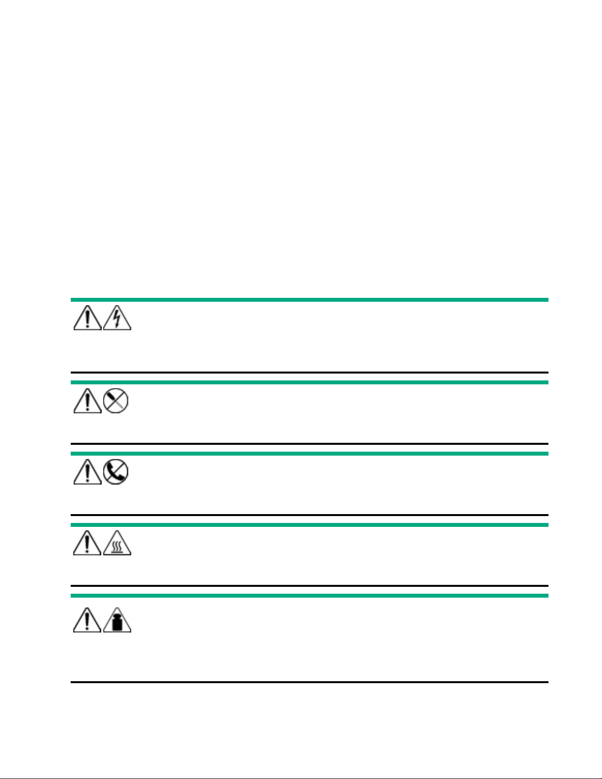
Removal and replacement procedures
Required tools
You need the following items for some procedures:
• T-10 Torx screwdriver
• T-15 Torx screwdriver
• T-30 Torx screwdriver
Safety considerations
Before performing service procedures, review all the safety information.
Symbols on equipment
The following symbols might be found on the equipment to indicate the presence of potentially hazardous conditions.
This symbol indicates the presence of hazardous energy circuits or electric shock hazards. Refer all
servicing to qualified personnel.
3412 kg
7523 lb
WARNING: To reduce the risk of injury from electric shock hazards, do not open this enclosure. Refer
all maintenance, upgrades, and servicing to qualified personnel.
This symbol indicates the presence of electric shock hazards. The area contains no user or field
serviceable parts. Do not open for any reason.
WARNING: To reduce the risk of injury from electric shock hazards, do not open this enclosure.
This symbol on an RJ-45 receptacle indicates a network interface connection.
WARNING: To reduce the risk of electric shock, fire, or damage to the equipment, do not plug telephone
or telecommunications connectors into this receptacle.
This symbol indicates the presence of a hot surface or hot component. If this surface is contacted, the
potential for injury exists.
WARNING: To reduce the risk of injury from a hot component, allow the surface to cool before touching.
This symbol indicates that the component exceeds the recommended weight for one individual to
handle safely.
WARNING: To reduce the risk of personal injury or damage to the equipment, observe local
occupational health and safety requirements and guidelines for manual material handling.
40 Removal and replacement procedures
Page 41
These symbols, on power supplies or systems, indicate that the equipment is supplied by multiple
sources of power.
WARNING: To reduce the risk of injury from electric shock, remove all power cords to disconnect power
from the system completely.
Server warnings and cautions
WARNING: This server is heavy. To reduce the risk of personal injury or damage to the equipment:
• Observe local occupational health and safety requirements and guidelines for manual material handling.
• Get help to lift and stabilize the product during installation or removal, especially when the product is not fastened
to the rails. Hewlett Packard Enterprise recommends that a minimum of two people are required for all rack server
installations. If the server is installed higher than chest level, a third person may be required to help align the server.
• Use caution when installing the server in or removing the server from the rack; it is unstable when not fastened to
the rails.
WARNING: To reduce the risk of personal injury from hot surfaces, allow the drives and the internal system components
to cool before touching them.
WARNING: To reduce the risk of personal injury, electric shock, or damage to the equipment, remove the power cord to
remove power from the server. The front panel Power On/Standby button does not completely shut o system power.
Portions of the power supply and some internal circuitry remain active until AC/DC power is removed.
WARNING: To reduce the risk of fire or burns after removing the energy pack:
• Do not disassemble, crush, or puncture the energy pack.
• Do not short external contacts.
• Do not dispose of the energy pack in fire or water.
After power is disconnected, battery voltage might still be present for 1s to 160s.
AVERTISSEMENT: Pour réduire les risques d'incendie ou de brûlures après le retrait du module batterie :
• N'essayez pas de démonter, d'écraser ou de percer le module batterie.
• Ne court-circuitez pas ses contacts externes.
• Ne jetez pas le module batterie dans le feu ou dans l'eau.
Après avoir déconnecté l'alimentation, une tension peut subsister dans la batterie durant 1 à 160 secondes.
CAUTION: Protect the server from power fluctuations and temporary interruptions with a regulating uninterruptible
power supply. This device protects the hardware from damage caused by power surges and voltage spikes and keeps
the system in operation during a power failure.
CAUTION: Do not operate the server for long periods with the access panel open or removed. Operating the server in
this manner results in improper airflow and improper cooling that can lead to thermal damage.
Removal and replacement procedures 41
Page 42

Preventing electrostatic discharge
To prevent damaging the system, be aware of the precautions you must follow when setting up the system or handling parts.
A discharge of static electricity from a finger or other conductor may damage system boards or other static-sensitive devices.
This type of damage may reduce the life expectancy of the device.
Procedure
• Avoid hand contact by transporting and storing products in static-safe containers.
• Keep electrostatic-sensitive parts in their containers until they arrive at static-free workstations.
• Place parts on a grounded surface before removing them from their containers.
• Avoid touching pins, leads, or circuitry.
• Always be properly grounded when touching a static-sensitive component or assembly.
Preparation procedures
Power down the server
Before powering down the server for any upgrade or maintenance procedures, perform a backup of critical server data and
programs.
IMPORTANT: When the server is in standby mode, auxiliary power is still being provided to the system.
To power down the server, use one of the following methods:
• Press and release the Power On/Standby button.
This method initiates a controlled shutdown of applications and the OS before the server enters standby mode.
• Press and hold the Power On/Standby button for more than 4 seconds to force the server to enter standby mode.
This method forces the server to enter standby mode without properly exiting applications and the OS. If an application
stops responding, you can use this method to force a shutdown.
• Use a virtual power button selection through iLO.
This method initiates a controlled remote shutdown of applications and the OS before the server enters standby mode.
Before proceeding, verify that the server is in standby mode by observing that the system power LED is amber.
Extend the server from the rack
WARNING: To reduce the risk of personal injury or equipment damage, be sure that the rack is adequately stabilized
before extending a component from the rack.
1. Pull down the quick release levers on each side of the server.
2. Extend the server from the rack.
42
Removal and replacement procedures
Page 43
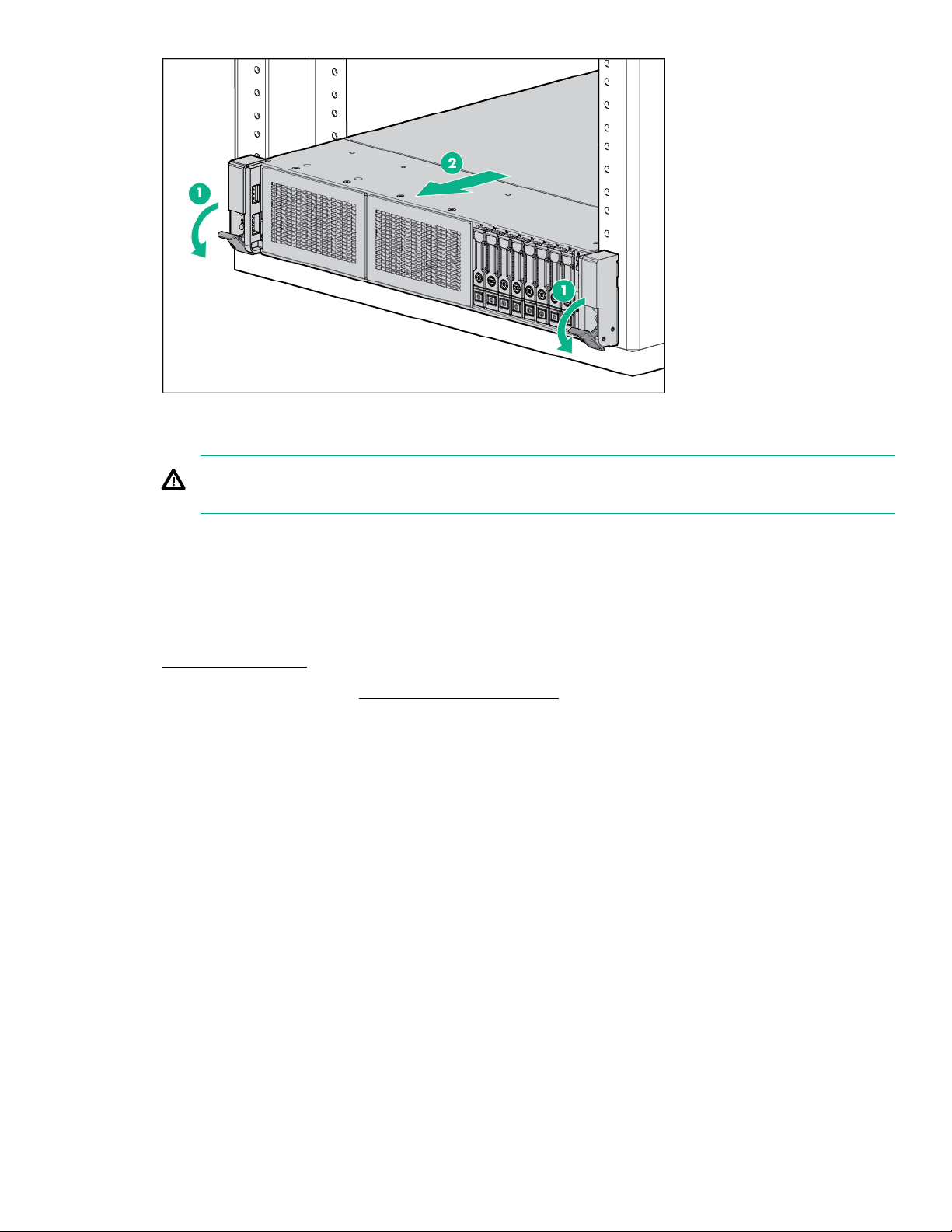
3. After performing the installation or maintenance procedure, slide the server back into the rack, and then press the server
firmly into the rack to secure it in place.
WARNING: To reduce the risk of personal injury, be careful when pressing the server rail-release latches and sliding
the server into the rack. The sliding rails could pinch your fingers.
Removing the server from the rack
To remove the server from a Hewlett Packard Enterprise, Compaq-branded, Telco, or third-party rack:
Procedure
Power down the server.
1.
Extend the server from the rack (Extend the server from the rack).
2.
Disconnect the cabling and remove the server from the rack.
3.
For more information, see the documentation that ships with the rack mounting option.
Place the server on a sturdy, level surface.
4.
Accessing the Systems Insight Display
Procedure
1. Press and release the panel.
2. After the display fully ejects, rotate the display to view the LEDs.
Removal and replacement procedures
43
Page 44
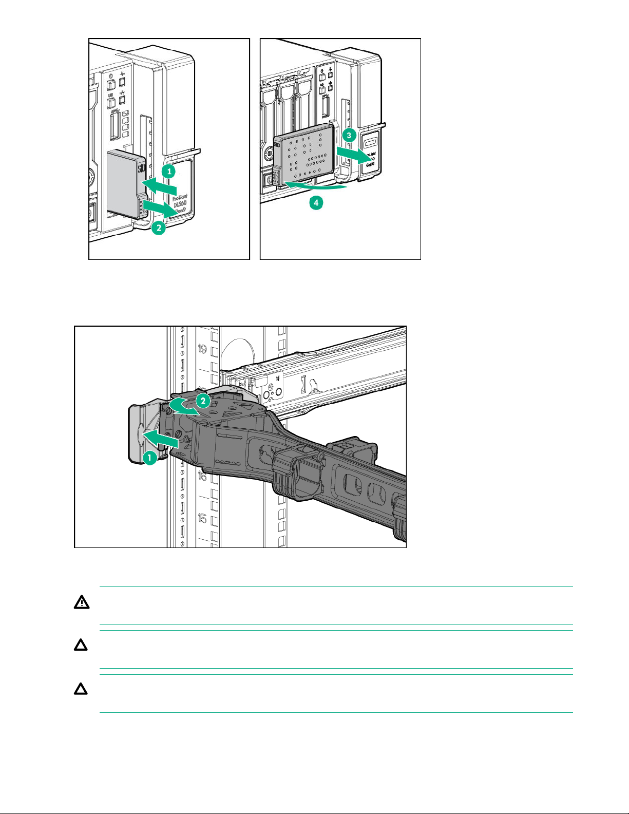
Release the cable management arm
Release the cable management arm and then swing the arm away from the rack.
Removing the access panel
WARNING: To reduce the risk of personal injury from hot surfaces, allow the drives and the internal system components
to cool before touching them.
CAUTION: To prevent damage to electrical components, take the appropriate anti-static precautions before beginning
any installation, removal, or replacement procedure. Improper grounding can cause electrostatic discharge.
CAUTION: Do not operate the server for long periods with the access panel open or removed. Operating the server in
this manner results in improper airflow and improper cooling that can lead to thermal damage.
44 Removal and replacement procedures
Page 45
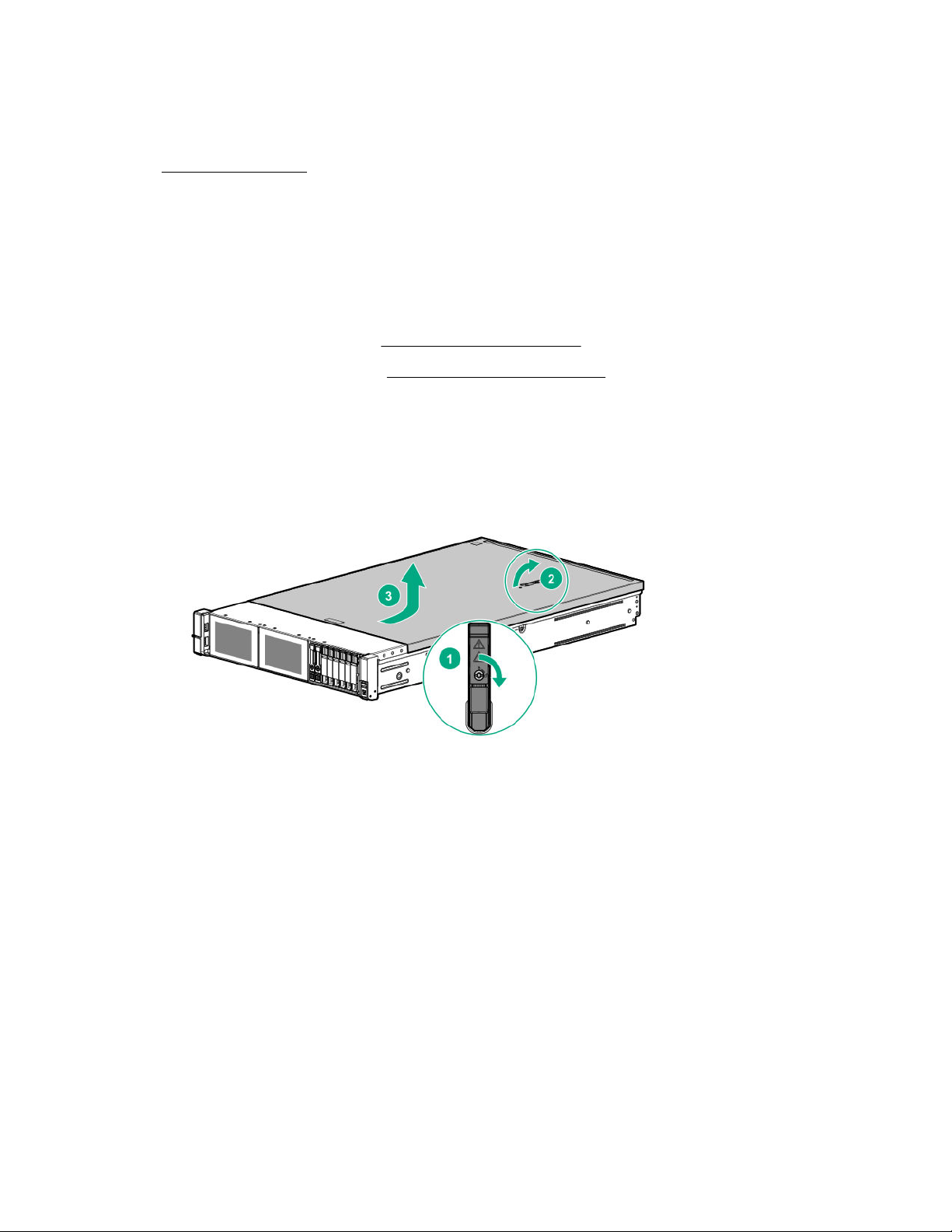
Prerequisites
A T-15 Torx screwdriver might be required to unlock the access panel.
Procedure
1. Power down the server.
2. Remove all power:
a. Disconnect each power cord from the power source.
b.
Disconnect each power cord from the server.
3. Do one of the following:
• Extend the server from the rack (
• Remove the server from the rack (Removing the server from the rack).
4. If the locking latch is locked, use a T-15 Torx screwdriver to unlock the latch.
5. Open the locking latch.
The access panel slides back, releasing it from the chassis.
Lift and remove the access panel.
6.
Turn the access panel over to locate the server label. This label provides convenient access to component identification and
LED status indicators.
Extend the server from the rack).
Removing the bezel
Procedure
Remove the component as indicated.
Removal and replacement procedures
45
Page 46
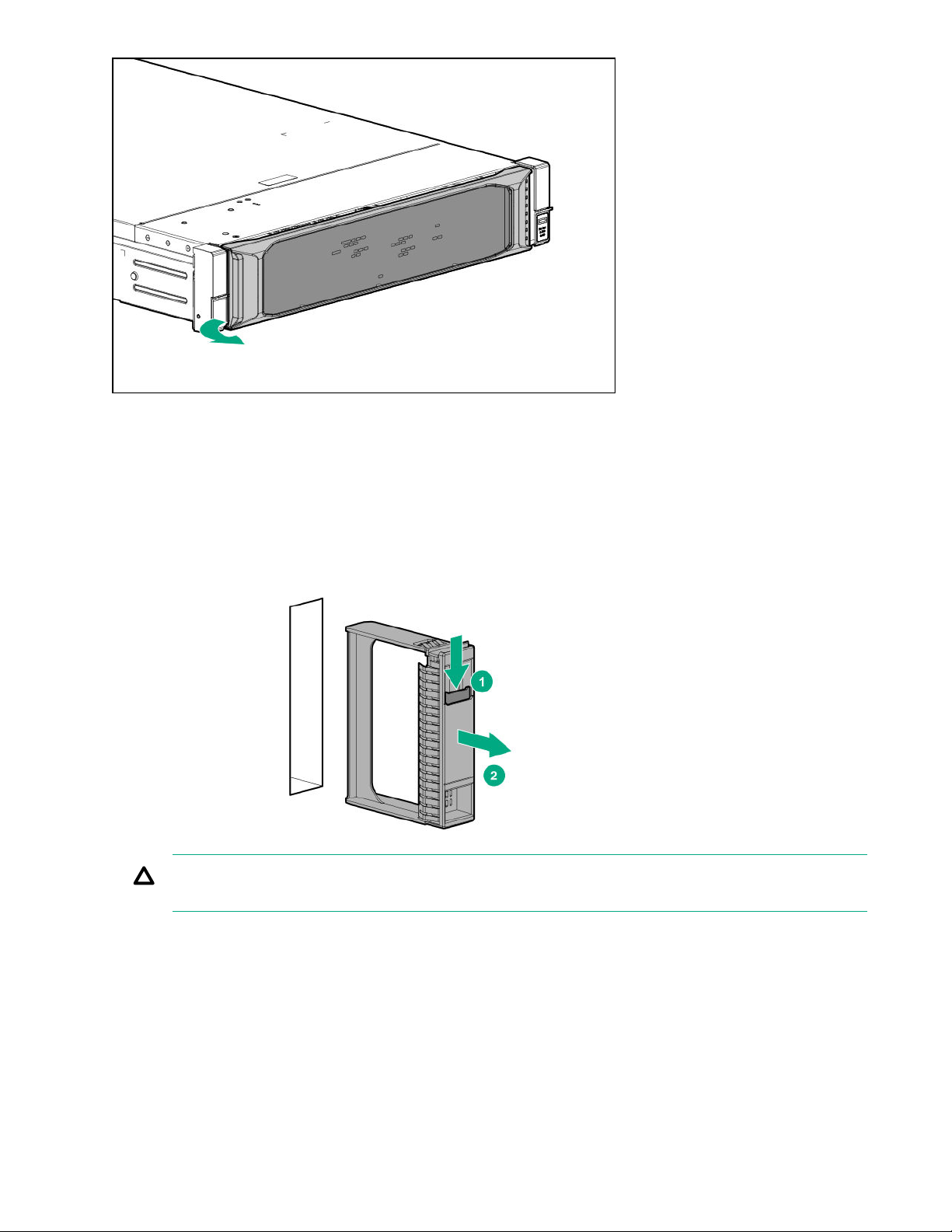
Removing and replacing a drive blank
Procedure
Press the drive release button.
1.
Remove the drive.
2.
CAUTION: To prevent improper cooling and thermal damage, do not operate the compute module unless all bays
are populated with either a component or a blank.
To replace the component, reverse the removal procedure.
46
Removal and replacement procedures
Page 47
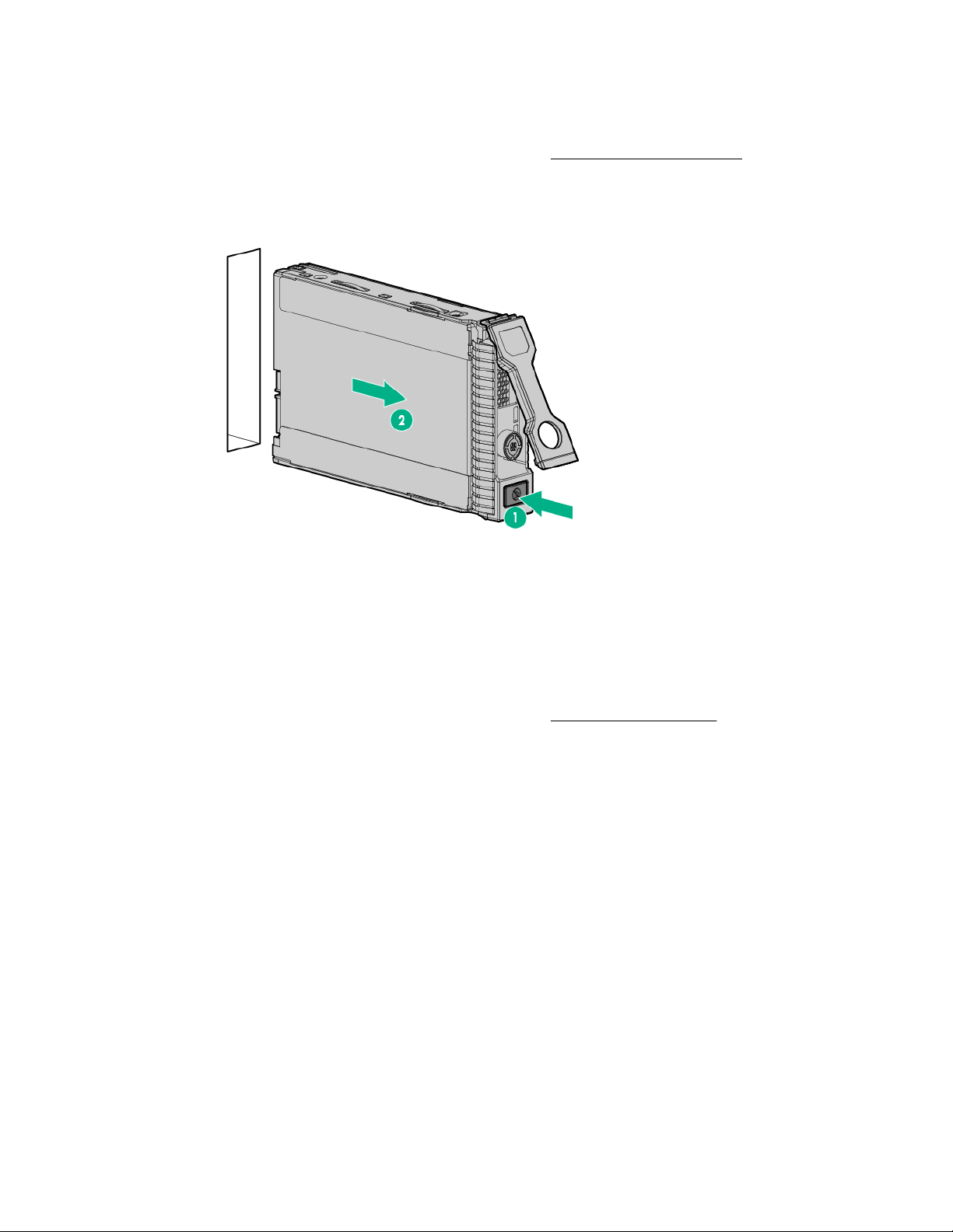
Removing and replacing a hot-plug SAS or SATA drive
Procedure
1. Determine the status of the drive from the drive LED definitions (Hot-plug drive LED definitions).
2. Back up all data on the drive.
3. Remove the drive.
To replace the drive, slide the drive into the bay until it is fully seated, and then close the latch handle.
Removing and replacing an NVMe drive
Procedure
Determine the status of the drive from the drive LED definitions (NVMe SSD LED definitions).
1.
Back up all server data.
2.
Remove the drive:
3.
Push the Power button.
a.
The Do Not Remove button will illuminate and flash. Do not press the button while it is illuminated.
b. When the flashing stops and the icon on the button is no longer illuminated or flashing, press the Do Not Remove
button to release the release lever.
c. Pull the release lever to disengage the drive from the backplane, and slide the drive out of the drive bay.
Removal and replacement procedures
47
Page 48
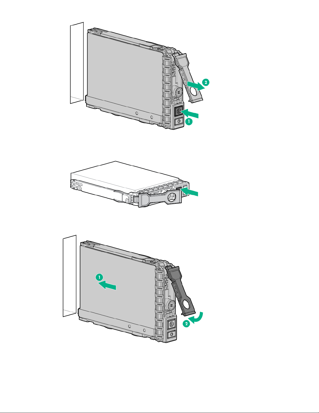
4. Prepare the replacement drive.
Install the drive.
5.
6. Observe the LED status of the drive.
48
Removal and replacement procedures
Page 49
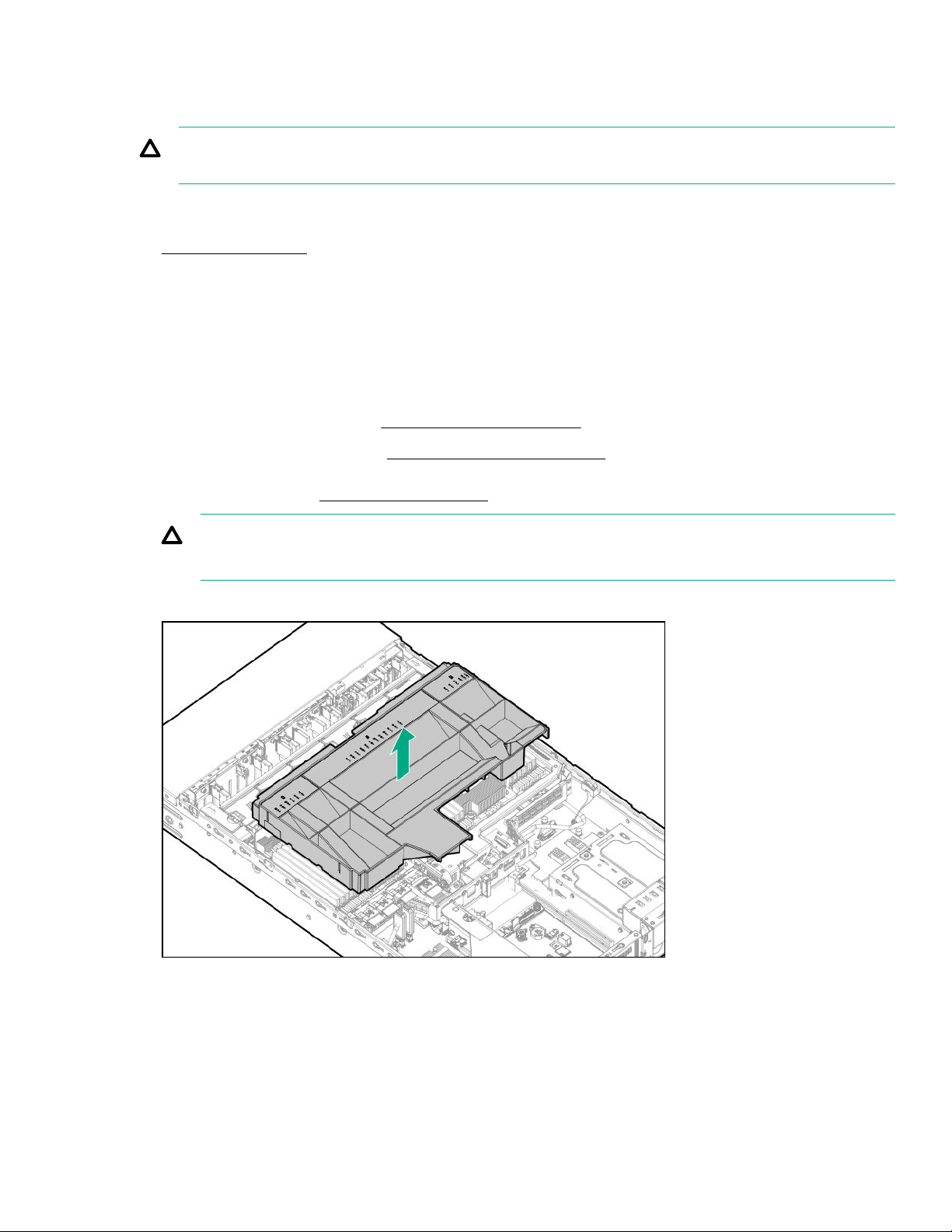
Removing and replacing the air bale
The air bale must be installed in one- and two-processor configurations.
CAUTION: For proper cooling, do not operate the server without the access panel, bales, expansion slot covers, or
blanks installed. If the server supports hot-plug components, minimize the amount of time the access panel is open.
Procedure
Power down the server.
1.
2. Remove all power:
a. Disconnect each power cord from the power source.
b. Disconnect each power cord from the server.
3. Do one of the following:
• Extend the server from the rack (Extend the server from the rack).
• Remove the server from the rack (Removing the server from the rack).
Remove the access panel (
4.
CAUTION: Do not operate the server for long periods with the access panel open or removed. Operating the server
in this manner results in improper airflow and improper cooling that can lead to thermal damage.
Remove the air
5.
bale.
Removing the access panel).
To replace the component, reverse the removal procedure.
Removal and replacement procedures
49
Page 50
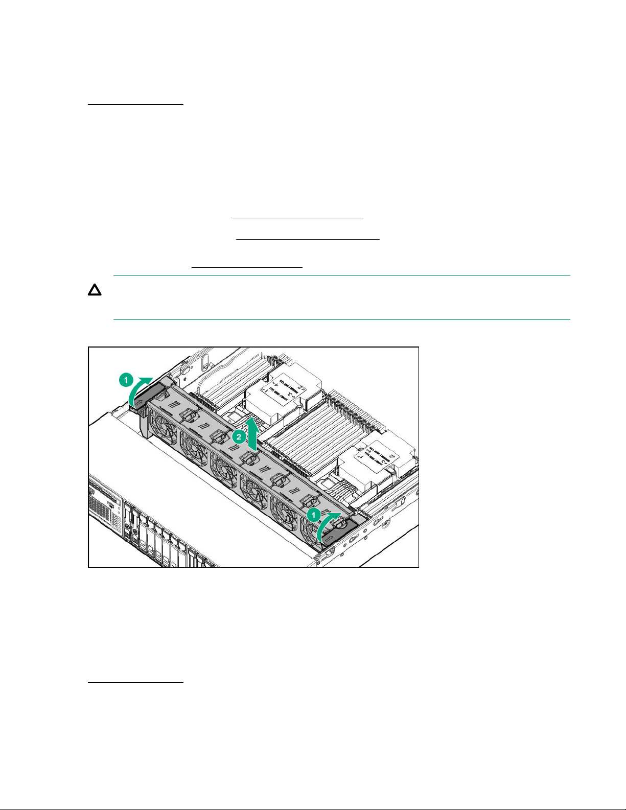
Removing and replacing the fan cage
Procedure
1. Power down the server.
2. Remove all power:
a. Disconnect each power cord from the power source.
b. Disconnect each power cord from the server.
3. Do one of the following:
• Extend the server from the rack (
• Remove the server from the rack (Removing the server from the rack).
4. Remove the access panel (
CAUTION: Do not operate the server for long periods with the access panel open or removed. Operating the server
in this manner results in improper airflow and improper cooling that can lead to thermal damage.
Remove the fan cage.
5.
Removing the access panel).
Extend the server from the rack).
To replace the component, reverse the removal procedure.
Removing and replacing the fan cage louvers
Procedure
1. Power down the server.
2. Remove all power:
50
Removal and replacement procedures
Page 51
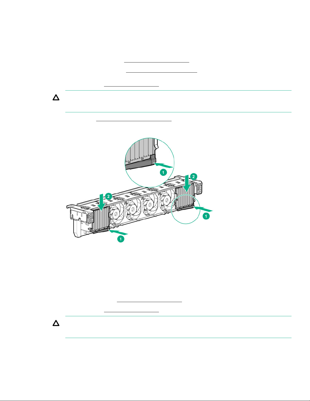
a. Disconnect each power cord from the power source.
b. Disconnect each power cord from the server.
3. Do one of the following:
• Extend the server from the rack (Extend the server from the rack).
• Remove the server from the rack (Removing the server from the rack).
4. Remove the access panel (Removing the access panel).
CAUTION: Do not operate the server for long periods with the access panel open or removed. Operating the server
in this manner results in improper airflow and improper cooling that can lead to thermal damage.
5. Remove the fan cage (Removing and replacing the fan cage).
6. Press the latch, and then slide the louver from fan cage.
To replace the component, reverse the removal procedure.
Removing and replacing the hot-plug fan
Procedure
1. Extend the server from the rack (
2. Remove the access panel (Removing the access panel).
CAUTION: Do not operate the server for long periods with the access panel open or removed. Operating the server
in this manner results in improper airflow and improper cooling that can lead to thermal damage.
3. Remove the fan.
Extend the server from the rack).
Removal and replacement procedures
51
Page 52
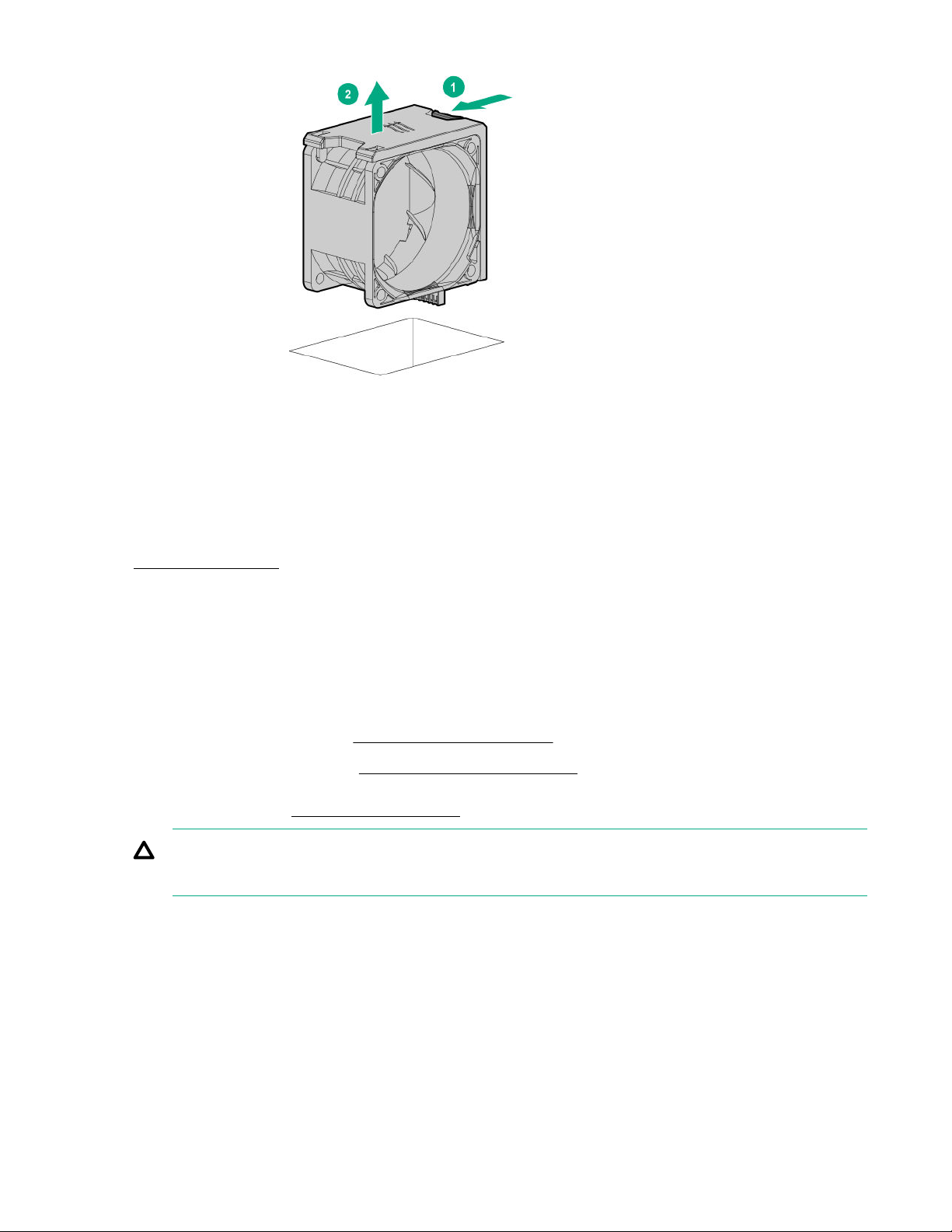
To replace the component, reverse the removal procedure.
Removing and replacing the processor mezzanine tray
Procedure
Power down the server.
1.
Remove all power:
2.
Disconnect each power cord from the power source.
a.
Disconnect each power cord from the server.
b.
Do one of the following:
3.
• Extend the server from the rack (
• Remove the server from the rack (Removing the server from the rack).
Remove the access panel (
4.
CAUTION: Do not operate the server for long periods with the access panel open or removed. Operating the server
in this manner results in improper airflow and improper cooling that can lead to thermal damage.
5. Remove the processor mezzanine tray.
52
Removal and replacement procedures
Extend the server from the rack).
Removing the access panel).
Page 53
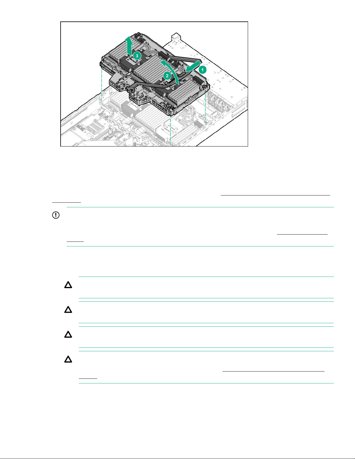
To replace the component, reverse the removal procedure.
Removing and replacing a processor
Before performing this procedure, Hewlett Packard Enterprise recommends identifying the processor, heatsink, and socket
components.
IMPORTANT: Existing HPE ProLiant and HPE Synergy Gen10 server products containing first-generation Intel Xeon
Scalable processors may not be upgraded to second-generation Intel Xeon Scalable processors at this time.
For more information, see the product QuickSpecs on the Hewlett Packard Enterprise website (
info/qs).
Procedure
Observe the following alerts.
1.
CAUTION: When handling the heatsink, always hold it along the top and bottom of the fins. Holding it from the
sides can damage the fins.
CAUTION: To avoid damage to the processor or system board, only authorized personnel should attempt to
replace or install the processor in this server.
CAUTION: To prevent possible server malfunction and damage to the equipment, multiprocessor configurations
must contain processors with the same part number.
CAUTION: If installing a processor with a faster speed, update the system ROM before installing the processor.
To download firmware and view installation instructions, see the Hewlett Packard Enterprise Support Center
website.
http://www.hpe.com/
Removal and replacement procedures 53
Page 54

CAUTION: THE CONTACTS ARE VERY FRAGILE AND EASILY DAMAGED. To avoid damage to the socket or
processor, do not touch the contacts.
2. Power down the server.
3. Remove all power:
a. Disconnect each power cord from the power source.
b. Disconnect each power cord from the server.
4. Do one of the following:
• Extend the server from the rack (
• Remove the server from the rack (Removing the server from the rack).
5. Remove the access panel (
CAUTION: Do not operate the server for long periods with the access panel open or removed. Operating the server
in this manner results in improper airflow and improper cooling that can lead to thermal damage.
If installed, do the following:
6.
Remove the air bale (Removing and replacing the air bale).
a.
Remove the processor mezzanine tray (
b.
Remove the CPU Mezzanine UPI performance kit (Removing and replacing the CPU Mezzanine UPI performance
c.
kit).
NOTE: Depending on the server configuration, your heatsink might appear
Remove the processor and heatsink assembly:
7.
Allow the heatsink to cool.
a.
Removing the access panel).
Extend the server from the rack).
Removing and replacing the processor mezzanine tray).
dierent.
Loosen the heatsink nuts in the order specified by the label on the heatsink (4 - 3 - 2 - 1).
b.
54
Removal and replacement procedures
Page 55
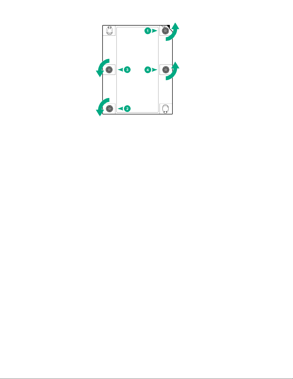
c. Lift the processor heatsink assembly up and away from the system board.
d. Turn the assembly over and place it on a work surface with the processor facing up.
Install the dust cover.
e.
Install the processor heatsink assembly:
8.
Locate the Pin 1 indicator on the processor carrier and the socket.
a.
Align the processor heatsink assembly with the heatsink alignment pins and gently lower it down until it sits evenly
b.
on the socket.
The heatsink alignment pins are keyed. The processor heatsink assembly will only install one way.
Your heatsink may look
dierent than the one shown.
Removal and replacement procedures
55
Page 56
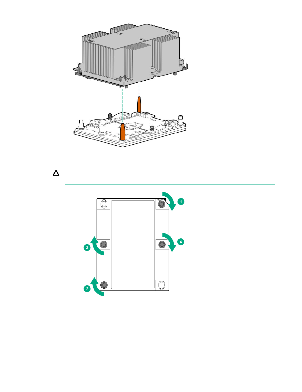
Using a T-30 Torx screwdriver, fully tighten each heatsink nut until it no longer turns.
c.
CAUTION: Be sure to tighten each heatsink nut fully in the order indicated. Otherwise, boot failure or
intermittent shutdowns might occur.
9. If removed, do the following:
a. Install the air bale.
b. Install the processor mezzanine tray.
c. Install the CPU Mezzanine UPI performance kit.
56
Removal and replacement procedures
Page 57

10. Install the access panel.
11. Install the server into the rack.
12. Connect each power cord to the server.
13. Connect each power cord to the power source.
14. Power up the server.
Removing and replacing a DIMM
CAUTION: Failure to properly handle DIMMs can damage the DIMM components and the system board connector. For
more information, see the DIMM handling guidelines in the troubleshooting guide for your product on the Hewlett
Packard Enterprise website:
• HPE ProLiant Gen10 (
• HPE Synergy (
For specific DIMM population information, see the DIMM population guidelines on the Hewlett Packard Enterprise website
(http://www.hpe.com/docs/memory-population-rules).
To identify the DIMMs installed in the server, see DIMM slot locations.
Procedure
Power down the server.
1.
Remove all power:
2.
Disconnect each power cord from the power source.
a.
Disconnect each power cord from the server.
b.
Do one of the following:
3.
• Extend the server from the rack (
• Remove the server from the rack (Removing the server from the rack).
Remove the access panel (Removing the access panel).
4.
https://www.hpe.com/info/gen10-troubleshooting)
https://www.hpe.com/info/synergy-troubleshooting)
Extend the server from the rack).
CAUTION: Do not operate the server for long periods with the access panel open or removed. Operating the server
in this manner results in improper airflow and improper cooling that can lead to thermal damage.
5. If installed, do the following:
a. Remove the air bale (Removing and replacing the air bale).
b. Remove the processor mezzanine tray (
c. Remove the CPU Mezzanine UPI performance kit (Removing and replacing the CPU Mezzanine UPI performance kit).
6. Remove the DIMM.
Removing and replacing the processor mezzanine tray).
Removal and replacement procedures
57
Page 58
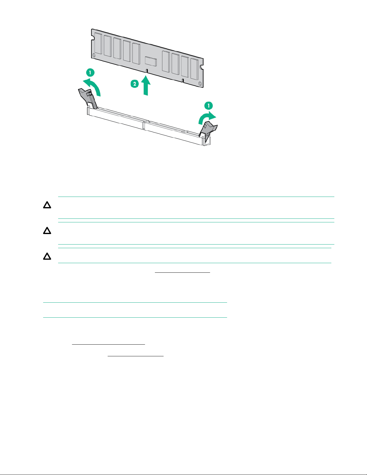
To replace the component, reverse the removal procedure.
Removing and replacing an NVDIMM
CAUTION: Do not remove an NVDIMM when any LEDs on any NVDIMM in the system are illuminated. Removing an
NVDIMM when an LED is illuminated might cause a loss of data.
CAUTION: Electrostatic discharge can damage electronic components. Be sure you are properly grounded before
beginning this procedure.
CAUTION: Failure to properly handle DIMMs can cause damage to DIMM components and the system board connector.
To identify NVDIMMs installed in the server, see NVDIMM identification
Prerequisites
Before replacing memory, read the memory configuration and population guidelines in the server user guide.
NOTE: To support NVDIMMs, you must install two HPE Smart Storage batteries.
Procedure
1. Observe
2. Power down the server (Power down the server).
3. Remove all power:
a. Disconnect each power cord from the power source.
b. Disconnect each power cord from the server.
4. Do one of the following:
58
Removal and replacement procedures
NVDIMM relocation guidelines.
Page 59
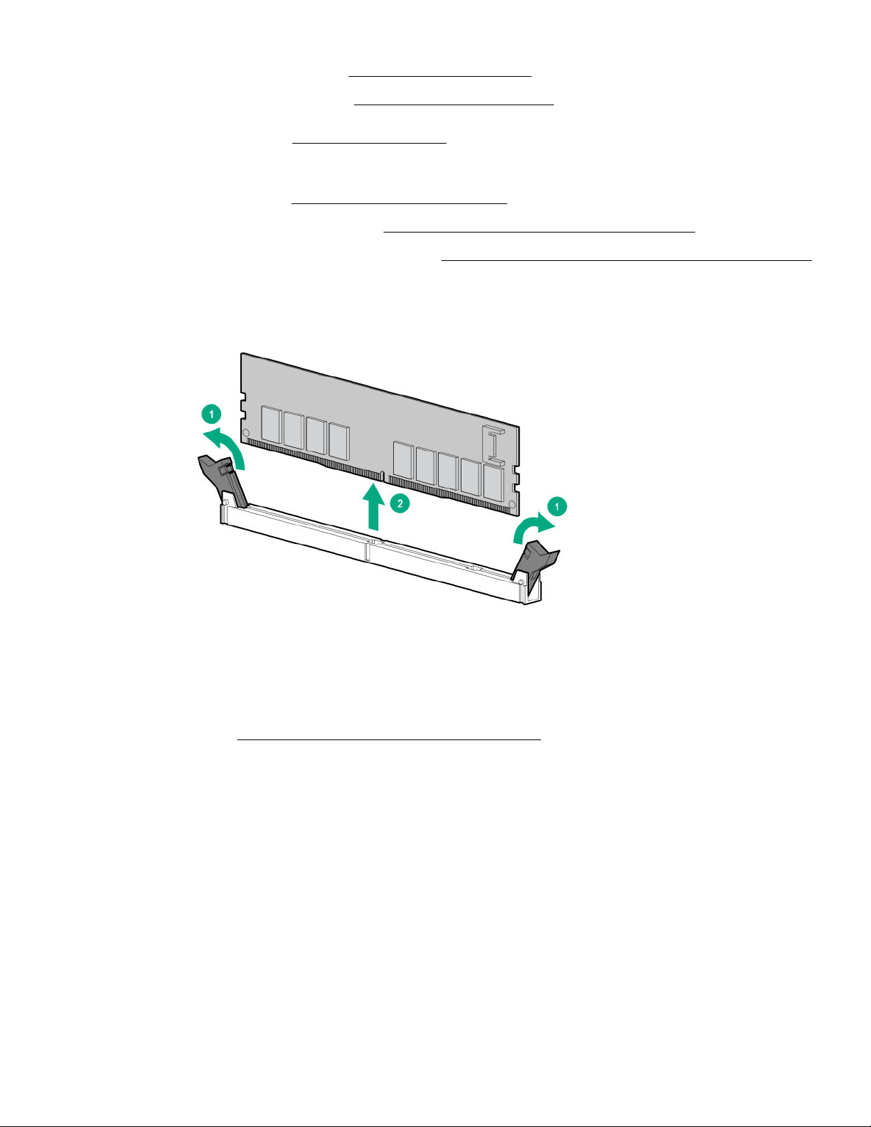
• Extend the server from the rack (Extend the server from the rack).
• Remove the server from the rack (Removing the server from the rack).
5. Remove the access panel (Removing the access panel).
6. If installed, do the following:
a. Remove the air bale (Removing and replacing the air bale).
b. Remove the processor mezzanine tray (Removing and replacing the processor mezzanine tray).
c. Remove the CPU Mezzanine UPI performance kit (Removing and replacing the CPU Mezzanine UPI performance kit).
7. Observe the NVDIMM LEDs. Do not remove an NVDIMM when any NVDIMM LED in the system is illuminated.
8. Remove the NVDIMM-N.
To replace the component, reverse the removal procedure.
DIMM and NVDIMM population information
For specific DIMM and NVDIMM population information, see the DIMM population guidelines on the Hewlett Packard
Enterprise website (http://www.hpe.com/docs/memory-population-rules).
NVDIMM sanitization
Media sanitization is defined by NIST SP800-88 Guidelines for Media Sanitization (Rev 1, Dec 2014) as "a general term
referring to the actions taken to render data written on media unrecoverable by both ordinary and extraordinary means."
The specification defines the following levels:
• Clear: Overwrite user-addressable storage space using standard write commands; might not sanitize data in areas not
currently user-addressable (such as bad blocks and overprovisioned areas)
• Purge: Overwrite or erase all storage space that might have been used to store data using dedicated device sanitize
commands, such that data retrieval is "infeasible using state-of-the-art laboratory techniques"
• Destroy: Ensure that data retrieval is "infeasible using state-of-the-art laboratory techniques" and render the media unable
to store data (such as disintegrate, pulverize, melt, incinerate, or shred)
Removal and replacement procedures
59
Page 60

The NVDIMM-N Sanitize options are intended to meet the Purge level.
For more information on sanitization for NVDIMMs, see the following sections in the HPE 16GB NVDIMM User Guide on the
Hewlett Packard Enterprise website (http://www.hpe.com/info/nvdimm-docs):
• NVDIMM sanitization policies
• NVDIMM sanitization guidelines
• Setting the NVDIMM-N Sanitize/Erase on the Next Reboot Policy
NIST SP800-88 Guidelines for Media Sanitization (Rev 1, Dec 2014) is available for download from the NIST website (
nvlpubs.nist.gov/nistpubs/SpecialPublications/NIST.SP.800-88r1.pdf).
NVDIMM relocation guidelines
Requirements for relocating NVDIMMs or a set of NVDIMMs when the data must be preserved
• The destination server hardware must match the original server hardware configuration.
• All System Utilities settings in the destination server must match the original System Utilities settings in the original server.
• If NVDIMM-Ns are used with NVDIMM Interleaving ON mode in the original server, do the following:
◦ Install the NVDIMMs in the same DIMM slots in the destination server.
◦ Install the entire NVDIMM set (all the NVDIMM-Ns on the processor) on the destination server.
This guideline would apply when replacing a system board due to system failure.
If any of the requirements cannot be met during NVDIMM relocation, do the following:
◦ Manually back up the NVDIMM-N data before relocating NVDIMM-Ns to another server.
◦ Relocate the NVDIMM-Ns to another server.
◦ Sanitize all NVDIMM-Ns on the new server before using them.
http://
Requirements for relocating NVDIMMs or a set of NVDIMMs when the data does not have to be preserved
If data on the NVDIMM-N or set of NVDIMM-Ns does not have to be preserved, then
• Move the NVDIMM-Ns to the new location and sanitize all NVDIMM-Ns after installing them to the new location. For more
information, see NVDIMM sanitization.
• Observe all DIMM and NVDIMM population guidelines. For more information, see
information.
• Observe the process for removing an NVDIMM.
• Observe the process for installing an NVDIMM.
• Review and configure the system settings for NVDIMMs. For more information, see
Recovering restored data from an NVDIMM-N DRAM
CAUTION: Do not remove an NVDIMM when any LEDs on any NVDIMM in the system are illuminated. Removing an
NVDIMM when an LED is illuminated might cause a loss of data.
DIMM and NVDIMM population
Configuring the server for NVDIMMs .
60 Removal and replacement procedures
Page 61

CAUTION: Electrostatic discharge can damage electronic components. Be sure you are properly grounded before
beginning this procedure.
CAUTION: Failure to properly handle DIMMs can damage the DIMM components and the system board connector. For
more information, see the DIMM handling guidelines in the troubleshooting guide for your product on the Hewlett
Packard Enterprise website:
• HPE ProLiant Gen10 (https://www.hpe.com/info/gen10-troubleshooting)
• HPE Synergy (
When the NVDIMM-N DRAM contains the only copy of restored data, perform the following procedure to recover the
information:
Procedure
1. Copy the data from the NVDIMM to some other storage device (such as SSD, HDD, or another NVDIMM) as soon as
possible (before cold reset or power loss).
2. Power down the server.
Extend or remove the server.
3.
Remove the access panel.
4.
Remove all components necessary to access the server DIMM slots and the HPE Smart Storage Battery.
5.
For more information, see the server maintenance and service guide on the Hewlett Packard Enterprise website (
www.hpe.com/info/enterprise-docs).
Observe the NVDIMM LEDs. Do not remove an NVDIMM when any NVDIMM LED in the system is illuminated.
6.
Remove the NVDIMM-N.
7.
Install a replacement NVDIMM-N.
8.
https://www.hpe.com/info/synergy-troubleshooting)
http://
Install any components removed to access the DIMM slots and the HPE Smart Storage Battery.
9.
Install the access panel.
10.
Install the server in the rack.
11.
Power up the server.
12.
Sanitize the replacement NVDIMM.
13.
14. Copy the data from the storage device to the NVDIMM-N.
Configuring the server for NVDIMMs
After installing NVDIMMs, configure the server for NVDIMMs. For information on configuring settings for NVDIMMs, see the
HPE 16GB NVDIMM User Guide on the Hewlett Packard Enterprise website (http://www.hpe.com/info/nvdimm-docs).
The server can be configured for NVDIMMs using either of the following:
Removal and replacement procedures
61
Page 62

• UEFI System Utilities—Use System Utilities through the Remote Console to configure the server for NVDIMM memory
options by pressing the F9 key during POST. For more information about UEFI System Utilities, see the Hewlett Packard
Enterprise website (http://www.hpe.com/info/uefi/docs).
• iLO RESTful API for HPE iLO 5—For more information about configuring the system for NVDIMMs, see https://
hewlettpackard.github.io/ilo-rest-api-docs/ilo5/.
Removing and replacing an HPE Persistent Memory module
For specific population and configuration information, see the memory population guidelines on the Hewlett Packard
Enterprise website (http://www.hpe.com/docs/memory-population-rules).
To identify the HPE Persistent Memory modules installed in the server, see
identification.
Procedure
1. Observe the following alerts:
CAUTION: Electrostatic discharge can damage electronic components. Be sure you are properly grounded before
beginning this procedure.
CAUTION: Failure to properly handle HPE Persistent Memory modules can damage the component and the system
board connector.
Power down the server.
2.
Shut down the OS as directed by the OS documentation.
a.
To place the server in standby mode, press the Power On/Standby button. When the server enters standby power
b.
mode, the system power LED changes to amber.
Disconnect the power cords (rack and tower servers).
c.
Do one of the following:
3.
HPE Persistent Memory module label
Extend the server from the rack.
•
• Remove the server from the rack, if necessary.
Place the server on a flat, level work surface.
4.
Remove the access panel.
5.
6. If installed, do the following:
a. Remove the air
b. Remove the processor mezzanine tray (Removing and replacing the processor mezzanine tray).
c. Remove the CPU Mezzanine UPI performance kit (
7. Remove the HPE Persistent Memory module.
62
Removal and replacement procedures
bale (Removing and replacing the air bale).
Removing and replacing the CPU Mezzanine UPI performance kit).
Page 63
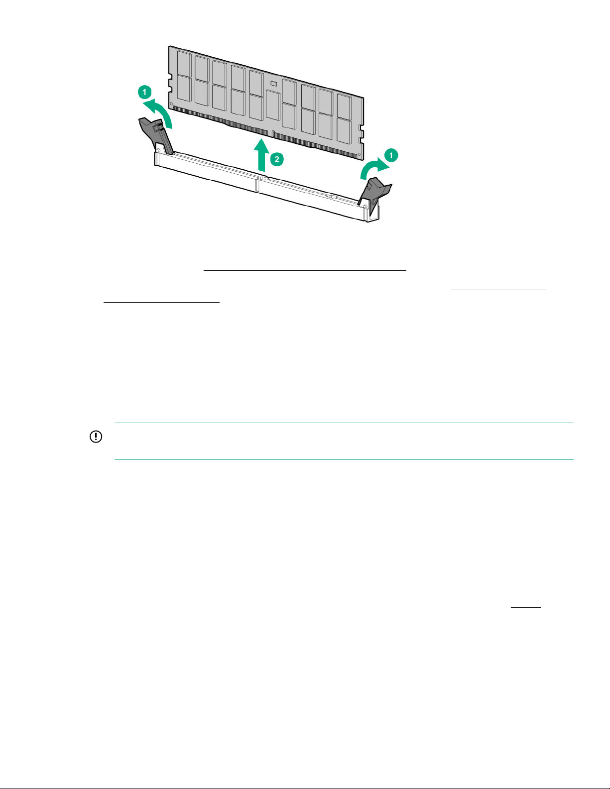
8. Install the new HPE Persistent Memory module, and review the persistent memory configuration of the server.
For more information, see Configuring the server for HPE Persistent Memory.
9. If you are relocating the HPE Persistent Memory module to or from another server, see the HPE Persistent Memory
module relocation guidelines.
HPE Persistent Memory module-processor compatibility
HPE Persistent Memory modules are supported only in servers with second-generation Intel Xeon Scalable processors
installed.
Configuring the server for HPE Persistent Memory
After installing HPE Persistent Memory modules, configure the server for HPE Persistent Memory.
IMPORTANT: Always follow recommendations from your software application provider for high-availability best
practices to ensure maximum uptime and data protection.
A number of configuration tools are available, including:
• UEFI System Utilities—Access System Utilities through the Remote Console to configure the server by pressing the F9 key
during POST.
• iLO RESTful API—Use the iLO RESTful API through tools such as the RESTful Interface Tool (ilorest) or other third-party
tools.
• HPE Persistent Memory Management Utility—The HPE Persistent Memory Management Utility is a desktop application
used to configure the server for HPE Persistent Memory, as well as evaluate and monitor the server memory configuration
layout.
For more information, see the HPE Persistent Memory User Guide on the Hewlett Packard Enterprise website (https://
www.hpe.com/info/persistentmemory-docs).
HPE Persistent Memory module relocation guidelines
Observe the relocation guidelines when doing the following:
Removal and replacement procedures
63
Page 64

• When relocating HPE Persistent Memory modules to another DIMM slot on the server.
• When relocating HPE Persistent Memory modules to another server.
• When reinstalling HPE Persistent Memory modules after replacing the server system board.
IMPORTANT: When data must be preserved, Hewlett Packard Enterprise strongly recommends that you perform a
manual backup of all user data on the HPE Persistent Memory modules before changing the goal configuration or
performing relocation procedures.
Requirements for relocating HPE Persistent Memory modules or a set of HPE Persistent Memory modules when the data
must be preserved
• The destination server hardware must match the original server hardware configuration.
• All System Utilities settings in the destination server must match the original System Utilities settings in the original server.
• If HPE Persistent Memory modules are used with Persistent Memory Interleaving set to Enabled in the original server, do
the following:
◦ Install the HPE Persistent Memory modules in the same DIMM slots in the destination server.
◦ Install the entire interleaved set (all the DIMMs and HPE Persistent Memory modules on the processor) on the
destination server.
If any of the requirements cannot be met during relocation, do the following:
◦ Manually back up the persistent memory data before relocating HPE Persistent Memory modules to another server.
◦ Relocate the HPE Persistent Memory modules to another server.
◦ Sanitize all HPE Persistent Memory modules on the new server before using them.
Requirements for relocating encrypted HPE Persistent Memory modules or a set of HPE Persistent Memory modules
when the data must be preserved
• If HPE Persistent Memory modules are encrypted with local key management, either manually retrieve the HPE Persistent
Memory module passwords from the server (user-generated passwords only) or export a password file to a USB key.
Hewlett Packard Enterprise recommends exporting the password file to a USB key.
• Follow the requirements for relocating HPE Persistent Memory modules or a set of HPE Persistent Memory modules when
the data must be preserved.
• Do one of the following:
◦ If HPE Persistent Memory modules are encrypted with local key management, either manually enter the HPE Persistent
Memory module passwords in the System Utilities or import the password file from the USB key.
◦ If HPE Persistent Memory modules are encrypted with remote key management, enroll the HPE iLO in the key
management server to provide access to the data on the HPE Persistent Memory modules.
For more information, see the HPE Persistent Memory User Guide on the Hewlett Packard Enterprise website (
www.hpe.com/info/persistentmemory-docs).
https://
64
Removal and replacement procedures
Page 65

Requirements for relocating HPE Persistent Memory modules or a set of HPE Persistent Memory modules when the data
does not have to be preserved
• Move the HPE Persistent Memory modules to the new location and sanitize all HPE Persistent Memory modules after
installing them to the new location.
• Observe the DIMM and HPE Persistent Memory module population guidelines.
• Observe the process for removing an HPE Persistent Memory module.
• Observe the process for installing an HPE Persistent Memory module.
• Review and configure the system settings for HPE Persistent Memory.
For more information, see the HPE Persistent Memory User Guide on the Hewlett Packard Enterprise website (https://
www.hpe.com/info/persistentmemory-docs).
HPE Persistent Memory module sanitization
Media sanitization is defined by NIST SP800-88 Guidelines for Media Sanitization (Rev 1, Dec 2014) as "a general term
referring to the actions taken to render data written on media unrecoverable by both ordinary and extraordinary means."
The specification defines the following levels:
• Clear: Overwrite user-addressable storage space using standard write commands; might not sanitize data in areas not
currently user-addressable (such as bad blocks and over-provisioned areas).
• Purge: Overwrite or erase all storage space that might have been used to store data using dedicated device sanitize
commands, such that data retrieval is "infeasible using state-of-the-art laboratory techniques."
• Destroy: Ensure that data retrieval is "infeasible using state-of-the-art laboratory techniques" and render the media unable
to store data (such as disintegrate, pulverize, melt, incinerate, or shred).
HPE Persistent Memory supports the purge level using a cryptographic erase technique and an overwrite technique.
HPE ProLiant and HPE Synergy Gen10 server products support sanitizing HPE Persistent Memory modules during POST. Use
the HPE RESTful Interface Tool or UEFI System Utilities to schedule sanitization on the next boot.
For more information, see the following sections in the HPE Persistent Memory User Guide on the Hewlett Packard Enterprise
website (https://www.hpe.com/info/persistentmemory-docs):
• Sanitization policies
• Sanitization guidelines
NIST SP800-88 Guidelines for Media Sanitization (Rev 1, Dec 2014) is available for download from the NIST website (https://
nvlpubs.nist.gov/nistpubs/SpecialPublications/NIST.SP.800-88r1.pdf).
Removing and replacing the CPU Mezzanine UPI performance kit
Procedure
Power down the server.
1.
2. Remove all power:
a. Disconnect each power cord from the power source.
b. Disconnect each power cord from the server.
Removal and replacement procedures
65
Page 66
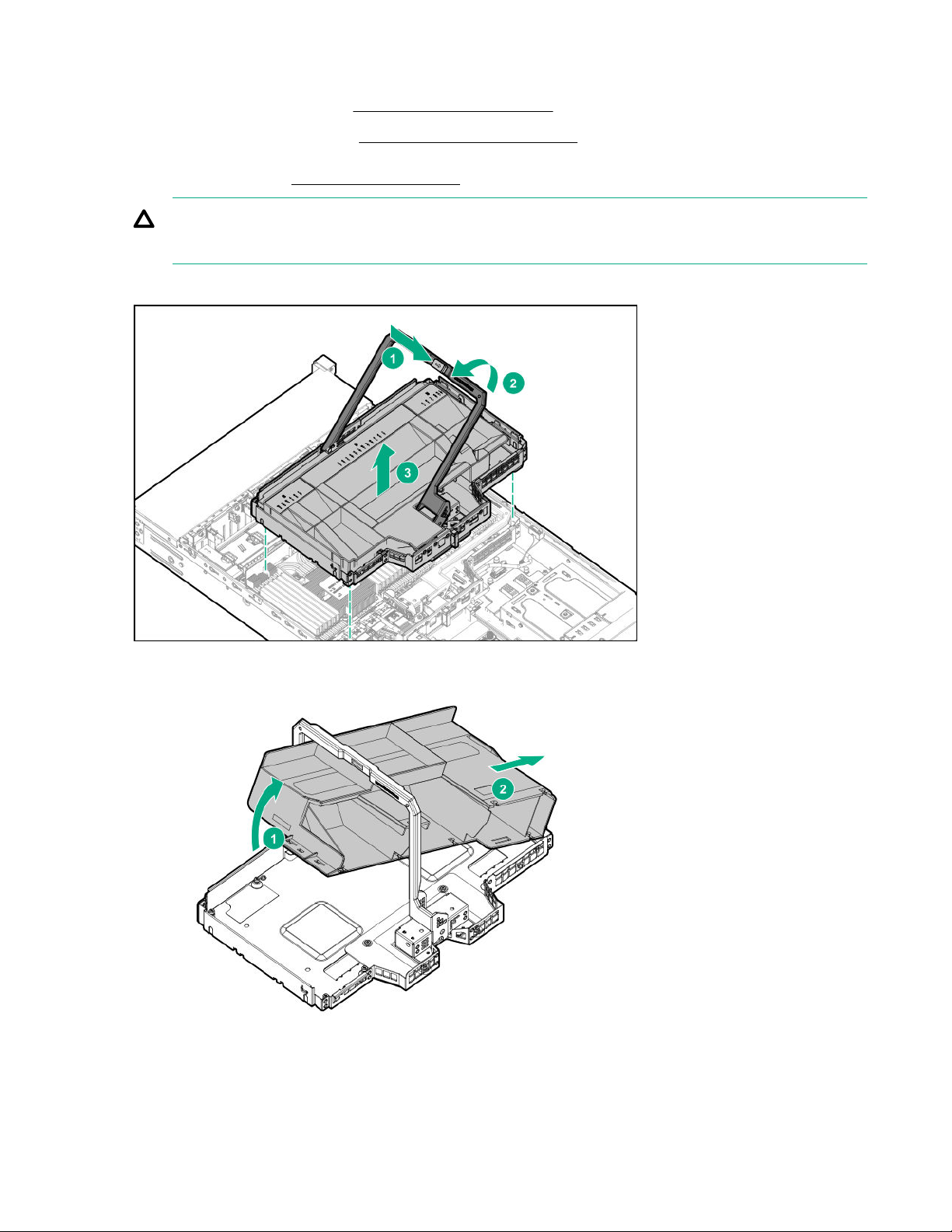
3. Do one of the following:
• Extend the server from the rack (Extend the server from the rack).
• Remove the server from the rack (
4. Remove the access panel (
CAUTION: Do not operate the server for long periods with the access panel open or removed. Operating the server
in this manner results in improper airflow and improper cooling that can lead to thermal damage.
5. Remove the CPU Mezzanine UPI performance kit.
Removing the access panel).
Removing the server from the rack).
Remove the air bale.
6.
7. Remove the handle.
66
Removal and replacement procedures
Page 67
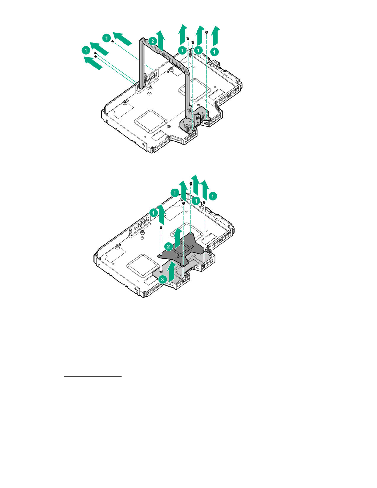
8. Remove the bracket to access the board, and then remove the board.
To replace the component, reverse the removal procedure.
Removing and replacing a 4-port NVMe mezzanine card
Procedure
1. Power down the server.
2. Remove all power:
a. Disconnect each power cord from the power source.
b. Disconnect each power cord from the server.
3. Do one of the following:
Removal and replacement procedures
67
Page 68
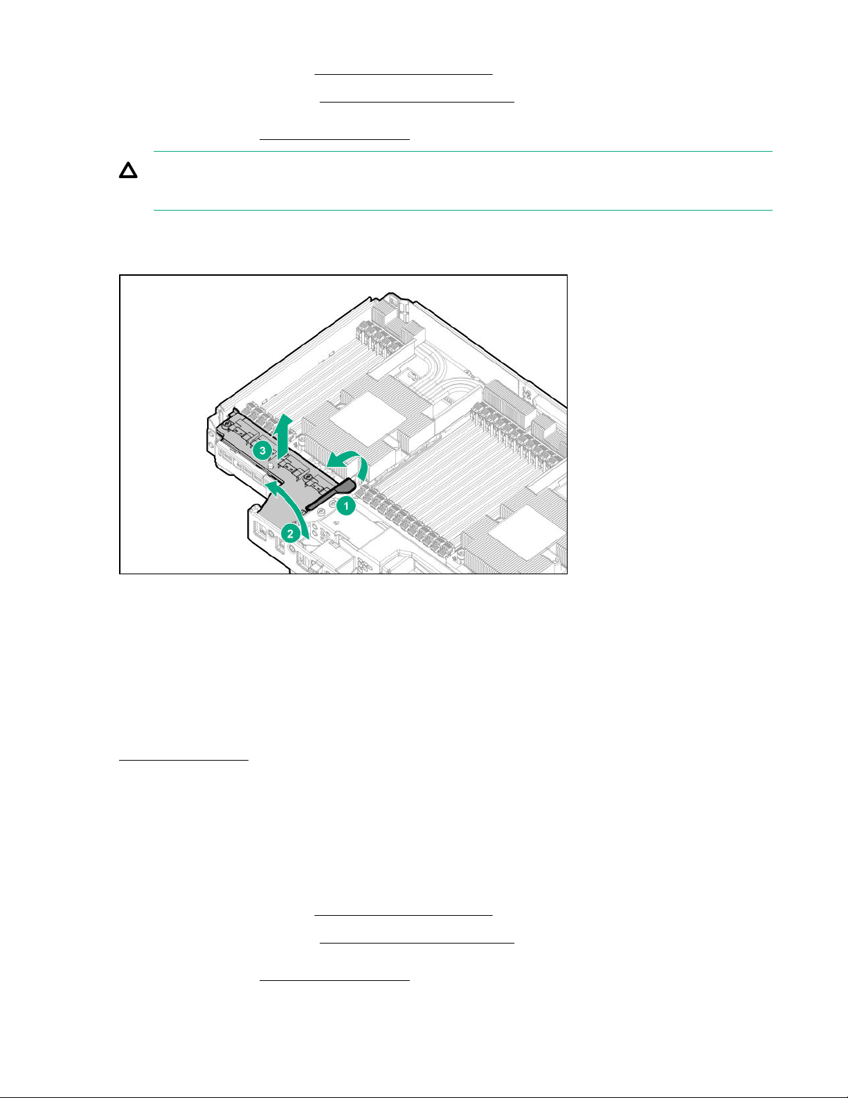
• Extend the server from the rack (Extend the server from the rack).
• Remove the server from the rack (Removing the server from the rack).
4. Remove the access panel (Removing the access panel).
CAUTION: Do not operate the server for long periods with the access panel open or removed. Operating the server
in this manner results in improper airflow and improper cooling that can lead to thermal damage.
5. Disconnect all cables connected to the mezzanine card.
6. Remove the mezzanine card.
To replace the component, reverse the removal procedure.
Removing and replacing a Systems Insight Display or Power Switch module
Procedure
Power down the server.
1.
2. Remove all power:
a. Disconnect each power cord from the power source.
b. Disconnect each power cord from the server.
3. Do one of the following:
• Extend the server from the rack (
• Remove the server from the rack (
4. Remove the access panel (Removing the access panel).
Extend the server from the rack).
Removing the server from the rack).
68
Removal and replacement procedures
Page 69
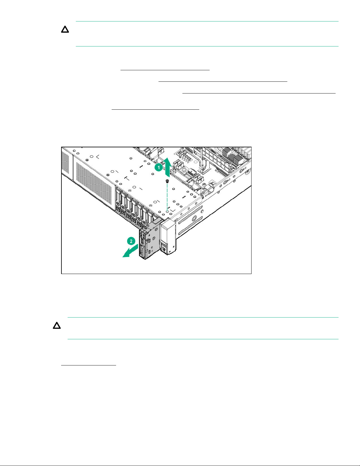
CAUTION: Do not operate the server for long periods with the access panel open or removed. Operating the server
in this manner results in improper airflow and improper cooling that can lead to thermal damage.
5. If installed, do the following:
a. Remove the air bale (Removing and replacing the air bale).
b. Remove the processor mezzanine tray (
c. Remove the CPU Mezzanine UPI performance kit (Removing and replacing the CPU Mezzanine UPI performance kit).
6. Remove the fan cage (Removing and replacing the fan cage).
7. Disconnect the cables from the system board.
8. Remove the power switch or Systems Insight Display module. Retain the T-10 screw for replacing the module.
The Systems Insight Display module is shown.
Removing and replacing the processor mezzanine tray).
To replace the component, reverse the removal procedure.
Removing and replacing a PCIe riser cage
CAUTION: To prevent damage to the server or expansion boards, power down the server and remove all AC power
cords before removing or installing the PCIe riser cage.
Procedure
Power down the server.
1.
2. Remove all power:
a. Disconnect each power cord from the power source.
b. Disconnect each power cord from the server.
3. Do one of the following:
Removal and replacement procedures
69
Page 70
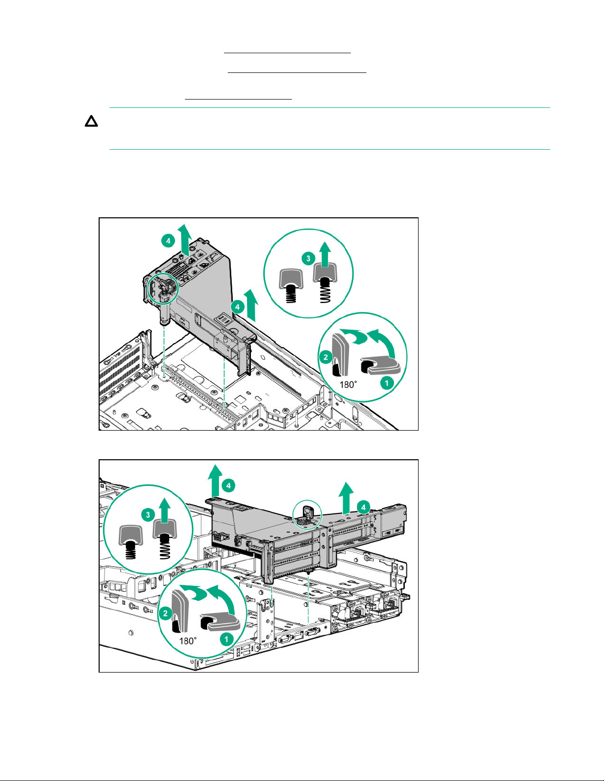
• Extend the server from the rack (Extend the server from the rack).
• Remove the server from the rack (Removing the server from the rack).
4. Remove the access panel (Removing the access panel).
CAUTION: Do not operate the server for long periods with the access panel open or removed. Operating the server
in this manner results in improper airflow and improper cooling that can lead to thermal damage.
5. Disconnect all cables attached to the expansion boards in the PCIe riser cage.
6. Remove the riser cage:
• Primary or secondary riser cage (the primary riser cage is shown):
• Tertiary riser cage:
70
Removal and replacement procedures
Page 71
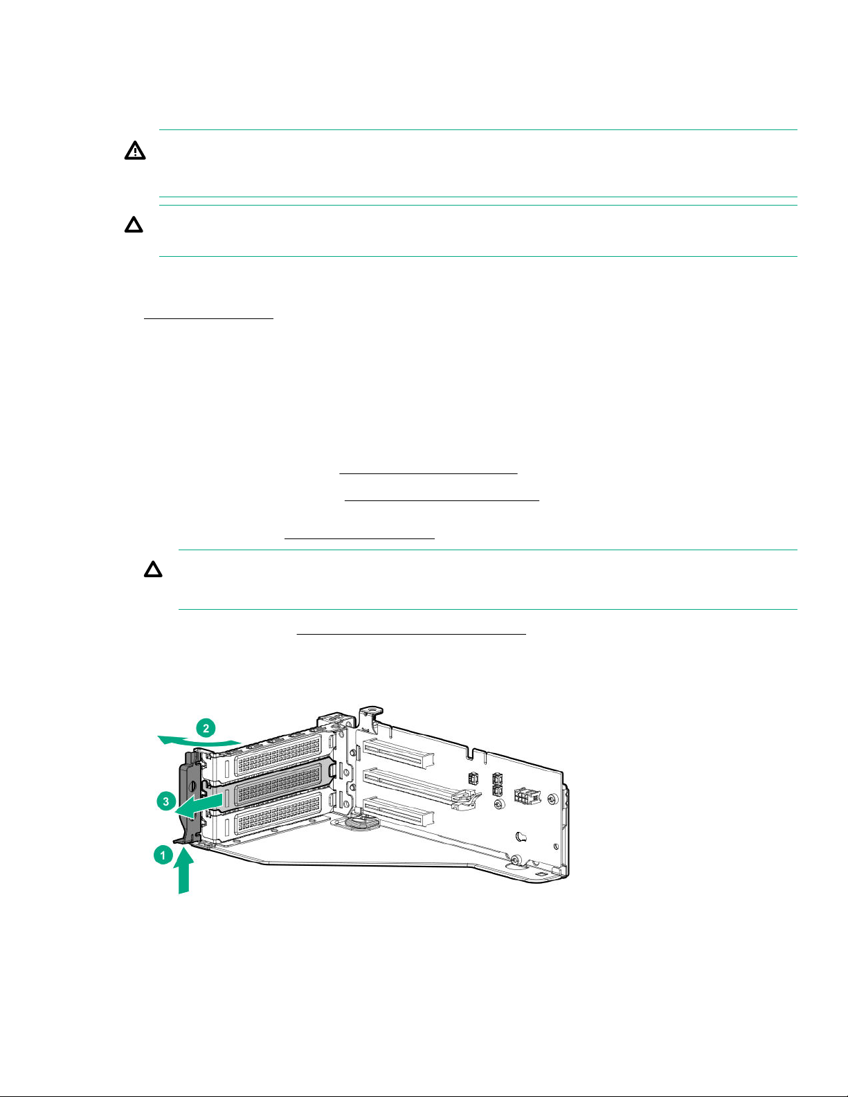
To replace the component, reverse the removal procedure.
Removing an expansion slot blank
WARNING: To reduce the risk of personal injury, electric shock, or damage to the equipment, remove the power cord to
remove power from the server. The front panel Power On/Standby button does not shut o system power. Portions of
the power supply and some internal circuitry remain active until AC power is removed.
CAUTION: To prevent improper cooling and thermal damage, do not operate the server unless all PCIe slots have either
an expansion slot cover or an expansion board installed.
Procedure
Power down the server.
1.
2. Remove all power:
a. Disconnect each power cord from the power source.
b. Disconnect each power cord from the server.
Do one of the following:
3.
• Extend the server from the rack (Extend the server from the rack).
• Remove the server from the rack (
Remove the access panel (Removing the access panel).
4.
CAUTION: Do not operate the server for long periods with the access panel open or removed. Operating the server
in this manner results in improper airflow and improper cooling that can lead to thermal damage.
Remove the PCIe riser cage (Removing and replacing a PCIe riser cage).
5.
Remove the blank.
6.
The primary PCIe riser cage is shown.
Removing the server from the rack).
To replace the component, reverse the removal procedure.
Removal and replacement procedures
71
Page 72
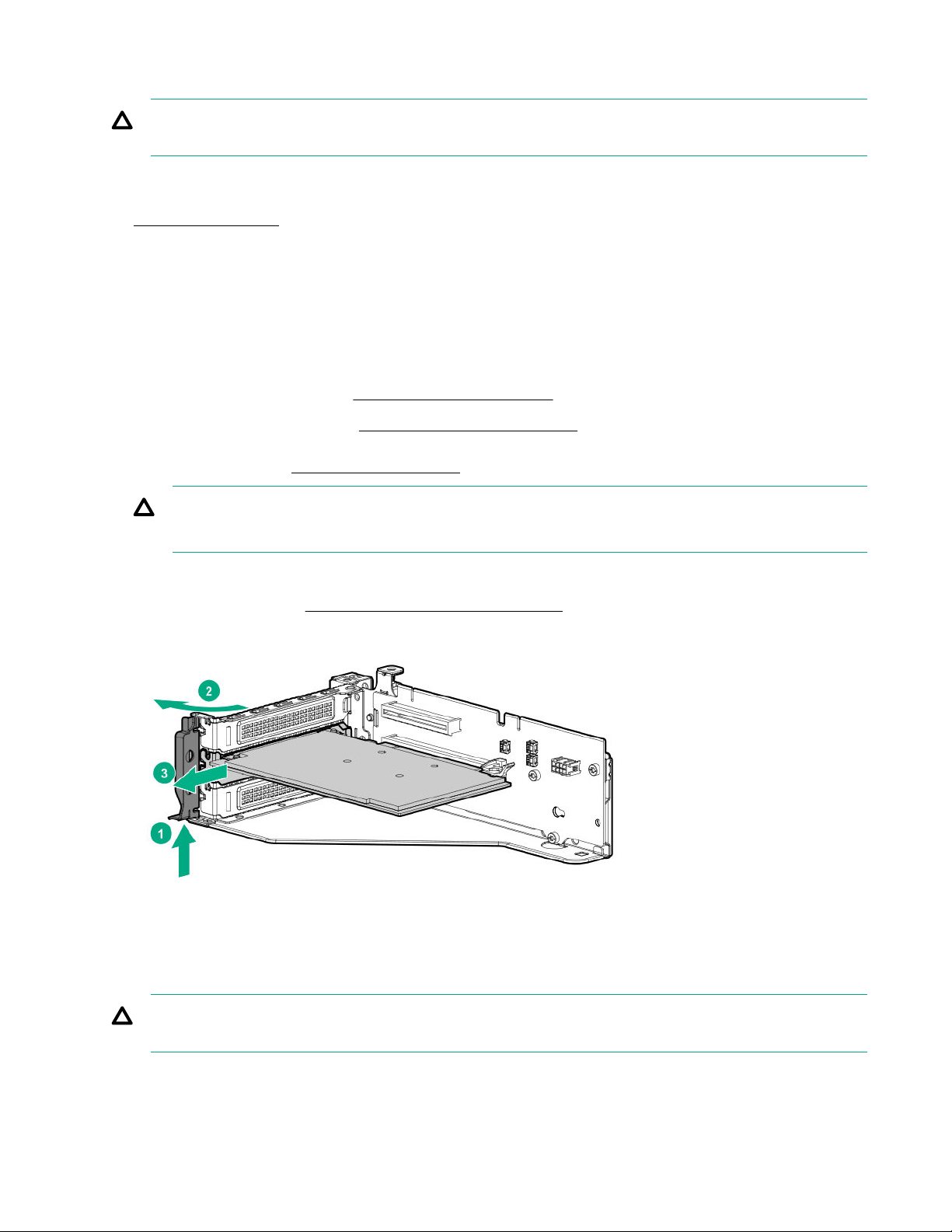
Removing and replacing an expansion board
CAUTION: To prevent damage to the server or expansion boards, power down the server and remove all AC power
cords before removing or installing the PCIe riser cage.
Procedure
Power down the server.
1.
2. Remove all power:
a. Disconnect each power cord from the power source.
b. Disconnect each power cord from the server.
3. Do one of the following:
• Extend the server from the rack (Extend the server from the rack).
• Remove the server from the rack (
Remove the access panel (Removing the access panel).
4.
CAUTION: Do not operate the server for long periods with the access panel open or removed. Operating the server
in this manner results in improper airflow and improper cooling that can lead to thermal damage.
Disconnect all cables attached to the expansion boards in the PCIe riser cage.
5.
Remove the PCIe riser cage (
6.
Remove the expansion board.
7.
Removing and replacing a PCIe riser cage).
Removing the server from the rack).
To replace the component, reverse the removal procedure.
Removing and replacing a GPU card
CAUTION: To prevent damage to the server or expansion boards, power down the server and remove all AC power
cords before removing or installing the PCIe riser cage.
72 Removal and replacement procedures
Page 73
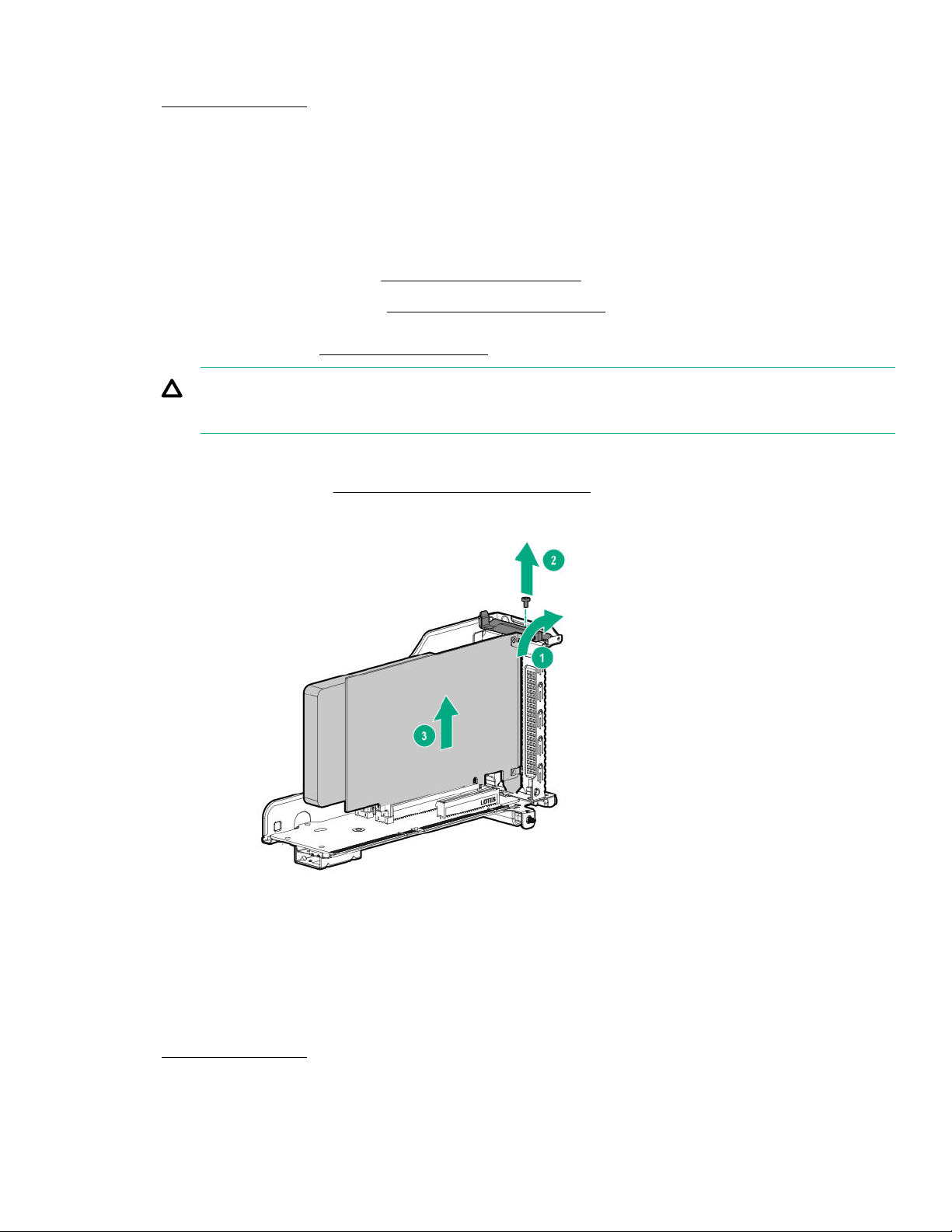
Procedure
1. Power down the server.
2. Remove all power:
a. Disconnect each power cord from the power source.
b. Disconnect each power cord from the server.
3. Do one of the following:
• Extend the server from the rack (
• Remove the server from the rack (Removing the server from the rack).
4. Remove the access panel (Removing the access panel).
CAUTION: Do not operate the server for long periods with the access panel open or removed. Operating the server
in this manner results in improper airflow and improper cooling that can lead to thermal damage.
Disconnect all cables attached to the components in the PCIe riser cage.
5.
Remove the PCIe riser cage (Removing and replacing a PCIe riser cage).
6.
Remove the GPU card.
7.
Extend the server from the rack).
To replace the component, reverse the removal procedure.
Removing and replacing the HPE 12G SAS Expander Card
Procedure
1. Power down the server.
2. Remove all power:
Removal and replacement procedures
73
Page 74
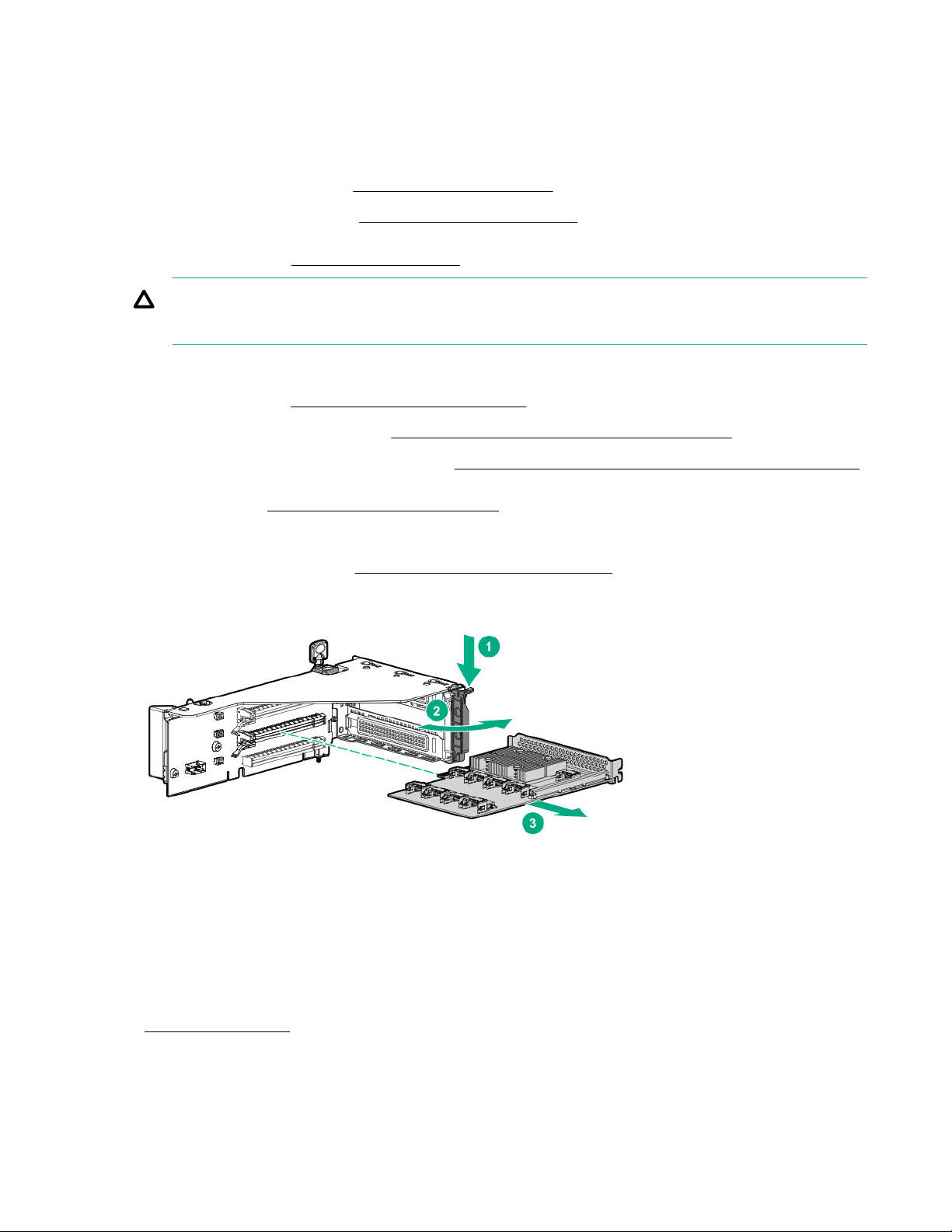
a. Disconnect each power cord from the power source.
b. Disconnect each power cord from the server.
3. Do one of the following:
• Extend the server from the rack (Extend the server from the rack).
• Remove the server from the rack (Removing the server from the rack).
4. Remove the access panel (Removing the access panel).
CAUTION: Do not operate the server for long periods with the access panel open or removed. Operating the server
in this manner results in improper airflow and improper cooling that can lead to thermal damage.
5. If installed, do the following:
a. Remove the air bale (Removing and replacing the air bale).
b. Remove the processor mezzanine tray (Removing and replacing the processor mezzanine tray).
Remove the CPU Mezzanine UPI performance kit (Removing and replacing the CPU Mezzanine UPI performance kit).
c.
Remove the fan cage (
6.
Disconnect all cables connected to the SAS expander card.
7.
Remove the primary PCIe riser cage (Removing and replacing a PCIe riser cage).
8.
Remove the SAS expander card.
9.
To replace the component, reverse the removal procedure.
Removing and replacing the fan cage).
Removing and replacing a 940QSFP 56 x16 adapter and auxiliary card
Procedure
1. Power down the server.
2. Remove all power:
74
Removal and replacement procedures
Page 75
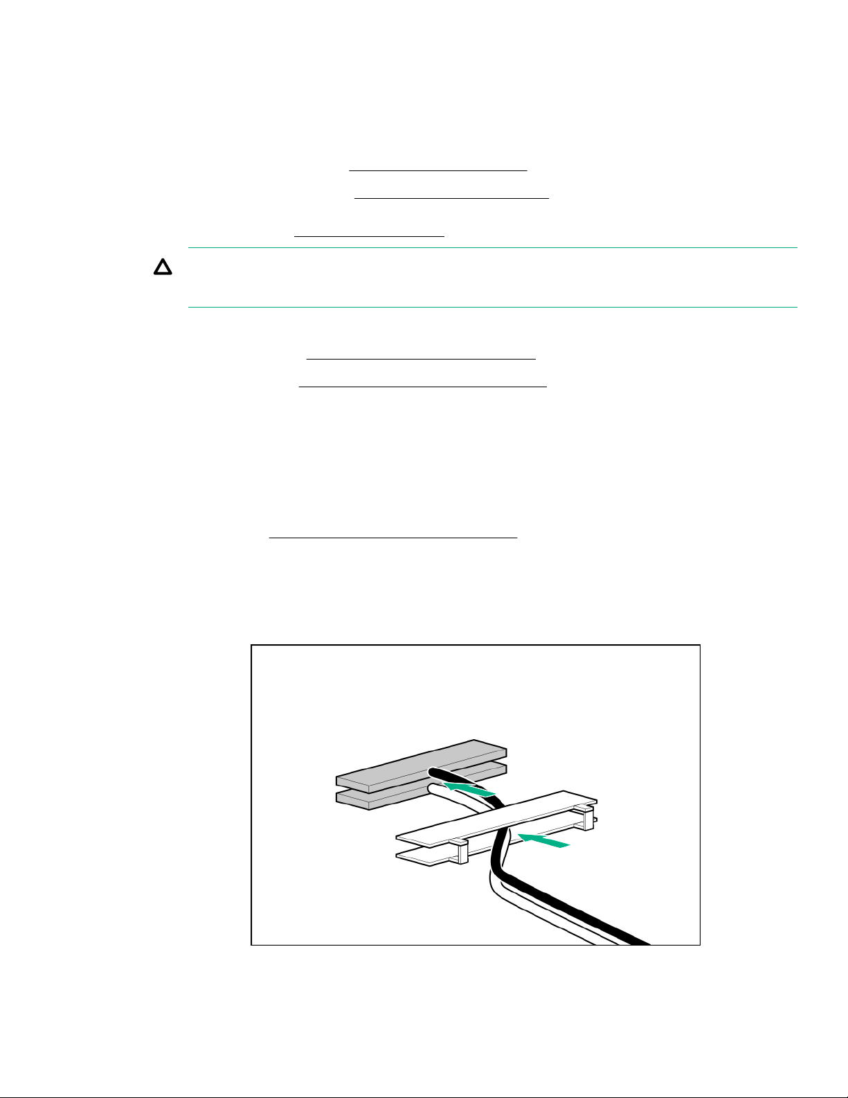
a. Disconnect each power cord from the power source.
b. Disconnect each power cord from the server.
3. Do one of the following:
• Extend the server from the rack (Extend the server from the rack).
• Remove the server from the rack (Removing the server from the rack).
4. Remove the access panel (Removing the access panel).
CAUTION: Do not operate the server for long periods with the access panel open or removed. Operating the server
in this manner results in improper airflow and improper cooling that can lead to thermal damage.
5. Disconnect all cables attached to the expansion boards in the PCIe riser cage.
6. Remove the PCIe riser cage (Removing and replacing a PCIe riser cage).
7. Remove the auxiliary card (
Disconnect the cables to the auxiliary card:
8.
Open the retention clip and slide it away from the connectors.
a.
Gently pull up the top corner of the cable latch door.
b.
Disconnect the card cables.
c.
Remove the adapter (
9.
Disconnect the cables to the adapter.
10.
To replace the component:
Thread the adapter end of the auxiliary card cables through one of the retention clips provided with the installation kit.
1.
Removing and replacing an expansion board).
Removing and replacing an expansion board).
2. Open the cable latch door, connect the auxiliary card cables to the adapter ports so that the golden side of the cable
connector is on the top, and then close the cable latch door.
Removal and replacement procedures
75
Page 76
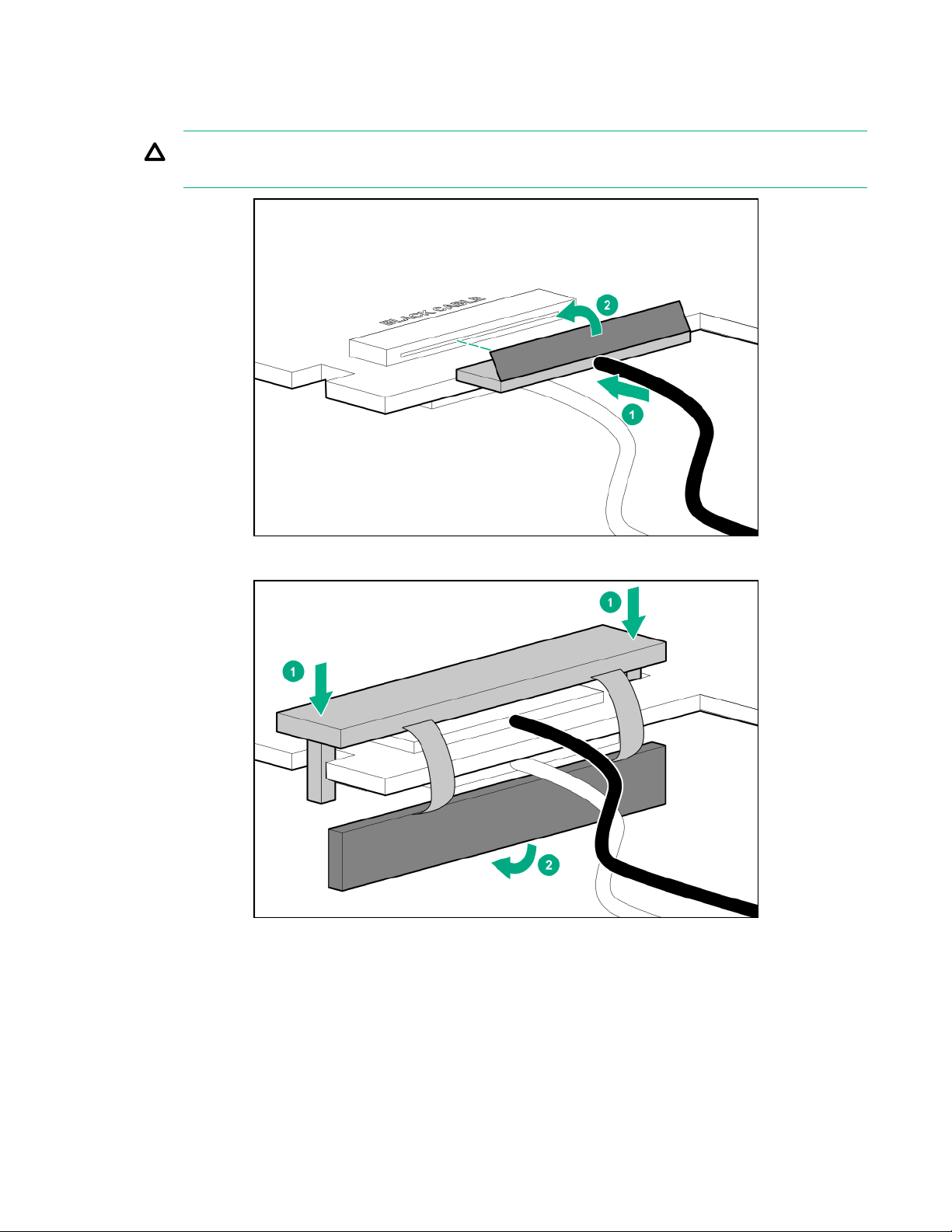
The white and black cables from the auxiliary card connect to the expansion board ports labeled WHITE CABLE and
BLACK CABLE, respectively.
The cable latch door must be open when connecting the cables.
CAUTION: The connector pins are fragile and easily damaged. To avoid damaging the connector pins, do not use
excessive force when connecting the cables.
Install the retention clip.
3.
4. Thread the auxiliary cables through the second retention clip.
5. Connect the auxiliary cables to the auxiliary card.
6. Confirm that the orientation of the cables is correct.
76
Removal and replacement procedures
Page 77
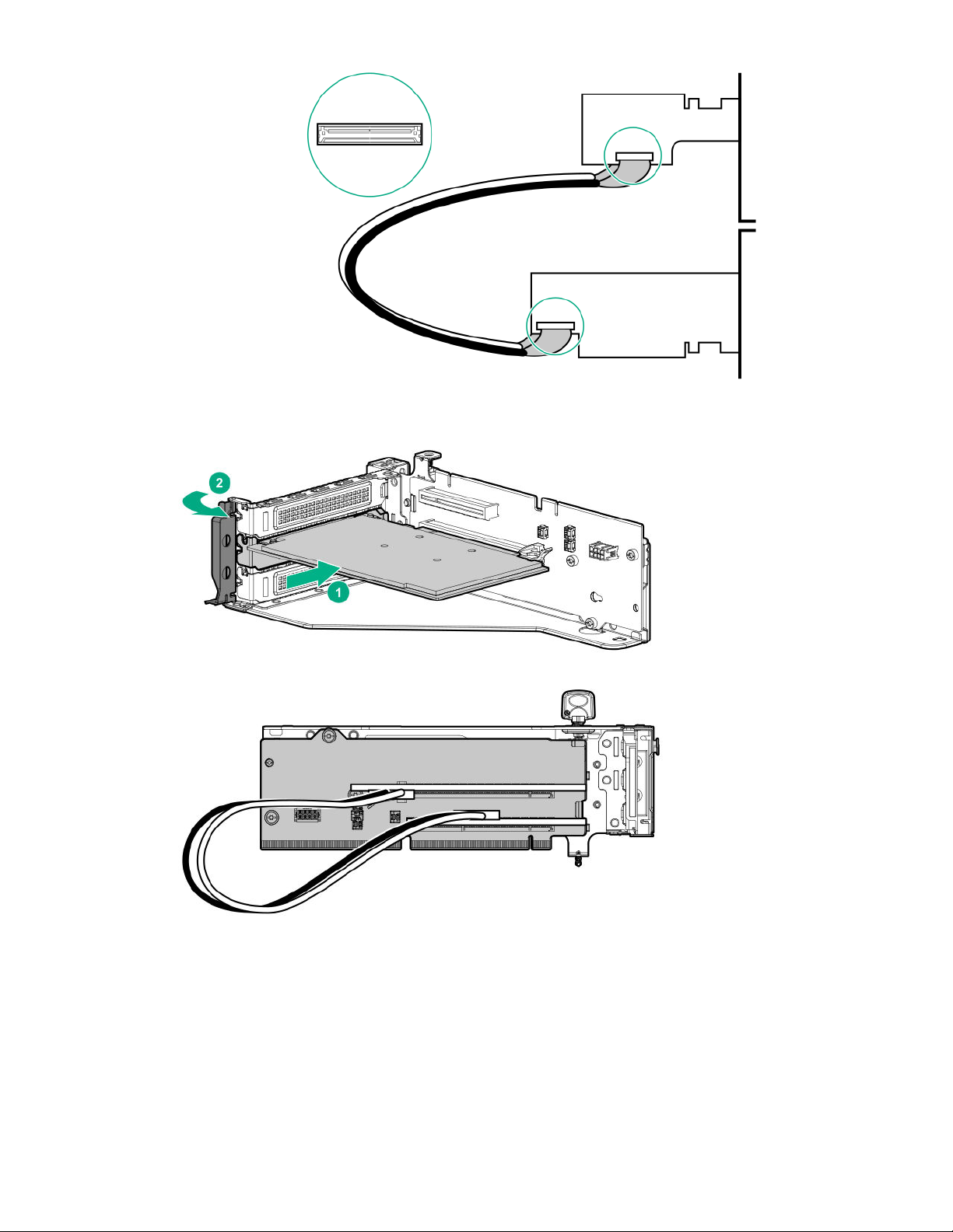
7. Install the adapter and auxiliary cards into x16 slots.
8. Install the riser cages into the server, and observe the following cable routing:
Primary riser cage
Removal and replacement procedures
77
Page 78
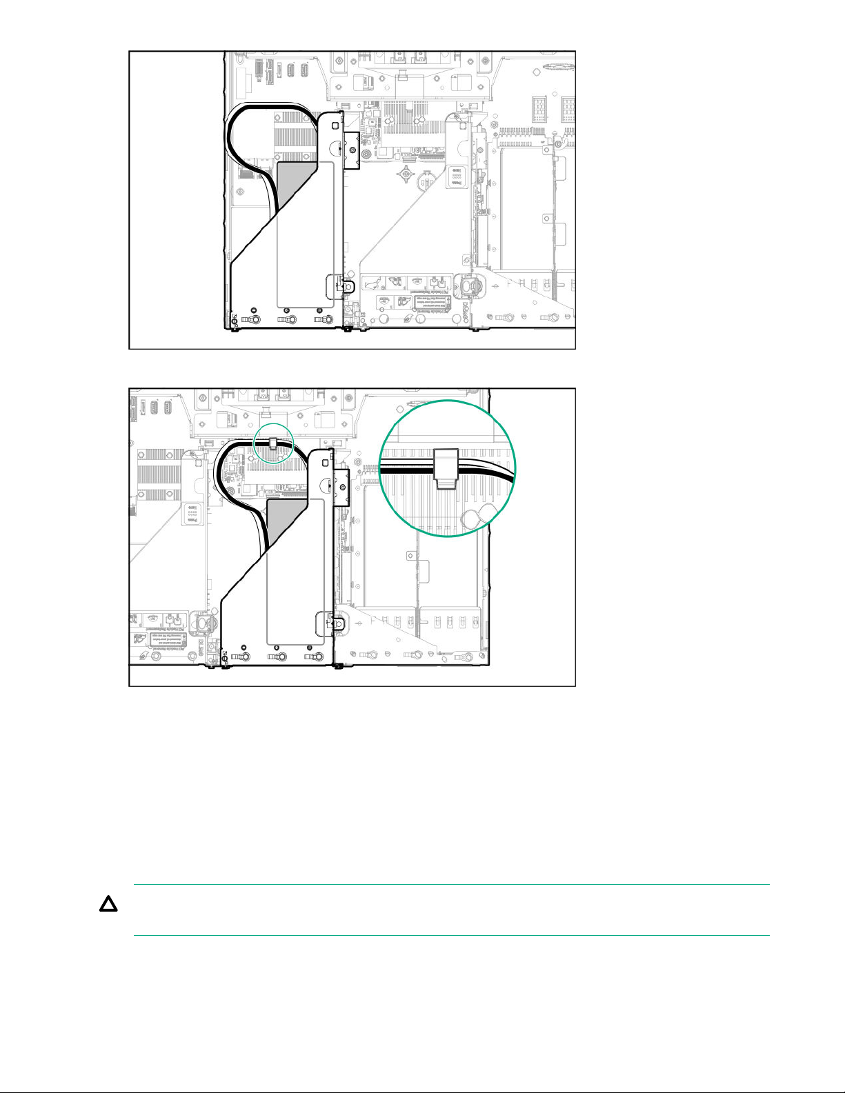
Secondary riser cage
Install the access panel.
9.
Connect each power cord to the server.
10.
11. Connect each power cord to the power source.
12. Power up the server.
Removing and replacing a riser board
CAUTION: To prevent damage to the server or expansion boards, power down the server and remove all AC power
cords before removing or installing the PCIe riser cage.
78 Removal and replacement procedures
Page 79
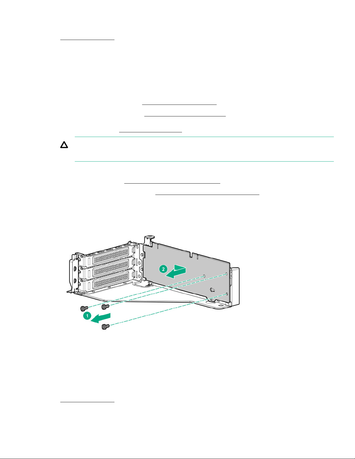
Procedure
1. Power down the server.
2. Remove all power:
a. Disconnect each power cord from the power source.
b. Disconnect each power cord from the server.
3. Do one of the following:
• Extend the server from the rack (
• Remove the server from the rack (Removing the server from the rack).
4. Remove the access panel (Removing the access panel).
CAUTION: Do not operate the server for long periods with the access panel open or removed. Operating the server
in this manner results in improper airflow and improper cooling that can lead to thermal damage.
Disconnect all cables attached to the expansion boards in the PCIe riser cage.
5.
Remove the PCIe riser cage (Removing and replacing a PCIe riser cage).
6.
If installed, remove the expansion boards. (
7.
Remove the riser board installed in the riser cage.
8.
The primary PCIe riser cage is shown. Your riser board might appear dierent.
Extend the server from the rack).
Removing and replacing an expansion board).
To replace the component, reverse the removal procedure.
Removing and replacing the FlexibleLOM
Procedure
1. Power down the server.
2. Remove all power:
Removal and replacement procedures
79
Page 80
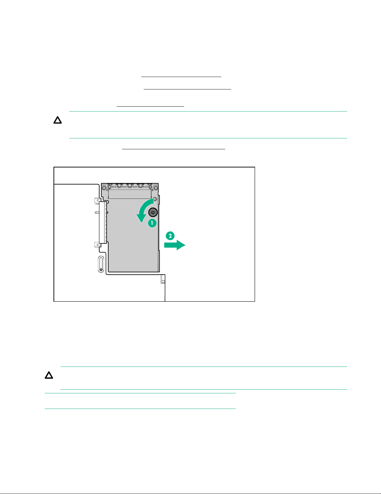
a. Disconnect each power cord from the power source.
b. Disconnect each power cord from the server.
3. Do one of the following:
• Extend the server from the rack (Extend the server from the rack).
• Remove the server from the rack (Removing the server from the rack).
4. Remove the access panel (Removing the access panel).
CAUTION: Do not operate the server for long periods with the access panel open or removed. Operating the server
in this manner results in improper airflow and improper cooling that can lead to thermal damage.
5. Remove the PCIe riser cage (Removing and replacing a PCIe riser cage).
6. Remove the FlexibleLOM.
To replace the component, reverse the removal procedure.
Removing and replacing an energy pack
This server supports two HPE Smart Storage batteries or one HPE Smart Storage Hybrid Capacitor. To support P-series Smart
Array controllers, an energy pack must be installed.
CAUTION: This server does not support mixing of the HPE Smart Storage batteries and the HPE Smart Storage Hybrid
Capacitor.
NOTE: To support NVDIMMs, you must install two HPE Smart Storage batteries.
80 Removal and replacement procedures
Page 81
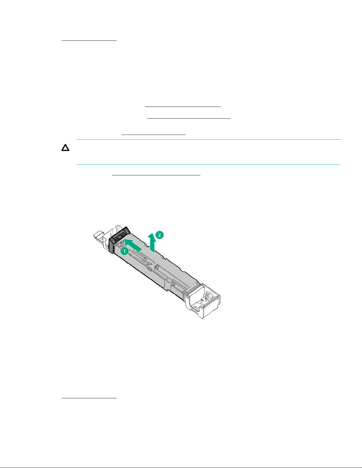
Procedure
1. Power down the server.
2. Remove all power:
a. Disconnect each power cord from the power source.
b. Disconnect each power cord from the server.
3. Do one of the following:
• Extend the server from the rack (
• Remove the server from the rack (Removing the server from the rack).
4. Remove the access panel (Removing the access panel).
CAUTION: Do not operate the server for long periods with the access panel open or removed. Operating the server
in this manner results in improper airflow and improper cooling that can lead to thermal damage.
Remove the fan cage (Removing and replacing the fan cage).
5.
Disconnect the energy pack cable from the system board.
6.
Remove the energy pack.
7.
Extend the server from the rack).
To replace the component, reverse the removal procedure.
Removing and replacing an eight-bay SFF HDD cage
Procedure
1. Power down the server.
2. Remove all power:
Removal and replacement procedures
81
Page 82
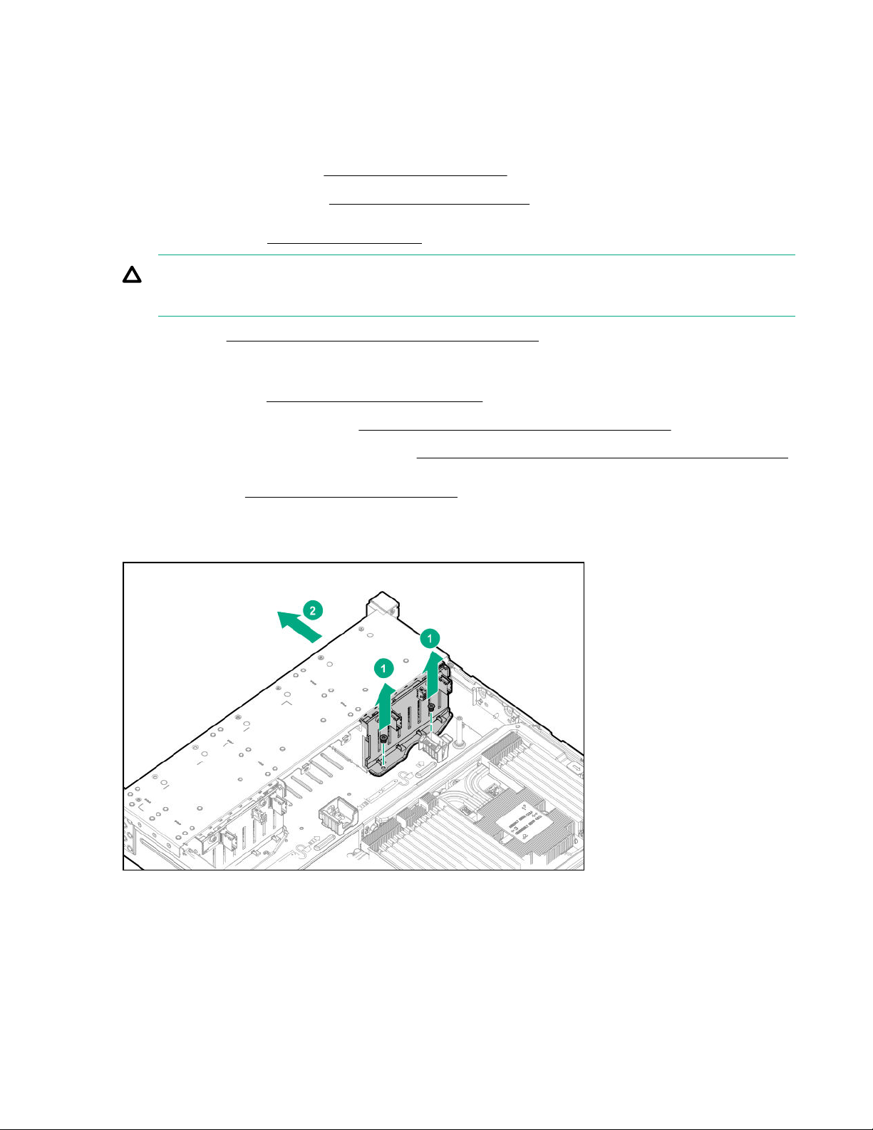
a. Disconnect each power cord from the power source.
b. Disconnect each power cord from the server.
3. Do one of the following:
• Extend the server from the rack (Extend the server from the rack).
• Remove the server from the rack (Removing the server from the rack).
4. Remove the access panel (Removing the access panel).
CAUTION: Do not operate the server for long periods with the access panel open or removed. Operating the server
in this manner results in improper airflow and improper cooling that can lead to thermal damage.
5. Remove all drives (Removing and replacing a hot-plug SAS or SATA drive).
6. If installed, do the following:
a. Remove the air bale (Removing and replacing the air bale).
Remove the processor mezzanine tray (Removing and replacing the processor mezzanine tray).
b.
Remove the CPU Mezzanine UPI performance kit (
c.
Remove the fan cage (Removing and replacing the fan cage).
7.
Disconnect all cables from the drive backplane.
8.
Remove the drive cage.
9.
Removing and replacing the CPU Mezzanine UPI performance kit).
To replace the component, reverse the removal procedure.
82
Removal and replacement procedures
Page 83
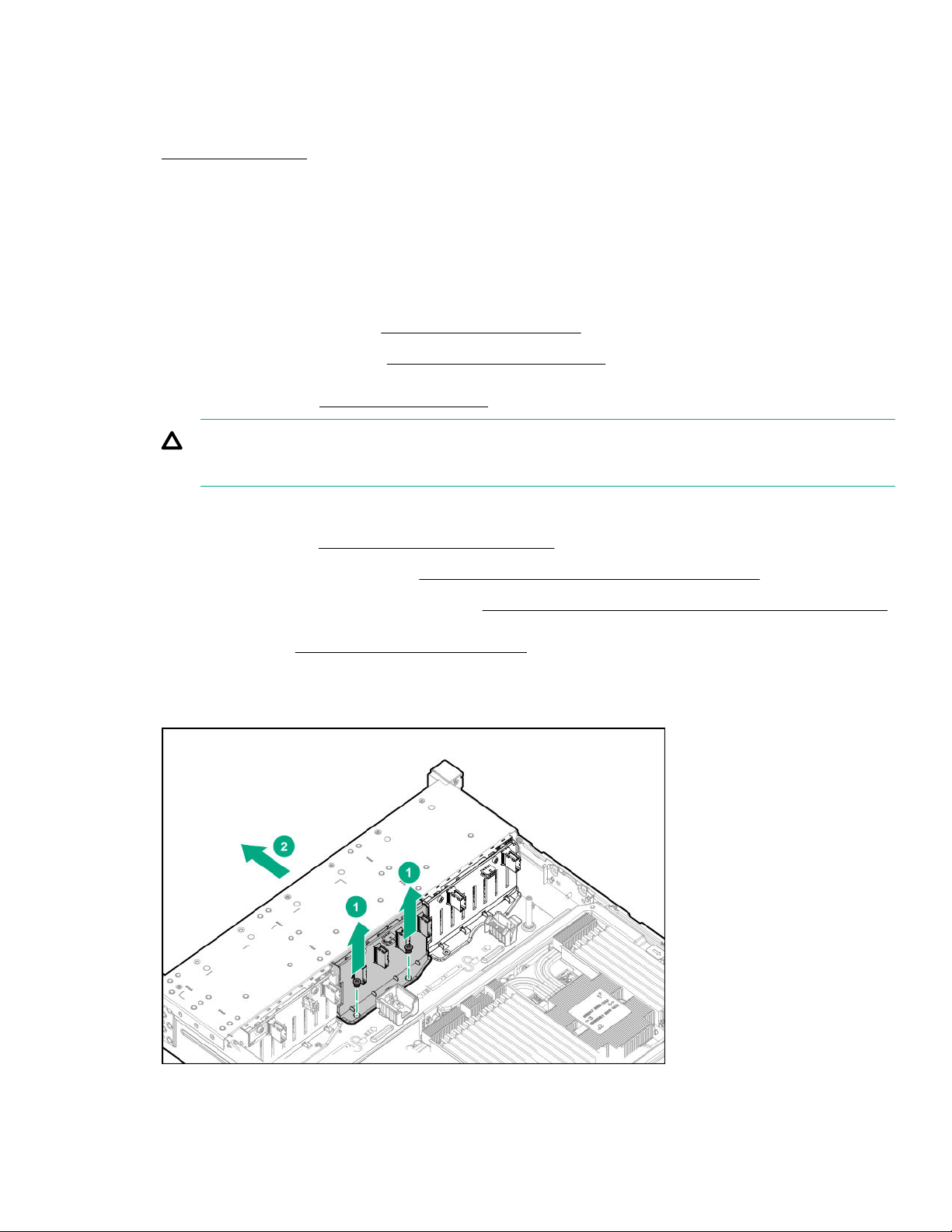
Removing and replacing an eight-bay NVMe SSD drive cage
Procedure
1. Power down the server.
2. Remove all power:
a. Disconnect each power cord from the power source.
b. Disconnect each power cord from the server.
3. Do one of the following:
• Extend the server from the rack (
• Remove the server from the rack (Removing the server from the rack).
4. Remove the access panel (
CAUTION: Do not operate the server for long periods with the access panel open or removed. Operating the server
in this manner results in improper airflow and improper cooling that can lead to thermal damage.
If installed, do the following:
5.
Remove the air bale (Removing and replacing the air bale).
a.
Remove the processor mezzanine tray (
b.
Remove the CPU Mezzanine UPI performance kit (Removing and replacing the CPU Mezzanine UPI performance kit).
c.
Remove the fan cage (Removing and replacing the fan cage).
6.
Disconnect all cables from the drive backplane.
7.
Remove the drive cage.
8.
Removing the access panel).
Extend the server from the rack).
Removing and replacing the processor mezzanine tray).
To replace the component, reverse the removal procedure.
Removal and replacement procedures
83
Page 84
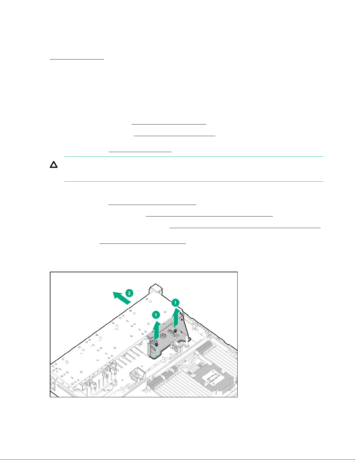
Removing and replacing a universal media bay
Procedure
1. Power down the server.
2. Remove all power:
a. Disconnect each power cord from the power source.
b. Disconnect each power cord from the server.
3. Do one of the following:
• Extend the server from the rack (
• Remove the server from the rack (Removing the server from the rack).
4. Remove the access panel (
CAUTION: Do not operate the server for long periods with the access panel open or removed. Operating the server
in this manner results in improper airflow and improper cooling that can lead to thermal damage.
If installed, do the following:
5.
Remove the air bale (Removing and replacing the air bale).
a.
Remove the processor mezzanine tray (
b.
Remove the CPU Mezzanine UPI performance kit (Removing and replacing the CPU Mezzanine UPI performance kit).
c.
Remove the fan cage (Removing and replacing the fan cage).
6.
Disconnect all cables from the universal media bay.
7.
Remove the universal media bay.
8.
Removing the access panel).
Extend the server from the rack).
Removing and replacing the processor mezzanine tray).
To replace the component, reverse the removal procedure.
84
Removal and replacement procedures
Page 85
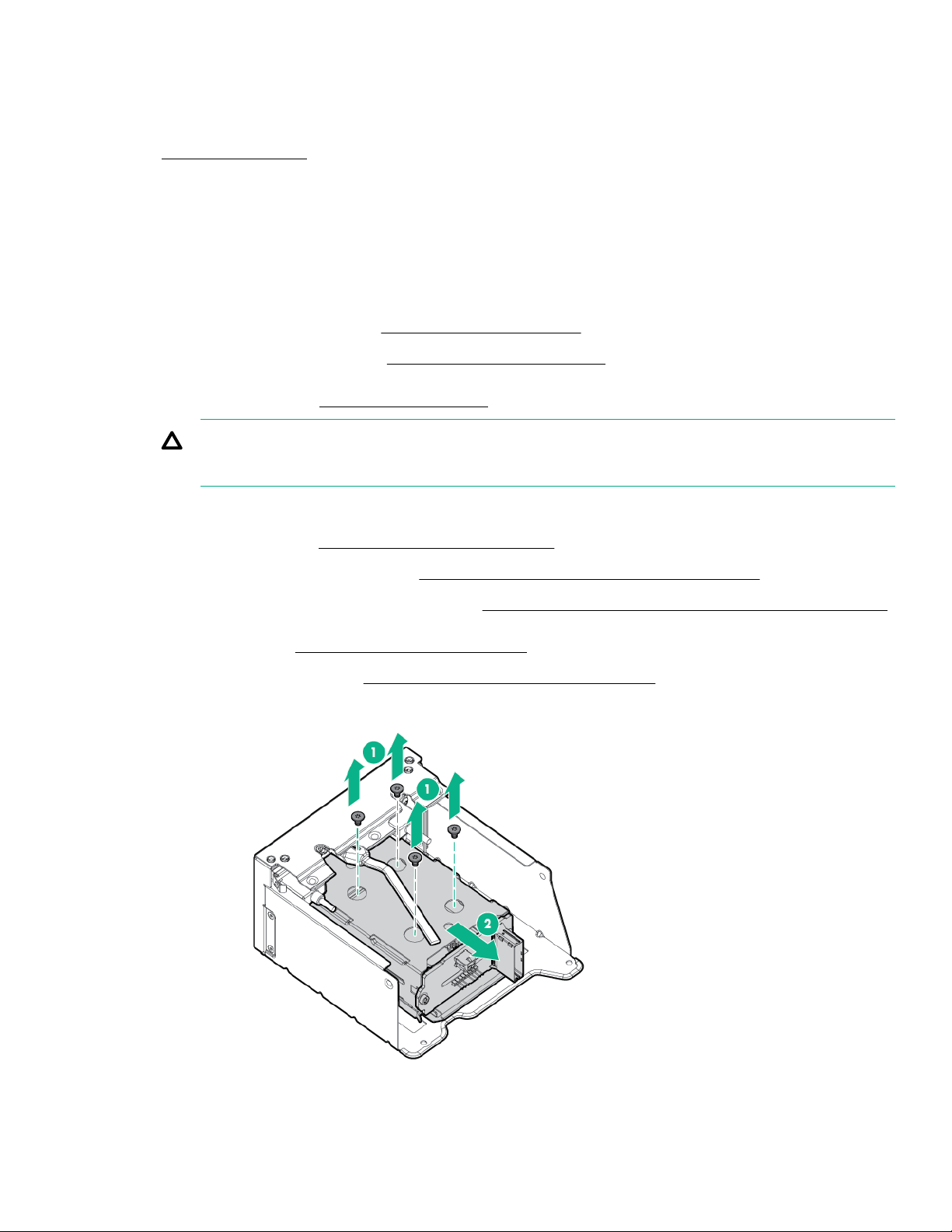
Removing and replacing a two-bay SFF drive cage
Procedure
1. Power down the server.
2. Remove all power:
a. Disconnect each power cord from the power source.
b. Disconnect each power cord from the server.
3. Do one of the following:
• Extend the server from the rack (
• Remove the server from the rack (Removing the server from the rack).
4. Remove the access panel (
CAUTION: Do not operate the server for long periods with the access panel open or removed. Operating the server
in this manner results in improper airflow and improper cooling that can lead to thermal damage.
If installed, do the following:
5.
Remove the air bale (Removing and replacing the air bale).
a.
Remove the processor mezzanine tray (
b.
Remove the CPU Mezzanine UPI performance kit (Removing and replacing the CPU Mezzanine UPI performance kit).
c.
Remove the fan cage (Removing and replacing the fan cage).
6.
Remove the universal media bay (
7.
Remove the drive cage.
8.
Removing the access panel).
Extend the server from the rack).
Removing and replacing the processor mezzanine tray).
Removing and replacing a universal media bay).
To replace the component, reverse the removal procedure.
Removal and replacement procedures
85
Page 86
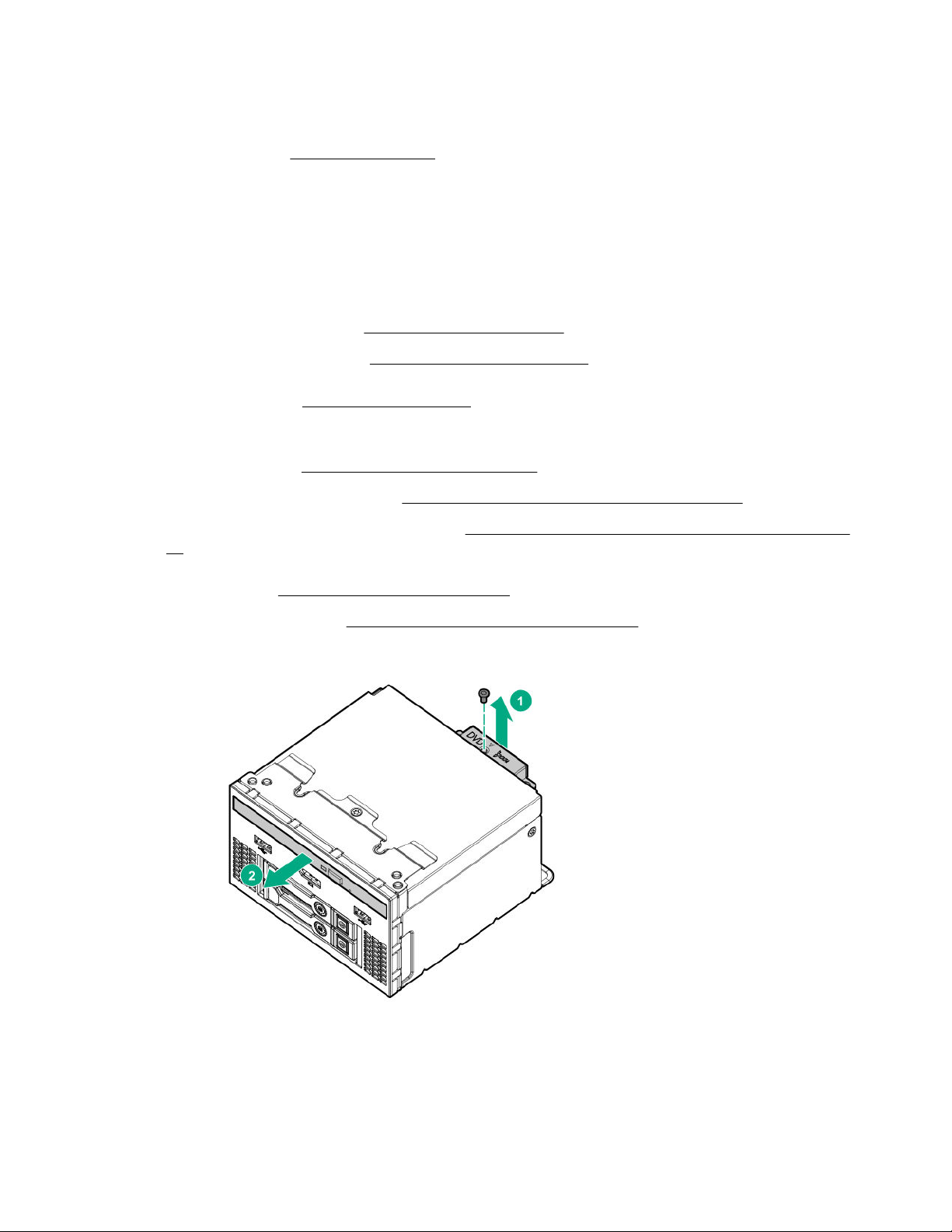
Removing and replacing the optical drive
Procedure
1. Power down the server (Power down the server).
2. Remove all power:
a. Disconnect each power cord from the power source.
b. Disconnect each power cord from the server.
3. Do one of the following:
• Extend the server from the rack (
• Remove the server from the rack (Removing the server from the rack).
4. Remove the access panel (
5. If installed, do the following:
Remove the air
a.
Remove the processor mezzanine tray (Removing and replacing the processor mezzanine tray).
b.
Remove the CPU Mezzanine UPI performance kit (
c.
kit).
Remove the fan cage (Removing and replacing the fan cage).
6.
Remove the universal media bay (
7.
Remove the optical drive.
8.
Removing the access panel).
bale (Removing and replacing the air bale).
Extend the server from the rack).
Removing and replacing the CPU Mezzanine UPI performance
Removing and replacing a universal media bay).
9. Remove the optical drive bracket, for use with the replacement optical drive.
86
Removal and replacement procedures
Page 87
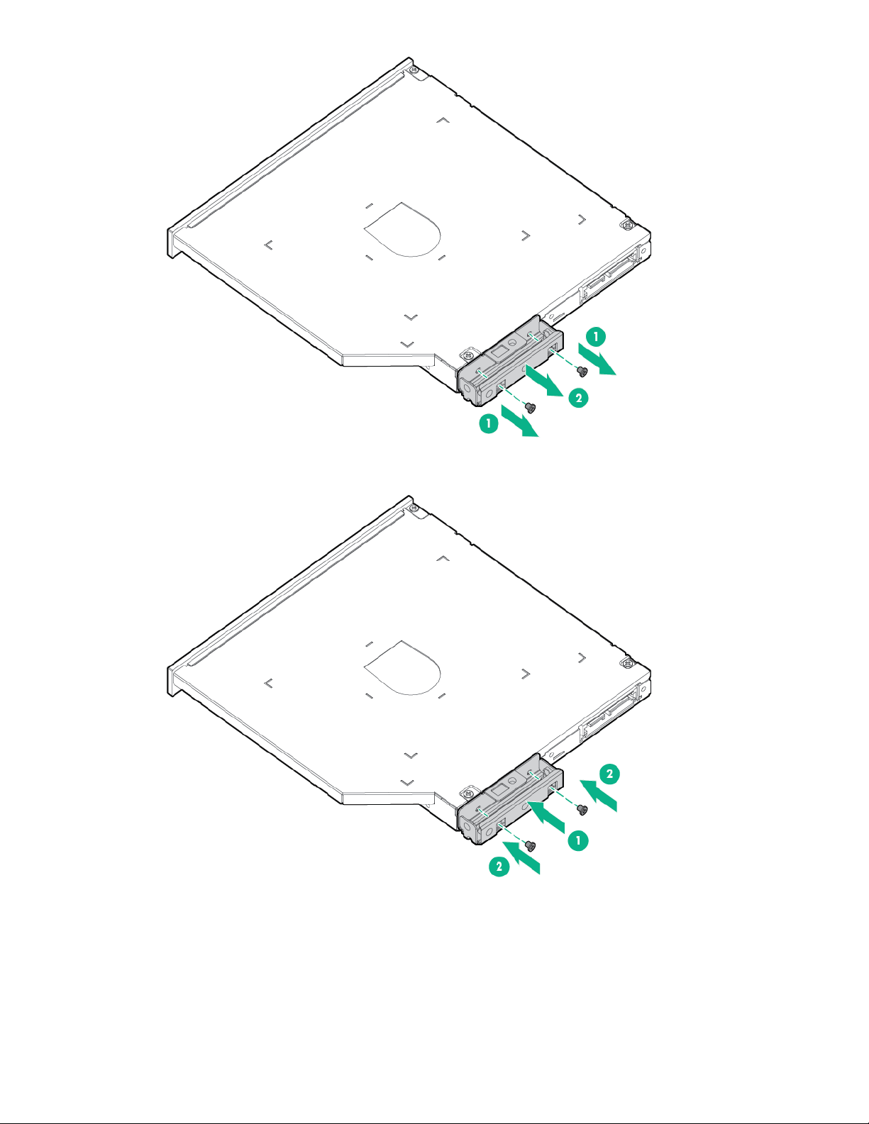
Before replacing the component, install the optical drive bracket, retained from the optical drive you are replacing.
10.
To replace the component, reverse the removal procedure.
Removal and replacement procedures
87
Page 88
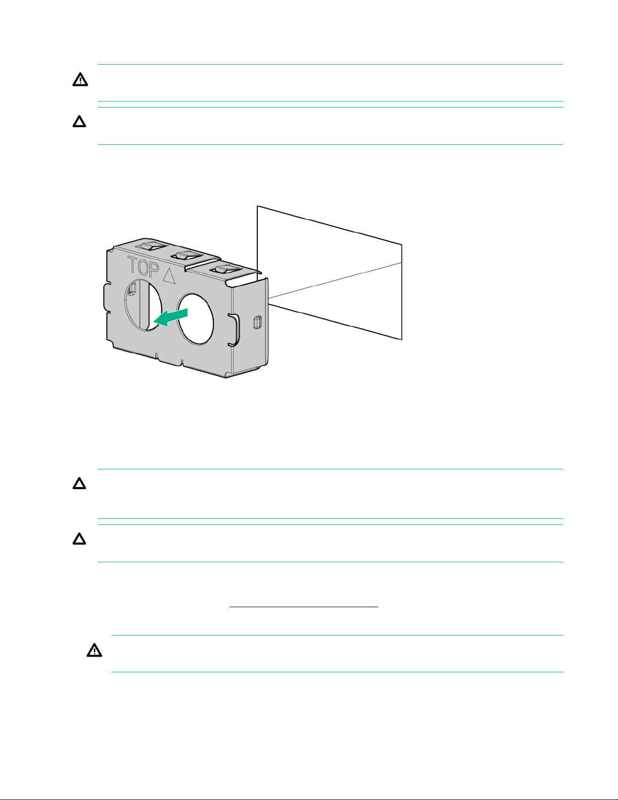
Removing and replacing a power supply blank
WARNING: To reduce the risk of personal injury from hot surfaces, allow the power supply or power supply blank to cool
before touching it.
CAUTION: To prevent improper cooling and thermal damage, do not operate the server unless all bays are populated
with either a component or a blank.
Procedure
1. Remove the power supply blank.
Immediately install the replacement power supply blank spare.
2.
Removing and replacing a power supply
CAUTION: All power supplies installed in the server must have the same output power capacity. Verify that all power
supplies have the same part number and label color. The system becomes unstable and may shut down when it detects
mismatched power supplies.
CAUTION: To prevent improper cooling and thermal damage, do not operate the server unless all device bays are
populated with either a component or a blank.
Procedure
1. Release the cable management arm (
2. Remove the power supply.
WARNING: To reduce the risk of personal injury from hot surfaces, allow the drives and the internal system
components to cool before touching them.
Release the cable management arm ).
88 Removal and replacement procedures
Page 89
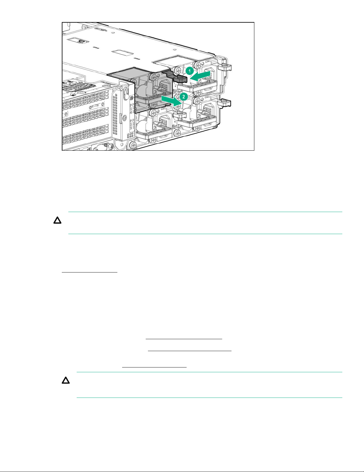
To replace the component, reverse the removal procedure.
Removing and replacing a Smart Array controller
Removing and replacing a type-a controller
CAUTION: Hewlett Packard Enterprise recommends performing a backup of all server data before installing or removing
a controller or adapter.
Procedure
Back up all server data.
1.
Power down the server.
2.
Remove all power:
3.
Disconnect each power cord from the power source.
a.
Disconnect each power cord from the server.
b.
Do one of the following:
4.
• Extend the server from the rack (
• Remove the server from the rack (Removing the server from the rack).
5. Remove the access panel (
CAUTION: Do not operate the server for long periods with the access panel open or removed. Operating the server
in this manner results in improper airflow and improper cooling that can lead to thermal damage.
6. If installed, do the following:
Removing the access panel).
Extend the server from the rack).
Removal and replacement procedures
89
Page 90
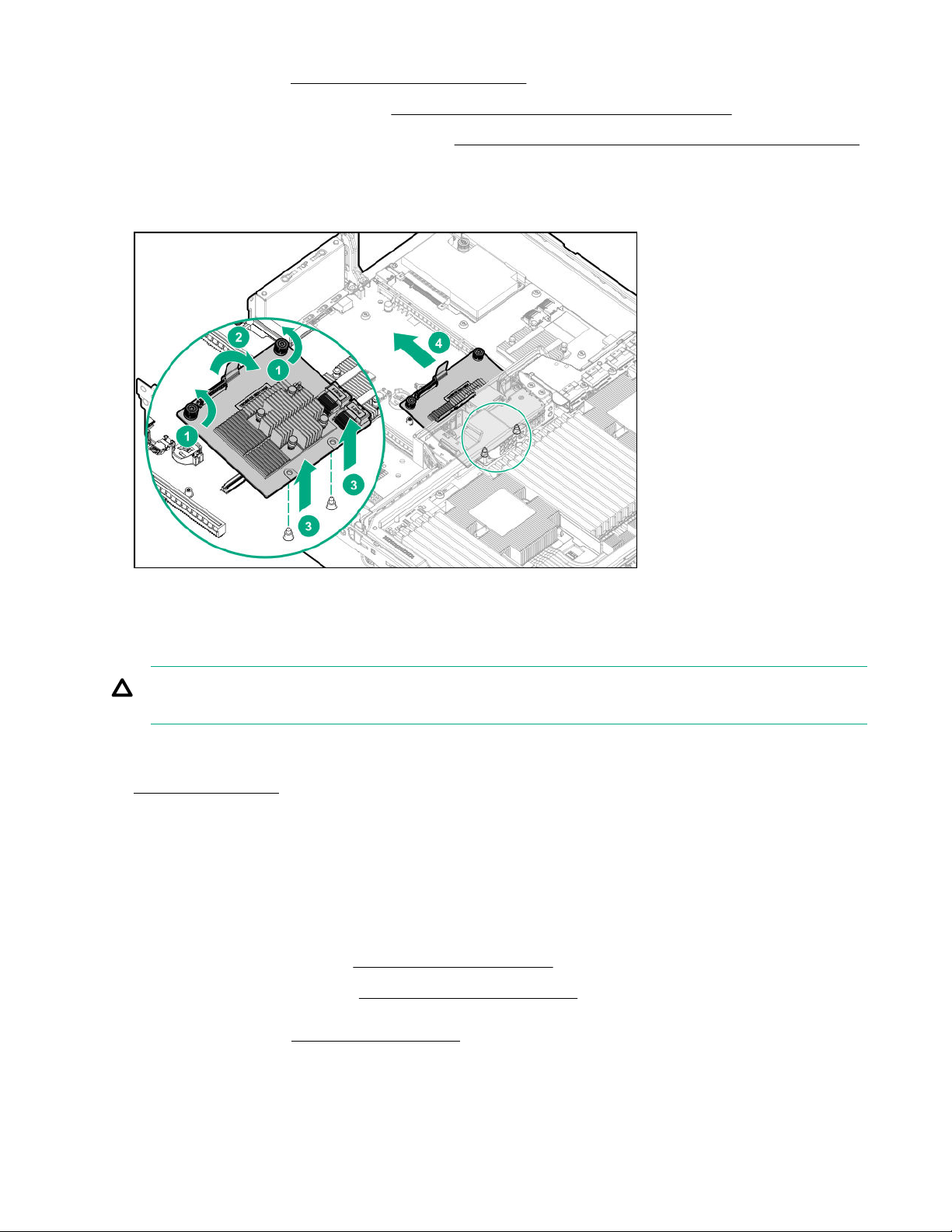
a. Remove the air bale (Removing and replacing the air bale).
b. Remove the processor mezzanine tray (Removing and replacing the processor mezzanine tray).
c. Remove the CPU Mezzanine UPI performance kit (Removing and replacing the CPU Mezzanine UPI performance kit).
7. Disconnect any cables connected to the controller.
8. Remove the controller.
To replace the component, reverse the removal procedure.
Removing and replacing a type-p controller
CAUTION: To prevent damage to the server or expansion boards, power down the server and remove all AC power
cords before removing or installing the PCIe riser cage.
Procedure
Power down the server.
1.
Remove all power:
2.
a. Disconnect each power cord from the power source.
b. Disconnect each power cord from the server.
3. Do one of the following:
• Extend the server from the rack (Extend the server from the rack).
• Remove the server from the rack (Removing the server from the rack).
4. Remove the access panel (
Removing the access panel).
90
Removal and replacement procedures
Page 91
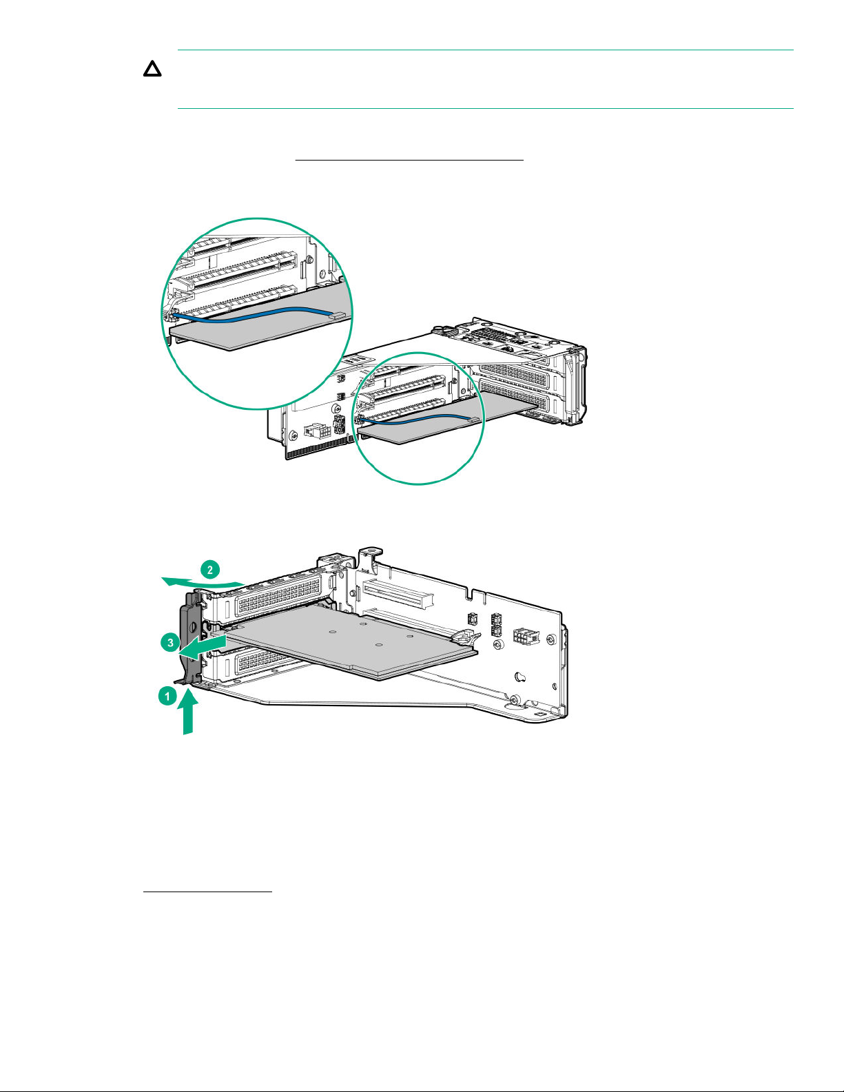
CAUTION: Do not operate the server for long periods with the access panel open or removed. Operating the server
in this manner results in improper airflow and improper cooling that can lead to thermal damage.
5. Disconnect the SAS cables.
6. Remove the PCIe riser cage (
7. Disconnect the controller backup power cable from the controller backup power connector on the riser board.
Remove the type-p controller.
8.
Removing and replacing a PCIe riser cage).
To replace the component, reverse the removal procedure.
Removing and replacing an intrusion detection switch
Procedure
Power down the server.
1.
2. Remove all power:
Removal and replacement procedures
91
Page 92
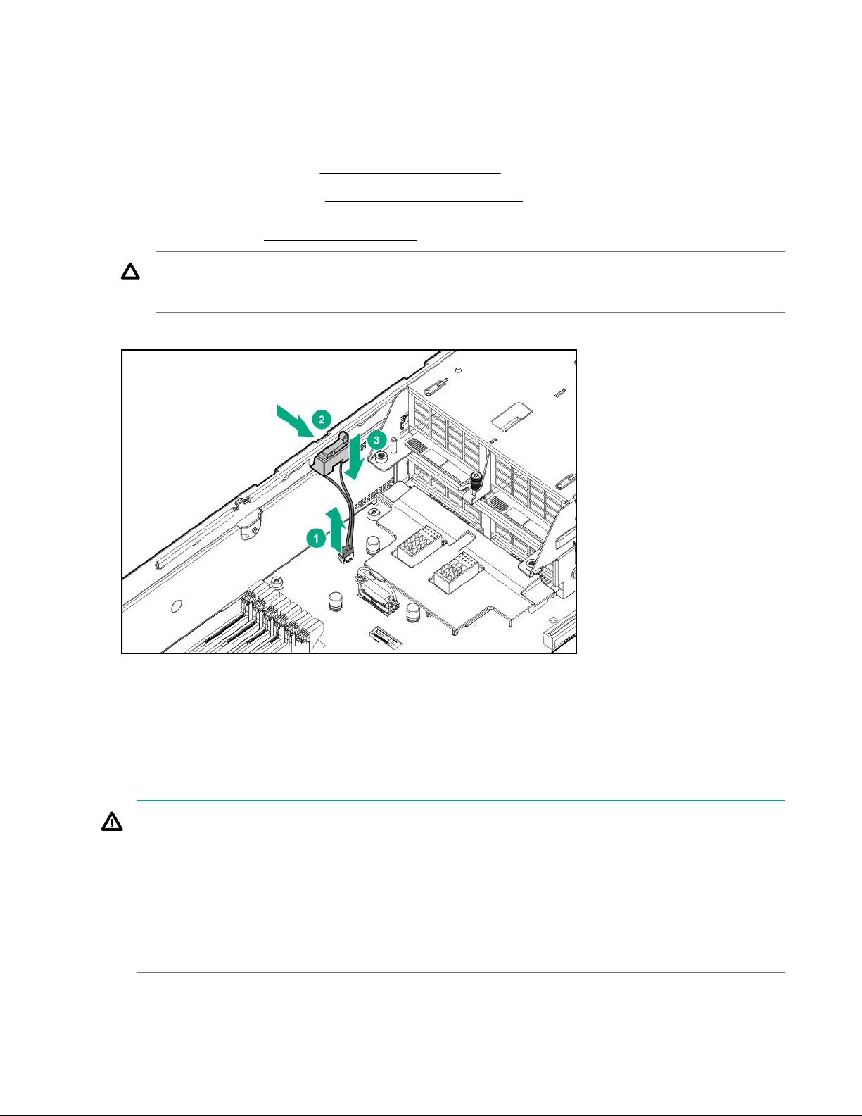
a. Disconnect each power cord from the power source.
b. Disconnect each power cord from the server.
3. Do one of the following:
• Extend the server from the rack (Extend the server from the rack).
• Remove the server from the rack (Removing the server from the rack).
4. Remove the access panel (Removing the access panel).
CAUTION: Do not operate the server for long periods with the access panel open or removed. Operating the server
in this manner results in improper airflow and improper cooling that can lead to thermal damage.
5. Remove the intrusion detection switch.
To replace the component, reverse the removal procedure.
Replacing the system battery
The system battery provides power to the internal clock. If the server no longer automatically displays the correct date and
time, you might need to replace the system battery.
WARNING: The computer contains an internal lithium manganese dioxide, a vanadium pentoxide, or an alkaline battery
pack. A risk of fire and burns exists if the battery pack is not properly handled. To reduce the risk of personal injury:
• Do not attempt to recharge the battery.
• Do not expose the battery to temperatures higher than 60°C (140°F).
• Do not disassemble, crush, puncture, short external contacts, or dispose of in fire or water.
• Replace only with the spare designated for this product.
92 Removal and replacement procedures
Page 93
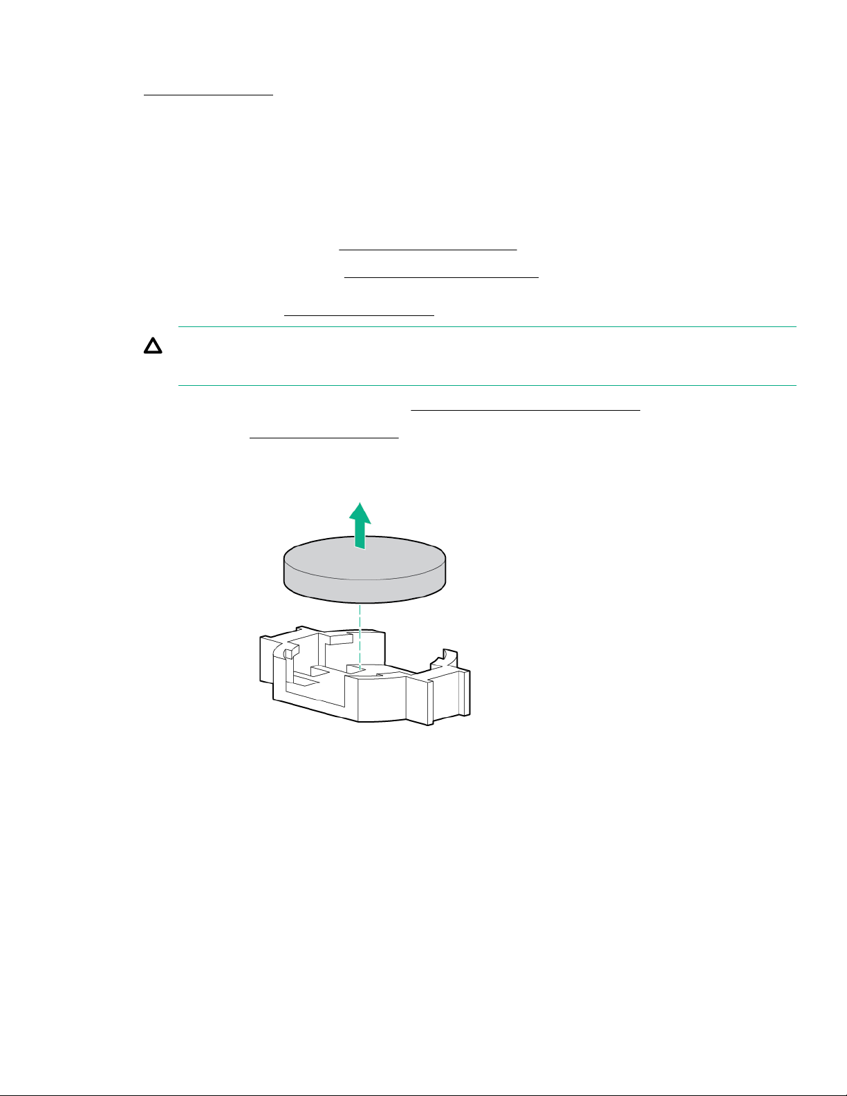
Procedure
1. Power down the server.
2. Remove all power:
a. Disconnect each power cord from the power source.
b. Disconnect each power cord from the server.
3. Do one of the following:
• Extend the server from the rack (
• Remove the server from the rack (Removing the server from the rack).
4. Remove the access panel (Removing the access panel).
CAUTION: Do not operate the server for long periods with the access panel open or removed. Operating the server
in this manner results in improper airflow and improper cooling that can lead to thermal damage.
If installed, remove the secondary PCIe riser cage (Removing and replacing a PCIe riser cage).
5.
Locate the battery (System board components).
6.
Remove the battery.
7.
Extend the server from the rack).
8. To replace the component, reverse the removal procedure.
9. Properly dispose of the old battery.
For more information about battery replacement or proper disposal, contact an authorized reseller or an authorized service
provider.
Removing and replacing the system board
Prerequisites
If HPE Persistent Memory modules are installed in the server and are encrypted with local key management, do one of the
following:
Removal and replacement procedures
93
Page 94

• Manually retrieve the HPE Persistent Memory module passwords from the server (user-generated passwords only)
• Export a password file to a USB key.
Hewlett Packard Enterprise recommends exporting the password file to a USB key.
For more information, see the HPE Persistent Memory User Guide on the Hewlett Packard Enterprise website (https://
www.hpe.com/info/persistentmemory-docs).
Procedure
1. Power down the server (
2. Remove all power.
a. Disconnect each power cord from the power source.
b. Disconnect each power cord from the server.
3. Do one of the following:
• Extend the server from the rack (
• Remove the server from the rack (Removing the server from the rack).
Remove the access panel (
4.
If installed, do the following:
5.
Remove the air bale (Removing and replacing the air bale).
a.
Remove the processor mezzanine tray (Removing and replacing the processor mezzanine tray).
b.
Remove the CPU Mezzanine UPI performance kit (
c.
kit).
Remove the fan cage (
6.
Power down the server).
Extend the server from the rack).
Removing the access panel).
Removing and replacing the CPU Mezzanine UPI performance
Removing and replacing the fan cage).
Remove the smart storage batteries (Removing and replacing an energy pack).
7.
Remove the PCIe riser cages (Removing and replacing a PCIe riser cage).
8.
Remove the FlexLOM (
9.
Disconnect all cables connected to the system board.
10.
11. Remove the system board:
a. Remove the screws from the side of the server.
b. Loosen the thumbscrew.
c. Slide the system board toward the front of the server, and then lift it from the server.
94
Removal and replacement procedures
Removing and replacing the FlexibleLOM).
Page 95
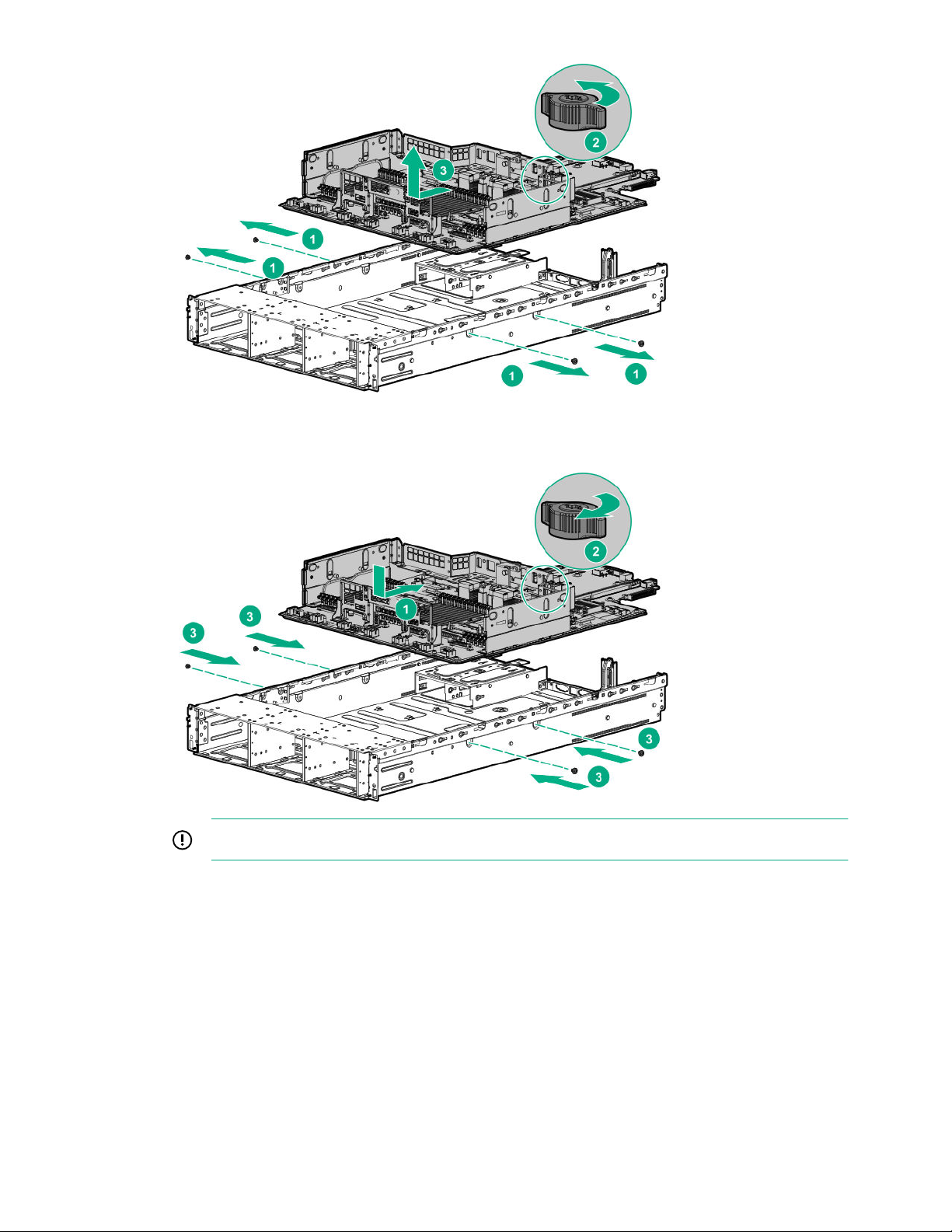
Replacing the system board
12. Install the spare system board.
13.
14.
15. Install the fan cage.
16. If removed, do the following:
IMPORTANT: Install all components with the same configuration that was used on the failed system board.
Install all components removed from the failed system board.
Be sure to install the DIMMs and HPE Persistent Memory modules in the same DIMM slots as the failed system board.
Removal and replacement procedures
95
Page 96
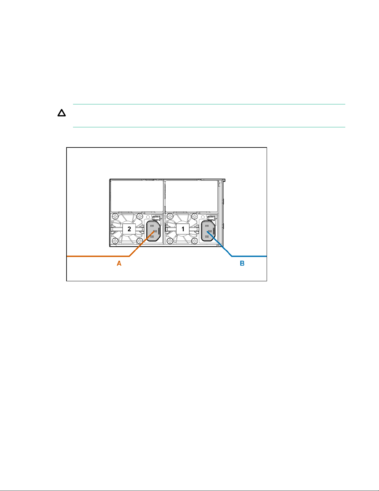
a. Install the air bale.
b. Install the processor mezzanine tray.
c. Install the CPU Mezzanine UPI performance kit.
17. Install the access panel.
18. Install the server into the rack.
19. Connect the power cord to the power supply.
CAUTION: Connect the power cords using only the following supported configurations. Using an unsupported
power supply or cabling configuration can result in an unexpected loss of system power.
• Two power supply configuration—For redundancy, connect power supplies 1 and 2 to separate AC power circuits.
• Four power supply configuration—For redundancy, connect power supplies 1 and 2 to power circuit A, and then
connect power supplies 3 and 4 to power circuit B.
96
Removal and replacement procedures
Page 97
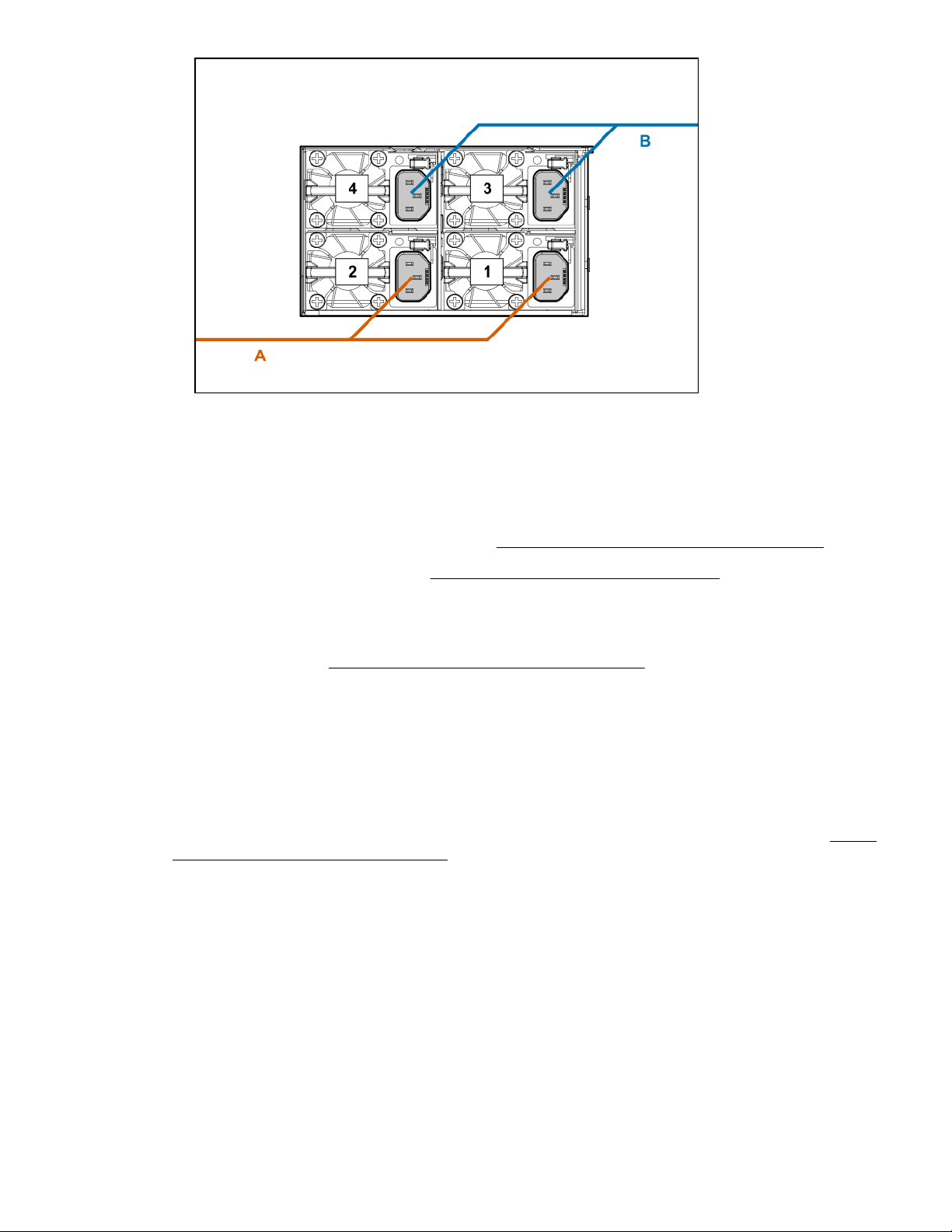
20. Power up the server.
Ensure all firmware, including option cards and embedded devices, is updated to the same versions to ensure that the
21.
latest drivers are being used.
Re-enter any Secure Boot Keys that were previously added in the Secure Boot configuration.
22.
Re-enter the server serial number and the product ID (
23.
Set the server power supply requirements (
24.
25.
Review the persistent memory configuration of the server.
26.
For more information, see Configuring the server for HPE Persistent Memory.
Do one of the following:
27.
• If HPE Persistent Memory modules are encrypted with local key management, either manually enter the HPE
Persistent Memory module passwords in the System Utilities or import the password file from the USB key.
• If HPE Persistent Memory modules are encrypted with remote key management, enroll the server iLO in the key
management server to provide access to the data on the HPE Persistent Memory modules.
For more information, see the HPE Persistent Memory User Guide on the Hewlett Packard Enterprise website (https://
www.hpe.com/info/persistentmemory-docs).
Setting the server power supply requirements).
Re-entering the server serial number and product ID).
Re-entering the server serial number and product ID
After you replace the system board, the server serial number and the product ID must be configured:
Procedure
1. Access System Utilities. During POST, press F9.
2. On the System Utilities home screen, select System Configuration > BIOS/Platform Configuration (RBSU) > Advanced
Options > Advanced Service Options.
3. Select the Serial Number field and press Enter.
Removal and replacement procedures
97
Page 98

The following alert appears:
The serial number is modified by qualified service personnel and must match
the serial number located on the chassis.
4. Click OK.
5. Type the serial number and press Enter.
6. Select the Product ID field and press Enter.
The following alert appears:
Product ID is modified only by qualified personnel. This value must match the
product ID located on the chassis.
7. Type the product ID and press Enter.
8. Press F10 to save the configuration.
The procedure is complete.
Setting the server power supply requirements
The server supports four power supply redundancy modes in UEFI System Utilities. To determine if your current server
hardware configuration can support a specific redundancy setting, use the HPE Power Advisor on the Hewlett Packard
Enterprise website (
http://www.hpe.com/info/poweradvisor/online).
• 1 + 1 Redundancy—In a two-power supply configuration, the server will continue to operate if one power supply fails. This
mode is not applicable in a four-power supply configuration.
• 2 + 2 Redundancy—In a four-power supply configuration, the server will continue to operate if two power supplies fail or if
one AC feed loses power.
• 3 + 1 Redundancy—In a four-power supply configuration, the server will continue to operate if a single power supply fails.
The server will initiate operating system shutdown if two power supplies fail. No AC power redundancy is possible.
• 4 + 0 Redundancy—In a four-power supply configuration, there is no power supply redundancy. The server consumes
more power than what redundancy can supply, and will initiate operating system shutdown if one or more power supplies
fail.
By default, the server is configured for 1 + 1 power redundancy.
To verify that the server is cabled properly for AC power redundancy, see
Procedure
1. Use the HPE Power Advisor (
system and verify that the server will continue to operate redundantly in the default configuration.
To change the redundancy setting in the UEFI System Utilities, proceed with the following steps.
2. To access the UEFI System Utilities, press F9 during POST.
3. From the System Utilities screen, select System Configuration > BIOS/Platform Configuration (RBSU) > Advanced
Options.
http://www.hpe.com/info/poweradvisor/online) to determine the power draw of the
Removing and replacing the system board.
4. Select the appropriate redundancy configuration from the Power Supply Requirements menu, and then press Enter.
5. Press F10 to Save or F12 to Save and Exit.
98
Removal and replacement procedures
Page 99

HPE Trusted Platform Module 2.0 Gen10 Option
The HPE Trusted Platform Module 20 Gen10 Option is not a customer-removable part.
CAUTION: If the TPM is removed from the original server and powered up on a dierent server, data stored in the TPM
including keys will be erased.
If you suspect a TPM board failure, leave the TPM installed and remove the system board. Contact a Hewlett Packard
Enterprise authorized service provider for a replacement system board and TPM board.
Removal and replacement procedures 99
Page 100

Troubleshooting
Troubleshooting resources
Troubleshooting resources are available for HPE Gen10 server products in the following documents:
• Troubleshooting Guide for HPE ProLiant Gen10 servers provides procedures for resolving common problems and
comprehensive courses of action for fault isolation and identification, issue resolution, and software maintenance.
• Error Message Guide for HPE ProLiant Gen10 servers and HPE Synergy provides a list of error messages and information
to assist with interpreting and resolving error messages.
• Integrated Management Log Messages and Troubleshooting Guide for HPE ProLiant Gen10 and HPE Synergy provides
IML messages and associated troubleshooting information to resolve critical and cautionary IML events.
To access the troubleshooting resources, see the Hewlett Packard Enterprise Information Library (
info/gen10-troubleshooting).
https://www.hpe.com/
100 Troubleshooting
 Loading...