

HP ProLiant DL388 G7 User Manual

HP ProLiant DL388 G7 Server
Part Number: 615655-002
User Guide
Abstract
This document is for the person who installs, administers, and troubleshoots servers and storage systems. HP assumes you are qualified in the
servicing of computer equipment and trained in recognizing hazards in products with hazardous energy levels.
February 2011
Edition: 2

© Copyright 2010, 2011 Hewlett-Packard Development Company, L.P.
The information contained herein is subject to change without notice. The only warranties for HP products and services are set forth in the express
warranty statements accompanying such products and services. Nothing herein should be construed as constituting an additional warranty. HP shall
not be liable for technical or editorial errors or omissions contained herein.
Microsoft, Windows, and Windows Server are U.S. registered trademarks of Microsoft Corporation.

Contents
Component identification ............................................................................................................... 7
Front panel components ............................................................................................................................. 7
Front panel LEDs and buttons ...................................................................................................................... 8
Systems Insight Display LEDs ....................................................................................................................... 9
Systems Insight Display LED combinations ................................................................................................... 10
Rear panel components ............................................................................................................................ 11
Rear panel LEDs and buttons ..................................................................................................................... 12
Non-hot-plug PCI riser board slot definitions ................................................................................................ 12
System board components ........................................................................................................................ 14
System maintenance switch ............................................................................................................. 15
NMI functionality ........................................................................................................................... 15
DIMM slot locations ....................................................................................................................... 16
SAS and SATA device numbers ................................................................................................................. 17
SAS and SATA hard drive LEDs ................................................................................................................. 18
SAS and SATA hard drive LED combinations .............................................................................................. 18
PCI riser cage LEDs .................................................................................................................................. 19
FBWC module LEDs ................................................................................................................................. 20
Battery pack LEDs .................................................................................................................................... 21
Hot-plug fans .......................................................................................................................................... 22
Operations ................................................................................................................................. 24
Power up the server ................................................................................................................................. 24
Power down the server ............................................................................................................................. 24
Extend the server from the rack ................................................................................................................. 24
Remove the access panel.......................................................................................................................... 25
Install the access panel............................................................................................................................. 26
Access the product rear panel ................................................................................................................... 26
Cable management arm with left-hand swing .................................................................................... 26
Cable management arm with right-hand swing .................................................................................. 27
Remove the full-length expansion board retainer .......................................................................................... 28
Remove the PCI riser cage ........................................................................................................................ 29
Install the PCI riser cage ........................................................................................................................... 29
Install the full-length expansion board retainer ............................................................................................. 30
Remove the air baffle ............................................................................................................................... 31
Setup ......................................................................................................................................... 32
Optional installation services .................................................................................................................... 32
Rack planning resources........................................................................................................................... 32
Optimum environment .............................................................................................................................. 33
Space and airflow requirements ...................................................................................................... 33
Temperature requirements ............................................................................................................... 34
Power requirements ....................................................................................................................... 34
Electrical grounding requirements .................................................................................................... 34
Rack warnings ........................................................................................................................................ 35
Identifying the contents of the server shipping carton .................................................................................... 35
Installing hardware options ....................................................................................................................... 35
Installing the server into the rack ................................................................................................................ 35
Contents 3

Installing the operating system................................................................................................................... 37
Powering up and configuring the server ..................................................................................................... 37
Registering the server ............................................................................................................................... 38
Hardware options installation ....................................................................................................... 39
Introduction ............................................................................................................................................ 39
Processor option ...................................................................................................................................... 39
Memory options ...................................................................................................................................... 46
Memory subsystem architecture ....................................................................................................... 46
Single-, dual-, and quad-rank DIMMs ............................................................................................... 46
DIMM identification ....................................................................................................................... 47
Memory configurations ................................................................................................................... 47
General DIMM slot population guidelines ......................................................................................... 49
Installing a DIMM .......................................................................................................................... 53
Hot-plug SAS hard drive options ............................................................................................................... 54
Installing a hot-plug SAS hard drive ................................................................................................. 54
Removing a hot-plug SAS hard drive ................................................................................................ 55
Flash-backed write cache module option .................................................................................................... 55
Optical drive option ................................................................................................................................ 57
Redundant hot-plug power supply option .................................................................................................... 59
Expansion board options .......................................................................................................................... 60
Removing expansion slot covers ...................................................................................................... 60
Installing a half-length expansion board ........................................................................................... 62
Installing a full-length expansion board ............................................................................................. 62
PCI riser board option .............................................................................................................................. 63
Hard drive cage option ............................................................................................................................ 64
HP Trusted Platform Module option ............................................................................................................ 65
Installing the Trusted Platform Module board ..................................................................................... 66
Retaining the recovery key/password .............................................................................................. 68
Enabling the Trusted Platform Module ............................................................................................... 68
Cabling ..................................................................................................................................... 69
SAS hard drive cabling ............................................................................................................................ 69
Optical drive cabling ............................................................................................................................... 69
BBWC battery cabling ............................................................................................................................. 70
FBWC battery cabling ............................................................................................................................. 70
Configuration and utilities ............................................................................................................ 71
Configuration tools .................................................................................................................................. 71
SmartStart software ........................................................................................................................ 71
HP ROM-Based Setup Utility ............................................................................................................ 72
Array Configuration Utility .............................................................................................................. 75
Option ROM Configuration for Arrays ............................................................................................. 75
Re-entering the server serial number and product ID ........................................................................... 76
Management tools ................................................................................................................................... 76
Automatic Server Recovery ............................................................................................................. 76
ROMPaq utility .............................................................................................................................. 77
Integrated Lights-Out 3 technology ................................................................................................... 77
Erase Utility .................................................................................................................................. 77
Redundant ROM support ................................................................................................................ 78
USB support and functionality ......................................................................................................... 78
Internal SD support ........................................................................................................................ 79
Diagnostic tools ...................................................................................................................................... 79
HP Insight Diagnostics .................................................................................................................... 79
Contents 4

HP Insight Diagnostics survey functionality ........................................................................................ 79
Integrated Management Log ........................................................................................................... 79
Remote support and analysis tools ............................................................................................................. 80
HP Insight Remote Support software ................................................................................................. 80
Keeping the system current ....................................................................................................................... 80
Drivers ......................................................................................................................................... 80
Version control .............................................................................................................................. 81
ProLiant Support Packs ................................................................................................................... 81
Operating System Version Support .................................................................................................. 81
Firmware ...................................................................................................................................... 82
HP Smart Update Manager ............................................................................................................. 82
Change control and proactive notification ........................................................................................ 82
Care Pack .................................................................................................................................... 83
Troubleshooting .......................................................................................................................... 84
Troubleshooting resources ........................................................................................................................ 84
Pre-diagnostic steps ................................................................................................................................. 84
Important safety information ............................................................................................................ 84
Symptom information ..................................................................................................................... 86
Prepare the server for diagnosis ...................................................................................................... 86
Loose connections ................................................................................................................................... 88
Service notifications ................................................................................................................................. 88
Server health LEDs ................................................................................................................................... 88
Troubleshooting flowcharts ....................................................................................................................... 88
Start diagnosis flowchart ................................................................................................................ 89
General diagnosis flowchart ........................................................................................................... 90
Server blade power-on problems flowchart ....................................................................................... 92
POST problems flowchart ............................................................................................................... 94
OS boot problems flowchart ........................................................................................................... 96
Server fault indications flowchart ..................................................................................................... 98
POST error messages and beep codes ..................................................................................................... 100
Battery replacement .................................................................................................................. 102
Regulatory compliance notices ................................................................................................... 103
Regulatory compliance identification numbers ........................................................................................... 103
Federal Communications Commission notice ............................................................................................. 103
FCC rating label .......................................................................................................................... 103
Class A equipment....................................................................................................................... 103
Class B equipment ....................................................................................................................... 103
Declaration of conformity for products marked with the FCC logo, United States only ..................................... 104
Modifications ........................................................................................................................................ 104
Cables ................................................................................................................................................. 104
Canadian notice (Avis Canadien) ............................................................................................................ 104
European Union regulatory notice ........................................................................................................... 105
Disposal of waste equipment by users in private households in the European Union ....................................... 105
Japanese notice .................................................................................................................................... 106
BSMI notice .......................................................................................................................................... 106
Korean notice ....................................................................................................................................... 106
Chinese notice ...................................................................................................................................... 107
Laser compliance .................................................................................................................................. 107
Battery replacement notice ...................................................................................................................... 107
Taiwan battery recycling notice ............................................................................................................... 108
Power cord statement for Japan ............................................................................................................... 108
Contents 5

Electrostatic discharge ............................................................................................................... 109
Preventing electrostatic discharge ............................................................................................................ 109
Grounding methods to prevent electrostatic discharge ................................................................................ 109
Specifications ........................................................................................................................... 110
Environmental specifications ................................................................................................................... 110
Mechanical specifications ...................................................................................................................... 110
Power supply specifications .................................................................................................................... 110
Technical support ...................................................................................................................... 113
Before you contact HP ............................................................................................................................ 113
HP contact information ........................................................................................................................... 113
Customer Self Repair ............................................................................................................................. 113
Acronyms and abbreviations ...................................................................................................... 121
Index ....................................................................................................................................... 124
Contents 6
Component identification
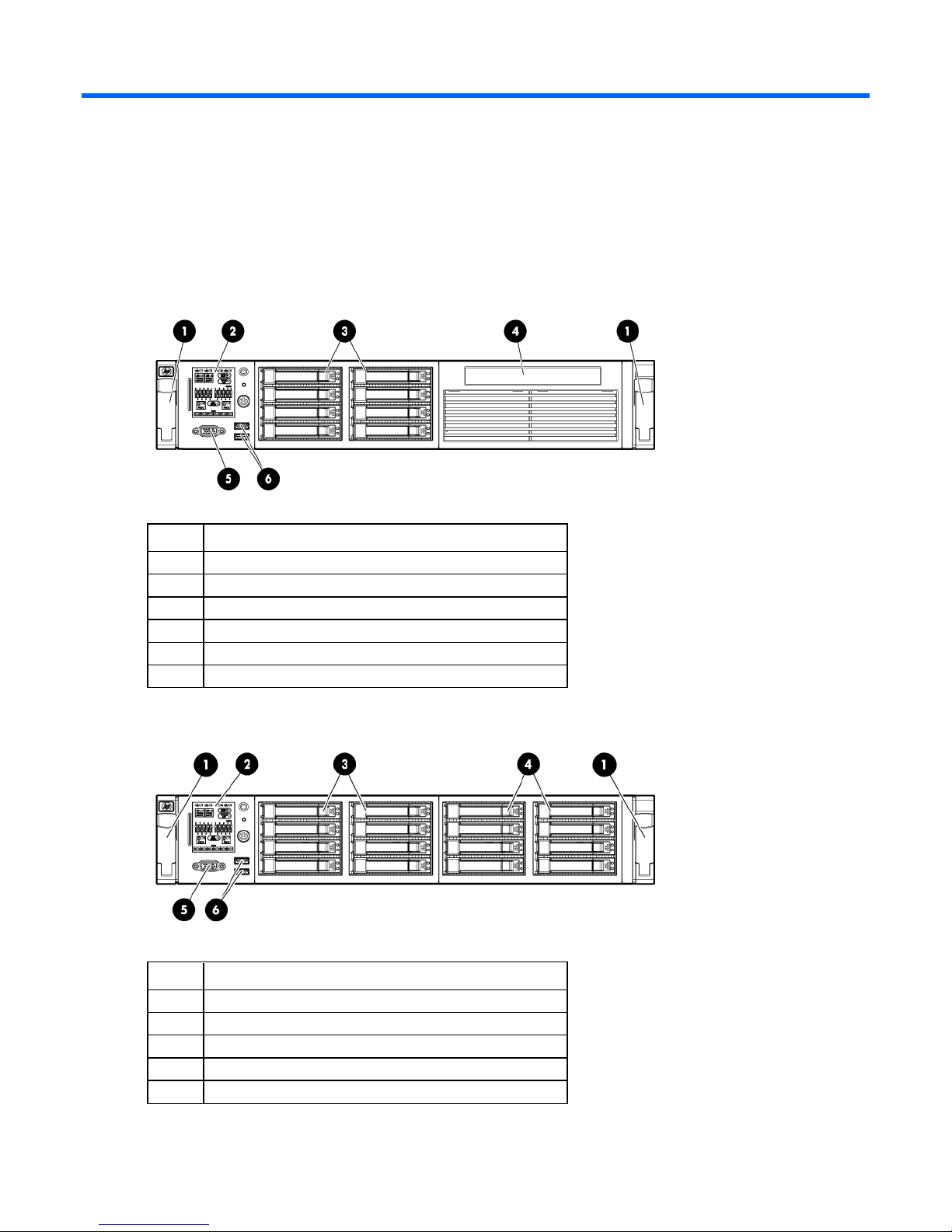
Front panel components
• SFF model
Item Description
1
2
3
4
5
6
Quick release levers (2)
Systems Insight Display
Hard drive bays
SATA optical drive bay
Video connector
USB connectors (2)
• SFF model with optional hard drive cage
Item Description
1
2
3
4
5
Quick release levers (2)
Systems Insight Display
Hard drive bays
Hard drive bays (optional)
Video connector
Component identification 7
Item Description
6
USB connectors (2)
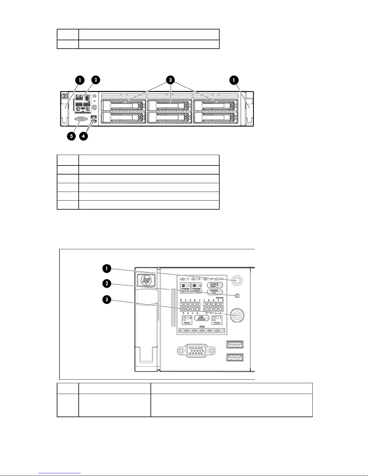
• LFF model
Item Description
1
2
3
4
5
Quick release levers (2)
Systems Insight Display
Hard drive bays
USB connectors (2)
Video connector
Front panel LEDs and buttons
Item Description Status
1
UID LED and button Blue = Activated
Flashing blue = System being remotely managed
Off = Deactivated
Component identification 8
Item Description Status
2
3
System health LED Green = Normal
Amber = System degraded.
Red = System critical.
To identify components in degraded or critical state, see "Systems
Insight Display LEDs (on page 9)."
Power On/Standby button
and system power LED
Green = System on
Amber = System in standby, but power is still applied
Off = Power cord not attached or power supply failure
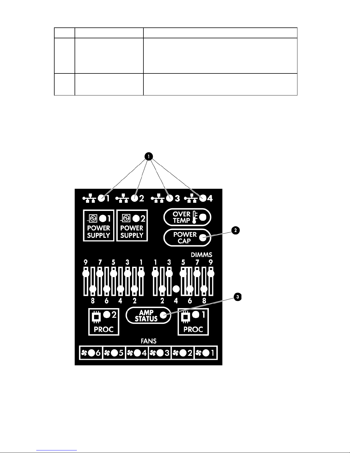
Systems Insight Display LEDs
The HP Systems Insight Display LEDs represent the system board layout. The display enables diagnosis with
the access panel installed.
Component identification 9

•
•
•
•
Amber
Green
Processor in socket X is in a pre-failure
Item Description Status
1
2
3
NIC link/activity LED Green = Network link
Flashing green = Network link and activity
Off = No link to network. If the power is off,
view the rear panel RJ-45 LEDs for status
("Rear panel LEDs and buttons" on page
12)
Power cap To determine Power cap status, see
"Systems Insight Display LED combinations
(on page 10)."
AMP status Green = AMP mode enabled
Amber = Failover
Flashing amber = invalid configuration
Off = AMP modes disabled
—
All other LEDs Off = Normal
Amber = Failure
For detailed information on the activation
of these LEDs, see "Systems Insight Display
LED combinations (on page 10)."
Systems Insight Display LED combinations
When the health LED on the front panel illuminates either amber or red, the server is experiencing a health
event. Combinations of illuminated Systems Insight Display LEDs, the system power LED, and the health LED
indicate system status.
Systems Insight Display
LED and color
Processor (amber)
Processor (amber)
DIMM (amber)
DIMM (amber)
Overtemperature (amber)
Overtemperature (amber)
Fan (amber)
Fan (amber)
Health LED System power
Status
LED
Red Amber One or more of the following conditions may
exist:
Processor in socket X has failed.
Processor X is not installed in the socket.
Processor X is unsupported.
ROM detects a failed processor during
POST
condition.
Red Green One or more DIMMs have failed.
Amber Green DIMM in slot X is in a pre-failure condition.
Amber Green The Health Driver has detected a cautionary
temperature level.
Red Amber The server has detected a hardware critical
temperature level.
Amber Green One fan has failed or has been removed.
Red Green Two or more fans have failed or been
removed.
Component identification 10

Red
Amber
•
•
•
•
•
•
•
Systems Insight Display
LED and color
Power supply (amber)
Health LED System power
LED
Status
Only one power supply is installed and
that power supply is in standby.
Power supply fault
System board fault
Power supply (amber)
Amber Green
Redundant power supply is installed and
only one power supply is functional.
AC power cord is not plugged into
redundant power supply.
Redundant power supply fault
Power supply mismatch at POST or
power supply mismatch through hot-plug
addition.
Power cap (off)
Power cap (green)
Power cap (flashing
amber)
Power cap (green)
IMPORTANT: If more than one DIMM slot LED is illuminated, further troubleshooting is required.
— Amber Standby
— Flashing green Waiting for power
— Amber Power cap has been exceeded
— Green Power is available
Test each bank of DIMMs by removing all other DIMMs. Isolate the failed DIMM by replacing
each DIMM in a bank with a known working DIMM.
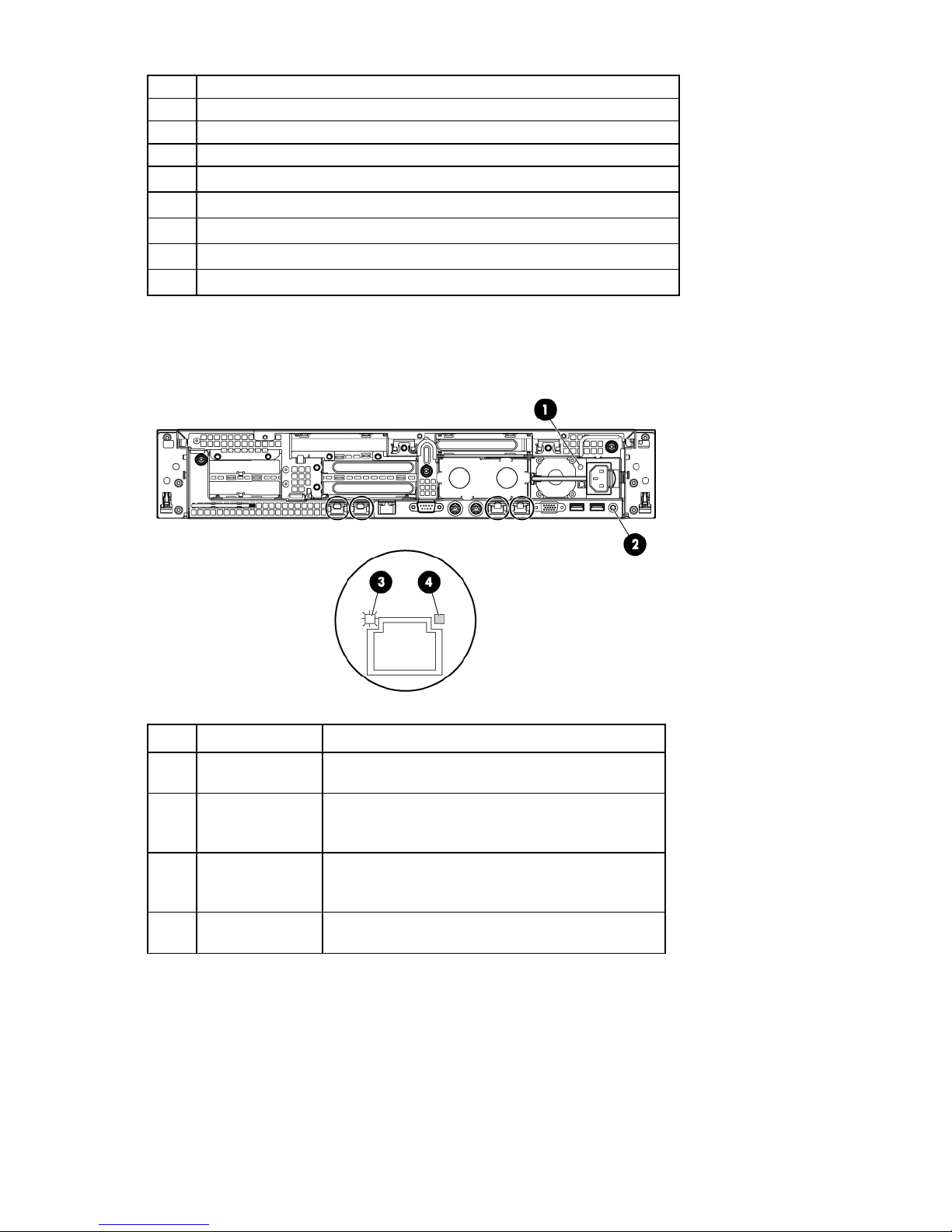
Rear panel components
Item Description
1
2
3
4
5
6
7
8
9
PCI slot 5
PCI slot 6
PCI slot 4
PCI slot 2
PCI slot 3
PCI slot 1
Power supply bay 2
Power supply bay 1 (populated)
USB connectors (2)
Component identification 11
10
Video connector
11
12
13
14
15
16
17
18
NIC 1 connector
NIC 2 connector
Mouse connector
Keyboard connector
Serial connector
iLO 3 connector
NIC 3 connector
NIC 4 connector
Rear panel LEDs and buttons
Item Description Status
1
2
3
4
Power supply LED Green = Normal
Off = System is off or power supply has failed.
UID LED/button Blue = Activated
Flashing blue = System being managed remotely
Off = Deactivated
NIC/iLO 3 activity
LED
Green = Network activity
Flashing green = Network activity
Off = No network activity
NIC/iLO 3 link LED Green = Network link
Off = No network link
Non-hot-plug PCI riser board slot definitions
Component identification 12
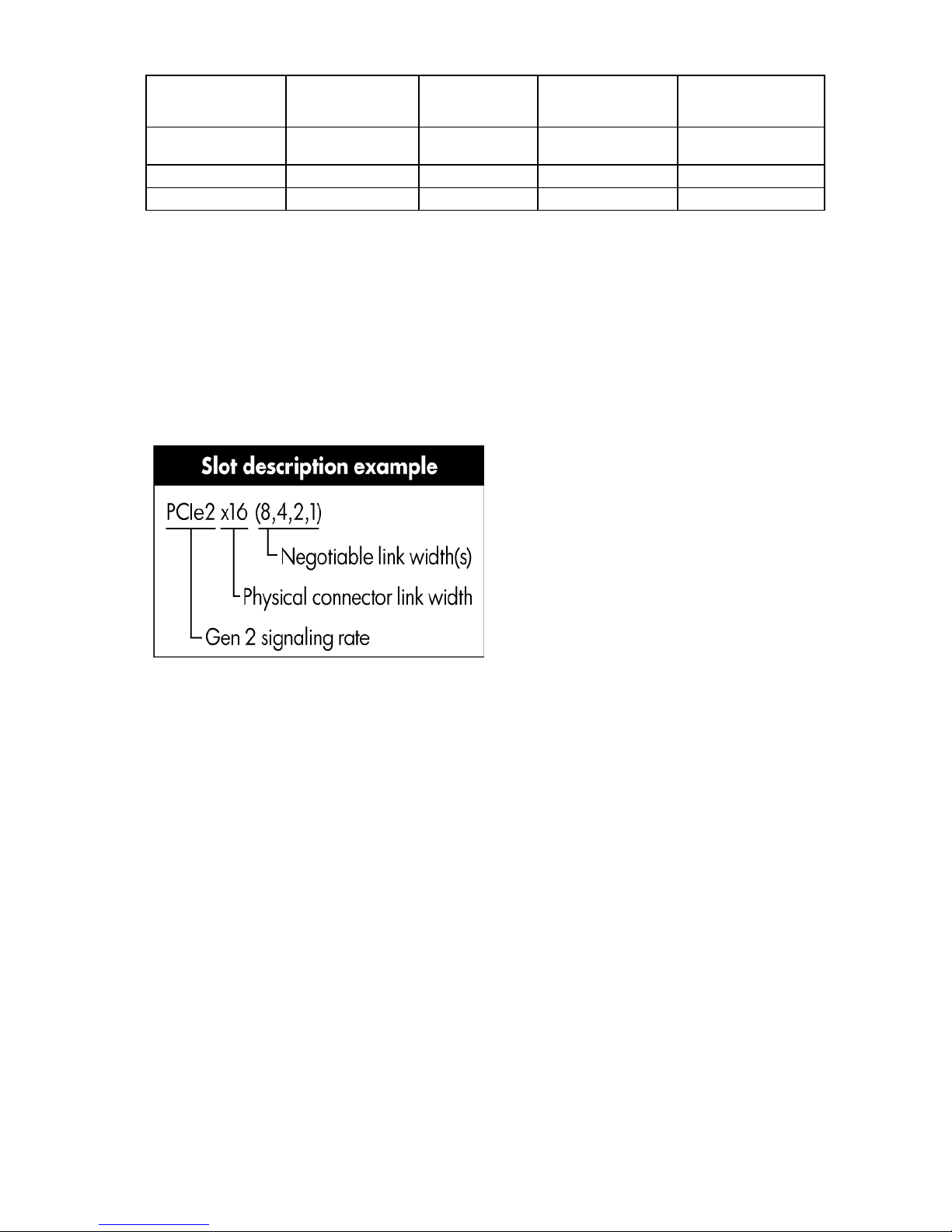
1 - FL/FH
PCIe2 x16 (8,4,1)
PCIe2 x16
PCI-X 64 bit/133 MHz
Secondary
(slot - form factor)
4 - FL/FH
5 - LP
6 - LP
Primary
(slot - form factor)
2 - HL/FH PCIe2 x8 (4,1) — PCIe2 x16 (8,4,1)
3 - HL/FH PCIe2 x8 (4,1) — PCIe2 x8 (4,1)
PCIe2 riser
slot description
PCIe2 x16 riser
slot description
(16,8,4,1)
PCIe2/PCI-X riser
slot description
Notes:
• "Primary" denotes the risers are installed in the primary riser connector.
• "Secondary" denotes the risers are installed in the secondary riser connector.
• Installing the risers listed in the table above in either the primary or secondary riser connectors
determines the form factor of the PCI cards supported by those risers.
• FL/FH denotes full-length, full-height. HL/FH denotes half-length, full-height. LP denotes low profile.
• The PCIe2 x16 riser supports a maximum power of 150 W with an HP power cable. This cable must be
used for PCIe card wattages greater than 75 W.
Component identification 13
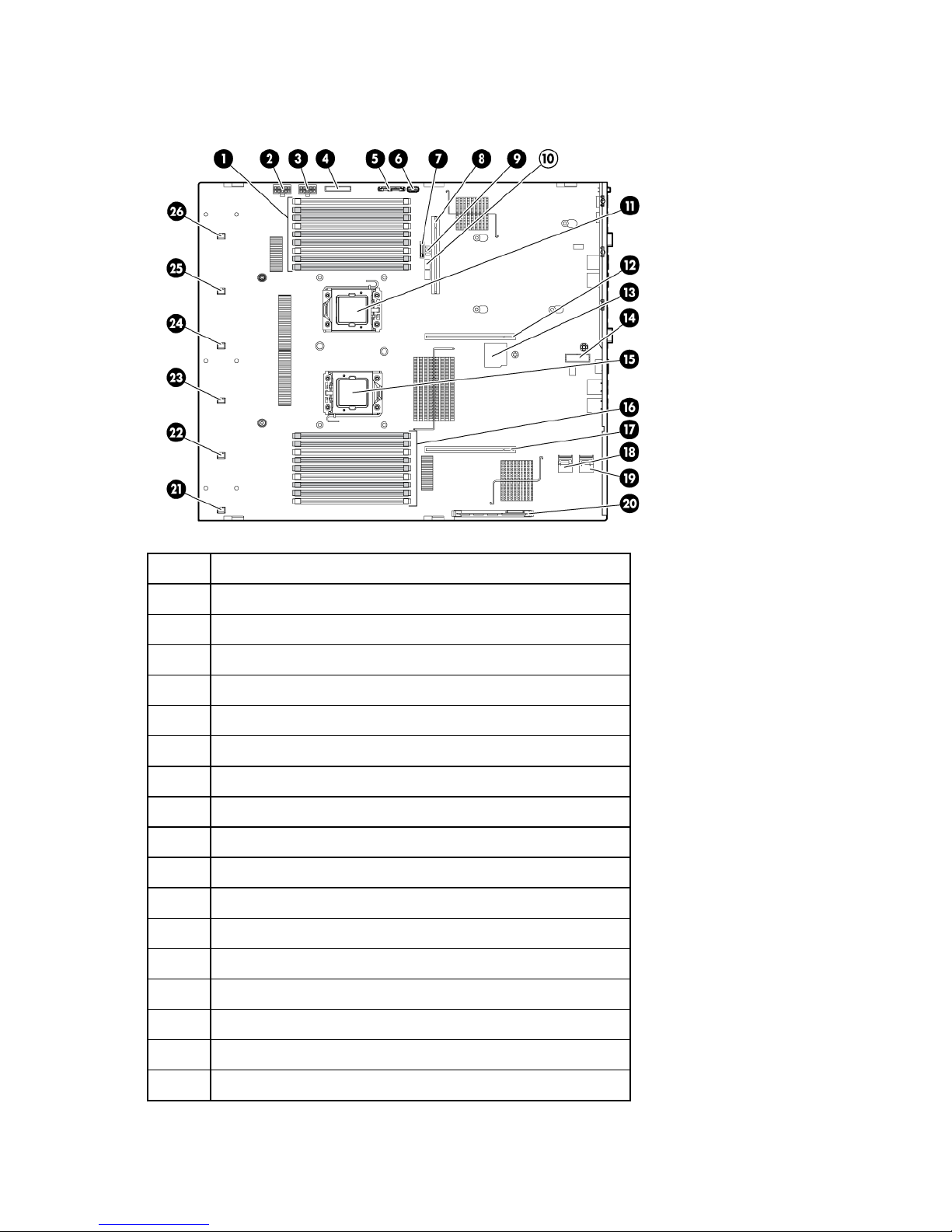
System board components
Item Description
1
2
3
4
5
6
7
8
9
10
11
12
13
14
Processor 2 DIMM slots
SAS power connector A
SAS power connector B
Front I/O connector
SATA optical drive connector
Internal USB connector
System battery
Power supply backplane connector
NMI jumper
System maintenance switch
Processor socket 2
Primary riser connector
SD card slot
TPM connector
15
16
17
Processor socket 1 (populated)
Processor 1 DIMM slots
Secondary riser connector
Component identification 14
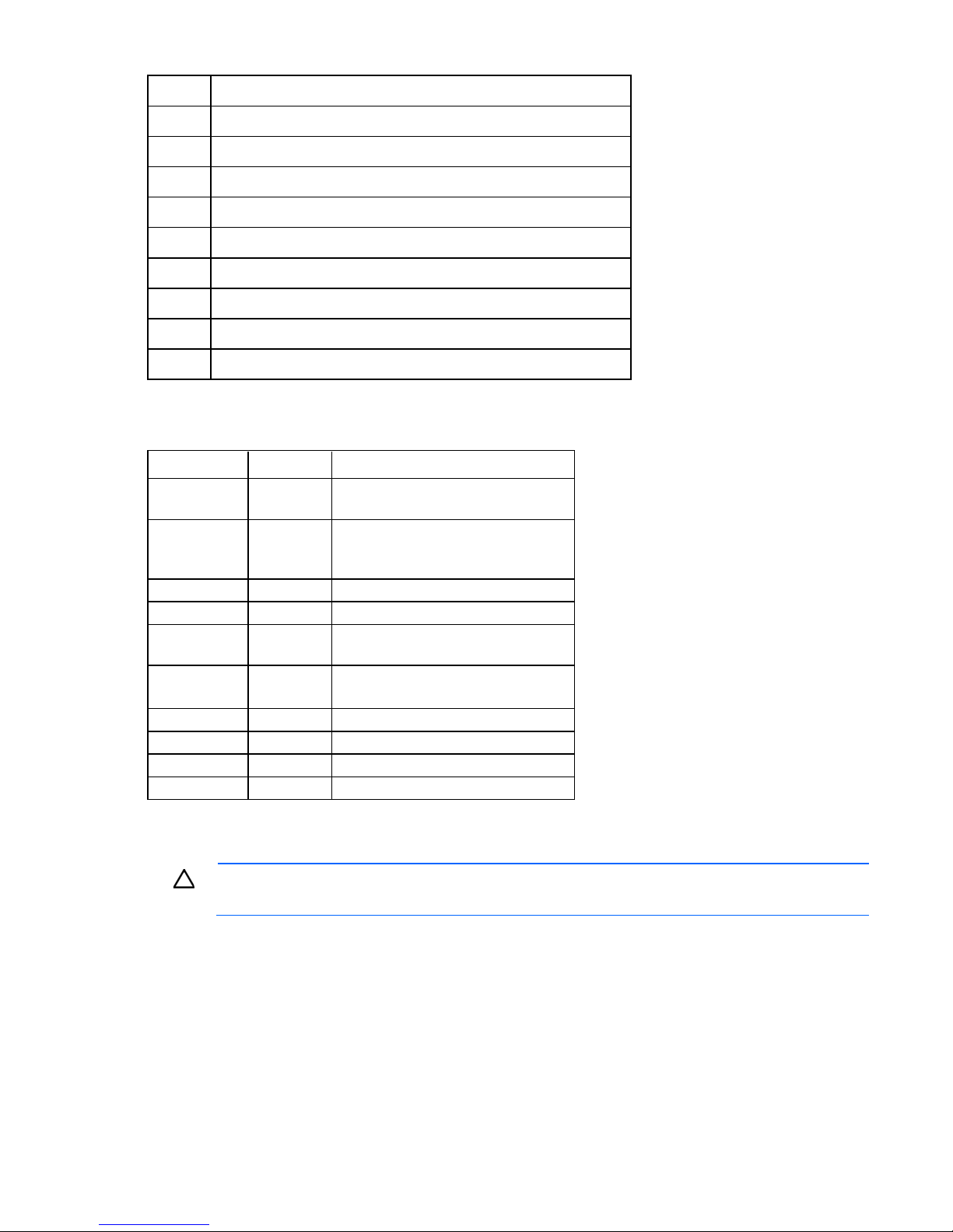
Item Description
Off
Off = Power-on password is enabled.
18
SAS connector A
19
20
21
22
23
24
25
26
SAS connector B
Cache module connector
Fan connector 1
Fan connector 2
Fan connector 3
Fan connector 4
Fan connector 5
Fan connector 6
System maintenance switch
Position Default Function
S1
S2
S3
S4
S5
S6
S7
S8
S9
S10
Off Off = iLO 3 security is enabled.
On = iLO 3 security is disabled.
Off Off = System configuration can be
changed.
On = System configuration is locked.
Off Reserved
Off Reserved
On = Power-on password is disabled.
Off Off = No function
On = Clear NVRAM
— Reserved
— Reserved
— Reserved
— Reserved
When the system maintenance switch position 6 is set to the On position, the system is prepared to erase all
system configuration settings from both CMOS and NVRAM.
CAUTION: Clearing CMOS and/or NVRAM deletes configuration information. Be sure to
properly configure the server or data loss could occur.
NMI functionality
An NMI crash dump enables administrators to create crash dump files when a system is hung and not
responding to traditional debug mechanisms.
Crash dump log analysis is an essential part of diagnosing reliability problems, such as hangs in operating
systems, device drivers, and applications. Many crashes freeze a system, and the only available action for
administrators is to cycle the system power. Resetting the system erases any information that could support
Component identification 15

problem analysis, but the NMI feature preserves that information by performing a memory dump before a
hard reset.
To force the OS to invoke the NMI handler and generate a crash dump log, the administrator can do any of
the following:
• Short the NMI jumper pins
• Press the NMI switch
• Use the iLO Virtual NMI feature
For additional information, see the whitepaper on the HP website
(http://h20000.www2.hp.com/bc/docs/support/SupportManual/c00797875/c00797875.pdf).
DIMM slot locations
DIMM slots are numbered sequentially (1 through 9) for each processor. The supported AMP modes use the
letter assignments for population guidelines.
Component identification 16
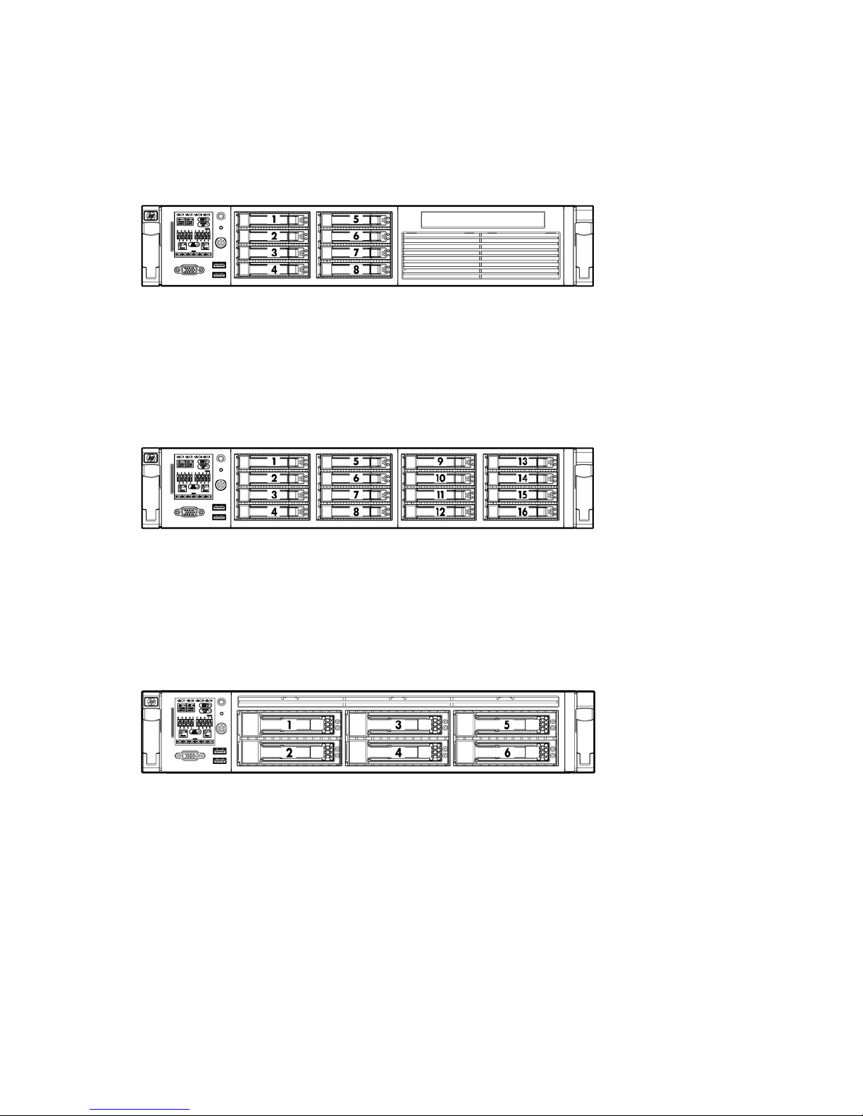
SAS and SATA device numbers
• SFF device bay numbering
• Optional SFF device bay numbering
• LFF device bay numbering
Component identification 17
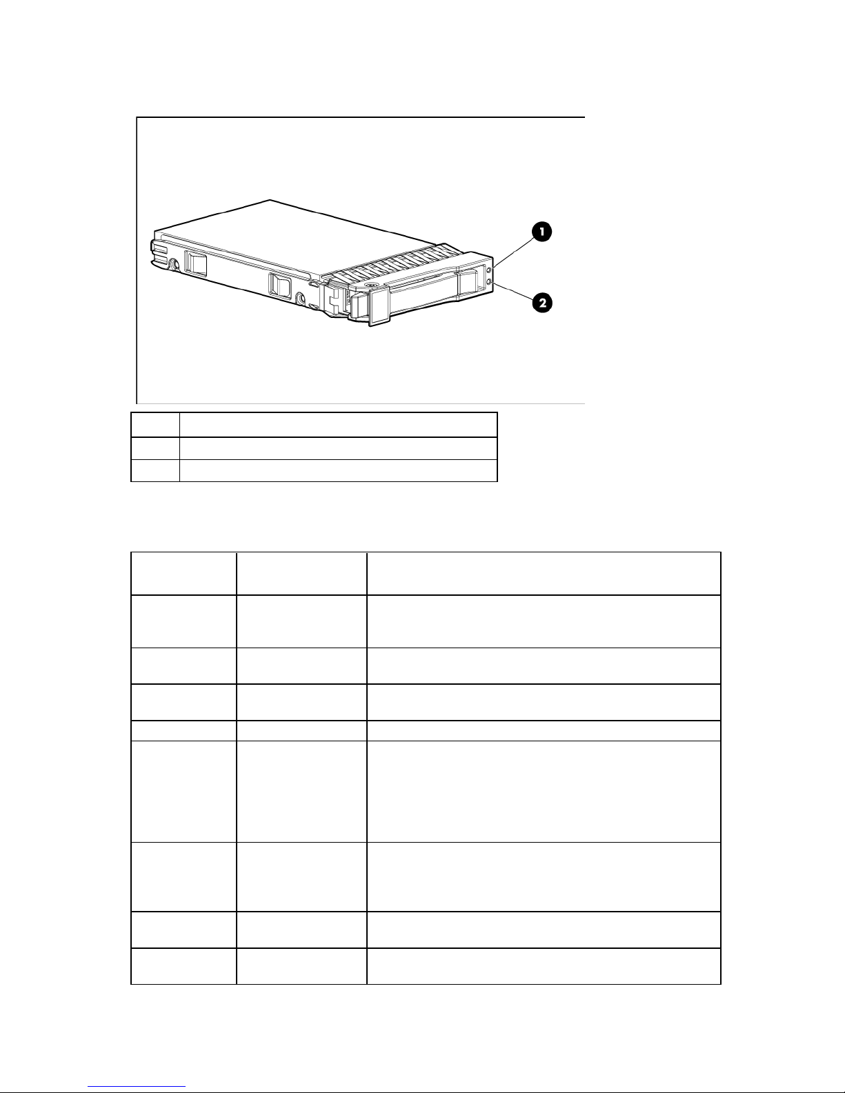
SAS and SATA hard drive LEDs
Alternating amber and
Steadily blue
The drive is operating normally, and it has been selected by a
Item Description
1
2
Fault/UID LED (amber/blue)
Online LED (green)
SAS and SATA hard drive LED combinations
Online/activity
LED (green)
On, off, or
flashing
On, off, or
flashing
On
On
Flashing regularly
(1 Hz)
Flashing regularly
(1 Hz)
Flashing
irregularly
Flashing
irregularly
Fault/UID LED
Interpretation
(amber/blue)
The drive has failed, or a predictive failure alert has been
blue
Amber, flashing
regularly (1 Hz)
Off The drive is online, but it is not active currently.
Amber, flashing
regularly (1 Hz)
Off Do not remove the drive. Removing a drive may terminate the
Amber, flashing
regularly (1 Hz)
Off The drive is active, and it is operating normally.
received for this drive; it also has been selected by a management
application.
management application.
A predictive failure alert has been received for this drive.
Replace the drive as soon as possible.
Do not remove the drive. Removing a drive may terminate the
current operation and cause data loss.
The drive is part of an array that is undergoing capacity
expansion or stripe migration, but a predictive failure alert has
been received for this drive. To minimize the risk of data loss, do
not replace the drive until the expansion or migration is complete.
current operation and cause data loss.
The drive is rebuilding, or it is part of an array that is undergoing
capacity expansion or stripe migration.
The drive is active, but a predictive failure alert has been received
for this drive. Replace the drive as soon as possible.
Component identification 18
Steadily amber
A critical fault condition has been identified for this drive, and the
Online/activity
LED (green)
Fault/UID LED
(amber/blue)
Off
Off
Amber, flashing
regularly (1 Hz)
Off
Off The drive is offline, a spare, or not configured as part of an array.
PCI riser cage LEDs
CAUTION: To prevent damage to the server or expansion boards, power down the server and
remove all AC power cords before removing or installing the PCI riser cage.
Interpretation
controller has placed it offline. Replace the drive as soon as
possible.
A predictive failure alert has been received for this drive. Replace
the drive as soon as possible.
Status
On = AC power is connected.
Off = AC power is disconnected.
Missing = Riser is not installed, or power might not be connected.
Component identification 19
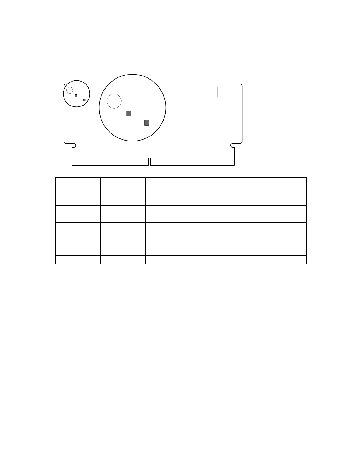
FBWC module LEDs
•
•
The FBWC module has two single-color LEDs (green and amber). The LEDs are duplicated on the reverse side
of the cache module to facilitate status viewing.
Green LED Amber LED Interpretation
Off
Flashing (1 Hz)
Flashing (1 Hz)
On
Flashing (2 Hz)
Alternating with
amber LED
On
Off
On A backup is in progress.
On A restore is in progress.
Off The capacitor pack is charging.
Off The capacitor pack has completed charging.
Flashing (2 Hz)
Alternating with
green LED
On The flash code image failed to load.
Off The flash code is corrupt.
One of the following conditions exists:
The charging process has timed out.
The capacitor pack is not connected.
Component identification 20
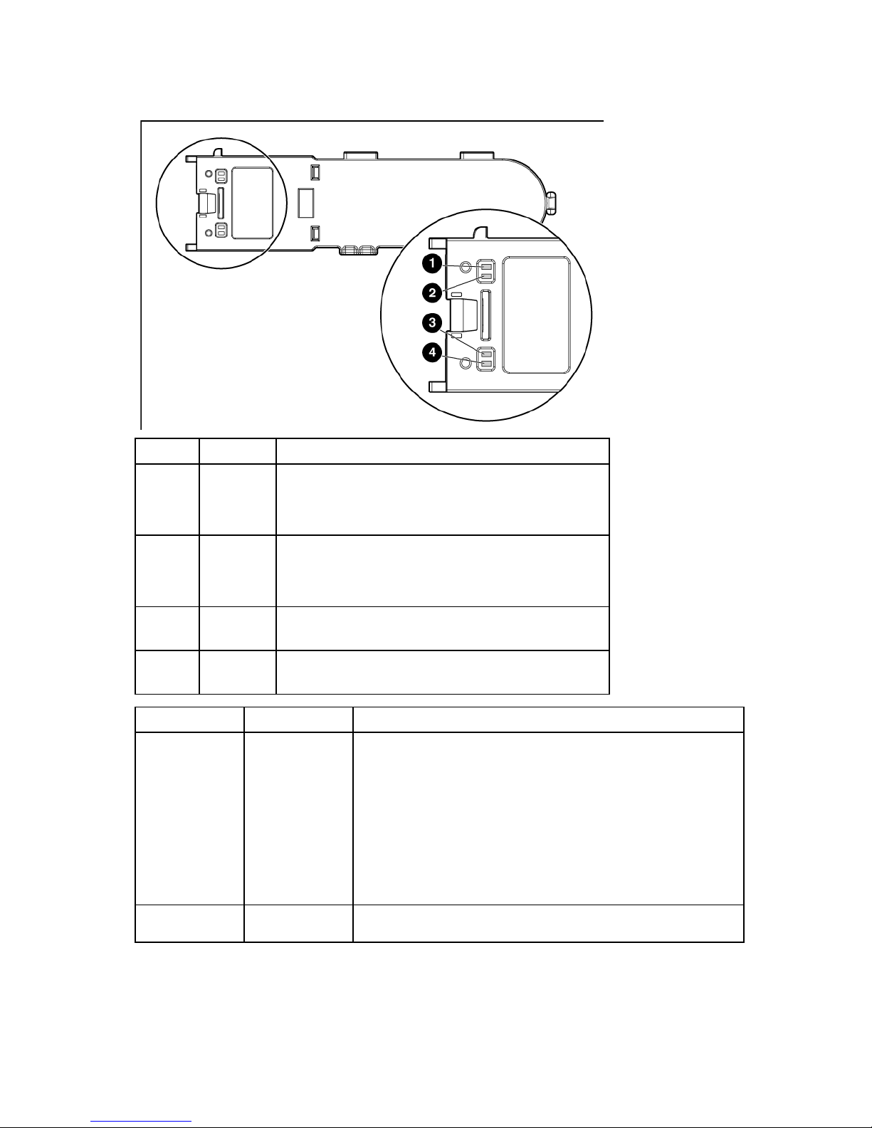
Battery pack LEDs
Item ID Color Description
1
2
3
4
Green System Power LED. This LED glows steadily when the system
is powered up and 12 V system power is available. This
power supply is used to maintain the battery charge and
provide supplementary power to the cache microcontroller.
Green Auxiliary Power LED. This LED glows steadily when 3.3V
auxiliary voltage is detected. The auxiliary voltage is used
to preserve BBWC data and is available any time that the
system power cords are connected to a power supply.
Amber Battery Health LED. To interpret the illumination patterns of
this LED, see the following table.
Green BBWC Status LED. To interpret the illumination patterns of
this LED, see the following table.
LED3 pattern LED4 pattern Interpretation
—
—
One blink every
two seconds
Double blink, then
pause
The system is powered down, and the cache contains data that has not
yet been written to the drives. Restore system power as soon as
possible to prevent data loss.
Data preservation time is extended any time that 3.3 V auxiliary
power is available, as indicated by LED 2. In the absence of auxiliary
power, battery power alone preserves the data. A fully-charged
battery can normally preserve data for at least two days.
The battery lifetime also depends on the cache module size. For further
information, refer to the controller QuickSpecs on the HP website
(http://www.hp.com).
The cache microcontroller is waiting for the host controller to
communicate.
Component identification 21
LED3 pattern LED4 pattern Interpretation
An alternating green and amber blink pattern indicates that the cache
pack. BBWC features are disabled until the battery pack is replaced.
replaced. The life expectancy of a battery pack is typically more than
—
—
—
One blink per
second
Steady glow
One blink per
second
One blink per
second
Steady glow The battery pack is fully charged, and posted write data is stored in the
Off The battery pack is fully charged, and there is no posted write data in
One blink per
second
— There is a short circuit across the battery terminals or within the battery
— There is an open circuit across the battery terminals or within the
The battery pack is below the minimum charge level and is being
charged. Features that require a battery (such as write cache, capacity
expansion, stripe size migration, and RAID migration) are temporarily
unavailable until charging is complete. The recharge process takes
between 15 minutes and two hours, depending on the initial capacity
of the battery.
cache.
the cache.
microcontroller is executing from within its boot loader and receiving
new flash code from the host controller.
The life expectancy of a battery pack is typically more than three
years.
battery pack. BBWC features are disabled until the battery pack is
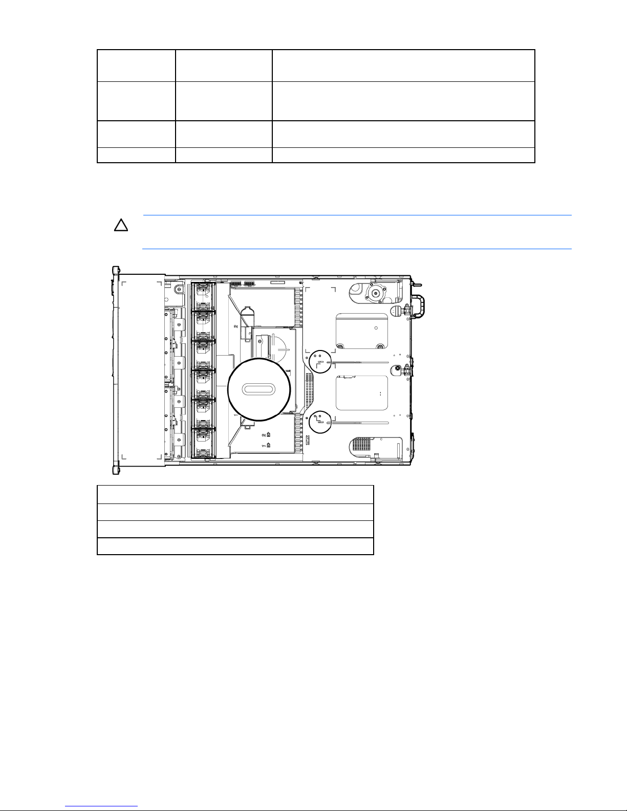
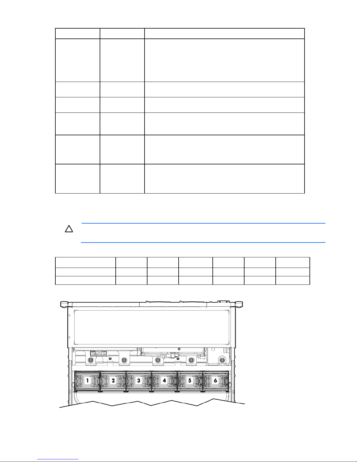
Hot-plug fans
CAUTION: To avoid damage to server components, fan blanks must be installed in fan bays 5
The only two valid fan configurations are listed in the following table.
Configuration Fan bay 1 Fan bay 2 Fan bay 3 Fan bay 4 Fan bay 5 Fan bay 6
1 processor
2 processors
and 6 in a single-processor configuration.
three years.
Fan Fan Fan Fan Fan blank Fan blank
Fan Fan Fan Fan Fan Fan
Component identification 22

For a single-processor configuration, four fans and two blanks are required in specific fan bays for
redundancy. A fan failure or missing fan causes all fans to spin at high speed. A second fan failure or missing
fan causes an orderly shutdown of the server.
Installing more than the required number of fans in a single-processor configuration is not a supported
configuration.
For a dual-processor configuration, six fans are required for redundancy. A fan failure or missing fan causes
all fans to spin at high speed. A second fan failure or missing fan causes an orderly shutdown of the server.
The server supports variable fan speeds. The fans operate at minimum speed until a temperature change
requires a fan speed increase to cool the server. The server shuts down during the following
temperature-related scenarios:
• At POST and in the OS, iLO 3 performs an orderly shutdown if a cautionary temperature level is
detected. If the server hardware detects a critical temperature level before an orderly shutdown occurs,
the server performs an immediate shutdown.
• When the Thermal Shutdown feature is disabled in RBSU, iLO 3 does not perform an orderly shutdown
when a cautionary temperature level is detected. Disabling this feature does not disable the server
hardware from performing an immediate shutdown when a critical temperature level is detected.
CAUTION: A thermal event can damage server components when the Thermal Shutdown feature
is disabled in RBSU.
Component identification 23

Operations
Power up the server
To power up the server, press the Power On/Standby button.
Power down the server
WARNING: To reduce the risk of personal injury, electric shock, or damage to the equipment,
remove the power cord to remove power from the server. The front panel Power On/Standby
button does not completely shut off system power. Portions of the power supply and some internal
1. Back up the server data.
2. Shut down the operating system as directed by the operating system documentation.
3. Press the Power On/Standby button to place the server in Standby mode. When the server activates
4. Disconnect the power cords.
circuitry remain active until AC power is removed.
IMPORTANT: If installing a hot-plug device, it is not necessary to power down the server.
NOTE: If the operating system automatically places the server in Standby mode, omit the next
step.
Standby power mode, the system power LED changes to amber.
IMPORTANT: Pressing the UID button illuminates the blue UID LEDs on the front and rear panels.
In a rack environment, this feature facilitates locating a server when moving between the front and
rear of the rack.
The system is now without power.
Extend the server from the rack
1. Pull down the quick release levers on each side of the server.
2. Extend the server from the rack.
WARNING: To reduce the risk of personal injury or equipment damage, be sure that the rack is
adequately stabilized before extending a component from the rack.
Operations 24
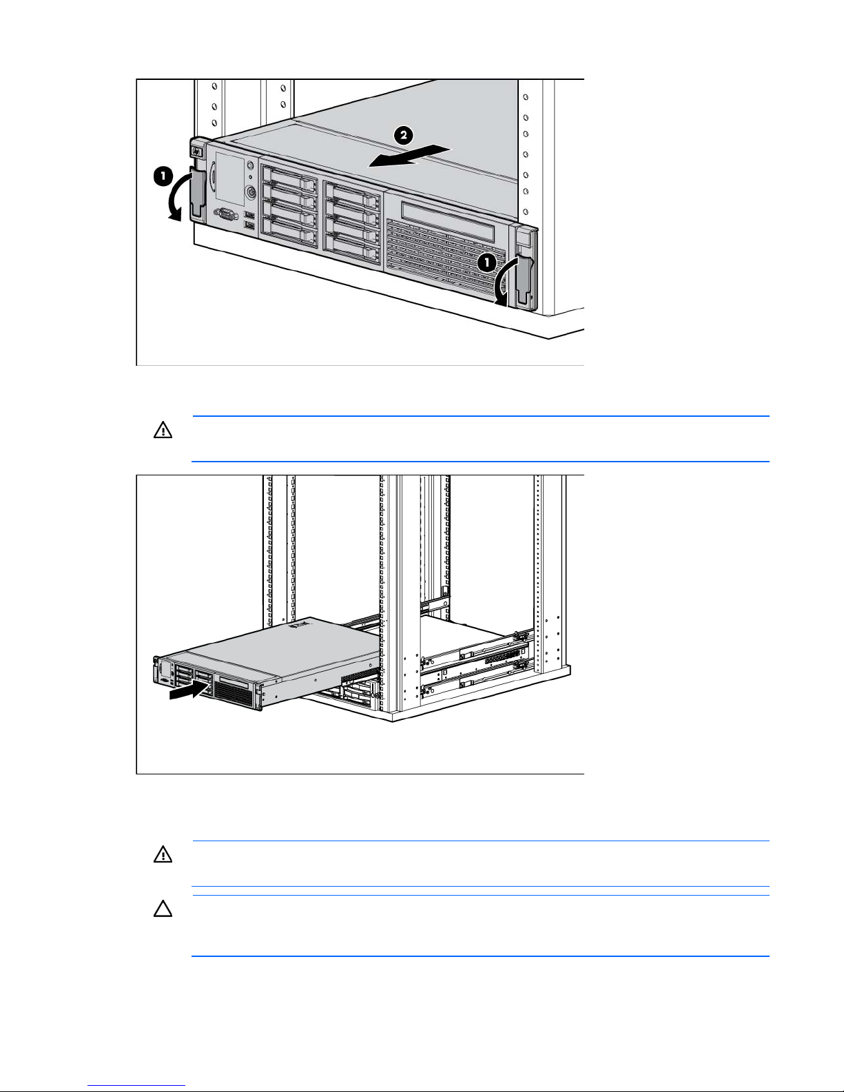
3. After performing the installation or maintenance procedure, slide the server back into the rack, and then
press the server firmly into the rack to secure it in place.
WARNING: To reduce the risk of personal injury, be careful when pressing the server rail-release
latches and sliding the server into the rack. The sliding rails could pinch your fingers.
Remove the access panel
WARNING: To reduce the risk of personal injury from hot surfaces, allow the drives and the
To remove the component:
internal system components to cool before touching them.
CAUTION: For proper cooling do not operate the server without the access panel, baffles,
expansion slot covers, or blanks installed. If the server supports hot-plug components, minimize
the amount of time the access panel is open.
Operations 25
1.
Power down the server if performing a non-hot-plug installation or maintenance procedure ("Power
down the server" on page 24).
2. Extend the server from the rack (on page 24).
3. Use the T-15 Torx screwdriver attached to the rear of the server to loosen the security screw on the hood
latch.
4. Lift up on the hood latch handle, and then remove the access panel.
Install the access panel
1. Place the access panel on top of the server with the hood latch open. Allow the panel to extend past the
rear of the server approximately 1.25 cm (0.5 in).
2. Push down on the hood latch. The access panel slides to a closed position.
3. Use the T-15 Torx screwdriver attached to the rear of the server to tighten the security screw on the hood
latch.
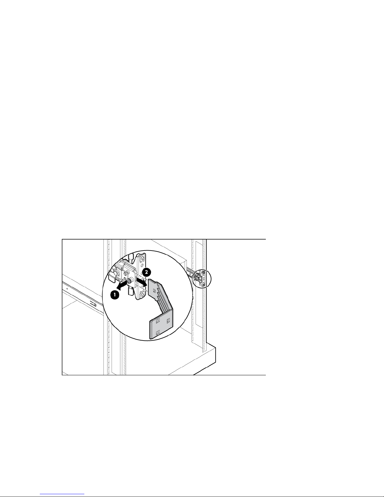
Access the product rear panel
Cable management arm with left-hand swing
To access the server rear panel:
1. Remove the cable arm retainer.
Operations 26
2.
Open the cable management arm.
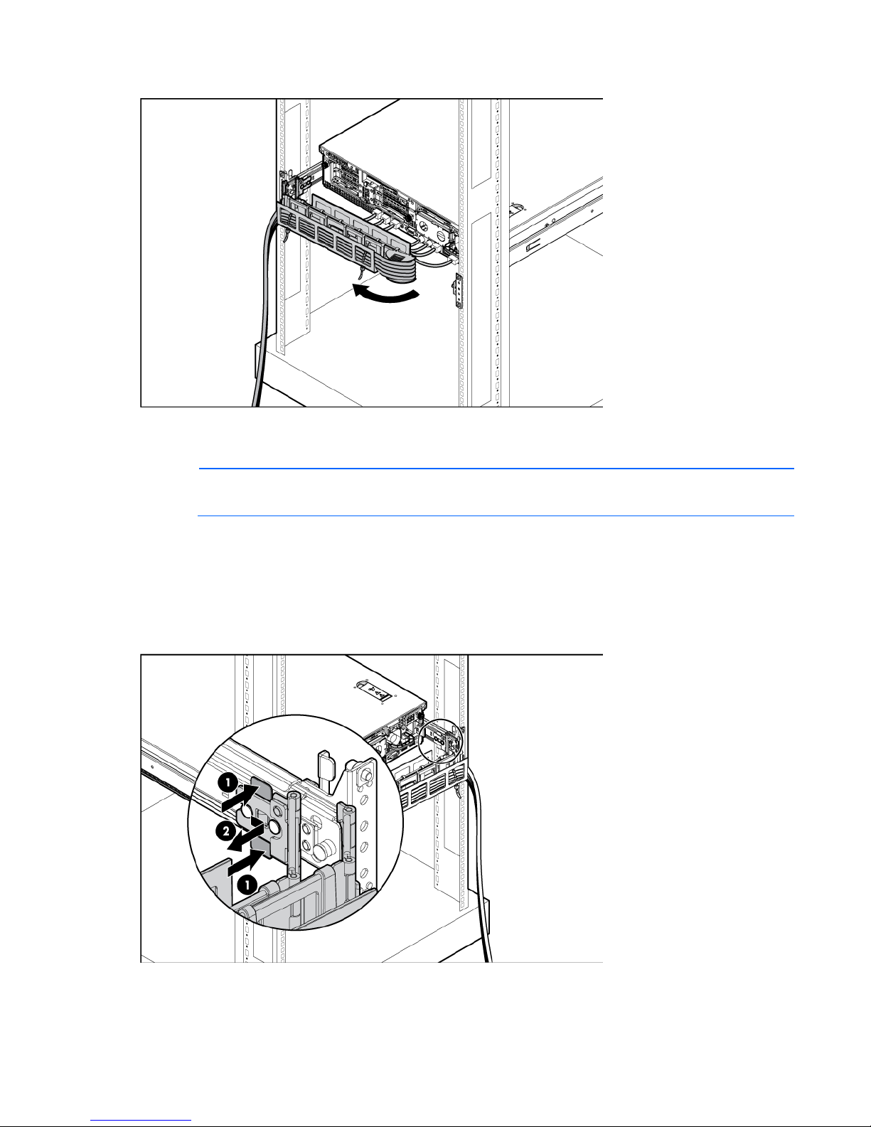
Cable management arm with right-hand swing
NOTE: To access some components, you may need to remove the cable management arm.
To access the product rear panel components, open the cable management arm:
1. Power down the server (on page 24).
2. Swing open the cable management arm.
3. Remove the cables from the cable trough.
4. Remove the cable management arm.
Operations 27
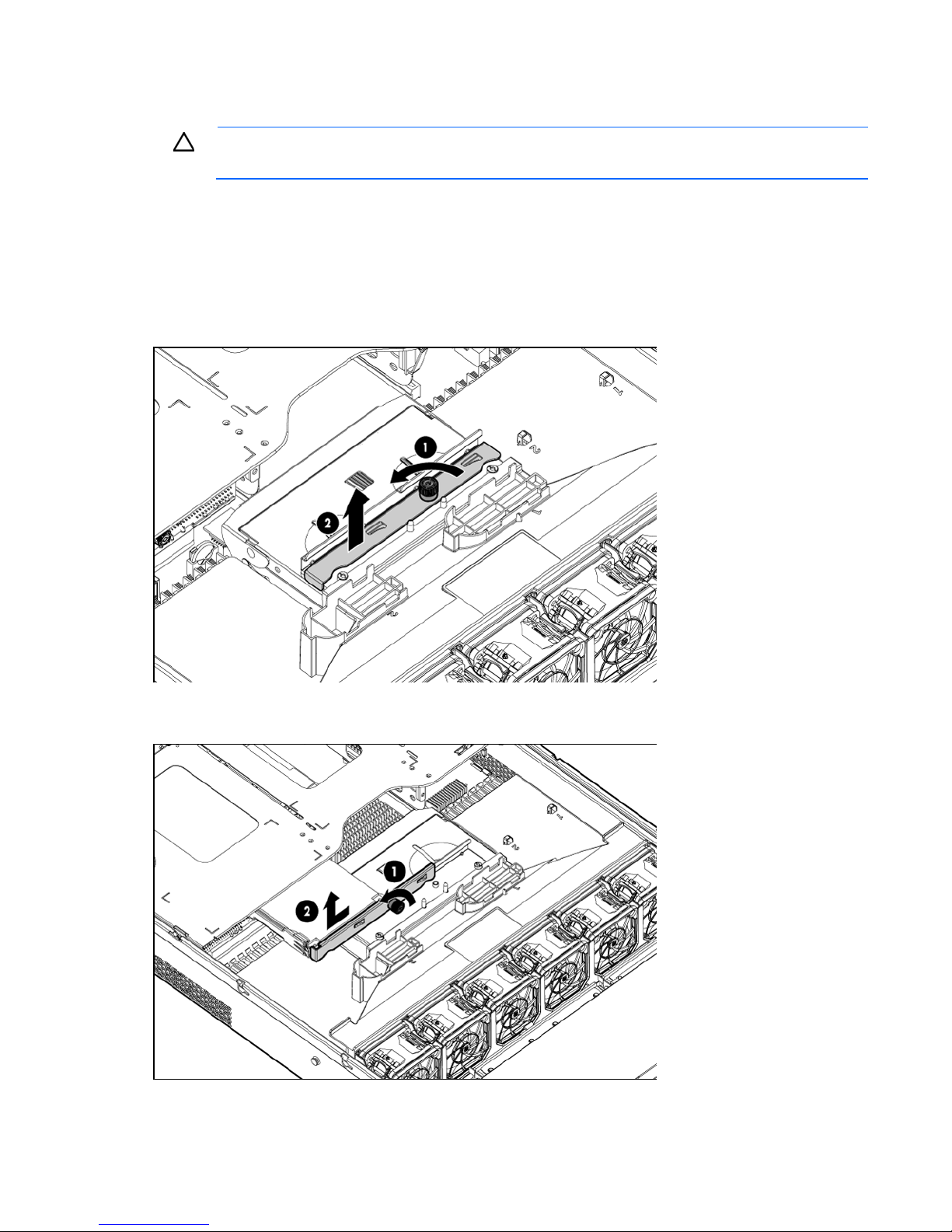
Remove the full-length expansion board retainer
CAUTION: To prevent damage to the server or expansion boards, power down the server and
1. Power down the server (on page 24).
2. Extend the server from the rack (on page 24).
3. Remove the access panel (on page 25).
4. Remove the full-length expansion board.
remove all AC power cords before removing or installing the PCI riser cage.
o If there are no full-length expansion board installed, remove the full-length expansion board retainer
as follows:
o If there are any full-length expansion boards installed, remove the full-length expansion board
retainer as follows:
Operations 28
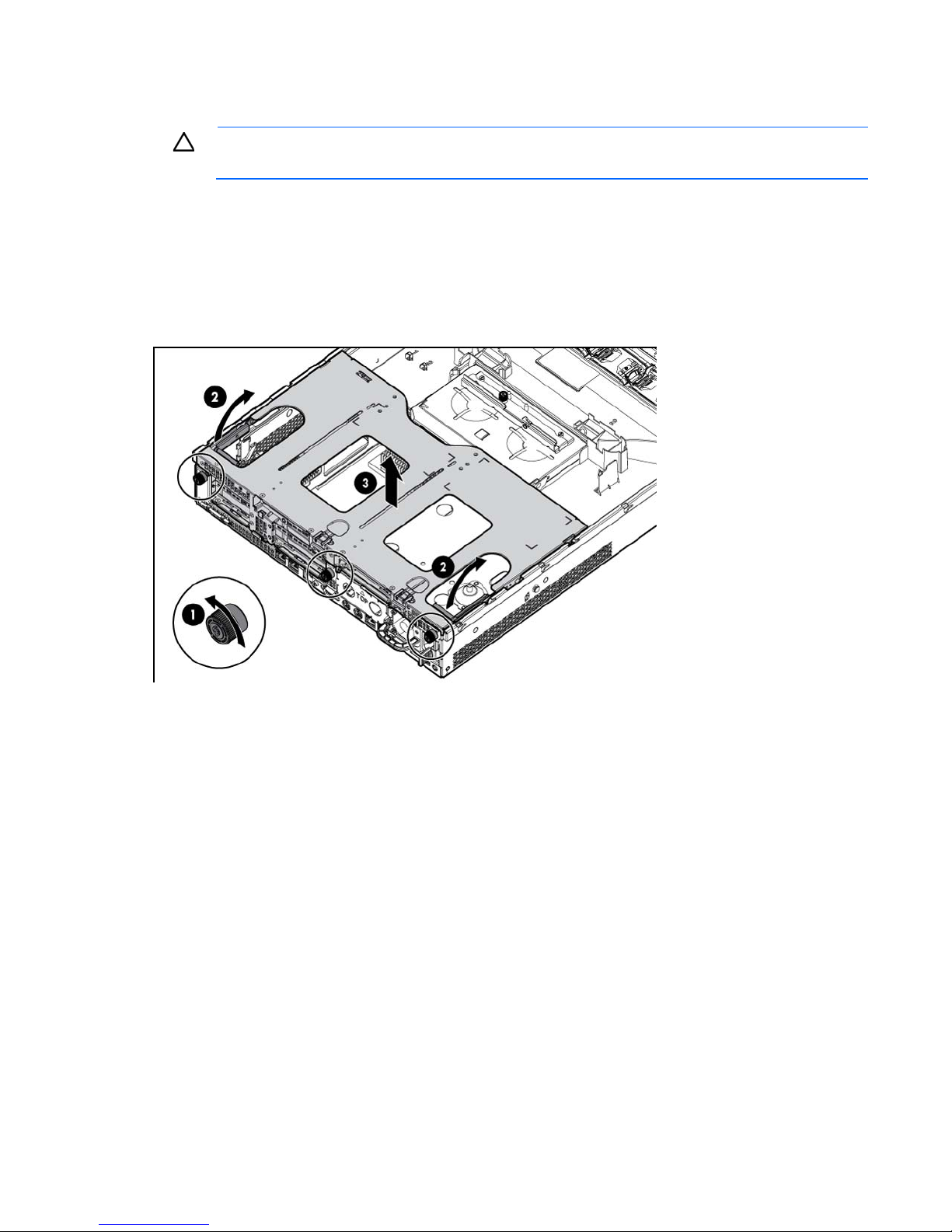
Remove the PCI riser cage
CAUTION: To prevent damage to the server or expansion boards, power down the server and
1. Power down the server (on page 24).
2. Extend the server from the rack (on page 24).
3. Remove the access panel (on page 25).
4. Remove the full-length expansion board retainer (on page 28) if any full-length expansion boards are
5. Remove the PCI riser cage.
remove all AC power cords before removing or installing the PCI riser cage.
installed.
Install the PCI riser cage
1. Power down the server (on page 24).
2. Extend the server from the rack (on page 24).
3. Remove the access panel (on page 25).
Operations 29
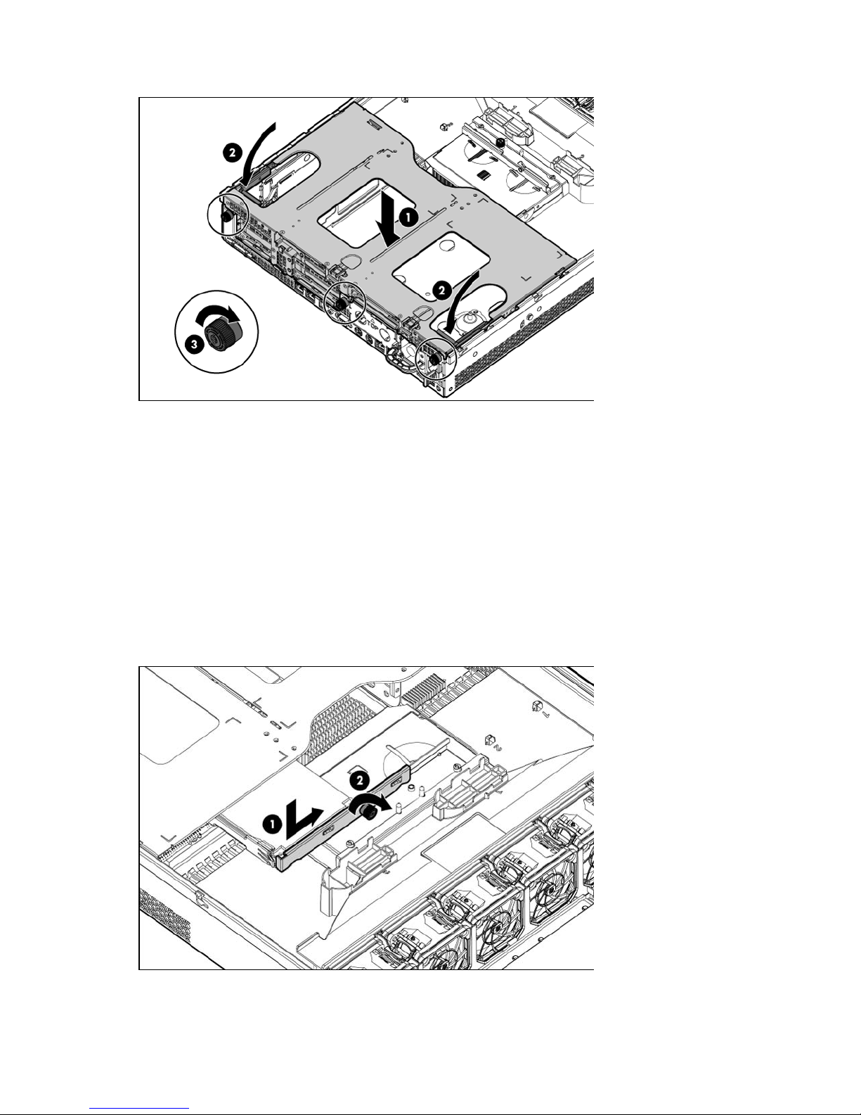
4.
Install the PCI riser cage.
5. Install the access panel (on page 26).
6. Install the server into the rack ("Installing the server into the rack" on page 35).
7. Power up the server (on page 24).
Install the full-length expansion board retainer
1. Power down the server (on page 24).
2. Extend the server from the rack (on page 24).
3. Remove the access panel (on page 25).
4. Install the PCI riser cage (on page 29).
5. Install the full-length expansion board retainer.
6. Install the access panel (on page 26).
Operations 30
 Loading...