

Page 1

HP ProLiant DL145 Generation 3 Server
Maintenance and Service Guide
Part number: 430047-004
Fourth Edition: April 2007
Page 2

Legal notices
© Copyright 2006, 2007 Hewlett-Packard Development Company, L.P.
The information contained herein is subject to change without notice. The only warranties for HP products and services are set forth in the
express warranty statements accompanying such products and services. Nothing herein should be construed as constituting an additional
warranty. HP shall not be liable for technical or editorial errors or omissions contained herein.
AMD, AMD Opteron, and combinations thereof are trademarks of Advanced Micro Devices, Inc.
Printed in the US
Part number: 430047-004
Fourth Edition: April 2007
2
Page 3

Contents
Illustrated parts catalog
Customer self-repair (CSR)......................................................................................................................... 4
Mechanical parts exploded view ............................................................................................................... 5
System components exploded view ............................................................................................................ 6
HP contact information ............................................................................................................................. 7
Before you contact HP .............................................................................................................................. 7
Removal and replacement procedures
Hardware configuration tools .................................................................................................................... 9
Hardware configuration warnings.............................................................................................................. 9
Symbols on equipment......................................................................................................................... 9
Rack warnings.................................................................................................................................. 10
Server warnings and precautions ........................................................................................................ 11
Hardware configuration information......................................................................................................... 11
Electrostatic discharge information ...................................................................................................... 11
Pre-installation procedures.................................................................................................................. 11
Post-installation procedures................................................................................................................. 12
Powering down the server....................................................................................................................... 12
Opening and closing the server ............................................................................................................... 12
Drive bay configuration .......................................................................................................................... 14
Cable routing diagrams ..................................................................................................................... 14
Optical drive .................................................................................................................................... 18
Hard drives ...................................................................................................................................... 20
System board ........................................................................................................................................ 29
Removing a system board .................................................................................................................. 29
Installing a system board.................................................................................................................... 30
System board configuration..................................................................................................................... 32
Processor ......................................................................................................................................... 32
Memory........................................................................................................................................... 38
Expansion boards ............................................................................................................................. 41
System battery .................................................................................................................................. 48
System fans ...................................................................................................................................... 50
Power supply unit (PSU) ..................................................................................................................... 54
Diagnostic tools
Overview of available diagnostic tools ..................................................................................................... 61
Connectors, buttons, and LEDs
Connectors and components ................................................................................................................... 62
Front panel components ..................................................................................................................... 62
Rear panel components ..................................................................................................................... 62
System board components.................................................................................................................. 63
Front panel board components ................................................................................................................ 65
Front panel board cable routing.......................................................................................................... 66
Status LED indicators .............................................................................................................................. 67
Front panel LED indicators.................................................................................................................. 67
Rear panel LED indicators .................................................................................................................. 68
System board LED indicators .............................................................................................................. 69
Physical and operating specifications
System unit............................................................................................................................................ 70
Memory................................................................................................................................................ 72
Processor .............................................................................................................................................. 72
Gigabit Ethernet controller ...................................................................................................................... 72
Index
Contents 3
Page 4
Illustrated parts catalog
This chapter provides the illustrated parts breakdown and spare parts lists for the HP ProLiant DL145 Generation
3 server. Information for contacting HP is also provided.
Customer self-repair (CSR)
What is customer self-repair?
HP's customer self-repair program offers you the fastest service under either warranty or contract. It enables HP to
ship replacement parts directly to you so that you can replace them. Using this program, you can replace parts at
your own convenience.
A convenient, easy-to-use program:
• An HP support specialist will diagnose and assess whether a replacement part is required to address a
system problem. The specialist will also determine whether you can replace the part.
• Replacement parts are express-shipped. Most in-stock parts are shipped the very same day you contact HP.
You may be required to send the defective part back to HP, unless otherwise instructed.
• Available for most HP products currently under warranty or contract. For information on the warranty
service, refer to the HP website
(http://h18004.www1.hp.com/products/servers/platforms/warranty/index.html
For more information about HP's customer self-repair program, contact your local service provider. For the North
American program, refer to the HP website (http://www.hp.com/go/selfrepair
Table 1 and Table 2 show the customer replaceable parts under the CSR program.
).
).
NOTE: Table items marked with an asterisk (*) are not shown in the figures.
Illustrated parts catalog 4
Page 5
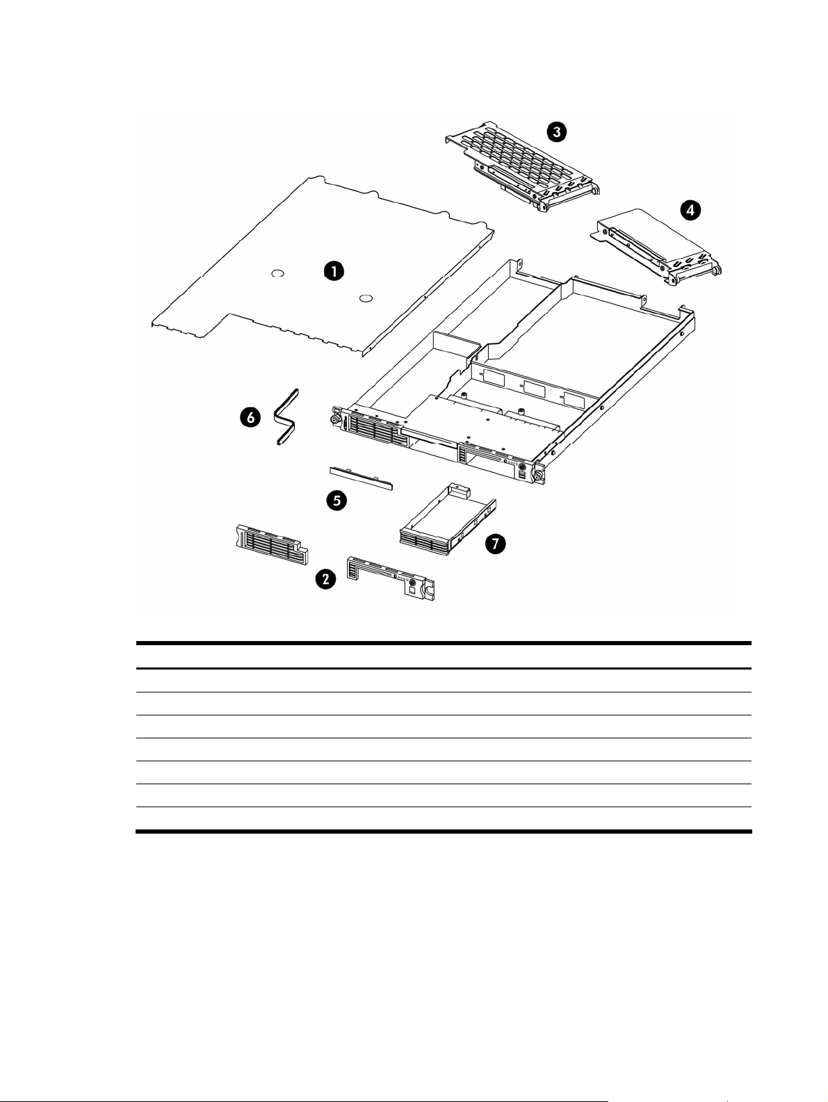
Mechanical parts exploded view
Figure 1 Mechanical parts exploded view
Table 1 Mechanical spare parts list
Item Description Spare Part Number Customer Self Repair
1 Top cover 434437-001 Mandatory
2 Front bezel 434423-001 Mandatory
3 Full-sized riser board assembly 434459-001 Mandatory
4 Low-profile riser board assembly 434458-001 Mandatory
5 Optical drive bay bezel 434436-001 Mandatory
6 Air baffle 434424-001 Mandatory
7 Non-hot-plug hard disk drive (HDD) carrier 434425-001 Mandatory
Illustrated parts catalog 5
Page 6
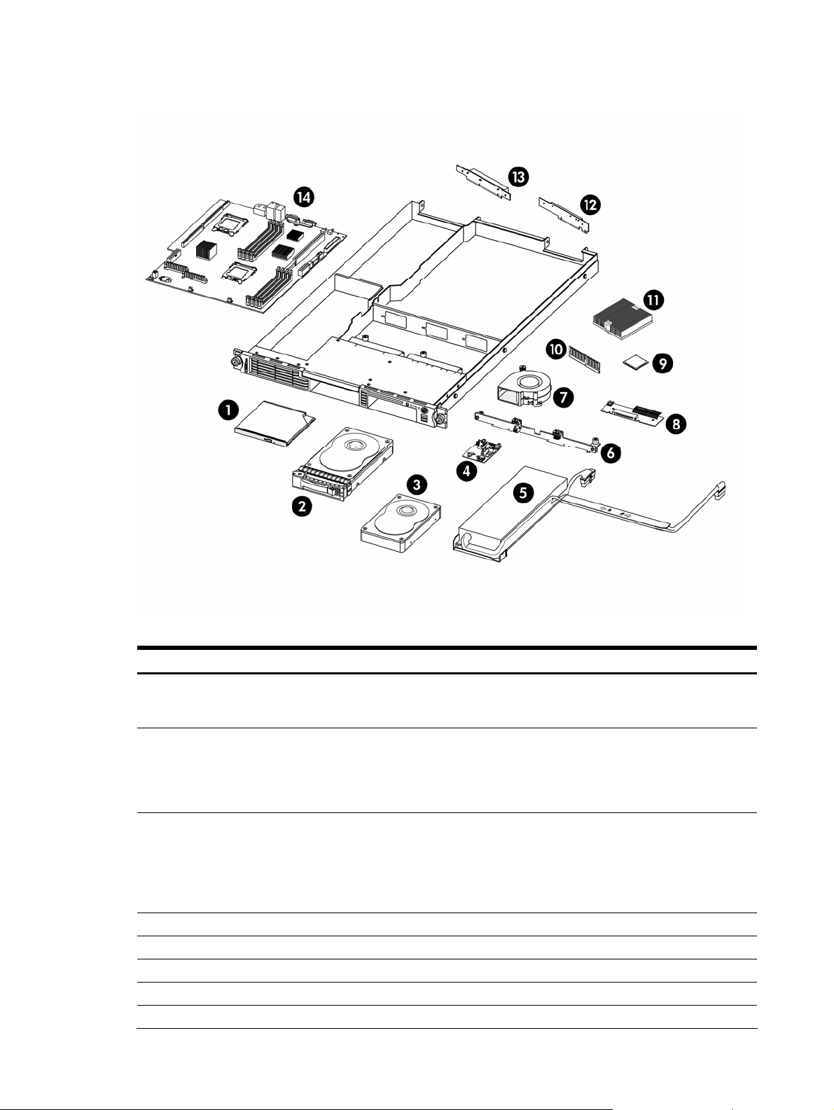
System components exploded view
Figure 2 System components exploded view
Table 2 System components spare parts list
Item Description Spare Part Number Customer Self Repair
1 Optical drive
a) DVD ROM drive
b) DVD/CD RW combo drive
2 Hot-plug SAS hard drive
a) 36 GB
b) 72 GB
c) 146 GB
d) 300 GB
3 Non-hot-plug SATA hard drive
a) 80 GB
b) 160 GB
c) 250 GB
d) 500 GB
e) 750 GB
4 Front panel board 434428-001 Mandatory
5 650 W power supply unit 434418-001 Mandatory
6 Hot-plug SATA/SAS backplane 434432-001 Mandatory
7 System fan module 434417-001 Mandatory
8 Optical drive docking board 434430-001 Mandatory
436951-001
436952-001
376593-001
376594-001
376595-001
432147-001
373311-001
399968-001
399969-001
404654-001
397377-001
Mandatory
Mandatory
Mandatory
Illustrated parts catalog 6
Page 7
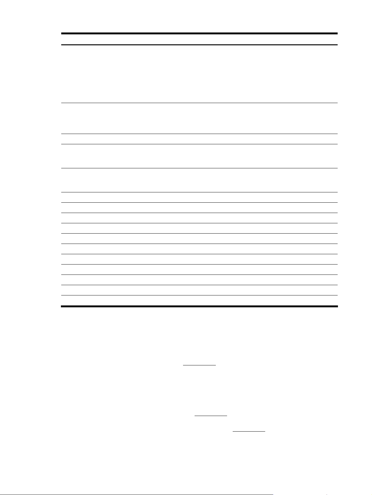
Table 2 System components spare parts list
Item Description Spare Part Number Customer Self Repair
9 Processor
a) 1.8 GHz, 68W AMD Opteron
b) 1.8 GHz, 95W AMD Opteron
c) 2.2 GHz, 68W AMD Opteron
d) 2.4 GHz, 68W AMD Opteron
e) 2.4 GHz, 95W AMD Opteron
f) 2.6 GHz, 95 W AMD Opteron
g) 2.8 GHz, 95 W AMD Opteron
10 Memory
a) 512 MB PC2-5300 DIMM
b) 1 GB MB PC2-5300 DIMM
c) 2 GB MB PC2-5300 DIMM
11 Processor heat sink 434433-001 Optional
12 Low-profile riser board
a) PCI Express x4 riser board
b) PCI-X riser board
13 Full-sized riser board
a) PCI Express x16 riser board
b) HTX riser board
14 System board 434426-001 Optional
PCI-X SATA/SAS controller board 403053-001 Mandatory
IDE data cable 434421-001 Mandatory
SATA data cable (long) 434461-001 Mandatory
SATA data cable (short) 434462-001 Mandatory
SAS cable assembly 385840-001 Mandatory
Front panel board LED cable assembly 434420-001 Mandatory
Front panel USB port 2.0 cable assembly 434419-001 Mandatory
Drive power cable assembly (non-hot-plug) 436538-001 Mandatory
Drive power cable assembly (hot-plug) 436539-001 Mandatory
3V 200-mAh internal lithium battery for system board 234556-001 Mandatory
434949-001
419473-001
419477-001
419479-001
419478-001
419480-001
439749-001
416355-001
416356-001
416357-001
434429-001
434434-001
434431-001
434435-001
Optional
Mandatory
Mandatory
Mandatory
HP contact information
For the name of the nearest HP authorized reseller:
• In the United States, call 1-800-345-1518.
• In Canada, call 1-800-263-5868.
• In other locations, refer to the HP website at www.hp.com.
For HP technical support:
• In North America:
• Call 1-800-HP-INVENT (1-800-474-6836). This service is available 24 hours a day, 7 days a week.
For continuous quality improvement, calls may be recorded or monitored.
• If you have purchased a Care Pack (service upgrade), call 1-800-633-3600. For more information
about Care Packs, refer to the HP website at www.hp.com.
• Outside North America, call the nearest HP Technical Support Phone Center. For telephone numbers for
worldwide Technical Support Centers, refer to the HP website at www.hp.com
Before you contact HP
Be sure to have the following information available before you call HP:
• Technical support registration number (if applicable)
.
Illustrated parts catalog 7
Page 8

• Product serial number
• Product model name and number
• Applicable error messages
• Add-on boards or hardware
• Third-party hardware or software
• Operating system type and revision level
Illustrated parts catalog 8
Page 9
Removal and replacement procedures
This chapter provides subassembly and module-level removal and replacement procedures for the HP ProLiant
DL145 Generation 3 server.
Review the specifications of a new component before installing it to make sure it is compatible with the server.
When you integrate new components into the system, record its model and serial number and any other pertinent
information for future reference. After completing any removal or replacement procedure, run the diagnostics
program to verify that all components operate properly.
Hardware configuration tools
When performing any hardware configuration procedure, you may need the following tools:
• T-15 Torx screwdriver
• Flat-blade screwdriver
• L-shaped wrench (ships with the server)
The following references and software tools may also be used:
• HP ProLiant DL145 Generation 3 Server Support CD
• IPMI Event Log
• Diagnostics software
NOTE: The figures used in this chapter to illustrate procedural steps are labeled numerically (1, 2, 3, and
so on). When these figures are used in substep items, the alphabetically labeled instructions correspond
to the numbered labels on the related figure (label 1 corresponds to step a, label 2 corresponds to step
b, and so on).
The procedures described in this chapter assume that the server is out of the rack and is positioned on a flat,
stable surface.
Hardware configuration warnings
Read the following sections before performing any servicing or troubleshooting procedure.
WARNING! Only authorized technicians trained by HP should attempt to repair this equipment. Because of the
complexity of the individual boards and subassemblies, no one should attempt to make repairs at the
component level or to make modifications to any printed wiring board. Improper repairs can create a safety
hazard.
CAUTION: Whenever installing hardware or performing maintenance procedures requiring access to internal
components, it is recommended that all server data be backed up to avoid loss.
Symbols on equipment
These symbols may be located on equipment in areas where hazardous conditions may exist.
WARNING! This symbol, in conjunction with any of the following symbols, indicates the presence of a
potential hazard. The potential for injury exists if warnings are not observed. Consult your documentation for
specific details.
This symbol indicates the presence of hazardous energy circuits or electric shock hazards. Refer all servicing to
qualified personnel.
WARNING! To reduce the risk of injury from electric shock hazards, do not open this enclosure. Refer all
maintenance, upgrades, and servicing to qualified personnel.
This symbol indicates the presence of electric shock hazards. The area contains no user or field serviceable
Removal and replacement procedures 9
Page 10
parts. Do not open for any reason.
WARNING! To reduce the risk of injury from electric shock hazards, do not open this enclosure.
This symbol on an RJ-45 receptacle indicates a network interface connection.
WARNING! To reduce the risk of electric shock, fire, or damage to the equipment, do not plug telephone or
telecommunications connectors into this receptacle.
This symbol indicates the presence of a hot surface or hot component. If this surface is contacted, the potential
for injury exists.
WARNING! To reduce the risk of injury from a hot component, allow the surface to cool before touching.
These symbols, on power supplies or systems, indicate that the equipment is supplied by multiple
sources of power.
WARNING! To reduce the risk of injury from electric shock, remove all power cords to completely
disconnect power from the system.
This symbol indicates that the component exceeds the recommended weight for one individual to handle safely.
WARNING! To reduce the risk of personal injury or damage to the equipment, observe local occupational
health and safety requirements and guidelines for manual material handling.
Rack warnings
WARNING! To reduce the risk of personal injury or damage to equipment, always ensure that the rack is
adequately stabilized before extending a component outside the rack. A rack may become unstable if more
than one component is extended for any reason. Extend only one component at a time.
WARNING! To reduce the risk of personal injury or damage to the equipment, be sure that:
WARNING! When installing the server in a Telco rack, make certain that the rack frame is adequately secured
to the building structure at the top and bottom.
WARNING! To reduce the risk of personal injury or damage to the equipment, at least two people are needed
to safely unload the rack from the pallet. An empty 42U rack weighs 115 kg (253 lb), is more than 2.1 m (7 ft)
tall, and may become unstable when being moved on its casters. Do not stand in front of the rack as it rolls
down the ramp from the pallet. Handle the rack from both sides.
• The leveling jacks are extended to the floor.
• The full weight of the rack rests on the leveling jacks.
• The stabilizers are attached to the rack, if it is a single rack installation.
• The racks are coupled together in multiple rack installations.
CAUTION: This ProLiant server is intended for rack-mount operation. The server bezel is made from glossy
material. For safety purposes, do not place the server in the visual field of users to prevent any accidents
arising from light bouncing off the bezel’s surface.
ACHTUNG: Entsprechend der Bildschirmabeitsplatzverordnung, darf das Gerät nicht im Gesichtsfeld des
Bedieners aufgestellt werden, da das Gehäuse eine glänzende Front aufweist.
Removal and replacement procedures 10
Page 11

Server warnings and precautions
WARNING! Hazardous voltages are present inside the server. Always disconnect AC power from the server
and other associated assemblies while working inside the unit. Serious injury may result if this warning is not
observed.
WARNING! To reduce the risk of personal injury from hot surfaces, allow the hot-plug drives and the internal
system components to cool before touching them.
WARNING! To reduce the risk of electric shock or damage to the equipment:
• Do not disable the power cord grounding plug. The grounding plug is an important safety
feature.
• Plug the power cord into a grounded (earthed) electrical outlet that is easily accessible at all
times.
• Disconnect all power cords to completely remove power from the system.
CAUTION: Protect the server from power fluctuations and temporary interruptions with a regulating
uninterruptible power supply (UPS). This device protects the hardware from damage caused by power surges
and voltage spikes and keeps the system in operation during a power failure.
CAUTION: The server must always be operated with the system top cover closed. Proper cooling is not
achieved if the system top cover is removed.
Hardware configuration information
Electrostatic discharge information
Proper packaging and grounding techniques are necessary precautions to prevent damage. To prevent
electrostatic damage, observe the following precautions:
• Transport products in static-safe containers such as conductive tubes, bags, or boxes.
• Keep electrostatic-sensitive parts in their containers until they arrive at static-free stations.
• Cover workstations with approved static-dissipating material. Use properly grounded (earthed) tools and
equipment and a wrist strap connected to the work surface.
• Keep the work area free of nonconductive materials, such as ordinary plastic assembly aids and foam
packing.
• Make sure that you are always properly grounded (earthed) when touching a static-sensitive component or
assembly.
• Avoid touching pins, leads, or circuitry.
• Always place drives with the Printed Circuit Board (PCB) assembly-side down.
• Use conductive field service tools.
Pre-installation procedures
Perform the steps below before you open the server or before you remove or replace any component:
WARNING! Failure to properly turn off the server before you open the server or before you start removing or
installing hardware components may cause serious damage as well as bodily harm.
1. Turn off the server and all the peripherals connected to it.
Refer to the “Powering down the server” section on page 12 for detailed instructions on how to completely
power down the server.
2. Disconnect the AC power cord from the power supply cable socket located on the server rear panel to
eliminate the risk of electrical shock.
Removal and replacement procedures 11
Page 12

3. Remove the top cover by following the procedure described in the “Opening and closing the server”
section on page 12.
4. Follow the ESD precautions listed in the “Electrostatic discharge information” section on page 11 when
handling a server component.
IMPORTANT: To streamline the configuration process, read through the entire installation and removal
procedures first and make sure you understand them before you before you begin.
Post-installation procedures
Perform the steps below after installing or removing a server component:
1. Be sure all components are installed according to the described step-by-step instructions.
2. Check to make sure you have not left loose tools or parts inside the server.
3. Reinstall any expansion boards, riser board assemblies, peripherals, board covers, brackets, and system
cables that you have removed.
4. Reinstall the top cover by following the procedure described in the “Opening and closing the server”
section on page 12.
5. Connect all external cables and the AC power cord to the system.
Route the cables properly through the available cable management arrangement.
6. Press the power button on the front panel to turn on the server.
Powering down the server
The server does not completely power down when the power button is pressed. The power button toggles
between On and Standby. The standby position removes power from most electronics and the drives, but some
internal circuitry remains active. To completely remove all power from the system, disconnect all power cords
from the server.
To power down the server:
1. Shut down server as directed by the operating system documentation.
2. Press the power button to toggle to Standby.
This places the server in standby mode and changes the power LED indicator to amber. In this mode, the
main power supply output is disabled. Standby does not completely disable or remove power from the
system.
3. Disconnect the AC power cord from the AC outlet and then from the server.
4. Be sure that the power LED indicator is turned off and that the fan noise has stopped.
5. Disconnect all external peripheral devices from the server.
Opening and closing the server
The top cover is detachable. You need to remove this cover before you can remove or replace a server
component.
To open the server:
1. Perform steps 1 and 2 of the pre-installation procedures on page 11.
2. Detach the top cover from the chassis:
a. Loosen the captive screw on the rear panel.
To loosen the screw, HP recommends using the L-shaped wrench that ships with the server.
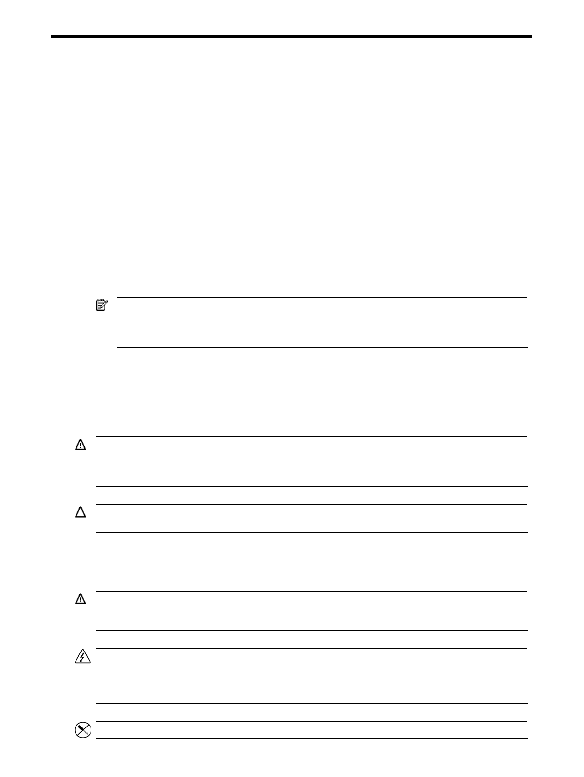
b. Slide the cover approximately 1.25 cm (0.5 in) toward the rear of the unit, then lift the cover away
from the chassis.
You can use the two circular grips on the top cover to help you slide the cover more easily.
Removal and replacement procedures 12
Page 13
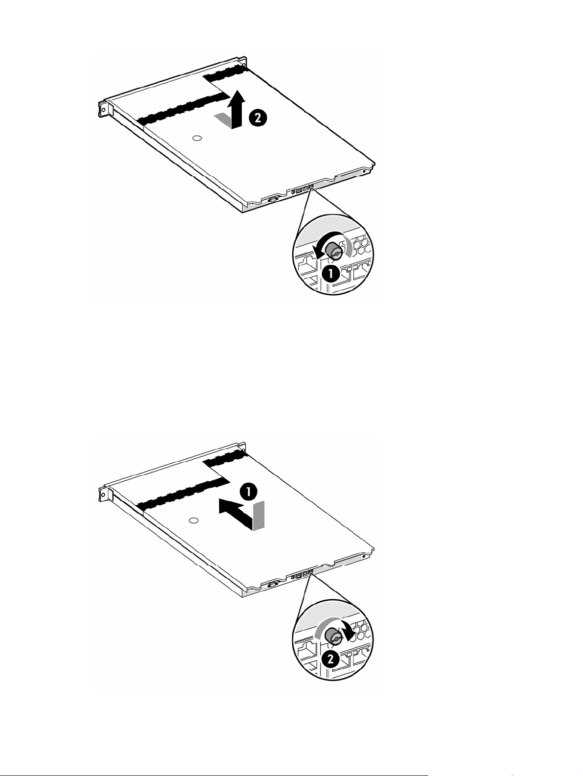
Figure 3 Removing the top cover
3. Place the top cover in a safe place for reinstallation later.
To reinstall the top cover:
1. Perform steps 1 to 3 of the post-installation procedures described on page 12.
2. Reinstall the top cover:
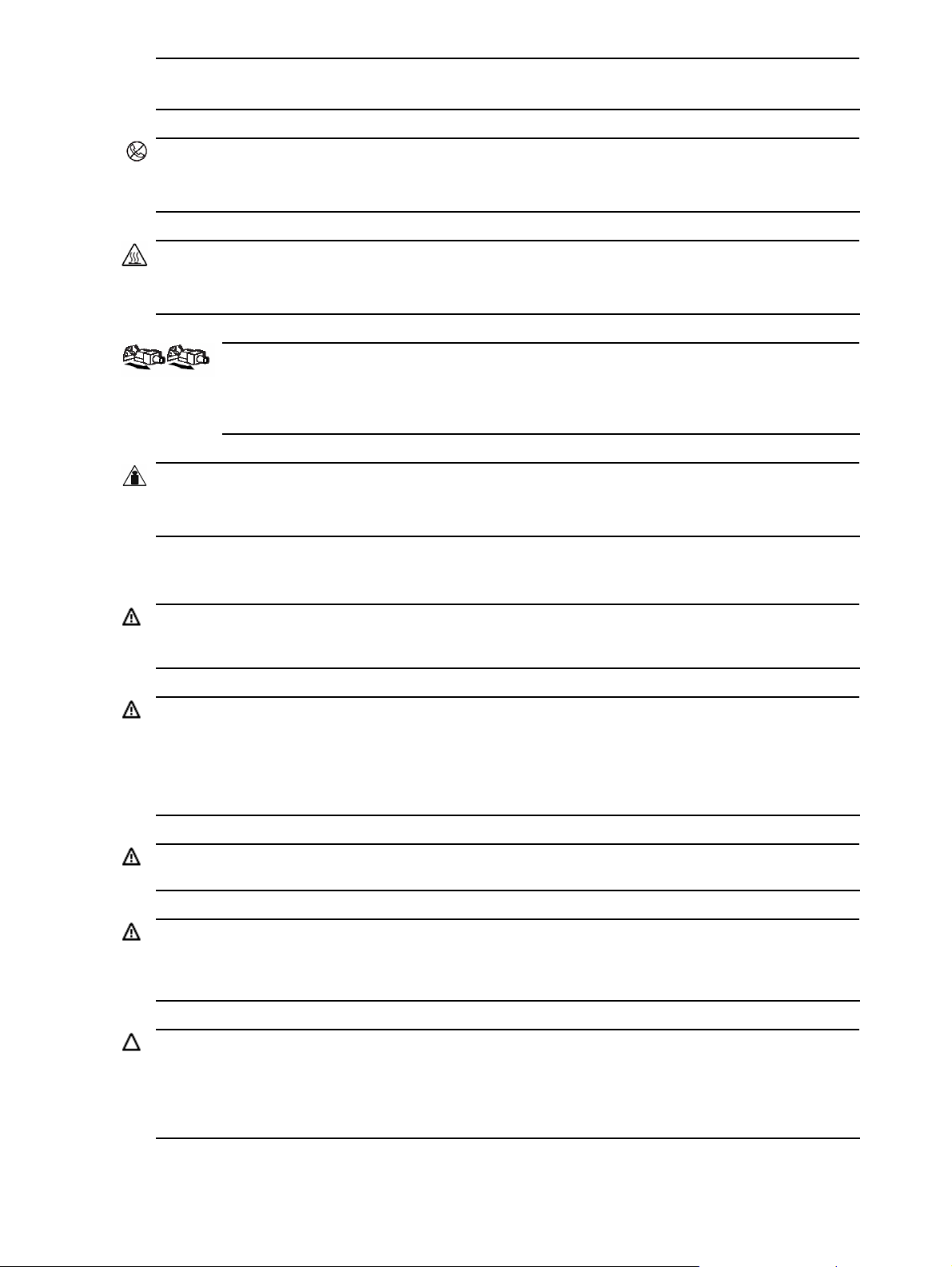
a. Place the cover on the chassis approximately 1.25 cm (0.5 in) toward the rear of the unit, then slide the
cover forward into place.
b. Tighten the captive screw on the rear panel.
To tighten the screw, HP recommends using the L-shaped wrench that ships with the server.
Figure 4 Reinstalling the top cover
3. Perform steps 5 and 6 of the post-installation procedure on page 12.
Removal and replacement procedures 13
Page 14
Drive bay configuration
The server supports three drive bays — two drive bays for hard disk drives and one drive bay for a 9.5-mm
optical drive.
Go to the HP website at http://www.hp.com/
information on supported hard drives and optical drives.
Figure 5 Drive bay configuration
and refer to the options list for this server model for the latest
Item Description
1 Optical drive bay
2 Hard disk drive (HDD) bay 1
3 HDD bay 2
Cable routing diagrams
Figure 6 to Figure 8 show the cable routing for the optical drive as well as the SATA and SAS hard drives. For
detailed cable routing procedures for each type of drive, refer to the corresponding steps in the drive
configuration sections later in this chapter.
CAUTION: Route the drive cables neatly. If possible, follow the pre-installed cable bundles in the chassis. The
cables should be routed in a position where they will not be pinched or crimped by the top cover, and they
should not hamper proper airflow inside the chassis.
Removal and replacement procedures 14
Page 15
Optical drive cable routing
Figure 6 Optical drive cable routing
Item Description Connections
1 Drive power cable • P41 on the system board
• Power connector on the optical drive docking board
• Power connectors on any installed non-hot-plug SATA hard drives or the
hot-plug SATA/SAS backplane, if installed
2 IDE data cable • J7 on the system board
• Data connector on the optical drive docking board
Removal and replacement procedures 15
Page 16
Hard drive cable routing
Non-hot-plug SATA hard drive cable routing
Figure 7 Non-hot-plug SATA hard drive cable routing
Item Description Connections
1 Drive power cable • P41 on the system board
• Power connector on each installed non-hot-plug SATA hard drive
• Power connector on the optical drive docking board, if installed
2 SATA data cables • P19 or P23 on the system board
• Data connector on each installed non-hot-plug SATA hard drive
Hot-plug SATA/SAS hard drive cable routing
Figure 8 shows the hot-plug hard drive cable routing when the server has a low-profile PCI Express x4 or PCI-X
hot-plug SATA/SAS controller board installed. Figure 9 shows the hard drive cable routing when the server has a
full-sized PCI Express x16 hot-plug SATA/SAS controller board installed.
Removal and replacement procedures 16
Page 17
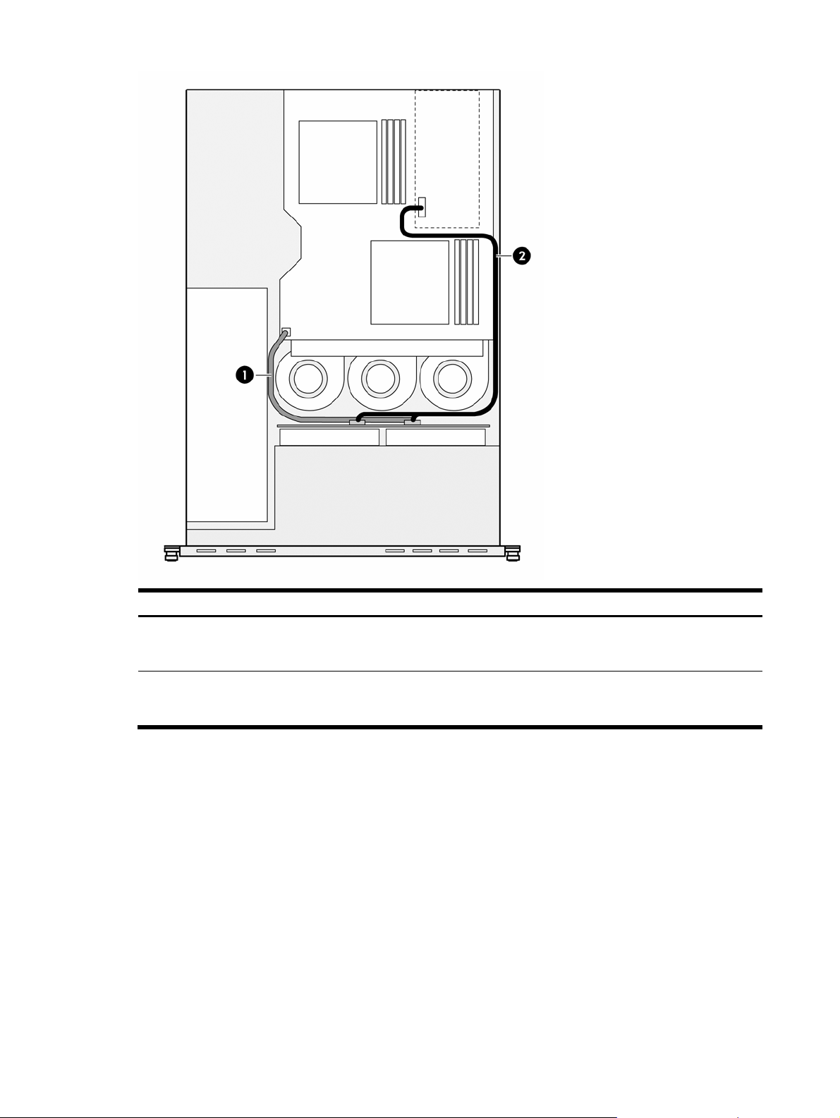
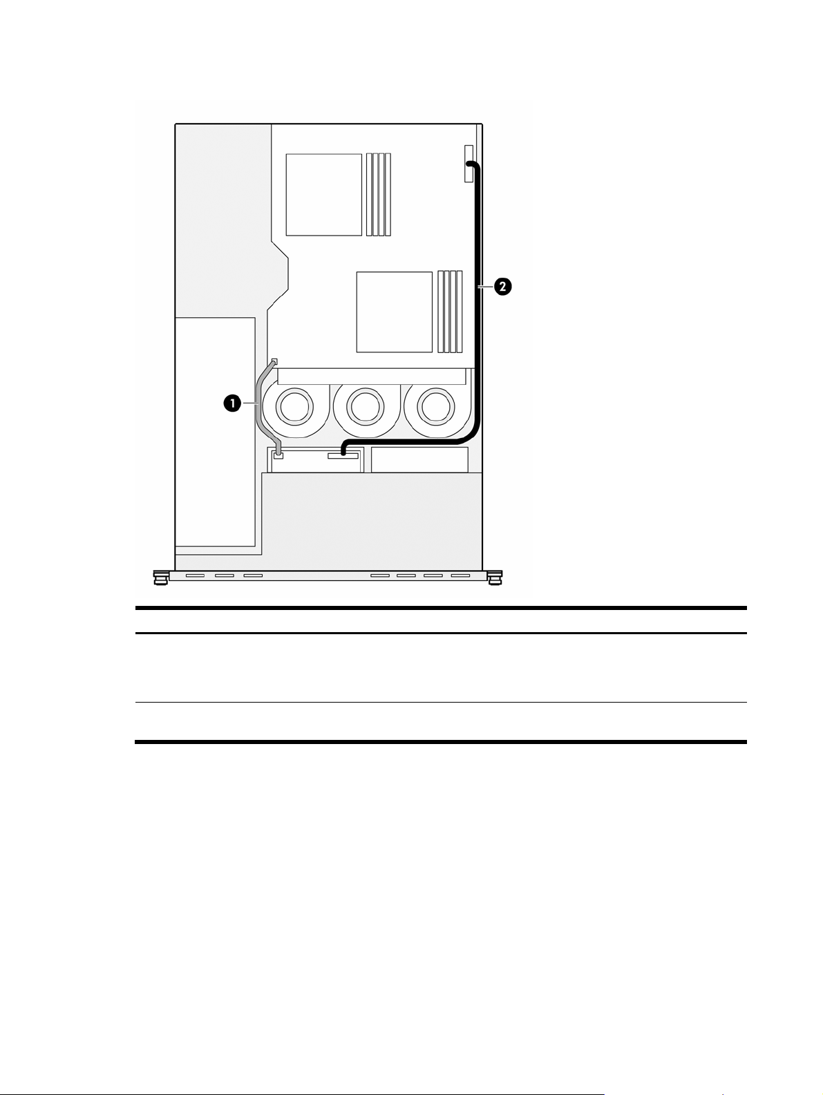
Figure 8 Hot-plug SATA/SAS hard drive cable routing with a low-profile controller board
Item Description Connections
1 Hot-plug SATA/SAS backplane power
cable
• P41 on the system board
• Power connectors on the hot-plug SATA/SAS backplane
• Power connector on the optical drive docking board, if installed
2
Hot-plug SATA/SAS cable assembly
• Data connector on the hot-plug SATA/SAS controller board
• Data connectors and the LED connector on the hot -plug SATA/SAS
backplane
Removal and replacement procedures 17
Page 18
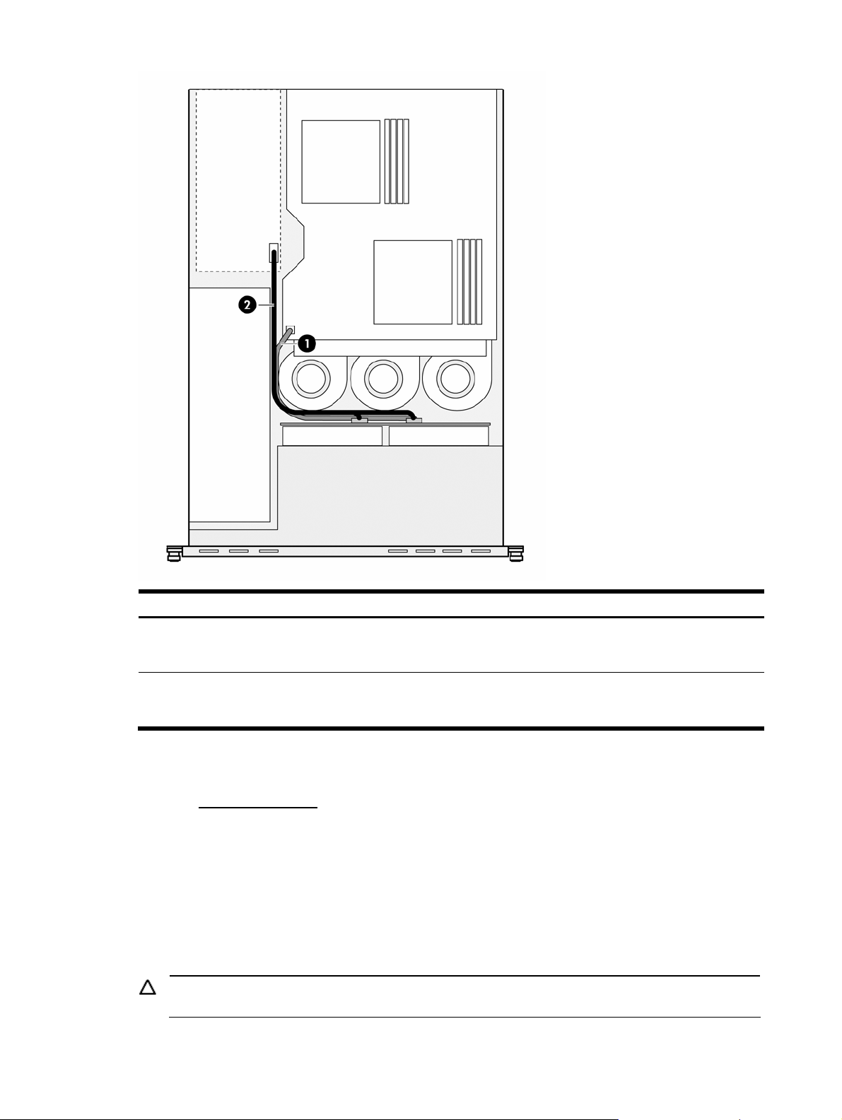
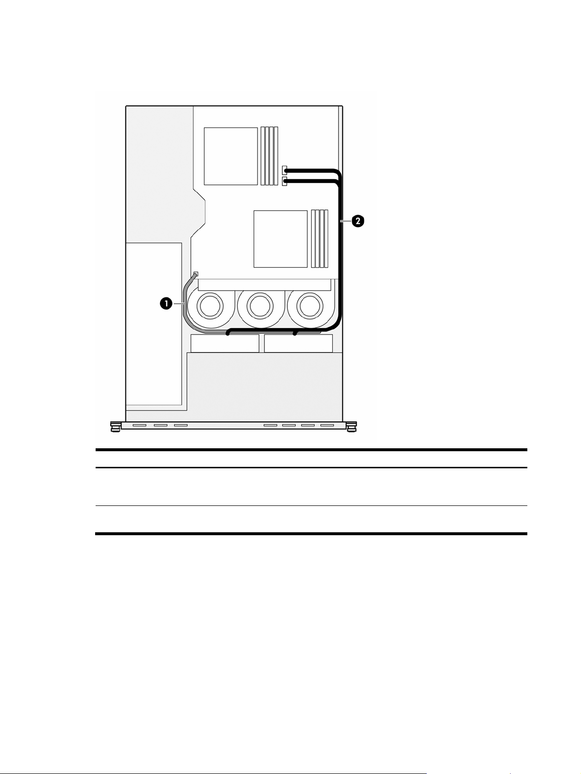
Figure 9 Hot-plug SATA/SAS hard drive cable routing with a full-sized controller board
Item Description Connections
1 Hot-plug SATA/SAS backplane power
2
Optical drive
The optical drive bay supports the installation of a 9.5-mm CD-ROM or CD/DVD combo drive. Go to the HP
website at http://www.hp.com/
drives.
To install a CD-ROM or CD/DVD combo drive:
1. Perform the pre-installation procedures described on page 11.
2. Remove the optical drive bay bezel from the chassis:
a. Push down on the two bezel tabs above the optical drive bay on the non-removable section of the
b. Remove the bezel from the optical drive bay.
cable
Hot-plug SATA/SAS cable assembly
and refer to the options list for this server model for a list of supported optical
chassis top cover.
Store the bezel for reassembly later.
• P41 on the system board
• Power connectors on the hot-plug SATA/SAS backplane
• Power connector on the optical drive docking board, if installed
• Data connector on the hot-plug SATA/SAS controller board
• Data connectors and the LED connector on the hot-plug SATA/SAS
backplane
CAUTION: Do not discard the bezel. If the optical drive is removed in the future, this bezel must be
reinstalled in the chassis for the proper cooling of the system.
Removal and replacement procedures 18
Page 19
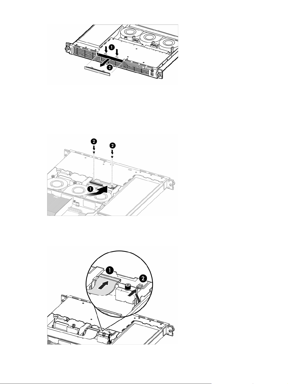
Figure 10 Removing the optical drive bay bezel
3. Install the optical drive docking board:
a. Hold the docking board at a slight angle to the chassis, then carefully slide it into place under the non-
removable section of the chassis top cover and on top of the optical drive bay.
Be sure not to scratch any docking board components on the non-removable section of the chassis top
cover or on the captive thumbscrew on HDD bay 1 beneath the optical drive bay.
b. Attach the docking board to the chassis with the two screws included in the option kit.
Figure 11 Installing the optical drive docking board
4. Connect the IDE data cable and the small drive power cable to the docking board.
Both cables are already connected to the system board and routed to the optical drive bay within the
chassis.
Figure 12 Connecting the optical drive cables
5. Remove the new optical drive from its protective packaging.
6. Align the optical drive with the optical drive bay, then push the drive fully into the drive bay.
Make sure the drive is not upside down.
Removal and replacement procedures 19
Page 20
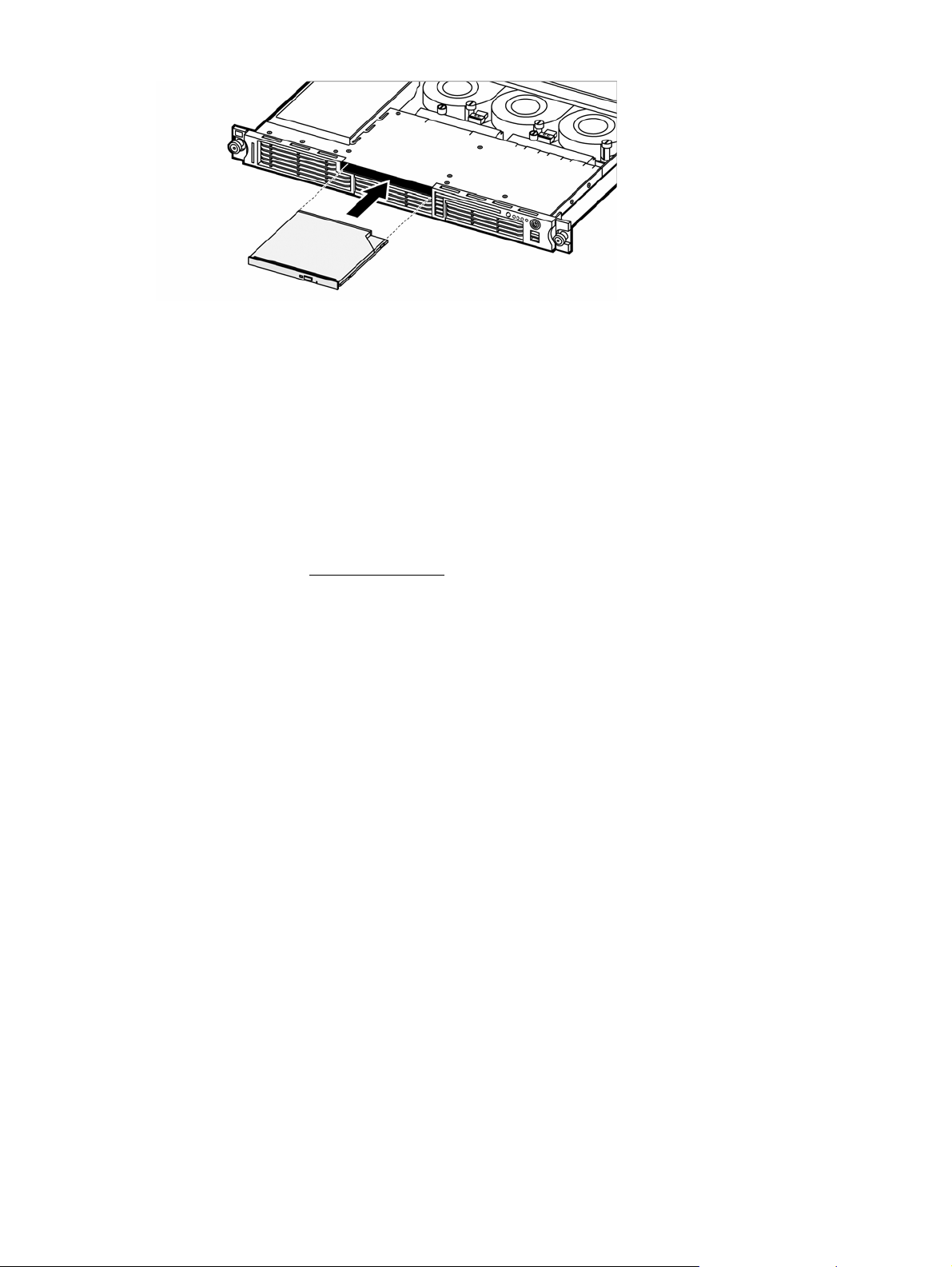
Figure 13 Installing an optical drive
7. Perform the post-installation procedures described on page 12.
Hard drives
The server has two HDD bays that support both non-hot-plug SATA hard drives and hot-plug SATA or SAS hard
drives. You can add a hard drive to an empty HDD bay by installing an appropriate drive option; servers
configured as non-hot-plug systems cannot use hot-plug hard drives, and servers configured as hot-plug systems
cannot use non-hot-plug hard drives.
The non-hot-plug SATA drive options include only the hard drive. Install these drive options using the HDD
carriers and mounting screws included with a server configured for non-hot-plug drives.
The hot-plug SATA and SAS drive options are pre-installed in hot-plug HDD carriers. Use these hot-plug drive
assemblies to replace any installed hardware in an HDD bay of a server configured for hot-plug drives. A hotplug HDD bay may contain a blank drive carrier or a hot-plug drive assembly.
Go to the HP website at http://www.hp.com/ and refer to the options list for this server model for the latest
information on supported hard drives.
Hard drive installation guidelines
Observe the following important guidelines when installing hard drives:
• Install only hard drive models specified for your ProLiant server. Installing unsupported hard drives may
damage the system by consuming power and generating heat in excess of the operating tolerance of the
server. This condition may result in a loss of system and/or data integrity.
• Install non-hot-plug SATA hard drives in the HDD carriers included with the server. Use four of the six HDD
screws pre-installed in each of the two HDD carriers.
Removal and replacement procedures 20
Page 21
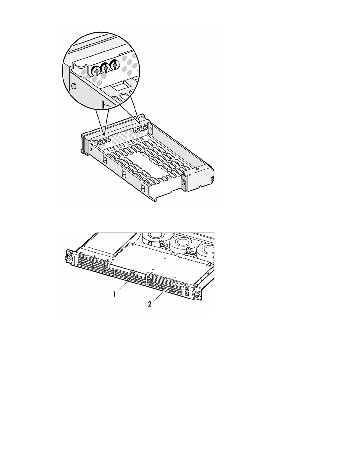
Figure 14 Pre-installed screw locations in the non-hot-plug HDD carrier
• Hard drives installed in the server are labeled as drive 1 and drive 2 from left to right when viewed from
the front of the server.
Figure 15 HDD bay locations
Removing a non-hot-plug SATA hard drive
If you intend to replace a non-hot-plug SATA hard drive with another non-hot-plug SATA hard drive, use the HDD
carrier and screws you remove from the old drive to install the new drive.
To remove a non-hot-plug SATA hard drive:
1. Perform the pre-installation procedures described on page 11.
2. Disconnect the data and power cables from the rear of the hard drive.
3. Remove the HDD carrier from the chassis:
a. Loosen the screw that secures the HDD carrier to the chassis.
b. Push the HDD carrier toward the front of the chassis, then slide it out completely.
Removal and replacement procedures 21
Page 22
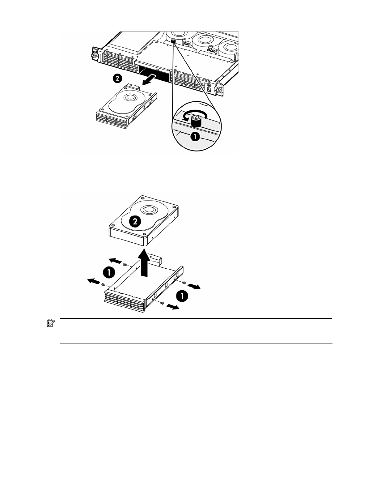
Figure 16 Removing a non-hot-plug SATA hard drive from the chassis
4. Remove the hard drive from the HDD carrier:
a. Remove the four mounting screws that secure the hard drive to the HDD carrier.
b. Remove the hard drive from the HDD carrier.
Figure 17 Removing a non-hot-plug SATA hard drive from the HDD carrier
IMPORTANT: If you remove a hard drive and do not plan to install a new one immediately, you must reinstall
the mounting screws at their pre-installed location for future use, then reinstall the HDD carrier in the chassis to
ensure the proper cooling of the system. Then perform the post-installation procedures described on page 12.
Installing a non-hot-plug SATA hard drive
1. Perform the pre-installation procedures described on page 11.
2. Select a drive bay for the new hard drive.
If the drive bay is occupied, remove the currently installed drive by following the procedures described in
the “Removing a non-hot-plug SATA hard drive” section on page 21.
If the drive bay is empty, perform step 3 in the “Removing a non-hot-plug SATA hard drive” section
described on page 21, then remove four mounting screws from the HDD carrier. You will use these screws
to install the new drive.
3. Install the new hard drive in the HDD carrier:
a. Align the new hard drive on the HDD carrier.
If you are installing the new drive in a previously occupied drive bay, use the HDD carrier and
mounting screws you removed from the old drive.
Removal and replacement procedures 22
Page 23
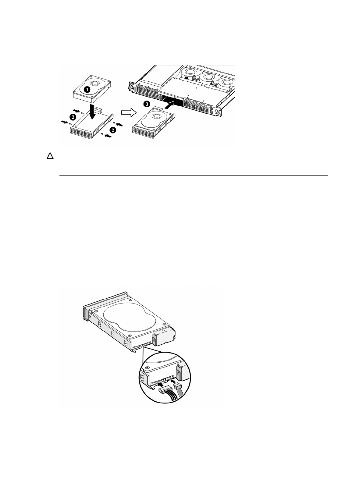
If you are installing the new drive in an empty drive bay, use the HDD carrier and mounting screws you
removed from that drive bay.
b. Secure the hard drive to the HDD carrier with the four mounting screws.
c. Slide the hard drive assembly into the chassis.
Figure 18 Installing a non-hot-plug SATA hard drive in the HDD carrier and chassis
CAUTION: Route the SATA data cables neatly. Follow the bundle of cables along the right side of the chassis.
The cables should be routed in a position where they will not be pinched or crimped by the top cover, and
they should not hamper proper airflow inside the chassis.
4. Route the SATA data cable:
a. Connect the SATA data cable to an open SATA connector on the system board (P19 or P23) if it is not
already connected.
b. Route the SATA data cable between the processor 2 socket DIMM slots and the PCI Express x4 slot to
the right edge of the chassis (as viewed from the front of the server).
c. Route the SATA data cable toward the front of the chassis, following the bundled cables.
d. Route the SATA data cable between the drive bays and the system fans.
5. Connect the SATA data and power cables to their corresponding connectors on the rear of the new drive.
If necessary, you can remove the system fans to allow easier access to the drive connectors. Perform steps 2
to 4 in the “Removing a system fan” section described on page 51 to remove each system fan, then
continue with this procedure.
Figure 19 Connecting the SATA data and power cables to a non-hot-plug hard drive
6. Check that all cables are clear of the HDD carrier and are properly routed to their corresponding
connectors, then tighten the screw that secures the hard drive assembly to the chassis.
If you removed the system fans in the previous step, perform steps 1 to 3 in the “Installing a system fan”
section described on page 53.
7. Perform the post-installation procedures described on page 12.
Removal and replacement procedures 23
Page 24

8. Set up the SATA configuration.
For detailed procedures, refer to the Server Support CD or to the operating system documentation.
Removing a hot-plug SATA/SAS drive assembly
This procedure assumes the hot-plug SATA/SAS backplane is already installed. See the “Installing the hot-plug
SATA/SAS backplane” section described on page 26 for more details.
To remove a hot-plug SATA/SAS drive assembly from the server:
1. Push the button on the front of the HDD carrier you want to remove to release the carrier latch, then pull the
carrier latch to its open position.
2. Remove the hot-plug drive assembly from the chassis.
Installing a hot-plug SATA/SAS drive assembly
This procedure assumes the hot-plug SATA/SAS backplane is already installed. See the “Installing the hot-plug
SATA/SAS backplane” section described on page 26 for more details.
To install a hot-plug SATA/SAS drive assembly in the server:
1. Prepare the HDD bay for installation:
• If you are replacing a currently installed hot-plug drive with a hot-plug drive option pre-installed in an
HDD carrier, perform the procedure in the “Removing a hot-plug SATA/SAS drive assembly” section on
page 24.
Because the new hot-plug hard drive is pre-installed in an HDD carrier, you do not need to reuse the
HDD carrier that you are removing from the server.
• If you are replacing a currently installed hot-plug drive with a SATA or SAS drive that is not pre-
installed in an HDD carrier, perform the procedure in the “Replacing a hot-plug SATA or SAS hard
drive” section on page 25.
• If the HDD bay contains a blank drive carrier, squeeze the two center tabs on the bezel toward each
other, then remove the carrier from the chassis.
2. If the carrier latch on the HDD carrier you want to install is not already open, push the button on the front of
the HDD carrier, then pull the carrier latch to its open position.
3. Align the hot-plug drive assembly with the open drive bay and push the assembly into the drive bay until it
stops.
Figure 20 Installing a hot-plug SATA/SAS drive assembly
The metal tab at the front of the HDD bay should fit inside the notch in the hinge of the carrier latch.
Removal and replacement procedures 24
Page 25

Figure 21 Aligning the latch on a hot-plug SATA/SAS drive assembly
4. Press the HDD carrier latch inward until it clicks.
The latch should pull the hot-plug drive assembly fully into the chassis. The carrier latch should pull against
the metal tab on the HDD bay only, not on the front bezel on the chassis.
Figure 22 Closing the latch on a hot-plug SATA/SAS drive assembly
Replacing a hot-plug SATA or SAS hard drive
This procedure assumes the hot-plug SATA/SAS backplane is already installed. See the “Installing the hot-plug
SATA/SAS backplane” section described on page 26 for more details.
To replace a hot-plug SATA or SAS hard drive:
1. Perform the procedure in the “Removing a hot-plug SATA/SAS drive assembly” section on page 24 to
remove the appropriate hot-plug drive assembly.
2. Remove the hard drive from the hot-plug HDD carrier:
a. Remove the four mounting screws that secure the hard drive to the hot-plug HDD carrier.
b. Remove the hard drive from the hot-plug HDD carrier.
3. Install the new drive in the hot-plug HDD carrier:
a. Align the hard drive in the HDD carrier.
b. Secure the hard drive to the HDD carrier with the four mounting screws.
Removal and replacement procedures 25
Page 26

Figure 23 Installing a SATA or SAS hard drive in the hot-plug HDD carrier
4. Perform the procedure in the “Installing a hot-plug SATA/SAS drive assembly” section on page 24 to
reinstall the hot-plug drive assembly in the chassis.
Installing the hot-plug SATA/SAS backplane
To enable hot-plug SATA/SAS drive functionality, you must install a hot-plug SATA/SAS controller board and
cabling in addition to the hot-plug backplane. See the “Installing a hot-plug SATA/SAS controller board” section
on page 28 for more details.
To install the hot-plug SATA/SAS backplane board:
1. Perform the pre-installation procedures described on page 11.
2. Perform steps 2 to 4 in the “Removing a system fan” section described on page 51 to remove each system
fan.
3. Disconnect the drive power and SATA data cables:
a. Disconnect the power cable from each hard drive installed in the server.
b. Disconnect the power cable from the optical drive docking board, if installed.
Figure 24 Disconnecting the optical drive power cable
c. Disconnect the drive power cable from the connector on the system board (P41).
d. Disconnect all SATA data cables from the hard drives and at the system board connectors (P19 and
P23).
4. Perform step 3 of the “Removing a non-hot-plug SATA hard drive” section described on page 21 for each
HDD bay to remove both non-hot-plug HDD carriers from the chassis.
5. Install the hot-plug backplane:
Removal and replacement procedures 26
Page 27

a. Align the hot-plug backplane between the drive bays and the system fans.
The data cable connectors on the backplane should face the rear of the chassis.
b. Attach the backplane to the chassis with the screws on each end.
Figure 25 Installing the hot-plug backplane
6. Connect and route the new drive power cable included with the option kit:
NOTE: Do not reuse the power cable you removed in step 3.
a. Connect the square 4-pin end of the drive power cable to the drive power connector on the system
board (P41).
b. Route the power cable between the drive bays and the system fan locations.
c. Connect the small power connector to the optical drive docking board, if installed.
d. Connect the square 4-pin power connector to the hot-plug backplane.
Figure 26 Connecting the power connector to the hot-plug backplane
7. Perform steps 1 to 3 in the “Installing a system fan” section described on page 53 to reinstall the three
system fans you removed earlier.
Removal and replacement procedures 27
Page 28

8. Perform the post-installation procedures described on page 12.
Installing a hot-plug SATA/SAS controller board
To enable hot-plug SATA/SAS drive functionality, you must install the hot-plug SATA/SAS backplane in addition
to a hot-plug SATA/SAS controller board and cabling. This procedure assumes the backplane is already
installed. See the “Installing the hot-plug SATA/SAS backplane” section described on page 26 for more details.
To install a hot-plug SATA/SAS controller board:
1. Perform the procedure in the “Removing a riser board assembly” section on page 42 to remove the
appropriate riser board assembly.
If the hot-plug controller board you want to install is a PCI-X or PCI Express x4 board, remove the low-
profile assembly. If the hot-plug controller board you want to install is a PCI Express x16 board, remove the
full-sized assembly.
2. Prepare the assembly:
• If no riser board is installed in the assembly, perform the procedure in the “Installing a riser board”
section on page 45 to install the correct riser board for the controller board you want to install.
• If the riser board installed in the assembly is not the correct type, perform the procedures in the
“Removing a riser board” section on page 43 and the “Installing a riser board” section on page 45 to
replace the riser board.
• If the correct riser board is installed in the assembly but an expansion board is installed, perform the
procedure in the “Removing an expansion board” section on page 46.
• If the correct riser board is installed in the assembly and no expansion board is installed, continue to
the next step.
3. Perform steps 2 to 6 in the “Installing an expansion board” section described on page 46 to install the hotplug controller board in the assembly.
4. Connect the wide connector on one end of the hot-plug SATA/SAS cable assembly to the data connector
on the hot-plug controller board.
5. Perform step 1 of the “Installing a riser board assembly” section on page 43 to reinstall the assembly in the
server.
6. For a low-profile controller board, route the hot-plug SATA/SAS cable assembly as follows:
a. From the controller board, route the cable assembly between the processor 2 socket DIMM slots and
the PCI Express x4 slot to the right edge of the chassis (as viewed from the front of the server).
b. Route the cable assembly toward the front of the chassis, following the bundled cables.
c. Route the cable assembly between the drive bays and the system fans.
7. For a full-sized controller board, route the hot-plug SATA/SAS cable assembly as follows:
a. From the controller board, route the cable assembly toward the front of the server between the power
supply and the system fan closest to the power supply.
b. Route the cable assembly between the drive bays and the system fans.
8. Connect the hot-plug SATA/SAS cable assembly to the hot-plug backplane:
a. Connect the longer SATA/SAS data cable to the data connector on the backplane farthest from the
controller board.
b. Connect the LED cable to the connector on the backplane beneath the HDD bay 1 data connector.
c. Connect the shorter SATA/SAS data cable to the data connector on the backplane closest to the
controller board.
Removal and replacement procedures 28
Page 29

Figure 27 Connecting the hot-plug SATA/SAS cable assembly to the hot-plug backplane
9. Perform the post-installation procedures described on page 12.
System board
Refer to the following sections for instructions about how to remove or replace a system board.
Removing a system board
A server’s system board attaches to the floor of the unit and provides connectivity for all inside components.
1. Perform the pre-installation procedures described on page 11.
2. Follow the instructions for Removing a riser board assembly on page 42 to remove the full-length riser and
the low-profile riser assemblies.
3. Follow the instructions for Removing a memory module on page 40 to remove the DIMMs.
4. Remove the air deflector.
a. Unplug the backplane power cable from the system board.
b. Pull both air deflector mounting tabs away from each side of the heat sink for CPU1.
c. Lift the air deflector off of the system board.
5. Unplug the power supply cables, USB cable, OP panel cable, IDE cable, SATA data cables, and fan cables
from the system board.
6. Follow the instructions for Removing a processor on page 34 to remove the heat sinks, but leave the
processors until the new system board is mounted to the chassis.
7. Remove the eleven system board mounting screws.
Removal and replacement procedures 29
Page 30

Figure 28 Removing the mounting screws from the system board
8. Remove the system board by lifting the end closest to the fans enough to clear the fan bracket and gently
sliding the system board toward the front of the chassis.
Figure 29 Removing the system board from the chassis
Installing a system board
This section assumes that the components or cables that would prevent a system board installation are removed
or disconnected.
1. Install the system board.
a. Lay the back end on the floor of the chassis, holding the front end up enough to clear the
fan bracket.
Removal and replacement procedures 30
Page 31

Figure 30 Placing the system board on the floor of the chassis
b. Slide the system board toward the back of the chassis lowering the front end as it clears the
fan bracket.
Figure 31 Sliding the system board into the chassis
c. Position the system board so that all switches function freely and all connectors seat
properly.
Figure 32 Positioning the system board connector
2. Install the eleven system board mounting screws.
Removal and replacement procedures 31
Page 32

Figure 33 Installing mounting screws on the system board
3. Follow the instructions for Removing a processor on page 34 and Installing a processor on page 35 to
transfer the CPUs from the old system board to the new system board.
4. Reconnect the power supply cables, USB cable, OP panel cable, IDE cable, SATA data cables, and fan
cables to the system board.
5. Install the air deflector.
a. Place the front edge against the fan bracket.
b. Lay the air deflector lengthwise along the section of the unit containing the power supply
and full-length riser assembly.
c. Pull both air deflector mounting tabs away from the heat sink for CPU1 and release the tabs
around the heat sink guide.
d. Reconnect the backplane power cable to the system board.
6. Follow the instructions for Installing a memory module on page 39 to re-install the DIMMs.
7. Follow the instructions for Installing a riser board assembly on page 43 to re-install the full-length riser and
the low-profile riser assemblies.
8. Perform the post-installation procedures described on page 12.
System board configuration
Refer to the following sections for instructions on how to remove or replace the processors, the memory modules,
the expansion boards, and the system battery.
Processor
The dual 1207-pin processor sockets on the system board support single core, 64-bit AMD Opteron processors
with 1 GHz HT bus and 1 MB on-die L2 cache. Figure 34 shows the two processor sockets (U42 and U55).
Removal and replacement procedures 32
Page 33

Figure 34 Processor sockets
Item Component Code Component
1 U42 AMD Opteron 1207-pin processor 1 socket
2 U55 AMD Opteron 1207-pin processor 2 socket
Processor installation guidelines
Observe the following important guidelines before performing any of the installation steps listed in the next
section:
• The processor 1 socket (U42) must always be populated. If no processor is installed in this socket, the
system fails to boot, halts during POST, and does not function properly.
• Handle the processor and heat sink with care. Damage to either may affect processor performance.
• The processor socket pins are very fragile. Do not bend or damage them.
• Be sure that the server has the most recent ROM version. If the ROM is not the most recent version, failure to
flash the ROM before installing a processor can cause a system failure.
• HP does not recommend using a processor in the processor 2 socket (U55) when all processor 2 socket
DIMM slots (DIMM5 to DIMM8) are empty. Populate at least the DIMM7 and DIMM8 slots when you install
a second processor.
CAUTION: To prevent the heat sink from tilting to one side during installation or removal procedures, HP
recommends that you alternate tightening or loosening each screw a little at a time. Do not tighten or
loosen one screw completely before tightening or loosening the other.
CAUTION: To help avoid damage to the processor and system board, do not install the processor without
using the processor installation tool.
NOTE: The heat sink may differ slightly in appearance from the design shown in this document. This does not
affect the installation or removal procedures.
Removal and replacement procedures 33
Page 34

Removing a processor
1. Perform the pre-installation procedures described on page 11.
2. Locate the processor you want to remove.
3. Remove the heat sink:
a. Loosen the two spring-loaded screws a few threads, alternating back and forth between each screw, to
release the heat sink from the processor base.
b. Rotate the heat sink back and forth within the available space to break the hold of the thermal grease,
then lift the heat sink away from the system board.
Figure 35 Removing a heat sink
4. Remove the processor:
a. Disengage the socket retention lever from the processor base.
b. Lift up the socket retention bracket.
c. Grasp the processor by the edges and lift it out of the socket.
Removal and replacement procedures 34
Page 35

Figure 36 Removing a processor
5. Place the processor on a static-dissipating work surface or inside an anti-static bag.
6. If you are replacing the processor, continue with the procedure in the “Installing a processor” section
described next. Otherwise, protect the empty socket:
a. Place the socket retention bracket over the socket.
b. Push the socket retention lever back into place.
c. Attach the socket cover to the socket retention bracket.
d. Perform the post-installation procedures described on page 12.
Installing a processor
1. Perform the pre-installation procedures described on page 11.
2. Locate the processor socket on which you want to install the processor.
3. If the processor socket you want to use is not empty, perform the procedure in the “Removing a processor”
section on page 34 to remove the installed processor. Then skip to step 5 in this procedure.
4. If the processor socket is empty, prepare the socket for installation:
a. Remove the socket cover.
NOTE: Do not discard the socket cover. If the processor is removed and not replaced with another
processor in the future, the socket cover must be reinstalled to prevent damage to the socket pins.
Figure 37 Removing a socket cover
b. Disengage the socket retention lever from the processor base.
c. Lift up the socket retention bracket.
5. If the processor has separated from the installation tool, carefully reinsert the processor in the installation
tool.
IMPORTANT: Be sure the processor remains inside the processor installation tool.
Removal and replacement procedures 35
Page 36

Figure 38 Inserting a processor in the processor installation tool
6. Use the processor installation tool to install the new processor into the socket:
a. Align the processor installation tool with the processor socket and install the processor.
CAUTION: Make sure that the processor is properly aligned in the socket. The corner of the
processor marked with a gold triangle should align with the corner of the socket marked on the
system board with a triangular symbol.
b. Press down firmly until the installation tool clicks and separates from the processor, and then remove the
installation tool.
Figure 39 Installing a processor
7. Secure the processor in the socket:
a. Place the socket retention bracket over the processor.
b. Push the socket retention lever back into place.
Removal and replacement procedures 36
Page 37

Figure 40 Securing a processor
8. If the heat sink is new, remove the protective cover on the bottom of the heat sink.
9. Install the heat sink:
a. Align the heat sink over the processor, then place the heat sink on top of the processor and the heat
sink guide rails.
CAUTION: Do not overtighten the two spring-loaded screws or they may break off. A maximum
torque of 8-in-lb is set for the system.
b. Tighten the two spring-loaded screws a few threads, alternating between each screw. Then tighten the
screws completely to secure the heat sink to the processor base.
To tighten the screws, HP recommends using the L-shaped wrench that ships with the server.
IMPORTANT: If the heat sink is removed for any reason, it is critical that you apply more thermal
interface material to the integrated heat spreader on the processor to ensure proper thermal bonding
between the processor and the heat sink. Clean the contact surface of both the processor and heat
sink with an alcohol pad, then re-apply an HP-approved thermal interface material before re-installing
the processor. Use a pattern of five dots when applying the thermal interface material—one dot in the
center, and one dot at each corner. HP recommends using Shin-Etsu X23-7783D thermal grease
compound for your ProLiant server.
Removal and replacement procedures 37
Page 38

Figure 41 Installing a heat sink
10. Perform the post-installation procedures described on page 12.
Memory
The system has eight DIMM slots that support up to 16 GB maximum system memory (2 GB in each of the eight
DIMM slots).
Removal and replacement procedures 38
Page 39

Figure 42 DIMM slot locations
Memory installation guidelines
Observe the following important guidelines when installing memory modules:
• Use only HP-supported PC2-5300 DDR2 (667 MHz) registered ECC DIMMs in 512 MB, 1 GB, or 2 GB
capacities.
• The processor 2 socket (U55) must be populated before you can install memory modules in the DIMM5 to
DIMM8 slots.
• If a second processor is installed, HP does not recommend leaving all processor 2 socket DIMM slots
(DIMM5 to DIMM8) empty. Populate at least the DIMM7 and DIMM8 slots when the server uses a second
processor.
• Memory modules must be installed in pairs of the same size in the sequence listed below:
• For the processor 1 socket DIMM slots: Populate DIMM3 and DIMM4 first, then DIMM1 and DIMM2.
• For the processor 2 socket DIMM slots: Populate DIMM7 and DIMM8 first, then DIMM5 and DIMM6.
• Memory modules in DIMM1 and DIMM2 should not be larger in capacity than the modules in DIMM3 and
DIMM4; similarly, the modules in DIMM5 and DIMM6 should not be larger than the modules in DIMM7
and DIMM8.
Installing a memory module
1. Perform the pre-installation procedures described on page 11.
2. If necessary, remove any accessory boards or cables that prevent access to the DIMM slots.
3. Locate an empty DIMM slot on the system board.
4. If necessary, open the holding clips of the selected DIMM slot.
5. Remove the memory module from its protective packaging, handling it by the edges. Do not touch any
components on the module or the gold connectors on the bottom edge.
6. Install the memory module:
a. Align the notch on the bottom edge of the module with the keyed surface of the DIMM slot, and then
press the module fully into the slot.
Removal and replacement procedures 39
Page 40

The DIMM slots are designed to ensure proper installation. If you insert a memory module but it does
not fit easily into the slot, you may have inserted it incorrectly. Reverse the orientation of the module
and insert it again.
b. Firmly press the holding clips inward to secure the memory module in place.
If the holding clips do not close, the module is not inserted correctly.
Figure 43 Installing a memory module
7. Perform the post-installation procedures described on page 12.
Removing a memory module
1. Perform the pre-installation procedures described on page 11.
2. If necessary, remove any accessory boards or cables that prevent access to the DIMM slots.
3. Locate the memory module you want to remove.
4. Remove the selected memory module:
a. Completely open the holding clips securing the module.
This forces the module up in the slot and makes it easier to remove.
b. Gently pull the memory module upward to remove it from its slot.
Figure 44 Removing a memory module
5. Place the memory module on a static-dissipating work surface or inside an anti-static bag.
Removal and replacement procedures 40
Page 41

6. Perform the post-installation procedures described on page 12.
Expansion boards
System board expansion slots
There are four expansion slots on the system board that support four different PCI riser boards.
Figure 45 Expansion slots
Item Component Function
1 HTX slot Supports a full-sized 1 GHz, 16x16 HTX expansion board installed on an HTX riser
2 PCI Express x16 slot Supports a full-sized PCI Express x16 expansion board installed on a PCI Express
3 PCI-X slot Supports a low-profile 64-bit, 133 MHz PCI-X expansion board installed on a PCI X
4 PCI Express x4 slot Supports a low-profile PCI Express x4 expansion board installed on a PCI Express
Riser board assemblies
The server supports up to two expansion boards installed on riser boards. With the appropriate riser boards, the
two riser board assemblies that come with the server convert the expansion slots on the system board to slots that
are positioned at a 90° angle from the system board. You can then install expansion boards in a position
parallel to the system board.
The system comes with one full-sized assembly and one low-profile assembly. The full-sized assembly supports
either an HTX riser board or a PCI Express x16 riser board. The low-profile assembly supports either a PCI
Express x4 riser board or a PCI-X riser board.
NOTE: Some full-size expansion boards may not be supported due to a small blockage caused by the molded
connector on the end of the AC power cable. The connector molding reduces the overall component space
near the end of full-size expansion boards.
board
x16 riser board
riser board
x4 riser board
Removal and replacement procedures 41
Page 42

NOTE: You cannot install the PCI Express x4 and PCI-X riser boards at the same time. You also cannot install
the HTX and PCI Express x16 riser boards at the same time.
Expansion board installation guidelines
Use only HP-supported expansion boards that meet the following specifications:
• HTX: Full-sized, 1 GHz, 16x16
• PCI Express x4: Low-profile
• PCI Express x16: Full-sized
• PCI-X: Low-profile, 64-bit, 3.3 V, 133 MHz
For ease of reading, the riser board assembly will be referred to as the “assembly” in the following sections.
Also, in some figures, the plane section of the assembly is dimmed out for clarity.
Removing a riser board assembly
1. Perform the pre-installation procedures described on page 11.
2. Locate the assembly you want to remove:
• To install, remove, or replace an HTX or PCI Express x16 expansion board or riser board, remove the
full-sized assembly.
• To install, remove, or replace a PCI-X or PCI Express x4 expansion board or riser board, remove the
low-profile assembly.
3. If an expansion board is installed in the assembly, disconnect any cables that connect the expansion board
to the system board.
4. Remove the appropriate assembly:
a. Loosen the two captive thumbscrews that secure the assembly to the chassis.
b. Lift the assembly away from the chassis.
If you are removing the full-sized assembly, first lift the assembly from the end with the captive
thumbscrews to disconnect the riser board from the expansion slot on the system board. Slide the
assembly approximately 1.25 cm (0.5 in) toward the rear of the chassis, then lift the assembly away
from the chassis.
Removal and replacement procedures 42
Page 43

Figure 46 Removing the full-sized assembly
Figure 47 Removing the low-profile assembly
Installing a riser board assembly
1. Install the assembly in server:
a. Align the assembly with the correct slot on the system board and firmly press the assembly into the slot.
If you are reinstalling the full-sized assembly, slide the front of the assembly into place with the three
retaining tabs on the chassis. The front edge of the assembly should slide underneath the middle
retaining tab. The corners of the assembly should rest on top of the left and right retaining tabs. Then,
align the riser board connector with the expansion slot on the system board and firmly press the
assembly into the slot.
b. Tighten the two captive thumbscrews that secure the assembly to the chassis.
Removal and replacement procedures 43
Page 44

Figure 48 Installing the full-sized assembly
Figure 49 Installing the low-profile assembly
2. Perform the post-installation procedures described on page 12.
Removing a riser board
1. Perform the procedure described in the “Removing a riser board assembly” section on page 42 to remove
the appropriate assembly.
2. If an expansion board is installed in the assembly, perform the procedure in the “Removing an expansion
board” section on page 46.
3. Remove the installed riser board from the assembly:
NOTE: Keep the two screws you remove in this step for installing the new riser board later.
a. Remove the two screws securing the riser board to the assembly.
b. Remove the riser board from the assembly.
Removal and replacement procedures 44
Page 45

Figure 50 Removing a full-sized riser board
Figure 51 Removing a low-profile riser board
Installing a riser board
1. Perform the procedure described in the “Removing a riser board assembly” section on page 42 to remove
the appropriate assembly.
2. Prepare the assembly for the new riser board:
• If no riser board is installed on the assembly, remove the two screws installed on the inside of the
vertical side of the assembly.
• If a riser board is already installed on the assembly, perform the procedure in the “Removing a riser
board” section on page 44 to remove the riser board and expansion board, if any.
NOTE: Keep the two screws you remove in this step for installing the new riser board later.
3. Install the new riser board on the assembly:
a. Align the back of the riser board with the mounting posts and screw holes on the inside of the
assembly.
The slot on the riser board should face the inside of the assembly.
b. Secure the riser board to the assembly using the two screws you removed in step 2.
Removal and replacement procedures 45
Page 46

Figure 52 Installing a full-sized riser board
Figure 53 Installing a low-profile riser board
4. Continue with the procedure in the “Installing an expansion board” section on page 46 or the “Installing a
riser board assembly” section on page 43 as appropriate.
Removing an expansion board
1. Perform the procedure in the “Removing a riser board assembly” section on page 42 to remove the
appropriate assembly.
2. Hold the expansion board by the edges and pull it out of the riser board slot.
3. Place the expansion board on a static-dissipating work surface or inside an anti-static bag.
4. If you are not installing another expansion board, reinstall the slot cover on the assembly.
5. Continue with the procedure in the “Installing an expansion board” section on page 46, the “Removing a
riser board” section on page 44, or the “Installing a riser board assembly” section on page 43 as
appropriate.
Installing an expansion board
1. Perform the procedure in the “Removing a riser board assembly” section on page 42 to remove the
appropriate assembly.
2. Remove the slot cover on the assembly if it is installed.
Store it for reassembly later.
CAUTION: Do not discard the slot cover. If the expansion board is removed in the future, the slot cover
must be reinstalled to maintain proper cooling.
Removal and replacement procedures 46
Page 47

Figure 54 Removing the full-sized riser board assembly slot cover
Figure 55 Removing the low-profile riser board assembly slot cover
3. If an expansion board is installed in the assembly, perform the procedure in the “Removing an expansion
board” section on page 46.
4. Remove the expansion board from its protective packaging, handling it by the edges.
5. Verify that the size of the expansion board and its connector are compatible with the assembly.
If necessary, perform the procedures in the “Removing a riser board” section on page 44 and the
“Installing a riser board” section on page 45 to install the correct riser board.
6. Slide the expansion board into the riser board slot.
Press the board firmly to seat it properly in the slot.
Removal and replacement procedures 47
Page 48

Figure 56 Installing a full-sized HTX or PCI Express x16 expansion board
Figure 57 Installing a low-profile PCI-X or PCI Express x4 expansion board
7. Connect any necessary cables to the expansion board.
Refer to the documentation that came with the board.
8. Continue with the procedure in the “Installing a riser board assembly” section on page 43.
System battery
The HP ProLiant server uses nonvolatile memory that requires a battery to retain system information when power
is removed. The battery, a 3 V 200-mAh internal lithium battery, is located on the system board (XBAT1).
Removal and replacement procedures 48
Page 49

Figure 58 System battery location
If the server no longer automatically displays the correct date and time, the system battery that provides power to
the real-time clock may need to be replaced. Under normal use, the battery life is 5 to 10 years.
WARNING! Note the following warnings when replacing the system battery.
• Replace the battery with the same type as the battery recommended by HP. Use of another
battery may present a risk of fire or explosion.
• A risk of fire and chemical burn exists if the battery is not handled properly. Do not
disassemble, crush, puncture, or short external contacts, or expose the battery to temperatures
higher than 60° C (140° F).
• Do not dispose of the used battery in water or fire. Dispose of used batteries according to
manufacturer's instructions.
CAUTION: Loss of BIOS settings occurs when the battery is removed. BIOS settings must be reconfigured
whenever the battery is replaced.
Replacing the system battery
1. If necessary, remove any accessory boards or cables that prevent access to the battery socket.
2. Remove the installed battery:
IMPORTANT: Do not bend the spring latch during battery replacement. For proper operation, the latch
must maintain a position of contact with the battery.
a. Insert a small flat-blade screwdriver or a similar tool between the battery and spring latch to dislodge
the battery from its socket.
b. Lift up the old battery to remove it.
Removal and replacement procedures 49
Page 50

Figure 59 Removing the system battery
3. Insert a new battery with the positive polarity (+ side) facing up, and ensure that it is seated completely.
Ensure the spring latch is in place, and that it holds the battery firmly.
Figure 60 Installing the system battery
4. Perform the post-installation procedures described on page 12.
System fans
The server has three system fans located behind the drive bays. Figure 61 shows the locations of these system
fans and the connections to the system board.
Removal and replacement procedures 50
Page 51

Figure 61 System fans
If a system fan becomes defective, you must replace the fan to allow the server to operate properly.
Removing a system fan
1. Perform the pre-installation procedures described on page 11.
2. Disconnect the 14-pin power cable from the connector on the system board (P22).
3. Remove the power cable guide above the system fans:
a. Slide the power cable guide away from the power supply.
b. Pull the power cable guide toward the front of the server and place it out of the way.
Removal and replacement procedures 51
Page 52

Figure 62 Removing the power cable guide
4. Remove the system fan you want to replace:
a. Disconnect the power cable of the fan from the system board and slide the cable out of the notch in the
chassis partition wall.
The fan closest to the power supply connects to P47. The middle fan connects to P48. The fan farthest
from the power supply connects to P49.
b. Loosen the screw holding the fan to the chassis.
c. Lift the fan away from the chassis.
Removal and replacement procedures 52
Page 53

Figure 63 Removing a system fan from the chassis
Installing a system fan
1. Install the new system fan:
a. Place the fan in an open fan location in the chassis.
b. Connect the fan power cable to the connector on the system board, and slide the power cable into the
notch in the chassis partition wall.
The fan closest to the power supply connects to P47. The middle fan connects to P48. The fan farthest
from the power supply connects to P49.
c. Tighten the screw holding the fan to the chassis.
Figure 64 Installing a system fan
2. Reinstall the power cable guide above the system fans:
a. Insert the power cable guide into the slots in the rail above the system fans.
b. Slide the power cable guide toward the power supply.
Removal and replacement procedures 53
Page 54

Figure 65 Installing the power cable guide
3. Connect the 14-pin power cable to the connector on the system board (P22).
4. Perform the post-installation procedures described on page 12.
Power supply unit (PSU)
Located on the rear panel of the server is a single standard autoranging 650-watt PSU. Figure 66 shows the
location of the PSU.
Removal and replacement procedures 54
Page 55

Figure 66 Power supply unit
The PSU power cables connect to the P34 and P22 connectors on the system board. Figure 67 shows the PSU
power cable routing.
Removal and replacement procedures 55
Page 56

Figure 67 Power supply cable routing
WARNING! Take note of the following reminders to reduce the risk of personal injury from electric shock
hazards and/or damage to the equipment.
• Installation of power supply units should be referred to individuals who are qualified to service
server systems and are trained to deal with equipment capable of generating hazardous
energy levels.
• DO NOT open the power supply unit. There are no serviceable parts inside.
Replacing the power supply unit
1. Perform the pre-installation procedures described on page 11.
2. Perform the procedure in the “Removing a riser board assembly” section on page 42 to remove the full-
sized riser board assembly.
3. Remove the power cable guide above the system fans:
a. Slide the power cable guide away from the power supply.
b. Pull the power cable guide toward the front of the server and place it out of the way.
Removal and replacement procedures 56
Page 57

Figure 68 Removing the power cable guide
4. Disconnect both power supply cables from the system board (P22 and P34).
5. Remove the PSU:
NOTE: Keep the two screws you remove in this step for installing the new PSU later.
a. Disconnect the AC power cable from the rear of the PSU.
b. Remove the two mounting screws on the rear of the PSU.
c. Slide the PSU toward the front of the server.
d. Lift the rear of the PSU away from the mounting pins in the chassis, and then remove the PSU, power
cables, and power cable guide from the server.
Removal and replacement procedures 57
Page 58

Figure 69 Removing the PSU
6. Install the new PSU:
CAUTION: Do not overtighten the screws or they may break. A maximum torque of 7 ± 1 is set for the
system.
a. Place the front of the new PSU in the PSU section of the chassis while raising the rear of the PSU above
the power supply mounting pins, then slide the PSU toward the front of the server and over the power
supply mounting pins.
b. Lower the rear of the PSU into the chassis, then slide the PSU toward the rear of the server until it
touches the mounting bracket.
c. Secure the PSU to the mounting bracket with the two screws you removed in step 5.
d. Connect the AC power cable to the rear of the PSU.
Removal and replacement procedures 58
Page 59

Figure 70 Installing a PSU
7. Connect the new power supply cables to the system board (P22 and P34).
8. Install the new power cable guide above the system fans:
a. Insert the power cable guide into the slots in the rail above the system fans.
b. Slide the power cable guide toward the power supply.
Removal and replacement procedures 59
Page 60

Figure 71 Installing the power cable guide
9. Perform the procedure in the “Installing a riser board assembly” section on page 43 to reinstall the full-
sized riser board assembly.
10. Perform the post-installation procedures described on page 12.
Removal and replacement procedures 60
Page 61

Diagnostic tools
This chapter gives an overview of the diagnostics tools supported by HP ProLiant DL145 Generation 3 server.
Overview of available diagnostic tools
The following utilities assist in diagnosing problems, testing hardware, and monitoring and managing server
operations.
Table 3 Diagnostic tools
Tool What it is How to run it
User Diagnostics A tool to assist testing and/or verifying
operation of hardware. If problems are found,
the diagnostics package isolates failures down
to the replaceable part, whenever possible.
IPMI Event Log A log generated by the management
controller when it detects significant or critical
system management events. This includes
messages for events such as temperature
threshold exceeded, voltage threshold
exceeded, power fault, and so on.
Diagnostics and utilities must be accessed when a
system configuration error is detected during Power-On
Self-Test (POST).
Check the HP website at www.hp.com
recent version of the HP ProLiant DL145 Generation 3
User Diagnostics.
To view the IPMI event log:
for the most
1 Run the PhoenixBIOS Setup Utility by pressing the
F10 key during POST.
2 In the Advanced menu screen, select the IPMI
submenu and press Enter.
3 Select System Event Log and press Enter.
4 Select System Event Log (list mode) and press
Enter.
Refer to the HP ProLiant DL145 Generation 3 Server
Software Configuration Guide for more information.
PhoenixBIOS Setup
Utility
HP ROMPaq Utility A utility that upgrades the current system
NOTE: For more information about the diagnostic tools described in this table, and other tools available for your server,
refer to the Servers Troubleshooting Guide located inside the HP ProLiant DL145 Generation 3 Server Support CD.
For the most recent version of this guide, go to www.hp.com
A hardware configuration program used to
manage memory, processor, and system
settings.
ROM.
Run the Setup Utility by pressing the F10 key during
POST.
Refer to the HP ProLiant DL145 Generation 3 Server
Software Configuration Guide for more information.
Run this utility from the HP ROMPaq Utility bootable
floppy after powering up the server.
Check the HP website at www.hp.com
recent version of the HP ProLiant DL145
Generation 3 ROM.
.
for the most
Diagnostic tools 61
Page 62

Connectors, buttons, and LEDs
This chapter contains illustrations and tables identifying and describing the connectors, buttons, and LED
indicators located on the front panel, rear panel, system board, front panel board, and hard drives of the HP
ProLiant DL145 Generation 3 server.
Connectors and components
This section identifies the connectors and components on the front and rear panels of the server, as well as on the
system and front panel boards.
Front panel components
Figure 72 Front panel components
Item Icon Component
1 Thumbscrews for the front bezel
2 Serial number pull tab
3 Ventilation holes
4 Optical drive bay
5 Hard disk drive (HDD) bay 1
6 HDD bay 2
7 Unit identification (UID) button with LED indicator (blue)
8 System health LED indicator (amber)
9 Activity LED indicators for NIC 1 and NIC 2 (green)
10 HDD activity LED indicator (green)
11 Power button with LED indicator (bicolor: green and amber)
12 USB 2.0 ports
Rear panel components
Figure 73 Rear panel components
Item Icon Component
1 Ventilation holes
2 Thumbscrews for the low-profile riser board assembly
3 UID button and separate LED indicator (blue)
4 Non-Maskable Interrupt (NMI) button (recessed)
5 Low-profile riser board assembly slot cover
Connectors, buttons, and LEDs 62
Page 63

Item Icon Component
6 Video port (blue)
7 Serial port
8 PS/2 mouse port (green)
9 PS/2 keyboard port (purple)
10 10/100 Mbps LAN port for IPMI management (RJ-45)
11 USB 2.0 ports (black)
12 Captive screw for the top cover
13 GbE LAN port for NIC 1 (RJ-45)
14 GbE LAN port for NIC 2 (RJ-45)
15 Thumbscrews for the full-sized riser board assembly
16 Full-sized riser board assembly slot cover
17 Power supply cord
NOTE: Each LAN port has its own LED indicators for activity/link status and network speed.
System board components
Figure 74 System board components
Table 4 System board components
Connectors, buttons, and LEDs 63
Page 64

Item Component code Component
1 — Broadcom BCM5715 dual gigabit Ethernet controller
2 J3 GbE LAN ports for NIC 1 and NIC 2
3 J5 USB 2.0 ports and 10/100 Mbps LAN port for IPMI management
4 J4 PS/2 keyboard and mouse ports
5 J2 Serial port
6 — Server Engines Pilot service management controller (SMC) chip
7 J1 Video port
8 SW3 NMI button (recessed)
9 SW1 UID button and separate LED indicator (blue)
10 — Broadcom BCM5785 HyperTransport-connected system I/O hub and PCI-X bridge
11 J7 IDE data cable connector
12 J10 64-bit/133 MHz PCI-X slot
13 J11 26-pin front panel board power connector
14 J12 Debug port
15 J13 6-pin connector for the front USB 2.0 ports
16 U70 BIOS flash Electrically Erasable Programmable Read-Only Memory (EEPROM)
17 P22 14-pin system board power connector
18 P56 3-pin crisis recovery setting jumper block
19 P57 3-pin CMOS setting jumper block
20 J15 PCI Express x4 slot
21 DIMM5 to DIMM8
22 P19 7-pin 150-MBps SATA 1 connector
23 P23 7-pin 150-MBps SATA 2 connector
24 P47, P48, and P49
25 U55 AMD Opteron 1207-pin processor 2 socket
26 DIMM1 to DIMM4
27 XBAT1 3 V internal lithium system battery
28 P41 4-pin hard drive/optical drive power cable connector
29 P34 22-pin system board power connector
30 U49 Broadcom BCM2100 HyperTransport tunnel and PCI Express bridge
31 U42 AMD Opteron 1207-pin processor 1 socket
32 J14 PCI Express x16 slot
33 J6 and J9 1 GHz, 16x16 HTX slot
34 — Mounting Holes
System buttons
Processor 2 socket (U55) DIMM slots
(left to right)
4-pin system fan connectors
(left to right)
Processor 1 socket (U42) DIMM slots
(left to right)
The system board contains the rear UID button (SW1) and the NMI button (SW3). Both are accessible from the
rear panel; the NMI button is recessed. Figure 73 on page 62 shows the locations of both buttons on the rear
panel; Figure 74 on page 63 shows the locations on the system board.
The front panel board contains the front UID button, which is accessible from the front panel. Figure 72 on page
62 shows the location of the UID button on the front panel; Figure 75 on page 66 shows the locations on the
front panel board.
Connectors, buttons, and LEDs 64
Page 65

UID button
When performing maintenance on multiple servers in a rack or similar configuration, you can use the UID buttons
on the front and rear panels to mark a server by changing the state of the blue UID LEDs. Push either UID button
to toggle both UID LEDs on and off.
NMI button
If the system crashes or stops operating properly, you can use the NMI button (SW3) to mechanically force the
server to issue a non-maskable interrupt. This performs a memory dump—writing the contents of the processor
registers and RAM to a network server or to diskettes. This memory dump can later be analyzed to determine the
cause of the problem.
The NMI button is a recessed button on the rear panel that is accessible with a small tool without removing the
chassis cover.
NOTE: Use of the NMI button is not supported in all network operating systems (NOS). Currently, the NMI
feature is not available for systems running on Solaris and Linux operating systems.
System jumpers
The system board has two jumpers — the crisis recovery jumper (P56) and the CMOS jumper (P57). Figure 74
on page 63 shows the locations on the system board. The following tables show the jumper settings.
Table 5 Crisis recovery jumper (P56) settings
Jumper setting Function
Normal boot
Boot block enabled
Table 6 CMOS jumper (P57) settings
Jumper setting Function
Normal CMOS settings
Clear CMOS settings and
restore system defaults
Front panel board components
Figure 75 shows and describes the components on the front panel board. This board is linked to the system
board through the front panel board power cable and the front panel board USB cable. The front panel board
installs in the chassis upside down.
Connectors, buttons, and LEDs 65
Page 66

Figure 75 Front panel board components
Item Component code Component
1 J1 Power connector
2 J2 6-pin connector for USB 2.0 ports
3 Riser board with USB 2.0 ports
4 Power status button and LED indicator
5 HDD activity LED indicator
6 Activity LED indicator for NIC 1
7 Activity LED indicator for NIC 2
8 System health LED indicator
9 UID button and LED indicator
Front panel board cable routing
The front panel board power cable connects to the J11 connector on the system board; the front panel board
USB cable connects to the J13 connector on the system board. Figure 76 shows the routing for both cables.
Connectors, buttons, and LEDs 66
Page 67

Figure 76 Front panel board cable routing
Description Connections
Front panel board power cable • J11 on the system board
Front panel board USB cable • J13 on the system board
CAUTION: Route the front panel board cables neatly. If necessary, secure them using the pre-installed cable
clips located on the chassis base. The cables should be routed in a position where they will not be pinched or
crimped by the top cover, nor should they hamper proper airflow inside the chassis.
Status LED indicators
This section describes the internal and external status LED indicators located on the front panel, rear panel, and
system board. These LED indicators aid in problem diagnosis by indicating the status of system components and
operations of the server.
Front panel LED indicators
The status LED indicators on the front panel allow constant monitoring of basic system functions while the server is
operating. These LEDs are mounted on the front panel board. Figure 77 shows and describes the function of
these LEDs.
• Power connector on the front panel board
• USB connector on the front panel board
Connectors, buttons, and LEDs 67
Page 68

Figure 77 Front panel LED indicators
Item Icon Component Status Description
Blue A UID button has been pressed to toggle the indicator on. 1 UID LED indicator
Off A UID button has been pressed to toggle the indicator off.
Off System health is normal. 2 System health LED indicator
Solid amber A system threshold has been breached. This may be any
of the following:
• At least one fan failure has occurred.
• A voltage regulator error has occurred.
• At least one temperature sensor has reached the
critical level.
• A power supply unit error has occurred.
3 Activity LED indicators for NIC
1 and NIC 2
5 Power status LED indicator
(recessed underneath the power
button)
Solid green An active network link exists.
Flashing
green
Off No network link or network data activity exists.
Flashing
green
Off No drive activity exists.
Green The server has AC power and is powered on.
Amber The server has AC power and is in standby mode.
Off The server is powered off (AC power disconnected).
An active network link and ongoing network data activity
exist.
Ongoing drive activity (non-hot-plug SATA drives only) 4 HDD activity LED indicator
Rear panel LED indicators
The status LED indicators located on the rear panel help monitor network activity and unit identification. Figure
78 shows and describes the function of these LEDs.
Figure 78 Rear panel LED indicators
Item Component Status Description
indicator for the
10/100 Mbps LAN
port
indicator for the
10/100 Mbps LAN
port
4 NIC link status LED Solid green A valid network link exists.
Blue A UID button has been pressed to toggle the indicator on. 1 UID LED indicator
Off A UID button has been pressed to toggle the indicator off.
Solid green A valid network link exists. 2 Link status LED
Off No network link detected.
Flashing amber Network data activity was detected within the preceding one second. 3 Activity status LED
Off No network data activity was detected within the preceding one second.
Connectors, buttons, and LEDs 68
Page 69

Item Component Status Description
indicator Off No network link detected.
Flashing amber Network data activity was detected within the preceding one second. 5 NIC activity LED
indicator
Off No network data activity was detected within the preceding one second.
System board LED indicators
The system board has one internal LED, shown in Figure 74 on page 63 (callout 9).
Table 7 System board LEDs
Component code Component Status Description
SW1 Rear UID LED indicator (blue) On A UID button has been pressed to toggle the
SW1 Rear UID LED indicator (blue) Off A UID button has been pressed to toggle the
indicator on.
indicator off.
Connectors, buttons, and LEDs 69
Page 70

Physical and operating specifications
This chapter provides physical and operating specifications for the HP ProLiant DL145 Generation 3 server. The
specifications for the following items are provided:
• System unit
• Memory
• Processor
System unit
Table 8 Hardware specifications
Item Description
Processor socket Dual AMD 1207-pin socket
Processor type AMD Opteron processor
Core logic chipset Broadcom ServerWorks HT-2100
Broadcom ServerWorks HT-1000
Super I/O chipset ServerEngines Pilot SMC
Hardware monitoring chipset ServerEngines Pilot SMC
Baseboard management controller ServerEngines Pilot SMC
Gigabit Ethernet controller Broadcom 5715 dual gigabit Ethernet controller
Onboard 10/100 Mbps LAN controller ServerEngines Pilot SMC
Memory controller Integrated in the AMD Opteron processor
Storage controller HT-1000 Broadcom BCM5785
Graphics controller ServerEngines Pilot SMC
I/O subsystem Four system board-level expansion slots:
• J6 and J9 — Support a full-sized 1 GHz, 16x16 HTX expansion board
installed on a HTX riser board
• J14 — Supports a full-sized PCI Express x16 expansion board installed on a
PCI Express x16 riser board
• J10 — Supports a low-profile 64-bit, 133 MHz PCI-X expansion board
installed on a PCI-X riser board
• J15 — Supports a low-profile PCI Express x4 expansion board installed on a
PCI Express x4 riser board
Memory Eight DDR-2 DIMM slots, 4 DIMMs per processor
Maximum system memory capacity: 16 GB (2 GB per DIMM)
Media storage • Two HDD bays for SATA or SAS drives
• Optical drive bay for 9.5-mm CD-ROM or CD/DVD combo drive
I/O ports • PS/2 keyboard port
• PS/2 mouse port
• Four USB 2.0 ports (two on the front panel, two on the rear panel)
• Video port
• Serial port
• Three LAN ports
Status LED indicators Front panel:
• UID
• System health
• Activity for NIC 1 and NIC 2
• HDD activity
• Power status
Rear panel:
• UID
• LAN activity/link status
• LAN network speed
Physical and operating specifications 70
Page 71

Table 8 Hardware specifications
Item Description
Power supply unit (PSU) 1U 650-watt PSU
System management function IPMI 2.0-compliant with dedicated 10/100 Mbps LAN port for online system
health monitoring
Thermal solution • Three system fans for the memory modules, processors, system chipsets, and
expansion slots
• Two PSU fans
Table 9 Physical dimensions
Item Description
System board dimensions
Length
Width
Server dimensions
Height
Width
Depth
Server weight (maximum configuration) 15.87 kg (35 lb)
381 mm (15 in)
325 mm (12.8 in)
43.2 mm (1.7 in)
426.7 mm (16.786 in)
675.6 mm (26.6 in)
Table 10 Environmental specifications
Item Description
System inlet temperature
Operating
Non-operating (unpacked)
Storage (unpacked)
Shipping (packed)
NOTE: System performance may be reduced if operating above 30° C (86° F).
NOTE: Operating temperature has an altitude derating of 1° C per 300 m to 3000 m.
Relative humidity (non-condensing)
Operating
Non-operating
Altitude
Operating
Non-operating
NOTE: The maximum allowable altitude change rate is 457 m/min (1500 ft/min)
Acoustic noise
Operating minimum (random seeks to
fixed disks)
10° to 35° C (50° to 95° F)
0° to 50° C (32° to 122° F)
5° to 40° C (41° to 104° F)
-40° to 70° C (-40° to 158° F)
10% to 90%, 28° C (82.4° F) maximum wet-bulb temperature
5% to 95%, 38.7° C (101.7° F) maximum wet-bulb temperature
3050 m (10,000 ft). This value may be limited by the type and number of
options installed.
9144 m (30,000 ft)
<6.4 Bels @ <25° C (77° F)
To review typical system power ratings, use the Active Answers Power Calculator, which is available online at
http://h30099.www3.hp.com/configurator/powercalcs.asp
.
Table 11 Power supply requirements
Item Description
Model API4FS18+490
PSU type 1U 650 W
Input type AC
Physical and operating specifications 71
Page 72

Table 11 Power supply requirements
Item Description
Input requirements
Input voltage range
Normal voltage range
Input frequency range
Inrush current Less than 100 A peak
Memory
Table 12 Memory specifications
Item Description
Size 512 MB, 1 GB, and 2 GB
Speed PC2-5300
Type DDR-2 ECC DIMMs
Processor
90 to 264 VAC
100 to 240 VAC
47 to 63 Hz
Table 13 Processor specifications
Item Description
Processor type 64-bit AMD Opteron
Operating frequency 1.8, 2.0, 2.2, 2.4, and 2.8 GHz
On-die L2 cache 2 MB
Cores Single- and dual-core
Socket type 1207-pin
Wattage Up to 120 W
Process technology .09 micron silicon-on-insulator (SOI)
Package Ceramic Micro Pin Grid Array (mPGA)
Gigabit Ethernet controller
Table 14 Gigabit Ethernet controller
Item Description
Model Broadcom 5715 dual gigabit Ethernet controller
Network interface 10/100/1000Base-T Ethernet
Media interface controller (MAC) IEEE 802.3-compliant
System interface PCI Express x4
Connector RJ-45
Industry-compliant manageability features Wake-on-LAN (WOL)
Physical and operating specifications 72
Page 73

Index
B
backplane, hot plug. See hot-plug
SATA/SAS backplane
battery: installing, 50; location, 49;
overview, 48; replacing, 49;
warnings and cautions, 49
buttons, 65
C
cable guide. See power cable guide
cable routing: front panel board, 67;
hot-plug SATA/SAS hard drive,
16, 18; non-hot-plug SATA hard
drive, 16; optical drive, 15; PSU,
56
CD-ROM drive. See optical drive
CMOS jumper, 66
components: front panel, 62; front
panel board, 66; rear panel, 62;
system board, 64
connectors, 62; front panel, 62; rear
panel, 62
contact HP, 7
controller board, hot plug. See hot-
plug SATA/SAS controller board
crisis recovery jumper, 66
CSR program, 4
customer self-repair. See CSR
program
D
diagnostic tools, 61
dimensions, 71
docking board. See optical drive
docking board
drive bays: hard drive locations, 14,
21, 62; hard drive numbering, 21;
optical drive location, 14, 62
DVD drive. See optical drive
E
electrostatic discharge. See ESD
information
ESD information, 11
expansion board: installation
guidelines, 42; installing, 46;
removing, 46
expansion slots, 41, 64
F
fans: connections, 51; installing, 53;
locations, 51; overview, 50;
removing, 51
front panel: components, 62; LEDs,
68
front panel board: cable routing, 67;
components, 66
H
hard drives: cable routing (hot-plug,
full-sized controller), 18; cable
routing (hot-plug, low-profile
controller), 17; cable routing (nonhot-plug), 16; connecting non-hotplug cables, 23; installation
guidelines, 20; installing a hot-plug
SATA/SAS drive, 25; installing a
hot-plug SATA/SAS drive
assembly, 24; installing a non-hotplug SATA drive, 22; locations,
14, 21; overview, 20; pre-installed
mounting screws, 21; removing a
blank drive carrier, 24; removing a
hot-plug SATA/SAS drive, 25;
removing a hot-plug SATA/SAS
drive assembly, 24; removing a
non-hot-plug SATA drive, 21;
replacing a hot-plug SATA/SAS
drive, 25
hardware configuration warnings, 9
heat sink. See processor heat sink
hot-plug: installing a controller
board, 28; installing a drive
assembly, 24; installing the
SATA/SAS backplane, 26;
removing a drive assembly, 24;
replacing a hard drive, 25
hot-plug SATA/SAS backplane, 26
hot-plug SATA/SAS controller board,
28
I
installation: battery, 50; closing the
server, 13; expansion board, 46;
fans, 53; hot-plug SATA/SAS
backplane, 26; hot-plug
SATA/SAS controller board, 28;
hot-plug SATA/SAS drive
assembly, 24; hot-plug SATA/SAS
hard drive, 25; memory, 39; non-
hot-plug SATA drive, 22; opening
the server, 12; optical drive, 18;
optical drive docking board, 19;
post-installation procedures, 12;
power cable guide, 53, 59;
powering down the server, 12;
pre-installation procedures, 12;
processor, 35; processor heat sink,
37; PSU, 58; riser board, 45; riser
board assemblies, 43; tools
needed, 9
installation guidelines: expansion
boards, 42; hard drives, 20;
memory, 39; processor, 33
J
jumpers: CMOS, 66; crisis recovery,
66
L
LEDs: front panel, 68; rear panel,
68; system board, 69
M
mechanical parts view, 5
memory: installation guidelines, 39;
installing, 39; locations, 39;
removing, 40; specifications, 72
N
NMI button: location on rear panel,
62; location on system board, 64;
overview, 65
Non-Maskable Interrupt button. See
NMI button
O
operating specifications, 70
optical drive: cable routing, 15;
installing the docking board, 19;
location, 14; removing the bezel,
18
optical drive docking board:
installation, 19
P
parts catalog, 4
physical specifications, 70
post-installation procedures, 12
power cable guide: installing, 53,
59; removing, 51, 56
power supply unit. See PSU
powering down the server, 12
pre-installation procedures, 12
processor: cautions, 33; installation
guidelines, 33; installation tool,
36; installing, 35; installing the
heat sink, 37; locations, 33;
removing, 34; removing the heat
sink, 34; socket cover, 35;
specifications, 72; thermal grease,
37
processor heat sink: installing, 37;
removing, 34; thermal grease, 37
Index 73
Page 74

PSU: cable routing, 56; installing,
58; overview, 54, 55; removing,
56; replacing, 56; specifications,
72; warnings, 56
R
rear panel: components, 62; LEDs,
68
removal: battery, 49; expansion
board, 46; fans, 51; hot-plug
SATA/SAS hard drive, 24, 25;
memory, 40; non-hot-plug SATA
hard drive, 21; power cable
guide, 51, 56; processor, 34;
processor heat sink, 34; processor
socket cover, 35; PSU, 56; riser
board, 44; riser board assemblies,
42
removal procedures, 9
replaceable parts, 4
replacement: battery, 49; hot-plug
SATA/SAS hard drive, 25; PSU,
56
replacement procedures, 9
riser board: installing, 45; removing,
44
riser board assemblies: installing,
43; overview, 41; removing, 42;
removing the slot cover, 46
S
slot cover removal, 46
specifications: dimensions, 71;
environmental, 71; Ethernet
controller, 72; hardware, 70;
memory, 72; power supply, 72;
processor, 72; server, 70
system battery. See battery
system board: components, 64;
LEDs, 69
system components view, 6
system fans. See fans
T
technical support: before contacting,
7; contact information, 7
thermal grease, 37
U
UID button: location on front panel,
62; location on rear panel, 62;
location on system board, 64;
overview, 65
unit identification button. See UID
button
W
warnings: battery, 49; hardware
configuration, 9; precautions, 11;
PSU, 56; rack, 10; server
warnings, 11; symbols, 9
Index 74
 Loading...