

Intel Processor
Installation Instructions
for HP ProLiant DL140
Generation 2 Server
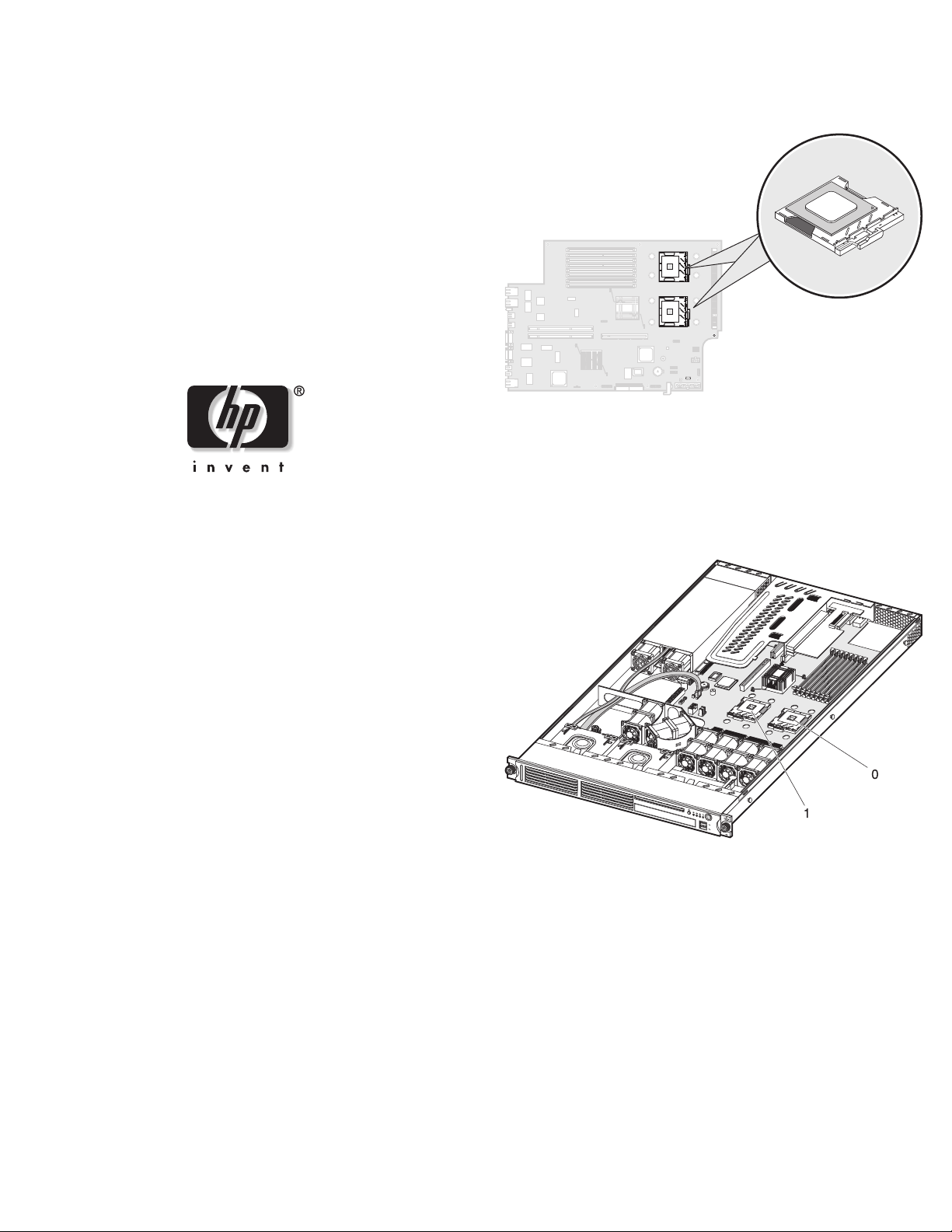
Locating the CPU Socket
The server’s dual mPGA604 (604-pin) sockets support Intel Xeon
800 MHz FSB processors. The location of the two CPU sockets
(U6 and U18) is shown in the figure below.
Installation Guidelines
When installing a processor, observe the following important
guidelines:
• Processor socket 0 (U6) must always be populated. If no
processor is installed in this socket, the system will fail to boot
and halt during POST. This error prevents the system from
functioning properly.
Read instructions completely before beginning
installation procedure.
© Copyright 2005 Hewlett-Packard Development Company, L.P.
The information contained herein is subject to change without notice. The only
warranties for HP products and services are set forth in the express warranty
statements accompanying such products and services. Nothing herein should be
construed as constituting an additional warranty. HP shall not be liable for technical
or editorial errors or omissions contained herein.
Intel and Xeon are trademarks or registered trademarks of Intel Corporation or its
subsidiaries in the United States and other countries.
Intel Processor Installation Instructions
First Edition (March 2005)
Part Number 381735-001
• Handle the processor and heat sink with care. Damage to either
may affect processor performance.
• The pins beneath the processor are very fragile. Do not bend or
damage them.
• Always use a new heat sink when replacing processors. Failure
to use new components can cause damage to the processor.
• Be sure that the server has the most recent ROM version.
Failure to flash the ROM before installing processors can cause
system failure.
Configuring the Processor
NOTE: The procedures described in this document assume that the server
is out of the rack and is positioned on a flat, stable surface.
IMPORTANT: Observe the pre- and post-installation procedures described
in later sections when configuring the processor.
CAUTION: Follow the ESD precautions listed in Chapter 2 of the
HP ProLiant DL140 Generation 2 Server Maintenance and Service
Guide when handling the processor and heat sink. You can
download a copy of this guide from the HP website at
Pre-installation Procedures
Perform the instructions below before removing or installing
a processor.
1. Turn off the server and all the peripherals connected to it.
2. Unplug all cables from the power outlets to avoid exposure to
3. Disconnect telecommunication cables to avoid exposure to
4. Remove the top cover.
5. If necessary, remove any accessory boards or cables that
Removing the Processor
1. Perform the pre-installation procedures described in the
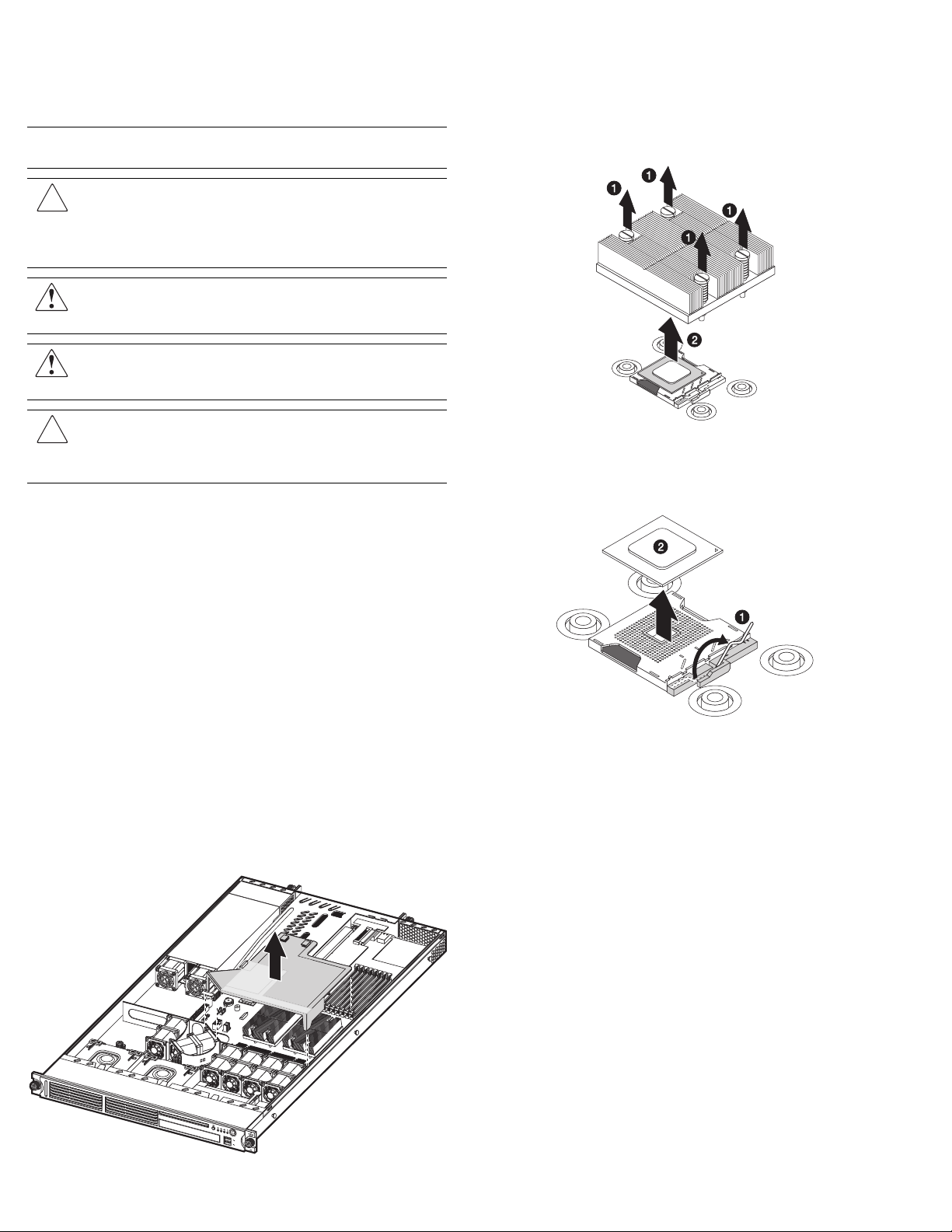
2. Lift the air duct away from the CPU sockets.
http://www.hp.com/.
WARNING: Failure to properly turn off the server before you
open the server may cause serious damage as well as
bodily harm.
WARNING: To reduce the risk of personal injury from hot
surfaces, allow the heat sink and the processor to cool before
touching them.
CAUTION: To prevent the heat sink from tilting to one side during
installation/removal procedures, observe a diagonally opposite
pattern (an “X” pattern) when loosening and tightening the four
spring-loaded screws.
high energy levels that may cause burns when parts are
short-circuited by metal objects such as tools or jewelry.
If necessary, label each one to expedite reassembly.
shock hazard from ringing voltages.
prevent access to the CPU sockets.
previous section.
Keep it for reinstallation later.
3. Locate the processor you want to remove.
4. Remove the heat sink:
a. Loosen the four spring-loaded screws a few threads out,
observing a diagonally opposite pattern, then loosen them
completely to release the heat sink from the processor base.
b. Lift the heat sink away from the system board.
5. Remove the processor:
a. Disengage the socket retention lever from the processor
base.
b. Grasp the processor by its edges and lift it out of its socket.
6. Place the processor on a static-dissipating work surface or
inside an anti-static bag.
Installing the Processor
1. Perform steps 1 and 2 of the “Removing the Processor” section.
2. Locate an empty processor socket.
3. Disengage the socket retention lever from the processor base.
4. Install the processor:
a. Hold the processor by its edges and align it over the empty
CPU socket.
Make sure that pin 1 of the processor (indicated by the gold
triangle on the corner) is properly aligned with hole 1 of the
socket (indicated by a notch). The pins are keyed in such a
way that you cannot install the processor in the wrong
orientation without bending the pins.
b. Insert the processor into the socket.
c. Engage the socket retention lever back into place.

IMPORTANT: If the heat sink is removed for any reason, it is critical that
more thermal interface material be applied to the processor's integrated
heat spreader in order to ensure proper thermal bonding between the
processor and the heat sink. Clean the contact surface of both the
processor and heat sink with an alcohol pad, and re-apply a thin layer of an
HP approved thermal interface material before re-installing the processor.
HP recommends using ShinEtsu G751 thermal grease compound for your
ProLiant server.
7. Reinstall the air duct over the CPU sockets.
A heat sink must be installed for the processor to function
properly. The heat sink model for your ProLiant server already has
a thermal interface material pre-applied on the bottom protected by
a plastic cover. Make sure that this material has no scratches or
gaps. If it does have any scratches or gaps, contact your
HP Customer Support provider for replacement.
CAUTION: To prevent overheating or a possible system crash, use
only a heat sink model specified for this ProLiant model.
5. Remove and discard the plastic cover protecting the thermal
interface material.
Be careful not to touch or scratch the thermal interface
material.
6. Install the heat sink:
a. Align then insert the heat sink on top of the processor.
CAUTION: Do not over tighten the heat sink’s spring-loaded
screws to prevent them from breaking off. A maximum torque of
6 in-lb is set for the system.
b. Tighten the four spring-loaded screws a few threads in,
observing a diagonally opposite pattern, then tighten them
completely to secure the heat sink to the processor base.
8. Perform the post- installation procedures described in the next
section.
Post-installation Procedures
Perform the instructions below after removing or installing a
processor.
1. Be sure all components are installed according to the described
step-by-step instructions.
2. Check to make sure you have not left loose tools or parts inside
the server.
3. Reinstall any expansion board(s), peripheral(s), board cover(s),
and system cable(s) that have previously been removed.
4. Reinstall the top cover.
5. Connect all external cables and the AC power cord to the
system.
6. Press the power button
server.
on the front panel to turn on the
 Loading...