

HP ProLiant DL120 G6 User Manual

HP ProLiant DL100 Series Server
User Guide
for HP ProLiant DL120 G6 Servers
Part Number 579574-003
March 2010 (Third Edition)

© Copyright 2009, 2010 Hewlett-Packard Development Company, L.P.
The information contained herein is subject to change without notice. The only warranties for HP products and services are set forth in the express
warranty statements accompanying such products and services. Nothing herein should be construed as constituting an additional warranty. HP
shall not be liable for technical or editorial errors or omissions contained herein.
Microsoft, Windows, Windows Server, and Windows NT are U.S. registered trademarks of Microsoft Corporation.
Intended audience
This document is for the person who installs, administers, and troubleshoots servers and storage systems.
HP assumes you are qualified in the servicing of computer equipment and trained in recognizing hazards
in products with hazardous energy levels.

Contents
Component identification ............................................................................................................... 6
Front panel components ................................................................................................................................ 6
Front panel LEDs and buttons ......................................................................................................................... 6
SAS and SATA device numbers ..................................................................................................................... 7
Rear panel components ................................................................................................................................ 8
Rear panel LEDs and buttons ......................................................................................................................... 8
PCI expansion slot definitions ........................................................................................................................ 9
System board components ............................................................................................................................ 9
System maintenance switch ............................................................................................................... 10
NMI functionality ............................................................................................................................. 11
System board LEDs ..................................................................................................................................... 11
Fan locations ............................................................................................................................................. 12
Battery pack LEDs ....................................................................................................................................... 12
FBWC module LEDs .................................................................................................................................... 14
Operations................................................................................................................................. 15
Power up the server .................................................................................................................................... 15
Power down the server ............................................................................................................................... 15
Remove the server from the rack .................................................................................................................. 15
Remove the access panel ............................................................................................................................ 16
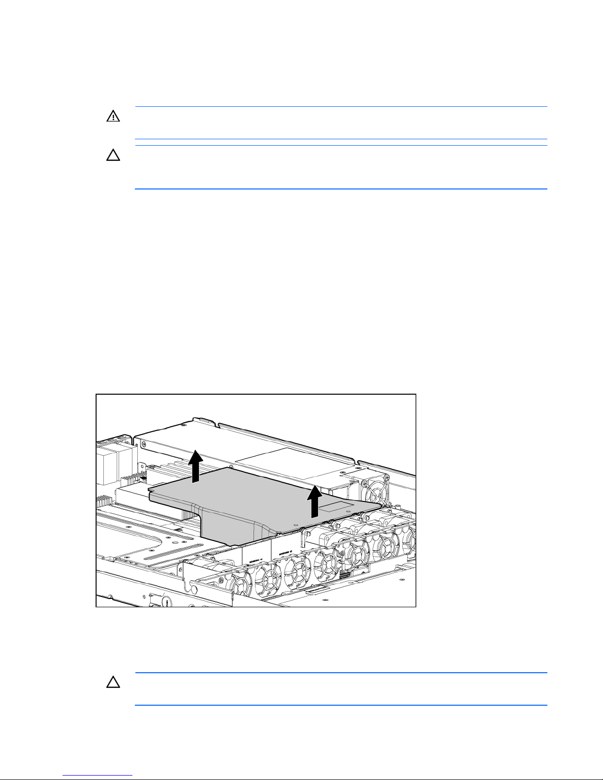
Remove the air baffle .................................................................................................................................. 16
Remove the PCI riser board assembly ........................................................................................................... 16
Install the PCI riser board assembly .............................................................................................................. 17
Setup ......................................................................................................................................... 19
Optional installation services ....................................................................................................................... 19
Rack planning resources ............................................................................................................................. 19
Optimum environment................................................................................................................................. 19
Space and airflow requirements ........................................................................................................ 20
Temperature requirements ................................................................................................................. 20
Power requirements .......................................................................................................................... 21
Electrical grounding requirements ...................................................................................................... 21
Rack warnings ........................................................................................................................................... 22
Installing hardware options ......................................................................................................................... 22
Powering up and configuring the server ........................................................................................................ 22
Installing the operating system ..................................................................................................................... 22
Registering the server.................................................................................................................................. 22
Hardware options installation ....................................................................................................... 23
Introduction ............................................................................................................................................... 23
Memory options ......................................................................................................................................... 23
Memory subsystem architecture ......................................................................................................... 23
Single-, dual-, and quad-rank DIMMs ................................................................................................. 24
DIMM identification .......................................................................................................................... 24
General DIMM slot population guidelines ........................................................................................... 25
Installing DIMMs ................................
Hard drive options ..................................................................................................................................... 26
.............................................................................................. 26

Hard drive guidelines ....................................................................................................................... 27
Removing a hard drive blank ............................................................................................................ 27
Removing a hard drive ..................................................................................................................... 27
Installing a hot-plug hard drive .......................................................................................................... 28
Installing a non-hot-plug hard drive .................................................................................................... 29
Optical drive option ................................................................................................................................... 33
Expansion board option .............................................................................................................................. 34
PCI-X riser board option .............................................................................................................................. 35
Storage controller option ............................................................................................................................. 37
SAS hard drive LED cable option ................................................................................................................. 37
Battery-backed write cache battery pack option ............................................................................................. 38
Installing the FBWC module and capacitor pack ........................................................................................... 40
HP Trusted Platform Module option .............................................................................................................. 42
Installing the Trusted Platform Module board ....................................................................................... 42
Retaining the recovery key/password ................................................................................................. 44
Enabling the Trusted Platform Module ................................................................................................. 44
Cabling ..................................................................................................................................... 45
Cabling overview ....................................................................................................................................... 45
Server cabling ........................................................................................................................................... 45
BBWC battery cabling to an optional controller............................................................................................. 46
Power supply (500 W) cabling .................................................................................................................... 46
SATA cabling ............................................................................................................................................ 47
SATA cabling to the SGPIO connector and the 12C cable connector............................................................... 47
SAS cabling to the SGPIO connector and the 12C cable connector................................................................. 48
Internal USB cabling ................................................................................................................................... 48
Fan cabling ............................................................................................................................................... 49
Software and configuration utilities ............................................................................................... 50
BIOS Setup Utility ....................................................................................................................................... 50
Auto-configuration process .......................................................................................................................... 50
BIOS Serial Console ................................................................................................................................... 51
ROMPaq utility ........................................................................................................................................... 51
LO100i Remote Management ...................................................................................................................... 51
HP Insight Diagnostics ................................................................................................................................ 51
HP ROM-Based Setup Utility ........................................................................................................................ 52
Re-entering the server serial number and product ID ....................................................................................... 52
Keeping the system current .......................................................................................................................... 53
Drivers ............................................................................................................................................ 53
Firmware ......................................................................................................................................... 53
Subscriber's choice .......................................................................................................................... 53
Troubleshooting .......................................................................................................................... 54
Common problem resolution ........................................................................................................................ 54
Loose connections ............................................................................................................................ 54
Service notifications
Firmware updates ............................................................................................................................ 54
DIMM handling guidelines ................................................................................................................ 55
SAS and SATA hard drive guidelines ................................................................................................. 55
Problem diagnosis ...................................................................................................................................... 55
Important safety information .............................................................................................................. 56
Preparing the server for diagnosis ...................................................................................................... 58
Symptom information ........................................................................................................................ 58
Diagnostic steps ............................................................................................................................... 58
.......................................................................................................................... 54

Hardware problems ................................................................................................................................... 68
Power problems ............................................................................................................................... 68
Unknown problem ............................................................................................................................ 70
General hardware problems ............................................................................................................. 71
Internal system problems ................................................................................................................... 72
System open circuits and short circuits ................................................................................................ 79
External device problems .................................................................................................................. 80
Software tools and solutions ........................................................................................................................ 85
Introduction to software problems ...................................................................................................... 85
Firmware maintenance ..................................................................................................................... 88
Contacting HP ........................................................................................................................................... 90
Contacting HP technical support or an authorized reseller .................................................................... 90
Server information you need .............................................................................................................. 90
Operating system information you need ............................................................................................. 91
Battery ....................................................................................................................................... 93
Regulatory compliance notices ..................................................................................................... 94
Regulatory compliance identification numbers ............................................................................................... 94
Federal Communications Commission notice ................................................................................................. 94
FCC rating label .............................................................................................................................. 94
Class A equipment ........................................................................................................................... 94
Class B equipment ............................................................................................................................ 94
Declaration of conformity for products marked with the FCC logo, United States only ........................................ 95
Modifications ............................................................................................................................................. 95
Cables ...................................................................................................................................................... 95
Canadian notice (Avis Canadien) ................................................................................................................ 96
European Union regulatory notice ................................................................................................................ 96
Disposal of waste equipment by users in private households in the European Union .......................................... 96
Japanese notice ......................................................................................................................................... 97
BSMI notice ............................................................................................................................................... 97
Korean notice ............................................................................................................................................ 98
Laser compliance ....................................................................................................................................... 98
Battery replacement notice .......................................................................................................................... 98
Taiwan battery recycling notice ................................................................................................................... 99
Power cord statement for Japan ................................................................................................................... 99
Acoustics statement for Germany (Geräuschemission) .................................................................................... 99
Electrostatic discharge ............................................................................................................... 100
Preventing electrostatic discharge .............................................................................................................. 100
Grounding methods to prevent electrostatic discharge .................................................................................. 100
Technical support ...................................................................................................................... 101
HP contact information .............................................................................................................................. 101
Before you contact HP .............................................................................................................................. 101
Customer Self Repair ................................................................................................................................ 101
Acronyms and abbreviations ...................................................................................................... 109
Index ................................................................................................
....................................... 113
Component identification
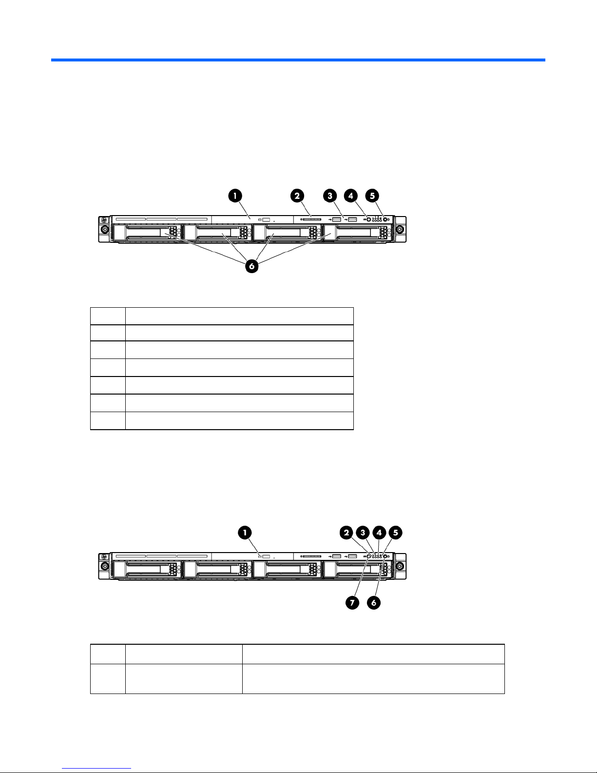
Front panel components
Item Description
1 Optical drive
2 Serial label pull tab
3 USB ports (2)
4 Unit Identification (UID) button/LED
5 Power/standby button LED
6 Hard drive bays (4)
Front panel LEDs and buttons
Item Description Status
1 Optical drive LED On = Drive is in use.
Off = Drive is not active.
Component identification 6
Item Description Status
2 Internal health LED Green = System health is normal.
Amber = System health is degraded. To identify the component in
a degraded state, see "System board LEDs (on page 11)."
Red = System health is critical. To identify the component in a
critical state, see "System board LEDs (on page 11)."
Off = System health is normal (when in standby mode).
3 NIC 1 link/activity LED Green = Network link exists.
Flashing green = Network link and activity exist.
Off = No network link exists.
If power is off, view the LEDs on the RJ-45 connector. See "Rear
panel LEDs and buttons (on page 8)."
4 NIC 2 link/activity LED Green = Network link exists.
Flashing green = Network link and activity exist.
Off = No network link exists.
If power is off, view the LEDs on the RJ-45 connector. See "Rear
panel LEDs and buttons (on page 8)."
5 Drive activity LED Green = Drive activity is normal.
Off = No drive activity exists.
6
Power On/Standby button
and system power LED
7 UID button/LED Blue = Identification is activated.
Green = Normal (system on)
Amber = System is in standby, but power is still applied.
Off = Power cord is not attached or the power supply has failed.
Flashing blue = System is being managed remotely.
Off = Identification is deactivated.
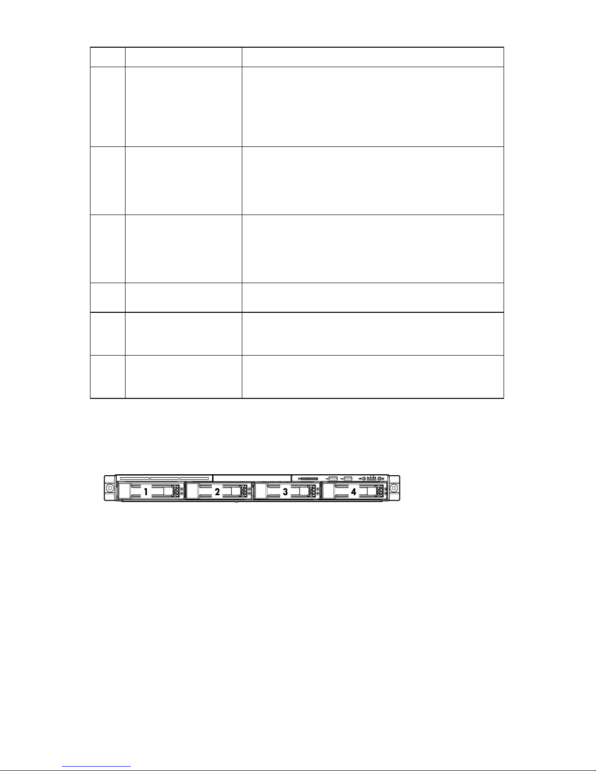
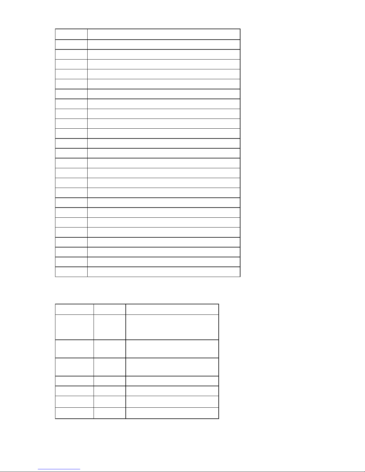
SAS and SATA device numbers
Component identification 7
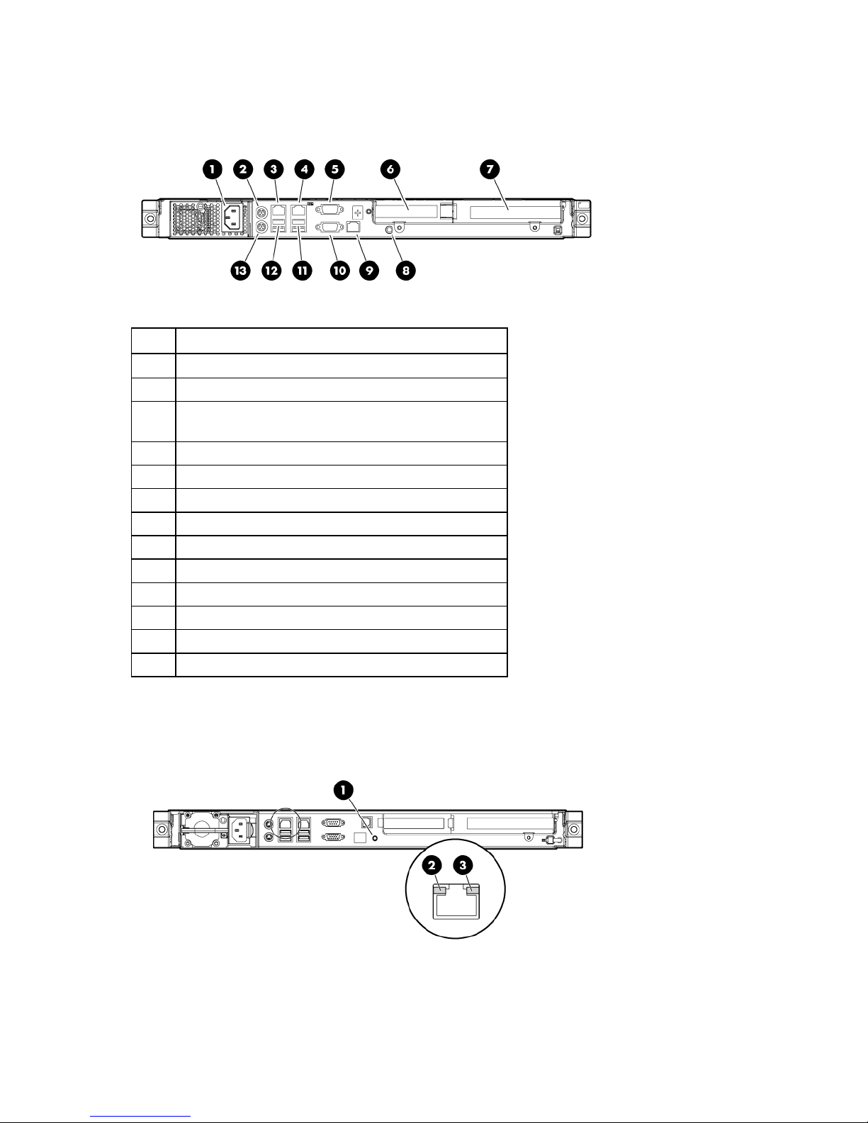
Rear panel components
Item Description
1 Power cord connector
2 Mouse connector
3
4 10/100/1000 NIC 2 connector
5 Serial connector
6 Slot 1 PCIe2 x16 (4, 2, 1)
7 Slot 2 PCIe2 x16 (16, 8, 4, 1)
8 UID button/LED
9 Dedicated Lights-Out 100 management port
10 Video connector
11 USB connectors (2)
12 USB connectors (2)
13 Keyboard connector
10/100/1000 NIC 1 connector/shared Lights-Out 100
management port
Rear panel LEDs and buttons
Component identification 8
Item Description Status
1 UID button/LED Blue = Identification
Flashing blue = System is being managed
remotely.
Off = Off
2
3
NIC/Lights-Out
100 link
NIC/Lights-Out
100 activity
Green or flashing green = 10M/100M link
speed
Amber = 1-GB link speed
Off = No connection
Green = Linked to the network
Flashing green = Linked and activity on the
network
Off = No network activity
PCI expansion slot definitions
Slot Type Length Connector Interconnect
1 PCIe2 Full x16 x16
1 Optional PCI-X Full 133 MHz/3.3 V 64 bit
2 PCIe Half x16 x4
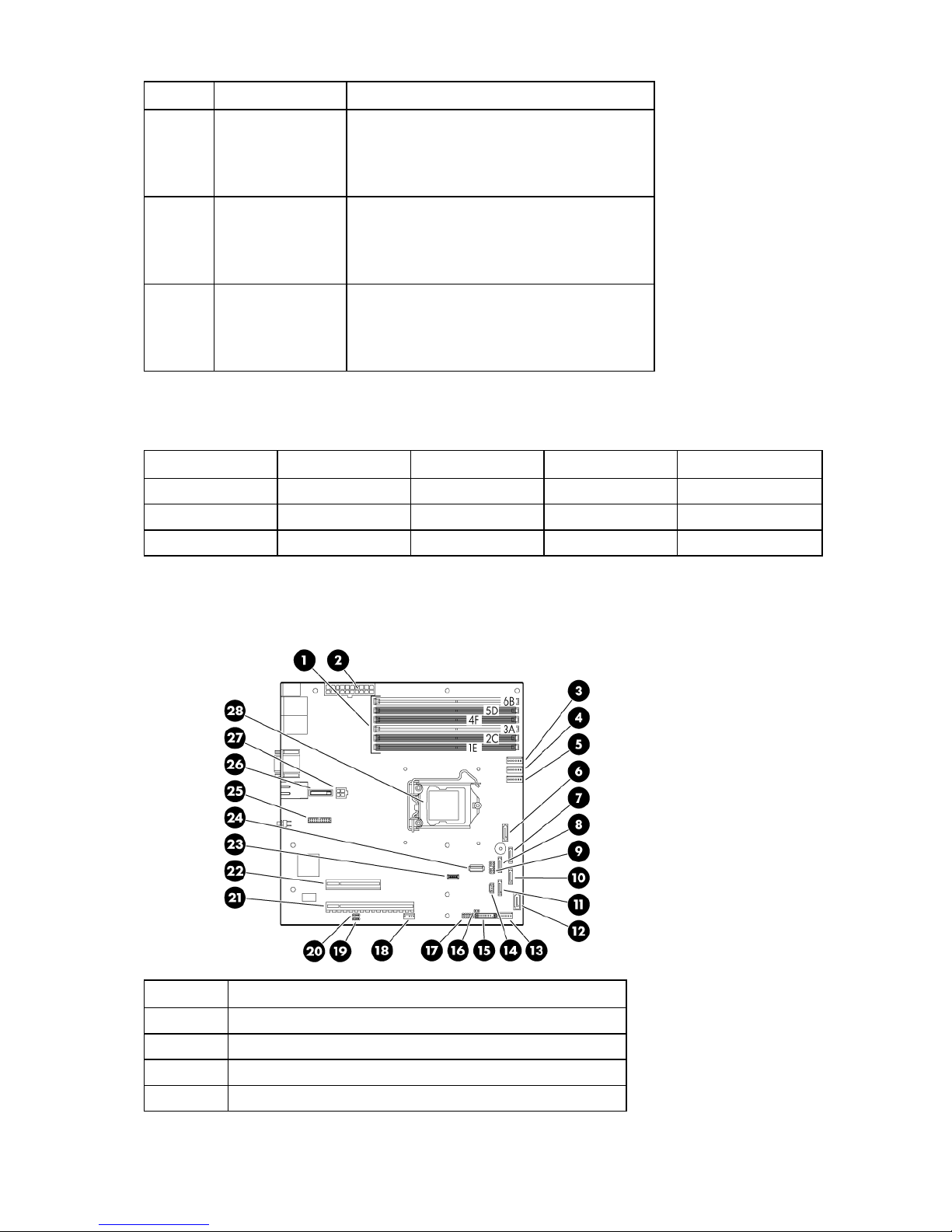
System board components
Item Description
1 DIMM slots (6)
2 24-pin ATX system board power connector
3 Processor fan 1 cable connector
4 Processor fan 2 cable connector
Component identification 9
Item Description
5 Processor fan 3 cable connector
6 Optical drive SATA cable connector
7 Hard drive 4 SATA cable connector
8 Hard drive 3 SATA cable connector
9 Hard drive backplane SGPIO connector
10 Hard drive 2 SATA cable connector
11 Hard drive 1 SATA cable connector
12 Reserved
13 System fan 4 cable connector
14 Hard drive backplane 12C cable connector
15 Front panel board cable connector
16 External SAS hard drive LED cable connector
17 Front USB port cable connector
18 Internal USB connector for tape device
19 BMC recovery jumper
20 BMC password reset jumper
21 Expansion slot 1 (for riser board)
22 Expansion slot 2 (for riser board)
23 System maintenance switch
24 Internal USB connector for STD USB
25 TPM connector
26 System battery
27 4-pin ATX processor power connector
28 Processor
System maintenance switch
Position Default Function
S1 Off Off = Normal
S2 Off Off = Normal BIOS boot block
S3 Off Off = Disables the RAID key.
S4 Off Reserved
S5 Off Reserved
S6 Off Reserved
S7 Off Reserved
On = Clears the BIOS CMOS and
rests the administrator password.
On = Recovery BIOS boot block
On = Enables the RAID key.
Component identification 10

Position Default Function
S8 Off Reserved
NMI functionality
An NMI crash dump enables administrators to create crash dump files when a system is hung and is not
responding to traditional debug mechanisms.
Crash dump log analysis is an essential part of diagnosing reliability problems, such as hangs in
operating systems, device drivers, and applications. Many crashes freeze a system, and the only
available action for administrators is to cycle the system power. Resetting the system erases any
information that could support problem analysis, but the NMI feature preserves that information by
performing a memory dump before a hard reset.
To force the OS to invoke the NMI handler and generate a crash dump log, the administrator can do any
of the following:
• Short the NMI jumper pins
• Press the NMI switch
• Use the Lights-Out 100 Virtual NMI feature
For additional information, see the whitepaper on the HP website
(http://h20000.www2.hp.com/bc/docs/support/SupportManual/c00797875/c00797875.pdf
System board LEDs
Item LED description Status
).
1 Processor fan failure Amber = Processor fan error
2 DIMM failure Amber = DIMM has failed or is missing.
Off = Normal
Off = Normal
Component identification 11
Item LED description Status
3 Overtemperature
4 System fan failure Amber = System fan has failed or is missing.
5 BMC Heartbeat Flashing = Normal
Fan locations
Amber = System has reached a cautionary or
critical temperature level.
Off = Normal
Off = Normal
Off = BMC is not functioning.
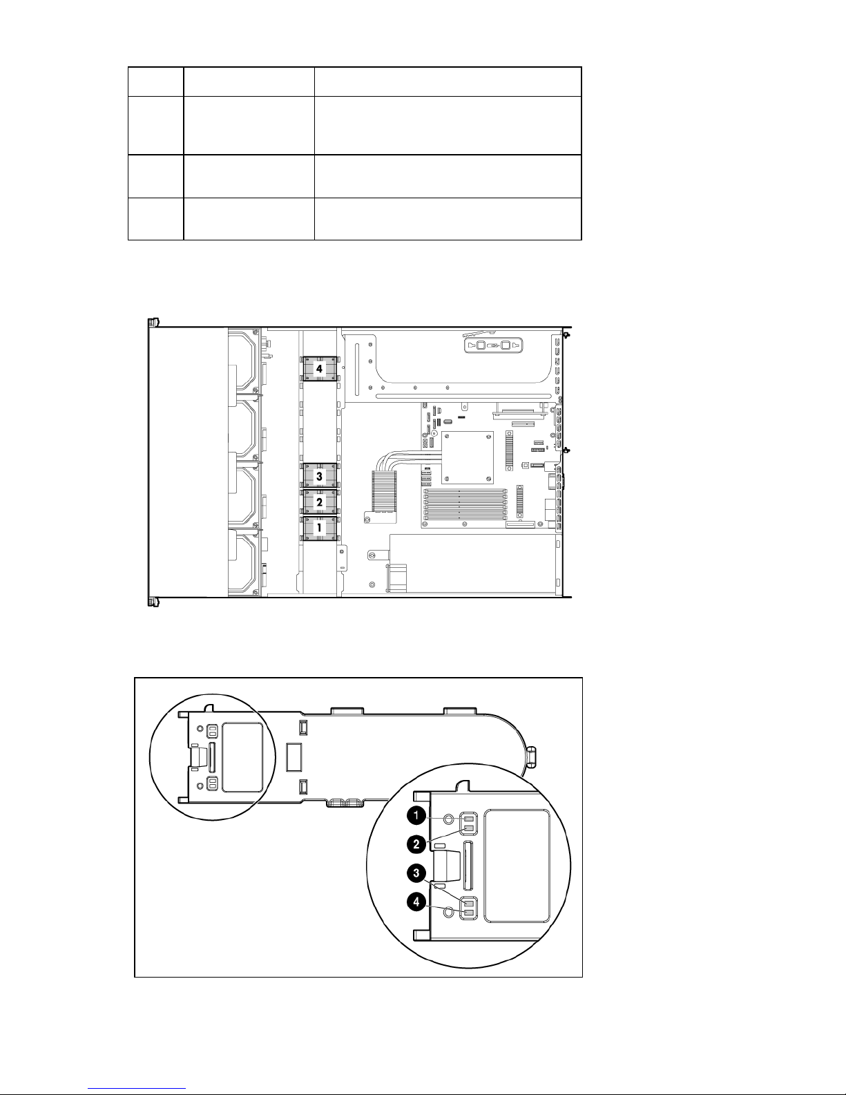
Battery pack LEDs
Component identification 12
Item ID Color Description
1 Green
2 Green
3 Amber
System Power LED. This LED glows steadily when the
system is powered up and 12 V system power is
available. This power supply is used to maintain the
battery charge and provide supplementary power to the
cache microcontroller.
Auxiliary Power LED. This LED glows steadily when 3.3V
auxiliary voltage is detected. The auxiliary voltage is
used to preserve BBWC data and is available any time
that the system power cords are connected to a power
supply.
Battery Health LED. To interpret the illumination patterns
of this LED, see the following table.
4 Green
BBWC Status LED. To interpret the illumination patterns
of this LED, see the following table.
LED3 pattern LED4 pattern Interpretation
—
—
—
— Steady glow
— Off
One blink per
second
Steady glow —
One blink per
second
One blink every
two seconds
Double blink,
then pause
One blink per
second
One blink per
second
—
The system is powered down, and the cache contains data that has
not yet been written to the drives. Restore system power as soon as
possible to prevent data loss.
Data preservation time is extended any time that 3.3 V auxiliary
power is available, as indicated by LED 2. In the absence of
auxiliary power, battery power alone preserves the data. A fullycharged battery can normally preserve data for at least two days.
The battery lifetime also depends on the cache module size. For
further information, refer to the controller QuickSpecs on the HP
website (http://www.hp.com
The cache microcontroller is waiting for the host controller to
communicate.
The battery pack is below the minimum charge level and is being
charged. Features that require a battery (such as write cache,
capacity expansion, stripe size migration, and RAID migration) are
temporarily unavailable until charging is complete. The recharge
process takes between 15 minutes and two hours, depending on
the initial capacity of the battery.
The battery pack is fully charged, and posted write data is stored
in the cache.
The battery pack is fully charged, and there is no posted write data
in the cache.
An alternating green and amber blink pattern indicates that the
cache microcontroller is executing from within its boot loader and
receiving new flash code from the host controller.
There is a short circuit across the battery terminals or within the
battery pack. BBWC features are disabled until the battery pack is
replaced. The life expectancy of a battery pack is typically more
than three years.
There is an open circuit across the battery terminals or within the
battery pack. BBWC features are disabled until the battery pack is
replaced. The life expectancy of a battery pack is typically more
than three years.
).
Component identification 13
•
•
FBWC module LEDs
The FBWC module has two single-color LEDs (green and amber). The LEDs are duplicated on the reverse
side of the cache module to facilitate status viewing.
Green LED Amber LED Interpretation
Off On A backup is in progress.
Flashing (1 Hz) On A restore is in progress.
Flashing (1 Hz) Off The capacitor pack is charging.
On Off The capacitor pack has completed charging.
Flashing (2 Hz)
Alternating with
amber LED
Flashing (2 Hz)
Alternating with
green LED
One of the following conditions exists:
The charging process has timed out.
The capacitor pack is not connected.
On On The flash code image failed to load.
Off Off The flash code is corrupt.
Component identification 14

Operations
Power up the server
To power up the server, press the Power On/Standby button.
Power down the server
WARNING: To reduce the risk of personal injury, electric shock, or damage to the
equipment, remove the power cord to remove power from the server. The front panel Power
On/Standby button does not completely shut off system power. Portions of the power supply
1. Back up the server data.
2. Shut down the operating system as directed by the operating system documentation.
3. Press the Power On/Standby button to place the server in Standby mode. When the server activates
4. Disconnect the power cords.
and some internal circuitry remain active until AC power is removed.
IMPORTANT: If installing a hot-plug device, it is not necessary to power down the server.
NOTE: If the operating system automatically places the server in Standby mode, omit the next
step.
Standby power mode, the system power LED changes to amber.
IMPORTANT: Pressing the UID button illuminates the blue UID LEDs on the front and rear
panels. In a rack environment, this feature facilitates locating a server when moving between
the front and rear of the rack.
The system is now without power.
Remove the server from the rack
WARNING: The server is not attached to the rack mounting rails. To avoid potential damage
to the server and personal injury, always support the server with both hands when removing it
To remove the server from an HP, Compaq branded, telco, or third-party rack:
1. Power down the server (on page 15).
2. Disconnect all peripheral cables and power cords from the server rear panel.
3. Loosen the thumbscrews that secure the server faceplate to the front of the rack.
4. Remove the server from the rack. For more information, see the documentation that ships with the
from the rack.
rack mounting option.
Operations 15
5.
Place the server on a sturdy, level surface.
Remove the access panel
WARNING: To reduce the risk of personal injury from hot surfaces, allow the drives and the
internal system components to cool before touching them.
CAUTION: Do not operate the server for long periods with the access panel open or
removed. Operating the server in this manner results in improper airflow and improper
cooling that can lead to thermal damage.
To remove the component:
1. Power down the server (on page 15).
2. Remove the server from the rack (on page 15).
3. Open the latch, slide the access panel to the rear of the chassis, and remove the access panel.
If the latch is locked, use a T-15 Torx screwdriver to unlock the latch.
Remove the air baffle
To remove the component:
1. Power down the server (on page 15).
2. Remove the server from the rack (on page 15).
3. Remove the access panel (on page 16).
To replace the component, reverse the removal procedure.
Remove the PCI riser board assembly
CAUTION: To prevent damage to the server or expansion boards, power down the server
and remove all AC power cords before removing or installing the PCI riser board assembly.
Operations 16
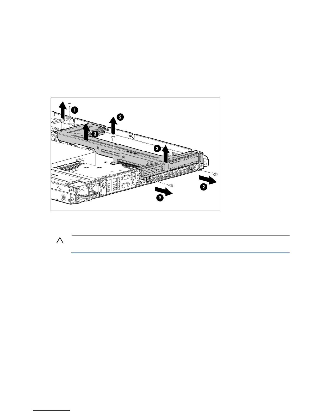
1.
Power down the server (on page 15).
2. Remove the server from the rack (on page 15).
3. Remove the access panel (on page 16).
4. Disconnect all internal cables connected to existing expansion boards.
5. Remove the PCI riser board assembly:
a. Remove the T-10 screw.
b. Remove the T-15 screws.
c. Remove the riser board assembly.
Install the PCI riser board assembly
CAUTION: To prevent damage to the server or expansion boards, power down the server
and remove all AC power cords before removing or installing the PCI riser board assembly.
Operations 17
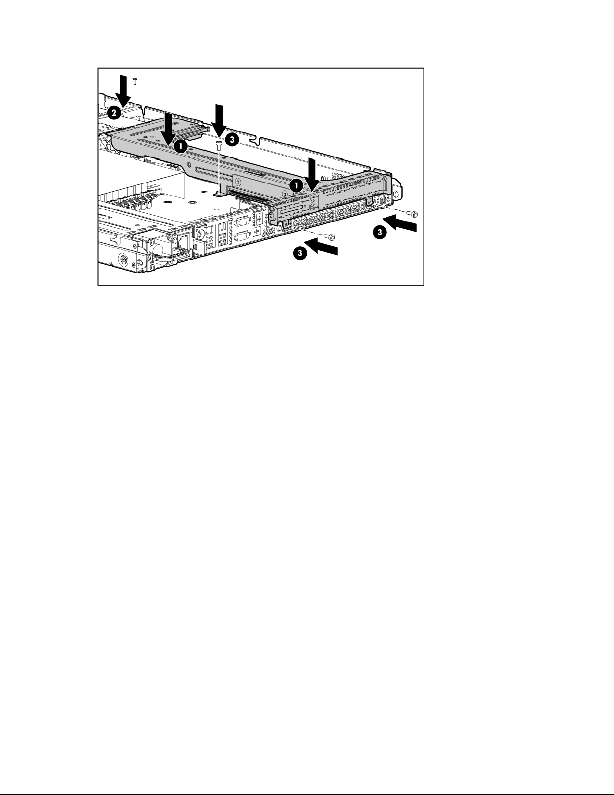
1.
Install the PCI riser board assembly.
2. Connect any internal cables for expansion boards.
3. Install the access panel.
4. Install the server into the rack.
Operations 18

Setup
Optional installation services
Delivered by experienced, certified engineers, HP Care Pack services help you keep your servers up and
running with support packages tailored specifically for HP ProLiant systems. HP Care Packs let you
integrate both hardware and software support into a single package. A number of service level options
are available to meet your needs.
HP Care Pack Services offer upgraded service levels to expand the standard product warranty with easyto-buy, easy-to-use support packages that help you make the most of your server investments. Some of the
Care Pack services are:
• Hardware support
o 6-hour call-to-repair
o 4-hour 24x7 same day
o 4-hour same business day
• Software support
o Microsoft®
o Linux
• Integrated hardware and software support
o Critical Service
o Proactive 24
o Support Plus
o Support Plus 24
• Startup and implementation services for both hardware and software
For more information on Care Packs, refer to the HP website
(http://www.hp.com/hps/carepack/servers/cp_proliant.html
Rack planning resources
The rack resource kit ships with all HP branded or Compaq branded 9000, 10000, and H9 series racks.
For more information on the content of each resource, refer to the rack resource kit documentation.
If you intend to deploy and configure multiple servers in a single rack, refer to the white paper on highdensity deployment at the HP website (http://www.hp.com/products/servers/platforms
).
).
Optimum environment
When installing the server, select a location that meets the environmental standards described in this
section.
Setup 19

Space and airflow requirements
Tower server
In a tower configuration, leave at least a 7.6-cm (3-in) clearance space at the front and back of the server
for proper ventilation.
Rack server
To allow for servicing and adequate airflow, observe the following space and airflow requirements when
deciding where to install a rack:
• Leave a minimum clearance of 63.5 cm (25 in) in front of the rack.
• Leave a minimum clearance of 76.2 cm (30 in) behind the rack.
• Leave a minimum clearance of 121.9 cm (48 in) from the back of the rack to the back of another
rack or row of racks.
HP servers draw in cool air through the front door and expel warm air through the rear door. Therefore,
the front and rear rack doors must be adequately ventilated to allow ambient room air to enter the
cabinet, and the rear door must be adequately ventilated to allow the warm air to escape from the
cabinet.
CAUTION: To prevent improper cooling and damage to the equipment, do not block the
When vertical space in the rack is not filled by a server or rack component, the gaps between the
components cause changes in airflow through the rack and across the servers. Cover all gaps with
blanking panels to maintain proper airflow.
The 9000 and 10000 Series Racks provide proper server cooling from flow-through perforations in the
front and rear doors that provide 64 percent open area for ventilation.
ventilation openings.
CAUTION: Always use blanking panels to fill empty vertical spaces in the rack. This
arrangement ensures proper airflow. Using a rack without blanking panels results in improper
cooling that can lead to thermal damage.
CAUTION: When using a Compaq branded 7000 Series rack, you must install the high
airflow rack door insert [P/N 327281-B21 (42U) or P/N 157847-B21 (22U)] to provide
proper front-to-back airflow and cooling.
CAUTION: If a third-party rack is used, observe the following additional requirements to
ensure adequate airflow and to prevent damage to the equipment:
• Front and rear doors—If the 42U rack includes closing front and rear doors, you must
allow 5,350 sq cm (830 sq in) of holes evenly distributed from top to bottom to permit
adequate airflow (equivalent to the required 64 percent open area for ventilation).
• Side—The clearance between the installed rack component and the side panels of the rack
must be a minimum of 7 cm (2.75 in).
Temperature requirements
To ensure continued safe and reliable equipment operation, install or position the system in a wellventilated, climate-controlled environment.
Setup 20

The maximum recommended ambient operating temperature (TMRA) for most server products is 35°C
(95°F). The temperature in the room where the rack is located must not exceed 35°C (95°F).
CAUTION: To reduce the risk of damage to the equipment when installing third-party options:
• Do not permit optional equipment to impede airflow around the server or to increase the
internal rack temperature beyond the maximum allowable limits.
• Do not exceed the manufacturer’s TMRA.
Power requirements
Installation of this equipment must comply with local and regional electrical regulations governing the
installation of information technology equipment by licensed electricians. This equipment is designed to
operate in installations covered by NFPA 70, 1999 Edition (National Electric Code) and NFPA-75, 1992
(code for Protection of Electronic Computer/Data Processing Equipment). For electrical power ratings on
options, refer to the product rating label or the user documentation supplied with that option.
WARNING: To reduce the risk of personal injury, fire, or damage to the equipment, do not
overload the AC supply branch circuit that provides power to the rack. Consult the electrical
When installing more than one server, you may need to use additional power distribution devices to
safely provide power to all devices. Observe the following guidelines:
authority having jurisdiction over wiring and installation requirements of your facility.
CAUTION: Protect the server from power fluctuations and temporary interruptions with a
regulating uninterruptible power supply (UPS). This device protects the hardware from
damage caused by power surges and voltage spikes and keeps the system in operation
during a power failure.
• Balance the server power load between available AC supply branch circuits.
• Do not allow the overall system AC current load to exceed 80 percent of the branch circuit AC
current rating.
• Do not use common power outlet strips for this equipment.
• Provide a separate electrical circuit for the server.
Electrical grounding requirements
The server must be grounded properly for proper operation and safety. In the United States, you must
install the equipment in accordance with NFPA 70, 1999 Edition (National Electric Code), Article 250,
as well as any local and regional building codes. In Canada, you must install the equipment in
accordance with Canadian Standards Association, CSA C22.1, Canadian Electrical Code. In all other
countries, you must install the equipment in accordance with any regional or national electrical wiring
codes, such as the International Electrotechnical Commission (IEC) Code 364, parts 1 through 7.
Furthermore, you must be sure that all power distribution devices used in the installation, such as branch
wiring and receptacles, are listed or certified grounding-type devices.
Because of the high ground-leakage currents associated with multiple servers connected to the same
power source, HP recommends the use of a PDU that is either permanently wired to the building’s branch
circuit or includes a nondetachable cord that is wired to an industrial-style plug. NEMA locking-style plugs
or those complying with IEC 60309 are considered suitable for this purpose. Using common power outlet
strips for the server is not recommended.
Setup 21

Rack warnings
WARNING: To reduce the risk of personal injury or damage to the equipment, be sure that:
• The leveling jacks are extended to the floor.
• The full weight of the rack rests on the leveling jacks.
• The stabilizing feet are attached to the rack if it is a single-rack installation.
• The racks are coupled together in multiple-rack installations.
• Only one component is extended at a time. A rack may become unstable if more than one
component is extended for any reason.
WARNING: To reduce the risk of personal injury or equipment damage when unloading a
rack:
• At least two people are needed to safely unload the rack from the pallet. An empty 42U
rack can weigh as much as 115 kg (253 lb), can stand more than 2.1 m (7 ft) tall, and
may become unstable when being moved on its casters.
• Never stand in front of the rack when it is rolling down the ramp from the pallet. Always
handle the rack from both sides.
Installing hardware options
Install any hardware options before initializing the server. For options installation information, refer to the
option documentation. For server-specific information, refer to "Hardware options installation (on page
23)."
Powering up and configuring the server
To power up the server, press the Power On/Standby button.
For detailed information on configuring the server, see the server installation sheet.
Installing the operating system
To operate properly, the server must have a supported operating system. For the latest information on
supported operating systems, refer to the HP website (http://www.hp.com/go/supportos
To install an operating system on the server, insert the operating system CD into the CD-ROM drive and
reboot the server. This process may require you to obtain additional drivers from the support CD shipped
with the server or the CD that shipped with the option. The drivers may have updates that are available
on the HP website (http://www.hp.com/support
Follow the on-screen instructions to begin the installation process.
).
Registering the server
To register the server, refer to the HP Registration website (http://register.hp.com).
).
Setup 22
Hardware options installation
Introduction
If more than one option is being installed, read the installation instructions for all the hardware options
and identify similar steps to streamline the installation process.
WARNING: To reduce the risk of personal injury from hot surfaces, allow the drives and the
internal system components to cool before touching them.
CAUTION: To prevent damage to electrical components, properly ground the server before
beginning any installation procedure. Improper grounding can cause electrostatic discharge.
Memory options
IMPORTANT: This server does not support mixing RDIMMs and UDIMMs. Attempting to mix
these two types causes the server to halt during BIOS initialization.
The memory subsystem in this server can support RDIMMs or UDIMMs. Both types are referred to as
DIMMs when the information applies to both types. When specified as RDIMM or UDIMM, the
information applies to that type only. All memory installed in the server must be the same type.
The server supports the following DIMM speeds:
• Single- and dual-rank PC3-10600 (DDR-1333) DIMMs operating at 1333 and 1066 MHz
• Quad-rank PC3-8500 (DDR-1067) DIMMs operating at 1066 MHz
Depending on the processor model, the number of DIMMs installed, and whether UDIMMs or RDIMMs
are installed, the memory clock speed may be reduced to 1066 or 800 MHz. For more information on
Memory subsystem architecture
the effect of DIMM slot population, see "General DIMM slot population guidelines (on page 25)."
The memory subsystem in this server is divided into channels. The processor supports two channels, and
each channel supports three DIMM slots, as shown in the following table.
Channel Slot Slot number
1 E
C
A
2 F
D
B
This server supports both Registered PC3 DIMMs (RDIMMs) and Unbuffered DIMMs (UDIMMs).
1
2
3
4
5
6
Hardware options installation 23
DIMM slots in this server are identified by number and by letter. Letters identify the slots to populate for
specific AMP modes. Slot numbers are reported by ROM messages during boot and for error reporting.
Single-, dual-, and quad-rank DIMMs
To understand and configure memory protection modes properly, an understanding of single-, dual-, and
quad-rank DIMMs is helpful. Some DIMM configuration requirements are based on these classifications.
A single-rank DIMM has one set of memory chips that is accessed while writing to or reading from the
memory. A dual-rank DIMM is similar to having two single-rank DIMMs on the same module, with only
one rank accessible at a time. A quad-rank DIMM is, effectively, two dual-rank DIMMs on the same
module. Only one rank is accessible at a time. The server memory control subsystem selects the proper
rank within the DIMM when writing to or reading from the DIMM.
Dual- and quad-rank DIMMs provide the greatest capacity with the existing memory technology. For
example, if current DRAM technology supports 2-GB single-rank DIMMs, a dual-rank DIMM would be 4GB, and a quad-rank DIMM would be 8-GB.
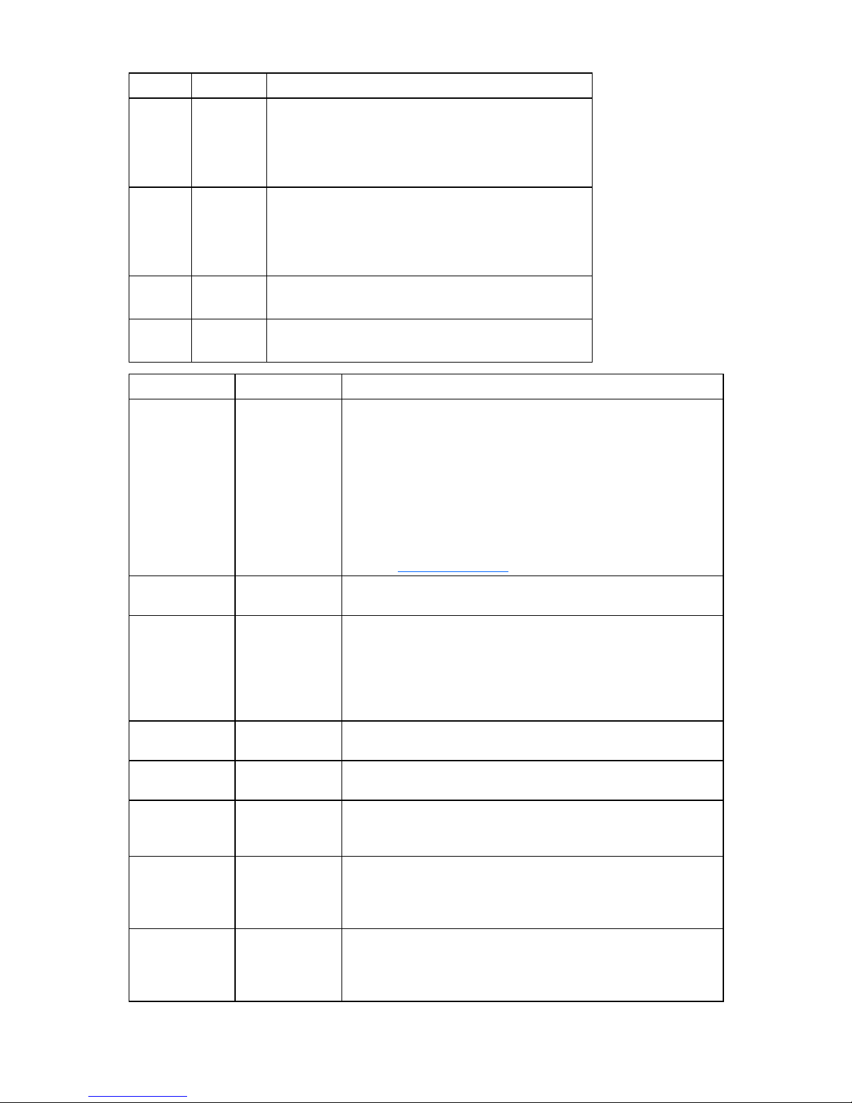
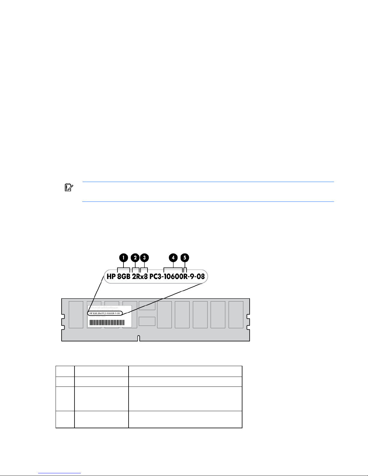
DIMM identification
IMPORTANT: This server does not support mixing RDIMMs and UDIMMs. Attempting to mix
The memory subsystem may be populated with either RDIMMs or UDIMMs, but mixing the two types is not
supported. To determine DIMM characteristics, use the label attached to the DIMM and the following
illustration and table.
these two types causes the server to halt during BIOS initialization.
Item Description Definition
1 Size —
2 Rank
3 Data width
1R = Single-rank
2R = Dual-rank
4R = Quad-rank
x4 = 4-bit
x8 = 8-bit
Hardware options installation 24

Item Description Definition
4 Memory speed
5 DIMM type
For the latest supported memory information, see the QuickSpecs on the HP website
(http://www.hp.com
).
10600 = 1333-MHz
8500 = 1066-MHz
R = RDIMM (registered)
E = UDIMM (unbuffered with ECC)
General DIMM slot population guidelines
• The HP ProLiant DL120 G6 Server has six memory slots.
• There are two channels per server with three DIMM slot per channel.
• Memory channel 1 consists of the three (3) DIMMs that are closest to the processor
• Memory channel 2 consists of the three (3) DIMMs that are furthest from the processor
• Different types of processors have different types of memory support.
• The server supports up to 12 GB (6 x 2-GB) for Registered Memory configurations.
• The server supports up to 16 GB (4 x 4-GB) for Unbuffered Memory configurations.
Observe the following guidelines when installing DIMMs:
• Do not mix Unbuffered and Registered PC3 DIMMs.
• Do not mix DIMMs of varying speeds.
• Do not mix DIMMs of varying voltages.
• Do not mix Unbuffered memory (UDIMMs) with Registered memory (RDIMMs).
• Do not install DIMMs if the processor is not installed.
• Populate DIMMs from heaviest load (double-rank) to lightest load (single-rank) within a channel.
• Heaviest load (DIMM with most ranks) within a channel goes furthest from the CPU.
• Non-ECC DIMMs are not supported
• Each channel supports up to two Unbuffered DIMMs.
• When using UDIMMs, use ECC only.
• When possible, balance the loads per channel.
• If quad-rank DIMMs are installed for the processor, a maximum of two DIMMs can be installed on
each channel for that processor.
• If a channel contains quad-rank DIMMs, the quad-rank DIMM must be installed first on that channel.
• 256MB technology, x4 DRAM on UDIMMs and quad-rank UDIMMs are not supported.
• Always use HP qualified DIMMs.
Populate the DIMM slots in the following sequence:
• DIMM 3A and DIMM 6B
• DIMM 2C and DIMM 5D
• DIMM1E and DIMM 4F
Hardware options installation 25
Installing DIMMs
CAUTION: To avoid damage to the hard drives, memory, and other system components, the
1. Power down the server (on page 15).
2. Do one of the following:
3. Remove the access panel (on page 16).
4. Remove the air baffle (on page 16).
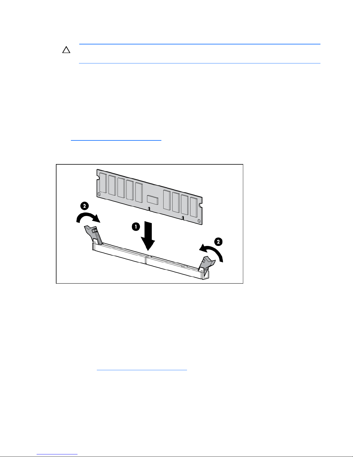
5. Open the DIMM slot latches.
6. Install the DIMM.
air baffle, drive blanks, and access panel must be installed when the server is powered up.
o Unlock and remove the bezel.
o Extend the server from the rack.
For more information, see the server installation sheet on the HP website
(http://www.hp.com/go/bizsupport
).
7. Install the air baffle.
8. Install the access panel.
9. Do one of the following:
o Close or install the tower bezel, as needed.
o Slide the server back into the rack.
If you are installing DIMMs in lock-step configuration, configure this mode in RBSU ("HP ROM-Based
Setup Utility" on page 52).
For more information about LEDs and troubleshooting failed DIMMs, see the server installation sheet on
the HP website (http://www.hp.com/go/bizsupport
Hard drive options
The server provides non-hot-plug capability through an embedded SATA controller. To obtain hot-plug
capability, install an optional controller and hot-plug cable option kit.
).
Hardware options installation 26
Hard drive guidelines
When adding hard drives to the server, observe the following general guidelines:
• The system automatically sets all drive numbers.
• If only one hard drive is used, install it in the bay with the lowest drive number.
• Drives must be the same capacity to provide the greatest storage space efficiency when drives are
grouped together into the same drive array.
Optional storage controllers provide support for hot-plug capability and drive LEDs. Controller options
are:
• The embedded controller supports non-hot-plug SATA hard drives. Drive LEDs are not supported.
• Optional SATA controllers support hot-plug SATA hard drives and drive LEDs.
• Optional SAS controllers support hot-plug SAS or SATA hard drives and drive LEDs.
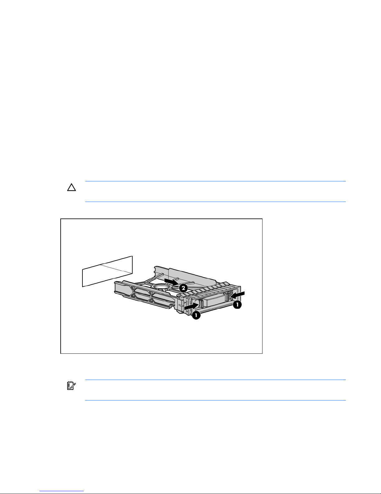
Removing a hard drive blank
CAUTION: To prevent improper cooling and thermal damage, do not operate the server
Remove the component as indicated.
unless all bays are populated with either a component or a blank.
Removing a hard drive
IMPORTANT: Hot-plug capability and drive LED support are only available when a supported
To remove the component:
1. Back up all data on the hard drive.
2. Power down the server (on page 15).
optional controller is installed in the server.
Hardware options installation 27
CAUTION: To prevent improper cooling and thermal damage, do not operate the server
unless all bays are populated with either a component or a blank.
3. Remove the hard drive.
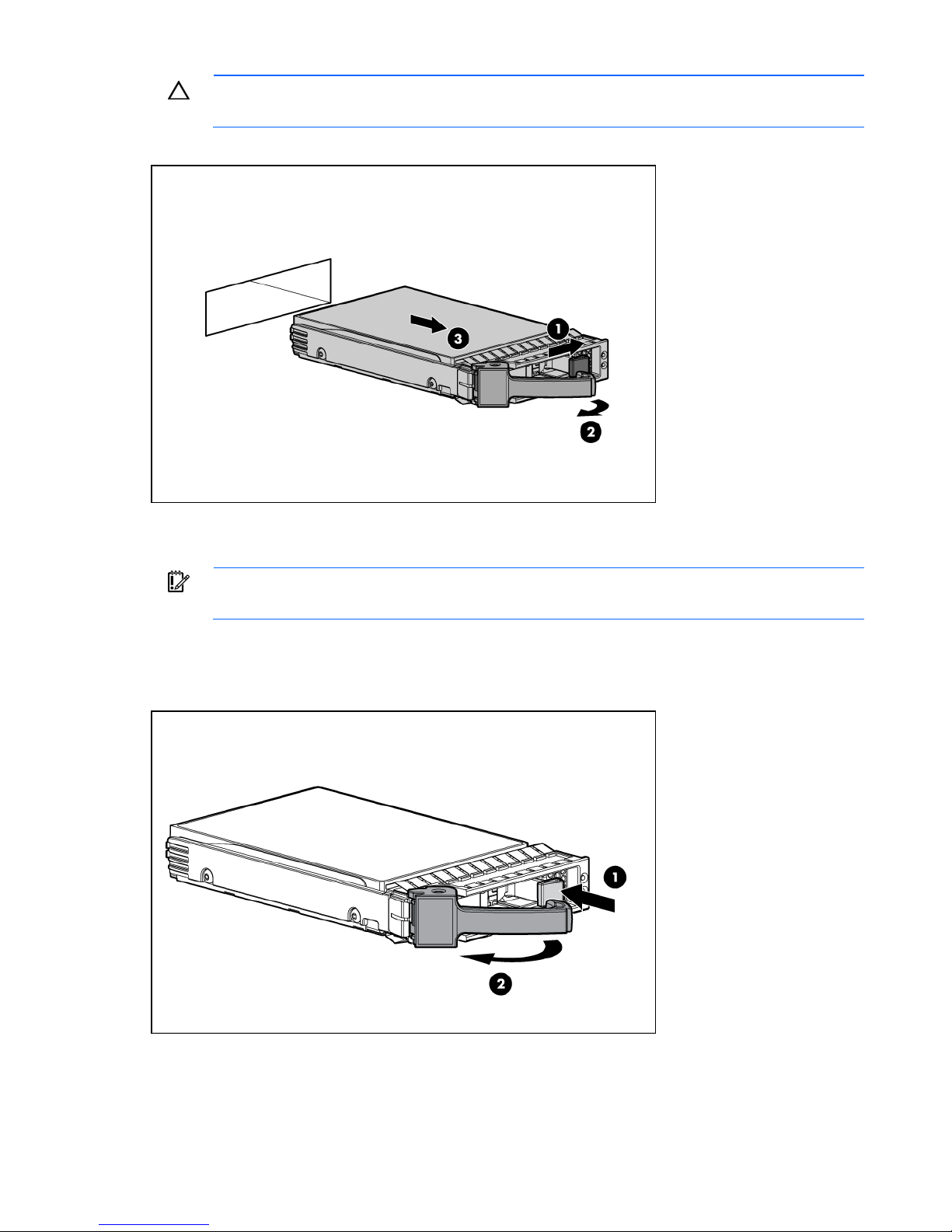
Installing a hot-plug hard drive
IMPORTANT: Hot-plug capability and drive LED support are only available when a supported
1. Power down the server (on page 15).
2. Remove the existing hard drive blank ("Removing a hard drive blank" on page 27).
3. Prepare the hard drive.
optional controller is installed in the server.
Hardware options installation 28
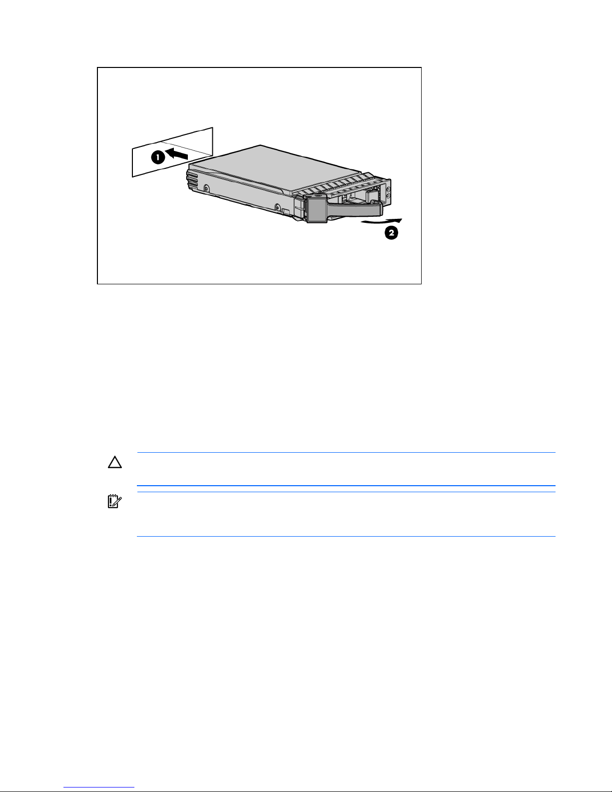
4.
Install the hard drive.
Installing a non-hot-plug hard drive
The server supports up to four SATA hard drives with the embedded controller.
The server supports up to four SAS hard drives with the following options:
• Optional SAS controller
• Optional SAS controller cable
• Optional SAS hard drive LED cable ("SAS hard drive LED cable option" on page 37) (for LED
functionality)
For optimal performance, do not mix SAS and SATA hard drives.
CAUTION: To prevent improper cooling and thermal damage, do not operate the server
To install the component:
1. Power down the server (on page 15).
unless all bays are populated with either a component or a blank.
IMPORTANT: If only one hard drive is installed, install it in the bay with the lowest device
number. For drive installation guidelines, refer to "SAS and SATA hard drive guidelines (on
page 55)."
2. Remove the server from the rack (on page 15).
3. Remove the access panel (on page 16).
Hardware options installation 29
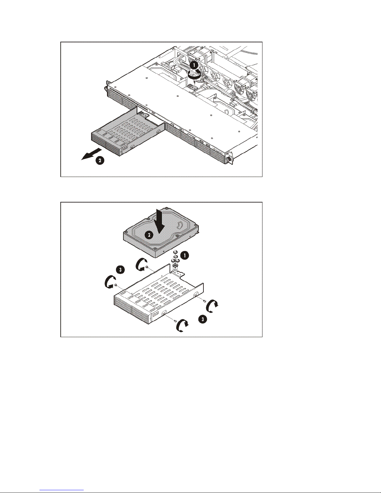
4.
Using a T-10 Torx screwdriver, remove the hard drive carrier.
5. Remove four T-10 screws from the hard drive carrier.
6. Install the hard drive.
Hardware options installation 30
 Loading...