


HP ProLiant Cluster F500 DT Installation Guide
September 2006 (Second Edition)
Part Number 364780-002

© Copyright 2004, 2006 Hewlett-Packard Development Company, L.P.
The information contained herein is subject to change without notice. The only warranties for HP products and services are set forth in the express
warranty statements accompanying such products and services. Nothing herein should be construed as constituting an additional warranty. HP
shall not be liable for technical or editorial errors or omissions contained herein.
Microsoft, Windows, and Windows NT are U.S. registered trademarks of Microsoft Corporation. Windows Server 2003 is a trademark of
Microsoft Corporation. Intel, Pentium, and Itanium are trademarks or registered trademarks of Intel Corporation or its subsidiaries in the United
States and other countries. UNIX is a registered trademark of The Open Group.
September 2006 (Second Edition)
Part Number 364780-002
Audience assumptions
This document is for the person who installs, administers, and troubleshoots servers and storage systems.
HP assumes you are qualified in the servicing of computer equipment and trained in recognizing hazards
in products with hazardous energy levels.

Contents
HP ProLiant Cluster F500 DT for Enterprise Virtual Array overview...................................................... 5
HP ProLiant Cluster F500 for EVA introduction .............................................................................................. 5
Disaster tolerance for EVA..........................................................................................................................5
HP ProLiant Cluster F500 for EVA overview ..................................................................................................5
EVA basic DT configuration ........................................................................................................................ 6
EVA bidirectional DT configuration .............................................................................................................. 7
EVA maximum DT configuration .................................................................................................................. 8
Setting up the ProLiant Cluster F500 for Enterprise Virtual Array......................................................... 9
Required materials..................................................................................................................................... 9
Continuous access..................................................................................................................................... 9
Installing the hardware............................................................................................................................... 9
Preparing the F500 for continuous access EVA hardware installation ...................................................10
Setting up the servers ..................................................................................................................... 10
Setting up the storage subsystem .....................................................................................................10
Setting up the Fibre Channel adapters.............................................................................................. 10
Setting up the Fibre Channel switches at both locations, if applicable................................................... 11
Connecting the controllers to the switches ......................................................................................... 11
Connecting the host to the switches.................................................................................................. 13
Zoning recommendations ...............................................................................................................13
Setting up a bidirectional solution.................................................................................................... 13
Configuring the software.......................................................................................................................... 13
Preparing the F500 for continuous access EVA software installation ..................................................... 14
Logging on to the SAN management appliance................................................................................. 15
Entering a license key .................................................................................................................... 15
Initializing the source site................................................................................................................ 15
Naming the site............................................................................................................................. 15
Creating the VD folders..................................................................................................................16
Creating the VDs........................................................................................................................... 16
Creating the host folder.................................................................................................................. 17
Adding a host............................................................................................................................... 17
Presenting the VDs to the host.......................................................................................................... 17
Discovering the devices.................................................................................................................. 18
Creating the DR groups..................................................................................................................18
Creating the copy sets.................................................................................................................... 18
Creating the managed sets ............................................................................................................. 19
Pre-presenting the destination VDs to cluster nodes....................................................................................... 19
HP ProLiant Cluster F500 for MA8000 Enhanced DT overview ........................................................ 20
HP ProLiant Cluster F500 for MA8000 introduction .....................................................................................20
Disaster tolerance for MA8000................................................................................................................. 20
HP ProLiant Cluster F500 for MA8000 overview ......................................................................................... 20
MA8000 basic DT configuration............................................................................................................... 21
MA8000 bidirectional DT configuration..................................................................................................... 22
MA8000 maximum DT configuration.........................................................................................................23
Setting up the ProLiant Cluster F500 for MA8000........................................................................... 24
Required materials................................................................................................................................... 24
Data Replication Manager........................................................................................................................ 24
Installing the hardware............................................................................................................................. 24
Setting up the servers for MA8000 .................................................................................................. 25
Contents 3

Setting up the storage subsystem .....................................................................................................25
Setting up the host bus adapters ...................................................................................................... 25
Designating the server as a maintenance terminal.............................................................................. 25
Setting up the Fibre Channel switches at both locations ...................................................................... 25
Configuring DRM .................................................................................................................................... 25
Configuring the controllers at the target site ......................................................................................26
Configuring the storage at the target site .......................................................................................... 29
Connecting fiber optic cables between the controllers and switches ..................................................... 29
Connecting the target site to the external fiber link ............................................................................. 29
Connecting the target site to the ATM link......................................................................................... 30
Configuring the host at the target site............................................................................................... 30
Configuring the controllers at the initiator site.................................................................................... 31
Configuring the storage at the initiator site........................................................................................ 34
Connecting fiber optic cables between the controllers and switches ..................................................... 34
Connecting the initiator site to the external fiber link........................................................................... 35
Connecting the initiator site to the ATM link ......................................................................................35
Creating remote copy sets ..............................................................................................................35
Creating log units and association sets (optional)............................................................................... 36
Configuring the Host at the Initiator Site ........................................................................................... 37
Installing Microsoft Cluster Server.............................................................................................................. 39
Documenting the configuration.................................................................................................................. 39
Saving controller information .......................................................................................................... 39
Installing bidirectional storage .................................................................................................................. 40
Adding clusters ....................................................................................................................................... 40
Installing server options .................................................................................................................. 41
Configuring the host at the target site............................................................................................... 41
Configuring the host at the initiator site............................................................................................. 41
Disaster recovery ........................................................................................................................ 42
HP ProLiant Cluster F500 DT for EVA ......................................................................................................... 42
Managing continuous access .......................................................................................................... 42
Failure scenarios ........................................................................................................................... 42
EVA storage failback procedure ...................................................................................................... 45
ISL failback procedure.................................................................................................................... 46
HP ProLiant Cluster F500 DT for MA8000 .................................................................................................. 46
Managing Data Replication Manager .............................................................................................. 47
F500 DT for MA8000 failure scenarios............................................................................................47
Zoning worksheets...................................................................................................................... 51
Site A zoning worksheet........................................................................................................................... 51
Site B zoning worksheet ........................................................................................................................... 51
Connection naming worksheet...................................................................................................... 53
Connection naming worksheet .................................................................................................................. 53
Technical support........................................................................................................................ 54
Before you contact HP.............................................................................................................................. 54
HP contact information............................................................................................................................. 54
Acronyms and abbreviations........................................................................................................ 55
Glossary.................................................................................................................................... 58
Index......................................................................................................................................... 60
Contents 4

HP ProLiant Cluster F500 DT for Enterprise
Virtual Array overview
In this section
HP ProLiant Cluster F500 for EVA introduction ............................................................................................. 5
Disaster tolerance for EVA......................................................................................................................... 5
HP ProLiant Cluster F500 for EVA overview................................................................................................. 5
EVA basic DT configuration....................................................................................................................... 6
EVA bidirectional DT configuration............................................................................................................. 7
EVA maximum DT configuration................................................................................................................. 8
HP ProLiant Cluster F500 for EVA introduction
This guide provides supplemental information for setting up an HP ProLiant Cluster F500 Disaster Tolerant
for EVA configuration using HP StorageWorks Continuous Access EVA software. This guide serves as a
link between the various clustering guides needed to complete a DT cluster installation. Other guides
include:
•
HP ProLiant Cluster F500 Installation Guide
•
Best Practices Guide — ProLiant Cluster HA/F500 for Enterprise Virtual Array (HSV100/HSV110)
Using Microsoft Windows 2000 Advanced Server and Microsoft Windows Server 2003, Enterprise
Edition
•
HP StorageWorks Continuous Access EVA Design Reference Guide
For the latest version of the reference guide and other Continuous Access EVA documentation, access the
HP storage website (http://h18006.www1.hp.com/storage/index.html).
Disaster tolerance for EVA
Disaster-tolerant solutions provide high levels of availability with rapid data access recovery, no single
point of failure, and continued data processing after the loss of one or more system components in a
cluster configuration. Data is simultaneously written to both local and remote sites during normal
operation. The local site is known as the source site because it is in control of the operation. The remote
site is known as the destination site because it is where the information is copied.
Copied data resides at both the source and destination sites. However, in base DT cluster configurations
under normal conditions, host data access occurs only through the source site. Processing will migrate to
the destination site and continue normal operation if a component failure or a catastrophe occurs at the
source site.
HP ProLiant Cluster F500 for EVA overview
The HP ProLiant Cluster F500 DT for EVA configuration is a two-node cluster for Microsoft® Windows®
2000 Advanced Server or a two-to-eight-node cluster for Microsoft® Windows® Server 2003, Enterprise
HP ProLiant Cluster F500 DT for Enterprise Virtual Array overview 5

Edition. The DT configurations use HP ProLiant servers, HP StorageWorks storage subsystems, HP
StorageWorks Continuous Access software, HP OpenView software, and HP StorageWorks Secure Path
software.
This solution combines the failover functionality of Microsoft® Cluster Server with the remote data
mirroring functionality of Continuous Access. This solution also allows for a distance of up to 100 km
between a primary (local) external storage subsystem and a mirrored (remote) external storage subsystem.
The server-to-storage connection is based on a Fibre Channel switch, using a shortwave connection, and
server-to-server communication, using Ethernet over FDDI or FCIP connections. The extended Continuous
Access EVA-over-IP configuration is similar to the simple Continuous Access EVA configuration except for
the use of Fibre Channel-to-IP gateways. Two gateways are required at each site, one per fabric, for a
total of four per solution, dedicated to that solution. When multiport gateways become available, each
port must be dedicated to another single port.
The ProLiant server nodes in the cluster are connected or stretched over a distance. Up to two storage
subsystems for FCIP connections and four storage subsystems for non-FCIP connections can be used at one
site. These storage subsystems act as the source sites for the Continuous Access software and process disk
subsystem requests for all nodes in the cluster. The storage subsystems are connected to the server nodes
by means of redundant Fibre Channel connections that are managed by Secure Path. Additionally, the
source storage subsystems are connected by means of redundant longwave fiber/FCIP connections to the
destination site. As with standard ProLiant clusters using Microsoft® operating systems, MSCS manages
failovers at the server and application levels.
The Continuous Access software functions at the redundant storage controller level in each of the storage
subsystems and performs synchronous mirroring from the source site to the destination site, creating an
exact copy of the cluster-shared disk. A manual recovery process performed at the destination site enables
access to the mirrored data in the event of a disaster at the source site. The cluster is functional again
within minutes, and application processing can continue.
The F500 DT for EVA cluster requires two types of links: network and storage. The first requirement is at
least two network links between the servers. MSCS uses the first network link as a dedicated private
connection to pass heartbeat and cluster configuration information between the servers. The second
network link is a public network connection that clients use to communicate with the cluster nodes. The DT
cluster configuration can use any network card that is supported by Microsoft® operating systems.
However, MSCS requires that the dedicated private link and public link between the servers be located
on different TCP/IP subnets.
Because typical network topologies, such as 100-Mb Ethernet, cannot normally meet this criterion over the
longer distances used in a DT cluster, another topology, such as FDDI or FCIP, must be used. FDDI
network cards can be used in each server in place of the standard Ethernet NICs, or standard Ethernet
NICs can be used to connect to an FDDI concentrator/FCIP switch that will connect the two sites.
The second requirement is the storage link between the storage subsystems. The servers are connected to
the local storage systems, using multimode fiber optic cable. Each storage subsystem is connected to two
Fibre Channel switches at each site in a redundant path configuration using multimode fiber optic cable.
The switches at one site are connected to the switches at the other site by means of single-mode fiber optic
or FCIP connections.
EVA basic DT configuration
The basic DT configuration includes a second destination storage subsystem that mirrors the data on the
source storage subsystem. The basic DT configuration consists of:
•
Two ProLiant servers as cluster nodes
•
Two storage subsystems
•
Four HP StorageWorks Fibre Channel SAN switches (for a current list of supported switches, refer to
the High Availability website) (http://www.hp.com/servers/proliant/highavailability
)
HP ProLiant Cluster F500 DT for Enterprise Virtual Array overview 6
Two FCAs in each server
•
•
Two storage management appliances, at least one for each site
A basic DT cluster configuration consists of two separated nodes. The two nodes, plus the source storage
subsystem, form an MSCS cluster.
EVA bidirectional DT configuration
The bidirectional DT configuration enables a source subsystem to also be configured as a destination
subsystem. The bidirectional DT configuration consists of:
•
Two ProLiant servers as cluster nodes
•
Two storage subsystems
•
Four HP StorageWorks Fibre Channel switches
•
Two FCAs in each server
•
Two SMAs, at least one for each site
NOTE: Refer to the HP StorageWorks Continuous Access EVA Design Reference Guide for complete lists of
supported equipment.
HP ProLiant Cluster F500 DT for Enterprise Virtual Array overview 7
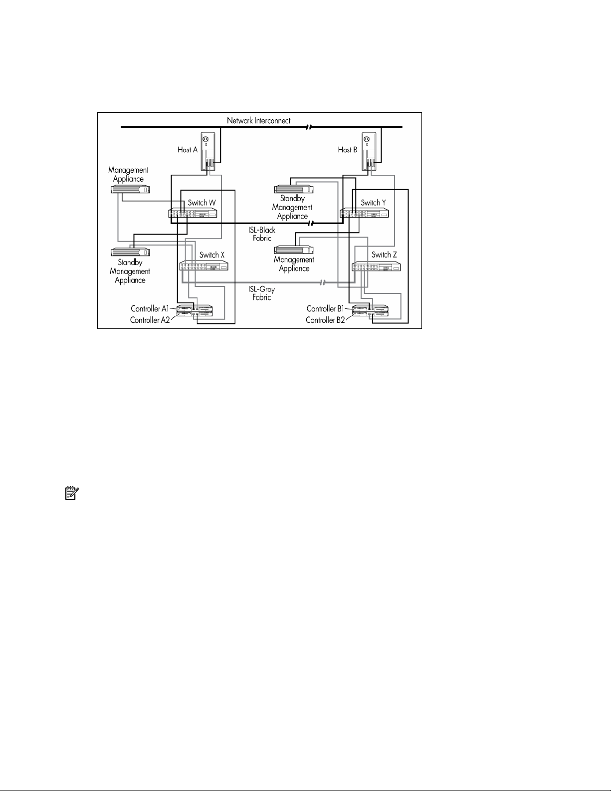
A bidirectional DT configuration consists of two separated nodes. As in the basic DT configuration, data
at the first site is mirrored on a second storage subsystem at the second site. Two storage systems can
communicate bidirectionally, meaning that a storage system can be used as the primary source for data
and as a destination for data replication. By providing redundant systems and software, as well as
alternate paths for data flow, high availability and disaster tolerance is achieved with no single point of
failure.
EVA maximum DT configuration
Refer to the High Availability website (http://www.hp.com/servers/proliant/highavailability) or HP
StorageWorks Continuous Access EVA Design Reference Guide for maximum configuration information.
HP ProLiant Cluster F500 DT for Enterprise Virtual Array overview 8

Setting up the ProLiant Cluster F500 for Enterprise Virtual Array
In this section
Required materials.................................................................................................................................... 9
Continuous access.................................................................................................................................... 9
Installing the hardware ............................................................................................................................. 9
Configuring the software......................................................................................................................... 13
Pre-presenting the destination VDs to cluster nodes ..................................................................................... 19
Required materials
To configure an F500 DT cluster for Continuous Access, you will need any applicable documents listed in
the "Related Documents" section of the HP Continuous Access EVA Getting Started Guide. Many of the
referenced documents will be online.
The following is a short list of essential documents.
•
HP Continuous Access EVA Getting Started Guide
•
HP ProLiant Cluster F500 Installation Guide
•
HP StorageWorks Continuous Access EVA Design Reference Guide
•
HP StorageWorks Continuous Access User Interface Installation Guide
•
HP StorageWorks Continuous Access User Interface Release Notes
•
HP StorageWorks Command View EVA documentation, including online help
•
HP StorageWorks Continuous Access Management User Interface online help
•
HP StorageWorks Secure Path for Windows installation guide
•
Fibre Channel SAN Switch installation and hardware guide
Continuous access
Refer to the HP StorageWorks Continuous Access EVA Operations Guide for detailed information on
Continuous Access, including any restrictions.
Installing the hardware
Depending on the size of your SAN and the considerations used in designing it, many different hardware
configurations are possible. Refer to the HP StorageWorks Continuous Access Enterprise Virtual Array
Design Reference Guide for a detailed description of various hardware configurations.
Set up the cluster using the following procedures:
1.
"Preparing the F500 for continuous access EVA hardware installation (on page 10)"
2.
"Setting up the servers (on page 10)"
Setting up the ProLiant Cluster F500 for Enterprise Virtual Array 9

"Setting up the storage subsystem (on page 10)"
3.
4.
"Setting up the Fibre Channel adapters (on page 10)"
5.
"Setting up the Fibre Channel switches at both locations, if applicable (on page 11)"
6.
"Connecting the controllers to the switches (on page 11)"
7.
"Connecting the host to the switches (on page 13)"
8.
"Zoning recommendations (on page 13)"
9.
"Setting Up a Bidirectional Solution (on page 13)"
Preparing the F500 for continuous access EVA hardware installation
Task Reference document
Set up EVA storage system hardware. HP StorageWorks Enterprise Virtual Array User Guide
Make fabric connections:
• Connect GBICs or small form factor pluggables
to switch ports.
• Connect HSV controller pair, SMA, and hosts to
Fibre Channel fabrics.
• HP StorageWorks Continuous Access EVA
Operations Guide
• Compaq SANworks Management Appliance
Getting Started Guide
• Test intersite links.
Install intersite links and connect to switches with
GBICs or SFPs.
Install host kits and device drivers, if required.
Upgrade drivers if necessary.
HP StorageWorks SAN Extension Using FCIP
Configuration Guide
OS-specific kit version 3.x for EVA installation and
configuration guide
Install Fibre Channel adapters. FCA documentation
Create separate management zones for any HSG80
HP StorageWorks SAN Design Reference Guide
systems in your SAN.
Plan and populate layout of one or more physical
disk groups.
Power up storage systems and SMAs.
HP StorageWorks Continuous Access EVA Operations
Guide
• HP ProLiant Cluster F500 Installation Guide
• Compaq SANworks Management Appliance
Getting Started Guide
Setting up the servers
To prepare the Continuous Access solution for setup, refer to the ProLiant cluster documentation. Follow
the installation instructions in the ProLiant server documentation.
Setting up the storage subsystem
Refer to the documentation that was shipped with the storage subsystem for detailed installation
instructions.
Setting up the Fibre Channel adapters
Two FCAs must be installed on each host. For detailed installation instructions, refer to the documentation
that comes in the host kit or with your adapter.
Locate and record the World Wide Names of each FCA on the zoning worksheet. Keep a copy of the
worksheets at all your sites. In addition, record the WWNs for the EVA and the SMAs for each site.
Setting up the ProLiant Cluster F500 for Enterprise Virtual Array 10
NOTE: The WWN can be found on the bottom of the adapter board. Look for a small bar code label with
an IEEE precursor. A WWN example is 1000-0000-C920-A5BA.
Setting up the Fibre Channel switches at both locations, if applicable
NOTE: Both Fibre Channel switches can be configured from the same site.
Your Fibre Channel switches must be installed and configured with two working redundant fabrics before
you connect the remaining Continuous Access EVA components to your fabrics. For information on the
specific switches used and GBICs needed, refer to the HP website
(http://h18006.www1.hp.com/storage/saninfrastructure.html
).
Connecting the controllers to the switches
Before connecting fiber optic cables between storage components, HP recommends that you tag each end
to identify switch names, port numbers, controller names, and so on.
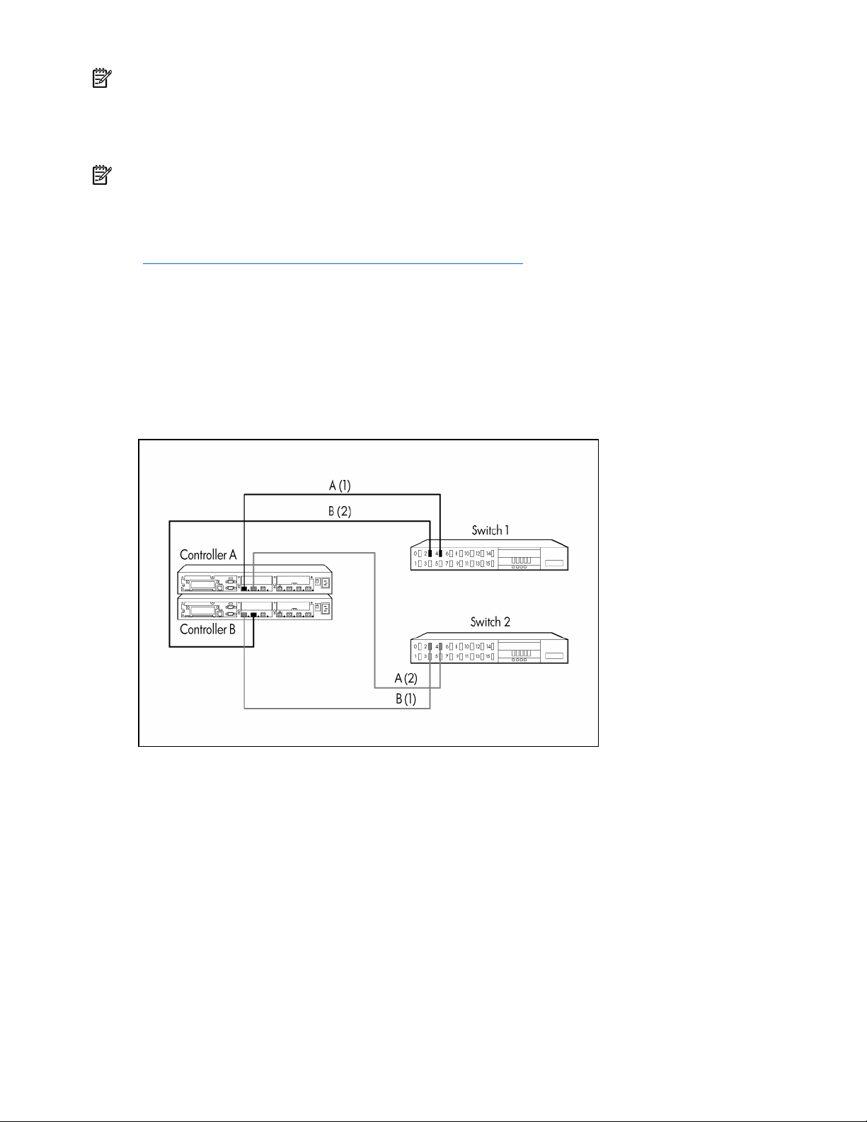
Four fiber optic cable connections are required for each controller pair. The only supported connection
scheme is shown below. Connect the fiber optic cable such that port 1 of controller A and controller B go
to different fabrics. Connect port 2 of controller A and controller B to separate fabrics that are the fabric
opposite from port 1 on that controller.
The basic rule is that the first or left-hand port on the top controller is cabled to the first fabric and the
other port of the same controller is cabled to the other fabric. The other (bottom) controller is cabled such
that the left-hand port is attached to the second fabric, while the second port is cabled to the first fabric,
the opposite of the first (top) controller. Even though it does not matter which switch ports are used,
symmetry is recommended.
Either controller can be controller A or controller B. In a storage system that has not been configured, the
first controller that powers up and passes a self-test becomes controller A. Also, under certain conditions,
controller A and controller B can have their designations reversed.
Setting up the ProLiant Cluster F500 for Enterprise Virtual Array 11
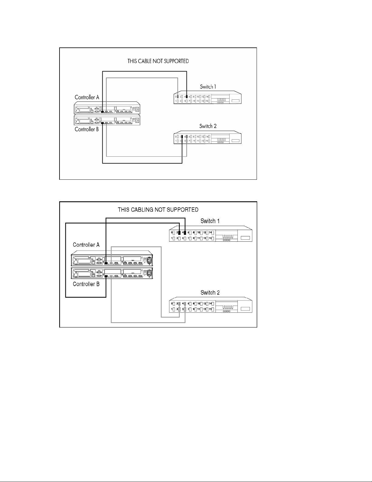
Any other controller-to-fabric cabling scheme is not supported. The cabling in the following example is not
supported because both port 1s share the same fabric and both port 2s share the same fabric.
The cabling in the following example is not supported because both ports of a controller are on the same
fabric, limiting failover options when there is a fabric issue.
You can control the power sequence of the controllers in your storage system, thereby forcing a controller
designation. To guarantee that a particular controller is designated controller A:
1.
Uninitialize the storage system. If it is a new storage system that has never been initialized, this step
is not necessary.
2.
Power off both controllers.
3.
Pull out and reseat the cache batteries on the controller you want to designate controller A. This
procedure clears the cache.
4.
Power up that controller.
5.
After controller A passes the self-test, power up the other controller.
Setting up the ProLiant Cluster F500 for Enterprise Virtual Array 12

Connecting the host to the switches
Tag each end of your fiber optic cable to identify switch names, port numbers, host names, and so on.
Two fiber optic connections are required for each host. Connect the fiber optic cable such that
connections to the two FCAs go to two separate switches (fabrics).
Zoning recommendations
Having both fabrics in place and operational is necessary before you even begin any other equipment
installation. For information on fabric topologies, fabric design rules, and switch zoning, refer to the HP
StorageWorks SAN Design Reference Guide.
For Continuous Access-specific guidelines, refer to the HP StorageWorks Continuous Access EVA
Operations Guide.
Zoning is a logical grouping of end-to-end Fibre Channel connections, implemented by switches, to create
a barrier between different environments and allow for finer segmentation of the fabric. Switch ports that
are members of a zone can communicate with each other but are isolated from ports in other zones.
Because the SMA and hosts in a Continuous Access EVA environment can conflict with each other, they
must reside in separate zones.
NOTE: If any HSG80 controllers with DRM reside within the SAN, they must be zoned out of an EVA
fabric.
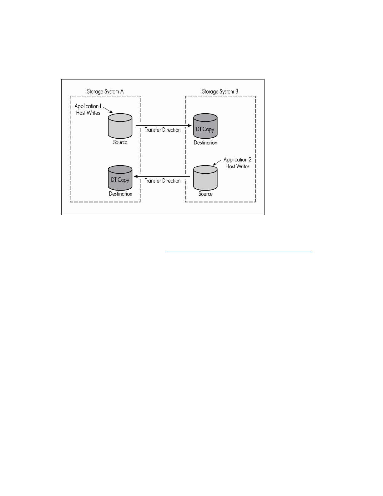
Setting up a bidirectional solution
You can configure data replication groups to replicate data from storage system A to storage system B
and other unrelated data replication groups to replicate data from storage system B back to storage
system A. This feature, called bidirectional replication, enables a storage system to have both source and
destination virtual disks, where these Vdisks belong to separate Data Replication groups. This setup has
no effect on normal operation or failover policy and has the advantage of allowing for the destination
storage system to be actively used while also providing a disaster-tolerant copy of the other site's data. If
the business needs require bidirectional data transfers, you must determine the effect on the links.
Refer to the Continuous Access EVA Design Reference Guide for more information.
Configuring the software
The storage system must be initialized before it can be used. This process binds the controllers together as
an operational pair and establishes preliminary data structures on the disk array.
Initialization is performed through the use of the Command View EVA. This procedure is documented in
the HP StorageWorks Command View EVA Getting Started Guide. HP StorageWorks Command View
EVA maintains a database that resides on the management appliance and is accessible only by the
element manager for each storage system.
The Command View EVA software can be installed on more than one management appliance in a fabric.
Each installation of the Command View EVA software is a management agent. The client for the agent is
a standard browser.
To begin the configuration process, create, or initialize, the storage system. When you first view the EVA
from the Command View EVA software, the storage pool is presented as "uninitialized storage."
Before the host servers can use the virtual disks, you must:
•
Initialize the storage systems at both the source and destination. The storage pool is "uninitialized
storage" at the outset.
Setting up the ProLiant Cluster F500 for Enterprise Virtual Array 13

Add hosts to the storage system.
•
•
Create and present virtual disks to hosts.
Configure the software using the following procedures:
1.
"Preparing the F500 for Continuous Access EVA Software Installation (on page 14)"
2.
"Logging On to the SAN Management Appliance (on page 15)"
3.
"Entering a License Key (on page 15)"
4.
"Initializing the Source Site (on page 15)"
5.
"Naming the Site (on page 15)"
6.
"Creating the VD Folders (on page 16)"
7.
"Creating the VDs (on page 16)"
8.
"Creating the Host Folder (on page 17)"
9.
"Adding a Host (on page 17)"
10.
"Presenting the VDs to the Host (on page 17)"
11.
"Discovering the Devices (on page 18)"
12.
"Creating the DR Groups (on page 18)"
13.
"Creating the Copy Sets (on page 18)"
14.
"Creating the Managed Sets (on page 19)"
15.
"Pre-presenting the Destination VDs to Cluster Nodes (on page 19)"
Preparing the F500 for continuous access EVA software installation
Task Reference document
Install latest version of system software:
• HP OpenView Storage Management
Appliance Software
• HP StorageWorks Virtual Controller Software
Install HP StorageWorks Secure Path for
Windows® for your platform.
Install HP StorageWorks Continuous Access User
Interface.
Enter storage system WWN into controller using
the Operator Control Panel.
Configure one switch zone encompassing the
active SMA and all storage systems.
Configure one switch zone for each operating
system/host and the storage systems.
Install Command View EVA and set up agents and
user options.
HP OpenView Storage Management Appliance Software
User Guide
EVA Read Me First
EVA Release Notes
HP StorageWorks system software for EVA installation
card
HP StorageWorks upgrade instructions for EVA
HP StorageWorks Secure Path for Windows® platform-
specific installation guide
HP StorageWorks Continuous Access User Interface
Installation Guide
HP ProLiant Cluster F500 DT Installation Guide
HP StorageWorks SAN Design Reference Guide, 4th
Edition
Compaq StorageWorks Switch Zoning Reference Guide
HP StorageWorks SAN Design Reference Guide, 4th
Edition
Compaq StorageWorks Switch Zoning Reference Guide
HP StorageWorks Command View EVA Getting Started
Guide
Setting up the ProLiant Cluster F500 for Enterprise Virtual Array 14

Logging on to the SAN management appliance
1.
Log on to the management appliance by opening a browser and accessing the management
appliance remotely by entering the IP address (or the network name if a DNS is configured) as the
URL. The logon screen opens.
2.
Click anonymous.
3.
Log in as administrator.
4.
Enter the password for the account.
5.
Click OK. The hp openview storage management appliance window displays.
Entering a license key
You must enter a license key encoded with the WWN of the storage system before you initialize the
storage system.
Follow the "Obtaining a License Key" instructions in the HP StorageWorks Enterprise Virtual Array
Licensing Guide.
Each license key belongs to a specific WWN, so enter a license key that matches the WWN of the
storage system. You can enter the license keys for all storage systems that this management agent will
control at the same time.
NOTE: The WWN number must be entered exactly as it appears on the label. This field is case-sensitive.
License keys require an ASCII text editor to ensure their format.
To enter a license key:
1.
Click Agent Options in the Session pane. The Management Agent Options window displays.
2.
Click Licensing Options. The Licensing Options window displays.
3.
Click Enter new license key. The Add a License window displays.
4.
Enter the license key.
You must enter the license key exactly as it was in the e-mail you received from the license key
fulfillment website. If possible, copy the license key from the e-mail and paste it into the text field.
5.
Click Add license. The license key is added.
6.
To enter additional license keys, repeat steps 4 and 5.
Initializing the source site
The procedures to initialize the source site are as follows:
Using the Command View EVA
•
Naming the site
•
Creating the VD folder
•
Creating the Host folder
•
Creating the Disk group folder
Using the Continuous Access GUI
•
Creating the DR Group folder
Naming the site
In the hp openview storage management appliance window:
1.
Click Devices. The Devices window displays.
Setting up the ProLiant Cluster F500 for Enterprise Virtual Array 15

Click command view eva. The HSV Storage Network Properties window displays. You can now
2.
browse the EVAs in the Uninitialized Storage System in the navigation panel.
3.
Determine which site is to be designated Site A and which is to be designated Site B by selecting
Hardware>Controller Enclosure. The Initialize an HSV Storage System window displays.
4.
Enter any requested license key information. Refer to "Entering a license key (on page 15)."
5.
In the Step 1: Enter a Name field, enter the site name.
6.
In the Step 2: Enter the number of disks field, enter the maximum number of disks (minimum of eight
in a disk group) or the number of disks you will use in the default disk group.
NOTE: You must determine if you will configure your storage in a single disk group or multiple disk groups.
CAUTION: Do not use the browser Back button because you will undo the previous operation.
7.
Select Advanced Options to set up the clock.
IMPORTANT: Set up the clock on both EVAs to pull time from the same source.
8.
Click Next. Request a disk failure protection level.
NOTE: HP recommends selecting double for disk failure protection.
9.
Click Finish, and then click OK (if the operation was successful).
NOTE: If the operation is not successful, it typically is caused by a communication problem. Verify the SAN
connection, fix the problem, and begin again at step 1.
Creating the VD folders
1.
In the Command View EVA navigation pane, click Virtual Disks. The Create a Folder window
displays.
2.
In the Step 1: Enter a Name field, enter the folder name (use the cluster name).
3.
In the Step 2: Enter comments field, enter any additional information.
4.
Select Finish>OK.
Creating the VDs
You are given the opportunity to select a preferred path during the creation of a Vdisk. This means that
host I/O to a Vdisk will go to the controller you designate as preferred, as long as the paths to that
controller are available. There are five possible preferred path settings. However, the Windows®
environment enables only those shown in the bulleted list, as Secure Path is responsible for supporting
failback capability.
NOTE: For path A and B, all members of a DR group must have the same preferred path.
•
None (not recommended)
•
Path A—Failover only
•
Path B—Failover only
1.
In the Command View EVA navigation pane, click the new VD folder. The Create a Vdisk Family
window displays.
2.
In the Vdisk name: field, enter the VD name.
3.
In the Size: field, enter the size in gigabytes.
4.
In the Preferred path/mode: dropdown menu, make a selection (for load balancing).
NOTE: All members of DR group must have same setting.
Setting up the ProLiant Cluster F500 for Enterprise Virtual Array 16

Click Create More and repeat steps 2 through 4 for each VD you create.
5.
6.
Select Finish>OK.
NOTE: The Continuous Access software will create the Site B VDs.
Creating the host folder
Create a host folder for each cluster to enable ease of administration.
1.
Click Create Folder. The Create a Folder window displays.
2.
In the Step 1: Enter a Name field, enter SiteA or any name up to 32 characters long.
3.
In the Step 2: Enter comments field, enter any additional information, up to 64 characters long.
4.
Select Finish>OK.
5.
Repeat steps 1 through 4 for all remaining clusters.
Adding a host
NOTE: If the SAN appliance cannot see the host WWNs, perform steps 1 and 2. Otherwise, begin at step
3.
1.
Reboot the SAN appliance.
2.
Access the Command View EVA application.
3.
Click the desired host in the navigation pane. The Add a Host window displays.
4.
In the Host name: field, enter the host name.
5.
In the Host IP address: dropdown menu, select the appropriate scheme or enter the IP address if it is
a static IP address.
6.
In the Port WW Name: dropdown menu, select a port WWN for the first FCA.
7.
Click Add Host, and then click OK. The Add a Host Port window displays.
8.
For each FCA:
a.
In the Click to select from list dropdown menu, select the appropriate FCA.
b.
Click Add port.
9.
Select the Ports tab (which displays only after selecting to add the port) and verify the ports are
correctly assigned.
10.
Repeat the procedure for Site B.
Presenting the VDs to the host
CAUTION: Shut down all the nodes. Only one node should see the drives at one time.
1.
In the Command View EVA navigation pane, click the first new VD. The Vdisk Active Member
Properties window displays.
2.
Click Presentation. The Vdisk Active Member Properties window displays.
3.
Click Present. The Present Vdisk window displays.
4.
Select both hosts, and then click Present Vdisk.
5.
Click OK. You are returned to the Vdisk Active Members Property window.
6.
Select the Presentation tab to verify that both hosts are on the same LUN. The Vdisk Active
Members Property window displays.
7.
Repeat steps 1 through 6 for each VD.
Setting up the ProLiant Cluster F500 for Enterprise Virtual Array 17

Power on Node 1.
8.
9.
Log on to the domain.
10.
Wait until all the VDs are discovered.
11.
Open the operating system Device Manager and look at that disk drive.
12.
Go to the operating system Disk Manager and select Initialize, do not upgrade to dynamic
disk.
13.
Format the disk and label the volumes.
14.
Install MSCS on Node 1. Refer to the appropriate documentation.
15.
Repeat steps 8 through 14 for Node 2.
16.
Join Node 2 to the cluster.
Discovering the devices
You will be creating the copy sets and DR groups in the same sequence.
1.
In the HP OpenView Storage Management Appliance window, click Tools.
2.
Click continuous access. The Continuous Access Status window displays. The window is empty.
NOTE: You are now working in the Continuous Access user interface, not the Command View EVA.
3.
Click Refresh>Discover. A pop-up window informs you that the discovery process could be
lengthy.
After the system has discovered the devices, you will create the DR groups and copy sets.
NOTE: You must plan how to separate managed sets and copy sets. Refer to the HP StorageWorks
Continuous Access EVA Operations Guide.
Creating the DR groups
You can create the DR groups first or create the initial copy set, which forces the DR group creation
process.
The following procedure is for creating the DR groups before the copy sets.
1.
On the Continuous Access window, select the site from the navigation pane.
2.
Click Create>DR Group. The Create a new DR Group window opens.
3.
In the DR Group: field, enter the name.
4.
In the Destination Storage System: dropdown list, select the destination site.
5.
In the Comments: field, enter any comments.
6.
Click Next.
7.
Select Finish>OK.
8.
Repeat the procedure for each DR group.
Creating the copy sets
NOTE: Entering the first copy set will force the DR group creation sequence if no DR Group has yet been
created.
1.
On the Continuous Access window, select the site from the navigation pane.
2.
Click Create>Copy Set. The Create a new Copy Set window opens.
3.
In the DR Group: dropdown list, select the DR group to which the copy set will belong.
Setting up the ProLiant Cluster F500 for Enterprise Virtual Array 18

In the Copy Set: field, enter the copy set name.
4.
5.
Select the source VD from the Source Virtual Disk: dropdown list.
6.
Enter the DR Group.
7.
Select the destination from the Destination Storage System: dropdown list (Site B, if you have
followed suggested naming conventions).
8.
Click Finish.
Creating the managed sets
A managed set is a folder created to hold DR groups. One or more DR groups can be combined to create
a managed set.
1.
Choose Create>Managed Sets. The Edit or create a Managed Set window displays.
2.
In the Managed Set Name: field, enter the name.
3.
Click Finish.
4.
Repeat the procedure for each managed set to create.
5.
In the navigation pane, select the first DR group to be part of a managed set.
6.
In the Configuration dropdown menu, select Edit. The Edit an existing DR Group window displays.
7.
Select a managed set from the Managed Set list, and then click Finish.
8.
Repeat steps 5 through 7 for each DR group to add.
Pre-presenting the destination VDs to cluster nodes
1.
In the hp openview storage management appliance window, select Devices. The Devices window
displays.
2.
Click command view eva. The command view eva Properties window opens.
3.
In the navigation pane, select the destination subsystem, and then click Virtual Disks.
4.
Select the virtual disk to present on the destination subsystem.
5.
Select Active. The Vdisk Active Member Properties window displays.
6.
Select the Presentation tab, and then click Present. The Present Vdisk window opens.
7.
Select the VDs, and then click Present Vdisk.
8.
Click OK.
9.
Repeat for each VD to present.
10.
Verify the disks are properly presented.
a.
In the navigation pane, select the host to verify.
b.
Select the Presentation tab. The Host Properties window displays.
c.
Verify that each VD is presented to a unique LUN.
The configuration is complete.
Setting up the ProLiant Cluster F500 for Enterprise Virtual Array 19

HP ProLiant Cluster F500 for MA8000 Enhanced DT overview
In this section
HP ProLiant Cluster F500 for MA8000 introduction.................................................................................... 20
Disaster tolerance for MA8000................................................................................................................ 20
HP ProLiant Cluster F500 for MA8000 overview........................................................................................ 20
MA8000 basic DT configuration.............................................................................................................. 21
MA8000 bidirectional DT configuration.................................................................................................... 22
MA8000 maximum DT configuration........................................................................................................ 23
HP ProLiant Cluster F500 for MA8000 introduction
This guide provides supplemental information for setting up an HP ProLiant Cluster F500 DT for MA8000
configuration, and it is a link between the various clustering guides needed to complete a DT cluster
installation. These guides include the following:
•
Data Replication Manager HSG80 ACS operations guide
•
StorageWorks HSG80 Array Controller ACS configuration guide
•
StorageWorks HSG80 Array Controller CLI reference guide
•
HP ProLiant Cluster F500 Installation Guide
This guide includes additional installation instructions and references to these guides to complete the setup
of an F500 DT for MA8000 cluster.
Disaster tolerance for MA8000
Disaster-tolerant solutions provide high levels of availability with rapid data access recovery, no single
point of failure, and continued data processing after the loss of one or more system components in a
cluster configuration. Data is simultaneously written to both local and remote sites during normal
operation. The local site is known as the initiator site because it is in control of the operation. The remote
site is known as the target site because it is where the information is copied.
Copied data resides at both the initiator and target sites. However, in base DT cluster configurations
under normal conditions, host data access occurs only through the initiator site. Processing will migrate to
the target site and continue normal operation if a component failure or a catastrophe occurs at the
initiator site.
HP ProLiant Cluster F500 for MA8000 overview
The HP ProLiant Cluster F500 DT for MA8000 configuration is a two-node cluster for Windows® 2000
Advanced Server. The DT configurations use HP ProLiant servers, StorageWorks storage subsystems,
StorageWorks Data Replication Manager software, and StorageWorks Secure Path software.
HP ProLiant Cluster F500 for MA8000 Enhanced DT overview 20

This solution combines the failover functionality of Microsoft® Cluster Server with the remote data
mirroring functionality of DRM. This solution also allows for a distance of up to 100 km between the
server nodes and between a primary (local) external storage subsystem and a mirrored (remote) external
storage subsystem. The server-to-storage connection is based on a Fibre Channel switch using a
shortwave connection and server-to-server communication using Ethernet over FDDI or ATM connections.
The HP ProLiant server nodes in the cluster are connected or stretched over a distance. Up to two storage
subsystems for ATM connections and four storage subsystems for non-ATM connections can be used at
one site. These storage subsystems act as the initiator sites for the DRM software and process disk
subsystem requests for all nodes in the cluster. The storage subsystems are connected to the server nodes
by means of redundant Fibre Channel connections that are managed by Secure Path. Additionally, the
initiator storage subsystems are connected by means of redundant longwave fiber/ATM connections to
the target site. As with standard HP ProLiant Clusters using Microsoft® operating systems, MSCS manages
failovers at the server and application levels.
The DRM software functions at the redundant storage controller level in each of the storage subsystems
and performs synchronous mirroring from the initiator site to the target site, creating an exact copy of the
cluster-shared disk. A manual recovery process performed at the target site enables access to the mirrored
data in the event of a disaster at the initiator site. The cluster is functional again within minutes, and
application processing can continue.
The F500 DT for MA8000 cluster requires two types of links: network and storage. The first requirement is
for at least two network links between the servers. MSCS uses the first network link as a dedicated private
connection to pass heartbeat and cluster configuration information between the servers. The second
network link is a public network connection that clients use to communicate with the cluster nodes. The DT
cluster configuration can use any network card that is supported by Microsoft® operating systems.
However, MSCS requires that the dedicated private link and public link between the servers be located
on the same TCP/IP subnet.
Because typical network topologies, such as 100 Mb Ethernet, cannot normally meet this criterion over
the longer distances used in a DT cluster, another topology, such as FDDI or ATM must be used. FDDI
network cards can be used in each server in place of the standard Ethernet NIC cards, or standard
Ethernet NICs can be used to connect to an FDDI concentrator/ATM switch that will connect the two sites.
This type of configuration supports the longer distances used in a DT cluster and meets the requirement for
keeping the servers on the same TCP/IP subnet.
The second requirement is the storage link between the storage subsystems. The servers are connected to
the local storage systems using multimode fiber optic cable. Each storage subsystem is connected to two
Fibre Channel switches at each site in a redundant path configuration using multimode fiber optic cable.
The switches at one site are connected to the switches at the other site by means of single-mode fiber optic
or ATM connections.
MA8000 basic DT configuration
The basic DT configuration includes a second target storage subsystem that mirrors the data on the
initiator storage subsystem. The basic DT configuration consists of:
•
Two HP ProLiant servers as cluster nodes
•
Two storage subsystems
•
Four StorageWorks Fibre Channel SAN Switch 8/8-EL or SAN Switch 16/16-EL switches
•
Two host bus adapters in each server
•
Two storage controllers in each storage subsystem
HP ProLiant Cluster F500 for MA8000 Enhanced DT overview 21

A basic DT configuration consists of two separated nodes. The two nodes plus the initiator storage
subsystem form an MSCS cluster.
MA8000 bidirectional DT configuration
The bidirectional DT configuration adds two storage subsystems to the basic DT configuration. The
bidirectional DT configuration consists of:
•
Two HP ProLiant servers as cluster nodes
•
Four storage subsystems
•
Four StorageWorks Fibre Channel SAN Switch 8/8-EL or SAN Switch 16/16-EL switches
•
Two host bus adapters in each server
•
Two storage controllers in each storage subsystem
HP ProLiant Cluster F500 for MA8000 Enhanced DT overview 22

A bidirectional DT configuration consists of two separated nodes. As in the basic DT configuration, data
at the first site is mirrored on a second storage subsystem at the second site. The bidirectional DT solution
adds an initiator storage subsystem at the second site. This storage subsystem is mirrored at the first site
on a fourth storage subsystem (a target site). The first initiator-target pair of storage subsystems mirrors
data from the first site to the second site, while the second initiator-target pair of storage subsystems
mirrors data from the second site to the first site.
MA8000 maximum DT configuration
Refer to the High Availability website (http://www.hp.com/servers/proliant/highavailability) for
maximum configuration information.
HP ProLiant Cluster F500 for MA8000 Enhanced DT overview 23

Setting up the ProLiant Cluster F500 for MA8000
In this section
Required materials.................................................................................................................................. 24
Data Replication Manager ...................................................................................................................... 24
Installing the hardware ........................................................................................................................... 24
Configuring DRM ................................................................................................................................... 25
Installing Microsoft Cluster Server............................................................................................................. 39
Documenting the configuration................................................................................................................. 39
Installing bidirectional storage ................................................................................................................. 40
Adding clusters ...................................................................................................................................... 40
Required materials
To configure an F500 DT cluster for DRM, you will need the following guides:
•
HP ProLiant Cluster F500 Installation Guide
•
Data Replication Manager HSG80 ACS operations guide
•
StorageWorks HSG80 Array Controller ACS configuration guide
•
StorageWorks HSG80 Array Controller ACS maintenance and service guide
•
StorageWorks HSG80 Array Controller ACS CLI reference guide
•
StorageWorks Command Console getting started guide
•
StorageWorks Secure Path for Windows installation guide
•
Fibre Channel SAN Switch installation and hardware guide
Data Replication Manager
Refer to the Data Replication Manager HSG80 ACS operations guide for detailed information on the
Data Replication Manager including any restrictions.
Installing the hardware
Set up the cluster using the following procedures:
1.
"Setting up the servers for MA8000 (on page 25)"
2.
"Setting up the storage subsystem (on page 10)"
3.
"Setting up the host bus adapters (on page 25)"
4.
"Designating the server as a maintenance terminal (on page 25)"
5.
"Setting up the Fibre Channel switches at both locations (on page 25)"
Setting up the ProLiant Cluster F500 for MA8000 24

Setting up the servers for MA8000
Refer to the Data Replication Manager HSG80 ACS operations guide for DRM installation information
needed to get the DRM solution ready for setup.
Follow the installation instructions in the HP ProLiant server documentation to set up each server as a
stand-alone server, and then follow the instructions in the following sections to configure the cluster.
Setting up the storage subsystem
Refer to the documentation that was shipped with the storage subsystem for detailed installation
instructions.
Setting up the host bus adapters
Install two host bus adapters into the host server to run the DRM solution. Refer to the host bus adapter
guide for detailed information on this hardware.
Locate and record the WWN of each host bus adapter on the Connection naming worksheet (on page
53). This number will be needed when renaming the host connections later in the installation process.
NOTE: The WWN can be found on the bottom of the adapter board. Look for a small bar code label with
an IEEE precursor. A WWN example is 1000-0000-C920-A5BA.
Designating the server as a maintenance terminal
A server must be connected to the storage controller to provide a maintenance terminal.
NOTE: Only one server should be designated as the maintenance terminal. It is recommended that a
separate stand-alone server that is not part of the cluster be designated as the maintenance server.
1.
Connect the RJ-12 connector on the communications cable to the maintenance port on the storage
controller.
2.
Connect the 9-pin serial connector on the communications cable to either the COM1 or COM2 port
on the server.
NOTE: Record which serial port is used. This information will be needed when setting up the
communications program and configuring the controller.
Setting up the Fibre Channel switches at both locations
Refer to the documentation that was shipped with the switches for detailed switch installation instructions.
To set up the Fibre Channel switches at both locations:
1.
Turn on the AC power for each switch.
2.
Enter the IP addresses and subnet masks for each switch. Each switch must have a different IP
address.
Configuring DRM
A command line interface must be present on both the target and initiator sites before you begin the
configuration process. Refer to the Data Replication Manager HSG80 ACS operations guide for detailed
DRM configuration instructions.
Set up DRM using the following procedures:
Setting up the ProLiant Cluster F500 for MA8000 25

"Configuring the Controllers at the Target Site (on page 26)"
1.
2.
"Configuring the Storage at the Target Site (on page 29)"
3.
"Connecting Fiber Optic Cables Between the Controllers and Switches (on page 29)"
4.
"Connecting the Target Site to the External Fiber Link (on page 29)"
5.
"Connecting the Target Site to the ATM Link (on page 30)"
6.
"Configuring the Host at the Target Site (on page 30)"
7.
"Configuring the Controllers at the Initiator Site (on page 31)"
8.
"Configuring the Storage at the Initiator Site (on page 34)"
9.
"Connecting Fiber Optic Cables Between the Controllers and Switches (on page 29)"
10.
"Connecting the Initiator Site to the External Fiber Link (on page 35)"
11.
"Connecting the Initiator Site to the ATM Link (on page 35)"
12.
"Creating Remote Copy Sets (on page 35)"
13.
"Creating Log Units and Association Sets (Optional) (on page 36)"
14.
"Configuring the Host at the Initiator Site (on page 37)"
Configuring the controllers at the target site
Before configuring the controllers at the target site:
•
Identify the WWN on each host bus adapter and document it on the Connection Naming Worksheet
for later use.
•
Establish the name for the target site. Use a naming convention that is meaningful, such as building
or city names (for example, SiteA for the initiator site and SiteB for the target site).
To get the DT system up and running you must first set up and configure the controllers. To set up and
configure the controllers:
1.
Power off all the storage subsystems, Fibre Channel switches, PDUs, and the main power supply.
2.
Plug all cabinet PDU power cords into the main power receptacles.
3.
Apply power to the main power source.
NOTE: Be sure that there is a serial connection to each of the controllers.
4.
Turn on all PDUs.
5.
Be sure that the Fibre Channel switches are powered up but not cabled.
6.
Power on the storage subsystems. (This refers to RA8000/ESA12000 storage subsystems.)
NOTE: The controllers will boot when the storage subsystems are powered up if the PCMCIA program
cards are already installed. If there are no cards in the controller slots, insert them now, and press the reset
button. Refer to the StorageWorks HSG80 Array Controller ACS maintenance and service guide for
complete instructions on properly seating the controller cards.
7.
Establish a local connection to the controller. Refer to the StorageWorks HSG80 Array Controller
ACS maintenance and service guide for instructions.
8.
Verify that all controllers are turned on and functional by looking for the CLI prompt on the
maintenance port terminal.
NOTE: All operations can be conducted from either controller.
9.
Enter the following command:
SHOW THIS_CONTROLLER
Setting up the ProLiant Cluster F500 for MA8000 26

Verify that the storage subsystem WWN, also called the NODE_ID, is set. The WWN is not set if
10.
zeros are displayed. Go to step 14 if the WWN is set. If the WWN has not been assigned to the
controller, obtain the WWN and continue with step 11.
CAUTION: Data corruption occurs if two subsystems are set to the same WWN.
NOTE: The storage subsystem WWN and checksum can be found on a sticker located on top of the frame
that houses the controllers, EMU, PVA, and cache modules. This sticker also includes a checksum that
verifies that the WWN is valid. Contact a customer service representative for assistance if the sticker is
missing. Refer to the StorageWorks HSG80 Array Controller ACS configuration guide for more information
on WWNs. Each subsystem WWN begins with 5000 and ends in zero, for example 5000-1FE1-FF0CEE00. The controller port IDs are derived from the WWN.
11.
Assign the WWN to the controller by entering the following command:
SET THIS NODE_ID=node_ID checksum
12.
Restart the controller by entering the following command:
RESTART THIS_CONTROLLER
NOTE: A series of %LFL, %CER, and %EVL messages are displayed when the controller restarts. These
messages indicate a Last Failure Log, a CLI Event Report, and an Event Log. Refer to the StorageWorks
HSG80 Array Controller ACS maintenance and service guide for a complete explanation of these event
messages.
13.
Use a SHOW THIS command to verify that the WWN has been set.
14.
Configure the controllers for multibus failover mode by entering the following command:
SET MULTIBUS_FAILOVER COPY=THIS_CONTROLLER
This command automatically restarts the other controller. A series of %LFL and %EVL messages are
displayed. Refer to the StorageWorks HSG80 Array Controller ACS maintenance and service guide
for more details on these messages.
15.
Be sure that the setting from step 14 has been applied by entering the following command:
SHOW THIS_CONTROLLER FULL
The output shows that the controllers have been configured to support multibus failovers.
NOTE: The multibus failover settings are automatically applied to controller B.
16.
Verify that the settings have been accepted on controller B by entering the following command:
SHOW OTHER_CONTROLLER FULL
17.
Change the controller prompts to help identify which controller is in use by entering the following
commands:
SET THIS_CONTROLLER PROMPT="TargetControllerNameTop"
SET OTHER_CONTROLLER PROMPT="TargetControllerNameBottom"
NOTE: The commands used in this step assume the maintenance cable is connected to the top controller
port.
18.
Verify the SCSI Version and the Command Console LUN settings by entering the following
command:
SHOW THIS_CONTROLLER
It is recommended to use SCSI-3 so that the CCL is always enabled. The CCL is required for scripting
failover and failback procedures. For more information on scripting, refer to the Data Replication
Manager HSG80 ACS scripting user guide.
Set the SCSI Version to SCSI-3 by entering the following command:
SET THIS_CONTROLLER SCSI_VERSION=SCSI-3
19.
Verify that the settings established for controller A have been applied to controller B by entering the
following command:
SHOW OTHER_CONTROLLER
Setting up the ProLiant Cluster F500 for MA8000 27

Check to see if the mirrored write-back cache is enabled by entering the following command:
20.
SHOW THIS_CONTROLLER
If the mirrored write-back cache is not enabled, enter the following command:
SET THIS_CONTROLLER MIRRORED_CACHE
The controllers will restart after the mirrored write-back cache has been set, and you will see a series
of %LFL and %EVL messages.
21.
Confirm that the mirrored write-back cache is enabled (after the controllers restart) by entering the
following command:
SHOW THIS_CONTROLLER
Notice that the mirrored write-back cache is now set. It is not necessary to repeat this step on
controller B.
NOTE: It might take up to five minutes after the controller restarts to complete the cache check. The
controllers will reject this command until the cache check is complete. Do not restart the controllers if this
command is rejected. Wait a few minutes and then retry.
The storage subsystem is ready to operate when the Reset LED indicator on the storage controller
flashes at a rate of one time per second.
22.
Set the time on the storage subsystems by entering the following command:
SET THIS_CONTROLLER TIME=DD-MMM-YYYY:HH:MM:SS
23.
Set both of the cache battery expiration dates. Perform the following:
a.
While connected to the top controller, type in run frutil and press Enter.
b.
Type Y and press Enter when the prompt to replace this controller cache battery displays.
c.
Ignore the instructions to replace the battery and press Enter.
d.
Connect the maintenance cable to the bottom controller.
e.
Type in run frutil and press Enter.
f.
Repeat steps b and c for the bottom controller. Both cache battery expiration dates are now set.
g.
Connect the maintenance port to the top controller and press Enter to display a prompt.
24.
Set the fabric topology for each port on both controllers by entering the following commands:
SET THIS_CONTROLLER PORT_1_TOPOLOGY=FABRIC
SET THIS_CONTROLLER PORT_2_TOPOLOGY=FABRIC
SET OTHER_CONTROLLER PORT_1_TOPOLOGY=FABRIC
SET OTHER_CONTROLLER PORT_2_TOPOLOGY=FABRIC
25.
Verify that the topology is set correctly by entering the following commands:
SHOW THIS_CONTROLLER
SHOW OTHER_CONTROLLER
26.
Enable the DRM by entering the following command:
SET THIS_CONTROLLER REMOTE_COPY=TargetNodeName
NOTE: Specify a meaningful NodeName, such as a name that reflects the site location. Do not use "local"
and "remote;" these are reserved keywords. The name can be up to eight characters and must be unique to
all your controllers. Refer to the StorageWorks HSG80 Array Controller ACS configuration guide for naming
guidelines.
A series of %LFL and %EVL messages are displayed, and the controllers automatically restart after
entering the CLI command.
27.
Verify that these settings are correct by entering the following command:
SHOW THIS_CONTROLLER
Setting up the ProLiant Cluster F500 for MA8000 28

Configuring the storage at the target site
Add disks, create the storagesets, and create units before configuring the storage for DRM. Refer to the
StorageWorks HSG80 Array Controller ACS configuration guide for instructions. Keep in mind the
restrictions specific to this installation where noted.
IMPORTANT: The target site and the initiator site must have exactly the same storageset and unit
configuration.
NOTE: If using SWCC, at least one LUN defined on the storage subsystem that is not part of a remote copy
set is required.
To configure the storage after all the units have been created:
1.
Disable access on all units by entering the following command:
SET UnitNumber DISABLE_ACCESS_PATH=ALL
2.
Verify that the access on each unit is set to None by entering the following command:
SHOW UNITS FULL
3.
Repeat steps 1 and 2 for each unit.
4.
Verify that the unit settings are correct by entering the following command:
SHOW UNITS FULL
5.
Enter the following commands to distribute the units by setting their preferred path:
SET UnitNumber PREFERRED_PATH=THIS_CONTROLLER
SET UnitNumber PREFERRED_PATH=OTHER_CONTROLLER
Connecting fiber optic cables between the controllers and switches
To establish fiber optic connections:
1.
Connect a multimode fiber optic cable from port 1 of the top controller to port 2 of the top Fibre
Channel switch.
2.
Connect a second multimode fiber optic cable from port 2 of the top controller to port 4 of the top
Fibre Channel switch.
3.
Connect a third multimode fiber optic cable from port 1 of the bottom controller to port 2 of the
bottom Fibre Channel switch.
4.
Connect a fourth multimode fiber optic cable from port 2 of the bottom controller to port 4 of the
bottom Fibre Channel switch.
IMPORTANT: If "PORT_1_TOPOLOGY = FABRIC (point-to-point)" is displayed, it indicates a switch
configuration error. Consult the switch documentation to correct this problem.
NOTE: A green LED indicator on the switch illuminates as soon as the cable is inserted at both ends. This
verifies that there is a good connection.
Connecting the target site to the external fiber link
Locate the connection points linking the target site to the initiator site. Look for either a fiber optic cable
connector or a patch panel to insert the cable.
To connect the target site to the external fiber link:
1.
Connect a single-mode fiber optic cable pair from port 6 of the top switch to one connection point.
2.
Connect another single-mode fiber optic cable pair from port 6 of the bottom switch to the other
connection point.
The target site is now physically linked to the initiator site.
Setting up the ProLiant Cluster F500 for MA8000 29

Connecting the target site to the ATM link
Locate the connection points linking the target site to the initiator site. To connect the target site to the ATM
link:
1.
Connect a multimode fiber optic cable from port 6 of the first switch to PCI number 1 on the first
Open Systems Gateway box.
2.
Connect a multimode fiber optic cable from port 6 of the second switch to PCI number 1 on the
second OSG box.
Refer to the SANworks Data Replication Manager Over an ATM Link Application Note for information on
completing the connection to the ATM link.
Configuring the host at the target site
Configure the target site host to complete the target site configuration. Perform the following:
1.
"Installing the host bus adapters and drivers (on page 30)"
2.
"Verifying StorageWorks Fibre Channel software installation (on page 30)"
3.
"Installing Secure Path (on page 30)"
4.
"Installing StorageWorks Command Console (on page 30)" (optional)
5.
"Connecting fiber optic cables between the hosts and switches (on page 30)"
6.
"Renaming the host connections at the target site (on page 31)"
Installing the host bus adapters and drivers
Install two host bus adapters in each host system to run DRM. Refer to the host bus adapter documentation
for installation information.
Verifying StorageWorks Fibre Channel software installation
Verify that StorageWorks Fibre Channel software is installed. Go to the Add/Remove Programs screen
to verify.
Installing Secure Path
Refer to the Secure Path documentation for detailed instructions for installing Secure Path Software.
Installing StorageWorks Command Console
Installing SWCC is optional. Refer to the StorageWorks Command Console getting started guide for
SWCC installation instructions.
Connecting fiber optic cables between the hosts and switches
To connect the fiber optic cables between the host and switches:
1.
Connect the first multimode fiber optic cable from port 0 of the top switch to one adapter on a host.
2.
Connect the second multimode fiber optic cable from port 0 of the bottom switch to the other adapter
on the same host.
IMPORTANT: Choose any available port to connect the cable, but maintain the identical scheme at the
initiator site. For example, if port 1 of controller B is connected to port 2 of the bottom switch at the target
site, then port 1 of controller B must be connected to port 2 of the bottom switch at the initiator site.
Setting up the ProLiant Cluster F500 for MA8000 30

If you have more than one host, connect one host bus adapter to one of the remaining ports on the
3.
top switch. Connect the other host bus adapters to the same numbered ports on the bottom switch.
The host is now connected to the target site switches by means of the multimode fiber optic cables.
4.
Verify that the connection between the host and switches has been made by entering the following
command:
SHOW CONNECTIONS
NOTE: Verify that a connection has been made by looking for a solid-green LED indicator on the switch
ports.
Renaming the host connections at the target site
Rename the host connections using a meaningful connection name to help identify which hosts are in use.
Each host bus adapter is displayed as a connection. An individual host bus adapter is identified by its
WWN, which is displayed in the connection description.
The default name for each connection is !NEWCONxx. Change the connection name for each
connection to something meaningful and easy to remember.
Use the Connection Naming Worksheet when renaming the host connections. Fill in the fields accordingly
to prepare for renaming the connections.
To rename the host connections:
1.
Rename the connections by entering the following commands:
RENAME !NEWCONxx TargetHostConnectionNamex
RENAME !NEWCONxx TargetHostConnectionNamey
2.
View the new settings after renaming the host connections by entering the following command:
SHOW CONNECTIONS
Configuring the controllers at the initiator site
Before configuring the controllers at the initiator site:
•
Identify the WWN on each host bus adapter and document it on the Connection Naming Worksheet
for later use.
•
Establish the name for the initiator site. Use a naming convention that is meaningful, such as building
or city names (for example, SiteA for the initiator site and SiteB for the target site).
To get the DT system up and running you must first set up and configure the controllers. To set up and
configure the controllers:
1.
Power off all the storage subsystems, Fibre Channel switches, PDUs, and the main power supply.
2.
Plug all cabinet PDU power cords into the main power receptacles.
3.
Apply power to the main power source.
NOTE: Be sure that there is a serial connection to each of the controllers.
4.
Turn on all PDUs.
5.
Be sure that the Fibre Channel switches are powered up but not cabled.
6.
Power on the storage subsystems. (This refers to RA8000/ESA12000 storage subsystems.)
NOTE: The controllers will boot when the storage subsystems are powered up if the PCMCIA program
cards are already installed. If there are no cards in the controller slots, insert them now, and press the reset
button. Refer to the StorageWorks HSG80 Array Controller ACS maintenance and service guide for
complete instructions on properly seating the controller cards.
Setting up the ProLiant Cluster F500 for MA8000 31

Establish a local connection to the controller. Refer to the StorageWorks HSG80 Array Controller
7.
ACS maintenance and service guide for instructions.
8.
Verify that all controllers are turned on and functional by looking for the CLI prompt on the
maintenance port terminal.
NOTE: All operations can be conducted from either controller.
9.
Enter the following command:
SHOW THIS_CONTROLLER
10.
Verify that the storage subsystem WWN, also called the NODE_ID, is set. The WWN is not set if
zeros are displayed. Go to step 14 if the WWN is set. If the WWN has not been assigned to the
controller, obtain the WWN and continue with step 11.
CAUTION: Data corruption occurs if two subsystems are set to the same WWN.
NOTE: The storage subsystem WWN and checksum can be found on a sticker located on top of the frame
that houses the controllers, EMU, PVA, and cache modules. This sticker also includes a checksum that
verifies that the WWN is valid. Contact a customer service representative for assistance if the sticker is
missing. Refer to the StorageWorks HSG80 Array Controller ACS configuration guide for more information
on WWNs. Each subsystem WWN begins with 5000 and ends in zero, for example 5000-1FE1-FF0CEE00. The controller port IDs are derived from the WWN.
11.
Assign the WWN to the controller by entering the following command:
SET THIS NODE_ID=node_ID checksum
12.
Restart the controller by entering the following command:
RESTART THIS_CONTROLLER
NOTE: A series of %LFL, %CER, and %EVL messages are displayed when the controller restarts. These
messages indicate a Last Failure Log, a CLI Event Report, and an Event Log. Refer to the StorageWorks
HSG80 Array Controller ACS maintenance and service guide for a complete explanation of these event
messages.
13.
Use a SHOW THIS command to verify that the WWN has been set.
14.
Configure the controllers for multibus failover mode by entering the following command:
SET MULTIBUS_FAILOVER COPY=THIS_CONTROLLER
This command automatically restarts the other controller. A series of %LFL and %EVL messages are
displayed. Refer to the StorageWorks HSG80 Array Controller ACS maintenance and service guide
for more details on these messages.
15.
Be sure that the setting from step 14 has been applied by entering the following command:
SHOW THIS_CONTROLLER FULL
The output shows that the controllers have been configured to support multibus failovers.
NOTE: The multibus failover settings are automatically applied to controller B.
16.
Verify that the settings have been accepted on controller B by entering the following command:
SHOW OTHER_CONTROLLER FULL
17.
Change the controller prompts to help identify which controller is in use by entering the following
commands:
SET THIS_CONTROLLER PROMPT="InitiatorControllerNameTop"
SET OTHER_CONTROLLER PROMPT="InitiatorControllerNameBottom"
NOTE: The commands used in this step assume the maintenance cable is connected to the top controller
port.
18.
Verify the SCSI Version and the Command Console LUN settings by entering the following
command:
SHOW THIS_CONTROLLER
Setting up the ProLiant Cluster F500 for MA8000 32

It is recommended to use SCSI-3 so that the CCL is always enabled. The CCL is required for scripting
failover and failback procedures. For more information on scripting, refer to the Data Replication
Manager HSG80 ACS scripting user guide.
Set the SCSI Version to SCSI-3 by entering the following command:
SET THIS_CONTROLLER SCSI_VERSION=SCSI-3
19.
Verify that the settings established for controller A have been applied to controller B by entering the
following command:
SHOW OTHER_CONTROLLER
20.
Check to see if the mirrored write-back cache is enabled by entering the following command:
SHOW THIS_CONTROLLER
If the mirrored write-back cache is not enabled, enter the following command:
SET THIS_CONTROLLER MIRRORED_CACHE
The controllers will restart after the mirrored write-back cache has been set, and you will see a series
of %LFL and %EVL messages.
21.
Confirm that the mirrored write-back cache is enabled (after the controllers restart) by entering the
following command:
SHOW THIS_CONTROLLER
Notice that the mirrored write-back cache is now set. It is not necessary to repeat this step on
controller B.
NOTE: It might take up to five minutes after the controller restarts to complete the cache check. The
controllers will reject this command until the cache check is complete. Do not restart the controllers if this
command is rejected. Wait a few minutes and then retry.
The storage subsystem is ready to operate when the Reset LED indicator on the storage controller
flashes at a rate of one time per second.
22.
Set the time on the storage subsystems by entering the following command:
SET THIS_CONTROLLER TIME=DD-MMM-YYYY:HH:MM:SS
23.
Set both of the cache battery expiration dates. Perform the following:
a.
While connected to the top controller, type in run frutil and press Enter.
b.
Type Y and press Enter when the prompt to replace this controller cache battery displays.
c.
Ignore the instructions to replace the battery and press Enter.
d.
Connect the maintenance cable to the bottom controller.
e.
Type in run frutil and press Enter.
f.
Repeat steps b and c for the bottom controller. Both cache battery expiration dates are now set.
g.
Connect the maintenance port to the top controller and press Enter to display a prompt.
24.
Set the fabric topology for each port on both controllers by entering the following commands:
SET THIS_CONTROLLER PORT_1_TOPOLOGY=FABRIC
SET THIS_CONTROLLER PORT_2_TOPOLOGY=FABRIC
SET OTHER_CONTROLLER PORT_1_TOPOLOGY=FABRIC
SET OTHER_CONTROLLER PORT_2_TOPOLOGY=FABRIC
25.
Verify that the topology is set correctly by entering the following commands:
SHOW THIS_CONTROLLER
SHOW OTHER_CONTROLLER
26.
Enable the DRM by entering the following command:
SET THIS_CONTROLLER REMOTE_COPY=InitiatorNodeName
NOTE: Specify a meaningful NodeName, such as a name that reflects the site location. Do not use "local"
and "remote;" these are reserved keywords. The name can be up to eight characters and must be unique to
Setting up the ProLiant Cluster F500 for MA8000 33

all your controllers. Refer to the StorageWorks HSG80 Array Controller ACS configuration guide for naming
guidelines.
A series of %LFL and %EVL messages are displayed, and the controllers automatically restart after
entering the CLI command.
27.
Verify that these settings are correct by entering the following command:
SHOW THIS_CONTROLLER
Configuring the storage at the initiator site
Add disks, create the storagesets, and create units before configuring the storage for DRM. Refer to the
StorageWorks HSG80 Array Controller ACS configuration guide for instructions. Keep in mind the
restrictions specific to this installation where noted.
IMPORTANT: The target site and the initiator site must have exactly the same storageset and unit
configuration.
NOTE: If using SWCC, at least one LUN defined on the storage subsystem that is not part of a remote copy
set is required.
To configure the storage after all the units have been created:
1.
Disable access on all units by entering the following command:
SET UnitNumber DISABLE_ACCESS_PATH=ALL
2.
Verify that the access on each unit is set to None by entering the following command:
SHOW UNITS FULL
3.
Repeat steps 1 and 2 for each unit.
4.
Verify that the unit settings are correct by entering the following command:
SHOW UNITS FULL
5.
Enter the following commands to distribute the units by setting their preferred path:
SET UnitNumber PREFERRED_PATH=THIS_CONTROLLER
SET UnitNumber PREFERRED_PATH=OTHER_CONTROLLER
Connecting fiber optic cables between the controllers and switches
To establish fiber optic connections:
1.
Connect a multimode fiber optic cable from port 1 of the top controller to port 2 of the top Fibre
Channel switch.
2.
Connect a second multimode fiber optic cable from port 2 of the top controller to port 4 of the top
Fibre Channel switch.
3.
Connect a third multimode fiber optic cable from port 1 of the bottom controller to port 2 of the
bottom Fibre Channel switch.
4.
Connect a fourth multimode fiber optic cable from port 2 of the bottom controller to port 4 of the
bottom Fibre Channel switch.
IMPORTANT: If "PORT_1_TOPOLOGY = FABRIC (point-to-point)" is displayed, it indicates a switch
configuration error. Consult the switch documentation to correct this problem.
NOTE: A green LED indicator on the switch illuminates as soon as the cable is inserted at both ends. This
verifies that there is a good connection.
Setting up the ProLiant Cluster F500 for MA8000 34

Connecting the initiator site to the external fiber link
Locate the connection points linking the target site to the initiator site. Look for either a fiber optic cable
connector or a patch panel to insert the cable.
To connect the initiator site to the external fiber link:
1.
Connect a single-mode fiber optic cable pair from port 6 of the top switch to one connection point.
2.
Connect another single-mode fiber optic cable pair from port 6 of the bottom switch to the other
connection point.
The initiator site is now physically linked to the target site.
Connecting the initiator site to the ATM link
Locate the connection points linking the initiator site to the target site. To connect the initiator site to the
ATM link:
1.
Connect a multimode fiber optic cable from port 6 of the first switch to PCI number 1 on the first
OSG box.
2.
Connect a multimode fiber optic cable from port 6 of the second switch to PCI number 1 on the
second OSG box.
Refer to the SANworks Data Replication Manager Over an ATM Link Application Note for information on
completing the connection to the ATM link.
Creating remote copy sets
From the target site
Remote copy sets must be created from both the initiator and the target site.
To create remote copy sets from the target:
1.
Create the connections between the target and initiator sites before creating the remote copy set by
entering the following command:
ADD REMOTE RCS199 D199 InitiatorName\D199
NOTE: Although this command will fail, it creates and names the connections appropriately.
2.
Verify that the target has access to the initiator controller by entering the following command:
SHOW CONNECTIONS
3.
The target units must allow access to the controllers at the initiator site. Enable access to the
controllers by entering the following commands:
SET UnitName ENABLE_ACCESS_PATH=(InitiatorControllerConnectionA,
InitiatorControllerConnectionB, InitiatorControllerConnectionC,
InitiatorControllerConnectionD)
4.
Repeat step 3 for each UnitName.
From the initiator site
Create the connections between the initiator and target sites before creating the remote copy set by
entering the following command:
ADD REMOTE RCS199 D199 TargetName\D199
To create remote copy sets from the initiator site:
1.
Verify that the initiator has access to the target controller by entering the following command:
SHOW CONNECTIONS
Setting up the ProLiant Cluster F500 for MA8000 35

The following CLI command creates remote copy sets. When this command is entered, the controllers
2.
copy all data from the initiator unit to the target unit. This process is called normalization.
Create the remote copy sets by entering the following command:
ADD REMOTE RemoteCopySetName InitiatorUnitName
RemoteNodeName\TargetUnitName
Example: ADD REMOTE RC_D1 D1 SITEBA\D1
NOTE: It is not necessary to repeat this step at the target site.
A %EVL message is displayed that includes the remote copy set information.
Creating log units and association sets (optional)
In the following example hypothetical disks 50100 and 60100 are used as the mirrorset for the log disk.
The log unit is D10. The association set name is AS_D1. The association set is using remote copy set
Creating a log unit
name RC_D1.
To create a log unit:
1.
Create a mirrorset for the log disk by entering the following command:
ADD MIRRORSET MirrorsetName DiskName
Example: ADD MIRR MIR_D1LOG DISK50100 DISK60100
2.
Initialize the mirrorset by entering the following command:
INITALIZE ContainerName
Example: INITIALIZE MIR_D1LOG
3.
Verify that the mirrorset is created by entering the following command:
SHOW MIRRORSET
4.
Present the log storageset to the controller by entering the following command:
ADD UNIT UnitNumber ContainerName
Example: ADD UNIT D10 MIR_D1LOG
5.
Verify that the controller recognizes the log unit by entering the following command:
SHOW UNITS
Creating association sets and assigning a log unit
To create association sets and assign a log unit:
1.
Create an association set by entering the following command:
ADD ASSOCIATION AssociationSetName RemoteCopySetName
Example: ADD ASSOCIATION AS_D1 RC_D1
2.
Disable the node access to the log unit by entering the following command:
SET UnitNumber DISABLE_ACCESS_PATH=ALL
Example: SET D10 DISABLE_ACCESS_PATH=ALL
3.
Disable the write-back cache by entering the following command:
SET UnitNumber NOWRITEBACK_CACHE
Example: SET D10 NOWRITEBACK_CACHE
4.
Verify that the access and the write-back cache are disabled by entering the following command:
SHOW UnitNumber
5.
Assign the log unit to the association set by entering the following command:
SET AssociationSetName LOG_UNIT=D10
Example: SET AS_D1 LOG_UNIT=D10
6.
Verify the status of the association set by entering the following command:
SHOW AssociationSetName
Setting up the ProLiant Cluster F500 for MA8000 36

Example: SHOW AS_D1
7.
Add any additional remote copy sets to the association set by entering the following command:
SET AssociationSetName ADD=RemoteCopySetName
8.
Verify the status of the association set by entering the following command:
SHOW AssociationSetName
Example: SHOW AS_D1
Configuring the Host at the Initiator Site
Configure the initiator site host to complete the initiator site configuration. Perform the following:
1.
"Installing the host bus adapters and drivers (on page 30)"
2.
"Verifying StorageWorks Fibre Channel software installation (on page 30)"
3.
"Installing Secure Path (on page 30)"
4.
"Installing StorageWorks Command Console (on page 30)" (optional)
5.
"Connecting fiber optic cables between the hosts and switches (on page 30)"
6.
Installing the host bus adapters and drivers
"Renaming the host connections at the initiator site (on page 38)"
Install two host bus adapters in each host system to run DRM. Refer to the host bus adapter documentation
for installation information.
Verifying StorageWorks Fibre Channel software installation
Verify that StorageWorks Fibre Channel software is installed. Go to the Add/Remove Programs screen
to verify.
Installing Secure Path
Refer to the Secure Path documentation for detailed instructions for installing Secure Path Software.
Installing StorageWorks Command Console
Installing SWCC is optional. Refer to the StorageWorks Command Console getting started guide for
SWCC installation instructions.
Connecting fiber optic cables between the hosts and switches
To connect the fiber optic cables between the host and switches:
1.
Connect the first multimode fiber optic cable from port 0 of the top switch to one adapter on a host.
2.
Connect the second multimode fiber optic cable from port 0 of the bottom switch to the other adapter
on the same host.
IMPORTANT: Choose any available port to connect the cable, but maintain the identical scheme at the
initiator site. For example, if port 1 of controller B is connected to port 2 of the bottom switch at the target
site, then port 1 of controller B must be connected to port 2 of the bottom switch at the initiator site.
3.
If you have more than one host, connect one host bus adapter to one of the remaining ports on the
top switch. Connect the other host bus adapters to the same numbered ports on the bottom switch.
The host is now connected to the target site switches by means of the multimode fiber optic cables.
4.
Verify that the connection between the host and switches has been made by entering the following
command:
Setting up the ProLiant Cluster F500 for MA8000 37

SHOW CONNECTIONS
NOTE: Verify that a connection has been made by looking for a solid-green LED indicator on the switch
ports.
Renaming the host connections at the initiator site
Rename the host connections using a meaningful connection name to help identify which hosts are in use.
Each host bus adapter is displayed as a connection. An individual host bus adapter is identified by its
WWN, which is displayed in the connection description.
The default name for each connection is !NEWCONxx. Change the connection name for each
connection to something meaningful and easy to remember.
Use the Connection naming worksheet when renaming the host connections. Fill in the fields accordingly
to prepare for renaming the connections.
To rename the host connections:
1.
Rename the connections by entering the following commands:
RENAME !NEWCONxx InitiatorHostConnectionNamex
RENAME !NEWCONxx InitiatorHostConnectionNamey
2.
View the new settings after renaming the host connections by entering the following command:
SHOW CONNECTIONS
3.
At the target site, the initiator host is displayed as new connections, !NEWCONxx. These should be
renamed as described in steps 1 and 2.
Enabling access to the host at the initiator site
The initiator units need access to the hosts. To enable access to the hosts:
1.
Shut down all nodes at the initiator site and the target site.
2.
Enable access by entering the following commands:
SET UnitName ENABLE_ACCESS_PATH=(InitiatorHostConnectionNamex,
InitiatorHostConnectionNamey)
NOTE: There must be two paths per host. Repeat this sequence of steps for each host.
3.
Bring up one node.
NOTE: Restart the server if you receive a message to do so.
4.
Expand Disk Drives from the Device Manager utility. Count the number of drives, divide by 2, and
the result should match the number of LUNs you configured.
5.
Run the Disk Management utility to create partitions, format, and assign drive letters on the newly
created storage.
6.
Document the disk configuration and keep a copy at each site for later use.
7.
Shut down the current node and repeat steps 3 through 7 for each remaining node.
8.
Run Secure Path Manager by following this path:
Start>Programs>Secure Path>SPM
Start the application, and specify the preferred server and password. Select the Save Password
box if the same password is used each time for logging in.
9.
Verify the drives when the Secure Path Manager screen is displayed. Right-click the disk that
needs verification and select Properties. The Device Properties window is displayed.
Setting up the ProLiant Cluster F500 for MA8000 38

Installing Microsoft Cluster Server
Install MSCS on all cluster nodes.
1.
Install MSCS on the first node and create the cluster.
2.
Install MSCS on the remaining nodes and join the cluster.
3.
Install applications.
Documenting the configuration
Keep a printed copy of the configuration for future reference. Update the records each time the
configuration is modified. Follow the steps in the following section to obtain the status of the controllers,
association sets, remote copy sets, units, and connections. Repeat the steps for the target site after
Saving controller information
obtaining this information for the initiator site.
To save controller information, refer to the following sections.
•
"Terminal emulator session (on page 39)"
•
"SHOW commands (on page 39)"
Terminal emulator session
1.
Use a laptop computer or another computer to communicate with the storage controller. Connect a
serial cable between the COM port on that machine and the corresponding serial port on the
storage controller.
2.
Start a terminal emulator session. Settings to be used are: 9600 baud, 8 bits, No parity, 1 stop bit,
NONE.
SHOW commands
1.
View the complete information for the storage controller by entering the following command:
SHOW THIS_CONTROLLER FULL
2.
View the information for all association sets known to the controller pair by entering the following
command:
SHOW ASSOCIATIONS FULL
3.
View information for all remote copy sets known to the controller pair by entering the following
command:
SHOW REMOTE_COPY FULL
4.
View information for all units configured to the controller by entering the following command:
SHOW UNITS FULL
5.
View the connection name, operating system, controller, controller port, adapter ID address, online
or offline status, and unit offset by entering the following command:
SHOW CONNECTIONS
Save this screen for future reference.
6.
Repeat the steps under "Documenting the Configuration (on page 39)" for the target site.
Setting up the ProLiant Cluster F500 for MA8000 39

Installing bidirectional storage
A bidirectional storage installation adds a second pair of storage subsystems. However, the target and
initiator roles are reversed from that of the first pair of storage subsystems. Remote mirroring occurs in
both directions with an initiator and target at each site.
Since the servers have already been configured with host bus adapters, cables, operating system, and
software, configuring the additional storage subsystems is all that remains.
Repeat the steps in this section to configure the second pair of storage subsystems.
IMPORTANT: Remember that the roles of the target and initiator are reversed in bidirectional storage, so
references to them are in the context of the additional pair of storage subsystems and will be the opposite of
the first storage subsystem installation. For example, the target site during the installation of the first pair of
storage subsystems is now the initiator site for the second pair.
For a bidirectional storage installation perform the following:
1.
"Configuring the Controllers at the Target Site (on page 26)"
This refers to the controllers in the newly added storage subsystem. Complete all these steps.
2.
"Configuring the Storage at the Target Site (on page 29)"
3.
"Connecting Fiber Optic Cables Between the Controllers and Switches (on page 29)"
4.
"Configuring the Controllers at the Initiator Site (on page 31)"
This refers to the controllers in the newly added storage subsystem. Complete all of these steps.
5.
"Configuring the Storage at the Initiator Site (on page 34)"
6.
"Connecting Fiber Optic Cables Between the Controllers and Switches (on page 29)"
7.
"Creating Remote Copy Sets (on page 35)"
8.
"Creating Log Units and Association Sets (Optional) (on page 36)"
9.
"Enabling Access to the Host at the Initiator Site (on page 38)"
Adding clusters
The F500 DT cluster supports up to four clusters per set of four Fibre Channel switches, with one cluster
node in each of the two locations.
NOTE: Sufficient storage space must be available to add clusters.
Each of the clusters can access storagesets consisting of disks in the existing storage subsystems. Although
the different clusters can access a common set of storage subsystems, they cannot access the same
storagesets within the storage systems. Access to each of the storagesets is enabled only for the cluster
nodes for that cluster. Each cluster has exclusive access to its own storagesets but does not have access to
storagesets belonging to the other clusters.
Because the storage subsystems have already been installed, all that remains is to install the additional
servers and granting them access to their storagesets.
It is assumed that all of the storagesets, LUNs, and remote copy sets for this cluster have already been
created.
NOTE: Refer to the StorageWorks HSG80 Array Controller ACS CLI reference guide for configuration
information.
Setting up the ProLiant Cluster F500 for MA8000 40

Installing server options
The F500 DT cluster requires two network links between the servers. The first network link is used by
MSCS as a dedicated private connection to pass heartbeat and cluster configuration information between
the two servers. The second network link is a public network connection that clients use to communicate
with the two cluster nodes. The F500 DT cluster can use any network card that is supported by
Windows® 2000.
MSCS does require that the dedicated private link between the two servers be located on the same
TCP/IP subnet. Since typical network topologies, such as 100 Mb Ethernet, cannot normally meet this
criterion over the longer distances used in a DT cluster, another topology, such as FDDI, must be used.
FDDI network cards can be used in each server in place of the standard Ethernet NICs, or standard
Ethernet NICs can be used to connect to a FDDI concentrator that will connect the two sites. This type of
configuration supports the longer distances used in DT clusters while still meeting the requirement of
keeping the servers on the same TCP/IP subnet.
To install server options in the servers:
1.
Install at least two NIC interfaces in each server (one interface for cluster communication and one
interface for client access).
NOTE: The NIC pairs across each location (dedicated-to-dedicated and public-to-public) on each server
node must be on the same IP subnet.
2.
Connect the NICs to the external fiber network link. This refers to the fiber link used for the network,
which is a separate link from that used for the storage connections.
3.
Install the operating system.
Configuring the host at the target site
Complete the following steps on the host server at the target site. This procedure configures the target host
with the host bus adapters and associated drivers and software.
1.
"Installing the host bus adapters and drivers (on page 30)"
2.
"Verifying StorageWorks Fibre Channel software installation (on page 30)"
3.
"Installing Secure Path (on page 30)"
4.
"Installing StorageWorks Command Console (on page 30)" (optional)
5.
"Connecting Fiber Optic Cables Between the Hosts and Switches (on page 30)"
6.
"Renaming the Host Connections at the Target Site (on page 31)"
Configuring the host at the initiator site
Complete the following steps on the host server at the initiator site. This procedure configures the initiator
host with the host bus adapters and associated drivers and software.
1.
"Installing the host bus adapters and drivers (on page 30)"
2.
"Verifying StorageWorks Fibre Channel software installation (on page 30)"
3.
"Installing Secure Path (on page 30)"
4.
"Installing StorageWorks Command Console (on page 30)" (optional)
5.
"Connecting fiber optic cables between the hosts and switches (on page 30)"
6.
"Renaming the host connections at the initiator site (on page 38)"
7.
"Enabling access to the host at the initiator site (on page 38)"
IMPORTANT: Enable access to both connections for each of the cluster nodes.
Setting up the ProLiant Cluster F500 for MA8000 41

Disaster recovery
In this section
HP ProLiant Cluster F500 DT for EVA........................................................................................................ 42
HP ProLiant Cluster F500 DT for MA8000................................................................................................. 46
HP ProLiant Cluster F500 DT for EVA
This section covers failover and failback scenarios that might occur with the HP ProLiant Cluster F500 DT
for EVA configuration. Refer to the following sections for additional information.
•
"Managing Continuous Access (on page 42)"
•
"Failure Scenarios (on page 42)"
•
"Resource Failover (on page 42)"
•
"Local Server Failure (on page 43)"
•
"Source Site Failover (on page 44)"
•
"Source Site Failback (on page 45)"
•
"EVA Storage Failback Procedure (on page 45)"
•
"ISL Failback Procedure (on page 46)"
Managing continuous access
Refer to the HP Continuous Access EVA Operations Guide (referred to in this section as the Continuous
Access guide) for complete instructions on managing the Continuous Access software.
Failure scenarios
Additional information can be found in the "Monitoring Events" and "Failover" sections in the Continuous
Resource failover
Access guide.
A cluster failover occurs if a cluster resource fails at one of the sites. The exact failover behavior can be
configured for each cluster group, but usually this means that the entire cluster group that contains the
failed resource might attempt to switch to the other cluster node. No storage subsystem failover is required
in this scenario.
Disaster recovery 42

You are given the opportunity to select a preferred path during the creation of the Vdisks. This means that
host I/O to a Vdisk will go to the controller you designate as preferred, as long as the paths to that
controller are available. The two failover-only options available to Microsoft® Windows® platforms
(failover-A and failover-B when you set up Vdisks) allow the host to control when a Vdisk moves to a
preferred path. For example, if path A is preferred and that path becomes unavailable, path B is used.
The host will then control the movement back to path A when it becomes available later.
Local server failure
A normal MSCS failover occurs if one of the cluster nodes fails. All of the resources defined in the cluster
groups that were running on the failed node will attempt to switch over to the surviving nodes. As with a
cluster resource failure, no storage subsystem failover is required. This is also the case when a cluster
node is brought down for a scheduled event, such as system maintenance.
Disaster recovery 43

Use the standard failback mechanisms provided by MSCS after the failed server has been repaired or
replaced. The server node automatically joins the cluster when the repaired server comes back online. The
failback of each cluster group is determined by the failback policy that has been defined in MSCS for that
group. Remove the failed server from the cluster before reinstalling the operating system if the server must
be replaced. Then install MSCS and join it to the existing cluster. Fail back to the other server to perform
a failback after a resource failure. There is no storage failback because there was no storage failover.
Source site failover
A small amount of downtime might occur if the Quorm disk is at the source site. The cluster is not
available during this time until a site failover is performed.
Refer to the Continuous Access guide to determine the scenarios that warrant a failover.
There are two types of failover procedures to recover the remote copy sets: planned and unplanned. Use
the planned failover procedure when failover is a scheduled event. Otherwise, use an unplanned failover
procedure.
Refer to the Continuous Access guide for detailed instructions about both planned and unplanned failover
procedures.
Disaster recovery 44

HP recommends the cluster nodes at the destination site be rebooted. However, depending on the SAN
configuration, a rescan of the disks at the destination site can be attempted.
Source site failback
The two failover-only options for Vdisk creation enable the host to control when a Vdisk moves to a
preferred path. For example, if path A is preferred and that path becomes unavailable, path B is used.
The host will then control the movement back to path A when it becomes available later.
EVA storage failback procedure
Problem
EVA storage fails at one site requiring a site failover:
•
Manual failover to the alternate site is successful.
•
Cluster is successfully running on the alternate site.
•
Investigate the source of the EVA storage problem at the original site and correct.
•
During the boot process of the original storage subsystem, the cluster temporarily loses access to the
disks that had to be failed over.
•
Cluster loses the reservation of the disk and fails.
•
Cluster requires a manual restart of the cluster service and manually brings the drives back online.
Solution
To overcome the disruption of cluster service during the recovery of the storage subsystem:
1.
Disable the ISLs between the sites.
Temporarily disable the ISLs between the sites so that host access can temporarily be removed from
the original failed storage subsystem.
2.
Restore power to the EVA storage at the failed site.
3.
Power on the Storage Management Appliance at the failed site.
4.
From the management appliance, at the failed site, remove access to the cluster for any disks that
were failed over during the original site failover.
5.
Be sure the cluster node at the failed site has been rebooted.
Disaster recovery 45

At this point the node at the failed site should show NO drives in Device Manager because the
failed over drives have been unpresented.
Determine which management appliance you will continue to use. The management appliance at the
failed site can be shutdown if you want to manage your storage system from the alternate site.
6.
Restore the ISL links by enabling the switch ports (EPort).
The EVA storage units will begin merging log data and negotiating state.
7.
Re-present the failed-over disks to the cluster nodes on the failed EVA.
The cluster is unaffected by the recovery process at this point.
NOTE: To minimize disruptions to the cluster, determine a good maintenance time to move the failed disks
back to their original storage subsystem.
ISL failback procedure
Problem
Both ISLs fail requiring a site failover:
•
All cluster resources continue unaffected on their respective storage arrays, but cluster moves cannot
be performed.
•
Manual failover to the alternate site is successful.
•
Cluster is successfully running on the alternate site.
•
Investigate the source of the ISL failures at the original site and correct.
•
During the repair of the ISLs, the cluster temporarily loses access to the disks that had to be failed
over.
•
Cluster loses the reservation of the disk and fails.
•
Cluster requires a manual restart of the cluster service and manually brings the drives back online.
Solution
To overcome the disruption of cluster service during the repair of the ISLs:
1.
Access the management appliance at the destination site (site that was originally the primary site)
and disable access to the cluster nodes for any of the disks that were failed over.
2.
Repair the ISLs.
The EVA storage units will begin merging log data and negotiating state.
3.
Re-present the failed-over disks to the cluster nodes.
NOTE: To minimize disruptions to the cluster, determine a good maintenance time to move the failed disks
back to their original storage subsystem.
HP ProLiant Cluster F500 DT for MA8000
This section covers failover and failback scenarios that might occur with the HP ProLiant Cluster F500 DT
for MA8000 configuration. Refer to the following sections for additional information.
•
"Managing Data Replication Manager (on page 47)"
•
"F500 DT for MA8000 Failure Scenarios (on page 47)"
•
"MSCS Resource Failover and Failback (on page 47)"
•
"Local Server Failure (on page 43)"
•
"Initiator Site Failover (on page 48)"
Disaster recovery 46
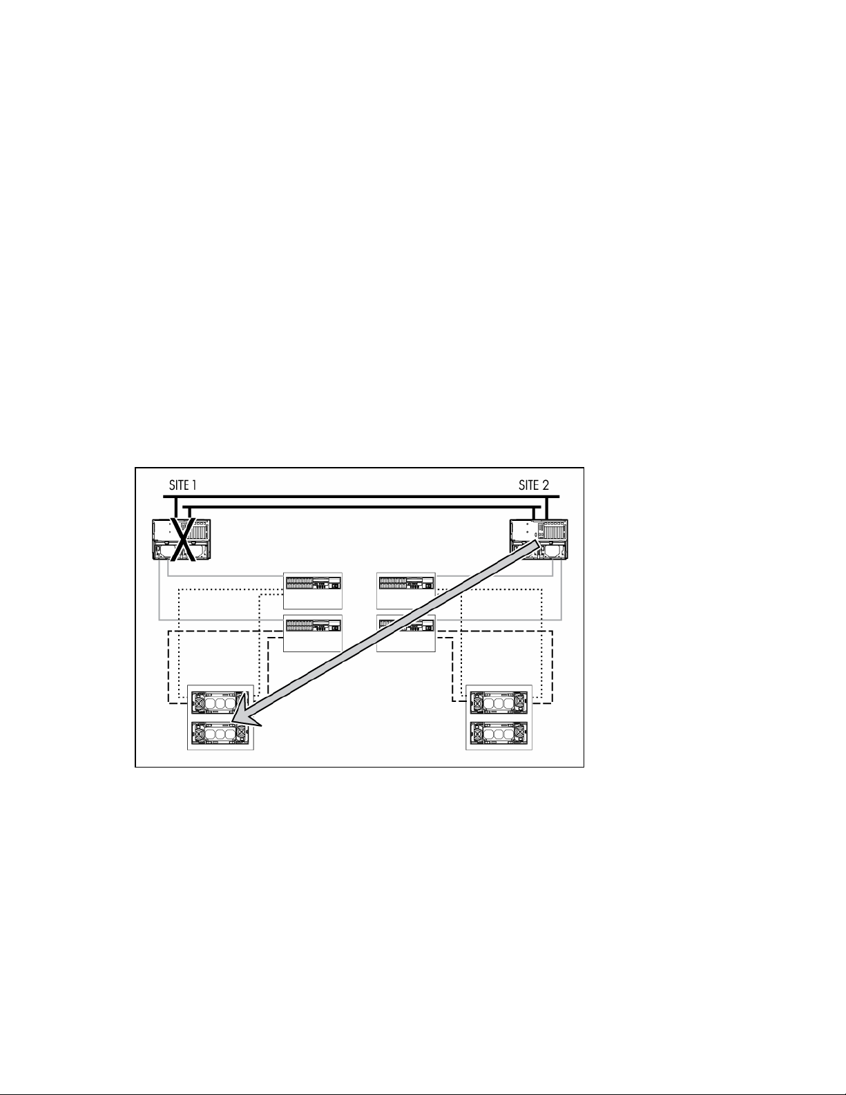
"Initiator Site Failback (on page 49)"
•
•
"Simple Failback Procedure for a Planned Failover (on page 49)"
•
"Full Failback Procedure for an Unplanned Failover (on page 49)"
Managing Data Replication Manager
Refer to the Data Replication Manager HSG80 ACS operations guide (referred to in this section as the
DRM guide) for complete instructions on managing the DRM.
F500 DT for MA8000 failure scenarios
The F500 DT for MA8000 cluster uses MSCS software to provide automated failover and failback of
MSCS resource failover and failback
applications, servers, and server resources. This provides an extra level of availability for applications.
A normal MSCS failover occurs if a cluster resource fails at the site. The exact failover behavior can be
configured for each cluster group, but usually this means that the entire cluster group containing the failed
resource might attempt to switch to the other cluster node. No storage subsystem failover is required in
this situation.
Use the standard failback mechanisms provided by MSCS to perform a failback after a resource failure.
There is no storage failback in this situation because no storage subsystem failover occurred.
Local server failure
A normal MSCS failover occurs if one of the cluster nodes fails. All of the resources defined in the cluster
groups that were running on the failed node will attempt to switch over to the surviving nodes. As with a
cluster resource failure, no storage subsystem failover is required. This is also the case when a cluster
node is brought down for a scheduled event, such as system maintenance.
Disaster recovery 47

Use the standard failback mechanisms provided by MSCS after the failed server has been repaired or
replaced. The server node automatically joins the cluster when the repaired server comes back online. The
failback of each cluster group is determined by the failback policy that has been defined in MSCS for that
group. Remove the failed server from the cluster before reinstalling the operating system if the server must
be replaced. Then install MSCS and join it to the existing cluster. Fail back to the other server to perform
a failback after a resource failure. There is no storage failback because there was no storage failover.
Initiator site failover
A small amount of downtime occurs during a site failover. The cluster does not have access to any data or
applications if the initiator storage system fails or is no longer available. The cluster is not available
during this time.
Refer to the DRM guide to determine the scenarios that warrant a failover.
There are two types of failover procedures to recover the remote copy sets: planned and unplanned. Use
the planned failover procedure when failover is a scheduled event; otherwise, use an unplanned failover
procedure.
Refer to the DRM guide for detailed instructions about both planned and unplanned failover procedures.
IMPORTANT: It is not necessary to reinstall the MSCS at the target site after a site failover is performed in
an F500 DT configuration. Do not reinstall MSCS.
Disaster recovery 48

The cluster nodes at the target site must be rebooted after you perform the site failover procedures.
Initiator site failback
When a new initiator site has been established or the original one restored, site operation can resume
after a failback procedure has been performed. A failback procedure involves synchronizing both the
initiator and target storage subsystems so that operation can be returned to the initiator with minimal
downtime. Verify that all components at both sites are operational before performing a failback.
The failback sequence is a scheduled event based on the configuration at the failback site. The storage
controller requires that a viable dual-redundant storage subsystem be available before a failback can take
place. Failback to a single controller configuration is not supported. A small amount of downtime is
required during the failback process.
IMPORTANT: The cluster is not available during initiator site failback. Consider this downtime when
scheduling a failback procedure.
Simple failback procedure for a planned failover
Use the simple failback procedure described in the DRM guide if the site failover is for a scheduled event.
The cluster nodes at both sites must be rebooted after you perform a simple failback procedure. The
cluster will start normally and applications and data accessed by means of MSCS will be available.
Full failback procedure for an unplanned failover
One of two procedures must be used for the site failback if the site failover is for an unplanned event. The
procedure that you use is determined by the state of the initiator site.
•
If the initiator site is intact, meaning that the servers and storage are still usable, perform the full
failback procedure described in the DRM guide.
The cluster nodes at both sites must be rebooted after you perform a full failback procedure. The
cluster will start normally, and applications and data accessed by means of MSCS will be available.
•
Perform the new hardware failback procedure described in the DRM guide if the initiator site is not
intact, that is, the servers and storage must be replaced.
IMPORTANT: MSCS must be reinstalled on the initiator site after a new hardware failback procedure is
performed for an unplanned failover in an F500 DT cluster. Do not reinstall MSCS on the target site.
Disaster recovery 49

The operating system and MSCS must be reinstalled on the server at the initiator site if a new hardware
failback procedure has been performed. Remove the failed server from the cluster before reinstalling the
operating system and MSCS and then join the existing cluster.
Disaster recovery 50

Zoning worksheets
In this section
Site A zoning worksheet.......................................................................................................................... 51
Site B zoning worksheet.......................................................................................................................... 51
Site A zoning worksheet
Locate and record the WWNs of each host on the zoning worksheet. Keep a copy of all worksheets at all
your sites.
Host WWN# Domain ID# Port # Alias name Site/location
Site B zoning worksheet
Locate and record the WWNs of each host on the zoning worksheet. Keep a copy of all worksheets at all
your sites.
Host WWN# Domain ID# Port # Alias name Site/location
Zoning worksheets 51

Host WWN# Domain ID# Port # Alias name Site/location
Zoning worksheets 52

Connection naming worksheet
In this section
Connection naming worksheet ................................................................................................................. 53
Connection naming worksheet
!NEWCONxx World wide name Host name Path Number
Connection naming worksheet 53

Technical support
In this section
Before you contact HP............................................................................................................................. 54
HP contact information............................................................................................................................ 54
Before you contact HP
Be sure to have the following information available before you call HP:
•
Technical support registration number (if applicable)
•
Product serial number
•
Product model name and number
•
Applicable error messages
•
Add-on boards or hardware
•
Third-party hardware or software
•
Operating system type and revision level
HP contact information
For the name of the nearest HP authorized reseller:
•
In the United States, see the HP US service locator webpage (http://www.hp.com/service_locator).
•
In other locations, see the Contact HP worldwide (in English) webpage
(http://welcome.hp.com/country/us/en/wwcontact.html
For HP technical support:
•
In the United States, for contact options see the Contact HP United States webpage
(http://welcome.hp.com/country/us/en/contact_us.html
•
Call 1-800-HP-INVENT (1-800-474-6836). This service is available 24 hours a day, 7 days a
week. For continuous quality improvement, calls may be recorded or monitored.
•
If you have purchased a Care Pack (service upgrade), call 1-800-633-3600. For more
information about Care Packs, refer to the HP website (http://www.hp.com
•
In other locations, see the Contact HP worldwide (in English) webpage
(http://welcome.hp.com/country/us/en/wwcontact.html
).
). To contact HP by phone:
).
).
Technical support 54

Acronyms and abbreviations
ACS
Array Controller Software (on page 58)
ATM
asynchronous transfer mode
CLI
Command Line Interface
DNS
domain name system
DR
Data Replication
DRM
Data Replication Manager
DT
disaster tolerant
EMU
environmental monitoring unit
EVA
Enterprise Virtual Array (on page 58)
FCA
Fibre Channel adapter
FCIP
Fibre Channel over Internet Protocol
FDDI
Fibre Data Distributed Interface
Acronyms and abbreviations 55

GBIC
Gigabit Interface Converter
HBA
host bus adapter (on page 58)
ISL
intersite link
LUN
logical unit number
MSCS
Microsoft® Cluster Server/Service
NIC
network interface controller
OCP
Operator Control Panel
OSG
Open Systems Gateway
PDU
power distribution unit
SAN
storage area network
SFP
small form-factor pluggable
SMA
Storage Management Appliance
SWCC
StorageWorks Command Console
VD
virtual disk
Acronyms and abbreviations 56

WWN
World Wide Name
Acronyms and abbreviations 57

Glossary
Array Controller Software
Software contained on a removable ROM program card that provides the operating system for the array
controller.
cluster
A group of systems that work collectively as a single system to provide fast, uninterrupted computing
service. Clustering is a way to increase availability, processing capacity, and I/O bandwidth.
Enterprise Virtual Array
The HP name used to describe the storage system that includes HSV controllers, storage devices,
enclosures, cables, and power supplies. Also known as the Enterprise Storage System.
failback (cluster)
1.
The process that takes place when a previously failed controller is repaired or replaced and
reassumes the workload from a companion controller.
2.
The process that takes place when the operation of a previously failed cluster group moves from one
cluster node back to its primary node.
failover (cluster)
1.
The process that takes place when one controller in a dual-redundant configuration assumes the
workload of a failed companion controller. Failover continues until the failed controller is repaired or
replaced.
2.
The process that takes place when the operation of a cluster group moves from one cluster node to
another node in the same cluster.
Fibre Channel
An IEEE standard for providing high-speed data transfer among workstations, servers, mainframes,
supercomputers, desktop computers, storage devices, and display devices.
Fibre Channel Adapter
An adapter used to connect the host server to the fabric.
high availability
A term used to identify a computer system that can continuously deliver services to its clients 99.9 % of the
time (no more than 8.5 hours of downtime per year).
host
The primary or controlling computer in a system of computers connected by communication links.
Glossary 58

host bus adapter
A card used to connect a peripheral device to a host server.
logical unit
Commonly called a LUN (which is the acronym for logical unit number). A physical or virtual device
addressable through a target ID number. Logical units use the target bus connection to communicate on
the SCSI bus. The host sees a virtual disk as a logical unit.
logical unit number
1.
A value that identifies a specific logical unit belonging to a SCSI target ID number. LUN is commonly
used in reference to a logical unit.
2.
A number associated with a physical device unit during the I/O operations of a task. Each task in
the system must establish its own correspondence between logical unit numbers and physical
devices.
maintenance terminal
An EIA-423-compatible terminal used with the controller. This terminal is used to identify the controller,
enable host paths, enter configuration information, and check the controller status.
Virtual Controller Software
Software used by the HSV controllers.
World Wide Name
World Wide Name. A unique Fibre Channel identifier consisting of a 16-character hexadecimal number.
A WWN is required for each Fibre Channel communication port.
Glossary 59

Index
A
association set, creating 36
Asynchronous Transfer Mode (ATM) connection 20
ATM (asynchronous transfer mode) connection 20
ATM link 30, 35
authorized reseller 54
B
basic configuration 6, 21
bidirectional configuration 7, 22, 40
bidirectional solution 13
C
cable, fiber optic 29
cabling, not supported 11
cabling, supported 11
CCL (Command Console LUN) 26, 31
clusters, adding 40
clusters, resource failover 42
Command Console LUN (CCL) 26, 31
commands, SHOW 39
configuration, basic 6, 21
configuration, bidirectional 7, 22, 40
configuration, DRM 25
configuration, hardware 9
configuration, initiator site 31, 34
configuration, maximum 8, 23
configuration, software 13
configuration, target site 26, 29
connection, ATM 20, 30
connection, controller to switch 29
connection, FCIP 5
connection, FDDI 5, 20
connection, fiber optic cable 29, 30
connection, host to switch 30
connection, non-ATM 20
connection, non-FCIP 5
connection, OSG (Open Systems Gateway) 30, 35
contact information 54
contacting HP 54
Continuous Access, managing 42
Continuous Access, restrictions 9
controller configuration 26, 31
controller to switch connections 29
copy sets, creating 18
customer self repair (CSR) 54
D
data replication (DR) groups, creating 18
Data Replication Manager (DRM) 24, 25
destination site 5
devices, discovering 18
disaster recovery 42
disaster tolerance, overview 5, 20
DR (data replication) groups, creating 18
DRM (Data Replication Manager) 24, 25
DRM (Data Replication Manager), managing 47
E
external fiber link 29, 35
F
F500 DT for EVA, disaster recovery 42
F500 DT for MA8000, disaster recovery 46
F500 DT, overview 5, 20
failback 58
failback, initiator site 49
failback, ISL 46
failback, source site 45
failback, storage 45
failover 58
failover, initiator site 48
failover, MSCS resource 43, 47
failover, planned 49
failover, source site 44
failover, unplanned 49
failure, local server 43
failure, MSCS resource 43
FCIP (Fibre Channel over Internet Protocol)
connection 5
FDDI (Fibre Data Distributed Interface) connection 5,
20
fiber optic cables 29, 30
Index 60

Fibre Channel over Internet Protocol (FCIP)
connection 5
Fibre Channel switch, basic configuration 6, 21
Fibre Channel switch, overview 5
Fibre Channel switch, setup 25
Fibre Data Distributed Interface (FDDI) connection 5,
20
full failback 49
H
HBA, installation 30
help resources 54
host connections 31
host server, initiator access 38
host to switch connections 30
host, adding 17
host, creating folder 17
HP Technical Support 54
I
initiator site 20
initiator site failback 49
initiator site failover 48
initiator site, adding clusters 41
initiator site, ATM link 35
initiator site, connecting cables 29, 30
initiator site, controller configuration 31
initiator site, fiber link 35
initiator site, host access 38
initiator site, host configuration 37, 41
initiator site, host connections 38
initiator site, remote copy sets 35
initiator site, storage configuration 34
installation, server options 41
installing MSCS 39
installing SWCC (StorageWorks Command
Console) 30
intersite link (ISL) failback 46
ISL (intersite link) failback 46
L
license key 15
link, network 5
link, storage 5
local site, known as 5, 20
log unit, assigning 36
log unit, creating 36
M
maintenance terminal 25
managed sets, creating 19
Microsoft Cluster Server/Service (MSCS) 56
mirrorset 36
MSCS failover 43, 47
MSCS installation 39
N
network interface controller (NIC) 56
network link 5
non-ATM connection 20
non-FCIP connection 5
O
Open Systems Gateway (OSG) connection 30, 35
OSG (Open Systems Gateway) connection 30, 35
P
phone numbers 54
R
remote copy sets, creating 35
remote site, known as 5, 20
required information 54
resource failover 42
S
Secure Path Manager 38
server options, installing 41
server, designating maintenance terminal 25
SHOW commands 39
simple failback 49
SMA (SAN Management Appliance), logging
on 14
source site 5
source site failback 45
source site failover 44
source site, initializing 15
source site, naming 15
storage configuration 29, 34
storage controller configuration 26, 31
storage link 5
storage, bidirectional configuration 40
StorageWorks Command Console (SWCC),
installing 30
support 54
Index 61

SWCC (StorageWorks Command Console),
installing 30
T
target site 20
target site, adding clusters 41
target site, ATM link 30
target site, connecting cables 29
target site, controller configuration 26
target site, fiber link 29
target site, host configuration 30, 41
target site, host connections 31
target site, remote copy sets 35
target site, storage configuration 29
technical support 54
telephone numbers 54
terminal emulator session 39
V
Virtual Disks (VD), creating VD folders 16
Virtual Disks (VD), creating VDs 16
Virtual Disks (VD), presenting to host 17
W
World Wide Name (WWN) location 10, 25
WWN (World Wide Name) location 10, 25
Index 62
 Loading...