

Page 1

HP ProLiant Cluster F500 Installation Guide
September 2006 (Second Edition)
Part Number 364775-002
Page 2

© Copyright 2004, 2006 Hewlett-Packard Development Company, L.P.
The information contained herein is subject to change without notice. The only warranties for HP products and services are set forth in the express
warranty statements accompanying such products and services. Nothing herein should be construed as constituting an additional warranty. HP
shall not be liable for technical or editorial errors or omissions contained herein.
Microsoft, Windows, and Windows NT are U.S. registered trademarks of Microsoft Corporation. Windows Server 2003 is a trademark of
Microsoft Corporation. Intel, Pentium, and Itanium are trademarks or registered trademarks of Intel Corporation or its subsidiaries in the United
States and other countries. UNIX is a registered trademark of The Open Group.
September 2006 (Second Edition)
Part Number 364775-002
Audience assumptions
This document is for the person who installs, administers, and troubleshoots servers and storage systems.
HP assumes you are qualified in the servicing of computer equipment and trained in recognizing hazards
in products with hazardous energy levels.
Page 3

Contents
Overview of the ProLiant Cluster F500 ............................................................................................ 5
HP ProLiant Cluster F500 overview .............................................................................................................. 5
Hardware and software components ........................................................................................................... 5
F500 for EVA configurations....................................................................................................................... 5
Cluster cross-cable configuration ....................................................................................................... 6
F500 for MA8000 configurations ............................................................................................................... 6
Enhanced configuration.................................................................................................................... 7
Multiple cluster configurations ........................................................................................................... 8
HP OpenView Storage Management Appliance............................................................................................ 8
Cluster interconnect ................................................................................................................................... 8
Redundant interconnects............................................................................................................................. 9
Interconnect adapters................................................................................................................................. 9
Client network........................................................................................................................................... 9
Ethernet direct connection......................................................................................................................... 10
Cluster networking................................................................................................................................... 10
Setting up the ProLiant Cluster F500 for Enterprise Virtual Array....................................................... 11
Preinstallation instructions ......................................................................................................................... 11
Hardware setup and configuration ............................................................................................................11
Setting Up the HP StorageWorks Enterprise Virtual Array ................................................................... 12
Setting Up the HP OpenView storage management appliance............................................................. 12
Setting up the HP ProLiant servers .................................................................................................... 12
Updating the FCA device driver ...................................................................................................... 13
Setting IP addressing and zoning for Fibre Channel switches .............................................................. 13
Creating zones ............................................................................................................................. 14
Downloading the latest FCA driver .................................................................................................. 15
Installing HP StorageWorks Secure Path ........................................................................................... 15
Logging on to the storage system..................................................................................................... 16
Creating the storage system and virtual disks ....................................................................................16
Configuring virtual disks on the host................................................................................................. 17
Installing clustering ........................................................................................................................17
Setting up the ProLiant Cluster F500 for MA8000........................................................................... 19
Preinstallation instructions ......................................................................................................................... 19
Hardware setup and configuration ............................................................................................................19
Setting Up the HP StorageWorks MA8000.......................................................................................20
Setting Up the HP OpenView storage management appliance............................................................. 20
Setting up the HP ProLiant servers .................................................................................................... 20
Installing the HBA device driver....................................................................................................... 21
Downloading the latest HBA driver ..................................................................................................21
Installing HP StorageWorks Secure Path ........................................................................................... 21
Setting IP addressing and zoning for Fibre Channel switches .............................................................. 22
Creating zones ............................................................................................................................. 22
Designating the server as a maintenance terminal.............................................................................. 22
Turning on the storage subsystem power........................................................................................... 23
Configuring the storage subsystem................................................................................................... 23
Logging on to the storage system..................................................................................................... 24
Discovering the storage system and identifying the connections ........................................................... 24
Creating and presenting the virtual disks ..........................................................................................24
Configuring virtual disks on the host................................................................................................. 25
Contents 3
Page 4

Configuring large LUNs (optional) ...................................................................................................25
Installing clustering ........................................................................................................................25
Connection worksheet ................................................................................................................. 26
Connection worksheet.............................................................................................................................. 26
Technical support........................................................................................................................ 27
Before you contact HP.............................................................................................................................. 27
HP contact information............................................................................................................................. 27
Acronyms and abbreviations........................................................................................................ 28
Glossary.................................................................................................................................... 30
Index......................................................................................................................................... 35
Contents 4
Page 5

Overview of the ProLiant Cluster F500
In this section
HP ProLiant Cluster F500 overview............................................................................................................. 5
Hardware and software components .......................................................................................................... 5
F500 for EVA configurations ..................................................................................................................... 5
F500 for MA8000 configurations .............................................................................................................. 6
HP OpenView Storage Management Appliance .......................................................................................... 8
Cluster interconnect .................................................................................................................................. 8
Redundant interconnects ........................................................................................................................... 9
Interconnect adapters ............................................................................................................................... 9
Client network.......................................................................................................................................... 9
Ethernet direct connection ....................................................................................................................... 10
Cluster networking.................................................................................................................................. 10
HP ProLiant Cluster F500 overview
The HP ProLiant Cluster F500 for Enterprise Virtual Array is a two-to-eight-node cluster solution (eight-node
clustering is supported by Microsoft® Windows® Server 2003, Enterprise Edition) composed of HP
ProLiant servers and the HP StorageWorks EVA storage system.
The HP ProLiant Cluster F500 for MA8000 is a two-node cluster solution composed of HP ProLiant servers
and HP StorageWorks storage components. These cluster solutions execute on a Microsoft® Windows®
Server 2003, Enterprise Edition platform or a Microsoft® Windows® 2000 Advanced Server platform
with Microsoft® Cluster Service (two-node).
Hardware and software components
For a current list of supported hardware and software components, refer to the High Availability website
(http://www.hp.com/servers/proliant/highavailability
).
F500 for EVA configurations
The HP ProLiant Cluster F500 for EVA is a cluster with two Fibre Channel Adapters in each server, two
switches, and two storage controllers. In an F500 configuration, each storage controller pair can be
attached to a maximum of 240 drives.
Overview of the ProLiant Cluster F500 5
Page 6
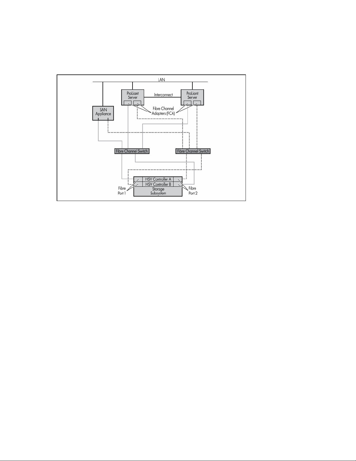
Cluster cross-cable configuration
A cluster cross-cable configuration has no single point of failure. To enable dual paths to the storage, the
HP StorageWorks Secure Path software must be installed on all servers. With Secure Path, data can flow
simultaneously over both FCAs to the storage subsystem, and you can perform load balancing over the
two paths to help maximize performance.
A component failure in this cluster results in a failover to a second component, and you can continue
using the cluster. Some typical failures and responses in the enhanced configuration include:
•
A server failure causes Microsoft® cluster software to fail over to the other node.
•
An HBA or FCA failure causes subsequent data requests intended for the failed adapter to be routed
over the remaining good adapter.
•
A switch or cable failure is detected as an HBA or FCA failure, and a failover to the second adapter,
which is using the remaining good switch and good cables, occurs.
•
A controller failure causes the second controller to take over for the failed controller. Secure Path
then routes the data requests to the second controller.
In all of the typical failures, interruptions to the user are minimal and, in some cases, might not even be
noticeable.
F500 for MA8000 configurations
The HP ProLiant Cluster F500 for MA8000 configurations support Fibre Channel switches with the Array
Controller Software and disaster-tolerant configurations.
The F500 can be set up in several different configurations, involving servers, switches, and storage
subsystems connected through a Fibre Channel Switched Fabric:
•
The enhanced configuration is a cluster with two HBAs in each server, two switches, and two storage
controllers, giving it increased availability over the basic configurations.
•
Additionally, two to four clusters can be configured to use the same storage subsystems.
In an F500 configuration, a maximum of four storage controller pairs can be connected to a single
cluster. This limitation dictates how many storage subsystems can be used in the cluster (a maximum of
four storage subsystems or some combination of each type of storage unit).
Overview of the ProLiant Cluster F500 6
Page 7
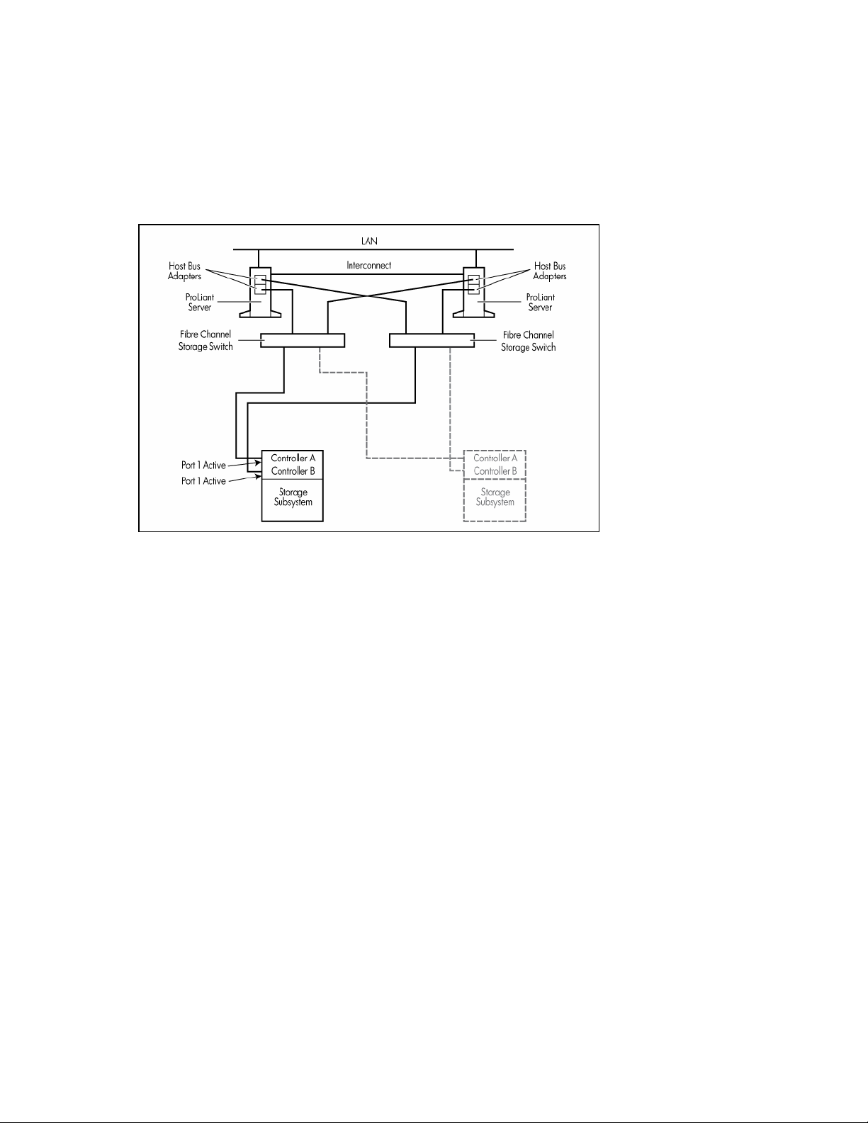
Enhanced configuration
No single points of failure occur in an enhanced configuration. It improves on the basic configuration by
adding a second HBA to each server and a second switch. The combination of second adapter, switch,
and controller form a second independent path to the storage subsystem.
To enable dual paths to the storage, the Secure Path software must be installed on all servers. With
Secure Path, data can flow simultaneously over both HBAs to the storage subsystem, and you can perform
load balancing over the two paths to help maximize performance.
A component failure in this cluster results in a failover to a second component, and you can continue
using the cluster. Some typical failures and responses in the enhanced configuration include:
•
A server failure causes Microsoft® cluster software to fail over to the other node.
•
An HBA or FCA failure causes subsequent data requests intended for the failed adapter to be routed
over the remaining good adapter.
•
A switch or cable failure is detected as an HBA or FCA failure, and a failover to the second adapter,
which is using the remaining good switch and good cables, occurs.
•
A controller failure causes the second controller to take over for the failed controller. Secure Path
then routes the data requests to the second controller.
In all of the typical failures, interruptions to the user are minimal and, in some cases, might not even be
noticeable.
Overview of the ProLiant Cluster F500 7
Page 8
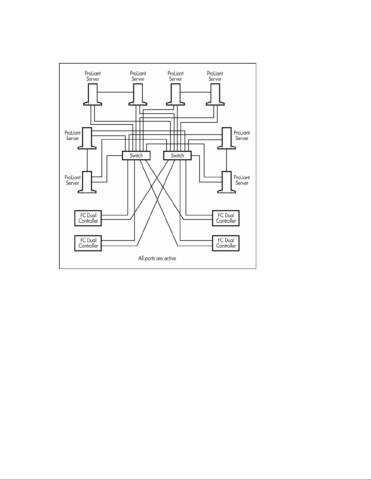
Multiple cluster configurations
Up to four clusters can be combined into a single F500 for MA8000 configuration with the clusters
accessing the same group of storage subsystems.
HP OpenView Storage Management Appliance
The HP OpenView Storage Management Appliance runs the HP StorageWorks Command View EVA
software and the HSG Element Manager software. The Command View EVA software is the
administrative interface to the EVA, and the HSG Element Manager software is the administrative
interface to the MA8000. The application is browser-based and can be used from any machine on the
same IP network as the management appliance.
Cluster interconnect
The cluster interconnect is a data path over which nodes of a cluster communicate. This type of
communication is termed intracluster communication. At a minimum, the interconnect consists of two
network adapters (one in each server) and a crossover cable connecting the adapters.
The cluster nodes use the interconnect data path to:
•
Communicate individual resource and overall cluster status
•
Send and receive heartbeat signals
•
Update modified registry information
Overview of the ProLiant Cluster F500 8
Page 9

IMPORTANT: TCP/IP must be used as the cluster communication protocol. When configuring the
interconnects, be sure to enable TCP/IP.
Redundant interconnects
To reduce potential disruptions of intracluster communication, use a redundant path over which
communication can continue if the primary path is disrupted.
HP recommends configuring the client LAN as a backup path for intracluster communication. This provides
a secondary path for the cluster heartbeat in case the dedicated primary path for intracluster
communications fails. This is configured when installing the cluster software, or it can be added later
using the MSCS Cluster Administrator.
HP offers a feature that configures two HP Ethernet adapters (or two ports on a single adapter) so that one
is a hot backup for the other. There are two ways to achieve this configuration, called NIC Teaming, and
the method you choose depends on the hardware. One way is through the use of the Redundant NIC
Utility available on all HP 10/100/1000 Fast Ethernet products. The other option is through the use of
the Network Fault Tolerance feature designed to operate with the HP 10/100/1000 Intel® silicon-based
NICs.
For more information on recommended interconnect strategies, refer to the white paper, Best Practices
Checklist—Increasing Network Fault Tolerance in a Microsoft® Windows® Server 2003, Enterprise
Edition High Availability Server Cluster, available from the ProLiant High Availability website
(http://www.hp.com/servers/proliant/highavailability
).
NOTE: Only use NIC Teaming with NICs that connect to the client LAN. Do not use this feature with NICs
used for the dedicated intracluster communication link. For detailed information about interconnect
redundancy, refer to the HP white paper, Increasing Network Availability in a Microsoft® Windows®
Cluster, available from the High Availability website
(http://www.hp.com/servers/proliant/highavailability
).
Interconnect adapters
Ethernet adapters and switches are supported as interconnects in ProLiant clusters. Either a 10-Mb/s, 100Mb/s, or 1000-Mb/s Ethernet adapter can be used.
NOTE: For a list of supported interconnect adapters, refer to the Microsoft® Windows® Server 2003,
Enterprise Edition, Windows® 2000 Advanced Server, and Microsoft® cluster software compatibility list
available from the Microsoft® website (http://www.microsoft.com
). Be sure that the adapter you select is on
the list.
NOTE: An Ethernet crossover cable is provided in the HP ProLiant Cluster F500 for the Enterprise SAN kit.
The crossover cable is for a two-node configuration only.
Client network
Every client/server application requires a LAN over which client machines and servers communicate. The
components of the LAN are no different than with a stand-alone server configuration.
Because clients desiring the full advantage of the cluster will now connect to the cluster rather than to a
specific server, configuring client connections will differ from those for a stand-alone server. Clients will
connect to virtual servers, which are cluster groups that contain their own IP addresses.
Overview of the ProLiant Cluster F500 9
Page 10

Ethernet direct connection
A direct Ethernet connection uses only three components:
•
Two interconnect adapters
•
One Ethernet crossover cable
Connecting interconnect adapters directly to each other requires a special cable. If you are using
Ethernet, an Ethernet crossover cable (included in the HP ProLiant Cluster F500 for the Enterprise SAN kit)
must be used.
If you are using the Ethernet crossover cable supplied with your kit and installing Windows® 2000
Advanced Server, the interconnect network might not display during the cluster installation because the
connection displays only if it is currently active at the time of installation. If the other cluster nodes are
powered off at the time you install MSCS, the connection is considered inactive by Windows® Server
2003, Enterprise Edition and Windows® 2000 Advanced Server. In this case, define the existing public
network connection as all communications during the installation. After MSCS is configured on all
nodes, the interconnect network automatically shows in the networks group in Cluster Administrator.
To configure the networks for MSCS use after installing Windows® Server 2003, Enterprise Edition or
Windows® 2000 Advanced Server:
1.
Right-click the cluster name in Cluster Administrator.
2.
Select Properties.
3.
Select the Network Priority tab from the dialog box.
4.
Configure the network roles as necessary.
Cluster networking
For troubleshooting information on this topic, refer to the following Microsoft® articles and related
documentation on the Microsoft® website (http://www.microsoft.com/support
•
Q193890—Recommended WINS Configuration for Microsoft Cluster Server
•
Q254101—Network Adapter Teaming and Server Cluster
•
Q254651—Cluster Network Role Changes Automatically
•
Q258750—Recommended Private "Heartbeat" Configuration on a Cluster Server
).
Overview of the ProLiant Cluster F500 10
Page 11

Setting up the ProLiant Cluster F500 for
Enterprise Virtual Array
In this section
Preinstallation instructions........................................................................................................................ 11
Hardware setup and configuration ........................................................................................................... 11
Preinstallation instructions
Before setting up the F500, verify that the hardware and software kits are appropriate for this installation.
For a current list of supported hardware and software components, refer to the High Availability website
(http://www.hp.com/servers/proliant/highavailability
).
Hardware setup and configuration
Verify that you have all the necessary hardware (minimum setup):
•
Two ProLiant servers
•
Two FCA cards for each server
•
Two NIC cards for each server
•
One EVA storage system
•
Two Fibre Channel switches
•
One HP OpenView Storage Management Appliance
Verify that you have all the necessary software:
•
Command View EVA
•
SmartStart CD
•
Microsoft® Windows® Server 2003, Enterprise Edition or Microsoft® Windows® 2000 Advanced
Server
•
CD that came with the EVA platform kit
•
HP StorageWorks Secure Path software
Set up the cluster using the following procedures:
1.
"Setting up the HP StorageWorks Enterprise Virtual Array (on page 12)"
2.
"Setting up the HP OpenView storage management appliance (on page 12)"
3.
"Setting up the HP ProLiant servers (on page 12)"
4.
"Updating the FCA device driver (on page 13)"
5.
"Setting IP addressing and zoning for Fibre Channel switches (on page 13)"
6.
"Creating zones (on page 14)"
7.
"Creating storage aliases (on page 14)"
Setting up the ProLiant Cluster F500 for Enterprise Virtual Array 11
Page 12

"Downloading the latest FCA driver (on page 15)"
8.
9.
"Installing HP StorageWorks Secure Path (on page 15)"
10.
"Logging on to the storage system (on page 16)"
11.
"Creating the storage system and virtual disks (on page 16)"
12.
"Configuring virtual disks on the host (on page 17)"
13.
"Installing clustering (on page 17)"
Setting Up the HP StorageWorks Enterprise Virtual Array
Install the following:
•
Rack, drive enclosures, disk drives, and associated firmware
•
Environmental Monitoring Unit
•
HSV controllers
Refer to the EVA hardware documentation for detailed installation and setup instructions.
Setting Up the HP OpenView storage management appliance
1.
Set up the management appliance.
2.
Install the Command View EVA software.
Refer to the management appliance documentation for detailed setup and configuration instructions.
Setting up the HP ProLiant servers
1.
Install the following hardware in the servers:
a.
FCAs
The FCA board plugs into a standard PCI slot in the host computer. Refer to the system manual for
instructions on plugging in boards.
IMPORTANT: Record the FCA/HBA ID (12-digit IEEE address) and the server and adapter slot in which
the adapter is installed. You will need this information when configuring switch zoning and creating the
storage system and virtual disks. Use the Connection Worksheet (on page 26) to record the information.
b.
NICs
2.
Cable the fiber connections to the servers, storage, and management appliance.
3.
Set up and cable the Ethernet network.
IMPORTANT: You must have a working network to configure the storage with the management appliance.
4.
Configure the servers using the SmartStart CD or Deployment Server.
5.
Install one of the following operating systems:
NOTE: For supported operating system versions, refer to the HP website
(http://www.hp.com/servers/proliant/highavailability
a.
Microsoft® Windows® Server 2003, Enterprise Edition
b.
Windows® 2000 Advanced Server
6.
Verify that all the latest drivers and agents are loaded using the SmartStart CD.
7.
Configure the public and private network cards.
).
NOTE: Refer to the Microsoft® Q articles ("Cluster networking" on page 10) on networking for detailed
information.
Setting up the ProLiant Cluster F500 for Enterprise Virtual Array 12
Page 13

Log on to the network domain controller.
8.
Refer to your server documentation and FCA documentation for detailed installation instructions.
Updating the FCA device driver
This procedure updates Windows® Server 2003 or Windows® 2000 Advanced Server to the EVAsupported FCA driver version.
1.
Insert the CD that came with the Enterprise kit into the server CD-ROM drive. If autorun is enabled,
the installation program starts. Otherwise, navigate to the root directory of the CD, and double-click
install.bat.
2.
Click Install Solution Software.
3.
Click Perform Fibre Channel Adapter Driver Update to start the Driver Update Utility.
When the driver installation finishes, a menu displays for additional software installation.
4.
Click Install Fibre Channel Software to start the Fibre Channel setup wizard for the additional
software installation.
5.
Click Finish to restart the server when the setup wizard completes.
6.
Repeat steps 1 through 5 for additional cluster nodes.
Setting IP addressing and zoning for Fibre Channel switches
Set IP addressing and zoning to meet your SAN requirements. Refer to the HP StorageWorks Fibre
Channel SAN Switch Management Guide for detailed instructions.
The IP address setting procedures must be performed on every switch in the fabric.
Setting the Switch: 8, 16, 32 port
1.
Connect a terminal or terminal emulator to the serial port of the switch.
2.
Set the IP address.
3.
Verify that the switch firmware level meets the storage system requirements. Refer to the
Heterogeneous Open SAN Design Reference Guide.
4.
Use a Web browser to monitor and manage the switch.
Verifying FCA firmware
Verify that the FCA cards have the correct firmware. For a list of current firmware, refer to the HP website
(http://www.hp.com/servers/proliant/highavailability
).
Setting up the ProLiant Cluster F500 for Enterprise Virtual Array 13
Page 14

Creating zones
The following figure is an example of a cluster cross-cable zoning configuration setup.
To create a controller zone, cluster zones, and a configuration zone, use the SAN switch GUI. Refer to
the switch documentation for detailed information on using the GUI for setting up zones.
Creating storage aliases
To avoid a storage system being zoned out of the fabrics if the designations for Controllers A and B
become reversed, HP recommends that you zone using the host WWN address for each fabric instead of
the controller host port World Wide IDs.
Setting up the ProLiant Cluster F500 for Enterprise Virtual Array 14
Page 15

In the example shown, the storage system host WWN is designated as 50:00:1f:e1:50:00:cb:80.
Cabled to this fabric are Controller A, port 2 (50:00:1f:e1:50:00:cb:89) and Controller B, port 1
(50:00:1f:e1:50:00:cb:8c). The storage system host WWN is highlighted, and the ADD FA Host> button
is used to place the storage system into the fabric.
The port WWIDs associated with the storage system WWN in each fabric would reverse if the Controller
A and Controller B designations become reversed. Using host zoning, the switch uses any port WWID
associated with the host WWN even if the port WWIDs change.
Downloading the latest FCA driver
1.
Verify the FCA driver version installed on your system.
2.
Go to the HP website (http://www.hp.com/servers/proliant/highavailability), select Cluster
configuration support matrices, and check for the latest Fibre Channel Host Bus Adapter
driver version supported.
IMPORTANT: Omit the following step if you have the latest FCA driver installed on your system.
3.
Download the latest FCA driver update utility, and install the update utility on each server, one server
at a time.
Installing HP StorageWorks Secure Path
Secure Path must be installed before any virtual disks can be recognized and configured. Follow the
instructions that come with Secure Path for more specific installation and configuration information.
1.
Install Secure Path using the latest kit. Follow the on-screen instructions. Configure the host in Secure
Path to reflect the server and the monitor node.
IMPORTANT: Verify that reverse look-up is configured on the DNS server if you are using the FQDN.
2.
Restart the servers.
Setting up the ProLiant Cluster F500 for Enterprise Virtual Array 15
Page 16

Select Computer Management (Local)>Device Manager, and under Disk drives, verify that
3.
all the drives were discovered.
Logging on to the storage system
Use a supported Web browser to access the management appliance. A list of supported browsers is
available in the documentation that comes with the Command View EVA software.
Refer to the EVA documentation for instructions on opening the Command View EVA.
1.
Log in to the management appliance from any network browser.
2.
Select Devices>Command View EVA to launch the Command View EVA.
Creating the storage system and virtual disks
To begin the configuration process, create or initialize the storage system. When you first view the EVA
from the Command View EVA software, the storage pool is presented as "uninitialized storage."
Before the host servers can use the virtual disks, you must:
•
Initialize the storage system.
•
Add hosts to the storage system.
•
Create and present virtual disks to hosts.
Refer to the online help within the Command View EVA for information on these procedures. All of these
procedures must be completed for the hosts to use the virtual disks.
1.
Initialize the storage with a descriptive name. Decide how to configure the disk groups during the
initialization process. Choose to create either multiple disk groups or a single disk group.
2.
Enter a license key if the management appliance requests one.
3.
Configure the disk groups.
4.
Set the storage system time.
5.
Add the hosts to the storage system:
a.
Select Hosts.
b.
Click Add a Host.
c.
Enter a host name.
d.
Enter the correct IP address.
IMPORTANT: If the wrong IP address is entered and saved at the end of this procedure, it cannot be
changed without deleting and recreating the host.
e.
Click Next Step.
f.
Enter an adapter port WWN. Use the Connection Worksheet (on page 26) to correctly identify
which FCA card is located in each server. Select the correct WWN from the list.
g.
Select Microsoft® Windows® as the operating system.
h.
Click Next Step.
i.
Select Finish>OK.
j.
Click Add a Port.
k.
Select the second FCA from the list.
l.
Select Finish>OK.
m.
Repeat steps a through l for the next host.
6.
Create the virtual disk drives:
Setting up the ProLiant Cluster F500 for Enterprise Virtual Array 16
Page 17

Click Virtual Disks.
a.
b.
Click Create VD Fam.
c.
Assign the virtual disk name.
d.
Select a Vraid.
e.
Select the correct Prefer path/mode. Path A-Failover only or Path B-Failover only are the
only options supported for clustering.
f.
Select Finish>OK.
g.
Repeat steps a through f to create the virtual disks needed based on the number of logical units
you will have.
7.
Present the virtual disk drives to all hosts in the cluster:
a.
Select a physical disk.
b.
Click Present.
c.
Select a host.
d.
Select Finish>OK.
e.
Click Present.
f.
Select the next host.
g.
Select Finish>OK.
h.
Verify that the presented hosts are on the same logical unit number.
i.
Select another physical disk, and repeat steps a through h until all virtual disks in the cluster are
presented to the hosts.
Configuring virtual disks on the host
After you have set up the virtual disks on the EVA and rescanned or restarted the host, follow the hostspecific conventions for configuring these new disk resources. These new virtual disk resources then
become usable to the host system just like any other disk or device resource.
Windows® Server 2003, Enterprise Edition and Windows® 2000 Advanced Server require that disks be
partitioned, formatted, and assigned drive letters. Windows® 2000 Advanced Server also requires
selecting the disk type (select Basic only). Use the Disk Management utility within the Computer
Management application to configure the virtual disks using standard Windows® 2000 conventions.
1.
Power down all servers, except one.
2.
Use Disk Management or Disk Administrator to configure the newly discovered drives:
•
Select the disk type (Basic only).
•
Partition the disks.
•
Perform an NTFS format on each disk.
•
Assign disk drive letters. Drive letters typically run from E to Z. Label the drive volumes as, for
example, Drive E, Drive F, or Drive Z for easy identification.
Installing clustering
1.
Shut down all of the nodes, except one.
2.
Install clustering on the first node.
3.
Reboot the first node.
4.
Power up the next server. Allow enough time for the server to discover the paths and LUNs presented
to the cluster.
5.
Install clustering on the second node, and have it join the existing cluster.
Setting up the ProLiant Cluster F500 for Enterprise Virtual Array 17
Page 18

Reboot the second node.
6.
7.
If you want additional nodes to join the cluster, power them up individually and allow them enough
time to discover the paths and LUNs presented to the cluster.
8.
Install your applications.
9.
Repeat steps 1 through 8 for each cluster.
Setting up the ProLiant Cluster F500 for Enterprise Virtual Array 18
Page 19

Setting up the ProLiant Cluster F500 for MA8000
In this section
Preinstallation instructions........................................................................................................................ 19
Hardware setup and configuration ........................................................................................................... 19
Preinstallation instructions
Before setting up the F500, verify that the hardware and software kits are appropriate for this installation.
For a current list of supported hardware and software components, refer to the High Availability website
(http://www.hp.com/servers/proliant/highavailability
).
Hardware setup and configuration
Verify that you have all the necessary hardware (minimum setup):
•
Two ProLiant servers
•
Two HBA cards for each server
•
Two NIC cards for each server
•
One MA8000 storage system
•
Two Fibre Channel switches
•
One HP OpenView Storage Management Appliance
Verify that you have all the necessary software:
•
HSG Element Manager
•
SmartStart CD
•
Microsoft® Windows® Server 2003, Enterprise Edition or Microsoft® Windows® 2000 Advanced
Server
•
HP StorageWorks Secure Path software
Set up the cluster using the following procedures:
1.
"Setting up the HP StorageWorks MA8000 (on page 20)"
2.
"Setting up the HP OpenView storage management appliance (on page 20)"
3.
"Setting Up the HP ProLiant servers (on page 20)"
4.
"Installing the HBA device driver (on page 21)"
5.
"Downloading the latest HBA driver (on page 21)"
6.
"Installing HP StorageWorks Secure Path (on page 15)"
7.
"Setting IP addressing and zoning for Fibre Channel Switches (on page 13)"
8.
"Creating zones (on page 22)"
Setting up the ProLiant Cluster F500 for MA8000 19
Page 20

"Designating the server as a maintenance terminal (on page 22)"
9.
10.
"Turning on the storage subsystem power (on page 23)"
11.
"Configuring the storage subsystem (on page 23)"
12.
"Logging On to the Storage Subsystem ("Logging on to the storage system" on page 24)"
13.
"Discovering the Storage System and Identifying the Connections (on page 24)"
14.
"Creating and Presenting the Virtual Disks (on page 24)"
15.
"Configuring Virtual Disks on the Host (on page 25)"
16.
"Installing clustering (on page 25)"
Setting Up the HP StorageWorks MA8000
Install the following:
•
Rack, drive enclosures, disk drives, and associated firmware
•
HSG controllers
Refer to the documentation that was shipped with the storage subsystem for detailed installation
instructions.
Setting Up the HP OpenView storage management appliance
1.
Set up the management appliance.
2.
Install the HSG Element Manager software.
Refer to the management appliance documentation for detailed setup and configuration instructions.
Setting up the HP ProLiant servers
1.
Install the following hardware in the servers:
a.
HBAs
The HBA board plugs into a standard PCI slot in the host computer. Refer to the system manual for
instructions on plugging in boards.
IMPORTANT: Record the FCA/HBA ID (12-digit IEEE address) and the server and adapter slot in which
the adapter is installed. You will need this information when configuring switch zoning and creating the
storage system and virtual disks. Use the Connection Worksheet (on page 26) to record the information.
b.
NICs
2.
Cable the fiber connections to the servers, storage, and the management appliance.
3.
Set up and cable the Ethernet network.
IMPORTANT: You must have a working network to configure the storage with the
management appliance.
4.
Configure the servers using the SmartStart CD or Deployment Server.
5.
Install one of the following operating systems:
NOTE: For supported operating system versions, refer to the HP website
(http://www.hp.com/servers/proliant/highavailability
a.
Microsoft® Windows® Server 2003, Enterprise Edition
b.
Windows® 2000 Advanced Server
6.
Verify that all the latest drivers and agents are loaded using the SmartStart CD.
7.
Configure the public and private network cards.
).
Setting up the ProLiant Cluster F500 for MA8000 20
Page 21

NOTE: Refer to the Microsoft® Q articles ("Cluster networking" on page 10) on networking for detailed
information.
8.
Log on to the network domain controller.
Refer to your server documentation and HBA documentation for detailed installation instructions.
Installing the HBA device driver
This procedure installs the Windows® Server 2003, Enterprise Edition or Windows® 2000 Advanced
Server to the MA8000-supported HBA driver version.
1.
Insert the CD that came with the MA8000 kit into the server CD-ROM drive. If autorun is enabled,
the installation program starts. Otherwise, navigate to the root directory of the CD and double-click
launch.exe.
2.
Click Solution Software for Windows.
3.
Click Perform Multiple Driver Update to start the Driver Update Utility.
When the driver installation finishes, a menu displays for additional software installation.
4.
Click Fibre Channel Software Setup to start the Fibre Channel setup wizard for the additional
software installation.
5.
Click Finish to restart the server when the setup wizard completes.
6.
Repeat steps 1 through 5 for the second server.
Downloading the latest HBA driver
1.
Verify the HBA driver version installed on your system.
2.
Go to the HP website (http://www.hp.com/servers/proliant/highavailability), click Cluster
configuration support matrices, and check for the latest Fibre Channel Host Bus Adapter
driver version supported.
IMPORTANT: Omit the following step if you have the latest Fibre Channel HBA driver installed on the
server.
3.
Download the latest HBA driver update utility, and install the update utility on each server, one
server at a time.
Verifying HBA firmware
Verify that the HBA cards have the correct firmware. For a list of current firmware, refer to the HP website
(http://www.hp.com/servers/proliant/highavailability
).
Installing HP StorageWorks Secure Path
Secure Path must be installed before any virtual disks can be recognized and configured. Follow the
instructions that come with Secure Path for more specific installation and configuration information.
1.
Install Secure Path using the latest kit. Follow the on-screen instructions. Configure the host in Secure
Path to reflect the server and the monitor node.
IMPORTANT: Verify that reverse look-up is configured on the DNS server if you are using the FQDN.
2.
Restart the servers.
3.
Select Computer Management (Local)>Device Manager, and under Disk drives, verify that
all the drives were discovered.
Setting up the ProLiant Cluster F500 for MA8000 21
Page 22

Setting IP addressing and zoning for Fibre Channel switches
Set IP addressing and zoning to meet your SAN requirements. Refer to the HP StorageWorks Fibre
Channel SAN Switch Management Guide for detailed instructions.
The IP address setting procedures must be performed on every switch in the fabric.
Setting the Switch: 8, 16, 32 port
1.
Connect a terminal or terminal emulator to the serial port of the switch.
2.
Set the IP address.
3.
Verify that the switch firmware level meets the storage system requirements. Refer to the
Heterogeneous Open SAN Design Reference Guide.
4.
Use a Web browser to monitor and manage the switch.
Creating zones
The following figure is an example of a cluster cross-cable zoning configuration setup.
To create a controller zone, cluster zones, and a configuration zone, use the SAN switch GUI. Refer to
the switch documentation for detailed information on using the GUI for setting up zones.
Designating the server as a maintenance terminal
A server must be connected to the storage controller to provide a maintenance terminal.
NOTE: Only one server should be designated as the maintenance terminal. It is recommended that a
separate stand-alone server that is not part of the cluster be designated as the maintenance server.
1.
Connect the RJ-12 connector on the communications cable to the maintenance port on the storage
controller.
2.
Connect the 9-pin serial connector on the communications cable to either the COM1 or COM2 port
on the server.
NOTE: Record which serial port is used. This information will be needed when setting up the
communications program and configuring the controller.
Setting up the ProLiant Cluster F500 for MA8000 22
Page 23

Turning on the storage subsystem power
1.
Connect the storage subsystem cabinet to an AC power outlet.
2.
Switch the storage subsystem power to the on position. (This step refers to RA8000/ESA12000
storage subsystems only, as the other supported systems are powered on through connected
devices.)
3.
Wait until the storage subsystem is completely booted and ready to operate.
4.
Power on both servers.
The storage subsystem is ready to operate when the Reset LED on the storage controller flashes at a
rate of one time per second.
Configuring the storage subsystem
1.
Connect the serial cable that was provided with the HSG80 controller to a monitor node or server,
which will be used to initially configure the MA8000. Refer to the HSG80 documentation regarding
establishing a HyperTerminal connection to the storage subsystem.
2.
Set the node id and check sum. This information can be found on a sticker on the controller
enclosure.
Example: set this node_id=5000-1fe1-0007-1350 7k
3.
Reboot the controller.
Example: restart this
4.
Place the controllers in a multibus failover configuration because they will be in an Active/Active
configuration.
Example: set multibus_failover copy=this
5.
Set the correct date and time on the controllers.
Example: set this time=dd-mmm-yyy:hh:mm:ss
Example: set this time=18-feb-2004:18:50:00
6.
Run the frutil utility on each controller to set the correct battery expiration date if you are using cache
batteries instead of a global UPS.
run frutil
Select yes to replace the battery, and then press enter when prompted.
Manually move the serial cable to the other controller.
7.
Configure the controllers to use mirrored cache.
Example: set this mirrored_cache
8.
Run the config utility to set up the logical drives. The storage subsystem must identify how many disks
are present.
run config
9.
Set the system to SCSI-3 mode.
set this SCSI_version=SCSI-3
10.
Turn on all four fiber ports on the controllers. For the HP OpenView Storage Management Appliance
to see the storage subsystem, all ports on the HSG80 controllers must be turned on.
NOTE: This example assumes the HSG80 controllers are attached to fabric switches.
Example:
set this port_1_topology=fabric
set this port_2_topology=fabric
set other port_1_topology=fabric
set other port_2_topology=fabric
Setting up the ProLiant Cluster F500 for MA8000 23
Page 24

Logging on to the storage system
Use a supported Web browser to access the management appliance. A list of supported browsers is
available in the documentation that comes with the HSG Element Manager software.
Refer to the HP OpenView Storage Management Appliance documentation for instructions on opening the
HSG Element Manager.
1.
Log in to the management appliance from any network browser.
2.
Select Devices>HSG Element Manager to launch the HSG Element Manager.
Discovering the storage system and identifying the connections
If this is the first time the HP OpenView Storage Management Appliance discovers the HSG80 controllers,
the management appliance must be granted access to the controllers.
1.
Click Options.
2.
Select Enable on the pair of controllers that the management appliance will manage.
The storage subsystem might take a few minutes to be fully discovered by the management
appliance.
3.
After the management appliance fully discovers the storage subsystem, select the controller, by
expanding the tree view, to identify the connections.
4.
Click Hosts.
A minimum of 12 connections should be present if the two zones were configured correctly on the
fabric switches. There should be a total of eight connections created by the two cluster nodes and
four connections created by the management appliance. If the management appliance does not see
the correct number of connections, you might have to reboot your nodes or the management
appliance.
NOTE: HP recommends renaming the connections to something more meaningful for ease of
troubleshooting. Use the Connection Worksheet (on page 26) to correctly identify the connections. Refer to
the MA8000 reference documentation
(http://h18006.www1.hp.com/products/storageworks/acs/g80windows.html
renaming your connections.
) for instructions on
Creating and presenting the virtual disks
1.
Click Virtual Disks.
2.
Click Create Virtual Disks.
3.
Select the type of redundancy requirements for the new virtual disk. Select from the list of available
physical disks.
If a preferred controller is required, you can specify a preferred path, This Controller or Other
Controller.
4.
Present the Virtual Disks to all the nodes of the cluster.
5.
Select the connections that belong to the cluster node.
6.
Repeat steps 1 through 5 for additional drives.
NOTE: When presenting your virtual disks to the cluster nodes, be sure not to select the connections that
belong to the management appliance.
Setting up the ProLiant Cluster F500 for MA8000 24
Page 25

Configuring virtual disks on the host
After you have set up the virtual disks on the MA8000 and rescanned or restarted the host, follow the
host-specific conventions for configuring these new disk resources. These new virtual disk resources then
become usable to the host system just like any other disk or device resource.
Windows® Server 2003, Enterprise Edition and Windows® 2000 Advanced Server require that disks be
partitioned, formatted, and assigned drive letters. Windows® 2000 Advanced Server also requires
selecting the disk type (select Basic only). Use the Disk Management utility within the Computer
Management application to configure the virtual disks using standard Windows® 2000 conventions.
1.
Power down one server.
2.
Use Disk Management or Disk Administrator to configure the newly discovered drives:
•
Select disk type (Basic only).
•
Partition the disks.
•
Perform an NTFS format on each disk.
•
Assign disk drive letters. Drive letters typically run from E to Z. Label the drive volumes as, for
example, Drive E, Drive F, or Drive Z for easy identification.
NOTE: It is a good practice to label the drives to make it easier to verify all the disk drives are seen
correctly by the second server in step 4.
3.
Power down the first server.
4.
Power up the second server to verify that all the disk drives are seen correctly. Verify that both
servers see the drives identically, in the same sequence. If not, make the necessary changes.
Configuring large LUNs (optional)
Refer to the HP StorageWorks Secure Path documentation.
Installing clustering
1.
Shut down one of the nodes.
2.
Install clustering on the first node.
3.
Reboot the first node.
4.
Power up the second server.
5.
Install clustering on the second node, and have it join the existing cluster.
6.
Reboot the second node.
7.
Install your applications.
8.
Repeat steps 1 through 7 for each cluster.
Setting up the ProLiant Cluster F500 for MA8000 25
Page 26

Connection worksheet
In this section
Connection worksheet............................................................................................................................. 26
Connection worksheet
Use the following table to record the adapter, controller port, server, and switch port information needed
when configuring the switch zoning and creating the storage system and virtual disks.
FCA/HBA WWN (IEEE
address)
HSV/HSG controller port
WWN
Server and slot
number
Switch port number
Connection worksheet 26
Page 27

Technical support
In this section
Before you contact HP............................................................................................................................. 27
HP contact information............................................................................................................................ 27
Before you contact HP
Be sure to have the following information available before you call HP:
•
Technical support registration number (if applicable)
•
Product serial number
•
Product model name and number
•
Applicable error messages
•
Add-on boards or hardware
•
Third-party hardware or software
•
Operating system type and revision level
HP contact information
For the name of the nearest HP authorized reseller:
•
In the United States, see the HP US service locator webpage (http://www.hp.com/service_locator).
•
In other locations, see the Contact HP worldwide (in English) webpage
(http://welcome.hp.com/country/us/en/wwcontact.html
For HP technical support:
•
In the United States, for contact options see the Contact HP United States webpage
(http://welcome.hp.com/country/us/en/contact_us.html
•
Call 1-800-HP-INVENT (1-800-474-6836). This service is available 24 hours a day, 7 days a
week. For continuous quality improvement, calls may be recorded or monitored.
•
If you have purchased a Care Pack (service upgrade), call 1-800-633-3600. For more
information about Care Packs, refer to the HP website (http://www.hp.com
•
In other locations, see the Contact HP worldwide (in English) webpage
(http://welcome.hp.com/country/us/en/wwcontact.html
).
). To contact HP by phone:
).
).
Technical support 27
Page 28

Acronyms and abbreviations
ACS
Array Controller Software (on page 30)
DNS
domain name system
EVA
Enterprise Virtual Array (on page 31)
FCA
Fibre Channel adapter
FQDN
Fully Qualified Domain Name
GUI
graphical user interface
HBA
host bus adapter (on page 32)
IP
Internet Protocol
LAN
local-area network
LUN
logical unit number
MSCS
Microsoft® Cluster Server/Service
NIC
network interface controller
Acronyms and abbreviations 28
Page 29

NTFS
NT File System (on page 33)
RAID
redundant array of inexpensive (or independent) disks
SAN
storage area network
SCSI
small computer system interface
TCP
Transmission Control Protocol
VCS
Virtual Controller Software (on page 34)
WWID
World Wide ID
WWN
World Wide Name
Acronyms and abbreviations 29
Page 30

Glossary
active/active
A dual-controller, dual-adapter storage subsystem configuration in which both controller-adapter I/O
paths have access to separate LUNs.
active/standby
A dual-controller, single-adapter storage subsystem configuration in which one controller is in an online
state and has control of the logical storage units. The other controller is in a standby state.
adapter
A device that converts the protocol and hardware interface of one bus type into another without changing
the function of the bus.
array
All the physical disk drives in a storage system that are known to and under the control of a controller
pair.
Array Controller Software
Software contained on a removable ROM program card that provides the operating system for the array
controller.
availability
A measure of how well a computer system or cluster can continuously deliver services to its clients.
Availability is typically expressed as a percentage, with 100% being the best possible rating.
cluster
A group of systems that work collectively as a single system to provide fast, uninterrupted computing
service. Clustering is a way to increase availability, processing capacity, and I/O bandwidth.
cluster group
A collection of interdependent resources that logically represents a clustered client/server function. This is
a user-definable entity used by Microsoft® Cluster Server software.
controller
A hardware device that, with proprietary software, facilitates communications between a host and one or
more devices organized in an array.
dedicated interconnect
A type of interconnect that is used solely for intracluster (node-to-node) communication. Communication to
and from network clients does not occur over this type of interconnect. Also called private interconnect.
Glossary 30
Page 31

disk group
A physical disk drive set or pool in which a virtual disk is created. A disk group can contain all the
physical disk drives in a controller pair array or a subset of the array.
driver
A hardware device or a program that controls or regulates another device. For example, a device driver
is a driver developed for a specific device that enables a computer to operate with that device, such as
an HBA or a disk drive.
dual-redundant configuration
A controller configuration consisting of two active controllers operating as a single controller. If one
controller fails, the other controller assumes control of the devices on the failing controller.
Enterprise Virtual Array
The HP name used to describe the storage system that includes HSV controllers, storage devices,
enclosures, cables, and power supplies. Also known as the Enterprise Storage System.
Ethernet
A standard network protocol that operates mostly on a physical level, using network interface cards and
cabling to transmit data between computers. Transfer rates are normally 1,000 or 10,000 Mb/s.
fabric
The multiple Fibre Channel switches interconnected and using Fibre Channel methodology for linking
nodes and routing frames in a Fibre Channel network.
failback (cluster)
1.
The process that takes place when a previously failed controller is repaired or replaced and
reassumes the workload from a companion controller.
2.
The process that takes place when the operation of a previously failed cluster group moves from one
cluster node back to its primary node.
failover (cluster)
1.
The process that takes place when one controller in a dual-redundant configuration assumes the
workload of a failed companion controller. Failover continues until the failed controller is repaired or
replaced.
2.
The process that takes place when the operation of a cluster group moves from one cluster node to
another node in the same cluster.
fault tolerance
The ability of a system or component to continue normal operation when a fault (or failure) is
encountered. Tolerance is achieved primarily by designing redundant elements into the system.
Fibre Channel
An IEEE standard for providing high-speed data transfer among workstations, servers, mainframes,
supercomputers, desktop computers, storage devices, and display devices.
Glossary 31
Page 32

Fibre Channel Adapter
An adapter used to connect the host server to the fabric.
heartbeat
A signal transmitted between cluster nodes to indicate whether the nodes are operating.
high availability
A term used to identify a computer system that can continuously deliver services to its clients 99.9 % of the
time (no more than 8.5 hours of downtime per year).
host
The primary or controlling computer in a system of computers connected by communication links.
host bus adapter
A card used to connect a peripheral device to a host server.
input/output
A term that pertains to input and output functions.
interconnect
A physical connection between cluster nodes that transmits intracluster communication.
intracluster communication
The type of communication in which the cluster interconnect is a data path over which nodes of a cluster
communicate. At a minimum, the interconnect consists of two network adapters (one in each server) and a
cable connecting the adapters.
IP address
Internet Protocol address. An address assigned to a network interface card, which computer entities use to
locate and communicate with each other. IP addresses can be statically or dynamically assigned.
logical unit
Commonly called a LUN (which is the acronym for logical unit number). A physical or virtual device
addressable through a target ID number. Logical units use the target bus connection to communicate on
the SCSI bus. The host sees a virtual disk as a logical unit.
logical unit number
1.
A value that identifies a specific logical unit belonging to a SCSI target ID number. LUN is commonly
used in reference to a logical unit.
2.
A number associated with a physical device unit during the I/O operations of a task. Each task in
the system must establish its own correspondence between logical unit numbers and physical
devices.
maintenance terminal
An EIA-423-compatible terminal used with the controller. This terminal is used to identify the controller,
enable host paths, enter configuration information, and check the controller status.
Glossary 32
Page 33

multibus
A dual-controller, dual-adapter storage subsystem configuration in which both controller-adapter I/O
paths have access to separate LUNs. Also known as active/active.
network interface controller
A board that enables a computer to be connected to a network and that works with the network operating
system to control the flow of information over the network.
node
An individual server in a cluster.
NT File System
A file organization system by which data is stored and accessed in a Windows® operating system.
partition
A logical division of a container, represented to the host as a logical unit.
port
1.
In general terms, a logical channel in a communication system.
2.
The hardware and software used to connect a host controller to a communications bus, such as a
SCSI bus or serial bus.
redundancy
The provision of multiple, interchangeable components to perform a single function to cope with failures
and errors. A RAID set is considered to be redundant when user data is recorded directly to one member
and all of the other members include associated parity information.
Redundant Array of Inexpensive Disks
A method of using hard disk drives in an array to provide data redundancy to increase system reliability
and performance.
reliability
The continuous integrity of a system (server, storage, network, or cluster).
resource
A software or hardware entity on which a client/server application or service is dependent. As it pertains
to Microsoft® Cluster Server, a cluster resource must have the ability to be managed by the cluster and
must reside on one of the cluster nodes. A resource can be a member of only one group.
shared resource
A type of cluster organization in which some resources are accessible to all systems in the cluster.
Small Computer System Interface
A standard parallel interface for rapid data transmission.
Glossary 33
Page 34

storageset
A group of devices configured with RAID techniques to operate as a single container.
system
A complete computer system capable of operating independently.
Virtual Controller Software
Software used by the HSV controllers.
virtual disk
A simulated disk drive created by the controllers as storage for one or more hosts. The host computer sees
the virtual disk as “real,” with the characteristics of an identical physical disk. See also logical unit.
Vraid0
A virtualization technique that provides no data protection. Reading and writing to a Vraid0 virtual disk is
very fast and makes the fullest use of the available storage.
Vraid1
A virtualization technique that provides the highest level of data protection. All data blocks are mirrored
on separate physical disks. Mirroring takes the most storage space.
Vraid5
A virtualization technique that uses parity striping to provide moderate data protection. Parity is a data
protection mechanism for a striped virtual disk. A striped virtual disk has data divided into chunks and
distributed on the physical disks comprising the disk group in which the virtual disk was created. If the
striped virtual disk has parity, another chunk (a parity chunk) is calculated from the set of data chunks and
written to the physical disks. If one of the data chunks becomes corrupted, the data can be reconstructed
from the parity chunk and the remaining data chunks.
World Wide Name
World Wide Name. A unique Fibre Channel identifier consisting of a 16-character hexadecimal number.
A WWN is required for each Fibre Channel communication port.
Glossary 34
Page 35

Index
A
active/active configuration 23
Array Controller Software (ACS) 6
authorized reseller 27
B
battery expiration date 23
C
cables, failover scenario 6, 7
client LAN 9
client network, features 9
cluster configurations, EVA 5
cluster configurations, MA8000 6
cluster interconnect, adapters 9
cluster interconnect, features 8
cluster interconnect, overview 8
cluster networking 10
cluster, installing 17, 25
Command View EVA, features 8
Command View EVA, logging on to storage
system 16
Command View EVA, supported browsers 16
communication protocol, TCP/IP 8
config utility 23
configuration, active/active 23
configuration, cluster cross-cable 6
configuration, enhanced 7
configuration, EVA cluster hardware 11
configuration, large LUN 25
configuration, MA8000 cluster hardware 19
configuration, multibus failover 23
configuration, multiple cluster 8
configuration, network 10
configuration, zoning 14, 22
contact information 27
contacting HP 27
controllers, failover scenario 6, 7
creating storage aliases 14
customer self repair (CSR) 27
D
date and time 23
driver update utility, HBA 21
drives, maximum 5
E
enhanced configuration 7
Ethernet adapters 10
Ethernet crossover cable 10
EVA cluster hardware, setup and configuration 11
EVA cluster software components, required 11
EVA storage system, creating 16
EVA storage system, login procedures 16
F
F500 overview 5
failback 31
failover 31
failover scenarios 6, 7
FCA device driver, updating 13
FCA driver, downloading procedures 15
FCA, verifying firmware 13
Fibre Channel switches, configuring 13
firmware, verifying FCA 13
firmware, verifying HBA 21
frutil utility 23
H
hardware supported 5, 11, 19
HBA device driver, installing 21
HBA driver, downloading procedures 21
HBA, verifying firmware 21
help resources 27
high availability website 5, 9, 11
host server, configuring virtual disks 17, 25
HP StorageWorks Enterpise Virtual Array, setup and
configuration 12
HP StorageWorks Fibre Channel switches, setting IP
addresses 13
HP StorageWorks MA8000, setup and
configuration 20
Index 35
Page 36

HP Technical Support 27
HSG Element Manager 8
I
installation, clusters 17, 25
installation, HBA device driver 21
installing, Secure Path 15
interconnect, cluster 8, 9
intracluster communication 8
IP addresses, setting up 13
L
LAN 9
LAN, features 9
large LUNs, configuring 25
load balancing 6, 7
login procedures, EVA storage system 16
login procedures, MA8000 storage system 24
M
MA8000 cluster hardware, setup and
configuration 19
MA8000 cluster software components, required 19
MA8000 storage system, login procedures 24
MA8000, configuring 23
maintenance terminal 22
Microsoft Cluster Server/Service (MSCS) 28
multibus failover, configuring 23
multiple cluster configuration 8
R
redundant interconnects, features 9
required information 27
S
SAN Management Appliance, features 8
SAN Management Appliance, setup and
configuration 12, 20
SAN switch GUI 14, 22
Secure Path, installing 15
server, designating maintenance terminal 22
servers, failover scenario 6, 7
servers, setup and configuration 12, 20
setup procedures, EVA cluster 11
setup procedures, MA8000 cluster 19
single point of failure 6, 7
software components, Command View EVA 8
software components, HSG Element Manager 8
software supported 5, 11, 12, 20
storage aliases, creating 14
storage connections, identifying 24
storage system, discovering 24
storage, configuring MA8000 23
StorageWorks Fibre Channel switches, setting IP
addresses 13
subsystem power 23
support 27
supported browsers, Command View EVA 16
supported hardware 5, 11, 19
switches, failover scenario 6, 7
N
network interface controller (NIC) 28
network, local area 9
networking, cluster interconnect 8, 9
networking, configuration 10
networking, TCP/IP protocol 8
NIC Teaming 9
O
overview, F500 5
P
phone numbers 27
private interconnect 30
ProLiant Cluster F500, overview 5
ProLiant servers, setup and configuration 12, 20
T
TCP/IP (Transmission Control Protocol/Internet
Protocol) 8
technical support 27
telephone numbers 27
Transmission Control Protocol/Internet Protocol
(TCP/IP) 8
U
updating, FCA device driver 13
utility, config 23
utility, frutil 23
V
virtual disks, configuring 17, 25
virtual disks, creating 16, 24
virtual disks, presenting 24
Index 36
 Loading...