

Page 1

HP ProLiant BL e-Class C-GbE Interconnect
Switch Menu-driven Interface
Reference Guide
February 2003 (First Edition)
Part Number 322858-001
HP CONFIDENTIAL Codename: DeLorean Part Number: 322858-001 Last Saved On: 2/4/03 11:52 AM
Page 2

© 2003 Hewlett-Packard Development Company, L.P.
Microsoft®, Windows®, and Windows NT® are U.S. registered trademarks of Microsoft Corporation.
Hewlett-Packard Company shall not be liable for technical or editorial errors or omissions contained herein. The
information in this document is provided “as is” without warranty of any kind and is subject to change without
notice. The warranties for HP products are set forth in the express limited warranty statements accompanying such
products. Nothing herein should be construed as constituting an additional warranty.
Confidential computer software. Valid license from HP required for possession, use or copying. Consistent with
FAR 12.211 and 12.212, Commercial Computer Software, Computer Software Documentation, and Technical
Data for Commercial Items are licensed to the U.S. Government under vendor's standard commercial license.
HP ProLiant BL e-Class C-GbE Interconnect Switch Menu-driven Interface Reference Guide
February 2003 (First Edition)
Part Number 322858-001
HP CONFIDENTIAL Codename: DeLorean Part Number: 322858-001 Last Saved On: 2/4/03 11:52 AM
Page 3

Contents
About This Guide
Technician Notes...........................................................................................................................................v
Where to Go for Additional Help.................................................................................................................vi
Telephone Numbers...............................................................................................................................vi
Chapter 1
Overview
Introduction ............................................................................................................................................... 1-1
Additional References ............................................................................................................................... 1-1
Accessing the Switch Modules.................................................................................................................. 1-2
Moving Between the Console Management Interfaces............................................................................. 1-3
Using the Menu-driven Interface............................................................................................................... 1-3
Navigation Features ............................................................................................................................ 1-4
Help and System Messages................................................................................................................. 1-4
Configuring the Switch Modules............................................................................................................... 1-4
Chapter 2
Configuring the Switch Modules using the Menu-driven Interface
Overview ................................................................................................................................................... 2-1
Saving Changes ......................................................................................................................................... 2-1
Managing User Accounts .......................................................................................................................... 2-3
Adding a User Account....................................................................................................................... 2-3
Updating User Account Information .................................................................................................. 2-5
Displaying User Account Information................................................................................................ 2-6
Deleting a User Account..................................................................................................................... 2-6
Configuring the Remote Management IP Interface Settings..................................................................... 2-6
Setting the Remote Management IP Interface Settings ...................................................................... 2-7
Displaying Basic Interconnect Switch Information................................................................................... 2-9
Configuring Advanced Switch Module Features .................................................................................... 2-11
Configuring Port Settings........................................................................................................................ 2-13
Configuring Bandwidth........................................................................................................................... 2-14
Configuring Restart Port Ingress Bandwidth .................................................................................... 2-15
Displaying Current Port Ingress Bandwidth ..................................................................................... 2-16
Configuring Restart Port Egress Bandwidth..................................................................................... 2-17
Displaying Current Port Egress Bandwidth Settings ........................................................................ 2-18
Configuring Spanning Tree Protocol....................................................................................................... 2-19
Setting Spanning Tree Parameters on the Switch Module Level...................................................... 2-20
Setting Spanning Tree Parameters at the Port Level......................................................................... 2-21
HP ProLiant BL e-Class C-GbE Interconnect Switch Menu-driven Interface Reference Guide iii
HP CONFIDENTIAL Codename: DeLorean Part Number: 322858-001 Last Saved On: 2/4/03 11:52 AM
Page 4

Contents
Configuring Static (Destination Address) Filtering Table ....................................................................... 2-22
Configuring VLANs ................................................................................................................................2-26
Default VLAN...................................................................................................................................2-26
Creating an 802.1 Static VLAN ........................................................................................................2-28
Setting the PVID for a Port for a Specific VLAN.............................................................................2-29
Enabling Ingress Filtering on a Per Port Basis..................................................................................2-30
Configuring GVRP ..................................................................................................................................2-32
Configuring IGMP Snooping...................................................................................................................2-33
Configuring Port Trunking ......................................................................................................................2-35
Considerations when Creating a Port Trunking Group .....................................................................2-35
Configuring Port Mirroring......................................................................................................................2-37
Configuring Thresholds for Broadcast, Multicast, Unknown Storm Prevention or Monitoring .............2-38
Configuring Class of Service, Default Port Priority, and Traffic Class...................................................2-39
Setting Class of Service..................................................................................................................... 2-40
Setting Port Priority........................................................................................................................... 2-41
Setting Traffic Class.......................................................................................................................... 2-42
Configuring Port Security ........................................................................................................................2-43
Configuring Priority MAC Addresses .....................................................................................................2-44
Configuring the Switch Module Date and Time...................................................................................... 2-45
Monitoring Switch Module Functions .....................................................................................................2-47
Monitoring Port Utilization ...............................................................................................................2-48
Monitoring Trunk Utilization............................................................................................................ 2-49
Monitoring Port Error Packets...........................................................................................................2-50
Monitoring Port Packet Analysis.......................................................................................................2-51
Monitoring MAC Address Forwarding Table................................................................................... 2-52
Monitoring Switch Module History .................................................................................................. 2-53
Monitoring IGMP Snooping..............................................................................................................2-54
Monitoring the Dynamic Group Registration Table..........................................................................2-55
Monitoring VLAN Status.................................................................................................................. 2-56
Configuring SNMP Manager ................................................................................................................... 2-56
Using System Utilities .............................................................................................................................2-58
Upgrading Firmware from a TFTP Server ........................................................................................2-59
Downloading Configuration File from a TFTP Server .....................................................................2-60
Saving Settings to a TFTP Server .....................................................................................................2-62
Saving the History Log to a TFTP Server .........................................................................................2-63
Performing a Ping Test......................................................................................................................2-64
Rebooting the Switch Module .................................................................................................................2-65
Logging Out............................................................................................................................................. 2-66
Index
iv HP ProLiant BL e-Class C-GbE Interconnect Switch Menu-driven Interface Reference Guide
HP CONFIDENTIAL Codename: DeLorean Part Number: 322858-001 Last Saved On: 2/4/03 11:52 AM
Page 5
This guide can be used for reference when configuring the interconnect switch through the
menu-driven interface
WARNING: To reduce the risk of personal injury from electric shock and hazardous
energy levels, only authorized service technicians should attempt to repair this
equipment. Improper repairs can create conditions that are hazardous.
Technician Notes
WARNING: Only authorized technicians trained by HP should attempt to repair this
equipment. All troubleshooting and repair procedures are detailed to allow only
subassembly/module-level repair. Because of the complexity of the individual boards
and subassemblies, no one should attempt to make repairs at the component level or
to make modifications to any printed wiring board. Improper repairs can create a safety
hazard.
WARNING: To reduce the risk of personal injury from electric shock and hazardous
energy levels, do not exceed the level of repairs specified in these procedures.
Because of the complexity of the individual boards and subassemblies, do not attempt
to make repairs at the component level or to make modifications to any printed wiring
board. Improper repairs can create conditions that are hazardous.
WARNING: To reduce the risk of electric shock or damage to the equipment:
• Disconnect power from the system by unplugging all power cords from the power
supplies.
• Do not disable the power cord grounding plug. The grounding plug is an important
safety feature.
About This Guide
• Plug the power cord into a grounded (earthed) electrical outlet that is easily
accessible at all times.
CAUTION: To properly ventilate the system, you must provide at least 7.6 cm (3.0 in.) of
clearance at the front and back of the server.
CAUTION: The computer is designed to be electrically grounded (earthed). To ensure proper
operation, plug the AC power cord into a properly grounded AC outlet only.
HP ProLiant BL e-Class C-GbE Interconnect Switch Menu-driven Interface Reference Guide v
HP CONFIDENTIAL Codename: DeLorean Part Number: 322858-001 Last Saved On: 2/4/03 11:52 AM
Page 6

About This Guide
NOTE: Any indications of component replacement or printed wiring board modifications may void any
warranty.
Where to Go for Additional Help
In addition to this guide, the following information sources are available:
• HP ProLiant BL e-Class C-GbE Interconnect Switch User Guide
• HP ProLiant BL e-Class C-GbE Interconnect Switch Command Line Interface Reference
Guide
• HP ProLiant BL e-Class C-GbE Interconnect Switch Web-based Interface Reference
Guide
• Service Quick Reference Guide
• Service training guides
• Service advisories and bulletins
• QuickFind information services
• Insight Manager software
Telephone Numbers
For the name of your nearest HP authorized reseller:
• In the United States, call 1-800-345-1518.
• In Canada, call 1-800-263-5868.
For HP technical support:
• In the United States and Canada, call 1-800-652-6672.
• Outside the United States and Canada, refer to
www.hp.com
vi HP ProLiant BL e-Class C-GbE Interconnect Switch Menu-driven Interface Reference Guide
HP CONFIDENTIAL Codename: DeLorean Part Number: 322858-001 Last Saved On: 2/4/03 11:52 AM
Page 7

Introduction
The ProLiant BL e-Class C-GbE Interconnect Switch provides two console management
interfaces and a Web-based management interface. The command line interface (CLI) and
menu-driven interface allow you to set up and control the switch modules using either the
serial or Ethernet ports on the switch. This guide discusses how to use the menu-driven
interface to set up and manage the interconnect switch.
The menu-driven interface can be accessed either with an ordinary terminal (or terminal
emulator) or over the network using the TCP/IP Telnet protocol. You can use the
menu-driven interface to perform basic network management functions and to configure the
switch modules for management using an Simple Network Management Protocol
(SNMP)-based network management system.
Additional References
1
Overview
Additional information about installling and configuring the interconnect switch is available
in the following guides, which are located on the ProLiant BL e-Class C-GbE Interconnect
Switch Management System Utilities and User Documentation CD.
•
HP ProLiant BL e-Class C-GbE Interconnect Switch User Guide
•
HP ProLiant BL e-Class C-GbE Interconnect Switch Command Line Interface Reference
Guide
•
HP ProLiant BL e-Class C-GbE Interconnect Switch Web-based Interface Reference
Guide
HP ProLiant BL e-Class C-GbE Interconnect Switch Menu-driven Interface Reference Guide 1-1
HP CONFIDENTIAL Codename: DeLorean Part Number: 322858-001 Last Saved On: 2/4/03 11:53 AM
Page 8
Overview
Accessing the Switch Modules
After the Integrated Administrator is configured, you can access and configure the switch
modules through the Integrated Administrator software. For information on how to configure
the Integrated Administrator, refer to the “Configuring the Integrated Administrator” section
in the HP ProLiant BL e-Class C-GbE Interconnect Switch User Guide.
To access the switch modules from the Integrated Administrator command line interface, use
one of the following methods:
• • If you have already logged into the Integrated Administrator as the “Administrator,” you
can connect to either switch module console using one of the following commands:
connect switch a to access Switch A
or
connect switch b to access Switch B
If you have not logged on to the Integrated Administrator, you can use one of two special
logon accounts to access the switch module consoles directly, depending on whether you
want to access Switch A or Switch B. At the login prompt type in both the user name and
password as either:
switcha
or
switchb
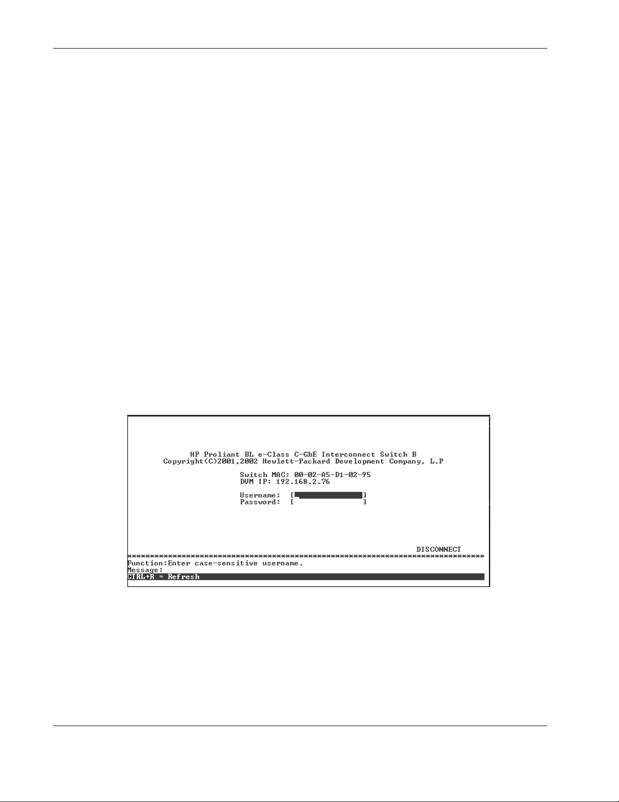
The logon screen for Switch A or Switch B will now be displayed.
IMPORTANT: The interconnect switch does not have any initial user names or passwords set. HP
recommends that after logging on, you create at least one Root-level user as the switch administrator.
(Refer to Table 2-1 in Chapter 2 for an explanation of user privileges.) If you forget your password after
it has been set up, call HP Customer Support for assistance.
1-2 HP ProLiant BL e-Class C-GbE Interconnect Switch Menu-driven Interface Reference Guide
HP CONFIDENTIAL Codename: DeLorean Part Number: 322858-001 Last Saved On: 2/4/03 11:53 AM
Page 9
Overview
To log on for the first time:
1. Leave the Username field blank and press the Tab key.
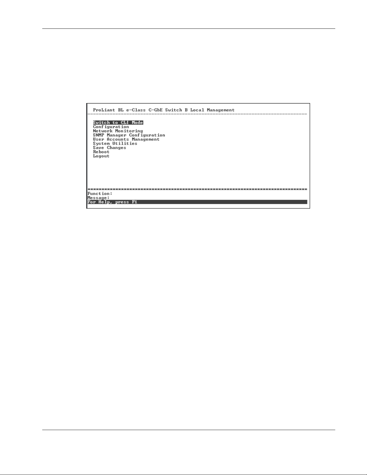
2. Leave the Password field blank and press the Enter key. The main menu for the switch
module is displayed.
NOTE: Subsequent users will type their user name and password, then press the Enter key.
The main menu displays the major categories for switch management.
Moving Between the Console Management Interfaces
The menu-driven interface is the factory default setting. To access the command line
interface (CLI) from the menu-driven interface, highlight the Switch to CLI Mode option on
the main menu and then press the Enter key. The command line prompt for the CLI will
display.
To access the menu-driven interface from the CLI, type the following command at the
command line prompt and press the Enter key:
menu
Using the Menu-driven Interface
The menu-driven interface provides many features that make configuring the switch module
and navigating through the system easy.
HP ProLiant BL e-Class C-GbE Interconnect Switch Menu-driven Interface Reference Guide 1-3
HP CONFIDENTIAL Codename: DeLorean Part Number: 322858-001 Last Saved On: 2/4/03 11:53 AM
Page 10

Overview
Navigation Features
Use the features in Table 1-1 to navigate through the screens.
Table 1-1: Menu-driven interface Navigation
To Action
Toggle between the field options Highlight items in <angle brackets>, and then press the
Enter data in a field Highlight the item in [square brackets], and then type in
Execute a command Highlight the command displayed in UPPERCASE
Move between fields on a screen
Display the previous screen
Display the main menu
Refresh the screen display
Display the next page of information
Display the previous page of information
spacebar.
the new data.
letters, and then press the Enter key.
Press the Page Up and Page Down keys, the left and
right arrow keys, the Tab key, or the Backspace key.
Press the Esc key.
Press the Ctrl+T keys.
Press the Ctrl+R keys.
Press the N key.
Press the P key.
Help and System Messages
The bottom section of each screen displays field-level help and system messages.
• • Function—Displays field-level help.
Message—Displays system messages.
Configuring the Switch Modules
After logging on to the interconnect switch for the first time, perform the following tasks for
each switch module:
1. Configure the IP address
2. Set up users, passwords, and access privileges
3. Change default SNMP community strings for read/write and read-only
For information on how to configure these and other interconnect switch features, refer to
Chapter 2.
NOTE: After configuring the IP address on the switch module, the switch module can be accessed
using Telnet, SNMP, or a Web browser. Refer to the section, “Configuring the Remote Management IP
Interface Settings,” in Chapter 2 for information on how to set up the IP address.
1-4 HP ProLiant BL e-Class C-GbE Interconnect Switch Menu-driven Interface Reference Guide
HP CONFIDENTIAL Codename: DeLorean Part Number: 322858-001 Last Saved On: 2/4/03 11:53 AM
Page 11

Configuring the Switch Modules using the Menu-driven
Interface
Overview
This chapter describes how to configure the switch modules from the menu-driven interface.
Saving Changes
The switch module has two types of memory: dynamic RAM and non-volatile RAM
(NVRAM). Restarting the switch module erases all configuration settings in RAM and
reloads the stored settings from NVRAM. Thus, it is necessary to save all configuration
setting changes to NVRAM before rebooting the switch module.
After the configuration settings have been saved to NVRAM, they become the current
runtime settings for the switch module. These settings are then used every time the switch
module is rebooted.
2
Configuration changes are made effective on a screen by highlighting APPLY, then pressing
the Enter key. When this is done, the settings are immediately applied to the switching
software in RAM.
HP ProLiant BL e-Class C-GbE Interconnect Switch Menu-driven Interface Reference Guide 2-1
HP CONFIDENTIAL Codename: DeLorean Part Number: 322858-001 Last Saved On: 2/4/03 11:56 AM
Page 12
Configuring the Switch Modules using the Menu-driven Interface
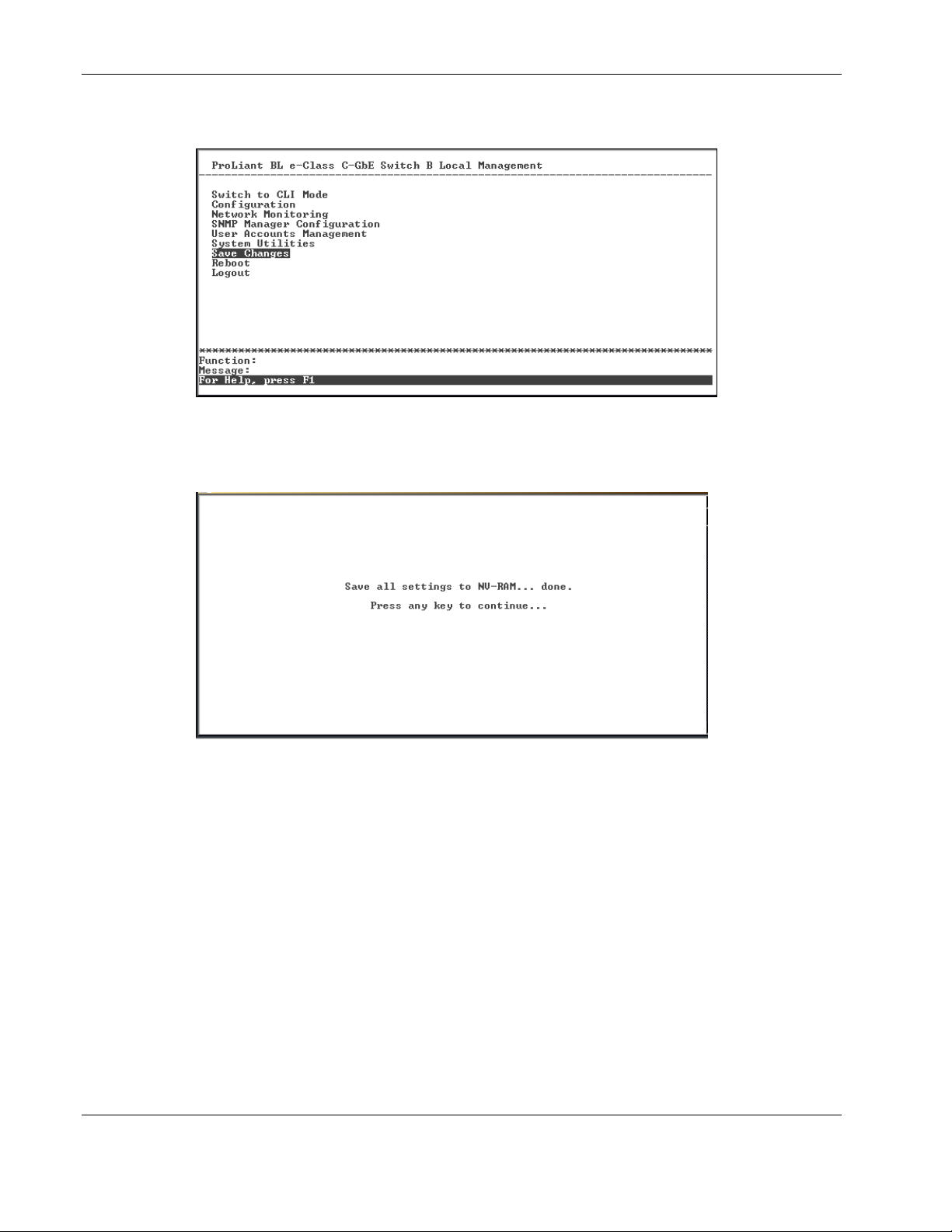
To retain any configuration changes permanently:
1. Highlight Save Changes on the main menu.
2. Press the Enter key. The following screen is displayed to verify that your new settings
have been saved to NVRAM.
After the configuration settings have been saved to NVRAM, they become the default
settings for the switch module. These settings are then used every time the switch module is
rebooted.
IMPORTANT: After saving your final configuration, HP highly recommends that you save the
configuration image to TFTP server storage. Refer to the “Saving Settings to TFTP Server” section for
more information.
2-2 HP ProLiant BL e-Class C-GbE Interconnect Switch Menu-driven Interface Reference Guide
HP CONFIDENTIAL Codename: DeLorean Part Number: 322858-001 Last Saved On: 2/4/03 11:56 AM
Page 13

Managing User Accounts
After logging on to the interconnect switch for the first time, you need to set up at least one
user account with Root privileges. You can set up a maximum of eight users on a switch
module.
There are three levels of user privileges: Root, User+, and User. Some menu selections
available to users with Root privileges may not be available to those with User+ and User
privileges.
The following table summarizes the user privileges.
Table 2-1: User Privileges
Privilege Root User+ User
Configuration Yes Read-only Read-only
Network Monitoring Yes Read-only Read-only
Community Strings and Trap Stations Yes Read-only Read-only
Update Firmware and Configuration Files Yes No No
System Utilities Yes Ping-only Ping-only
Factory Reset Yes No No
Reboot Switch Yes Yes No
Add/Update/Delete User Accounts Yes No No
View User Accounts Yes No No
Configuring the Switch Modules using the Menu-driven Interface
Adding a User Account
To create a new user account:
1. Highlight User Accounts Management on the main menu.
HP ProLiant BL e-Class C-GbE Interconnect Switch Menu-driven Interface Reference Guide 2-3
HP CONFIDENTIAL Codename: DeLorean Part Number: 322858-001 Last Saved On: 2/4/03 11:56 AM
Page 14
Configuring the Switch Modules using the Menu-driven Interface
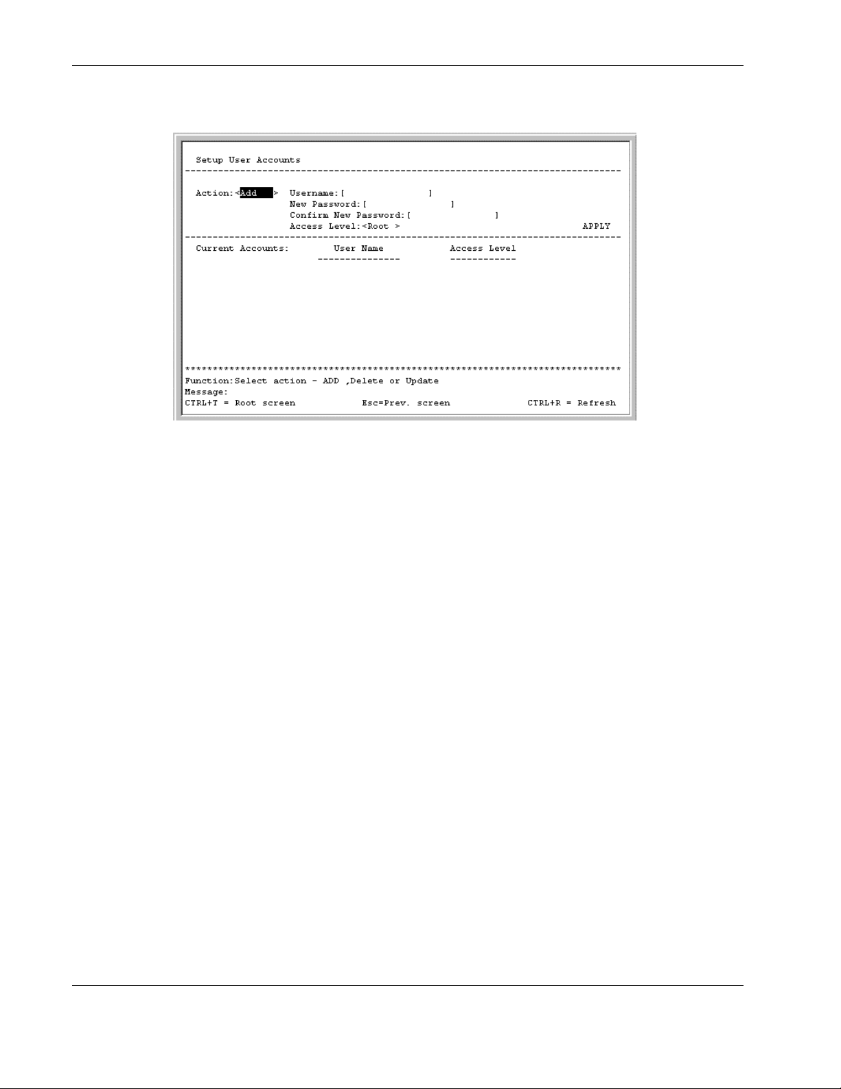
2. Press the Enter key. The Setup User Accounts screen is displayed.
3. Using the spacebar, toggle the Action field to Add.
4. Type the user’s name in the Username field.
5. Type an initial password for the user in the New Password field.
IMPORTANT: Passwords used to access the switch module are case-sensitive.
6. Type the new password a second time in the Confirm New Password field.
7. Using the spacebar, toggle the Access Level field to select the user’s access privilege.
8. Highlight APPLY.
9. Press the Enter key to make the user addition effective. A listing of all current user
accounts and access levels is displayed.
IMPORTANT: APPLY makes changes to the switch configuration for the current session only.
You must enter all permanent changes, including user additions or updates, into non-volatile RAM
(NVRAM) using the Save Changes option on the main menu. Refer to the “Saving Changes”
section for more information.
10. Press the Esc key to return to the main menu. Use the Save Changes option to save the
changes into non-volatile RAM.
2-4 HP ProLiant BL e-Class C-GbE Interconnect Switch Menu-driven Interface Reference Guide
HP CONFIDENTIAL Codename: DeLorean Part Number: 322858-001 Last Saved On: 2/4/03 11:56 AM
Page 15
Updating User Account Information
To update a user password or privilege level:
1. Highlight User Accounts Management on the main menu.
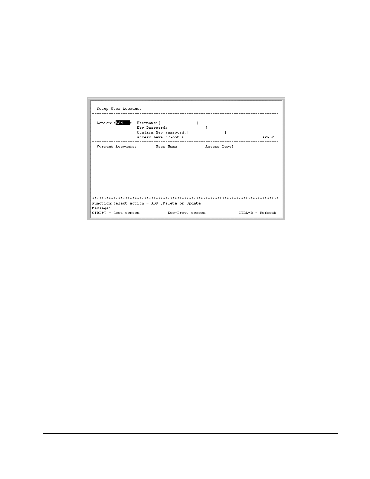
2. Press the Enter key. The Setup User Accounts screen is displayed.
Configuring the Switch Modules using the Menu-driven Interface
3. Toggle the Action field to Update.
4. Type the user name for the account you want to change in the Username field.
5. If the password is to be changed, type the new password in the New Password field.
6. Type the new password again in the Confirm New Password field.
7. If the privilege level is to be changed, toggle the Access Level field until the appropriate
level is displayed—Root, User+, or User.
8. Highlight APPLY.
9. Press the Enter key to make the change effective.
IMPORTANT: To save the configuration settings permanently, you must enter them into NVRAM
using the Save Changes option on the main menu. Refer to the “Saving Changes” section for
more information.
HP ProLiant BL e-Class C-GbE Interconnect Switch Menu-driven Interface Reference Guide 2-5
HP CONFIDENTIAL Codename: DeLorean Part Number: 322858-001 Last Saved On: 2/4/03 11:56 AM
Page 16

Configuring the Switch Modules using the Menu-driven Interface
Displaying User Account Information
To view the current user accounts:
1. Highlight User Accounts Management on the main menu.
2. Press the Enter key. The Setup User Accounts screen displays a list of all current user
accounts.
Deleting a User Account
To prevent accidental deletion of all of the users with Root privilege, the menu-driven
interface does not allow you delete the current logged-on user.
To delete a user account:
1. Highlight User Accounts Management on the main menu.
2. Press the Enter key. The Setup User Accounts screen displays a list of all current user
accounts.
3. Toggle the Action field to Delete.
4. Type the user name in the Username field.
5. Highlight APPLY.
6. Press the Enter key.
IMPORTANT: To save the configuration settings permanently, you must enter them into NVRAM
using the Save Changes option on the main menu. Refer to the “Saving Changes” section for
more information.
Configuring the Remote Management IP Interface Settings
Each switch module must be assigned its own IP address, which is used for communication
with an SNMP network manager or other TCP/IP application (for example Web or TFTP).
The factory default is set for the switch module to automatically obtain the IP address using
DHCP service from a DHCP server on the attached network. You can also manually change
the default switch IP address to meet the specification of your networking address scheme. If
you select the manual mode and do not assign the IP address, the system assigns a default IP
address for Switch A as 10.90.90.90 and for Switch B as 10.90.90.91. The system also
assigns a default subnet mask of 255.0.0.0.
The switch module IP interface is also assigned a unique MAC address by the factory. This
MAC address cannot be changed and can be found on the initial boot console screen and
Logon screen, or by accessing basic switch information. Refer to the “Displaying Basic
Interconnect Switch Information” section later in this chapter.
2-6 HP ProLiant BL e-Class C-GbE Interconnect Switch Menu-driven Interface Reference Guide
HP CONFIDENTIAL Codename: DeLorean Part Number: 322858-001 Last Saved On: 2/4/03 11:56 AM
Page 17

Configuring the Switch Modules using the Menu-driven Interface
In addition, you can
•
Set an IP address for a default gateway. This becomes necessary when the network
management station is located on a different IP network from the switch module, making
it necessary for management packets to go through a router to reach the network
manager, and vice-versa.
•
Set a list of up to eight secure IP addresses of network management stations that are
allowed to manage the interconnect switch. Only those network management stations can
access the switch management inerfaces once set.
•
Set a management VLAN ID (VID) for the IP interface so that the interconnect switch
can be accessed from the designated management VLAN.
•
Change the default SNMP community strings in the switch module and set the access
rights of these community strings.
Setting the Remote Management IP Interface Settings
To access and manage the interconnect switch from an SNMP-based Network Management
System, or by using the Telnet protocol or the Web, you must first configure the remote
management IP interface parameters.
The IP address can be assigned by one of the following methods:
•
Manual—This option allows you to manually configure an IP address, subnet mask, and
default gateway for the switch module.
•
BOOTP—This option configures the switch to send out a BOOTP broadcast request for
IP information. The BOOTP protocol allows IP addresses, network masks, and default
gateways to be assigned by a central BOOTP server attached to the same network to
which the interconnect switch is connected.
•
DHCP—This option configures the switch to send out a DHCP broadcast request. The
DHCP protocol allows IP addresses, network masks, and default gateways to be assigned
by a DHCP server attached to the same network to which the interconnect switch is
connected. DHCP protocol is the factory default mode.
HP ProLiant BL e-Class C-GbE Interconnect Switch Menu-driven Interface Reference Guide 2-7
HP CONFIDENTIAL Codename: DeLorean Part Number: 322858-001 Last Saved On: 2/4/03 11:56 AM
Page 18
Configuring the Switch Modules using the Menu-driven Interface
To set up the switch module for remote management:
1. Highlight Configure IP Address from the Configuration menu.
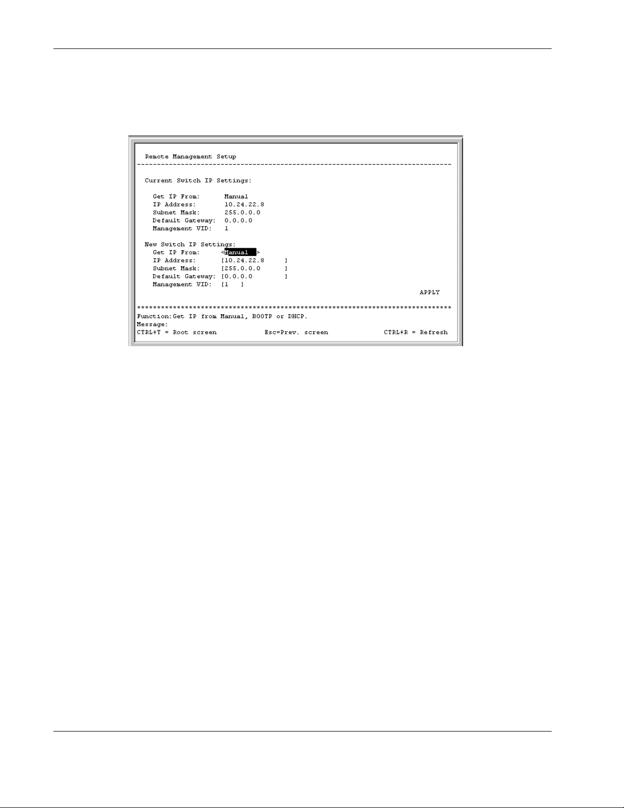
2. Press the Enter key. The following screen is displayed.
The Remote Management Setup screen lets you specify how the switch module will be
assigned an IP address, which allows an in-band network management system (for
example, Telnet) client to find it on the network.
The fields listed under the Current Switch IP Settings heading are those that are
currently being used by the switch module. Those fields listed under the New Switch IP
Settings heading are those which will be used after the switch module has been rebooted.
3. Toggle the Get IP From field to choose from Manual, BOOTP, or DHCP. This action
selects how the switch module will be assigned an IP address.
— BOOTP—The switch module sends out a BOOTP broadcast request. The BOOTP
protocol allows IP addresses, network masks, and default gateways to be assigned by
a central BOOTP server. If this option is set, the switch module first looks for a
BOOTP server to provide it with this information.
— DHCP—The switch module sends out a DHCP broadcast request. The DHCP
protocol allows IP addresses, network masks, and default gateways to be assigned by
a DHCP server. If this option is set, the switch module first looks for a DHCP server
to provide it with this information.
— Manual—This option allows the entry of an IP address, subnet mask, and default
gateway for the switch module. The data in these fields should be of the form
xxx.xxx.xxx.xxx, where each xxx is a number between 0 and 255. This address should
be a unique address on the network assigned for use by the Network Administrator.
The fields that require entries under this option include:
— Subnet Mask—A Bitmask that determines the extent of the subnet that the
switch module is on. The value should be 255.0.0.0 for a Class A network,
255.255.0.0 for a Class B network, and 255.255.255.0 for a Class C network, but
custom subnet masks are allowed.
2-8 HP ProLiant BL e-Class C-GbE Interconnect Switch Menu-driven Interface Reference Guide
HP CONFIDENTIAL Codename: DeLorean Part Number: 322858-001 Last Saved On: 2/4/03 11:56 AM
Page 19

Configuring the Switch Modules using the Menu-driven Interface
— Default Gateway—An IP address that determines where packets with a
destination address outside the current subnet should be sent. This is usually the
address of a router or a host acting as an IP gateway. If your network is not part
of an intranet, or you do not want the switch module to be accessible outside your
local network, you can leave this field blank.
If you select Manual, type the appropriate data into the IP Address, Subnet Mask, and
Default Gateway fields.
4. Type the VLAN ID (VID) of a VLAN that will have access to the Telnet manager in the
Management VID field. This ID will be the VID of the VLAN on which a management
station is located. Management of the switch module using Telnet or SNMP will be
isolated to this VLAN.
5. Highlight APPLY.
6. Press the Enter key to make the change effective.
IMPORTANT: To save the configuration settings permanently, you must enter them into NVRAM
using the Save Changes option on the main menu. Refer to the “Saving Changes” section earlier
in this chapter.
Displaying Basic Interconnect Switch Information
You can display basic information about the interconnect switch including the type of switch
and the MAC address (assigned by the factory and unchangeable). In addition, the boot
PROM and firmware version numbers display. This information is helpful in monitoring
PROM and firmware updates.
In addition, you can display advanced switch information including global settings for IGMP
snooping, GVRP, Telnet status, Web status, SNTP, and others.
To configure and display the interconnect switch information and advanced settings:
1. Highlight Configure Switch Information and Advanced Settings from the
Configuration menu.
HP ProLiant BL e-Class C-GbE Interconnect Switch Menu-driven Interface Reference Guide 2-9
HP CONFIDENTIAL Codename: DeLorean Part Number: 322858-001 Last Saved On: 2/4/03 11:56 AM
Page 20
Configuring the Switch Modules using the Menu-driven Interface
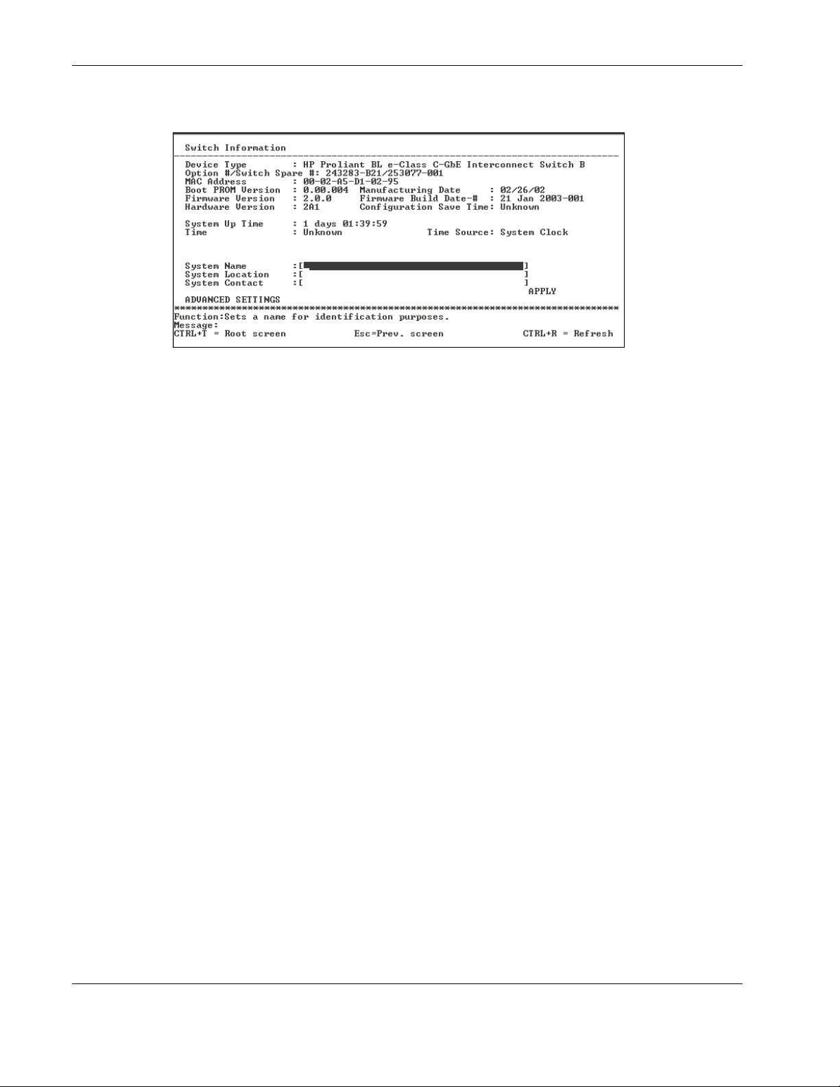
2. Press the Enter key. The following screen is displayed.
The Switch Information menu displays general information about the interconnect
switch including:
— Device Type—Identifies the interconnect switch name and module (Switch A or
Switch B).
— Option #/Switch Spare #—Identifies the option number and spare number for the
interconnect switch.
— MAC Address—Identifies the unique MAC address assigned by the factory. This
MAC address cannot be changed.
— Boot PROM Version—Identifies the version number of Boot PROM code installed
on the interconnect switch.
— Manufacturing Date—Identifies the date the interconnect switch was manufactured.
— Firmware Version—Identifies the version number of interconnect switch firmware.
— Firmware Build Date-#—Identifies the firmware build date and build number.
— Hardware Version—Identifies the version number of interconnect switch hardware
build.
— Configuration Save Time—Identifies the date and time the current settings were
saved to the configuration file.
— System Up Time—Identifies the time the switch booted up, if the current time has
been set on the switch module. If the current time has never been set up on the
interconnect switch, this field identifies the time since the switch module was booted
up.
— Time— Displays the current real time set on the switch module. If the current time
has never been set up on the interconnect switch, “Unknown” will be displayed.
— Time Source—Identifies the method in which the interconnect switch gets the
current time information: System Clock, Primary SNTP Server, or Secondary SNTP
Server.
2-10 HP ProLiant BL e-Class C-GbE Interconnect Switch Menu-driven Interface Reference Guide
HP CONFIDENTIAL Codename: DeLorean Part Number: 322858-001 Last Saved On: 2/4/03 11:56 AM
Page 21
Configuring the Switch Modules using the Menu-driven Interface
To complete the basic information:
1. Type the name of the system in the System Name field.
2. Type the location of the system in the System Location field.
3. Type the name and telephone number of the System Administrator in the System
Contact field. HP recommends that the person who is responsible for the maintenance of
the network system on which this interconnect switch is installed be listed here.
4. Highlight APPLY.
5. Press the Enter key to make the change effective.
IMPORTANT: To save the configuration settings permanently, you must enter them into NVRAM
using the Save Changes option on the main menu. Refer to the “Saving Changes” section earlier
in this chapter.
Configuring Advanced Switch Module Features
The menu-driven interface allows you to easily set advanced switch features including global
settings for IGMP snooping, GVRP, Telnet status, Web status, SNTP, and others.
To configure advanced switch module features:
1. Highlight ADVANCED SETTINGS at the bottom of the Switch Information menu.
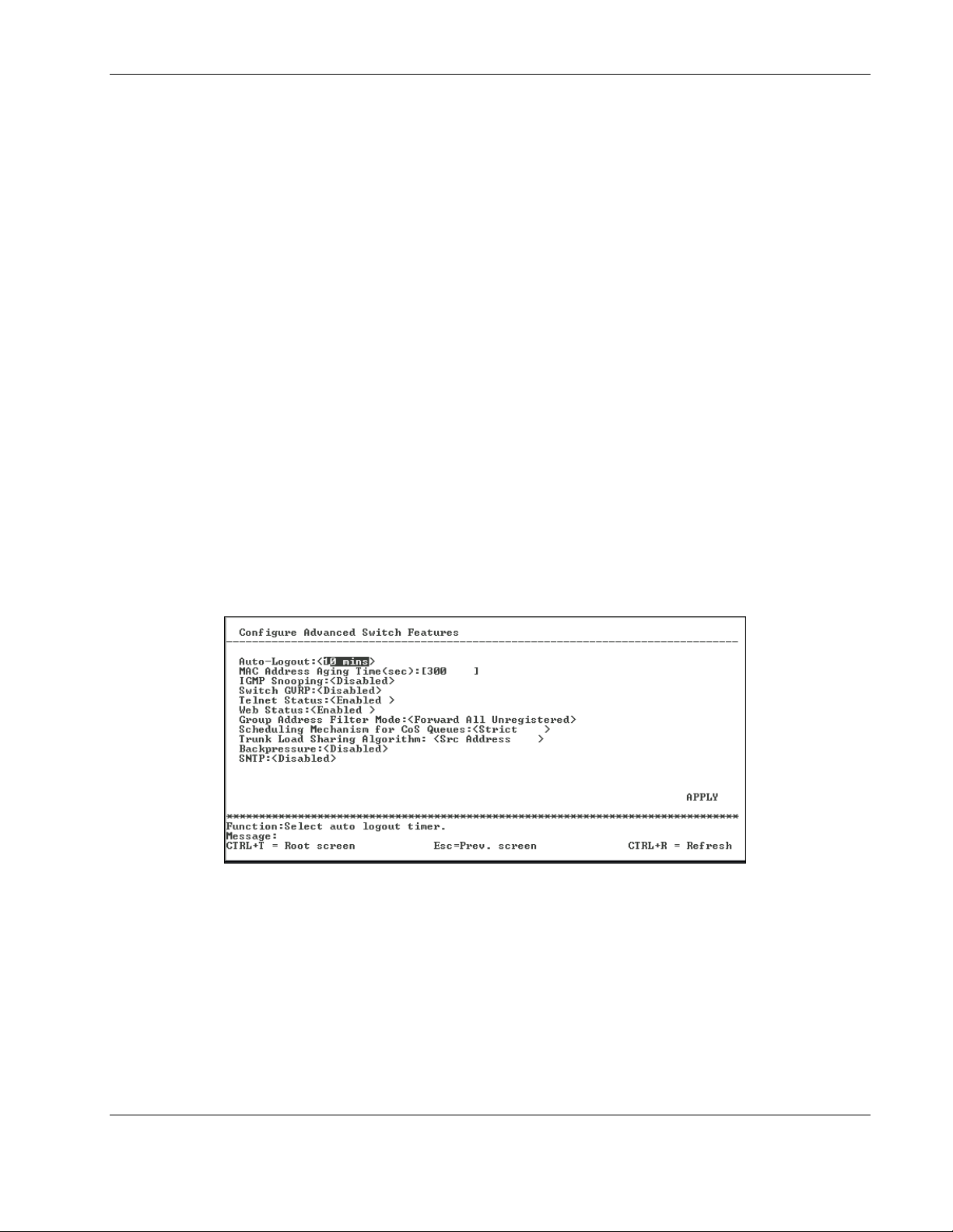
2. Press the Enter key. The following screen is displayed.
This screen allows you to set the following features:
— Auto-Logout—Toggle to select the time the RS-232 console and Telnet management
interface can be idle before the interconnect automatically logs out the user. The
options are 2 mins, 5 mins, 10 mins, 15 mins, and Never. Never indicates never
timing out. The default is 10 minutes.
— MAC Address Aging Time (sec)—Type the length of time a learned MAC address
remains in the forwarding table without being seen as a source (that is, how long a
learned MAC address is allowed to remain idle before deleting from the address
table).
HP ProLiant BL e-Class C-GbE Interconnect Switch Menu-driven Interface Reference Guide 2-11
HP CONFIDENTIAL Codename: DeLorean Part Number: 322858-001 Last Saved On: 2/4/03 11:56 AM
Page 22

Configuring the Switch Modules using the Menu-driven Interface
The switch module enters into its forwarding table the mapping between the MAC
address of the device and the Ethernet port to which the device is attached. This
information is used to forward packets. This reduces the traffic congestion on the
network, because packets are forwarded to the destination port only, instead of being
forwarded to all ports.
The MAC address aging timer prunes the forwarding table addresses entries that are
no longer used. Dynamic forwarding table entries, which are made up of MAC
addresses and their associated port numbers, are deleted from the table if they are not
seen within the aging timeout. The aging time can be from 10 to 1,000,000 seconds
with a default value of 300 seconds. A very long aging time can result in dynamic
forwarding table entries that are out-of-date or no longer are used.
If the aging time is too short, however, many entries may be aged out too soon. This
will result in a high percentage of received packets whose destination addresses
cannot be found in the forwarding table. In this case the switch module will broadcast
the packet to all ports, negating many of the benefits of having a switch.
Static forwarding entries are not affected by the aging time.
— IGMP Snooping—Toggle to enable or disable Internet Group Management Protocol
(IGMP) Snooping. IGMP snooping enables the switch module to register IGMP
packets being forwarded through the switch in order to obtain multicast membership
information from them and learn which ports are attached to which multicast group
members. For additional information, refer to the “Configuring IGMP Snooping”
section later in this chapter.
— Switch GVRP—Toggle to enable or disable GARP VLAN Registration Protocol
(GVRP) on the interconnect switch. GVRP allows dynamic propagation of VLAN
registration information across the GVRP-enabled switches on the same network. For
additional information, refer to the “Configuring GVRP” section later in this chapter.
— Telnet Status—Toggle to enable or disable access to the interconnect switch over
the network using the Telnet protocol.
— Web Status—Toggle to enable or disable use of a Web-based browser to manage the
interconnect switch.
— Group Address Filter Mode—Toggle to select the IGMP group address filter mode
for forwarding multicast packets. The options are Forward All, Forward All
Unregistered, and Filtered All Unregistered.
— Scheduling Mechanism for CoS Queues—Toggle to select the Class of Service
queue scheduling option: RoundRobin or Strict. If you select Strict, when the
highest priority queue is full, those packets are the first to be forwarded. If you select
RoundRobin, the forwarding is based on the settings made on the Class of Service
Configuration screen. For more information, refer to the “Configuring the Class of
Service, Default Port Priority, and Traffic Class” section later in this chapter.
— Trunk Load Sharing Algorithm—Toggle to select how port load sharing will be
determined. The multitrunk load sharing options are destination address, source
address, and source and destination address.
2-12 HP ProLiant BL e-Class C-GbE Interconnect Switch Menu-driven Interface Reference Guide
HP CONFIDENTIAL Codename: DeLorean Part Number: 322858-001 Last Saved On: 2/4/03 11:56 AM
Page 23
— Backpressure—Toggle to enable or disable backpressure flow control in and out of
the switch. When backpressure is enabled and there is incoming traffic congestion on
a 10/100 port, the receiving port sends a request to the transmitting port. The
transmitting port acknowledges the request and stops sending packets for a random
amount of time, before it starts sending again.
— SNTP—Toggle to enable or disable Simple Network Time Protocol (SNTP). For
additional information, refer to the “Configuring the Switch Module Date and Time”
section later in this chapter.
3. After making your changes, highlight APPLY, then press the Enter key.
IMPORTANT: To save the configuration settings permanently, you must enter them into NVRAM using
the Save Changes option on the main menu. Refer to the “Saving Changes” section earlier in this
chapter.
Configuring Port Settings
This section describes how to configure the following port settings: port name, speed/duplex
parameter, and flow control state. Refer to the “Configuring Port Security” section later in
this chapter for information on how to set the port security parameters.
Configuring the Switch Modules using the Menu-driven Interface
The speed-duplex parameter for each port can be set to 1000M/Full, 100M/Full, 100M/Half,
10M/Full, 10M/Half, or Auto. The Auto setting allows the port to automatically determine
the fastest settings that the device the port is connected to can handle.
IMPORTANT: In the forced 100M/Full, 100M/Half, 10M/Full, and 10M/Half modes, auto MDI-X is
disabled and a cross-over cable must be used.
To configure ports:
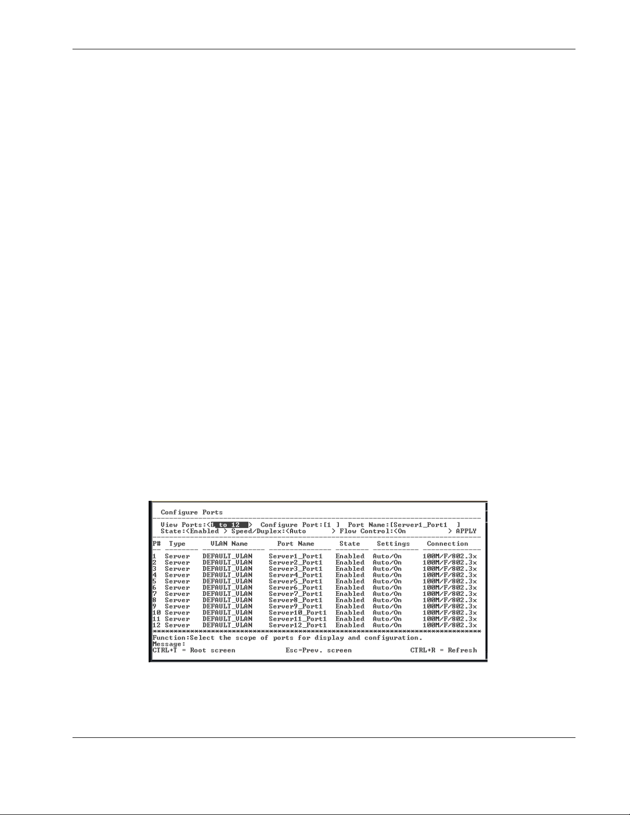
1. Highlight Configure Ports from the Configuration menu.
2. Press the Enter key. The following screen is displayed.
The Configure Ports screen allows you to configure the name, speed-duplex, and flow
control for each port
HP ProLiant BL e-Class C-GbE Interconnect Switch Menu-driven Interface Reference Guide 2-13
HP CONFIDENTIAL Codename: DeLorean Part Number: 322858-001 Last Saved On: 2/4/03 11:56 AM
Page 24

Configuring the Switch Modules using the Menu-driven Interface
3. Toggle the View Ports field, using the space bar, to display the configuration of either
Ports 1 through 12, Ports 13 through 24, or Ports 25 through 26.
4. Type the port number in the Configure Port field.
5. Type the port name in the Port Name field.
6. Toggle the State field to either enable or disable a given port.
7. Toggle the Speed/Duplex field to select the speed and duplex/half-duplex state of the
port. Auto means auto-negotiation between 10 and 100 Mb/s devices, in full- or halfduplex mode. The Auto setting allows the port to automatically determine the fastest
settings the device the port is connected to can handle. The other options are 100M/Full,
100M/Half, 10M/Full, or 10M/Half. There is no automatic adjustment of port settings
with any option other than Auto.
8. Toggle Flow Control to On or Off when.
9. Highlight APPLY.
10. Press the Enter key to make the change effective.
IMPORTANT: To save the configuration settings permanently, you must enter them into NVRAM
using the Save Changes option on the main menu. Refer to the “Saving Changes” section earlier
in this chapter.
Configuring Bandwidth
The GbE Interconnect Switch allows you to set a bandwidth limitation that restricts the
ingress (receiving) and egress (transmitting) packet rate for each port. If the packet rate
exceeds the allowed bandwidth rate, the excess packets will be dropped.
Bandwidth is configured in 1 to 127 units. Each unit is 117,481 bytes per second (around 0.94
Mb/s) for ports 1-26 and 939,850 bytes (about 7.52 Mb/s) for optional ports.
To configure bandwidth:
1. Highlight Configure Bandwidth on the Configuration menu.
2-14 HP ProLiant BL e-Class C-GbE Interconnect Switch Menu-driven Interface Reference Guide
HP CONFIDENTIAL Codename: DeLorean Part Number: 322858-001 Last Saved On: 2/4/03 11:56 AM
Page 25
Configuring the Switch Modules using the Menu-driven Interface
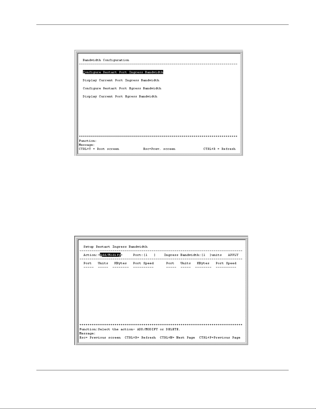
2. Press the Enter key. The following screen is displayed.
The Bandwidth Configuration menu allows you to access screens that set and display the
ingress bandwidth and egress bandwidth of specified ports on the switch module.
Configuring Restart Port Ingress Bandwidth
To configure restart port ingress bandwidth:
1. Highlight Configure Restart Port Ingress Bandwidth on the Bandwidth
Configuration menu.
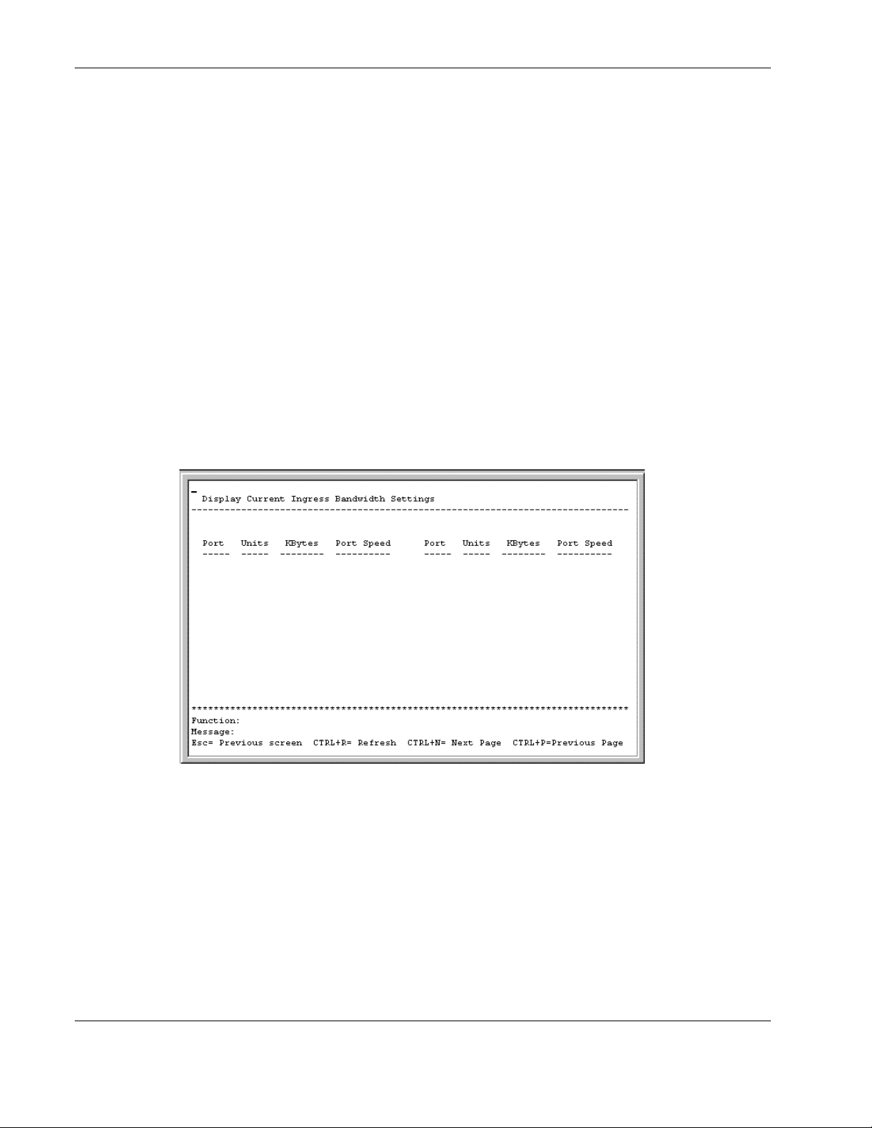
2. Press Enter. The following screen is displayed.
3. Toggle the Action field to Add/Modify.
HP ProLiant BL e-Class C-GbE Interconnect Switch Menu-driven Interface Reference Guide 2-15
HP CONFIDENTIAL Codename: DeLorean Part Number: 322858-001 Last Saved On: 2/4/03 11:56 AM
Page 26
Configuring the Switch Modules using the Menu-driven Interface
NOTE: To delete an entry, toggle the Action field to Delete.
4. Type a port number in the Port field.
5. Type a number between 1 and 127 in the Ingress Bandwidth field.
6. Highlight APPLY.
7. Press the Enter key.
8. Save the changes using Save Changes on the main menu.
9. Reboot the switch module to allow your changes to take effect.
Displaying Current Port Ingress Bandwidth
To view the current port ingress bandwidth settings:
1. Highlight Display Current Port Ingress Bandwidth on the Bandwidth
Configuration menu.
2. Press the Enter key. The following screen is displayed.
This read-only screen displays current ingress bandwidth information.
2-16 HP ProLiant BL e-Class C-GbE Interconnect Switch Menu-driven Interface Reference Guide
HP CONFIDENTIAL Codename: DeLorean Part Number: 322858-001 Last Saved On: 2/4/03 11:56 AM
Page 27
Configuring the Switch Modules using the Menu-driven Interface
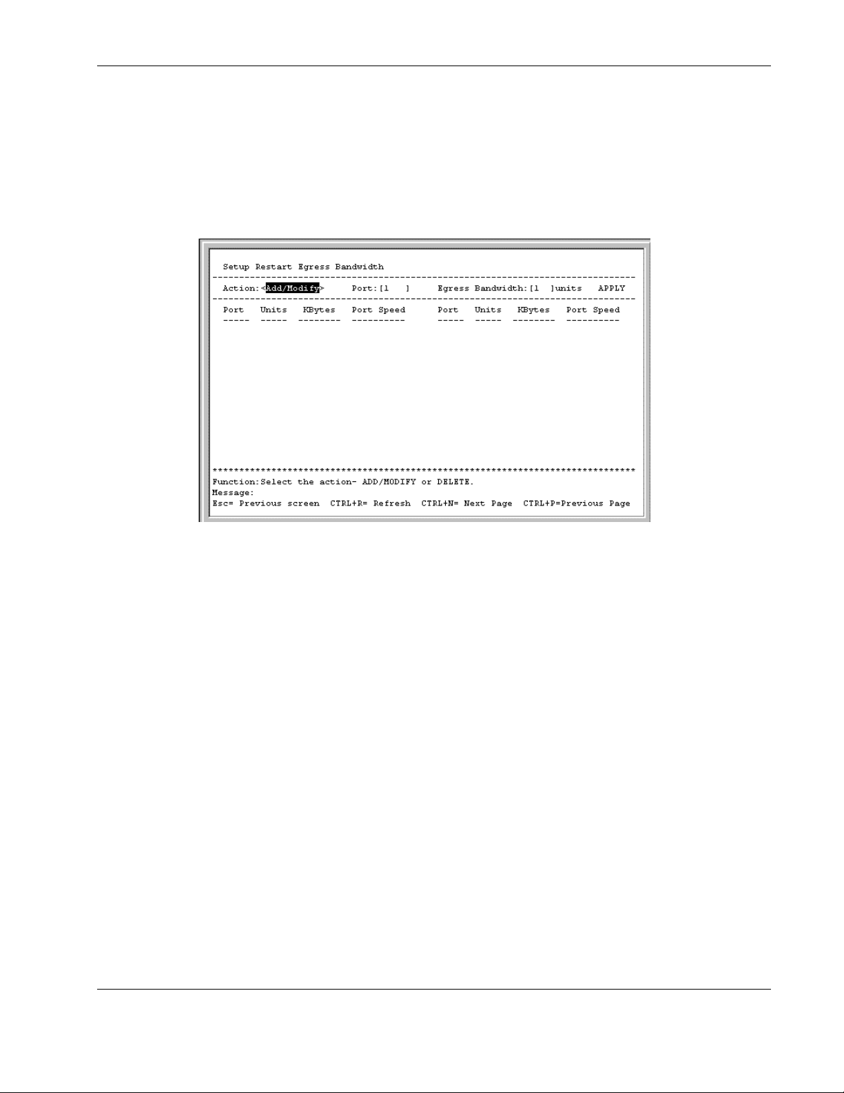
Configuring Restart Port Egress Bandwidth
To configure port egress bandwidth:
1. Highlight Configure Restart Port Egress Bandwidth on the Bandwidth
Configuration screen.
2. Press the Enter key. The following screen is displayed.
3. Toggle to Add/Modify in the Action field.
NOTE: To delete an entry, toggle the Action field to Delete.
4. Type a destination port in the Port field.
5. Type a number between 1 and 127 in the Egress Bandwidth field.
6. Highlight APPLY.
7. Press the Enter key.
8. Save the changes using Save Changes on the main menu.
9. Reboot the switch module to allow your changes take effect.
HP ProLiant BL e-Class C-GbE Interconnect Switch Menu-driven Interface Reference Guide 2-17
HP CONFIDENTIAL Codename: DeLorean Part Number: 322858-001 Last Saved On: 2/4/03 11:56 AM
Page 28
Configuring the Switch Modules using the Menu-driven Interface
Displaying Current Port Egress Bandwidth Settings
To view port egress bandwidth settings:
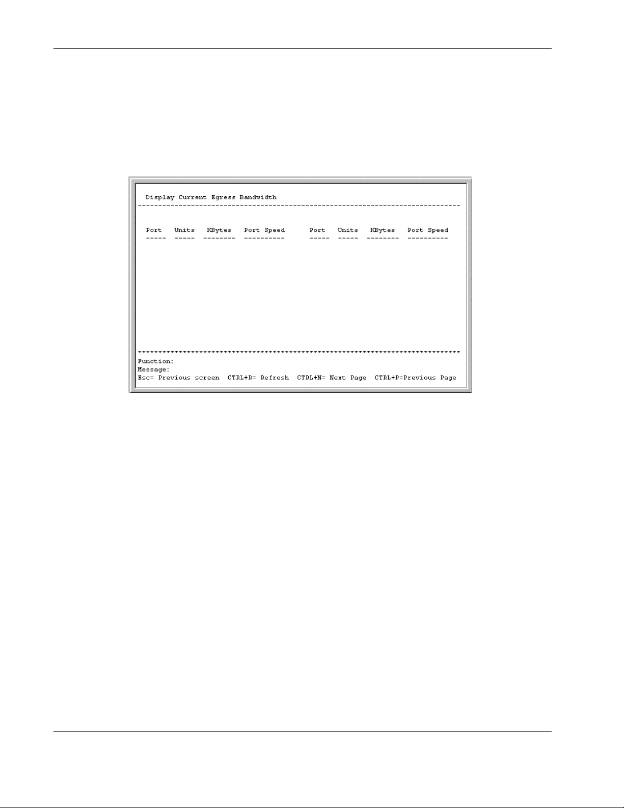
1. Highlight Display Current Port Egress Bandwidth on the Bandwidth
Configuration menu.
2. Press the Enter key. The following screen is displayed.
This read-only screen displays current egress bandwidth information.
2-18 HP ProLiant BL e-Class C-GbE Interconnect Switch Menu-driven Interface Reference Guide
HP CONFIDENTIAL Codename: DeLorean Part Number: 322858-001 Last Saved On: 2/4/03 11:56 AM
Page 29

Configuring the Switch Modules using the Menu-driven Interface
Configuring Spanning Tree Protocol
IEEE 802.1D Spanning Tree Protocol (STP) allows for the blocking of links between
switches to avoid loops within the network. When multiple links between the switches are
detected, a primary link is established. Duplicated links are blocked from use and become
standby links. The protocol allows for the duplicate links to be used in the event of a failure
of the primary link. Once STP is configured and enabled, primary links are established and
duplicated links are blocked and put into standby automatically. The reactivation of the
blocked links (at the time of a primary link failure) is also accomplished automatically,
without operator intervention.
STP communicates between switches on the network using Bridge Protocol Data Units
(BPDUs). Each BPDU contains the following information:
•
The unique identifier of the switch that the transmitting switch currently believes is the
root switch
•
The path cost to the root from the transmitting port
•
The port identifier of the transmitting port
The switch sends BPDUs to communicate and construct the spanning-tree topology. All
switches connected to the LAN on which the packet is transmitted will receive the BPDU.
BPDUs are not directly forwarded by the switch, but the receiving switch uses the
information in the frame to calculate a BPDU, and if the topology changes, initiates a BPDU
transmission.
The communication between switches via BPDUs results in the following:
•
One switch is elected as the root switch.
•
The shortest distance to the root switch is calculated for each switch.
•
A designated switch is selected. This is the switch closest to the root switch through
which packets will be forwarded to the root.
•
A port for each switch is selected. This is the port providing the best path from the switch
to the root switch.
•
Ports included in the STP are selected.
Spanning Tree Protocol (STP) can be enabled or disabled at the switch level. Only one
spanning tree domain per switch module is supported. You can configure ports to participate
in that spanning tree domain, by enabling or disabling the STP function on a per port basis.
Ports can also be configured in STP bypass mode (fast forward mode) that allows the port to
skip the initial STP states (listening and learning) before enabling it in the forwarding state.
IMPORTANT: The interconnect switch supports mono-Spanning Tree Protocol. Multiple Spanning Tree
domains are not supported.
NOTE: Refer to Appendix D in the HP ProLiant BL e-Class C-GbE Interconnect Switch User Guide for
more information on Spanning Tree Protocol.
HP ProLiant BL e-Class C-GbE Interconnect Switch Menu-driven Interface Reference Guide 2-19
HP CONFIDENTIAL Codename: DeLorean Part Number: 322858-001 Last Saved On: 2/4/03 11:56 AM
Page 30
Configuring the Switch Modules using the Menu-driven Interface
Setting Spanning Tree Parameters on the Switch Module Level
IMPORTANT: The factory default settings should cover the majority of installations. HP recommends
that you keep the default settings as set at the factory unless it is absolutely necessary to change them.
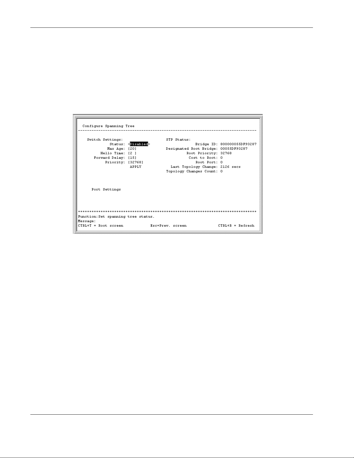
To globally configure Spanning Tree Protocol (STP) on the switch module:
1. Highlight Configure Spanning Tree Protocol on the Configuration menu.
2. Press the Enter key. The following screen is displayed.
The Configure Spanning Tree screen allows you to set the global STP parameters and
displays the STP status.
You can set the following:
— Status—Toggle to Enabled to implement STP on the switch module.
— Max Age—The maximum age can be set from 6 to 40 seconds. At the end of the
maximum age, if a Bridge Protocol Data Unit (BPDU) has still not been received
from the root bridge, your switch module will start sending its own BPDU to all other
switches for permission to become the root bridge. If your switch module has the
lowest bridge identifier, it will become the root bridge.
— Hello Time—The hello time can be set from 1 to 10 seconds. This is the interval
between two transmissions of BPDU packets sent by the root bridge to tell all other
switches that it is indeed the root bridge. If you set a hello time for your switch
module, and it is not the root bridge, the set hello time will be used if and when your
switch module becomes the root bridge. The hello time cannot be longer than the
maximum age, otherwise, a configuration error will occur.
— Forward Delay—The forward delay can be from 4 to 30 seconds. This is the time
any port on the switch module spends in the listening state while moving from the
blocking state to the forwarding state.
2-20 HP ProLiant BL e-Class C-GbE Interconnect Switch Menu-driven Interface Reference Guide
HP CONFIDENTIAL Codename: DeLorean Part Number: 322858-001 Last Saved On: 2/4/03 11:56 AM
Page 31

Configuring the Switch Modules using the Menu-driven Interface
— Priority—A priority for the switch module can be set from 0 to 65,535. Zero
indicates the highest priority. The priority number is used in the voting process
between switches on the network to determine which switch will be the root switch.
A low number indicates a high priority, and a higher probability that this switch
module will be elected as the root switch.
IMPORTANT: Observe the following formulas when setting the STP parameters for the root
switch:
• Max Age ≤ 2 x (Forward Delay - 1 second)
• Max Age ≥ 2 x (Hello Time + 1 second)
3. After making your changes, highlight APPLY, then press the Enter key.
IMPORTANT: To save the configuration settings permanently, you must enter them into NVRAM
using the Save Changes option on the main menu. Refer to the “Saving Changes” section earlier
in this chapter.
The screen also displays STP status information, including:
— Bridge ID—The ID of the bridge (switch) used only for spanning tree functions. The
ID is made up of the bridge priority and bridge MAC address.
— Designated Root Bridge—The current elected root bridge. The root bridge has a
bridge ID lower than the other bridges.
— Root Priority—The priority of the current designated root bridge
— Cost to Root—The summation of all path costs between the current bridge and the
root bridge via the root port
— Root Port—The port on the current bridge that has the best path to reach the
designated root bridge.
— Last Topology Change—The number of seconds since the last change in topology
occurred that caused the spanning tree algorithm to be recalculated
— Topology Changes Count—The number of times there has been a change in
topology since the last reboot of the current bridge
Setting Spanning Tree Parameters at the Port Level
Once STP is enabled on the switch, you can configure ports to participate in the spanning tree
domain, by enabling or disabling the STP function on a per port basis. Ports can also be
configured in STP bypass mode (fast forward mode) that allows the port to skip the initial
STP states (listening and learning) before enabling it in the forwarding state.
HP ProLiant BL e-Class C-GbE Interconnect Switch Menu-driven Interface Reference Guide 2-21
HP CONFIDENTIAL Codename: DeLorean Part Number: 322858-001 Last Saved On: 2/4/03 11:56 AM
Page 32
Configuring the Switch Modules using the Menu-driven Interface
To define individual ports:
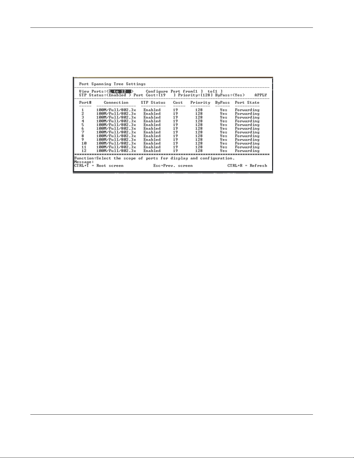
1. Highlight Port Settings on the Configure Spanning Tree menu.
2. Press the Enter key. The following screen is displayed.
3. Toggle the View Ports field to the range of ports to be displayed.
4. Type the port number or port range in the Configure Port field.
5. Toggle the STP Status field to Enabled or Disabled.
6. Type the Spanning Tree port cost in the Port Cost field. Port cost is a value used by STP
to evaluate paths. STP calculates port costs and selects the path with the minimum cost as
the active path.
7. Type the Spanning Tree priority in the Priority field. This parameter sets the relative
priority for the port. A lower number indicates a higher priority and a greater chance of
the port being elected as the root port.
8. Toggle the ByPass field to Yes to enable the switch module to skip the usual waiting
time associated with the listening state. (This is also known as fast forward.)
9. Highlight APPLY.
10. Press the Enter key.
IMPORTANT: To save the configuration settings permanently, you must enter them into NVRAM
using the Save Changes option on the main menu. Refer to the “Saving Changes” section earlier
in this chapter.
Configuring Static (Destination Address) Filtering Table
The switch module uses a filtering database to segment the network and control
communications between segments. It can also filter packets off the network for intrusion
control. Static filtering entries can be made by MAC address.
Each port on the switch module is a unique collision domain. The switch module filters
(discards) packets whose destination lies on the same port as where it originated. This keeps
local packets from disrupting communications on other parts of the network.
2-22 HP ProLiant BL e-Class C-GbE Interconnect Switch Menu-driven Interface Reference Guide
HP CONFIDENTIAL Codename: DeLorean Part Number: 322858-001 Last Saved On: 2/4/03 11:56 AM
Page 33
Configuring the Switch Modules using the Menu-driven Interface
For intrusion control, whenever a switch module encounters a packet originating from or
destined to a MAC address entered into the filter table, the switch module discards the packet.
Some filtering is done automatically by the switch module, including:
•
Dynamic filtering, which is automatic learning and aging of MAC addresses and their
location on the network. Filtering occurs to keep local traffic confined to its segment.
•
Filtering done by the Spanning Tree Protocol that can filter packets based on topology,
making sure that the signal loops do not occur.
•
Filtering done for VLAN integrity. Packets from a member of a VLAN destined for a
device on another VLAN will be filtered.
Some filtering requires the manual entry of information into a filtering table. This includes
MAC address filtering, which is the manual entry of specific MAC addresses to be filtered
from the network. Packets sent from one manually entered MAC address can be filtered from
the network. The entry may be specified as source, destination, or both.
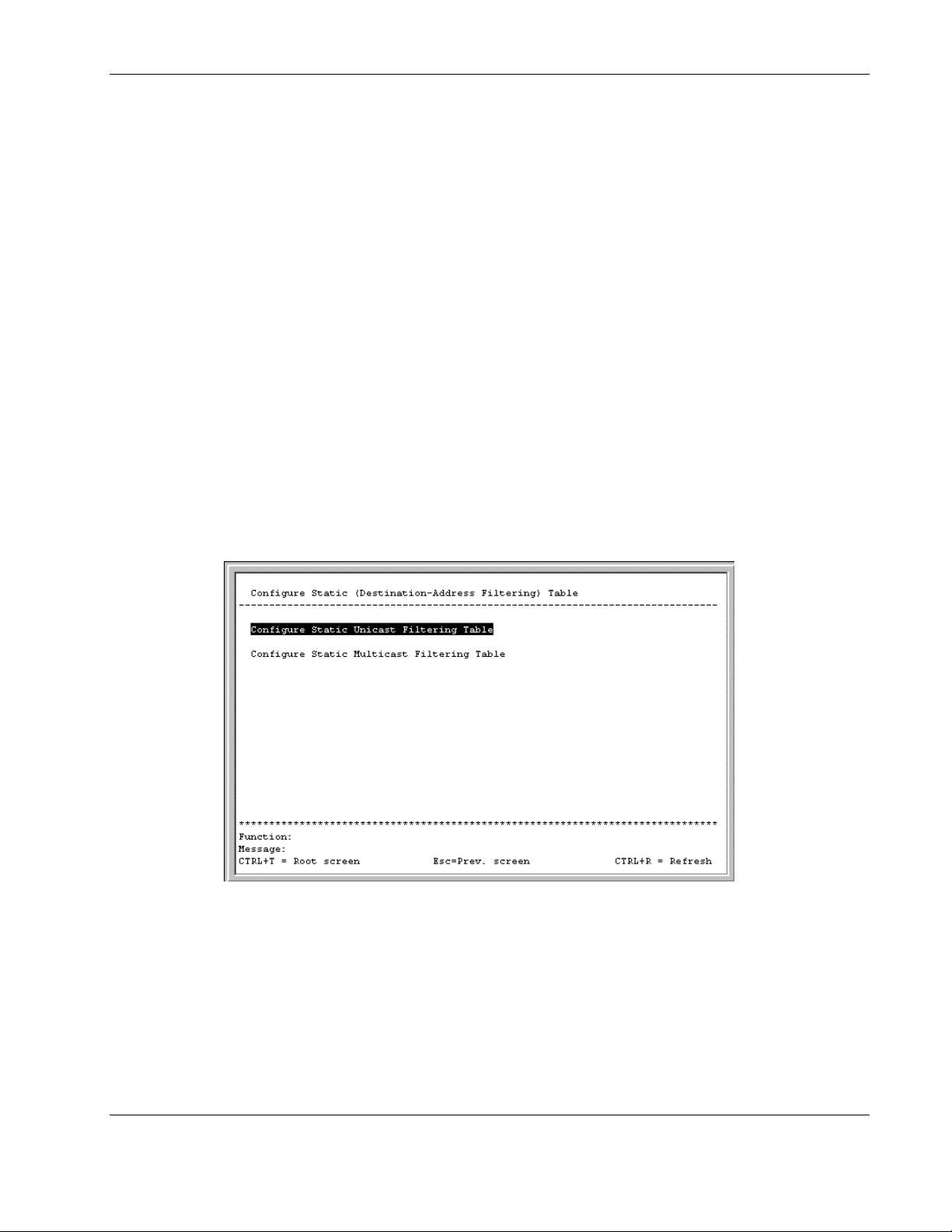
To configure the Static (Destination-Address Filtering) Table:
1. Highlight Configure Static (Destination-Address Filtering) Table on the
Configuration menu.
2. Press the Enter key. The following screen is displayed.
The Configure Static (Destination-Address Filtering) Table menu allows you to access
screens to create, modify, and delete both the Static Unicast Filtering Table and the Static
Multicast Filtering Table.
HP ProLiant BL e-Class C-GbE Interconnect Switch Menu-driven Interface Reference Guide 2-23
HP CONFIDENTIAL Codename: DeLorean Part Number: 322858-001 Last Saved On: 2/4/03 11:56 AM
Page 34
Configuring the Switch Modules using the Menu-driven Interface
Adding Unicast Filter Actions
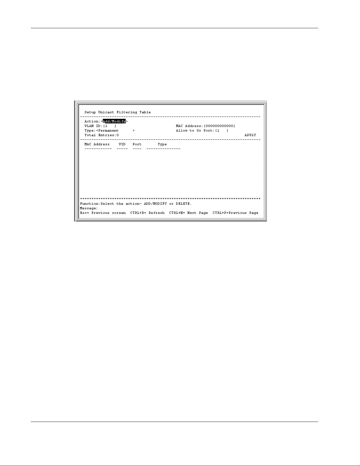
To configure the Static Unicast Table:
1. Highlight Configure Static Unicast Table on the Configure Static (Destination-
Address Filtering) Table menu.
2. Press the Enter key. The following screen is displayed.
3. Toggle the Action field to Add/Modify.
NOTE: To delete the unicast filter action for a VLAN, toggle the Action field to Delete.
4. Type the VID in the VLAN ID field.
5. Type the MAC address to be statically entered in the forwarding table in the MAC
Address field.
6. Toggle the Type field to Permanent or DeleteOnReset, to set the unicast filter type.
Permanent maintains the filter permanently, until reconfigured. DeleteOnReset deletes
the filter when the port is reset.
7. Type the port number in the Allow to Go Port field.
8. Highlight APPLY.
9. Press the Enter key.
IMPORTANT: To save the configuration settings permanently, you must enter them into NVRAM
using the Save Changes option on the main menu. Refer to the “Saving Changes” section earlier
in this chapter.
2-24 HP ProLiant BL e-Class C-GbE Interconnect Switch Menu-driven Interface Reference Guide
HP CONFIDENTIAL Codename: DeLorean Part Number: 322858-001 Last Saved On: 2/4/03 11:56 AM
Page 35
Adding Multicast Filter Actions
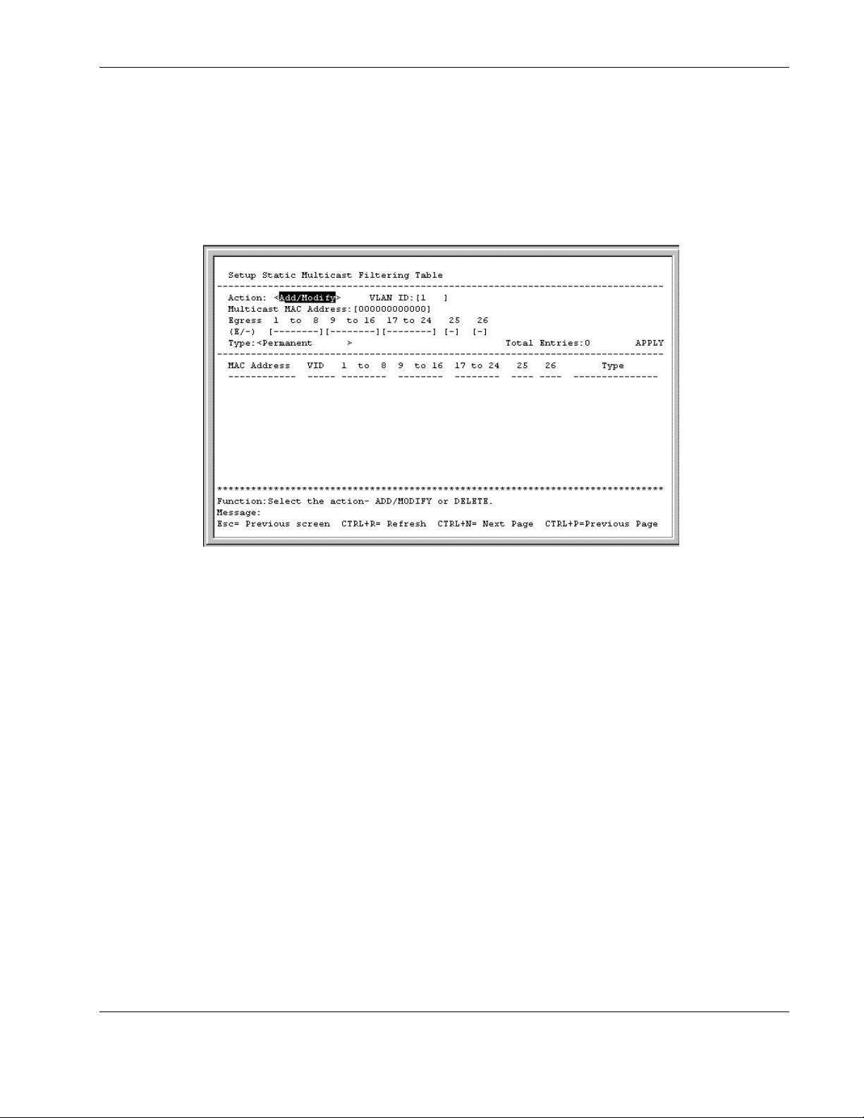
To edit the multicast filtering settings:
1. Highlight Configure Static Multicast Filtering Table on the Configure Static
(Destination-Address Filtering) Table.
2. Press the Enter key. The following screen is displayed.
Configuring the Switch Modules using the Menu-driven Interface
3. Toggle the Action field to Add/Modify.
4. Type the VID number of the VLAN that will be receiving the multicast packets in the
VLAN ID field.
5. Type the MAC address of the multicast source in the Multicast MAC Address field.
6. Set the multicast group membership of each port by highlighting (E/-) field using the
arrow keys, and then toggling between E, F, or — using the space bar.
a. E (Egress Member)—Specifies the port as being a static member of the multicast
group. Egress Member Ports are ports that transmit traffic for the multicast group.
b. F (Forbidden Nonmember)—Specifies the port as not being a member of the
multicast group and that the port is forbidden from becoming a member of the
multicast group dynamically.
c. — (Nonmember)—Specifies the port as not being a member of the multicast group,
but the port can become a member of the multicast group dynamically.
7. Toggle the Type field to the static multicast filter type Permanent or DeleteOnReset.
8. Highlight APPLY.
9. Press the Enter key.
IMPORTANT: To save the configuration settings permanently, you must enter them into NVRAM
using the Save Changes option on the main menu. Refer to the “Saving Changes” section earlier
in this chapter.
HP ProLiant BL e-Class C-GbE Interconnect Switch Menu-driven Interface Reference Guide 2-25
HP CONFIDENTIAL Codename: DeLorean Part Number: 322858-001 Last Saved On: 2/4/03 11:56 AM
Page 36

Configuring the Switch Modules using the Menu-driven Interface
Configuring VLANs
A Virtual Local Area Network (VLAN) is a network topology configured according to a
logical scheme rather than the physical layout. VLANs can be used to combine any collection
of physical LAN segments into an autonomous user group that appears as a single LAN.
VLANs also logically segment the network into different broadcast domains so that logical
packets are forwarded only between ports within that VLAN. Typically, a VLAN
corresponds to a particular subnet, although not necessarily. VLANs can enhance
performance by conserving bandwidth, and improve security by limiting traffic to specific
domains.
The switch module supports only port-based IEEE 802.1Q tag-capable VLANs.
VLAN membership for each port can be set as follows:
• • Egress Port—This is a port on the interconnect switch that belongs to at least one
VLAN. By default all ports are egress members of DEFAULT_VLAN.
— Untagged Member—Ports that are untagged members of a VLAN participate in the
VLAN, but no tag is associated to the packet when leaving that port. Untagged
member ports can only be a member of one VLAN at a time.
If ingress filtering is enabled for a port, the interconnect switch examines the VLAN
information in the packet header (if present) and decides whether or not to forward the
packet. The VID should match the PVID of that port, otherwise, that incoming packet is
discarded.
Packets cannot cross VLANs. If a member of one VLAN wants to connect to another VLAN,
it must do so through a router.
Default VLAN
The switch module reserves one VLAN, VID 1, also called DEFAULT_VLAN. The factory
default setting assigns all ports on the switch module to the default VLAN. As new VLANs
are configured, their respective member ports are removed from the default VLAN.
— Tagged Member—Ports with tagging enabled will insert the IEEE 802.1Q tag with
the VID number into all packets that flow out of it. Tagged member ports can be
members of multiple VLANs at a time, as packets are tagged with the VLAN ID
from which they originated. Tagged member ports link IEEE 802.1Q trunks that
work as inter-switch connections to forward packets belonging to multiple VLANs,
to which those tagged member ports belong. If a packet has been tagged, the port
does not alter the packet, thus keeping the VLAN information intact. The VLAN
information in the tag can then be used by other 802.1Q compliant devices on the
network to make packet-forwarding decisions.
Forbidden Non-member—These ports are not a member of the VLAN and are also
forbidden from joining a VLAN dynamically when GVRP is enabled.
2-26 HP ProLiant BL e-Class C-GbE Interconnect Switch Menu-driven Interface Reference Guide
HP CONFIDENTIAL Codename: DeLorean Part Number: 322858-001 Last Saved On: 2/4/03 11:56 AM
Page 37
Configuring the Switch Modules using the Menu-driven Interface
Characteristics of DEFAULT_VLAN include:
•
DEFAULT_VLAN is an IEEE 802.1Q Static VLAN with VID equal to 1.
•
DEFAULT_VLAN cannot be deleted.
•
The VID cannot be changed. The VID that is equal to 1 is reserved for
DEFAULT_VLAN.
•
The VLAN name can be changed to any other valid VLAN name.
•
You cannot delete a port from DEFAULT_VLAN, unless it is a member of another
802.1Q VLAN.
•
You cannot forbid a port from DEFAULT_VLAN, unless it is a member of another
802.1Q VLAN.
•
If a port is deleted from the only 802.1Q VLAN of which it is a member, then it will
automatically become a member of DEFAULT_VLAN as an untagged, egress port.
•
If a port is assigned to a user-created 802.1Q VLAN, and is not a tagged egress port
member of DEFAULT_VLAN (in other words, it is an untagged egress port), then it will
be deleted automatically from DEFAULT_VLAN.
•
A tagged egress port of DEFAULT_VLAN will not be deleted from DEFAULT_VLAN,
when it is assigned to another user-created 802.1Q VLAN.
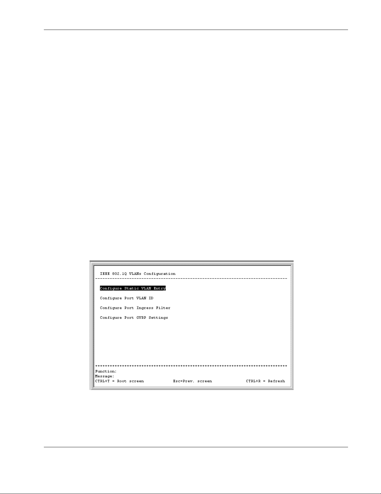
To edit VLAN definitions and to configure port settings for IEEE 802.1Q VLAN support:
1. Highlight Configure VLANs on the Configuration menu.
2. Press the Enter key. The following screen is displayed.
HP ProLiant BL e-Class C-GbE Interconnect Switch Menu-driven Interface Reference Guide 2-27
HP CONFIDENTIAL Codename: DeLorean Part Number: 322858-001 Last Saved On: 2/4/03 11:56 AM
Page 38
Configuring the Switch Modules using the Menu-driven Interface
Creating an 802.1 Static VLAN
To create an 802.1Q VLAN:
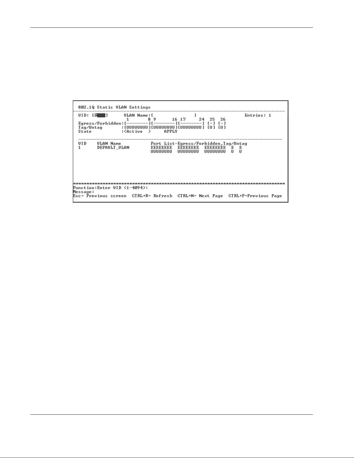
1. Highlight Configure Static VLAN Entry on the IEEE 802.1Q VLANs
Configuration menu.
2. Press the Enter key. The following screen is displayed.
3. Type a VLAN ID number in the VID field.
4. Type a name for the new VLAN in the VLAN Name field.
5. Set the 802.1Q VLAN membership for each port by highlighting the Egress/Forbidden
field using the arrow keys, and then toggling between E, F, and — using the space bar.
— E (Egress Member)—Specifies the port as being a static member of the VLAN.
Egress Member Ports are ports that will be transmitting traffic for the VLAN. These
ports can be either tagged or untagged.
— F (Forbidden Nonmember)—Defines the port as not being a member and also forbids
the port from joining a VLAN dynamically.
— — (Nonmember)—Specifies the port as not being a member of the VLAN, but the
port can become a member of the VLAN dynamically.
6. Set the state of each port by highlighting the Tag/Untag field using the arrow keys and
then toggling between U or T using the space bar.
— U—Specifies the port as an untagged member of the VLAN. When the port transmits
an untagged packet, the packet header remains unchanged. When a tagged packet
exits the port, the tag is stripped and the packet is changed to an untagged packet.
— T—Specifies the port as a tagged member of the VLAN. When the port transmits an
untagged packet, the packet header is changed to include the 32-bit tag associated
with the PVID (Port VLAN Identifier—refer to the following section). When a
tagged packet exits the port, the packet header is unchanged.
2-28 HP ProLiant BL e-Class C-GbE Interconnect Switch Menu-driven Interface Reference Guide
HP CONFIDENTIAL Codename: DeLorean Part Number: 322858-001 Last Saved On: 2/4/03 11:56 AM
Page 39

Configuring the Switch Modules using the Menu-driven Interface
IMPORTANT: If the port is attached to a device that is not IEEE 802.1Q VLAN compliant (VLANtag unaware), then set the port to U—Untagged. If the port is attached to a device that is IEEE
802.1Q VLAN compliant, (VLAN-tag aware), then set the port to T—Tagged.
7. Toggle the State field between Active and Inactive.
8. Highlight APPLY.
9. Press the Enter key.
IMPORTANT: To save the configuration settings permanently, you must enter them into NVRAM
using the Save Changes option on the main menu. Refer to the “Saving Changes” section earlier
in this chapter.
Setting the PVID for a Port for a Specific VLAN
Port VLAN ID (PVID) is a classification mechanism that associates a port with a specific
VLAN and is used to make forwarding decisions for untagged packets received by the port.
For example, if Port 2 is assigned a PVID of 3, then all untagged packets received on Port 2
will be assigned to VLAN 3. This number is generally the same as the VID number assigned
to the port.
Characteristics of a PVID include:
•
By default, the PVID of all ports is the same as the VID of DEFAULT_VLAN, which is
equal to 1.
•
When a user creates an untagged 802.1Q VLAN and assigns a port, the PVID will be
changed to the VID of that 802.1Q VLAN.
•
For a tagged port, the PVID will be the same as the VID of the IEEE 802.1Q VLAN to
which this port was first assigned.
•
If the first IEEE 802.1Q VLAN to which the tagged port is assigned is deleted, the PVID
will change to that of the second IEEE 802.1Q VLAN to which the port was assigned.
•
The PVID of a port can only be set to a VID of a VLAN for which the port is already a
member.
HP ProLiant BL e-Class C-GbE Interconnect Switch Menu-driven Interface Reference Guide 2-29
HP CONFIDENTIAL Codename: DeLorean Part Number: 322858-001 Last Saved On: 2/4/03 11:56 AM
Page 40
Configuring the Switch Modules using the Menu-driven Interface
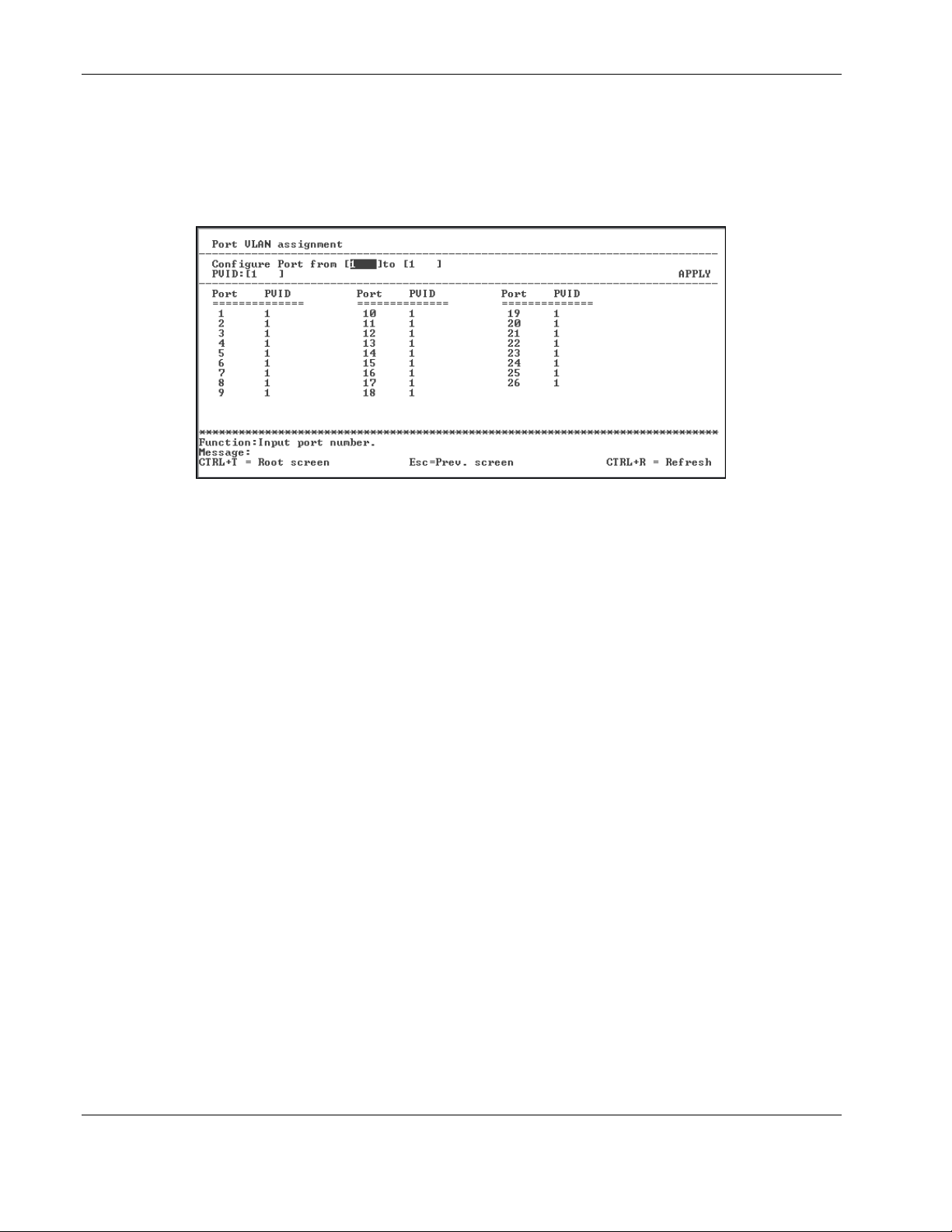
To assign a port a PVID:
1. Highlight Configure Port VLAN ID on the IEEE 802.1Q VLANs
Configuration menu.
2. Press the Enter key. The following screen is displayed.
3. Type the range of port numbers you want to configure in the Configure Port field.
4. Type the PVID for the VLAN member ports you want to configure in the PVID field.
Port VLAN Identifier (PVID) is a classification mechanism that associates a port with a
specific VLAN and is used to make forwarding decisions for untagged packets received
by the port. For example, if Port 2 is assigned a PVID of 3, then all untagged packets
received on Port 2 will be assigned to VLAN 3. This number is generally the same as the
VID# number assigned to the port in the 802.1Q Static VLAN Settings screen.
5. Highlight APPLY.
6. Press the Enter key.
IMPORTANT: To save the configuration settings permanently, you must enter them into NVRAM
using the Save Changes option on the main menu. Refer to the “Saving Changes” section earlier
in this chapter.
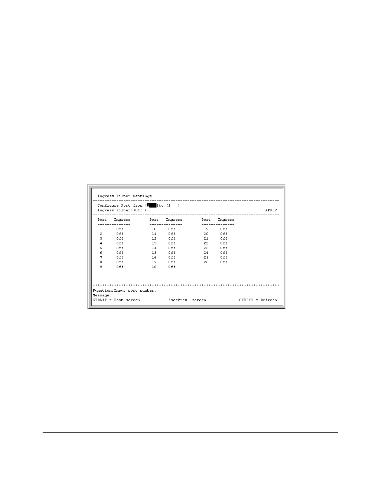
Enabling Ingress Filtering on a Per Port Basis
If ingress filtering is enabled for a port, the interconnect switch will examine the VLAN
information in the packet header (if present) and decide whether or not to forward the packet.
The VID should match the PVID of that port, otherwise, that incoming packet is discarded.
If the packet is tagged with VLAN information, the ingress port will first determine if the
ingress port itself is a member of the tagged VLAN.
• • If the ingress port is not a member of the tagged VLAN, the packet is dropped.
If the ingress port is a member of the 802.1Q VLAN, the interconnect switch then
determines if the destination port is a member of the 802.1Q VLAN, the packet is
forwarded and the destination port transmits it to its attached network segment.
2-30 HP ProLiant BL e-Class C-GbE Interconnect Switch Menu-driven Interface Reference Guide
HP CONFIDENTIAL Codename: DeLorean Part Number: 322858-001 Last Saved On: 2/4/03 11:56 AM
Page 41
Configuring the Switch Modules using the Menu-driven Interface
If the packet is not tagged with VLAN information, the ingress port tags the packet with its
own PVID as a VID (if the port is a tagging port). The interconnect switch then determines if
the destination port is a member of the same VLAN (has the same VID) as the ingress port.
• • If the destination port is not a member of the same VLAN, the packet is dropped.
If the destination port is a member of the same VLAN, the packet is forwarded and the
destination port transmits it on its attached network segment.
Ingress filtering is used to conserve bandwidth within the interconnect switch by dropping
packets that are not on the same VLAN as the ingress port at the point of reception. This
eliminates the subsequent processing of packets that will just be dropped by the destination
port.
To set ingress filtering on a port:
1. Highlight Configure Port Ingress Filter on the IEEE 802.1Q VLANs
Configuration menu.
2. Press the Enter key. The following screen is displayed.
3. Type the range of port numbers you want to configure in the Configure Port field.
4. Toggle between On and Off in the Ingress Filter field.
An ingress filter enables the port to compare the VID tag of an incoming packet with the
PVID number assigned to the port. If the two are different, the port filters (drops) the
packet.
5. Highlight APPLY.
6. Press the Enter key.
IMPORTANT: To save the configuration settings permanently, you must enter them into NVRAM
using the Save Changes option on the main menu. Refer to the “Saving Changes” section earlier
in this chapter.
HP ProLiant BL e-Class C-GbE Interconnect Switch Menu-driven Interface Reference Guide 2-31
HP CONFIDENTIAL Codename: DeLorean Part Number: 322858-001 Last Saved On: 2/4/03 11:56 AM
Page 42
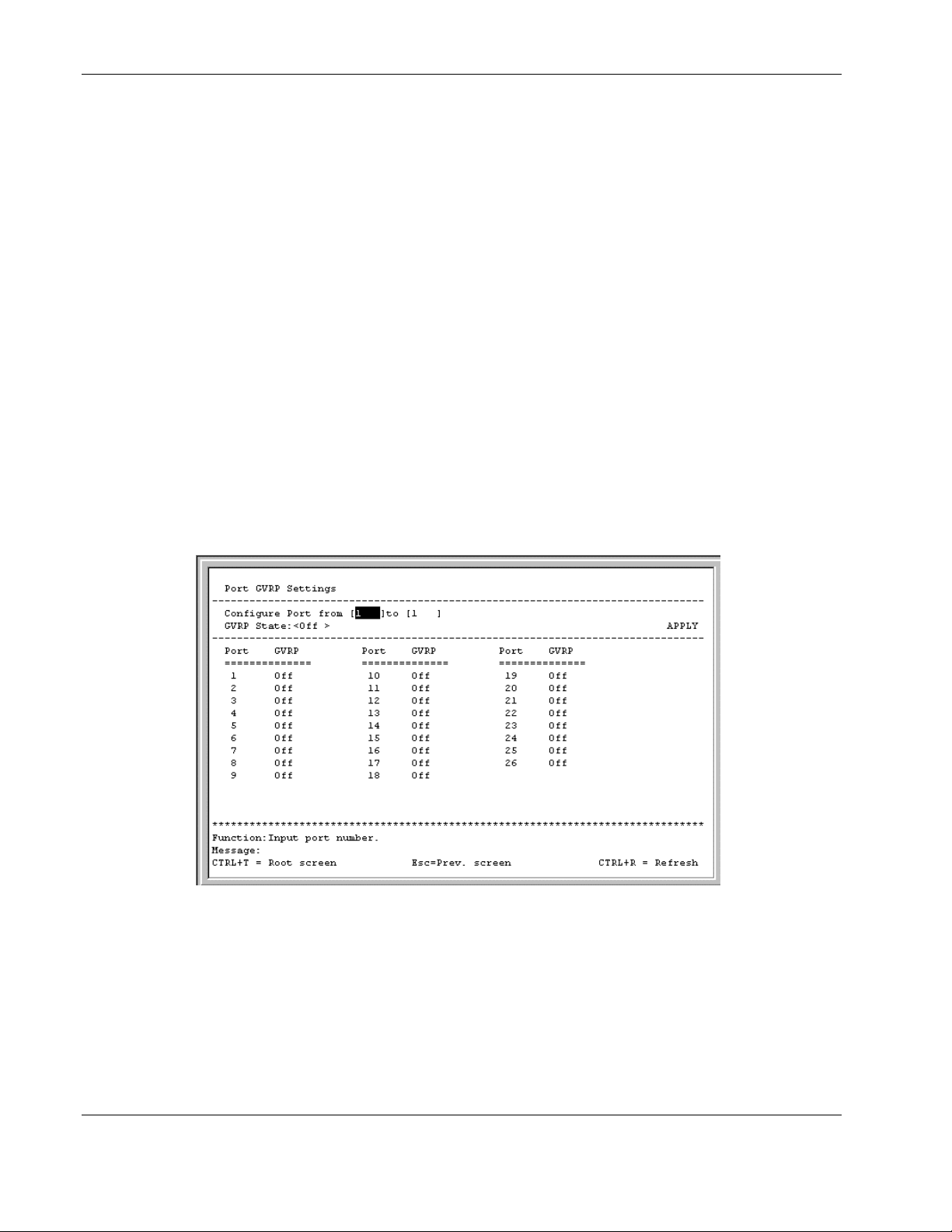
Configuring the Switch Modules using the Menu-driven Interface
Configuring GVRP
This section describes how to configure GVRP on a per port basis. For information on how to
set GVRP globally on the switch module, refer to the “Configuring Advanced Switch Module
Features” section earlier in this chapter.
GARP VLAN Registration Protocol (GVRP) is a Generic Attribute Registration Protocol
(GARP) application that provides 802.1Q-compliant VLAN pruning and dynamic VLAN
creation on 802.1Q trunk ports. With GVRP, the switch module can exchange VLAN
configuration information with other GVRP switches, prune unnecessary broadcast and
unknown unicast traffic, and dynamically create and manage VLANs on switches connected
through 802.1Q trunk ports.
GVRP updates dynamic VLAN registration entries and communicates the new VLAN
information across the network. This feature allows stations to physically move to other
switch module ports and keep their original VLAN settings, without having to reconfigure.
To enable a port to dynamically become a member of a VLAN:
1. Highlight Configure Port GVRP Settings on the IEEE 802.1Q VLANs
Configuration menu.
2. Press the Enter key. The following screen is displayed.
3. Type the range of ports to be configured in the Configure Port fields.
4. Toggle the GVRP State to On.
5. Highlight APPLY.
6. Press the Enter key.
IMPORTANT: To save the configuration settings permanently, you must enter them into NVRAM
using the Save Changes option on the main menu. Refer to the “Saving Changes” section earlier
in this chapter.
2-32 HP ProLiant BL e-Class C-GbE Interconnect Switch Menu-driven Interface Reference Guide
HP CONFIDENTIAL Codename: DeLorean Part Number: 322858-001 Last Saved On: 2/4/03 11:56 AM
Page 43

Configuring IGMP Snooping
This section describes how to configure IGMP snooping on a VLAN ID. For information on
how to set IGMP globally on the switch module and how to setting the IGMP filter mode for
processing multicast packets, refer to the “Configuring Advanced Switch Module Features”
section earlier in this chapter.
Internet Group Management Protocol (IGMP) snooping, when enabled and configured
properly, manages multicast traffic through a switch module. IP multicast traffic is forwarded
based on multicast group membership information registered by the switch module. The
switch module can use IGMP snooping to configure ports dynamically, so that IP multicast
traffic is forwarded only to those ports associated with IP multicast hosts, based on
membership information.
IGMP snooping allows the switch module to recognize IGMP queries and reports sent
between network stations or devices and an IGMP host that belongs to a specific multicast
group. When enabled for IGMP snooping, the switch module can open or close a port to a
specific device based on IGMP messages passing through the module. This feature further
limits unnecessary broadcasts. The switch module can be configured to make queries using
either IGMP version 1 or version 2.
Configuring the Switch Modules using the Menu-driven Interface
When IGMP snooping is enabled globally on the switch module, you can enable or disable
individual VLANs for IGMP snooping.
When IGMP snooping is enabled, any port receiving IGMP response packets will forward
them to the CPU, and the CPU sets this port as a member of the corresponding multicast
address.
The switch module supports three multicast group address filtering modes for making
forwarding decisions regarding multicast packets.
•
Forward all group addresses—All multicast packets destined for all group MAC
addresses are forwarded according to the VLAN rules.
•
Forward all unregistered group addresses—All multicast packets with group MAC
address registration entries existing in the multicast table (both static multicast and group
multicast created by IGMP snooping) are forwarded to member ports. If the group MAC
address does not exist in the multicast table, packets are forwarded according to the
VLAN rules.
•
Filter all unregistered group addresses—All multicast packets with group MAC
addresses are forwarded only if such forwarding is explicitly permitted by a group
address entry in the multicast table. If the group MAC address exists in the multicast
table, then the packets are forwarded using the port member list for that entry. If the
group MAC address does not exist in the multicast table, the packets are dropped.
To configure IGMP Snooping:
1. Highlight Configure IGMP Snooping on the Configuration menu.
2. Press the Enter key. The following screen is displayed.
HP ProLiant BL e-Class C-GbE Interconnect Switch Menu-driven Interface Reference Guide 2-33
HP CONFIDENTIAL Codename: DeLorean Part Number: 322858-001 Last Saved On: 2/4/03 11:56 AM
Page 44
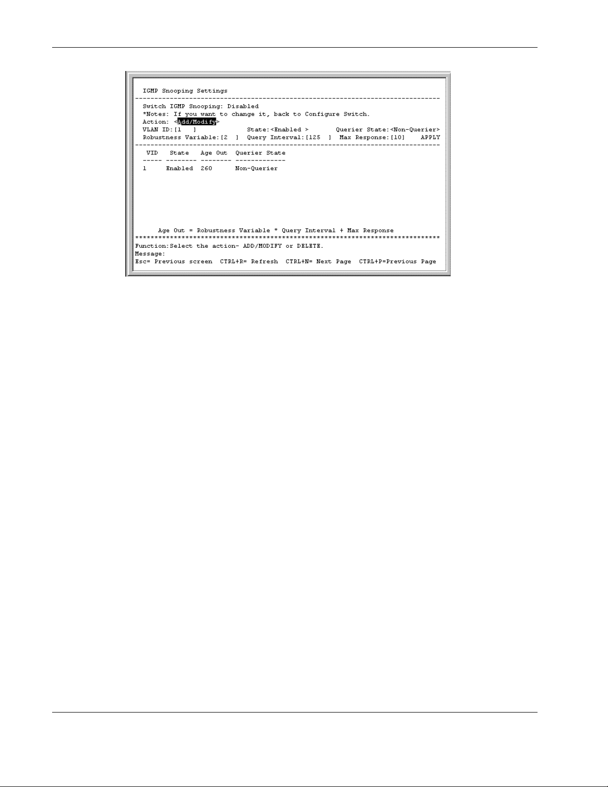
Configuring the Switch Modules using the Menu-driven Interface
The top line displays if IGMP Snooping is enabled or disabled globally on the switch
module.
If IGMP Snooping is enabled, you can set the following:
— Action—Toggle to Add/Modify.
— VLAN ID—Type the VLAN ID on which you want to enable IGMP snooping.
— State—Toggle to Enabled to enable IGMP snooping on the VLAN.
— Querier State—Toggle between Non-Querier, V1-Querier, and V2-Querier. This
setting is used to specify the IGMP version (1 or 2) that is used by the IGMP
interface when making queries.
— Robustness Variable—Enter a value between 2 and 255, with larger values being
specified for subnetworks that are expected to lose larger numbers of packets.
— Query Interval—Enter a value between 1 and 65,500 seconds, with a default of
125 seconds. This setting specifies the length of time between sending IGMP queries.
— Max Response—Set the maximum amount of time allowed before sending an IGMP
response report. A value between 1 and 25 seconds can be entered; the default is
10 seconds.
3. After making your changes, highlight APPLY, then press the Enter key.
IMPORTANT: To save the configuration settings permanently, you must enter them into NVRAM
using the Save Changes option on the main menu. Refer to the “Saving Changes” section earlier
in this chapter.
2-34 HP ProLiant BL e-Class C-GbE Interconnect Switch Menu-driven Interface Reference Guide
HP CONFIDENTIAL Codename: DeLorean Part Number: 322858-001 Last Saved On: 2/4/03 11:56 AM
Page 45

Configuring Port Trunking
This section describes how to configure port trunking. For information on how to set the
trunk load sharing algorithm parameter, refer to the “Configuring Advanced Switch Module
Features” section earlier in this chapter.
Port trunking allows several ports to be grouped together to act as a single link. This provides
a bandwidth that is a multiple of a single link bandwidth. Port trunking is most commonly
used to link a bandwidth-intensive network device or devices, such as a server, to the
backbone of a network.
The switch module allows the creation of up to six port trunk groups, each group consisting
of up to eight links (ports). HP recommends that the port trunk ports be members of the same
VLAN. Only similar type ports can be members of port trunks. A combination of Fast
Ethernet (FE) and Gigabit (GE) ports cannot be members of the same port trunk.
The configuration of the lowest numbered port in the group becomes the configuration for all
of the ports in the trunk group. This port is called the master port of the trunk group, and all
configuration options, including the VLAN configuration, which can be applied to the master
port, are applied to the entire port trunking group.
Configuring the Switch Modules using the Menu-driven Interface
Load balancing is automatically applied to the ports in the trunked group, based on the setting
of the trunk load-sharing algorithm, and a link failure within the group causes the network
traffic to be directed to the remaining links in the group.
Spanning Tree Protocol treats a port trunking group as a single link on the switch module
level. STP uses the port parameters of the master port in the calculation of port cost and in
determining the state of the port trunking group. If two redundant port trunking groups are
configured on the switch module, STP blocks one entire group, similar to STP blocking a link
in case of two redundant links.
Considerations when Creating a Port Trunking Group
When creating a port trunking group, consider the following rules that determine how the port
trunk reacts in network topology:
•
The first port of the port trunk is implicitly configured to be the master logical port. This
is the reference port used in configuration commands. It can be thought of as the logical
port representing the entire group.
•
When using a port trunk, always reference the master logical port of the group when
configuring or viewing VLANs.
•
VLANs configured to use other ports in the port trunk will have those ports deleted from
the VLAN when the port trunk becomes enabled.
•
The Spanning Tree algorithm views port trunk as a single Spanning Tree port. The
Spanning Tree port is represented by the master logical port.
•
If the VLAN settings of the master logical port are changed, the VLAN settings of all
members of that port trunk are changed similarly.
HP ProLiant BL e-Class C-GbE Interconnect Switch Menu-driven Interface Reference Guide 2-35
HP CONFIDENTIAL Codename: DeLorean Part Number: 322858-001 Last Saved On: 2/4/03 11:56 AM
Page 46
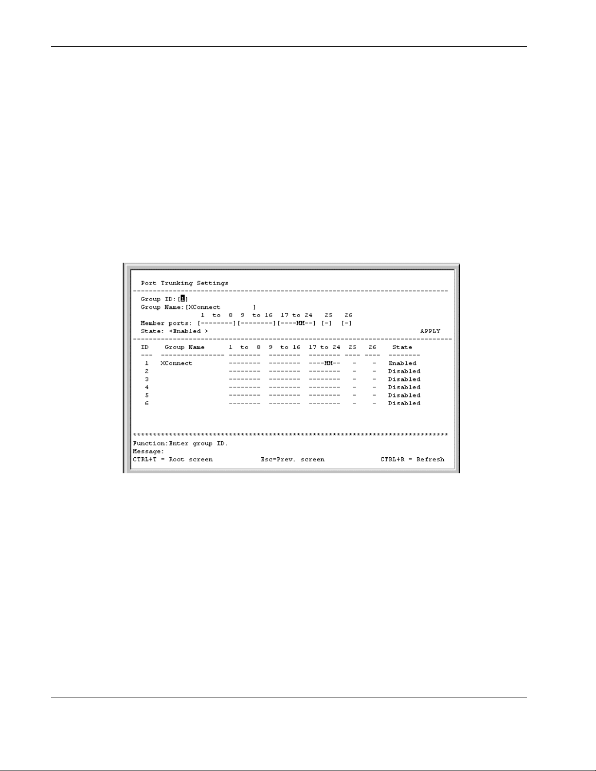
Configuring the Switch Modules using the Menu-driven Interface
• If the IGMP snooping configuration for any port trunk member is changed, the IGMP
snooping settings for all port trunk members are changed.
• • The port trunk takes precedence over any other setting. That is, the settings of trunked
ports are the same as the master port settings.
When any trunked port becomes a non-trunked port, all of the port configurations are
reset to default settings.
Refer to Appendix G in the HP ProLiant e-Class C-GbE Interconnect Switch User Guide for
additional information on port trunking.
To configure a port trunking group:
1. Highlight Configure Port Trunking on the Configuration menu.
2. Press the Enter key. The following screen is displayed.
The user-changeable parameters in the switch module are as follows:
— Group ID—This field is for a group ID number for the port trunking group.
— Group Name—Enter a name for the port trunking group.
— Member ports—Toggle between M to indicate membership of the port trunking
group, or a dash (—) to indicate nonmembership.
— State—Toggle between Enabled and Disabled. This setting is used to turn a port
trunking group on or off. It is useful for diagnostics, to quickly isolate a bandwidth
intensive network device or to have an absolute backup aggregation group that is not
under automatic control.
3. After making your changes, highlight APPLY, then press the Enter key.
IMPORTANT: To save the configuration settings permanently, you must enter them into NVRAM
using the Save Changes option on the main menu. Refer to the “Saving Changes” section earlier
in this chapter.
2-36 HP ProLiant BL e-Class C-GbE Interconnect Switch Menu-driven Interface Reference Guide
HP CONFIDENTIAL Codename: DeLorean Part Number: 322858-001 Last Saved On: 2/4/03 11:56 AM
Page 47
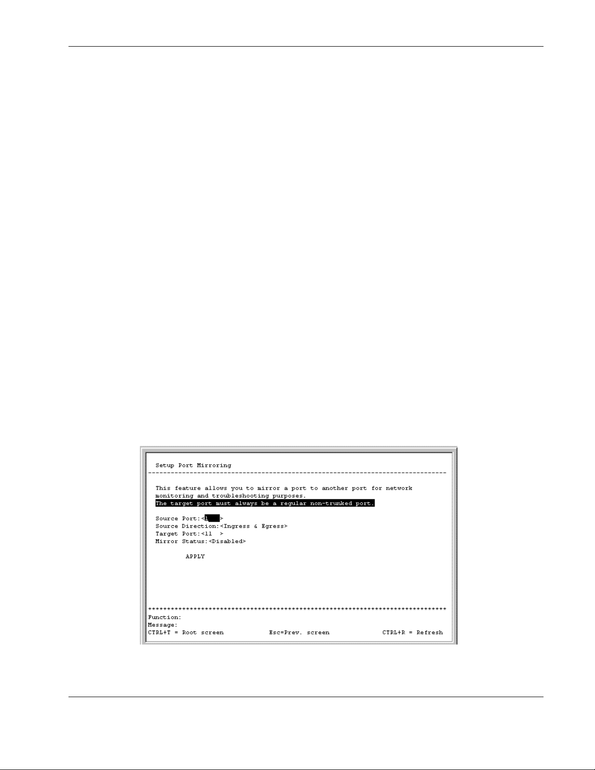
Configuring Port Mirroring
The switch module allows you to copy frames transmitted and received on a port (source) and
redirect the copies to another port (target). You can attach a monitoring device to the
mirrored (target) port, such as a sniffer or an RMON probe, to view details about the packets
passing through the source port. This setting is useful for network monitoring and
troubleshooting purposes.
The following configuration rules apply to any port mirroring configuration:
•
A target mirror port cannot be configured as a trunk member.
•
VLAN configuration settings for any ports configured for mirroring cannot be changed.
•
The source and target ports should be members of the same VLAN.
The direction of traffic on the source port can be one of the following:
•
Ingress traffic (received packets) on the source port
•
Egress traffic (transmitted packets) on the source port
•
Ingress and egress traffic on the source port
IMPORTANT: You cannot mirror a fast port onto a slower port. For example, if you try to mirror the
traffic from a 100-Mb/s port onto a 10-Mb/s port, you can cause throughput problems. The port from
which you are copying frames should always support an equal or lower speed than the port to which
you are sending the copies. Also, the target port cannot be a member of a trunk group.
Configuring the Switch Modules using the Menu-driven Interface
To configure port mirroring:
1. Highlight Configure Port Mirroring on the Configuration menu.
2. Press the Enter key. The following screen is displayed.
3. In the Source Port field, toggle to the number of the port from which you want to copy
frames.
HP ProLiant BL e-Class C-GbE Interconnect Switch Menu-driven Interface Reference Guide 2-37
HP CONFIDENTIAL Codename: DeLorean Part Number: 322858-001 Last Saved On: 2/4/03 11:56 AM
Page 48
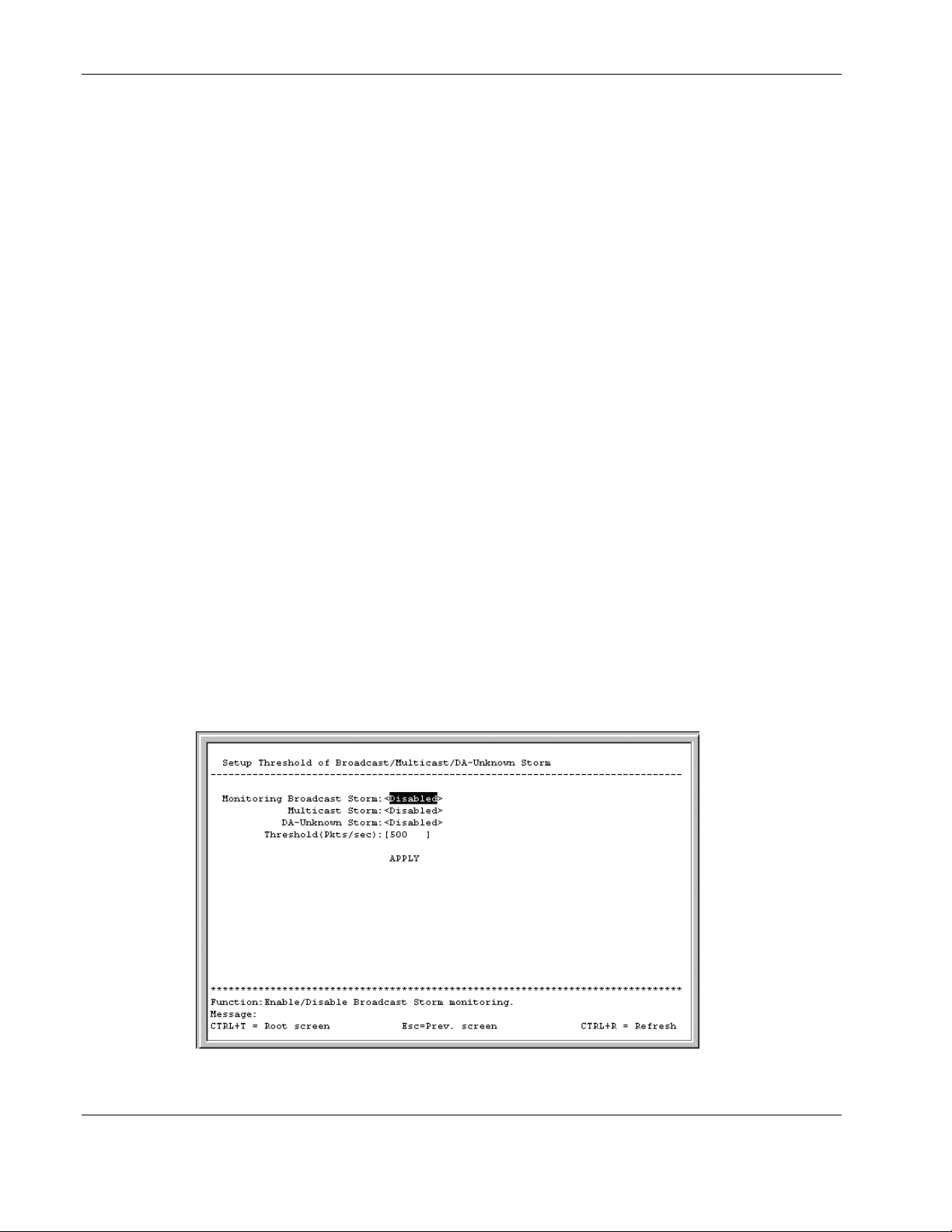
Configuring the Switch Modules using the Menu-driven Interface
4. In the Source Direction field, toggle to the desired direction: Ingress, Egress, or Ingress
& Egress.
5. In the Target Port field, toggle to the port that receives the copies from the source port.
The target port is where you connect a monitoring or troubleshooting device such as a
sniffer or an RMON probe.
6. Toggle the Mirror Status field to Enabled.
7. Highlight APPLY.
8. Press the Enter key.
IMPORTANT: To save the configuration settings permanently, you must enter them into NVRAM
using the Save Changes option on the main menu. Refer to the “Saving Changes” section earlier
in this chapter.
Configuring Thresholds for Broadcast, Multicast, Unknown Storm Prevention or Monitoring
The switch module allows you to set the threshold (in packets per second) for three types of
storms: broadcast, multicast, and one where the packet destination address (DA) is unknown.
The higher the threshold, the more packets the switch module can accept per second. If the
threshold is exceeded, any additional packets received are dropped. Entering a low value
means packets have a greater chance to exceed the threshold and be dropped from the switch
module.
To configure the threshold of a broadcast, multicast, unknown storm:
1. Highlight Configure Threshold of Broadcast/Multicast/DA-Unknown Storm on the
Configuration menu.
2. Press the Enter key. The following screen is displayed.
3. Toggle the desired storm option to Enabled. Leave the other two options Disabled.
2-38 HP ProLiant BL e-Class C-GbE Interconnect Switch Menu-driven Interface Reference Guide
HP CONFIDENTIAL Codename: DeLorean Part Number: 322858-001 Last Saved On: 2/4/03 11:56 AM
Page 49
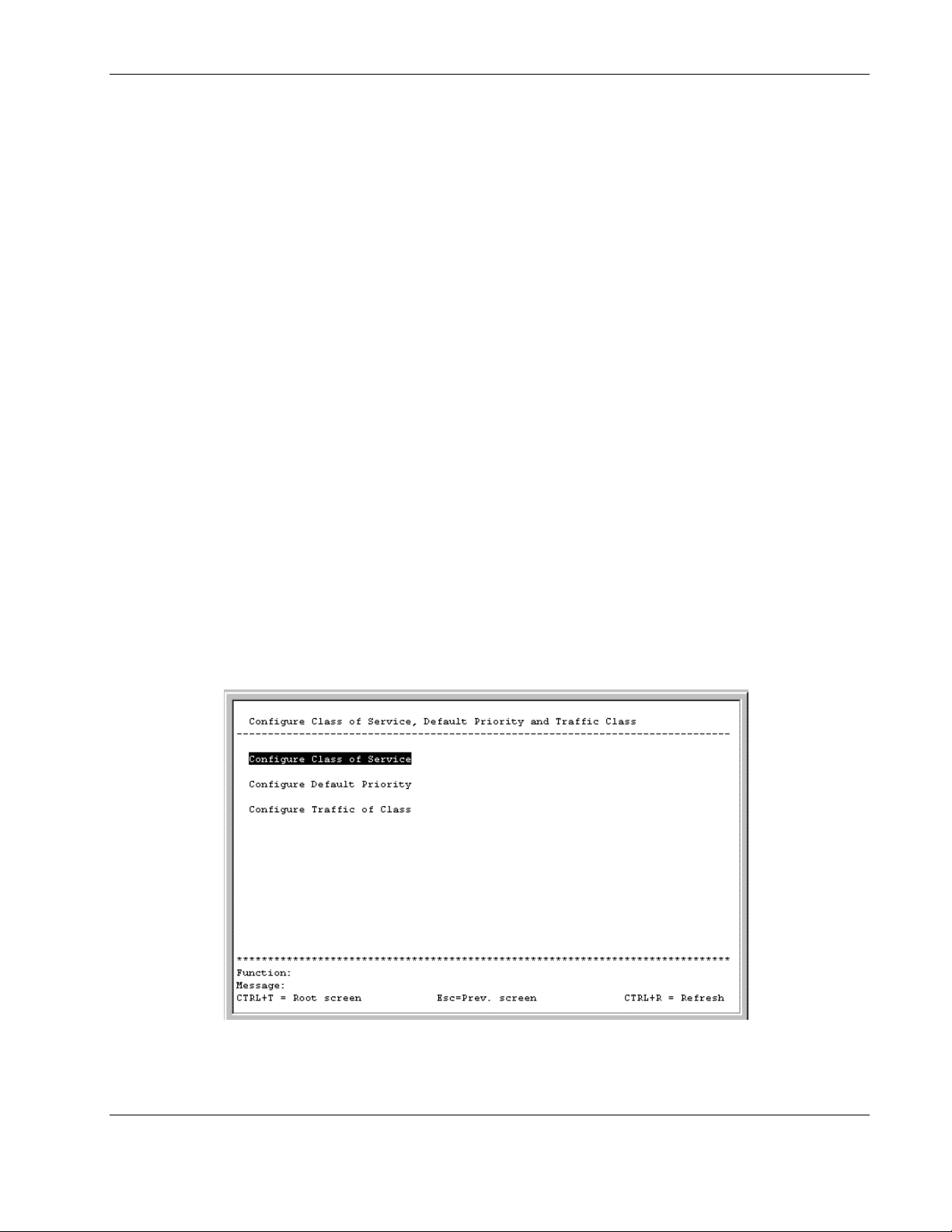
Configuring the Switch Modules using the Menu-driven Interface
4. Type a threshold in the Threshold (Pkts/sec) field.
5. Highlight APPLY.
6. Press the Enter key.
IMPORTANT: To save the configuration settings permanently, you must enter them into NVRAM
using the Save Changes option on the main menu. Refer to the “Saving Changes” section earlier
in this chapter.
Configuring Class of Service, Default Port Priority, and Traffic Class
This section describes how to configure class of service, default port priority, and traffic
class. For information on how to set the class of service queue options, refer to the
“Configuring Advanced Switch Module Features” section earlier in this chapter.
Class of Service (CoS) for packet prioritization allows you to set priority levels on the switch
module for forwarding packets based on the priority setting information in the packets. The
switch module supports four classes (0-3) of traffic (buffers or queues) for implementing
priority and allows eight priority levels (0-7) to be mapped to the four classes. Traffic from a
specific server port can be given priority over packets from other devices according to the
range of priority levels.
To configure Class of Service, default priority, and traffic class:
1. Highlight Configure Class of Service, Default Priority, and Traffic Class on the
Configuration menu.
2. Press the Enter key. The following screen is displayed.
HP ProLiant BL e-Class C-GbE Interconnect Switch Menu-driven Interface Reference Guide 2-39
HP CONFIDENTIAL Codename: DeLorean Part Number: 322858-001 Last Saved On: 2/4/03 11:56 AM
Page 50
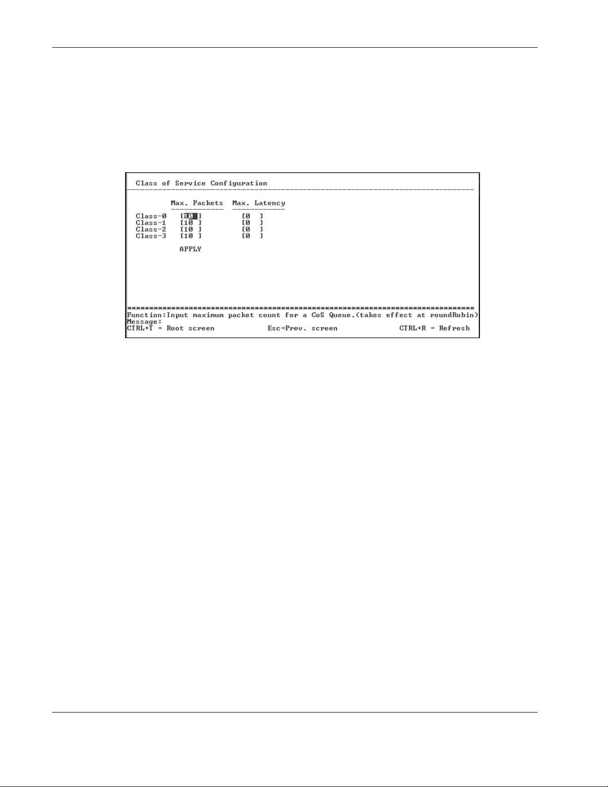
Configuring the Switch Modules using the Menu-driven Interface
Setting Class of Service
To configure Class of Service:
1. Highlight Configure Class of Service on the Configure Class of Service, Default
Priority, and Traffic Class menu.
2. Press the Enter key. The following screen is displayed.
This screen allows you to set the following features:
— Max. Packets—The Class of Service scheduling algorithm starts from the highest
CoS for a given port, sends the maximum number of packets, then moves on to the
next lower CoS. Values from 0 to 255 can be entered in this field. Entering zero
instructs the switch module to continue processing packets until there are no more
packets in the CoS transaction queue.
— Max. Latency—The maximum latency is the maximum allowable time a packet
stays in the CoS queue. The packets in this queue are not delayed more than the
amount entered in this field. The timer is disabled when this field is set to zero. Each
unit of this timer is equal to 16 microseconds.
3. After making your changes, highlight APPLY and then press the Enter key.
IMPORTANT: To save the configuration settings permanently, you must enter them into NVRAM
using the Save Changes option on the main menu. Refer to the “Saving Changes” section earlier
in this chapter.
2-40 HP ProLiant BL e-Class C-GbE Interconnect Switch Menu-driven Interface Reference Guide
HP CONFIDENTIAL Codename: DeLorean Part Number: 322858-001 Last Saved On: 2/4/03 11:56 AM
Page 51
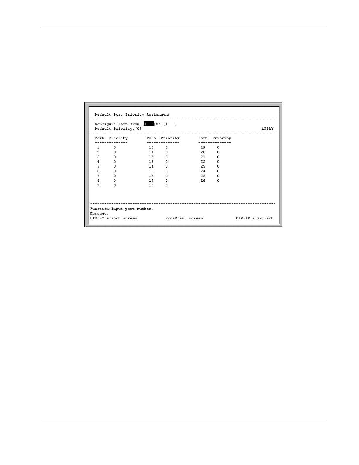
Setting Port Priority
To assign port default priority:
1. Highlight Configure Default Priority on the Configure Class of Service, Default
Priority, and Traffic Class menu.
2. Press the Enter key. The following screen is displayed.
Configuring the Switch Modules using the Menu-driven Interface
3. Type the port range in the Configure Port fields.
4. Type the port priority in the Default Priority field.
5. Highlight APPLY.
6. Press the Enter key.
IMPORTANT: To save the configuration settings permanently, you must enter them into NVRAM
using the Save Changes option on the main menu. Refer to the “Saving Changes” section earlier
in this chapter.
HP ProLiant BL e-Class C-GbE Interconnect Switch Menu-driven Interface Reference Guide 2-41
HP CONFIDENTIAL Codename: DeLorean Part Number: 322858-001 Last Saved On: 2/4/03 11:56 AM
Page 52
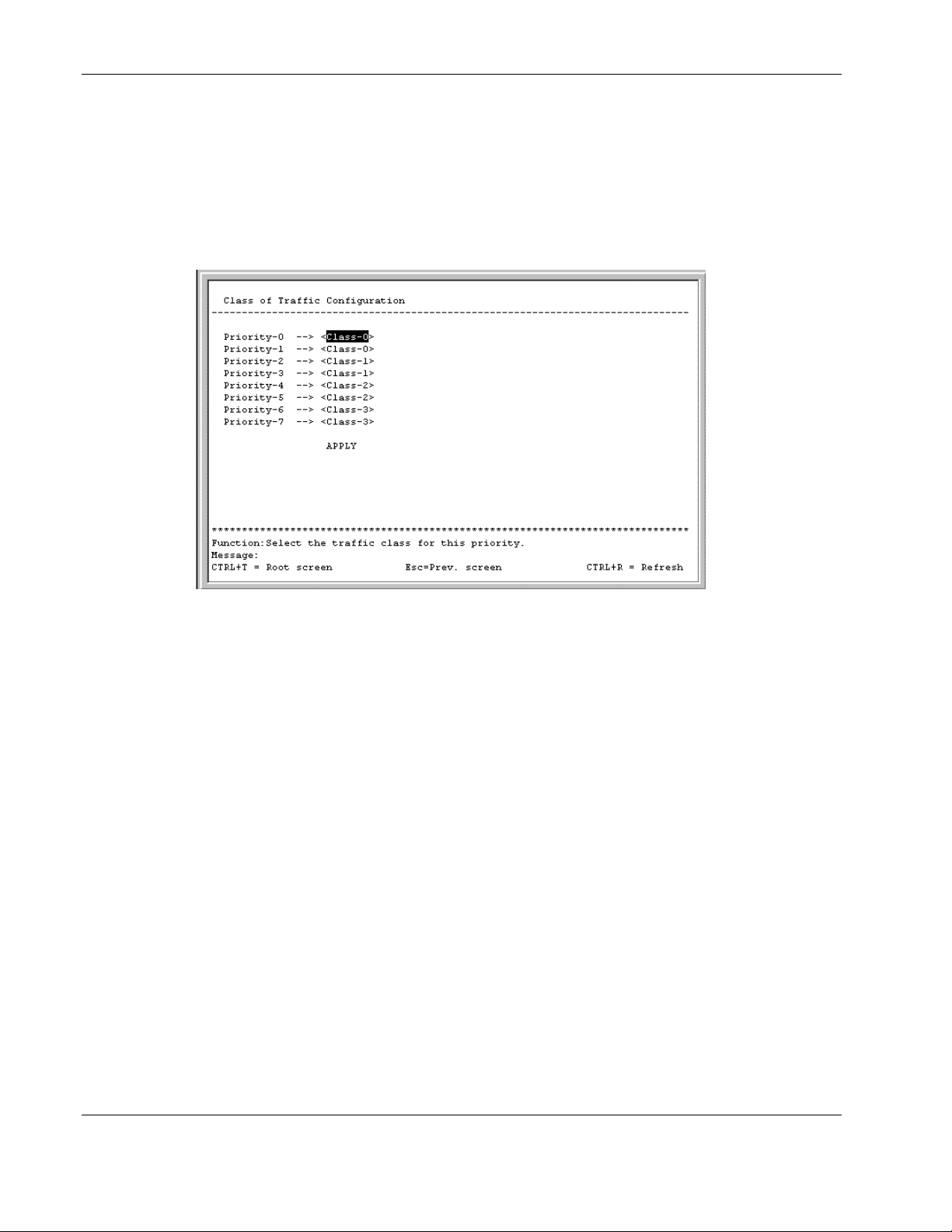
Configuring the Switch Modules using the Menu-driven Interface
Setting Traffic Class
To configure traffic class:
1. Highlight Configure Traffic of Class on the Configure Class of Service, Default
Priority, and Traffic Class menu.
2. Press the Enter key. The following screen is displayed.
3. Toggle the Priority fields to set the traffic class for the eight levels of priority for the
switch module. Class values are from 0 to 3.
4. Highlight APPLY.
5. Press the Enter key.
IMPORTANT: To save the configuration settings permanently, you must enter them into NVRAM
using the Save Changes option on the main menu. Refer to the “Saving Changes” section earlier
in this chapter.
2-42 HP ProLiant BL e-Class C-GbE Interconnect Switch Menu-driven Interface Reference Guide
HP CONFIDENTIAL Codename: DeLorean Part Number: 322858-001 Last Saved On: 2/4/03 11:56 AM
Page 53
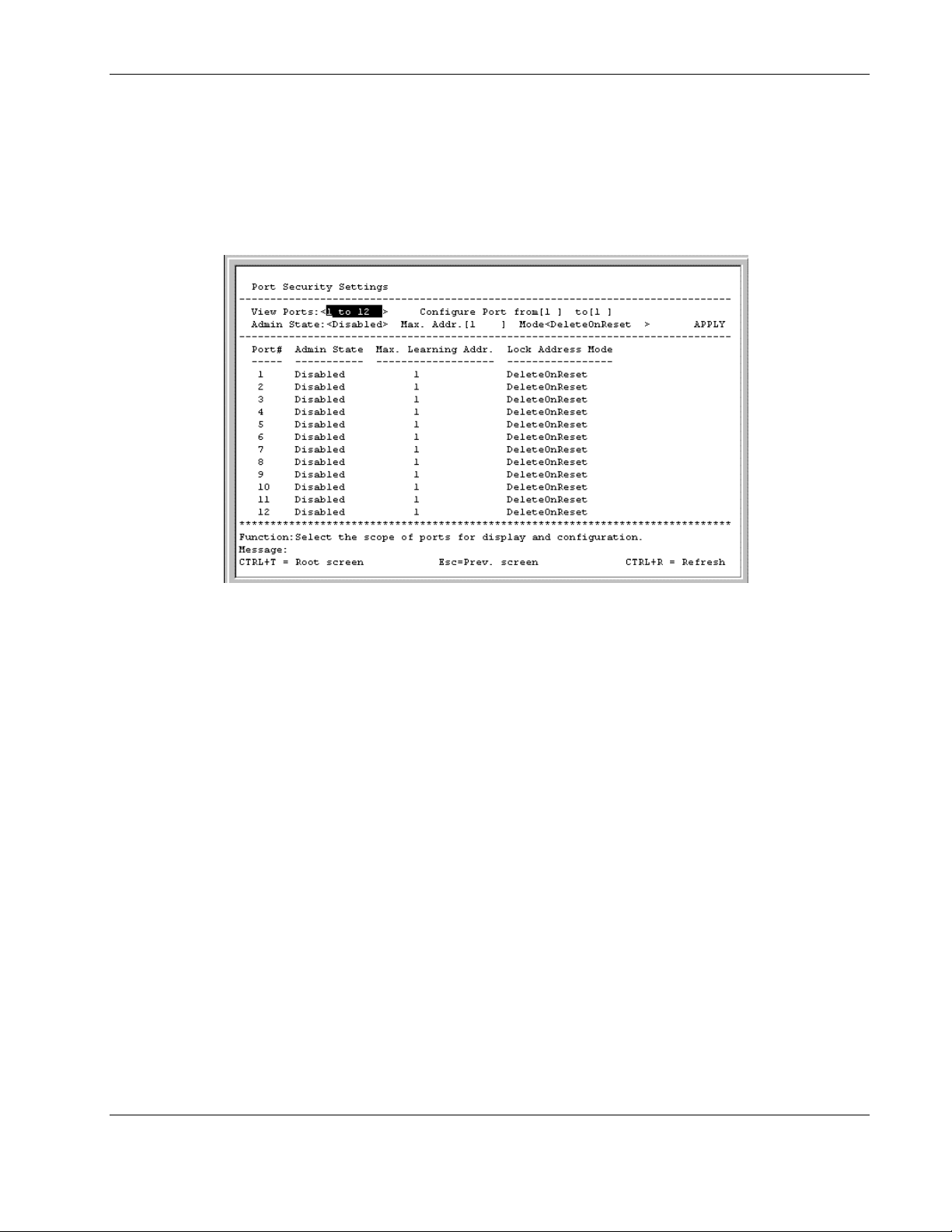
Configuring Port Security
To configure security for a specified port or range of ports on the switch module:
1. Highlight Configure Port Security on the Configuration menu.
2. Press the Enter key. The following screen is displayed.
Configuring the Switch Modules using the Menu-driven Interface
3. Toggle the View Ports field to the port range that you want to view.
4. Type the port number or range of numbers to configure in the Configure Port fields.
5. Toggle the Admin State field to Enabled to enable port security on the ports.
6. Type a number between 1 and 10 in the Max. Addr. field to set the maximum number of
addresses that can be learned.
7. Toggle to the mode that you want in the Mode field: DeleteOnReset or
DeleteOnTimeout.
8. Highlight APPLY.
9. Press the Enter key.
IMPORTANT: To save the configuration settings permanently, you must enter them into NVRAM
using the Save Changes option on the main menu. Refer to the “Saving Changes” section earlier
in this chapter.
HP ProLiant BL e-Class C-GbE Interconnect Switch Menu-driven Interface Reference Guide 2-43
HP CONFIDENTIAL Codename: DeLorean Part Number: 322858-001 Last Saved On: 2/4/03 11:56 AM
Page 54
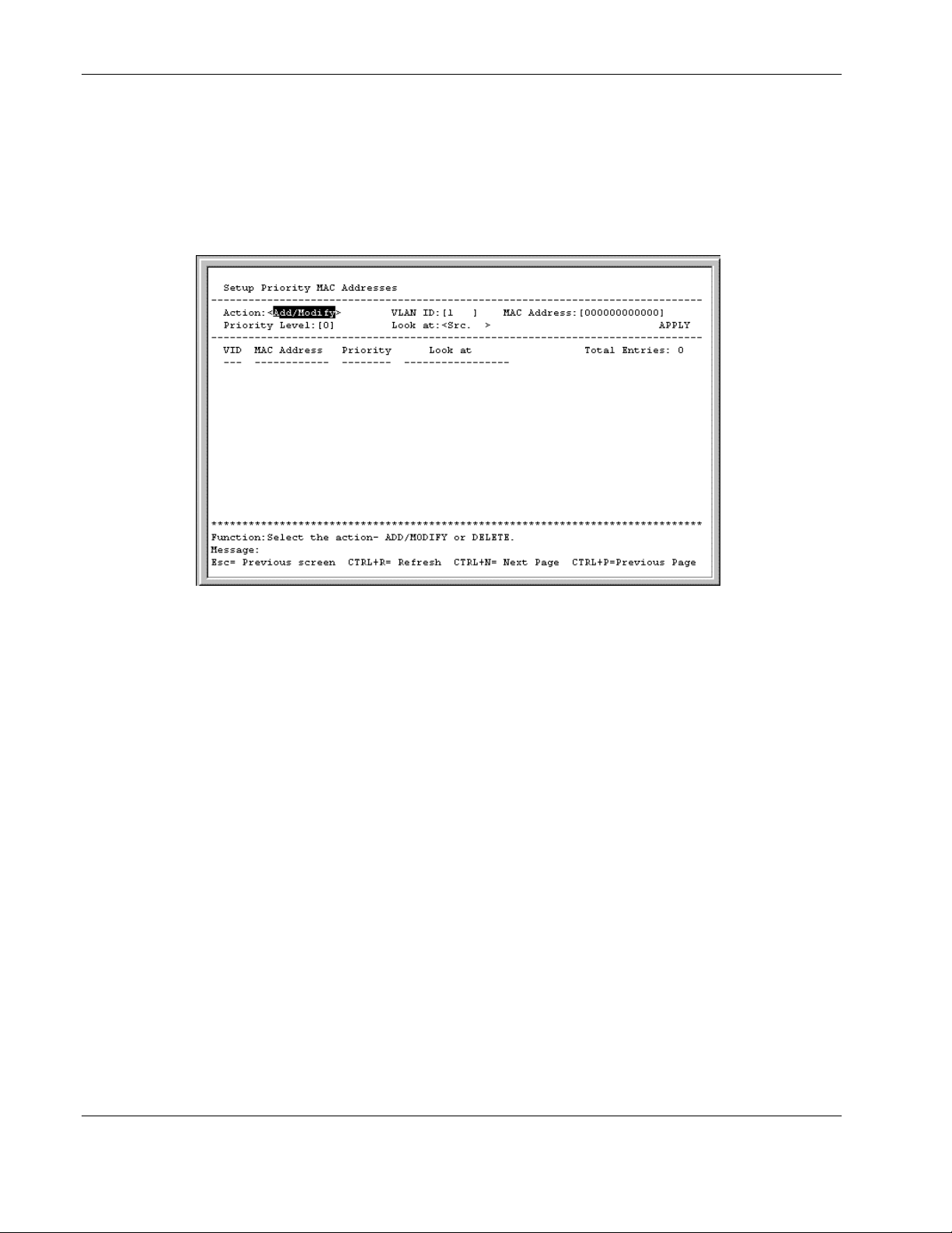
Configuring the Switch Modules using the Menu-driven Interface
Configuring Priority MAC Addresses
To configure priority MAC address for a specified VLAN on the switch module:
1. Highlight Configure Priority MAC Addresses on the Configuration menu.
2. Press the Enter key. The following screen is displayed.
3. Toggle to Add/Modify in the Action field.
4. Type the VLAN ID in the VLAN ID field.
5. Type the MAC address for which priority on the switch module is to be established in the
MAC Address field.
6. Type the priority level for the MAC address in the Priority Level field. The range is
from 0 to 7, with 0 being the highest priority.
7. Select the state under which the above priority will be active in the Look at field. The
options are:
— Dst.Addr—Packets with the selected MAC address as their destination will be given
the selected priority.
— Src.Addr—Packets with the selected MAC address as their source will be given the
selected priority.
— Either—All packets with the selected MAC address will be given the selected
priority.
8. Highlight APPLY.
9. Press the Enter key.
IMPORTANT: To save the configuration settings permanently, you must enter them into nonvolatile RAM (NVRAM) using the Save Changes option on the main menu. Refer to the “Saving
Changes” section earlier in this chapter.
2-44 HP ProLiant BL e-Class C-GbE Interconnect Switch Menu-driven Interface Reference Guide
HP CONFIDENTIAL Codename: DeLorean Part Number: 322858-001 Last Saved On: 2/4/03 11:56 AM
Page 55

Configuring the Switch Modules using the Menu-driven Interface
Configuring the Switch Module Date and Time
The switch module can maintain the current date and time. This information displays on the
management interfaces and is used to record the date and time of interconnect switch events
in the history log.
When a new switch module is first booted up, the firmware clock starts at zero (0) and counts
the seconds since bootup. In order for the clock to display the real date and time, you must
either
•
Manually set the date and time on the interconnect switch, or
•
Enable Simple Network Time Protocol (SNTP) on the switch module, and then set the
SNTP parameters.
SNTP allows the switch to synchronize its real time to the network time. When SNTP is
enabled, the switch module sends a request to a primary SNTP server in each period of a
specified polling interval asking for the Greenwich Mean Time (GMT). If the primary SNTP
server is not available, the request is sent to a secondary SNTP server.
When SNTP is enabled, the following events cause the switch module to request the date and
time through SNTP:
•
The polling interval time expires.
•
Changes are made to the configuration settings for Daylight Saving Time, time zone,
SNTP Server 1 or Server 2, or polling interval.
•
SNTP state is changed from disabled to enabled.
IMPORTANT: If the system clock is set and power is lost to the interconnect switch, manual time
settings are reset to factory defaults when the interconnect switch is powered on. If this occurs,
manually reset the date and time. If SNTP is configured, losing power has no effect, so no manual
resetting of time is required.
HP ProLiant BL e-Class C-GbE Interconnect Switch Menu-driven Interface Reference Guide 2-45
HP CONFIDENTIAL Codename: DeLorean Part Number: 322858-001 Last Saved On: 2/4/03 11:56 AM
Page 56
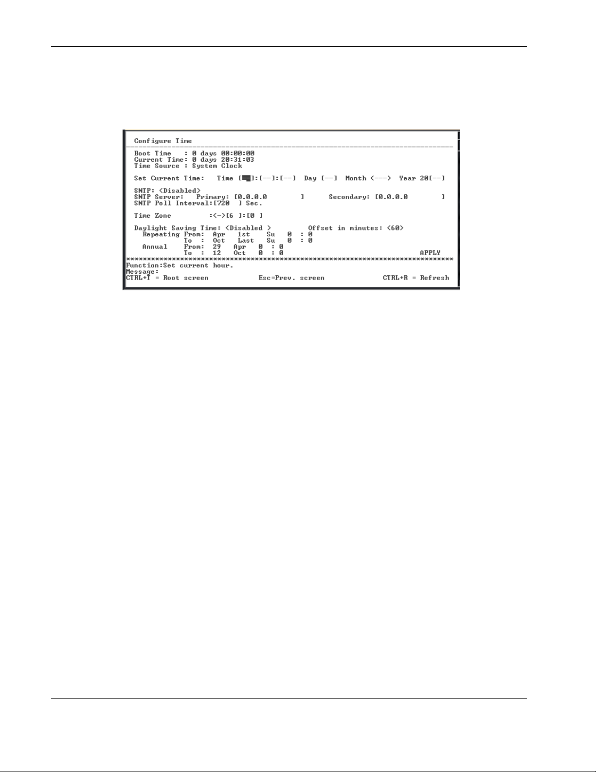
Configuring the Switch Modules using the Menu-driven Interface
To configure time settings:
1. Highlight Configure Time on the Configuration menu.
2. Press the Enter key. The following screen is displayed.
The Configure Time screen allows you to configure the current time and date, enable SNTP,
set the SNTP parameters, and set the parameters for daylight saving time.
The screen displays the following:
— Boot Time—The date and time when the switch module was last rebooted
— Current Time—The current date and time (after they have initially been set or
SNTP configured)
— Time Source—The method in which the switch module gets the current time
information: System Clock, Primary SNTP Server, or Secondary SNTP Server
Complete the following fields to configure the time information:
— Set Current Time—This field will be grayed out when SNTP is enabled. To
manually set the current type, enter the following:
— Time—Type the current time in hh:mm:ss format. Leading zeros (0) are not
required.
— Day—Type the first two letters of the current day of the week: Mo, Tu, We, Th,
Fr, Sa, or Su.
— Month—Select the abbreviation for the current month.
— Year—Type the last two digits of the current year.
— SNTP—Select Disabled or Enabled. The default is Disabled.
— SNTP Server Primary—Type the IP address for the primary SNTP server.
— SNTP Server Secondary—Type the IP address for the secondary SNTP server
— SNTP Poll Interval—Type the polling interval (in seconds) for requesting the
time from the server. A number from 30 to 99999 is allowed. The default is 720.
2-46 HP ProLiant BL e-Class C-GbE Interconnect Switch Menu-driven Interface Reference Guide
HP CONFIDENTIAL Codename: DeLorean Part Number: 322858-001 Last Saved On: 2/4/03 11:56 AM
Page 57

Configuring the Switch Modules using the Menu-driven Interface
— Time Zone—Select + or – to indicate if the time zone is ahead of (+) or behind (-)
the Greenwich Mean Time. Then, type the number of hours and minutes that the time
zone is ahead or behind the Greenwich Mean Time.
— Daylight Saving Time—Select Disabled, Repeating, or Annual to set if and how
daylight saving time will be determined. Repeating allows you to set specific days of
the week and month, for example the first Sunday in April through the fourth Sunday
in October. Annual allows you to set specific dates for the year, for example April 3
through October 27.
— Offset in minutes—Type the number of minutes that the daylight saving time is
offset from the current time. Valid values are 00 to 60.
— Repeating From—Select the starting month, week of the month (1, 2, 3, 4, or
last), and day of the week. Then type the starting hours and minutes.
— Repeating To—Select the ending month, week of the month, and day of the
week. Then type the starting hour and minutes
— Annual From—Type the starting date. Select the starting month. Then type the
starting hour and minutes.
— Annual To—Type the ending date. Select the starting month. Then type the
starting hour and minutes.
3. After making your changes, highlight APPLY then press the Enter key.
IMPORTANT: To save the configuration settings permanently, you must enter them into NVRAM
using the Save Changes option on the main menu. Refer to the “Saving Changes” section earlier
in this chapter.
Monitoring Switch Module Functions
The switch module provides extensive network monitoring capabilities.
To display the network data compiled by the switch module:
1. Highlight Network Monitoring on the main menu.
HP ProLiant BL e-Class C-GbE Interconnect Switch Menu-driven Interface Reference Guide 2-47
HP CONFIDENTIAL Codename: DeLorean Part Number: 322858-001 Last Saved On: 2/4/03 11:56 AM
Page 58
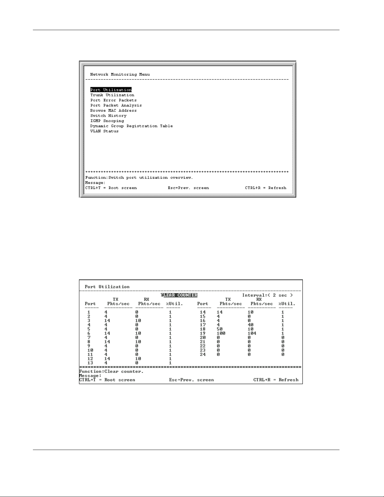
Configuring the Switch Modules using the Menu-driven Interface
2. Press the Enter key. The following screen is displayed.
The Network Monitoring Menu lists the monitoring options for the switch module.
Monitoring Port Utilization
To view the port utilization of all the ports on the switch module:
1. Highlight Port Utilization on the Network Monitoring Menu.
2. Press the Enter key. The following screen is displayed.
The Port Utilization screen shows the number of packets transmitted and received per
second and calculates the percentage of the total available bandwidth being used on the
port (displayed under %Util.).
3. In the Interval field, toggle to select the frequency at which the information on the screen
is refreshed. The default is two seconds.
2-48 HP ProLiant BL e-Class C-GbE Interconnect Switch Menu-driven Interface Reference Guide
HP CONFIDENTIAL Codename: DeLorean Part Number: 322858-001 Last Saved On: 2/4/03 11:56 AM
Page 59
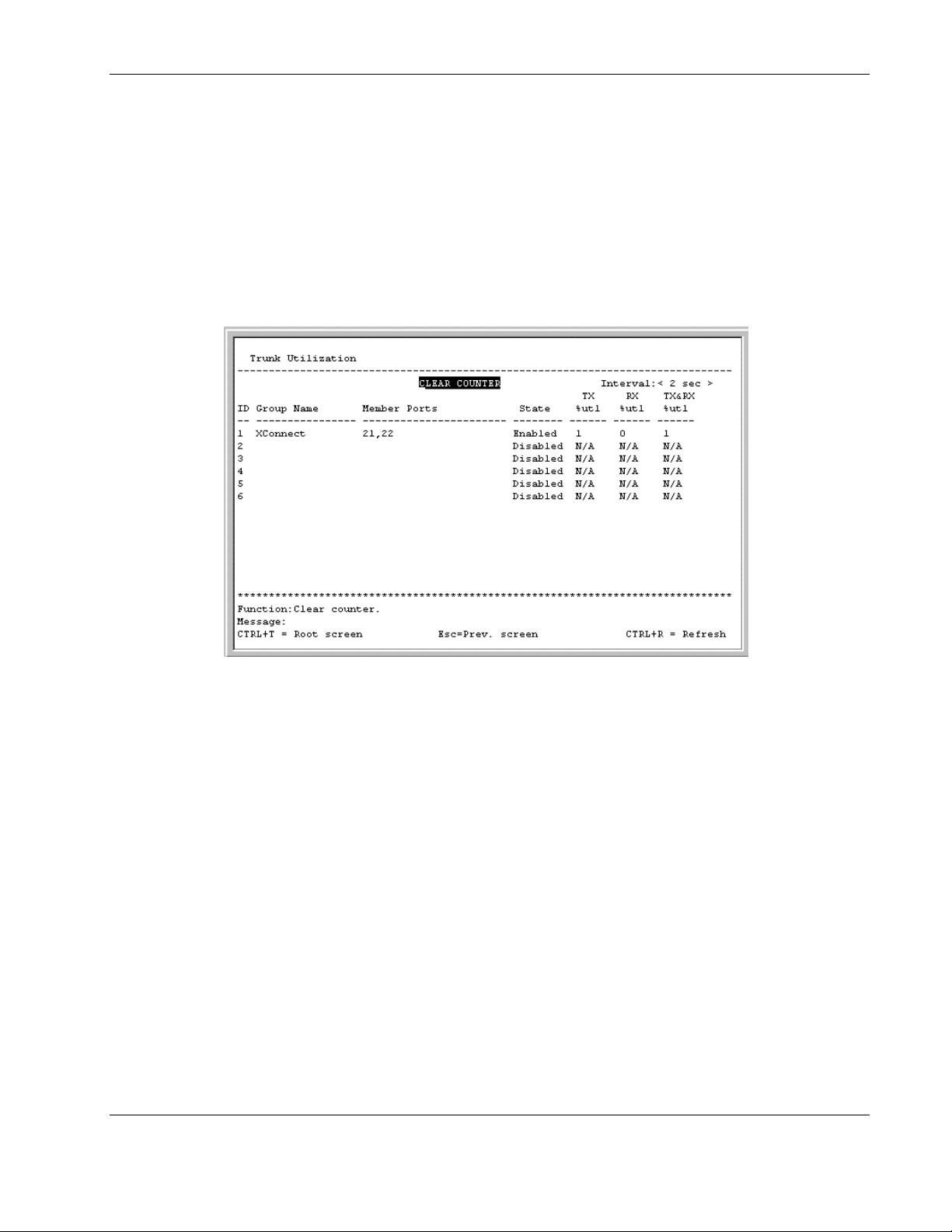
4. To reset the counters, highlight CLEAR COUNTER.
5. Press the Enter key.
Monitoring Trunk Utilization
To view the trunk utilization of all the ports on the switch module:
1. Highlight Trunk Utilization on the Network Monitoring Menu.
2. Press the Enter key. The following screen is displayed.
Configuring the Switch Modules using the Menu-driven Interface
The Trunk Utilization window allows you to view three items for an individual port
trunking group: the percentage of packets transmitted, the percentage of packets being
received per second, and the percentage of total available bandwidth being used by the
group.
3. In the Interval field, toggle to select the frequency at which the information on the screen
is refreshed. The default is two seconds.
4. To reset the counters, highlight CLEAR COUNTER.
5. Press the Enter key.
HP ProLiant BL e-Class C-GbE Interconnect Switch Menu-driven Interface Reference Guide 2-49
HP CONFIDENTIAL Codename: DeLorean Part Number: 322858-001 Last Saved On: 2/4/03 11:56 AM
Page 60
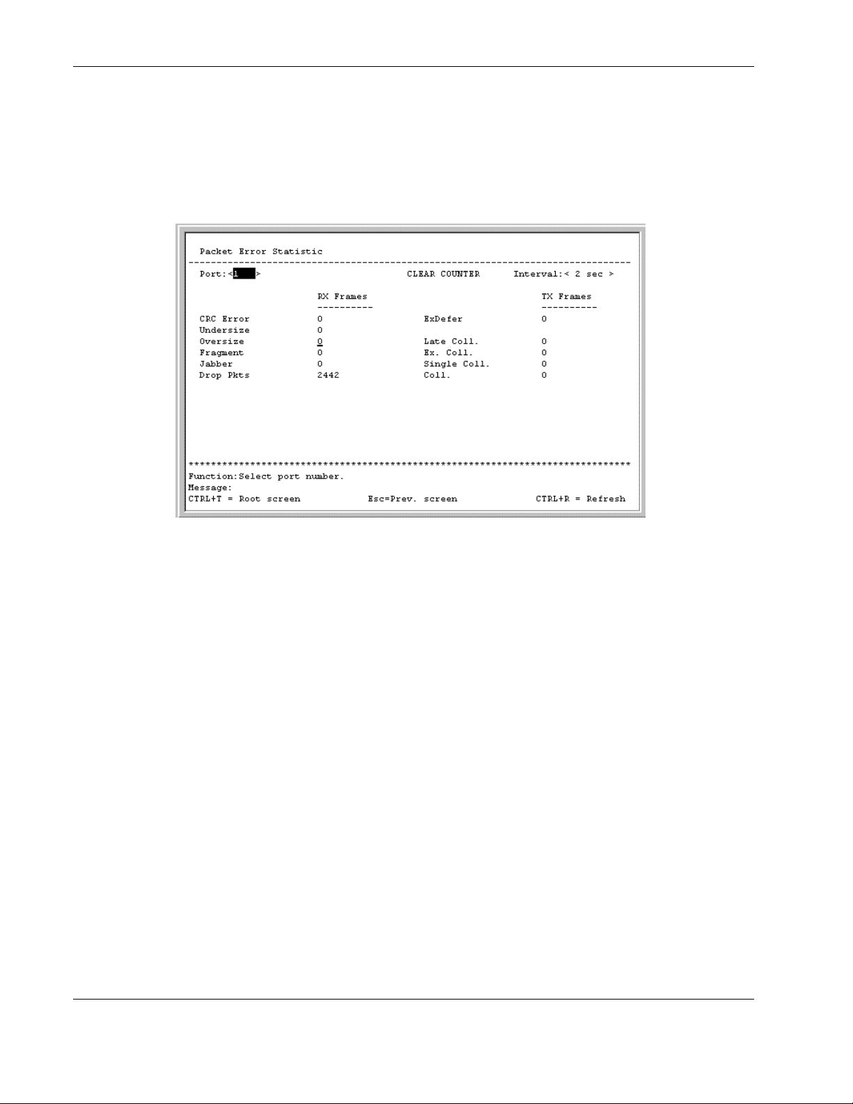
Configuring the Switch Modules using the Menu-driven Interface
Monitoring Port Error Packets
To view the error statistics for a port:
1. Highlight Port Error Packets on the Network Monitoring Menu.
2. Press the Enter key. The following screen is displayed.
The Packet Error Statistic screen displays the following for received frames:
— CRC Error—Counts Cyclic Redundancy Check (CRC) errors.
— Undersize—Displays the number of frames detected that are less than the minimum
permitted frame size of 64 bytes and have a good CRC. Undersized frames usually
indicate collision fragments, a normal network occurrence.
— Oversize—Counts packets received that were longer than 1518 octets, or if a VLAN
frame, 1522 octets, and less than the MAX_PKT_LEN. Internally, MAX_PKT_LEN
is equal to 1522.
— Fragment—Displays the number of packets less than 64 bytes with either bad
framing or an invalid CRC. These packets are normally the result of collisions.
— Jabber—Displays the number of frames with lengths more than the
MAX_PKT_LEN bytes. Internally, MAX_PKT_LEN is equal to 1522.
— Drop Pkts—Displays the number of frames that were dropped by this port since the
last switch module reboot.
The Packet Error Statistic screen displays the following for transmitted frames:
— ExDefer—Counts the number of frames for which the first transmission attempt on a
particular interface was delayed because the medium was busy.
— Late Coll.—Counts the number of times that a collision is detected later than 512 bit-
times into the transmission of a packet.
2-50 HP ProLiant BL e-Class C-GbE Interconnect Switch Menu-driven Interface Reference Guide
HP CONFIDENTIAL Codename: DeLorean Part Number: 322858-001 Last Saved On: 2/4/03 11:56 AM
Page 61
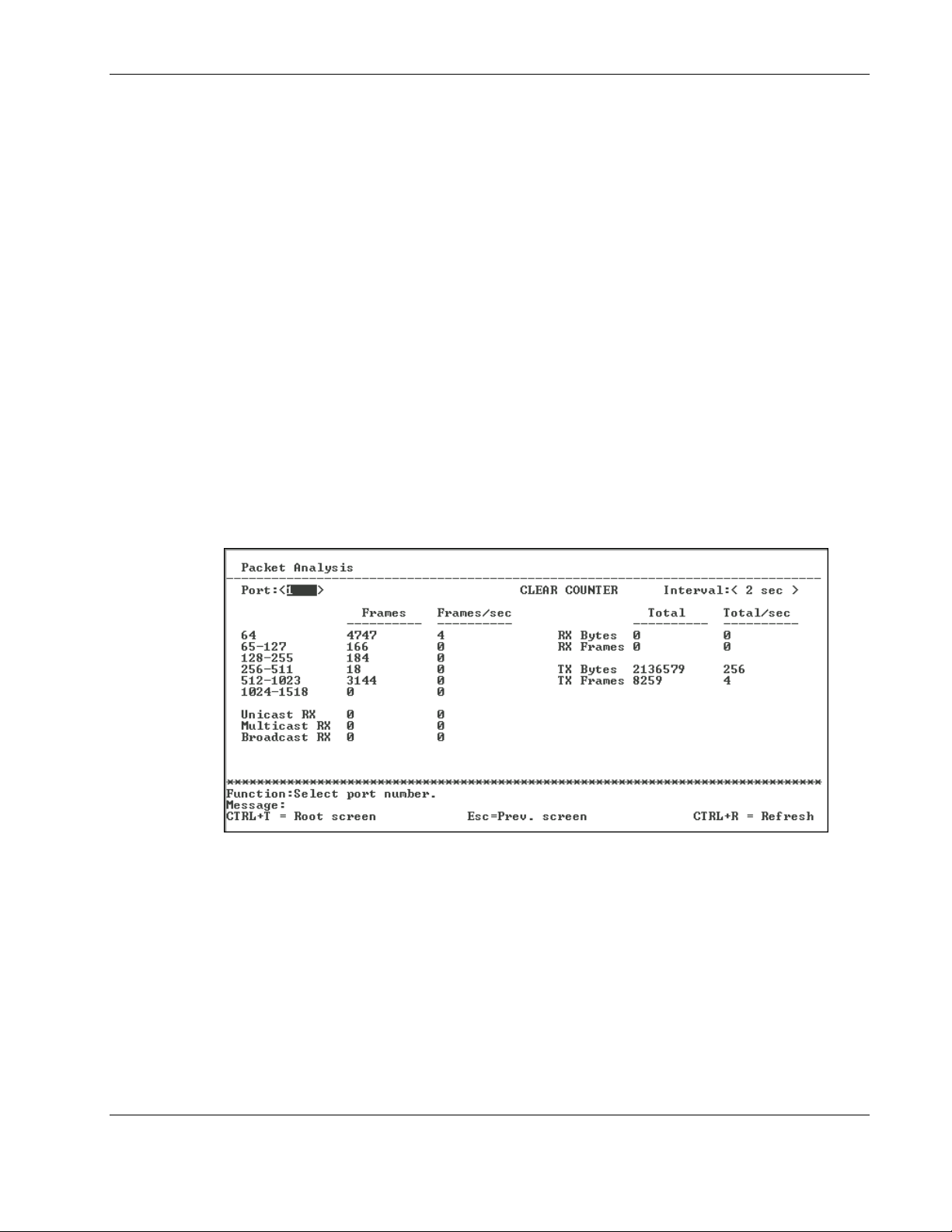
— Ex. Coll.—Counts the number of frames that experienced 16 collisions during
transmission and were aborted.
— Single Coll.—Counts the number frames that experienced exactly one collision
during transmission.
— Coll.—Counts the number of collisions that occurred during the transmission of a
frame.
3. Toggle the Port field to the number of the port to be viewed.
4. Toggle the Interval field from 2 seconds to 1 minute, or select Suspend to set the
interval at which the error statistics are updated.
5. Highlight CLEAR COUNTER.
6. Press the Enter key to reset the counters.
Monitoring Port Packet Analysis
To view an analysis of the size of packets received or transmitted by a port:
1. Highlight Port Packet Analysis on the Network Monitoring Menu.
Configuring the Switch Modules using the Menu-driven Interface
2. Press the Enter key. The following screen is displayed.
The Packet Analysis screen displays the size of packets received or transmitted by the
selected port and statistics on the number of unicast, multicast, and broadcast packets
received.
3. Toggle the Port field to the number of the port to be viewed.
HP ProLiant BL e-Class C-GbE Interconnect Switch Menu-driven Interface Reference Guide 2-51
HP CONFIDENTIAL Codename: DeLorean Part Number: 322858-001 Last Saved On: 2/4/03 11:56 AM
Page 62
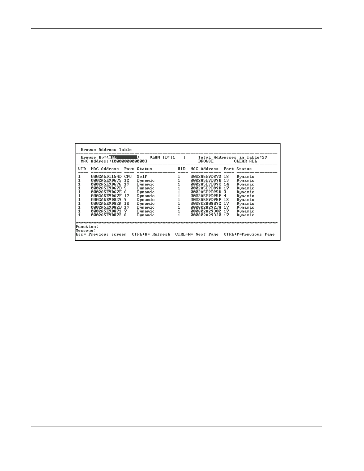
Configuring the Switch Modules using the Menu-driven Interface
4. In the Interval field, toggle to select the frequency at which the information on the screen
is refreshed. The default is two seconds.
5. To reset the counters, highlight CLEAR COUNTER.
6. Press the Enter key.
Monitoring MAC Address Forwarding Table
To view the MAC address forwarding table:
1. Highlight Browse MAC Address on the Network Monitoring Menu.
2. Press the Enter key. The following screen is displayed.
3. Toggle the Browse By field between ALL, MAC Address, Port, and VLAN. This
option sets a filter to determine which MAC addresses from the forwarding table are
displayed. ALL specifies no filter.
To search for a particular MAC address:
1. Toggle the Browse By field to MAC Address. A MAC Address field is displayed.
2. Type the MAC address in the MAC Address field, then press the Enter key.
3. Highlight BROWSE.
4. Press the Enter key to initiate the browsing action.
5. Highlight CLEAR ALL.
6. Press the Enter key to reset the table counters.
2-52 HP ProLiant BL e-Class C-GbE Interconnect Switch Menu-driven Interface Reference Guide
HP CONFIDENTIAL Codename: DeLorean Part Number: 322858-001 Last Saved On: 2/4/03 11:56 AM
Page 63
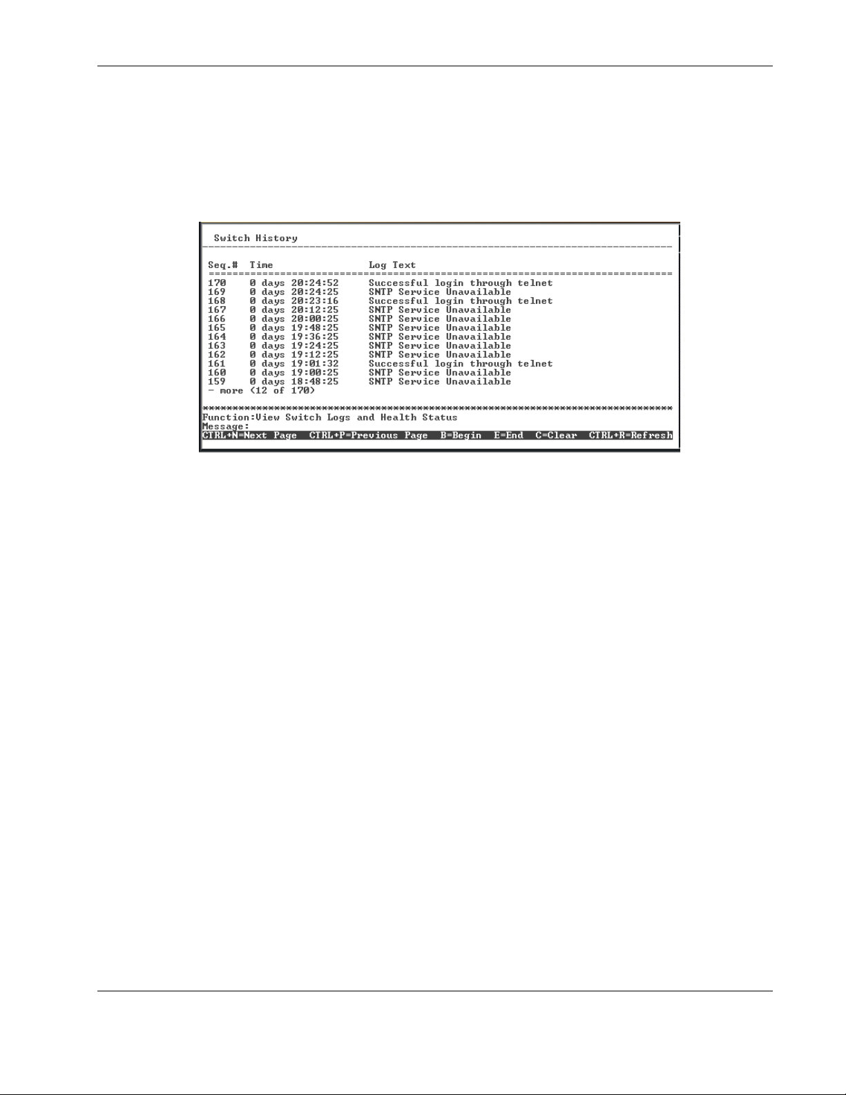
Monitoring Switch Module History
To view the Switch Module History log:
1. Highlight Switch History from the Network Monitoring Menu.
2. Press the Enter key. The following screen is displayed.
Configuring the Switch Modules using the Menu-driven Interface
The Switch History screen displays the switch module logs and health status.
To scroll through the log
•
Press the Ctrl+N keys to scroll to the next page.
•
Press the Ctrl+P keys to scroll to the previous page.
•
Press the B key to display the beginning page.
•
Press the E key to display the last page.
HP ProLiant BL e-Class C-GbE Interconnect Switch Menu-driven Interface Reference Guide 2-53
HP CONFIDENTIAL Codename: DeLorean Part Number: 322858-001 Last Saved On: 2/4/03 11:56 AM
Page 64
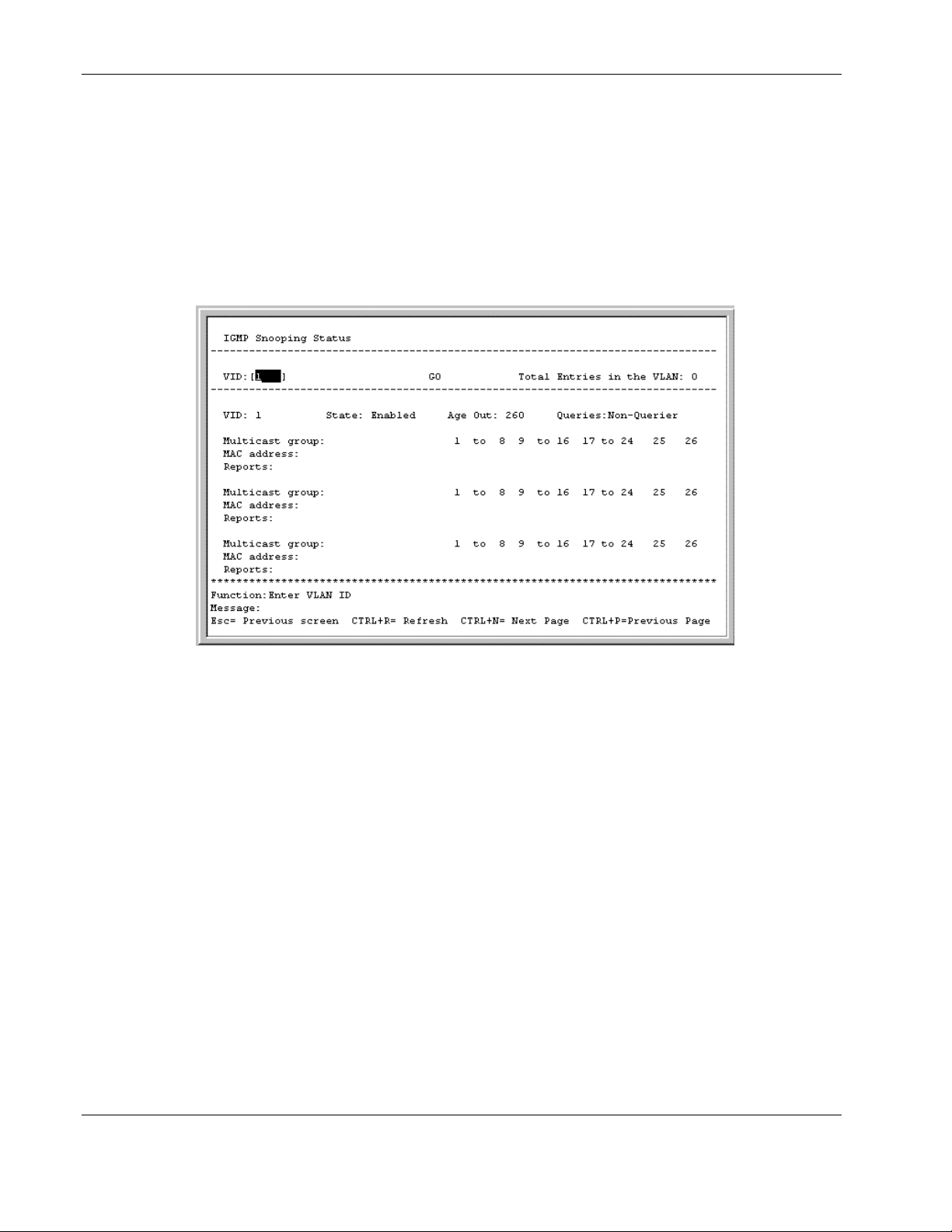
Configuring the Switch Modules using the Menu-driven Interface
Monitoring IGMP Snooping
IGMP Snooping allows the switch module to read the Multicast Group IP address and the
corresponding MAC address from IGMP packets that pass through the switch module.
To view the IGMP Snooping table:
1. Highlight IGMP Snooping on the Network Monitoring Menu.
2. Press the Enter key. The following screen is displayed.
3. Type the VLAN name in the VID field.
4. Highlight GO and press the Enter key to view the IGMP Snooping table for the selected
VLAN. The ports where the IGMP packets were snooped are displayed and designated
with an “M.” The number of IGMP reports that were snooped is also displayed in the
Reports field.
2-54 HP ProLiant BL e-Class C-GbE Interconnect Switch Menu-driven Interface Reference Guide
HP CONFIDENTIAL Codename: DeLorean Part Number: 322858-001 Last Saved On: 2/4/03 11:56 AM
Page 65
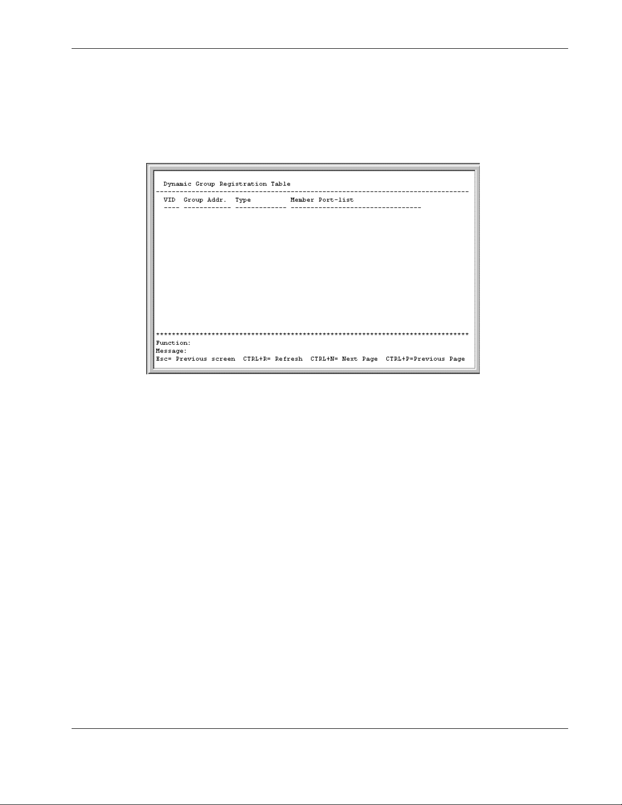
Configuring the Switch Modules using the Menu-driven Interface
Monitoring the Dynamic Group Registration Table
To view the Dynamic Group Registration Table:
1. Highlight Dynamic Group Registration Table on the Network Monitoring Menu.
2. Press the Enter key. The following screen is displayed.
The Dynamic Group Registration Table displays filtering information for VLANs
configured into the bridge by local or network management, or learned dynamically. It
specifies the set of ports to which frames received on a VLAN for this forwarding database
(FDB), and containing a specific group destination address, are allowed to be forwarded.
HP ProLiant BL e-Class C-GbE Interconnect Switch Menu-driven Interface Reference Guide 2-55
HP CONFIDENTIAL Codename: DeLorean Part Number: 322858-001 Last Saved On: 2/4/03 11:56 AM
Page 66
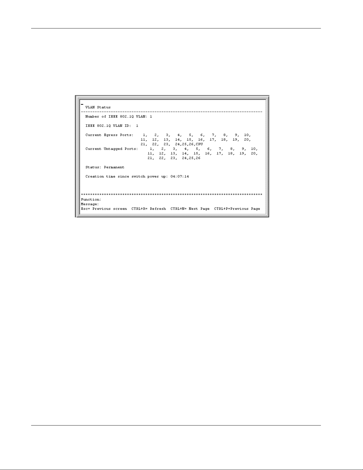
Configuring the Switch Modules using the Menu-driven Interface
Monitoring VLAN Status
To view the VLAN Status table:
1. Highlight VLAN Status on the Network Monitoring Menu.
2. Press the Enter key. The following screen is displayed.
The VLAN Status window displays which VLAN ports are egress and which ports are
untagged.
Configuring SNMP Manager
Simple Network Management Protocol (SNMP) is an Open Systems Interconnection (OSI)
Layer 7 (the application layer) protocol for remotely monitoring and configuring network
devices. SNMP enables network management stations to read and modify the settings of
gateways, routers, switches, and other network devices. SNMP can be used to perform many
of the same functions as a directly connected console, or can be used within an integrated
network management software package such as Insight Manager 7.
SNMP performs the following functions:
•
Sends and receives SNMP packets through the IP protocol
•
Collects information about the status and current configuration of network devices
•
Modifies the configuration of network devices
The switch module has software, called an agent, that processes SNMP requests. The user
program that makes the requests and collects the responses runs on the management station (a
designated computer on the network). The SNMP agent and the user program both use the
UDP/IP protocol to exchange packets.
2-56 HP ProLiant BL e-Class C-GbE Interconnect Switch Menu-driven Interface Reference Guide
HP CONFIDENTIAL Codename: DeLorean Part Number: 322858-001 Last Saved On: 2/4/03 11:56 AM
Page 67
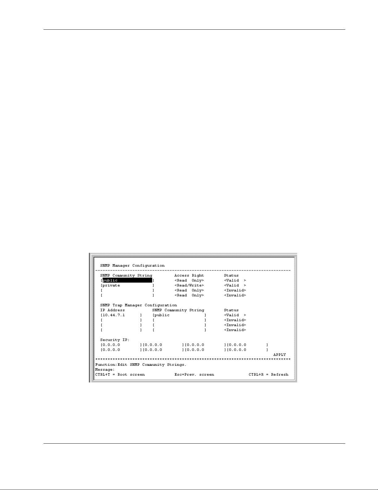
Configuring the Switch Modules using the Menu-driven Interface
The authentication protocol ensures that both the switch SNMP agent and the remote user
SNMP application program discard packets from unauthorized users. SNMP (version 1)
implements a form of security by requiring that each request include a “community string.” A
community string is an arbitrary string of characters used as a “password” to control access to
the switch module.
Traps are messages that alert you of events that occur on the switch module. The events can
be as serious as a reboot (someone accidentally reset the interconnect switch), or less serious
like a configuration file update. The switch module generates traps and sends them to the
network manager (trap recipient).
Trap recipients are special users of the network who are given certain rights and access in
overseeing the maintenance of the network. Trap recipients will receive traps sent from the
switch module, and they may take certain actions to avoid future failure or breakdown of the
network.
You can specify which network managers, may receive traps from the interconnect switch by
entering a list of the IP addresses of authorized network managers. Up to four trap-recipient
IP addresses and four corresponding SNMP community strings can be entered.
If the receiver of a request or trap does not recognize the community string, the request or
trap is ignored.
To set the SNMP Manager Configuration settings:
1. Highlight SNMP Manager Configuration on the main menu.
2. Press the Enter key. The following screen is displayed.
HP ProLiant BL e-Class C-GbE Interconnect Switch Menu-driven Interface Reference Guide 2-57
HP CONFIDENTIAL Codename: DeLorean Part Number: 322858-001 Last Saved On: 2/4/03 11:56 AM
Page 68

Configuring the Switch Modules using the Menu-driven Interface
The following parameters can be set:
— SNMP Community String—Displays the community string that is included on
SNMP request and traps sent to and from the switch module. If the receiver of a
request or trap does not recognize the community string, the request or trap is
ignored. SNMP allows up to four community strings to be defined. The community
strings “public” and “private” are defined by default. You can change the strings in
addition to adding others. You must coordinate these strings with the community
string settings you use in your network management system.
— Access Right—Allows each community string received by the switch module to be
separately set to either Read Only, meaning that the community member can only
view switch settings, or Read/Write, which allows the member to change settings in
the switch module.
— Status—Determines whether this community string entry is Valid or Invalid. An
entry can be disabled by changing its status to Invalid.
— IP Address—Displays the IP address of the network management station designated
to receive traps.
— Security IP—Allows you to create a list of IP addresses that are allowed to access
the switch module by means of SNMP, Telnet, or the Web.
3. After making your changes, highlight APPLY.
4. Press the Enter key.
IMPORTANT: To save the configuration settings permanently, you must enter them into NVRAM
using the Save Changes option on the main menu. Refer to the “Saving Changes” section earlier
in this chapter.
Using System Utilities
Trivial File Transfer Protocol (TFTP) services allow the switch firmware to be upgraded by
transferring a new firmware file from a TFTP server to the switch module. A configuration
file can also be loaded into the switch module from a TFTP server, switch module settings
can be saved to the TFTP server, and a history log can be uploaded from the switch module to
the TFTP server.
To set the system utilities settings:
1. Highlight System Utilities on the main menu.
2-58 HP ProLiant BL e-Class C-GbE Interconnect Switch Menu-driven Interface Reference Guide
HP CONFIDENTIAL Codename: DeLorean Part Number: 322858-001 Last Saved On: 2/4/03 11:56 AM
Page 69
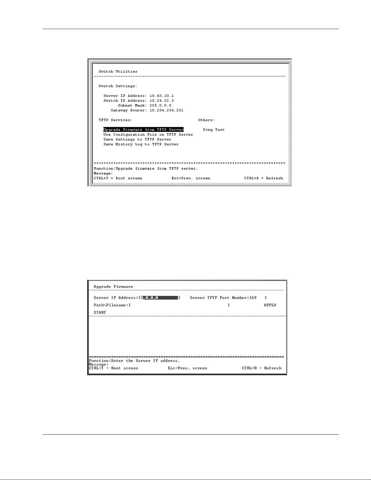
Configuring the Switch Modules using the Menu-driven Interface
2. Press the Enter key. The following screen is displayed.
The Switch Utilities menu displays the server IP address and the switch module IP address,
subnet mask, and gateway router addresses. The bottom of the screen provides a menu for
using TFTP services and a performing a ping test.
Upgrading Firmware from a TFTP Server
To upgrade the firmware from a TFTP server:
1. Highlight Upgrade Firmware from TFTP Server on the Switch Utilities menu.
2. Press the Enter key. The following screen is displayed.
3. Type the IP address of the TFTP server in the Server IP Address field.
IMPORTANT: The TFTP server must be on the same IP subnet as the switch module.
4. Type the port number of the TFTP server you wish to connect to in the Server TFTP
Port Number field.
HP ProLiant BL e-Class C-GbE Interconnect Switch Menu-driven Interface Reference Guide 2-59
HP CONFIDENTIAL Codename: DeLorean Part Number: 322858-001 Last Saved On: 2/4/03 11:56 AM
Page 70

Configuring the Switch Modules using the Menu-driven Interface
5. Type the path and the filename to the firmware file on the TFTP server in the
Path\Filename field.
IMPORTANT: The TFTP server must be running TFTP server software to perform the file transfer.
TFTP server software is included in many network management software packages, or it can be
obtained as part of the interconnect switch utilities package.
6. Highlight APPLY.
7. Press the Enter key to record the IP address of the TFTP server.
8. Highlight START.
9. Press the Enter key to initiate the file transfer.
IMPORTANT: To save the configuration settings permanently, you must enter them into NVRAM
using the Save Changes option on the main menu. Refer to the “Saving Changes” section earlier
in this chapter.
IMPORTANT: A downloadable smart component, which further simplifies upgrading the switch
module firmware, is available at the following website:
www.compaq.com/support/servers
Downloading Configuration File from a TFTP Server
IMPORTANT: Configuration files used in the earlier version of the interconnect switch (firmware
version 1.0) are not supported by the present version (firmware version 2.0). The switch module
Information window displays the firmware version.
A configuration file can be downloaded from a TFTP server to the switch module. This file is
then used by the switch module to configure itself. Beginning in firmware version 2.0.0,
switch firmware configuration files are specified in XML format.
Downloaded XML configuration files do not need to specify every possible parameter. Only
the configuration parameters specified will be modified; others will remain unchanged.
To download a switch module configuration file from a TFTP server:
1. Highlight Use a Configuration File on TFTP Server on the Switch Utilities menu.
2-60 HP ProLiant BL e-Class C-GbE Interconnect Switch Menu-driven Interface Reference Guide
HP CONFIDENTIAL Codename: DeLorean Part Number: 322858-001 Last Saved On: 2/4/03 11:56 AM
Page 71
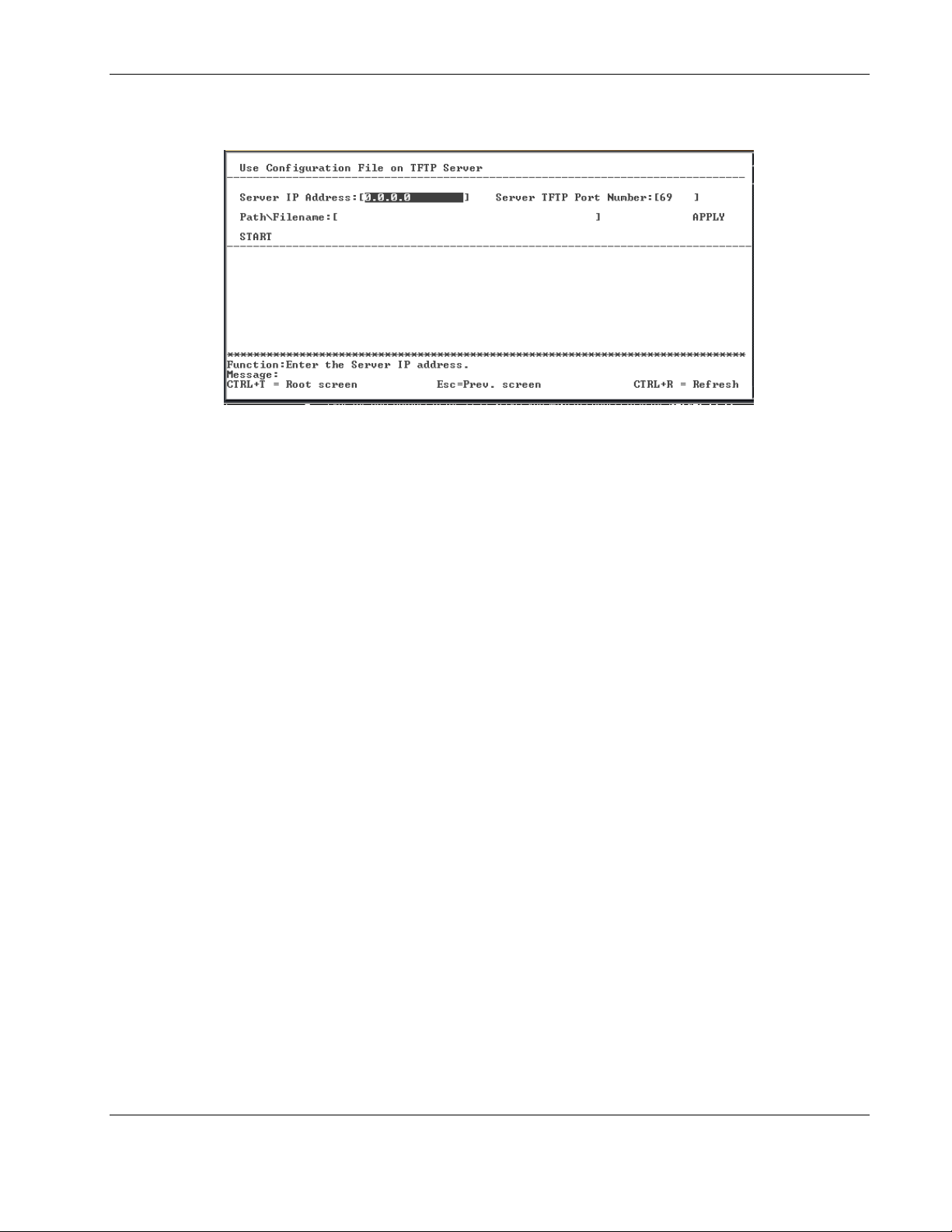
Configuring the Switch Modules using the Menu-driven Interface
2. Press the Enter key. The following screen is displayed.
3. Type the IP address of the TFTP server in the Server IP Address field.
4. Type the port number of the TFTP server you wish to connect to in the Server TFTP
Port Number field.
5. Type the location of the switch module configuration file on the TFTP server in the
Path\Filename field.
6. Highlight APPLY.
7. Press the Enter key to record the IP address and location of the TFTP server.
8. Highlight START.
9. Press the Enter key to initiate the file transfer.
IMPORTANT: To save the configuration settings permanently, you must enter them into NVRAM
using the Save Changes option on the main menu. Refer to the “Saving Changes” section earlier
in this chapter.
NOTE: For additional information, refer to Appendix H, XML Configuration, in the HP ProLiant
e-class C-GbE Interconnect Switch User Guide.
HP ProLiant BL e-Class C-GbE Interconnect Switch Menu-driven Interface Reference Guide 2-61
HP CONFIDENTIAL Codename: DeLorean Part Number: 322858-001 Last Saved On: 2/4/03 11:56 AM
Page 72
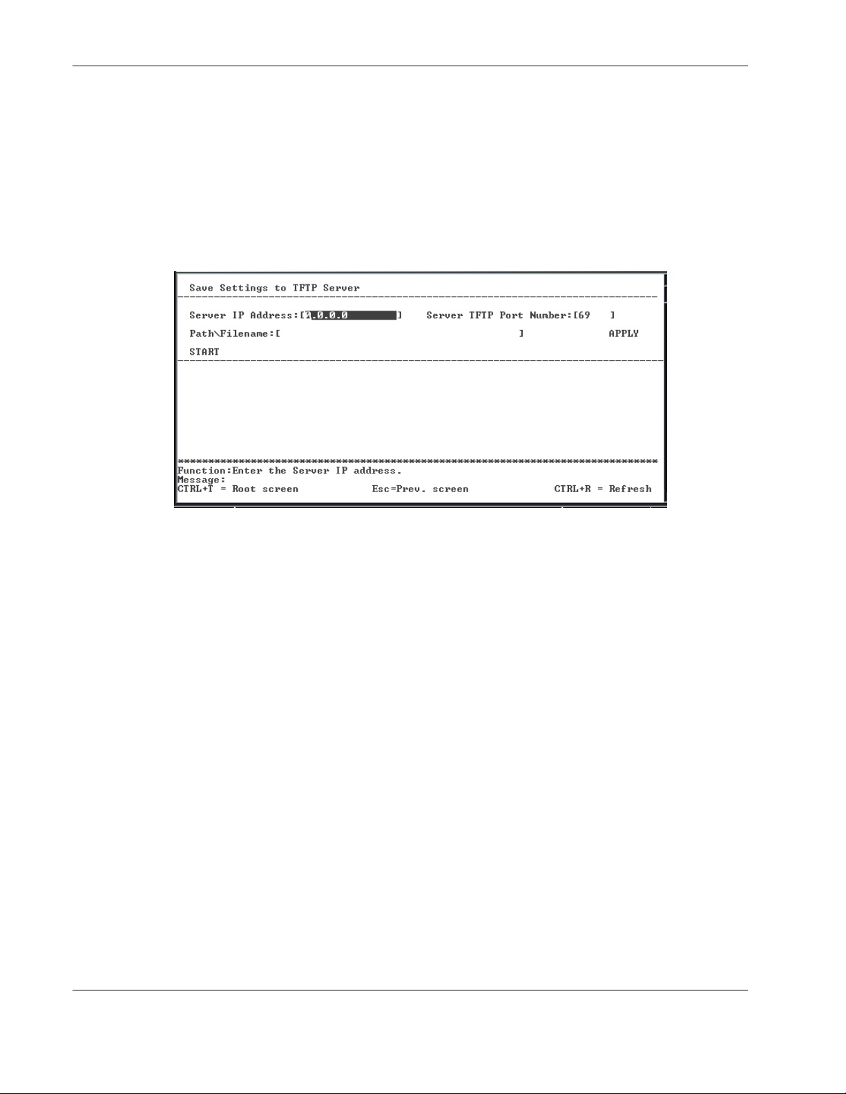
Configuring the Switch Modules using the Menu-driven Interface
Saving Settings to a TFTP Server
After completing the final configuration for the switch module, HP highly recommends that
you save the switch module configuration file to TFTP server storage.
To save the switch module configuration file to a TFTP server:
1. Highlight Save Settings to TFTP Server on the Switch Utilities menu.
2. Press the Enter key. The following screen is displayed.
3. Type the IP address of the TFTP server in the Server IP Address field.
4. Type the port number of the TFTP server you wish to connect to in the Server TFTP
Port Number field.
5. Type the location of the switch module configuration file on the TFTP server in the
Path\Filename field.
6. Highlight APPLY.
7. Press the Enter key.
8. Highlight START.
9. Press the Enter key to initiate the file transfer.
IMPORTANT: To save the configuration settings permanently, you must enter them into NVRAM
using the Save Changes option on the main menu. Refer to the “Saving Changes” section earlier
in this chapter.
2-62 HP ProLiant BL e-Class C-GbE Interconnect Switch Menu-driven Interface Reference Guide
HP CONFIDENTIAL Codename: DeLorean Part Number: 322858-001 Last Saved On: 2/4/03 11:56 AM
Page 73
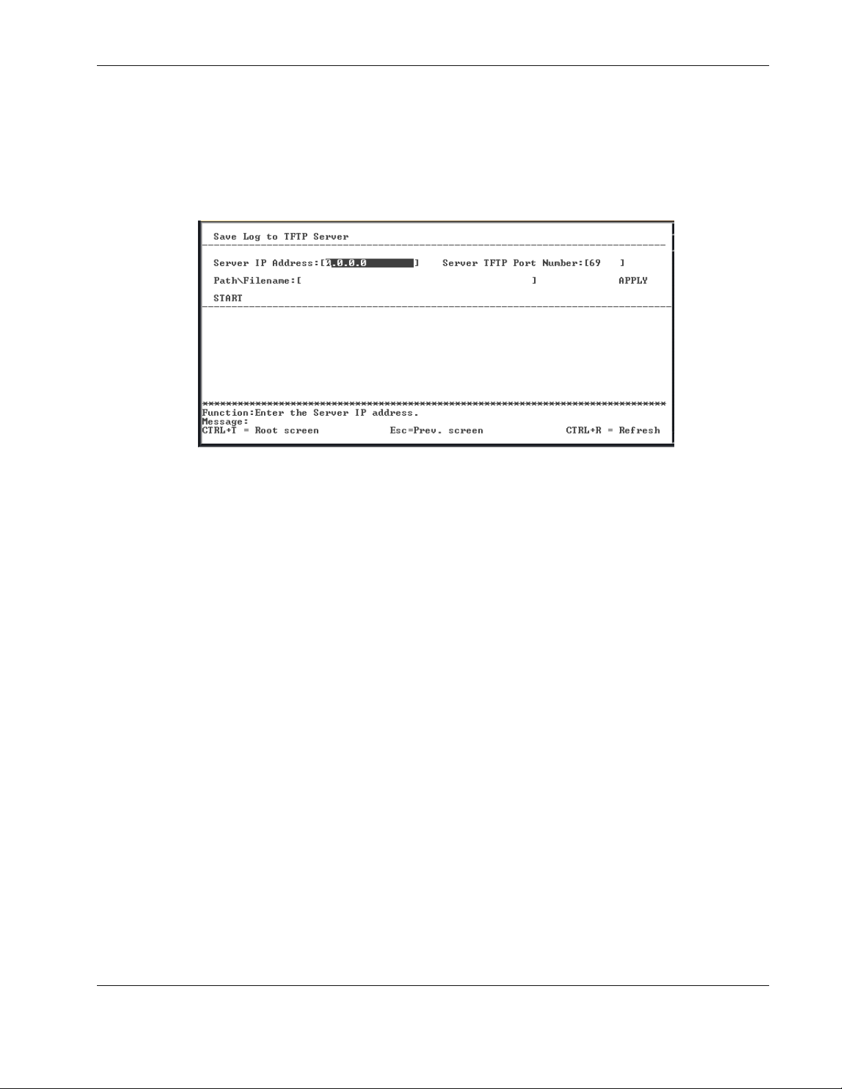
Configuring the Switch Modules using the Menu-driven Interface
Saving the History Log to a TFTP Server
To save the History Log on a TFTP server:
1. Highlight Save History Log to TFTP Server on the Switch Utilities menu.
2. Press the Enter key. The following screen is displayed.
3. Type the IP address of the TFTP server in the Server IP Address field.
4. Type the port number of the TFTP server you wish to connect in the Server TFTP Port
Number field.
5. Type the path and filename for the history log on the TFTP server in the Path\Filename
field.
6. Highlight APPLY.
7. Press the Enter key to make the changes current.
8. Highlight START.
9. Press the Enter key to initiate the file transfer.
IMPORTANT: To save the configuration settings permanently, you must enter them into NVRAM
using the Save Changes option on the main menu. Refer to the “Saving Changes” section earlier
in this chapter.
HP ProLiant BL e-Class C-GbE Interconnect Switch Menu-driven Interface Reference Guide 2-63
HP CONFIDENTIAL Codename: DeLorean Part Number: 322858-001 Last Saved On: 2/4/03 11:56 AM
Page 74
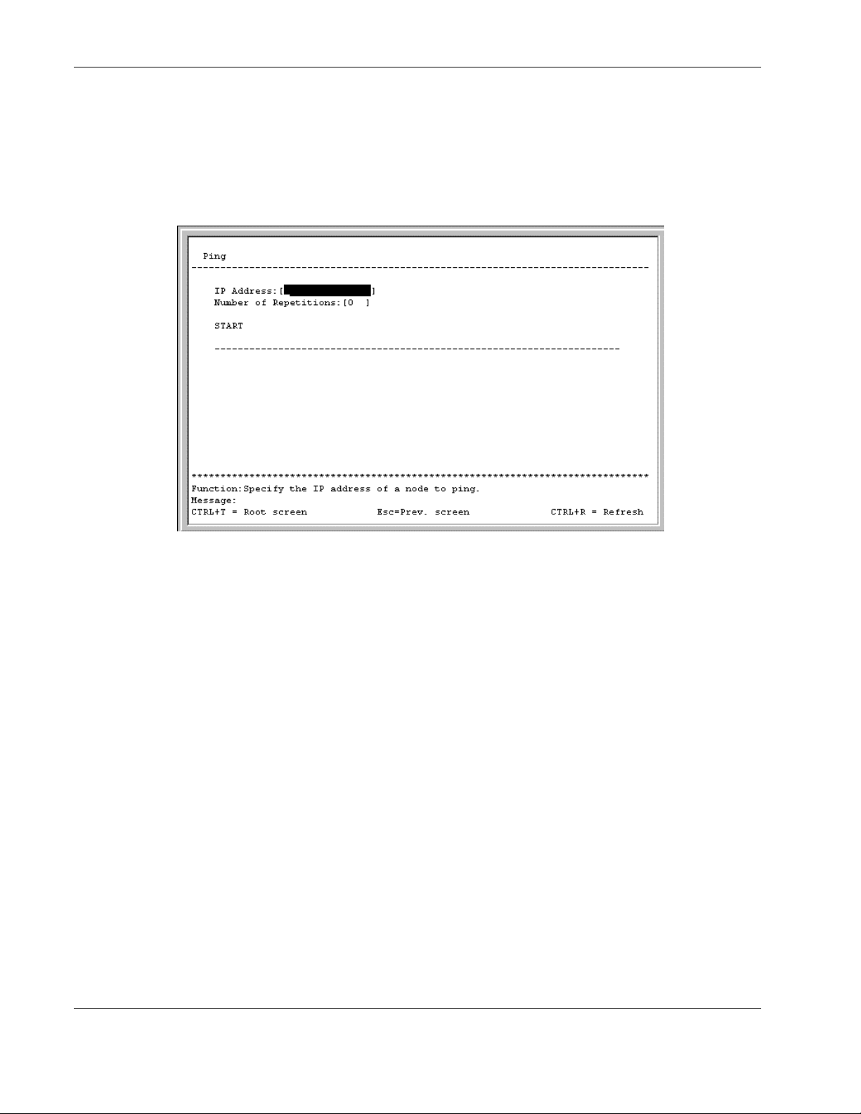
Configuring the Switch Modules using the Menu-driven Interface
Performing a Ping Test
To test the connection with another network device using Ping:
1. Highlight Ping Test on the Switch Utilities menu.
2. Press the Enter key. The following screen is displayed.
3. Type the IP address of the network device to be pinged in the IP Address field.
4. Type the number of test packets to be sent (three is usually enough) in the Number of
Repetitions field.
5. Highlight START.
6. Press the Enter key.
IMPORTANT: To save the configuration settings permanently, you must enter them into NVRAM
using the Save Changes option on the main menu. Refer to the “Saving Changes” section earlier
in this chapter.
2-64 HP ProLiant BL e-Class C-GbE Interconnect Switch Menu-driven Interface Reference Guide
HP CONFIDENTIAL Codename: DeLorean Part Number: 322858-001 Last Saved On: 2/4/03 11:56 AM
Page 75
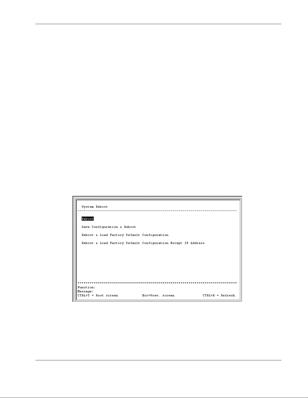
Rebooting the Switch Module
The switch module reboot options are:
•
Reboot—Restarts the switch module. Any configuration settings not saved using Save
Changes from the main menu are lost. The switch module configuration is restored to the
last configuration saved in NVRAM.
•
Save Configuration & Reboot—Saves the configuration to NVRAM (identical to using
Save Changes) and then restarts the switch module.
•
Reboot & Load Factory Default Configuration—Restarts the switch module using the
default factory configuration. All user-defined configuration data is lost.
•
Reboot & Load Factory Default Configuration Except IP Address—Restarts the
switch module using the default factory configuration, except the user-configured IP
address, which is retained. All other configuration data is lost. If you want your IP
address to default from DHCP or BOOTP, do not choose this option.
NOTE: Refer to Appendix C in the HP ProLiant e-Class C-GbE Interconnect Switch User Guide for a
list of factory default settings.
Configuring the Switch Modules using the Menu-driven Interface
To reboot the switch module from the console:
1. Highlight Reboot on the main menu.
2. Press the Enter key. The following screen is displayed.
3. Highlight the appropriate selection.
HP ProLiant BL e-Class C-GbE Interconnect Switch Menu-driven Interface Reference Guide 2-65
HP CONFIDENTIAL Codename: DeLorean Part Number: 322858-001 Last Saved On: 2/4/03 11:56 AM
Page 76
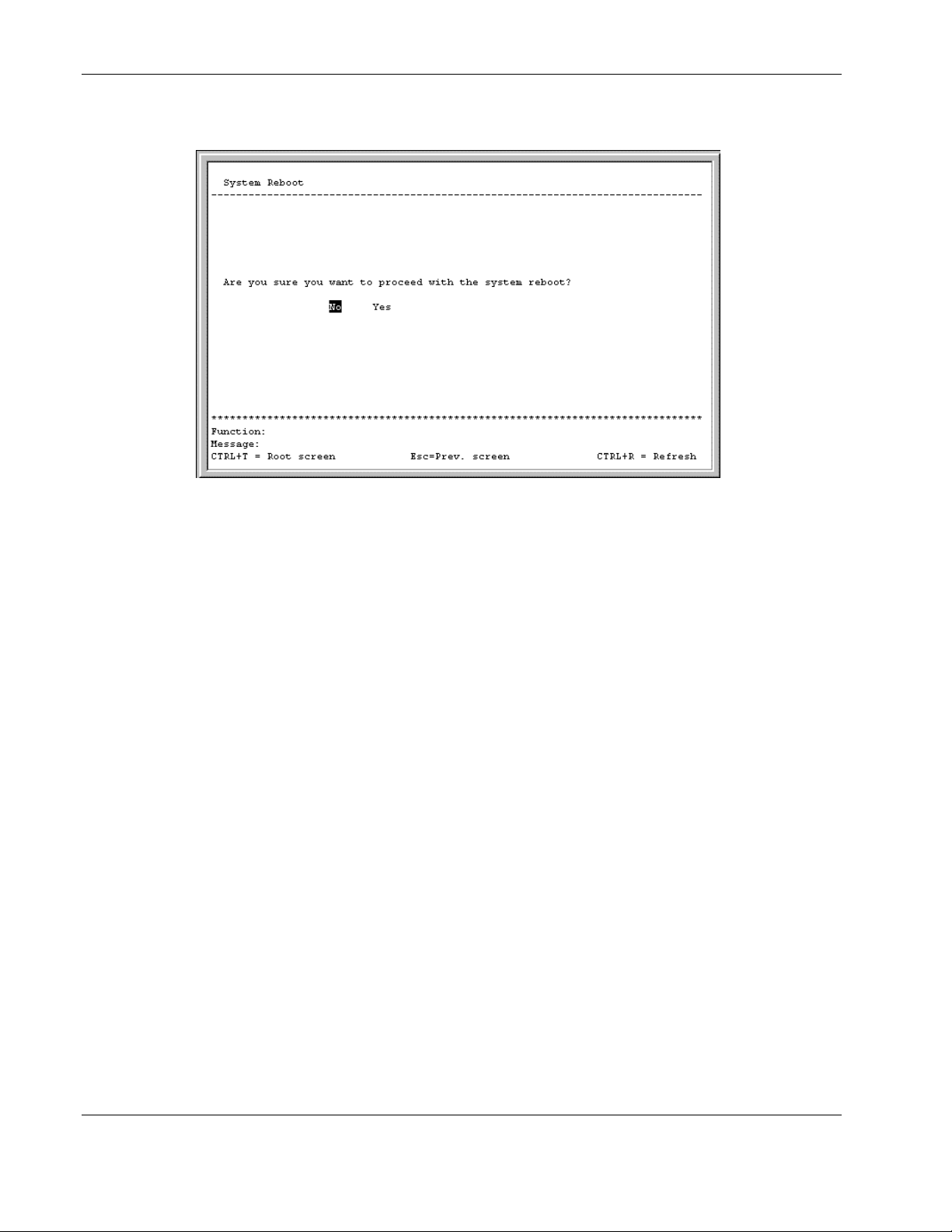
Configuring the Switch Modules using the Menu-driven Interface
4. Press the Enter key. The following screen is displayed.
5. Highlight Yes.
6. Press the Enter key.
Logging Out
To exit the setup pages, select Logout on the Main menu. The Account Login screen is
displayed.
2-66 HP ProLiant BL e-Class C-GbE Interconnect Switch Menu-driven Interface Reference Guide
HP CONFIDENTIAL Codename: DeLorean Part Number: 322858-001 Last Saved On: 2/4/03 11:56 AM
Page 77

A F
accessing switch field-level help 1-4
procedure 1-2 firmware upgrades 2-59
advanced settings 2-9
auto-logout 2-11
G
Index
B
bandwidth, configuring 2-14
basic settings 2-9
Bootstrap Protocol (BOOTP)
IP address assignment 2-7, 2-8
broadcast storm
configuring threshold 2-38
C
Class of Service (CoS) 2-39
Class of Service (CoS) packet prioritization 2-40
class of traffic 2-42
community names, SNMP 2-57
component-level repairs v
configuration 1-1, 2-1
current egress bandwidth settings 2-18
current ingress bandwidth settings 2-16
D
date, configuring 2-45
DA-unknown storm, configuring threshold 2-38
default gateway 2-9
default settings
port priority 2-41
deleting user accounts 2-6
Destination-Address Filtering Table 2-23
DHCP (Dynamic Host Configuration Protocol)
IP address assignment 2-7, 2-8
Dynamic Group Registration Table 2-55
E
egress bandwidth settings 2-17
error packets, monitoring
grounding v
grounding plug v
group address filter mode 2-12
GVRP (GARP VLAN Registration Protocol)
settings 2-12, 2-32
H
help resources vi
history, switch
saving with TFTP server 2-63
history, switch 2-53
HP authorized reseller vi
I
IGMP (Internet Group Management Protocol)
snooping 2-12
monitoring 2-54
overview 2-33
ingress bandwidth settings 2-15
ingress filtering 2-30
ingress filtering of ports 2-31
Integrated Administrator (iA) connectors
accessing switch modules through 1-2
IP addresses 2-6
L
login procedures
initial setup 1-2
M
MAC address aging time 2-11, 2-12
MAC addresses
configuring 2-44
HP ProLiant BL e-Class C-GbE Interconnect Switch Menu-driven Interface Reference Guide Index-1
HP CONFIDENTIAL Codename: DeLorean Part Number: 322858-001 Last Saved On: 2/4/03 11:57 AM
Page 78

Index
monitoring 2-52
manual assignment of IP addresses 2-7, 2-8
mirroring of ports 2-37
monitoring switch functions 2-47
multicast filtering 2-33
multicast filtering, configuring 2-25
multicast storm, configuring 2-38
N
Network Monitoring Menu 2-47
NVRAM (non-volatile RAM) 2-1
P
packets, data
error monitoring 2-50
monitoring 2-51
prioritization service 2-39, 2-40
ping test 2-64
port trunking 2-35
ports
assigning VLANs to 2-29
configuring settings 2-13
default priority 2-41
GVRP settings 2-32
ingress filtering for 2-31
mirroring of 2-37
monitoring utilization 2-48
security for 2-43
priority MAC addresses 2-44
priority, port, configuring 2-41
privileges, user 2-3
protocols, network
BOOTP 2-7, 2-8
DHCP 2-7, 2-8
GVRP 2-12, 2-32
SNMP 2-56
SNTP 2-13, 2-45
PVID (port VLAN ID) 2-29
R
rebooting switch 2-65
remote management IP interface settings 2-6
restart egress bandwidth settings 2-17
restart ingress bandwidth settings 2-15
S
scheduling mechanism for CoS queues 2-12
security
configuring port 2-43
SNMP (Simple Network Management
Protocol) 2-56
SNTP (Simple Network Time Protocol) 2-13, 2-45
spanning tree protocol (STP)
configuring 2-20
spanning tree protocol (STP) 2-19
static (Destination-Address Filtering) table 2-23
static VLAN entry 2-28
subnet mask 2-8
Switch Information menu 2-9
system messages 1-4
system utilities 2-58
T
technician notes v
telephone numbers vi
Telnet 2-12
TFTP (Trivial File Transfer Protocol) server
updating switch from 2-59
time, configuring 2-45
traffic classes, configuring 2-42
trunk load sharing algorithm 2-12
trunking feature
monitoring utilization 2-49
trunking feature 2-35
U
unicast filtering, configuring 2-24
updating user accounts 2-5
upgrading firmware 2-59
users
privilege levels 2-3
V
ventilation clearances v
VLANs (virtual local area networks)
monitoring 2-56
VLANs (virtual local area networks) 2-26
W
warranty vi
Web 2-12
saving changes 2-1
Index-2 HP ProLiant BL e-Class C-GbE Interconnect Switch Menu-driven Interface Reference Guide
HP CONFIDENTIAL Codename: DeLorean Part Number: 322858-001 Last Saved On: 2/4/03 11:57 AM
 Loading...