

HP ProLiant C-GbE, ProLiant BL e-Class C-CbE Reference Manual

HP ProLiant BL e-Class C-GbE Interconnect
Switch Menu-driven Interface
Reference Guide
February 2003 (First Edition)
Part Number 322858-001
HP CONFIDENTIAL Codename: DeLorean Part Number: 322858-001 Last Saved On: 2/4/03 11:52 AM

© 2003 Hewlett-Packard Development Company, L.P.
Microsoft®, Windows®, and Windows NT® are U.S. registered trademarks of Microsoft Corporation.
Hewlett-Packard Company shall not be liable for technical or editorial errors or omissions contained herein. The
information in this document is provided “as is” without warranty of any kind and is subject to change without
notice. The warranties for HP products are set forth in the express limited warranty statements accompanying such
products. Nothing herein should be construed as constituting an additional warranty.
Confidential computer software. Valid license from HP required for possession, use or copying. Consistent with
FAR 12.211 and 12.212, Commercial Computer Software, Computer Software Documentation, and Technical
Data for Commercial Items are licensed to the U.S. Government under vendor's standard commercial license.
HP ProLiant BL e-Class C-GbE Interconnect Switch Menu-driven Interface Reference Guide
February 2003 (First Edition)
Part Number 322858-001
HP CONFIDENTIAL Codename: DeLorean Part Number: 322858-001 Last Saved On: 2/4/03 11:52 AM

Contents
About This Guide
Technician Notes...........................................................................................................................................v
Where to Go for Additional Help.................................................................................................................vi
Telephone Numbers...............................................................................................................................vi
Chapter 1
Overview
Introduction ............................................................................................................................................... 1-1
Additional References ............................................................................................................................... 1-1
Accessing the Switch Modules.................................................................................................................. 1-2
Moving Between the Console Management Interfaces............................................................................. 1-3
Using the Menu-driven Interface............................................................................................................... 1-3
Navigation Features ............................................................................................................................ 1-4
Help and System Messages................................................................................................................. 1-4
Configuring the Switch Modules............................................................................................................... 1-4
Chapter 2
Configuring the Switch Modules using the Menu-driven Interface
Overview ................................................................................................................................................... 2-1
Saving Changes ......................................................................................................................................... 2-1
Managing User Accounts .......................................................................................................................... 2-3
Adding a User Account....................................................................................................................... 2-3
Updating User Account Information .................................................................................................. 2-5
Displaying User Account Information................................................................................................ 2-6
Deleting a User Account..................................................................................................................... 2-6
Configuring the Remote Management IP Interface Settings..................................................................... 2-6
Setting the Remote Management IP Interface Settings ...................................................................... 2-7
Displaying Basic Interconnect Switch Information................................................................................... 2-9
Configuring Advanced Switch Module Features .................................................................................... 2-11
Configuring Port Settings........................................................................................................................ 2-13
Configuring Bandwidth........................................................................................................................... 2-14
Configuring Restart Port Ingress Bandwidth .................................................................................... 2-15
Displaying Current Port Ingress Bandwidth ..................................................................................... 2-16
Configuring Restart Port Egress Bandwidth..................................................................................... 2-17
Displaying Current Port Egress Bandwidth Settings ........................................................................ 2-18
Configuring Spanning Tree Protocol....................................................................................................... 2-19
Setting Spanning Tree Parameters on the Switch Module Level...................................................... 2-20
Setting Spanning Tree Parameters at the Port Level......................................................................... 2-21
HP ProLiant BL e-Class C-GbE Interconnect Switch Menu-driven Interface Reference Guide iii
HP CONFIDENTIAL Codename: DeLorean Part Number: 322858-001 Last Saved On: 2/4/03 11:52 AM

Contents
Configuring Static (Destination Address) Filtering Table ....................................................................... 2-22
Configuring VLANs ................................................................................................................................2-26
Default VLAN...................................................................................................................................2-26
Creating an 802.1 Static VLAN ........................................................................................................2-28
Setting the PVID for a Port for a Specific VLAN.............................................................................2-29
Enabling Ingress Filtering on a Per Port Basis..................................................................................2-30
Configuring GVRP ..................................................................................................................................2-32
Configuring IGMP Snooping...................................................................................................................2-33
Configuring Port Trunking ......................................................................................................................2-35
Considerations when Creating a Port Trunking Group .....................................................................2-35
Configuring Port Mirroring......................................................................................................................2-37
Configuring Thresholds for Broadcast, Multicast, Unknown Storm Prevention or Monitoring .............2-38
Configuring Class of Service, Default Port Priority, and Traffic Class...................................................2-39
Setting Class of Service..................................................................................................................... 2-40
Setting Port Priority........................................................................................................................... 2-41
Setting Traffic Class.......................................................................................................................... 2-42
Configuring Port Security ........................................................................................................................2-43
Configuring Priority MAC Addresses .....................................................................................................2-44
Configuring the Switch Module Date and Time...................................................................................... 2-45
Monitoring Switch Module Functions .....................................................................................................2-47
Monitoring Port Utilization ...............................................................................................................2-48
Monitoring Trunk Utilization............................................................................................................ 2-49
Monitoring Port Error Packets...........................................................................................................2-50
Monitoring Port Packet Analysis.......................................................................................................2-51
Monitoring MAC Address Forwarding Table................................................................................... 2-52
Monitoring Switch Module History .................................................................................................. 2-53
Monitoring IGMP Snooping..............................................................................................................2-54
Monitoring the Dynamic Group Registration Table..........................................................................2-55
Monitoring VLAN Status.................................................................................................................. 2-56
Configuring SNMP Manager ................................................................................................................... 2-56
Using System Utilities .............................................................................................................................2-58
Upgrading Firmware from a TFTP Server ........................................................................................2-59
Downloading Configuration File from a TFTP Server .....................................................................2-60
Saving Settings to a TFTP Server .....................................................................................................2-62
Saving the History Log to a TFTP Server .........................................................................................2-63
Performing a Ping Test......................................................................................................................2-64
Rebooting the Switch Module .................................................................................................................2-65
Logging Out............................................................................................................................................. 2-66
Index
iv HP ProLiant BL e-Class C-GbE Interconnect Switch Menu-driven Interface Reference Guide
HP CONFIDENTIAL Codename: DeLorean Part Number: 322858-001 Last Saved On: 2/4/03 11:52 AM
This guide can be used for reference when configuring the interconnect switch through the
menu-driven interface
WARNING: To reduce the risk of personal injury from electric shock and hazardous
energy levels, only authorized service technicians should attempt to repair this
equipment. Improper repairs can create conditions that are hazardous.
Technician Notes
WARNING: Only authorized technicians trained by HP should attempt to repair this
equipment. All troubleshooting and repair procedures are detailed to allow only
subassembly/module-level repair. Because of the complexity of the individual boards
and subassemblies, no one should attempt to make repairs at the component level or
to make modifications to any printed wiring board. Improper repairs can create a safety
hazard.
WARNING: To reduce the risk of personal injury from electric shock and hazardous
energy levels, do not exceed the level of repairs specified in these procedures.
Because of the complexity of the individual boards and subassemblies, do not attempt
to make repairs at the component level or to make modifications to any printed wiring
board. Improper repairs can create conditions that are hazardous.
WARNING: To reduce the risk of electric shock or damage to the equipment:
• Disconnect power from the system by unplugging all power cords from the power
supplies.
• Do not disable the power cord grounding plug. The grounding plug is an important
safety feature.
About This Guide
• Plug the power cord into a grounded (earthed) electrical outlet that is easily
accessible at all times.
CAUTION: To properly ventilate the system, you must provide at least 7.6 cm (3.0 in.) of
clearance at the front and back of the server.
CAUTION: The computer is designed to be electrically grounded (earthed). To ensure proper
operation, plug the AC power cord into a properly grounded AC outlet only.
HP ProLiant BL e-Class C-GbE Interconnect Switch Menu-driven Interface Reference Guide v
HP CONFIDENTIAL Codename: DeLorean Part Number: 322858-001 Last Saved On: 2/4/03 11:52 AM

About This Guide
NOTE: Any indications of component replacement or printed wiring board modifications may void any
warranty.
Where to Go for Additional Help
In addition to this guide, the following information sources are available:
• HP ProLiant BL e-Class C-GbE Interconnect Switch User Guide
• HP ProLiant BL e-Class C-GbE Interconnect Switch Command Line Interface Reference
Guide
• HP ProLiant BL e-Class C-GbE Interconnect Switch Web-based Interface Reference
Guide
• Service Quick Reference Guide
• Service training guides
• Service advisories and bulletins
• QuickFind information services
• Insight Manager software
Telephone Numbers
For the name of your nearest HP authorized reseller:
• In the United States, call 1-800-345-1518.
• In Canada, call 1-800-263-5868.
For HP technical support:
• In the United States and Canada, call 1-800-652-6672.
• Outside the United States and Canada, refer to
www.hp.com
vi HP ProLiant BL e-Class C-GbE Interconnect Switch Menu-driven Interface Reference Guide
HP CONFIDENTIAL Codename: DeLorean Part Number: 322858-001 Last Saved On: 2/4/03 11:52 AM

Introduction
The ProLiant BL e-Class C-GbE Interconnect Switch provides two console management
interfaces and a Web-based management interface. The command line interface (CLI) and
menu-driven interface allow you to set up and control the switch modules using either the
serial or Ethernet ports on the switch. This guide discusses how to use the menu-driven
interface to set up and manage the interconnect switch.
The menu-driven interface can be accessed either with an ordinary terminal (or terminal
emulator) or over the network using the TCP/IP Telnet protocol. You can use the
menu-driven interface to perform basic network management functions and to configure the
switch modules for management using an Simple Network Management Protocol
(SNMP)-based network management system.
Additional References
1
Overview
Additional information about installling and configuring the interconnect switch is available
in the following guides, which are located on the ProLiant BL e-Class C-GbE Interconnect
Switch Management System Utilities and User Documentation CD.
•
HP ProLiant BL e-Class C-GbE Interconnect Switch User Guide
•
HP ProLiant BL e-Class C-GbE Interconnect Switch Command Line Interface Reference
Guide
•
HP ProLiant BL e-Class C-GbE Interconnect Switch Web-based Interface Reference
Guide
HP ProLiant BL e-Class C-GbE Interconnect Switch Menu-driven Interface Reference Guide 1-1
HP CONFIDENTIAL Codename: DeLorean Part Number: 322858-001 Last Saved On: 2/4/03 11:53 AM
Overview
Accessing the Switch Modules
After the Integrated Administrator is configured, you can access and configure the switch
modules through the Integrated Administrator software. For information on how to configure
the Integrated Administrator, refer to the “Configuring the Integrated Administrator” section
in the HP ProLiant BL e-Class C-GbE Interconnect Switch User Guide.
To access the switch modules from the Integrated Administrator command line interface, use
one of the following methods:
• • If you have already logged into the Integrated Administrator as the “Administrator,” you
can connect to either switch module console using one of the following commands:
connect switch a to access Switch A
or
connect switch b to access Switch B
If you have not logged on to the Integrated Administrator, you can use one of two special
logon accounts to access the switch module consoles directly, depending on whether you
want to access Switch A or Switch B. At the login prompt type in both the user name and
password as either:
switcha
or
switchb
The logon screen for Switch A or Switch B will now be displayed.
IMPORTANT: The interconnect switch does not have any initial user names or passwords set. HP
recommends that after logging on, you create at least one Root-level user as the switch administrator.
(Refer to Table 2-1 in Chapter 2 for an explanation of user privileges.) If you forget your password after
it has been set up, call HP Customer Support for assistance.
1-2 HP ProLiant BL e-Class C-GbE Interconnect Switch Menu-driven Interface Reference Guide
HP CONFIDENTIAL Codename: DeLorean Part Number: 322858-001 Last Saved On: 2/4/03 11:53 AM
Overview
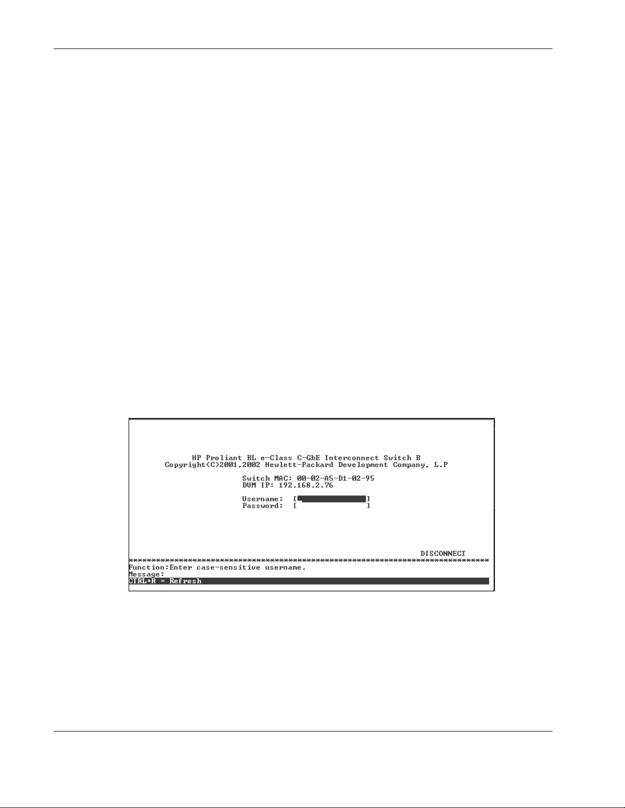
To log on for the first time:
1. Leave the Username field blank and press the Tab key.
2. Leave the Password field blank and press the Enter key. The main menu for the switch
module is displayed.
NOTE: Subsequent users will type their user name and password, then press the Enter key.
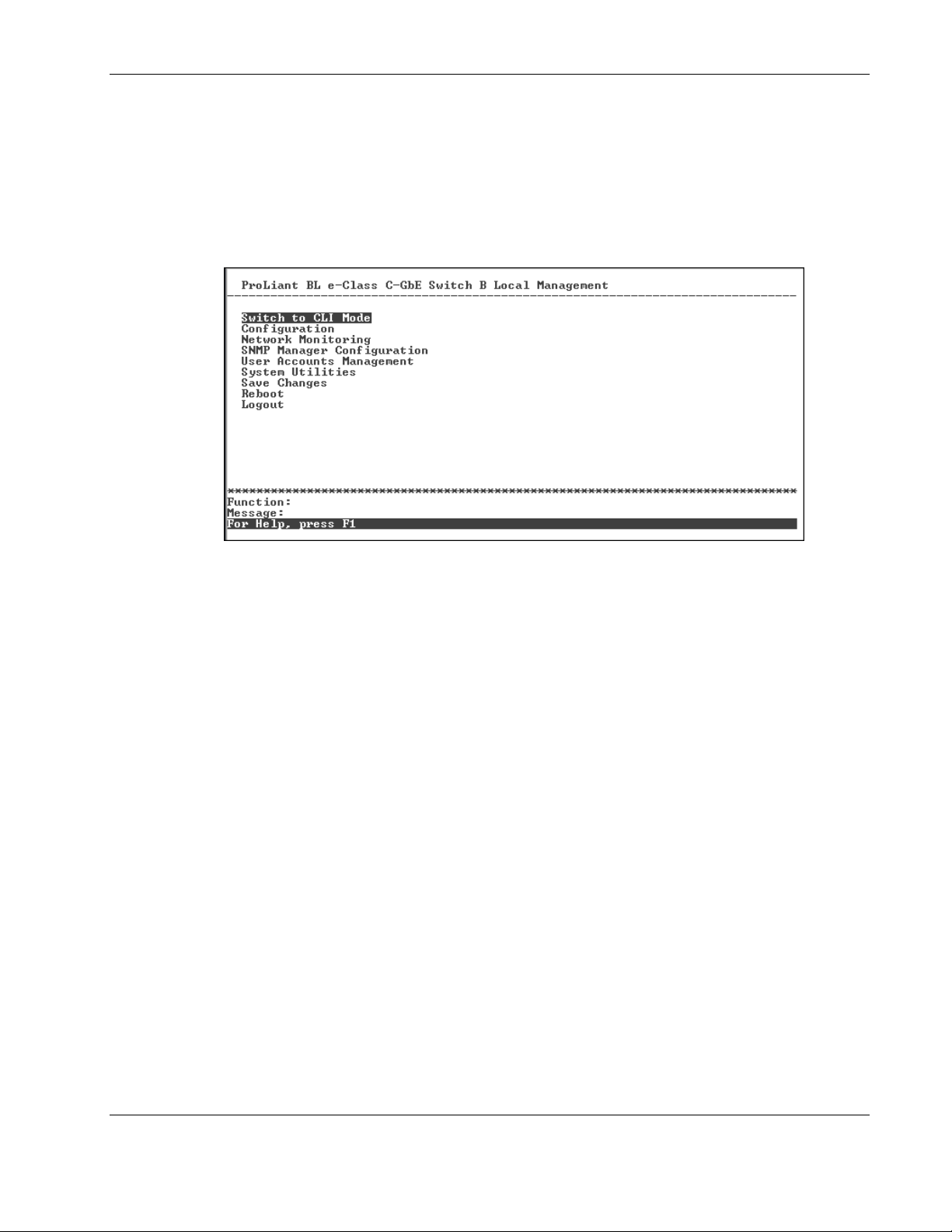
The main menu displays the major categories for switch management.
Moving Between the Console Management Interfaces
The menu-driven interface is the factory default setting. To access the command line
interface (CLI) from the menu-driven interface, highlight the Switch to CLI Mode option on
the main menu and then press the Enter key. The command line prompt for the CLI will
display.
To access the menu-driven interface from the CLI, type the following command at the
command line prompt and press the Enter key:
menu
Using the Menu-driven Interface
The menu-driven interface provides many features that make configuring the switch module
and navigating through the system easy.
HP ProLiant BL e-Class C-GbE Interconnect Switch Menu-driven Interface Reference Guide 1-3
HP CONFIDENTIAL Codename: DeLorean Part Number: 322858-001 Last Saved On: 2/4/03 11:53 AM

Overview
Navigation Features
Use the features in Table 1-1 to navigate through the screens.
Table 1-1: Menu-driven interface Navigation
To Action
Toggle between the field options Highlight items in <angle brackets>, and then press the
Enter data in a field Highlight the item in [square brackets], and then type in
Execute a command Highlight the command displayed in UPPERCASE
Move between fields on a screen
Display the previous screen
Display the main menu
Refresh the screen display
Display the next page of information
Display the previous page of information
spacebar.
the new data.
letters, and then press the Enter key.
Press the Page Up and Page Down keys, the left and
right arrow keys, the Tab key, or the Backspace key.
Press the Esc key.
Press the Ctrl+T keys.
Press the Ctrl+R keys.
Press the N key.
Press the P key.
Help and System Messages
The bottom section of each screen displays field-level help and system messages.
• • Function—Displays field-level help.
Message—Displays system messages.
Configuring the Switch Modules
After logging on to the interconnect switch for the first time, perform the following tasks for
each switch module:
1. Configure the IP address
2. Set up users, passwords, and access privileges
3. Change default SNMP community strings for read/write and read-only
For information on how to configure these and other interconnect switch features, refer to
Chapter 2.
NOTE: After configuring the IP address on the switch module, the switch module can be accessed
using Telnet, SNMP, or a Web browser. Refer to the section, “Configuring the Remote Management IP
Interface Settings,” in Chapter 2 for information on how to set up the IP address.
1-4 HP ProLiant BL e-Class C-GbE Interconnect Switch Menu-driven Interface Reference Guide
HP CONFIDENTIAL Codename: DeLorean Part Number: 322858-001 Last Saved On: 2/4/03 11:53 AM

Configuring the Switch Modules using the Menu-driven
Interface
Overview
This chapter describes how to configure the switch modules from the menu-driven interface.
Saving Changes
The switch module has two types of memory: dynamic RAM and non-volatile RAM
(NVRAM). Restarting the switch module erases all configuration settings in RAM and
reloads the stored settings from NVRAM. Thus, it is necessary to save all configuration
setting changes to NVRAM before rebooting the switch module.
After the configuration settings have been saved to NVRAM, they become the current
runtime settings for the switch module. These settings are then used every time the switch
module is rebooted.
2
Configuration changes are made effective on a screen by highlighting APPLY, then pressing
the Enter key. When this is done, the settings are immediately applied to the switching
software in RAM.
HP ProLiant BL e-Class C-GbE Interconnect Switch Menu-driven Interface Reference Guide 2-1
HP CONFIDENTIAL Codename: DeLorean Part Number: 322858-001 Last Saved On: 2/4/03 11:56 AM
Configuring the Switch Modules using the Menu-driven Interface
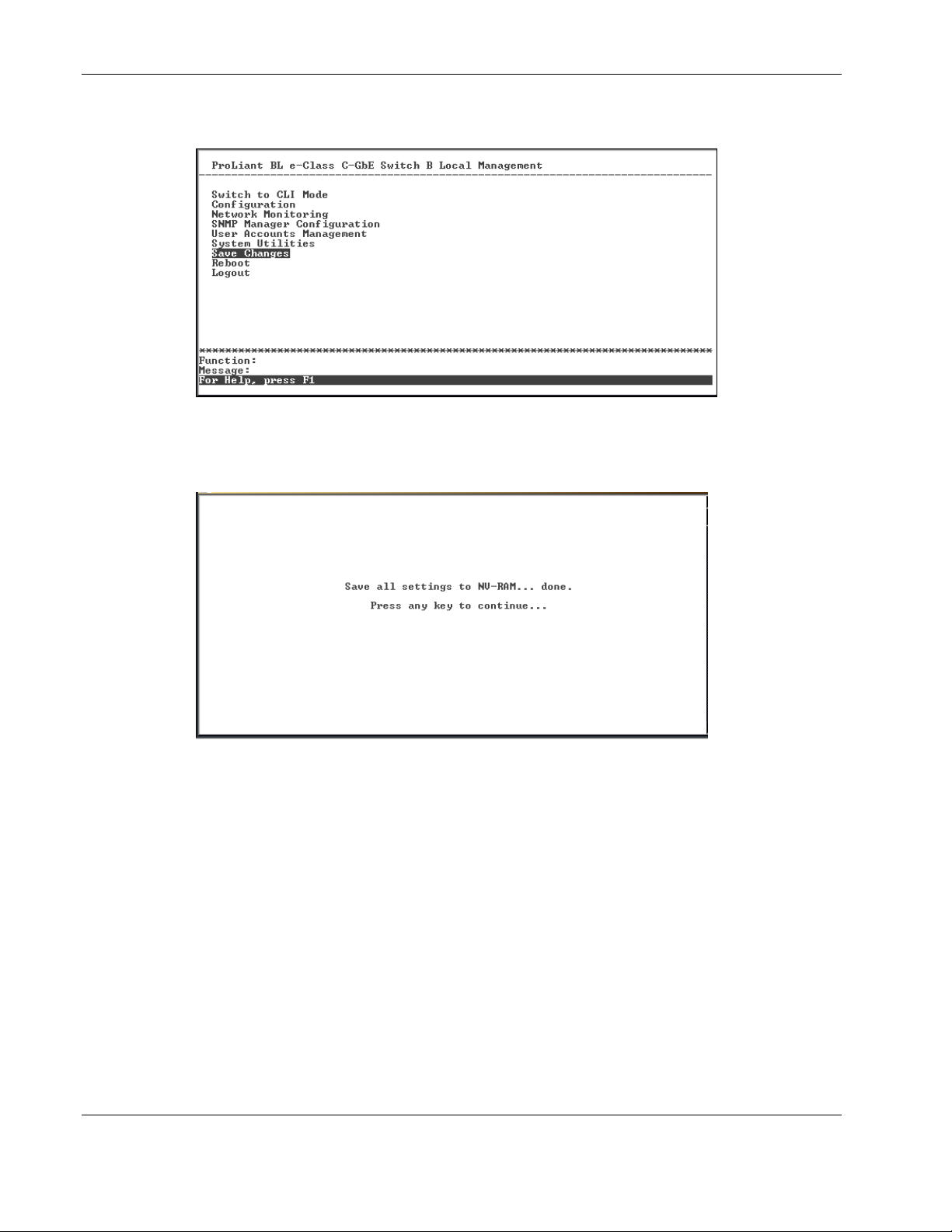
To retain any configuration changes permanently:
1. Highlight Save Changes on the main menu.
2. Press the Enter key. The following screen is displayed to verify that your new settings
have been saved to NVRAM.
After the configuration settings have been saved to NVRAM, they become the default
settings for the switch module. These settings are then used every time the switch module is
rebooted.
IMPORTANT: After saving your final configuration, HP highly recommends that you save the
configuration image to TFTP server storage. Refer to the “Saving Settings to TFTP Server” section for
more information.
2-2 HP ProLiant BL e-Class C-GbE Interconnect Switch Menu-driven Interface Reference Guide
HP CONFIDENTIAL Codename: DeLorean Part Number: 322858-001 Last Saved On: 2/4/03 11:56 AM

Managing User Accounts
After logging on to the interconnect switch for the first time, you need to set up at least one
user account with Root privileges. You can set up a maximum of eight users on a switch
module.
There are three levels of user privileges: Root, User+, and User. Some menu selections
available to users with Root privileges may not be available to those with User+ and User
privileges.
The following table summarizes the user privileges.
Table 2-1: User Privileges
Privilege Root User+ User
Configuration Yes Read-only Read-only
Network Monitoring Yes Read-only Read-only
Community Strings and Trap Stations Yes Read-only Read-only
Update Firmware and Configuration Files Yes No No
System Utilities Yes Ping-only Ping-only
Factory Reset Yes No No
Reboot Switch Yes Yes No
Add/Update/Delete User Accounts Yes No No
View User Accounts Yes No No
Configuring the Switch Modules using the Menu-driven Interface
Adding a User Account
To create a new user account:
1. Highlight User Accounts Management on the main menu.
HP ProLiant BL e-Class C-GbE Interconnect Switch Menu-driven Interface Reference Guide 2-3
HP CONFIDENTIAL Codename: DeLorean Part Number: 322858-001 Last Saved On: 2/4/03 11:56 AM
Configuring the Switch Modules using the Menu-driven Interface
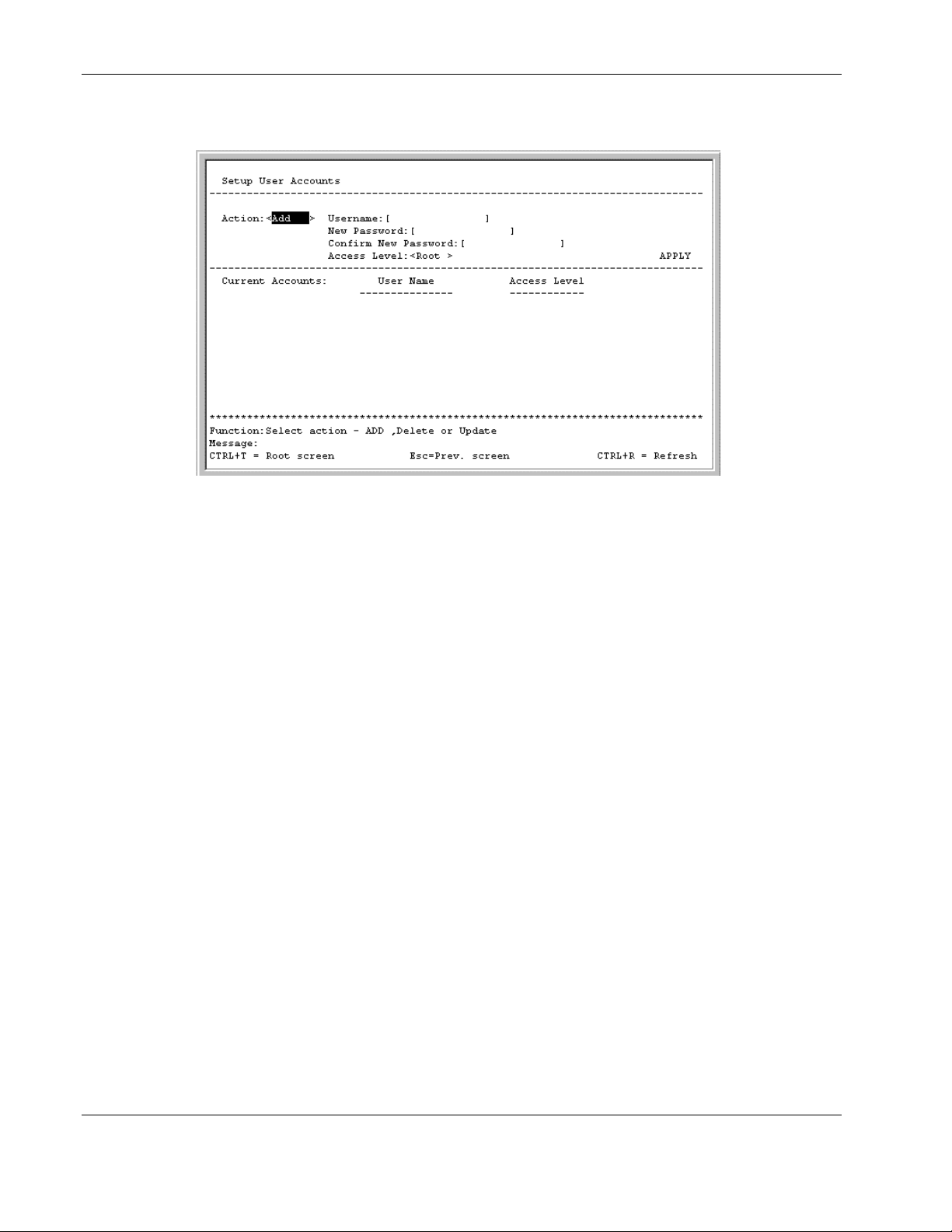
2. Press the Enter key. The Setup User Accounts screen is displayed.
3. Using the spacebar, toggle the Action field to Add.
4. Type the user’s name in the Username field.
5. Type an initial password for the user in the New Password field.
IMPORTANT: Passwords used to access the switch module are case-sensitive.
6. Type the new password a second time in the Confirm New Password field.
7. Using the spacebar, toggle the Access Level field to select the user’s access privilege.
8. Highlight APPLY.
9. Press the Enter key to make the user addition effective. A listing of all current user
accounts and access levels is displayed.
IMPORTANT: APPLY makes changes to the switch configuration for the current session only.
You must enter all permanent changes, including user additions or updates, into non-volatile RAM
(NVRAM) using the Save Changes option on the main menu. Refer to the “Saving Changes”
section for more information.
10. Press the Esc key to return to the main menu. Use the Save Changes option to save the
changes into non-volatile RAM.
2-4 HP ProLiant BL e-Class C-GbE Interconnect Switch Menu-driven Interface Reference Guide
HP CONFIDENTIAL Codename: DeLorean Part Number: 322858-001 Last Saved On: 2/4/03 11:56 AM
Updating User Account Information
To update a user password or privilege level:
1. Highlight User Accounts Management on the main menu.
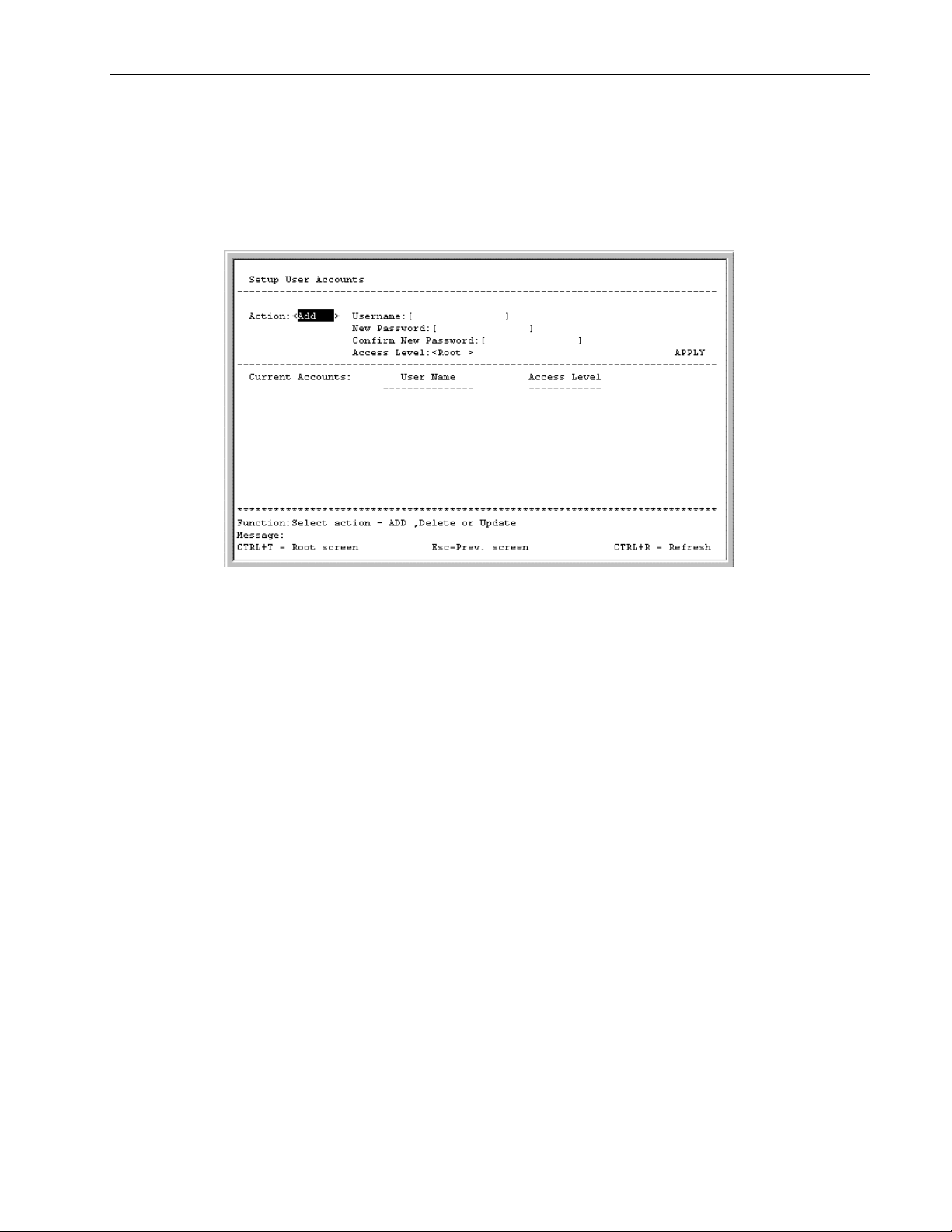
2. Press the Enter key. The Setup User Accounts screen is displayed.
Configuring the Switch Modules using the Menu-driven Interface
3. Toggle the Action field to Update.
4. Type the user name for the account you want to change in the Username field.
5. If the password is to be changed, type the new password in the New Password field.
6. Type the new password again in the Confirm New Password field.
7. If the privilege level is to be changed, toggle the Access Level field until the appropriate
level is displayed—Root, User+, or User.
8. Highlight APPLY.
9. Press the Enter key to make the change effective.
IMPORTANT: To save the configuration settings permanently, you must enter them into NVRAM
using the Save Changes option on the main menu. Refer to the “Saving Changes” section for
more information.
HP ProLiant BL e-Class C-GbE Interconnect Switch Menu-driven Interface Reference Guide 2-5
HP CONFIDENTIAL Codename: DeLorean Part Number: 322858-001 Last Saved On: 2/4/03 11:56 AM

Configuring the Switch Modules using the Menu-driven Interface
Displaying User Account Information
To view the current user accounts:
1. Highlight User Accounts Management on the main menu.
2. Press the Enter key. The Setup User Accounts screen displays a list of all current user
accounts.
Deleting a User Account
To prevent accidental deletion of all of the users with Root privilege, the menu-driven
interface does not allow you delete the current logged-on user.
To delete a user account:
1. Highlight User Accounts Management on the main menu.
2. Press the Enter key. The Setup User Accounts screen displays a list of all current user
accounts.
3. Toggle the Action field to Delete.
4. Type the user name in the Username field.
5. Highlight APPLY.
6. Press the Enter key.
IMPORTANT: To save the configuration settings permanently, you must enter them into NVRAM
using the Save Changes option on the main menu. Refer to the “Saving Changes” section for
more information.
Configuring the Remote Management IP Interface Settings
Each switch module must be assigned its own IP address, which is used for communication
with an SNMP network manager or other TCP/IP application (for example Web or TFTP).
The factory default is set for the switch module to automatically obtain the IP address using
DHCP service from a DHCP server on the attached network. You can also manually change
the default switch IP address to meet the specification of your networking address scheme. If
you select the manual mode and do not assign the IP address, the system assigns a default IP
address for Switch A as 10.90.90.90 and for Switch B as 10.90.90.91. The system also
assigns a default subnet mask of 255.0.0.0.
The switch module IP interface is also assigned a unique MAC address by the factory. This
MAC address cannot be changed and can be found on the initial boot console screen and
Logon screen, or by accessing basic switch information. Refer to the “Displaying Basic
Interconnect Switch Information” section later in this chapter.
2-6 HP ProLiant BL e-Class C-GbE Interconnect Switch Menu-driven Interface Reference Guide
HP CONFIDENTIAL Codename: DeLorean Part Number: 322858-001 Last Saved On: 2/4/03 11:56 AM

Configuring the Switch Modules using the Menu-driven Interface
In addition, you can
•
Set an IP address for a default gateway. This becomes necessary when the network
management station is located on a different IP network from the switch module, making
it necessary for management packets to go through a router to reach the network
manager, and vice-versa.
•
Set a list of up to eight secure IP addresses of network management stations that are
allowed to manage the interconnect switch. Only those network management stations can
access the switch management inerfaces once set.
•
Set a management VLAN ID (VID) for the IP interface so that the interconnect switch
can be accessed from the designated management VLAN.
•
Change the default SNMP community strings in the switch module and set the access
rights of these community strings.
Setting the Remote Management IP Interface Settings
To access and manage the interconnect switch from an SNMP-based Network Management
System, or by using the Telnet protocol or the Web, you must first configure the remote
management IP interface parameters.
The IP address can be assigned by one of the following methods:
•
Manual—This option allows you to manually configure an IP address, subnet mask, and
default gateway for the switch module.
•
BOOTP—This option configures the switch to send out a BOOTP broadcast request for
IP information. The BOOTP protocol allows IP addresses, network masks, and default
gateways to be assigned by a central BOOTP server attached to the same network to
which the interconnect switch is connected.
•
DHCP—This option configures the switch to send out a DHCP broadcast request. The
DHCP protocol allows IP addresses, network masks, and default gateways to be assigned
by a DHCP server attached to the same network to which the interconnect switch is
connected. DHCP protocol is the factory default mode.
HP ProLiant BL e-Class C-GbE Interconnect Switch Menu-driven Interface Reference Guide 2-7
HP CONFIDENTIAL Codename: DeLorean Part Number: 322858-001 Last Saved On: 2/4/03 11:56 AM
Configuring the Switch Modules using the Menu-driven Interface
To set up the switch module for remote management:
1. Highlight Configure IP Address from the Configuration menu.
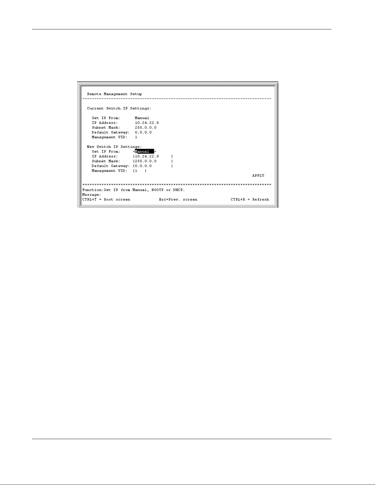
2. Press the Enter key. The following screen is displayed.
The Remote Management Setup screen lets you specify how the switch module will be
assigned an IP address, which allows an in-band network management system (for
example, Telnet) client to find it on the network.
The fields listed under the Current Switch IP Settings heading are those that are
currently being used by the switch module. Those fields listed under the New Switch IP
Settings heading are those which will be used after the switch module has been rebooted.
3. Toggle the Get IP From field to choose from Manual, BOOTP, or DHCP. This action
selects how the switch module will be assigned an IP address.
— BOOTP—The switch module sends out a BOOTP broadcast request. The BOOTP
protocol allows IP addresses, network masks, and default gateways to be assigned by
a central BOOTP server. If this option is set, the switch module first looks for a
BOOTP server to provide it with this information.
— DHCP—The switch module sends out a DHCP broadcast request. The DHCP
protocol allows IP addresses, network masks, and default gateways to be assigned by
a DHCP server. If this option is set, the switch module first looks for a DHCP server
to provide it with this information.
— Manual—This option allows the entry of an IP address, subnet mask, and default
gateway for the switch module. The data in these fields should be of the form
xxx.xxx.xxx.xxx, where each xxx is a number between 0 and 255. This address should
be a unique address on the network assigned for use by the Network Administrator.
The fields that require entries under this option include:
— Subnet Mask—A Bitmask that determines the extent of the subnet that the
switch module is on. The value should be 255.0.0.0 for a Class A network,
255.255.0.0 for a Class B network, and 255.255.255.0 for a Class C network, but
custom subnet masks are allowed.
2-8 HP ProLiant BL e-Class C-GbE Interconnect Switch Menu-driven Interface Reference Guide
HP CONFIDENTIAL Codename: DeLorean Part Number: 322858-001 Last Saved On: 2/4/03 11:56 AM

Configuring the Switch Modules using the Menu-driven Interface
— Default Gateway—An IP address that determines where packets with a
destination address outside the current subnet should be sent. This is usually the
address of a router or a host acting as an IP gateway. If your network is not part
of an intranet, or you do not want the switch module to be accessible outside your
local network, you can leave this field blank.
If you select Manual, type the appropriate data into the IP Address, Subnet Mask, and
Default Gateway fields.
4. Type the VLAN ID (VID) of a VLAN that will have access to the Telnet manager in the
Management VID field. This ID will be the VID of the VLAN on which a management
station is located. Management of the switch module using Telnet or SNMP will be
isolated to this VLAN.
5. Highlight APPLY.
6. Press the Enter key to make the change effective.
IMPORTANT: To save the configuration settings permanently, you must enter them into NVRAM
using the Save Changes option on the main menu. Refer to the “Saving Changes” section earlier
in this chapter.
Displaying Basic Interconnect Switch Information
You can display basic information about the interconnect switch including the type of switch
and the MAC address (assigned by the factory and unchangeable). In addition, the boot
PROM and firmware version numbers display. This information is helpful in monitoring
PROM and firmware updates.
In addition, you can display advanced switch information including global settings for IGMP
snooping, GVRP, Telnet status, Web status, SNTP, and others.
To configure and display the interconnect switch information and advanced settings:
1. Highlight Configure Switch Information and Advanced Settings from the
Configuration menu.
HP ProLiant BL e-Class C-GbE Interconnect Switch Menu-driven Interface Reference Guide 2-9
HP CONFIDENTIAL Codename: DeLorean Part Number: 322858-001 Last Saved On: 2/4/03 11:56 AM
Configuring the Switch Modules using the Menu-driven Interface
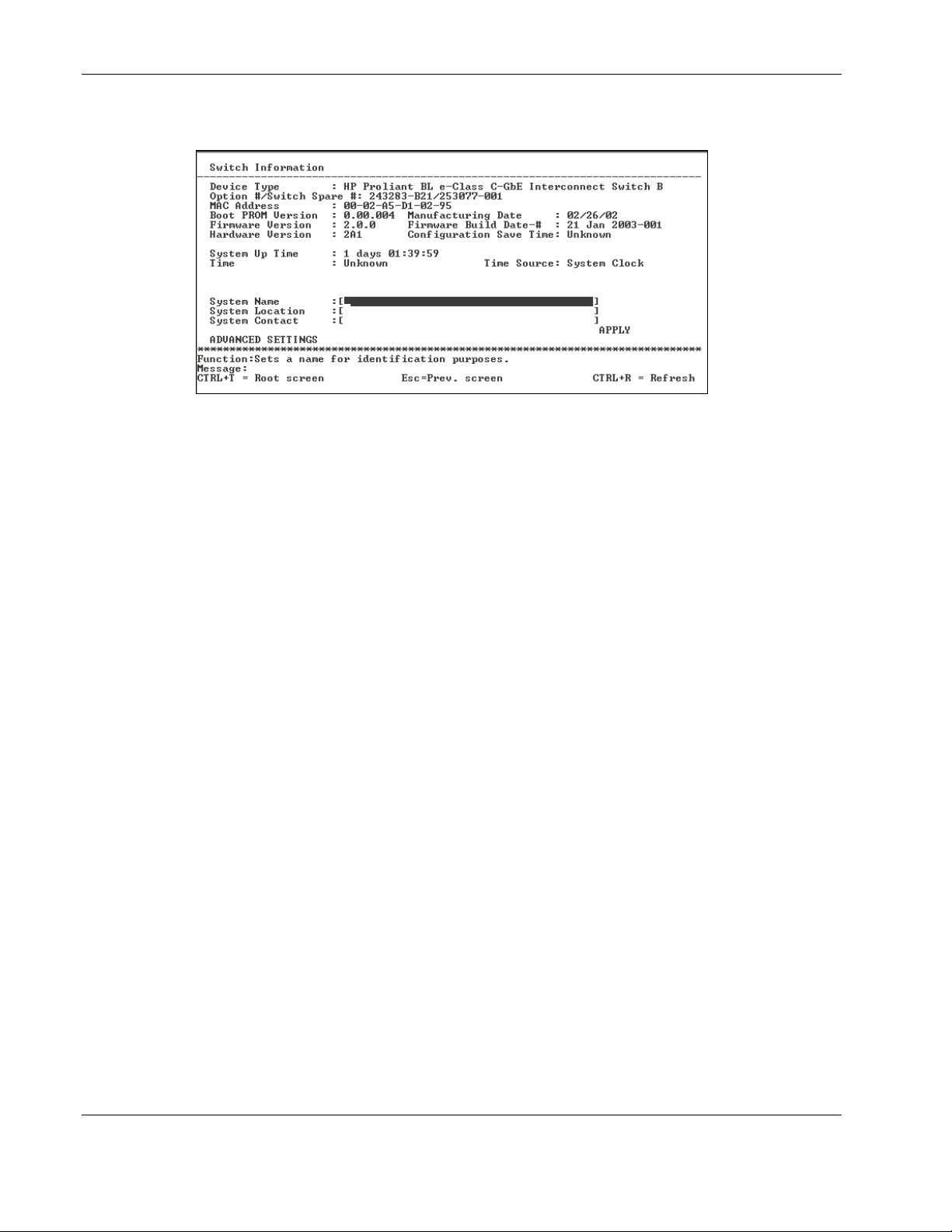
2. Press the Enter key. The following screen is displayed.
The Switch Information menu displays general information about the interconnect
switch including:
— Device Type—Identifies the interconnect switch name and module (Switch A or
Switch B).
— Option #/Switch Spare #—Identifies the option number and spare number for the
interconnect switch.
— MAC Address—Identifies the unique MAC address assigned by the factory. This
MAC address cannot be changed.
— Boot PROM Version—Identifies the version number of Boot PROM code installed
on the interconnect switch.
— Manufacturing Date—Identifies the date the interconnect switch was manufactured.
— Firmware Version—Identifies the version number of interconnect switch firmware.
— Firmware Build Date-#—Identifies the firmware build date and build number.
— Hardware Version—Identifies the version number of interconnect switch hardware
build.
— Configuration Save Time—Identifies the date and time the current settings were
saved to the configuration file.
— System Up Time—Identifies the time the switch booted up, if the current time has
been set on the switch module. If the current time has never been set up on the
interconnect switch, this field identifies the time since the switch module was booted
up.
— Time— Displays the current real time set on the switch module. If the current time
has never been set up on the interconnect switch, “Unknown” will be displayed.
— Time Source—Identifies the method in which the interconnect switch gets the
current time information: System Clock, Primary SNTP Server, or Secondary SNTP
Server.
2-10 HP ProLiant BL e-Class C-GbE Interconnect Switch Menu-driven Interface Reference Guide
HP CONFIDENTIAL Codename: DeLorean Part Number: 322858-001 Last Saved On: 2/4/03 11:56 AM
Configuring the Switch Modules using the Menu-driven Interface
To complete the basic information:
1. Type the name of the system in the System Name field.
2. Type the location of the system in the System Location field.
3. Type the name and telephone number of the System Administrator in the System
Contact field. HP recommends that the person who is responsible for the maintenance of
the network system on which this interconnect switch is installed be listed here.
4. Highlight APPLY.
5. Press the Enter key to make the change effective.
IMPORTANT: To save the configuration settings permanently, you must enter them into NVRAM
using the Save Changes option on the main menu. Refer to the “Saving Changes” section earlier
in this chapter.
Configuring Advanced Switch Module Features
The menu-driven interface allows you to easily set advanced switch features including global
settings for IGMP snooping, GVRP, Telnet status, Web status, SNTP, and others.
To configure advanced switch module features:
1. Highlight ADVANCED SETTINGS at the bottom of the Switch Information menu.
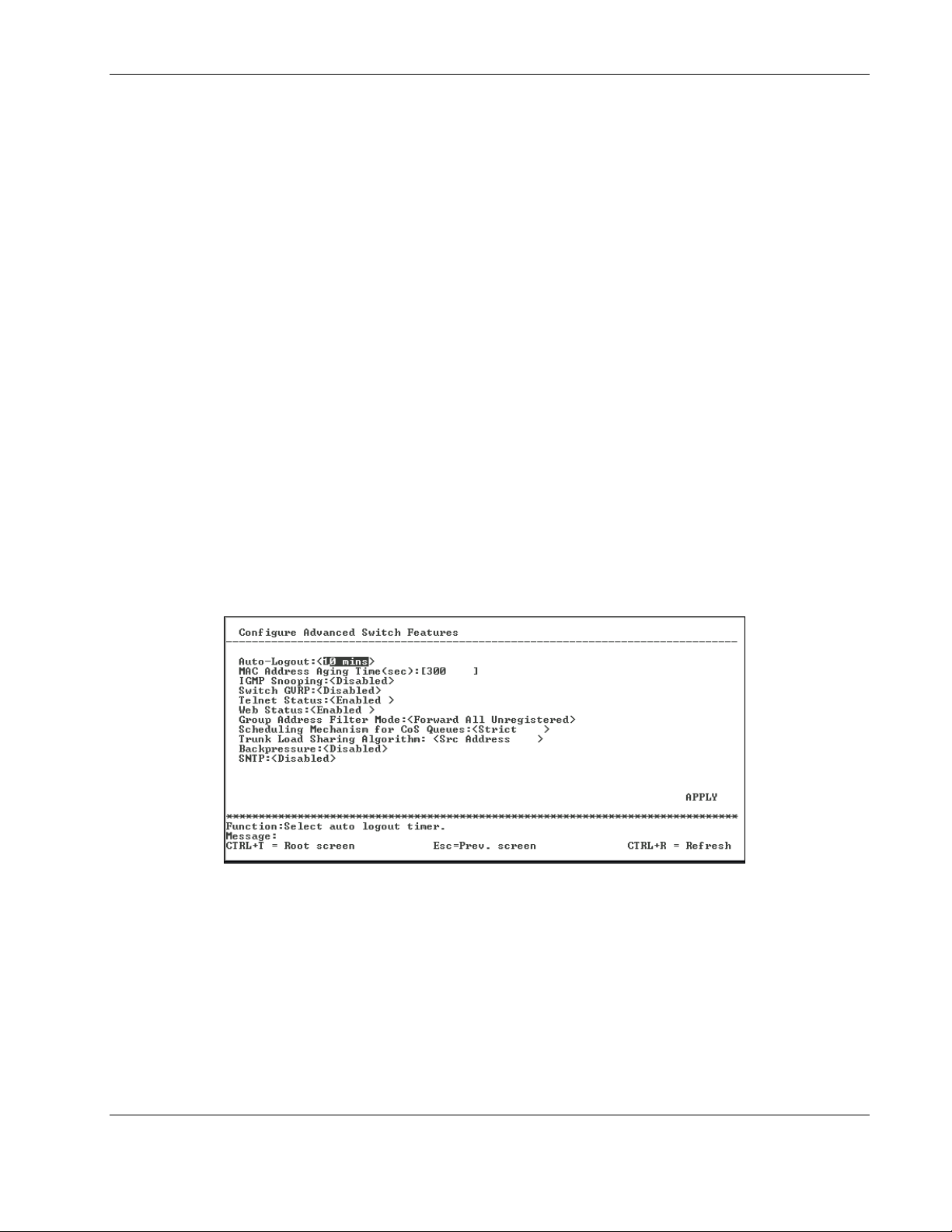
2. Press the Enter key. The following screen is displayed.
This screen allows you to set the following features:
— Auto-Logout—Toggle to select the time the RS-232 console and Telnet management
interface can be idle before the interconnect automatically logs out the user. The
options are 2 mins, 5 mins, 10 mins, 15 mins, and Never. Never indicates never
timing out. The default is 10 minutes.
— MAC Address Aging Time (sec)—Type the length of time a learned MAC address
remains in the forwarding table without being seen as a source (that is, how long a
learned MAC address is allowed to remain idle before deleting from the address
table).
HP ProLiant BL e-Class C-GbE Interconnect Switch Menu-driven Interface Reference Guide 2-11
HP CONFIDENTIAL Codename: DeLorean Part Number: 322858-001 Last Saved On: 2/4/03 11:56 AM

Configuring the Switch Modules using the Menu-driven Interface
The switch module enters into its forwarding table the mapping between the MAC
address of the device and the Ethernet port to which the device is attached. This
information is used to forward packets. This reduces the traffic congestion on the
network, because packets are forwarded to the destination port only, instead of being
forwarded to all ports.
The MAC address aging timer prunes the forwarding table addresses entries that are
no longer used. Dynamic forwarding table entries, which are made up of MAC
addresses and their associated port numbers, are deleted from the table if they are not
seen within the aging timeout. The aging time can be from 10 to 1,000,000 seconds
with a default value of 300 seconds. A very long aging time can result in dynamic
forwarding table entries that are out-of-date or no longer are used.
If the aging time is too short, however, many entries may be aged out too soon. This
will result in a high percentage of received packets whose destination addresses
cannot be found in the forwarding table. In this case the switch module will broadcast
the packet to all ports, negating many of the benefits of having a switch.
Static forwarding entries are not affected by the aging time.
— IGMP Snooping—Toggle to enable or disable Internet Group Management Protocol
(IGMP) Snooping. IGMP snooping enables the switch module to register IGMP
packets being forwarded through the switch in order to obtain multicast membership
information from them and learn which ports are attached to which multicast group
members. For additional information, refer to the “Configuring IGMP Snooping”
section later in this chapter.
— Switch GVRP—Toggle to enable or disable GARP VLAN Registration Protocol
(GVRP) on the interconnect switch. GVRP allows dynamic propagation of VLAN
registration information across the GVRP-enabled switches on the same network. For
additional information, refer to the “Configuring GVRP” section later in this chapter.
— Telnet Status—Toggle to enable or disable access to the interconnect switch over
the network using the Telnet protocol.
— Web Status—Toggle to enable or disable use of a Web-based browser to manage the
interconnect switch.
— Group Address Filter Mode—Toggle to select the IGMP group address filter mode
for forwarding multicast packets. The options are Forward All, Forward All
Unregistered, and Filtered All Unregistered.
— Scheduling Mechanism for CoS Queues—Toggle to select the Class of Service
queue scheduling option: RoundRobin or Strict. If you select Strict, when the
highest priority queue is full, those packets are the first to be forwarded. If you select
RoundRobin, the forwarding is based on the settings made on the Class of Service
Configuration screen. For more information, refer to the “Configuring the Class of
Service, Default Port Priority, and Traffic Class” section later in this chapter.
— Trunk Load Sharing Algorithm—Toggle to select how port load sharing will be
determined. The multitrunk load sharing options are destination address, source
address, and source and destination address.
2-12 HP ProLiant BL e-Class C-GbE Interconnect Switch Menu-driven Interface Reference Guide
HP CONFIDENTIAL Codename: DeLorean Part Number: 322858-001 Last Saved On: 2/4/03 11:56 AM
— Backpressure—Toggle to enable or disable backpressure flow control in and out of
the switch. When backpressure is enabled and there is incoming traffic congestion on
a 10/100 port, the receiving port sends a request to the transmitting port. The
transmitting port acknowledges the request and stops sending packets for a random
amount of time, before it starts sending again.
— SNTP—Toggle to enable or disable Simple Network Time Protocol (SNTP). For
additional information, refer to the “Configuring the Switch Module Date and Time”
section later in this chapter.
3. After making your changes, highlight APPLY, then press the Enter key.
IMPORTANT: To save the configuration settings permanently, you must enter them into NVRAM using
the Save Changes option on the main menu. Refer to the “Saving Changes” section earlier in this
chapter.
Configuring Port Settings
This section describes how to configure the following port settings: port name, speed/duplex
parameter, and flow control state. Refer to the “Configuring Port Security” section later in
this chapter for information on how to set the port security parameters.
Configuring the Switch Modules using the Menu-driven Interface
The speed-duplex parameter for each port can be set to 1000M/Full, 100M/Full, 100M/Half,
10M/Full, 10M/Half, or Auto. The Auto setting allows the port to automatically determine
the fastest settings that the device the port is connected to can handle.
IMPORTANT: In the forced 100M/Full, 100M/Half, 10M/Full, and 10M/Half modes, auto MDI-X is
disabled and a cross-over cable must be used.
To configure ports:
1. Highlight Configure Ports from the Configuration menu.
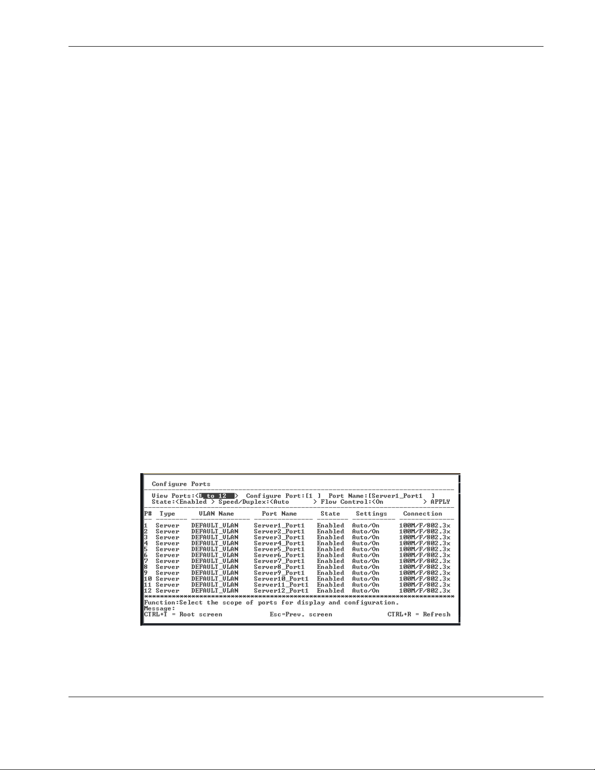
2. Press the Enter key. The following screen is displayed.
The Configure Ports screen allows you to configure the name, speed-duplex, and flow
control for each port
HP ProLiant BL e-Class C-GbE Interconnect Switch Menu-driven Interface Reference Guide 2-13
HP CONFIDENTIAL Codename: DeLorean Part Number: 322858-001 Last Saved On: 2/4/03 11:56 AM

Configuring the Switch Modules using the Menu-driven Interface
3. Toggle the View Ports field, using the space bar, to display the configuration of either
Ports 1 through 12, Ports 13 through 24, or Ports 25 through 26.
4. Type the port number in the Configure Port field.
5. Type the port name in the Port Name field.
6. Toggle the State field to either enable or disable a given port.
7. Toggle the Speed/Duplex field to select the speed and duplex/half-duplex state of the
port. Auto means auto-negotiation between 10 and 100 Mb/s devices, in full- or halfduplex mode. The Auto setting allows the port to automatically determine the fastest
settings the device the port is connected to can handle. The other options are 100M/Full,
100M/Half, 10M/Full, or 10M/Half. There is no automatic adjustment of port settings
with any option other than Auto.
8. Toggle Flow Control to On or Off when.
9. Highlight APPLY.
10. Press the Enter key to make the change effective.
IMPORTANT: To save the configuration settings permanently, you must enter them into NVRAM
using the Save Changes option on the main menu. Refer to the “Saving Changes” section earlier
in this chapter.
Configuring Bandwidth
The GbE Interconnect Switch allows you to set a bandwidth limitation that restricts the
ingress (receiving) and egress (transmitting) packet rate for each port. If the packet rate
exceeds the allowed bandwidth rate, the excess packets will be dropped.
Bandwidth is configured in 1 to 127 units. Each unit is 117,481 bytes per second (around 0.94
Mb/s) for ports 1-26 and 939,850 bytes (about 7.52 Mb/s) for optional ports.
To configure bandwidth:
1. Highlight Configure Bandwidth on the Configuration menu.
2-14 HP ProLiant BL e-Class C-GbE Interconnect Switch Menu-driven Interface Reference Guide
HP CONFIDENTIAL Codename: DeLorean Part Number: 322858-001 Last Saved On: 2/4/03 11:56 AM
 Loading...