

Page 1

HP ProLiant BL e-Class
Integrated Administrator
User Guide
May 2003 (Fourth Edition)
Part Number 249070-004
Page 2

© 2003 Hewlett-Packard Development Company, L.P.
Microsoft® and Windows® are U.S. registered trademarks of Microsoft Corporation.
Hewlett-Packard Company shall not be liable for technical or editorial errors or omissions
contained herein. The information in this document is provided “as is” without warranty of
any kind and is subject to change without notice. The warranties for HP products are set forth
in the express limited warranty statements accompanying such products. Nothing herein
should be construed as constituting an additional warranty.
Confidential computer software. Valid license from HP required for possession, use or
copying. Consistent with FAR 12.211 and 12.212, Commercial Computer Software, Computer
Software Documentation, and Technical Data for Commercial Items are licensed to the U.S.
Government under vendor's standard commercial license.
HP ProLiant BL e-Class Integrated Administrator User Guide
May 2003 (Fourth Edition)
Part Number 249070-004
Page 3

Contents
About This Guide
Audience Assumptions...................................................................................................... ix
Important Safety Information ............................................................................................ ix
Symbols on Equipment ..................................................................................................... ix
Symbols in Text.................................................................................................................xi
Related Documents........................................................................................................... xii
Getting Help ..................................................................................................................... xii
Technical Support ...................................................................................................... xii
HP Website ............................................................................................................... xiii
Authorized Reseller .................................................................................................. xiii
Reader’s Comments ........................................................................................................ xiii
Chapter 1
HP ProLiant BL e-Class System Software Features
ProLiant BL e-Class Integrated Administrator................................................................ 1-1
Integrated Administrator Features................................................................................... 1-2
Overview of ProLiant BL e-Class Software Tools.......................................................... 1-5
Chapter 2
Getting Started
Reviewing Configuration Tools and Information ........................................................... 2-1
Identifying the Integrated Administrator Connectors...................................................... 2-2
Determining the Integrated Administrator’s Initial IP Address ...................................... 2-4
Requirements for Local Client Devices .................................................................... 2-4
Default Values for the Integrated Administrator ...................................................... 2-5
Determining the IP Address using the Local Console .............................................. 2-5
Setting Up the Web-Based User Interface....................................................................... 2-7
HP ProLiant BL e-Class Integrated Administrator User Guide iii
Page 4

Contents
Additional Steps.............................................................................................................2-11
Help................................................................................................................................2-11
Chapter 3
Web-Based User Interface
Accessing the Web-Based User Interface........................................................................3-2
Web-Based Navigation .................................................................................................... 3-3
Top Panel...................................................................................................................3-3
Left Panel ..................................................................................................................3-5
Deck Panel.................................................................................................................3-6
Enclosure Tab ..................................................................................................................3-6
Enclosure Information...............................................................................................3-7
Network Configuration............................................................................................3-13
SNMP Configuration...............................................................................................3-16
Virtual Buttons ........................................................................................................3-19
System Log.............................................................................................................. 3-21
Bays Tab ........................................................................................................................3-22
Bay List ...................................................................................................................3-22
Bay Information ......................................................................................................3-26
Remote Console ......................................................................................................3-28
Virtual Buttons ........................................................................................................3-30
Console Log...................................................................................................................3-31
Administration Tab ........................................................................................................ 3-32
User List ..................................................................................................................3-33
Group List ...............................................................................................................3-35
Add User .................................................................................................................3-36
Add Group...............................................................................................................3-39
View/Modify User...................................................................................................3-42
View/Modify Group................................................................................................ 3-42
Event List Tab................................................................................................................ 3-43
Interconnect Tab ............................................................................................................3-45
Chapter 4
Command Line Interface
Accessing the Command Line Interface ..........................................................................4-2
Accessing Remotely through the Management Connector .......................................4-2
Accessing Locally through the Console Connector ..................................................4-2
Operating the Command Line Interface ..........................................................................4-3
iv HP ProLiant BL e-Class Integrated Administrator User Guide
Page 5

General Commands................................................................................................... 4-3
General Management Commands............................................................................. 4-4
User Account Commands ......................................................................................... 4-7
Enclosure Network Configuration Commands ....................................................... 4-12
Enclosure Management Commands ....................................................................... 4-16
Server Bay Management Commands...................................................................... 4-20
Command Line Event Messages............................................................................. 4-25
Functionality Exclusive to the Command Line Interface.............................................. 4-27
Chapter 5
Setting Up the System
User Permissions ............................................................................................................. 5-3
Customizing the Enclosure Settings................................................................................ 5-4
Changing the Administrator Password ..................................................................... 5-4
Modifying Enclosure and Rack Names .................................................................... 5-5
Modifying the Asset Tag Number ............................................................................ 5-7
Modifying the Date and Time................................................................................... 5-8
Setting Up User Accounts ............................................................................................. 5-10
Adding a Group ...................................................................................................... 5-10
Adding a User ......................................................................................................... 5-14
Enabling Remote Console Sessions to Server Blades ................................................... 5-18
Setting Up AlertMail ..................................................................................................... 5-22
E-mail Alerts........................................................................................................... 5-22
Setting Up IP Security................................................................................................... 5-24
Setting Up Automatic Time Configuration (NTP)........................................................ 5-25
Configuring SNMP Support .......................................................................................... 5-26
Entering a Community String ................................................................................. 5-26
Modifying the System Location.............................................................................. 5-27
Modifying the System Contact Information ........................................................... 5-28
Adding Trap Targets............................................................................................... 5-28
Removing Trap Targets .......................................................................................... 5-29
Contents
Chapter 6
Performing Common Administrative Tasks
Managing Server Blade Bays .......................................................................................... 6-2
Opening a Remote Console Session to a Server Blade............................................. 6-2
Accessing the ROM-Based Setup Utility for a Server Blade ................................... 6-4
Reviewing Activity for a Server Blade..................................................................... 6-6
HP ProLiant BL e-Class Integrated Administrator User Guide v
Page 6

Contents
Powering Off the Server Blade .................................................................................6-7
Identifying a Server Blade Using the Unit Identification LED................................. 6-9
Managing the Enclosure ................................................................................................6-11
Reviewing the Activity of the Enclosure.................................................................6-11
Identifying the Enclosure Using the Unit Identification LED.................................6-13
Generating an Enclosure Summary......................................................................... 6-14
Identifying Problem Components ...........................................................................6-16
Managing Users .............................................................................................................6-22
Modifying a User’s Rights to Server Blade Bays ...................................................6-22
Disabling and Deleting User Accounts ...................................................................6-25
Chapter 7
Performing Advanced Functions
Replicating the Configuration of the Integrated Administrator ....................................... 7-2
Administering Security Certificates................................................................................. 7-4
Creating a Certificate Request................................................................................... 7-4
Downloading a Security Certificate ..........................................................................7-4
Key-Based SSH Authentication....................................................................................... 7-5
Configuring Server Blade Boot Order .............................................................................7-7
Powering Off the Enclosure............................................................................................. 7-8
Disabling Network Protocols.........................................................................................7-10
Upgrading the Integrated Administrator Firmware .......................................................7-11
Recovering a Lost Administrator Password ..................................................................7-12
Launching Flash Disaster Recovery ..............................................................................7-13
Appendix A
Command Line Conventions
Appendix B
Error Messages
Warning Messages.......................................................................................................... B-1
Enclosure Warning Messages .................................................................................. B-2
Server Blade Bay Warning Messages ...................................................................... B-3
Administration Warning Messages .......................................................................... B-3
Error Messages ............................................................................................................... B-4
Enclosure Error Messages ........................................................................................ B-4
Server Blade Bay Error Messages............................................................................ B-4
Administration Error Messages................................................................................ B-5
vi HP ProLiant BL e-Class Integrated Administrator User Guide
Page 7

Appendix C
Troubleshooting
Appendix D
Event Details
Appendix E
Factory Default Settings
Enclosure.........................................................................................................................E-2
Users................................................................................................................................E-2
Groups .............................................................................................................................E-3
Network ........................................................................................................................... E-3
Protocol ...........................................................................................................................E-3
Appendix F
Time Zone Settings
Universal ......................................................................................................................... F-2
Africa............................................................................................................................... F-3
Asia.................................................................................................................................. F-4
Europe .............................................................................................................................F-6
Oceania............................................................................................................................ F-7
Polar ................................................................................................................................ F-9
The Americas ................................................................................................................ F-10
Contents
Appendix G
Open Source Availability
Index
HP ProLiant BL e-Class Integrated Administrator User Guide vii
Page 8
This guide provides step-by-step instructions for operation, and reference information
for advanced operation, troubleshooting, and future upgrades for the HP
ProLiant BL e-Class Integrated Administrator.
Audience Assumptions
This guide is intended for users with access to the ProLiant BL e-Class Integrated
Administrator. It assumes that the server blade system hardware is installed, and that
the user has minimal experience working with server blade systems.
About This Guide
Important Safety Information
Before installing this product, read the Important Safety Information document
included with the server.
Symbols on Equipment
The following symbols may be placed on equipment to indicate the presence of
potentially hazardous conditions:
WARNING: This symbol, in conjunction with any of the following symbols,
indicates the presence of a potential hazard. The potential for injury exists if
warnings are not observed. Consult the documentation for specific details.
HP ProLiant BL e-Class Integrated Administrator User Guide ix
Page 9
About This Guide
Weight in kg
Weight in lb
This symbol indicates the presence of hazardous energy circuits or electric
shock hazards. Refer all servicing to qualified personnel.
WARNING: To reduce the risk of injury from electric shock hazards, do not
open this enclosure. Refer all maintenance, upgrades, and servicing to
qualified personnel.
This symbol indicates the presence of electric shock hazards. The area
contains no user or field serviceable parts. Do not open for any reason.
WARNING: To reduce the risk of injury from electric shock hazards, do not
open this enclosure.
This symbol on an RJ-45 receptacle indicates a network interface connection.
WARNING: To reduce the risk of electric shock, fire, or damage to the
equipment, do not plug telephone or telecommunications connectors into this
receptacle.
This symbol indicates the presence of a hot surface or hot component. If this
surface is contacted, the potential for injury exists.
WARNING: To reduce the risk of injury from a hot component, allow the
surface to cool before touching.
These symbols, on power supplies or systems, indicate that the
equipment is supplied by multiple sources of power.
WARNING: To reduce the risk of injury from electric shock,
remove all power cords to completely disconnect power from the
system.
This symbol indicates that the component exceeds the recommended
weight for one individual to handle safely.
WARNING: To reduce the risk of personal injury or damage to the
equipment, observe local occupational health and safety requirements
and guidelines for manual material handling.
x HP ProLiant BL e-Class Integrated Administrator User Guide
Page 10
Symbols in Text
These symbols may be found in the text of this guide. They have the following
meanings.
WARNING: Text set off in this manner indicates that failure to follow directions
in the warning could result in bodily harm or loss of life.
CAUTION: Text set off in this manner indicates that failure to follow directions could
result in damage to equipment or loss of information.
IMPORTANT: Text set off in this manner presents essential information to explain a concept
or complete a task.
NOTE: Text set off in this manner presents additional information to emphasize or supplement
important points of the main text.
About This Guide
HP ProLiant BL e-Class Integrated Administrator User Guide xi
Page 11

About This Guide
Related Documents
For additional information on the topics covered in this guide, refer to the following
documentation:
• HP ProLiant BL e-Class System Maintenance and Service Guide
• HP ProLiant BL e-Class System Hardware Installation and Configuration poster
• ProLiant Integration Module for Altiris eXpress User Guide
• HP Servers Troubleshooting Guide
• HP ROM-Based Setup Utility Guide
• HP ProLiant BL e-Class C-GbE Interconnect Switch User Guide
• White paper: HP ProLiant BL e-Class System Overview and Planning
• White paper: Configuring a Preboot eXecution Environment (PXE) using Red
Hat Linux 7.2 on ProLiant Servers
• QuickSpecs
Getting Help
If you have a problem and have exhausted the information in this guide, you can get
further information and other help in the following locations.
Technical Support
In North America, call the HP Technical Support Phone Center at 1-800-652-6672.
This service is available 24 hours a day, 7 days a week. For continuous quality
improvement, calls may be recorded or monitored. Outside North America, call the
nearest HP Technical Support Phone Center. Telephone numbers for worldwide
Technical Support Centers are listed on the HP website, www.hp.com.
xii HP ProLiant BL e-Class Integrated Administrator User Guide
Page 12

Be sure to have the following information available before you call HP:
• Technical support registration number (if applicable)
• Product serial number
• Product model name and number
• Applicable error messages
• Add-on boards or hardware
• Third-party hardware or software
• Operating system type and revision level
HP Website
The HP website has information on this product as well as the latest drivers and flash
ROM images. You can access the HP website at www.hp.com.
Authorized Reseller
About This Guide
For the name of the nearest authorized reseller:
• In the United States, call 1-800-345-1518.
• In Canada, call 1-800-263-5868.
• Elsewhere, see the HP website for locations and telephone numbers.
Reader’s Comments
HP welcomes your comments on this guide. Please send your comments and
suggestions by e-mail to ServerDocumentation@hp.com.
HP ProLiant BL e-Class Integrated Administrator User Guide xiii
Page 13

HP ProLiant BL e-Class System Software
Features
The HP ProLiant BL e-Class system offers an extensive set of features and optional
tools to support effective server management and software deployment. This chapter
describes the Integrated Administrator and provides a brief overview of software
associated with the system.
ProLiant BL e-Class Integrated Administrator
The Integrated Administrator is a centralized management and monitoring system for
the ProLiant BL e-Class enclosure and server blades. The Integrated Administrator
acts as a combination terminal server and remote power controller, enabling
out-of-band, secure, serial console connections to all server blades in the enclosure.
1
The ProLiant BL e-Class Integrated Administrator is a standard component of
ProLiant BL e-Class systems. The Integrated Administrator provides enclosure
health, server blade health, and remote server manageability. Integrated
Administrator features are accessed from any network-based client. The Integrated
Administrator provides remote access to any authorized network client, sends alerts,
and provides many other server blade management functions.
The Integrated Administrator subsystem is embedded on a module included with
each interconnect tray and includes an intelligent microprocessor, secure memory,
and a dedicated network interface. This design makes the Integrated Administrator
independent of the host server and its operating system.
HP ProLiant BL e-Class Integrated Administrator User Guide 1-1
Page 14

HP ProLiant BL e-Class System Software Features
For further information associated with the Integrated Administrator, refer to:
www.compaq.com/products/servers/proliant-bl/e-class/integrated-admin.html
Integrated Administrator Features
The Integrated Administrator provides the following functionality to deliver
state-of-the-art management of the enclosure and server blades:
•
Dedicated LAN network connectivity
Each Integrated Administrator provides a dedicated network connection.
The NIC can auto-select speeds between 10 Mbps and 100 Mbps. When the
ProLiant BL e-Class C-GbE Interconnect Switch (option) is installed, the
Integrated Administrator can be configured to route through a Gigabit uplink
connector using VLANS, eliminating the need for a separate management
network.
•
SNMP alerts from Integrated Administrator to a management console
The Integrated Administrator provides notification of enclosure problems. Using
a management console, you can access certain server blade alerts, such as SNMP
and unauthorized access alerts.
•
E-mail alerts from Integrated Administrator to an e-mail account (AlertMail)
AlertMail enables the Integrated Administrator to send system events by e-mail
instead of using SNMP traps. AlertMail is completely independent from SNMP
and both can be enabled at the same time. AlertMail uses standard SMTP
commands to communicate with any SMTP capable mail server.
•
Remote access and control
The Integrated Administrator provides remote functionality to access the console
of the host server blade, change the state of the Unit Identification LED on an
enclosure and its server blades, and power up, power down, or reboot a server
blade.
The Integrated Administrator displays alerts regardless of the state of the user’s
host server blade and integrates with the Insight Manager 7 utility using SNMP
to provide alerts and diagnostics of the system.
1-2 HP ProLiant BL e-Class Integrated Administrator User Guide
Page 15

HP ProLiant BL e-Class System Software Features
If a server blade does not respond, this feature enables an administrator to initiate
a cold reboot to bring the server blade back online. The Integrated Administrator
can be used to remotely operate a power button of a server blade.
Integrated Administrator is fully accessible by means of Microsoft® Internet
Explorer and Netscape. This capability enables easy access to the features of
Integrated Administrator.
The Integrated Administrator also has a command line interface (CLI) accessible
using Secure Shell (encrypted) or Telnet (unencrypted) protocols, providing
extensive management capability to remote network users. Local users can
access the CLI by attaching a client computer (using a terminal emulator) or
terminal to the Integrated Administrator’s console (serial) port.
IMPORTANT: With a Telnet session, all dataincluding passwordsare passed as clear
text.
• User administration and security
The Integrated Administrator supports up to 25 users with customizable access
rights and login names. Groups are first assigned bays, and then users are given
membership to those groups. This group-centered methodology is designed to
facilitate user management across server blades.
Integrated Administrator provides strong security for remote management in
distributed IT environments by using industry-standard Secure Sockets Layer
(SSL) encryption of HTTP data transmitted across the network. SSL encryption
(up to 128-bit) ensures that the HTTP information is secure as it travels across
the network. All remote console data can be encrypted as well.
Integrated Administrator provides secure password encryption, tracking all login
attempts and maintaining a record of all login failures. Integrated Administrator
also provides the following additional security features:
— User actions logged in the Integrated Administrator System Log
— Login legal warning
IP Security allows an administrator to define a set of IP addresses that are the
only ones allowed to connect to the services provided (SSH, HTTP, HTTPS,
TELNET, SNMP). This means that an administrator can make sure only a certain
set of machines have access to Integrated Administrator.
HP ProLiant BL e-Class Integrated Administrator User Guide 1-3
Page 16

HP ProLiant BL e-Class System Software Features
• Automatic network configuration
The Integrated Administrator provides automatic network configuration of the IP
address and host name using Dynamic Host Configuration Protocol (DHCP) and
Dynamic DNS/WINS. Integrated Administrator comes with a default name and
DHCP client that leases an IP address from the DHCP server on the network. For
networks that do not use DHCP, the Integrated Administrator enables static IP
configuration.
• • Automatic time configuration (NTP)
Automatic time configuration allows Integrated Administrator to synchronize its
date and time with a server supporting the Network Time Protocol (NTP).
Integration with the Insight Manager 7 utility
Integrated Administrator provides full integration with the Insight Manager 7
utility under key operating environments. This integration provides:
— Support for SNMP management
Support for SNMP trap delivery to a Insight Manager 7 console
— Management processor
The Insight Manager 7 utility adds support for a new device type, the
management processor. All Integrated Administrators (in ProLiant BL
e-Class enclosures) on the network are discovered in the Insight Manager 7
utility as management processors. The management processors are associated
with the server blades they manage.
— Integrated Administrator hyperlinks
The Insight Manager 7 utility provides a hyperlink on the server device page
to launch and connect to Integrated Administrator.
— Grouping of Integrated Administrator processors
All Integrated Administrator management processors can be grouped
together logically and displayed on one page in the Insight Manager 7 utility.
This capability provides access to all Integrated Administrators on the
network from one point in Insight Manager 7.
1-4 HP ProLiant BL e-Class Integrated Administrator User Guide
Page 17

HP ProLiant BL e-Class System Software Features
For more information on the Insight Manager 7 utility, refer to the ProLiant
Essentials Foundation Pack documentation that ships with the system or refer to:
www.hp.com/servers/rdp
•
Event Notification
The Integrated Administrator provides real-time event notifications for an
enclosure. When an event occurs, the Integrated Administrator notifies connected
users by generating an icon that the user can click to view more details.
•
Status Information
The Integrated Administrator enables an enclosure administrator to update the
rack name, enclosure name, asset tag, time zone, date, and time, as well as
observe the status and general information for every component in the enclosure.
Overview of ProLiant BL e-Class Software Tools
ProLiant BL e-Class server blade systems also support the following tools and
utilities to facilitate monitoring and management of the enclosure:
•
ROM-Based Setup Utility (RBSU)
RBSU performs a wide range of configuration activities and provides access to
numerous settings, including those for system devices, operating system
selection, and boot controller order. RBSU is also fully compatible with remote
serial console mode using the Integrated Administrator.
•
Redundant ROM support
Each server blade has two 1-MB ROM images: one of which contains the current
version of the ROM, while the second contains a backup version of the ROM. If
the first ROM becomes corrupt, the system defaults to the backup version,
maximizing uptime and server availability.
•
Headless server operation
ProLiant BL e-Class server blades include VGA, keyboard, mouse, and USB
interfaces; however, these server blades are designed primarily for headless
operation and management with no keyboard or monitor attached.
HP ProLiant BL e-Class Integrated Administrator User Guide 1-5
Page 18

HP ProLiant BL e-Class System Software Features
• ProLiant Essentials Rapid Deployment Pack (Option)
The Rapid Deployment Pack features a graphical deployment console, which
provides intuitive drag-and-drop events, such as scripts and images, to deploy the
operating systems and applications on any combination of server blades installed
in the enclosures.
The Rapid Deployment Pack integrates two powerful products: Altiris eXpress
Deployment Server and the ProLiant Integration Module that contains
optimizations for ProLiant servers and enables simultaneous deployment of
multiple server blades.
With the Rapid Deployment Pack, ProLiant BL e-Class users can automatically
install pre-defined configurations on newly installed server blades.
For more information about the Rapid Deployment Pack, refer to an authorized
reseller, the Rapid Deployment CD that ships with the enclosure, or go to:
www.hp.com/servers/rdp
•
Insight Manager 7
Insight Manager 7 is an easy-to-use, intuitive software utility designed for
collecting server information, including fault conditions, performance, security,
remote management, and recovery services. The ProLiant BL e-Class system is
fully compatible with the Insight Manager 7 utility.
•
Diagnostics Utility
The Diagnostics Utility displays information about a server blade’s hardware and
tests the system to ensure it is operating properly.
•
Automatic Server Recovery-2 (ASR-2)
ASR-2 is a diagnostic/recovery feature that automatically restarts the server blade
in the event of a critical operating system failure.
•
Enclosure Self Recovery (ESR)
ESR, similar to ASR-2, is unique to the ProLiant BL e-Class system and is a
self-monitoring reliability feature of the Integrated Administrator. If the
Integrated Administrator does not boot or hangs during operation, ESR
automatically resets the Integrated Administrator for an attempted self-recovery.
The ProLiant BL e-Class server blades and interconnect tray are not affected by
ESR.
1-6 HP ProLiant BL e-Class Integrated Administrator User Guide
Page 19

HP ProLiant BL e-Class System Software Features
• Health and Wellness Driver (server blade health driver) and Integrated
Management Log (IML) Viewer
The server blade health driver monitors operational data of the server blades and
logs abnormal conditions. This log is accessible by utilities, including Insight
Manager 7, and supports the HP Management Agents.
The server blade health driver provides the Integrated Administrator with the
thermal condition, status, operating system, and the name as defined within its
operating system for each server blade.
The IML Viewer, in conjunction with the server blade health driver, provides the
monitoring and management of logged system events, critical errors, power-on
messages, memory errors, and any catastrophic hardware or software errors that
typically cause a system to fail.
•
HP Management Agents
The HP Management Agents enable fault, performance, and configuration
management on ProLiant servers, so user can focus on their business while the
agents manage the servers.
•
Online ROM Flash
Using the Smart Components for Remote ROM Flash with the Remote
Deployment Utility (RDU) console application, Remote ROM Flash enables you
to upgrade the firmware (BIOS) on a server blade from a remote location.
•
ProLiant BL e-Class C-GbE Interconnect Switch Management System and
Utilities
The ProLiant BL e-Class Interconnect Switch Management System and Utilities
provide a full suite of configuration and management interfaces and tools for the
ProLiant BL e-Class C-GbE Interconnect Switch (option). Full featured Webbased and menu-driven console interfaces are provided management of the
interconnect switch.
Both interfaces can be configured to require a valid username and password for
authentication. RMON and SNMP manageability are supported with an
SNMP-based scripting utility and sample scripts. The interconnect switch
configuration can also be saved to a TFTP server as backups and as templates for
preconfiguring other switches.
HP ProLiant BL e-Class Integrated Administrator User Guide 1-7
Page 20

HP ProLiant BL e-Class System Software Features
The interconnect switch is compatible with industry standards and has full for
support for IEEE 802.1Q VLANS.
1-8 HP ProLiant BL e-Class Integrated Administrator User Guide
Page 21

2
Getting Started
The Integrated Administrator enables monitoring and management of all functions
within an enclosure, including functions specific to the server blades housed within
it. Once configured, the Integrated Administrator provides these features through
both a Web-based user interface and CLI.
This chapter addresses first-time configuration of the Integrated Administrator after
the enclosure is installed and powered up in a rack:
•
Reviewing configuration tools and information
•
Identifying the Integrated Administrator connectors
•
Determining the Integrated Administrator initial IP address
•
Setting up the Web-based user interface
•
Additional steps
•
Help
Reviewing Configuration Tools and Information
The ProLiant BL e-Class Integrated Administrator is ready for operation immediately
after powering up. The following features and information are designed to facilitate
the setup and management of the Integrated Administrator:
•
Each Integrated Administrator ships with a unique preconfigured Administrator
password and host name.
HP ProLiant BL e-Class Integrated Administrator User Guide 2-1
Page 22

Getting Started
• If the network uses Dynamic DNS or WINS, you can access the Integrated
Administrator using the factory-configured host name.
IMPORTANT: The preconfigured Administrator password and host name are displayed on the
Integrated Administrator Default Network Settings Tag (settings tag) attached to the
interconnect tray.
• • If the network uses DHCP, an IP address can be automatically assigned to the
Integrated Administrator.
The server blade health driver enables the Integrated Administrator to gracefully
power down the server blades and provides the Integrated Administrator with the
name as defined within the operating system of the server blade, thermal
condition, status, and operating system for each server blade.
CAUTION: Without the server blade health driver or an ACPI-compliant operating
system, the Integrated Administrator cannot gracefully shut down a server blade.
This condition may result in the permanent loss of critical data.
Identifying the Integrated Administrator Connectors
Each ProLiant BL e-Class interconnect tray ships with the Integrated Administrator
module already installed and provides external connectivity using two connectors on
the rear panel.
CAUTION: Do not plug anything into the enclosure link connectors. They are
reserved for future use and are not designed to accept a 10/100 Ethernet connector.
2-2 HP ProLiant BL e-Class Integrated Administrator User Guide
Page 23
Getting Started
1
3
2
5
6
4
7
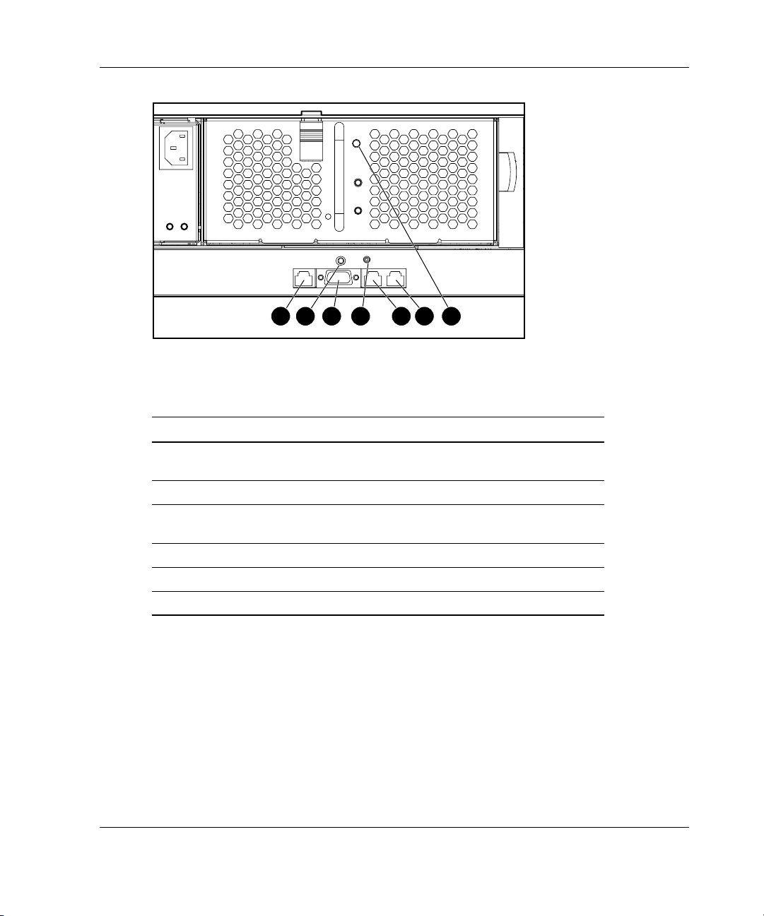
Figure 2-1: Rear panel Integrated Administrator
components
Table 2-1: Rear Panel Integrated Administrator Components
Item Description
1 Management (10/100 Ethernet) connector for remote access
through a Web-based user interface, Telnet, or Secure Shell
2 Integrated Administrator reset button
3 Console (serial) connector for local access to the command line
interface using a laptop computer
4 Integrated Administrator health LED
5 & 6 Enclosure link connectors (see previous Caution )
7 Enclosure Unit Identification button
HP ProLiant BL e-Class Integrated Administrator User Guide 2-3
Page 24

Getting Started
Determining the Integrated Administrator’s Initial IP Address
HP recommends that you connect a local client device, such as a laptop computer, to
the console (serial) connector in order to determine the initial IP address used by the
network to recognize the Integrated Administrator. After using that IP address to
access the Integrated Administrator locally using the console (serial) connector, you
can use the Integrated Administrator default values to complete the initial
configuration.
The organization of this section reflects this process:
•
Requirements for local client devices
•
Default values for the Integrated Administrator
•
Determining the IP address using the local console
Requirements for Local Client Devices
You can access the Integrated Administrator locally using the serial connector on the
rear panel of the enclosure using a local client device, such as a laptop computer.
The local client device must run a terminal emulator, such as HyperTerminal for
Windows systems or Kermit for Linux systems.
The terminal emulator must operate at the following settings:
•
Bits per second: 9600
•
Bits: 8
•
Parity: None
•
Stop bits: 1
•
Flow control: none
•
Emulation: VT100
•
Backspace key sends Ctrl-H
2-4 HP ProLiant BL e-Class Integrated Administrator User Guide
Page 25
Default Values for the Integrated Administrator
The Integrated Administrator is configured with a default user name, password, and
DNS name. A settings tag with the preconfigured values is attached to the
interconnect tray containing the Integrated Administrator module.
IMPORTANT: For security reasons, HP recommends changing the Administrator password
when accessing Integrated Administrator for the first time.
Determining the IP Address using the Local Console
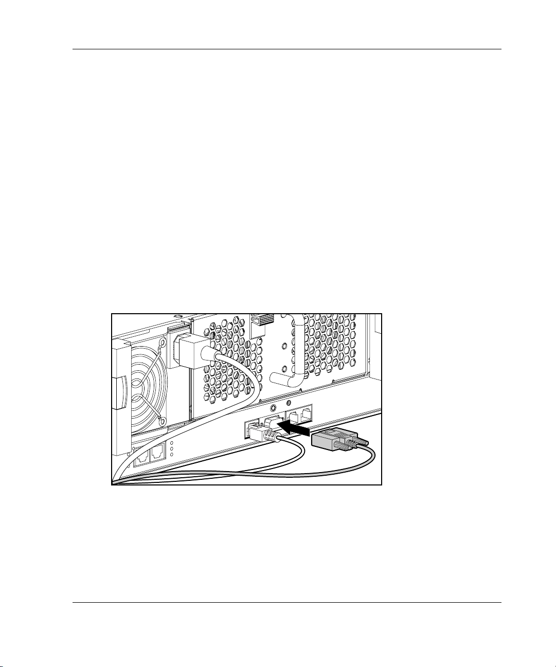
To determine the Integrated Administrator IP address using the local console:
1. Access the Integrated Administrator console:
a. Connect a local client device (such as a laptop computer) with VT100
terminal emulation software to the Integrated Administrator (serial) console
connector using the null-modem serial cable (provided with the enclosure).
Getting Started
Figure 2-2: Installing a local client device to the
Integrated Administrator (serial) console connector
HP ProLiant BL e-Class Integrated Administrator User Guide 2-5
Page 26

Getting Started
b. Open a terminal emulation session with the following settings: 9600 bps,
c. Log into the Integrated Administrator using the password on the settings tag
2. Establish the Integrated Administrator IP address.
For a detailed explanation of the command line conventions used in this
document, see Appendix A, “Command Line Conventions.”
— If a DHCP server is attached to the network, determine the Integrated
— If a DHCP server is not attached to the network, enter the following
8 data bits, no parity, and 1 stop bit.
attached to the interconnect tray.
Administrator IP address. Enter the following command at the command line
interface:
SHOW NETWORK
commands sequentially to assign a static IP address to the Integrated
Administrator:
SET IPCONFIG STATIC <IP address> <subnet mask>
SET GATEWAY <IP address>
SET DNS <primary address> {<secondary address>}
You can now access the Integrated Administrator using a web browser, Secure
Shell, Telnet, or SNMP.
2-6 HP ProLiant BL e-Class Integrated Administrator User Guide
Page 27
Setting Up the Web-Based User Interface
To set up the Web-based user interface:
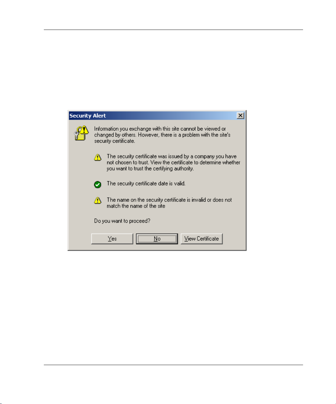
1. Enter the Integrated Administrator IP address or DNS name in the address bar of
the Web browser.
A security alert appears as an expected part of this procedure.
Getting Started
Figure 2-3: Certificate Security Alert
— If you click Yes, the browser continues to the Login window of Integrated
Administrator. The alert message appears each time you access the Integrated
Administrator management processor in a browser.
— If you click No, you are returned to what was previously displayed on your
browser.
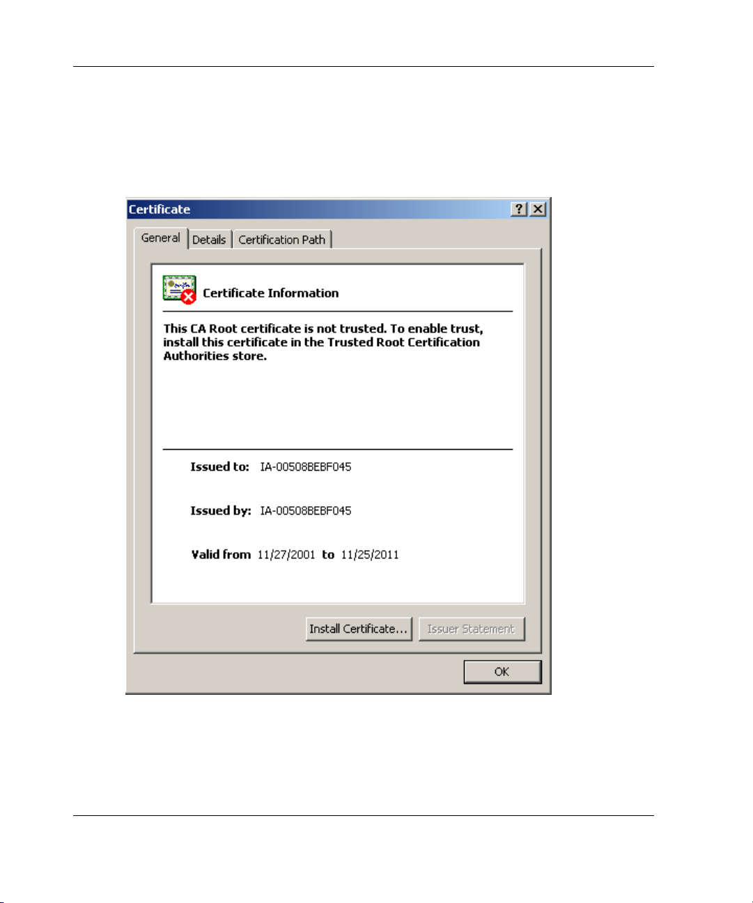
— If you click View Certificate, a popup window displays the certificate
information, as shown in Figure 2-4. Installing the certificate to your browser
prevents the security alert message from displaying in the future.
HP ProLiant BL e-Class Integrated Administrator User Guide 2-7
Page 28
Getting Started
NOTE: To install your own certificate onto the Integrated Administrator rather than the
automatically generated certificate, see the information on certificate-related commands in
Table 4-8 as well as the “Administering Security Certificates” section in Chapter 7,
“Performing Advanced Functions.”
Figure 2-4: Certificate Information window
IMPORTANT: If the certificate is removed from your browser, the security alert message
is displayed again.
2-8 HP ProLiant BL e-Class Integrated Administrator User Guide
Page 29
Getting Started
2. Install the certificate to your browser:
a. Click Install Certificate. The Certificate Manager Import Wizard starts.
b. Click Next.
c. Click Next for the browser to automatically select the certificate store when
the Certificate Store window appears.
d. Click Finish when the Completing the Certificate Manager Import
Manager Wizard window displays.
e. Click Yes to confirm the installation of the certificate when the confirmation
window displays.
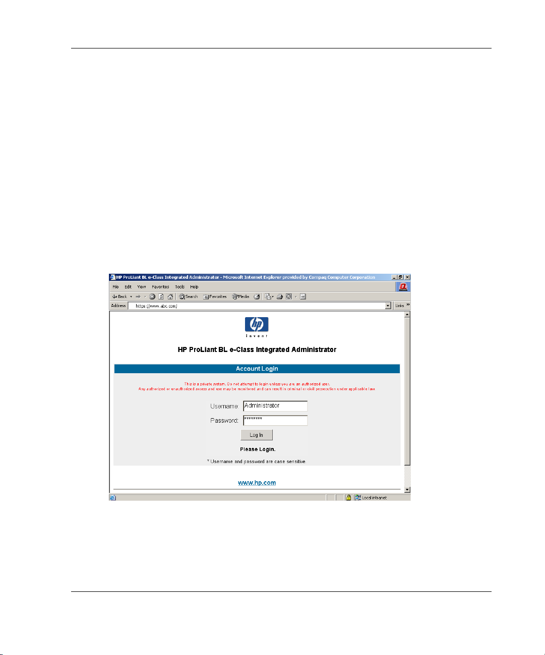
3. The screen prompts you for a user name and password. Use the default user name
and password from the settings tag attached to the interconnect tray and click
Log In.
Figure 2-5: Login screen
HP ProLiant BL e-Class Integrated Administrator User Guide 2-9
Page 30
Getting Started
After the default user name and password have been verified, the summary
window appears.
Figure 2-6: Integrated Administrator summary window
The Integrated Administrator summary window provides general information about
the Integrated Administrator, such as the user currently logged on, enclosure name
and status, and Integrated Administrator IP address and name.
2-10 HP ProLiant BL e-Class Integrated Administrator User Guide
Page 31

Additional Steps
HP recommends performing the following tasks:
•
Change the Administrator password
•
Set the date and time
Name the enclosure and rack
•
Set up groups, users, and access privileges
•
For detailed instructions on performing these tasks, see the appropriate sections
in Chapter 5, “Setting Up the System.”
Help
Additional assistance is available by means of the Integrated Administrator help
option. These links provide summary information about the features of Integrated
Administrator and helpful information for optimizing the operation of Integrated
Administrator.
Getting Started
HP ProLiant BL e-Class Integrated Administrator User Guide 2-11
Page 32

3
Web-Based User Interface
This chapter provides information for navigating the Integrated Administrator
Web-based user interface.
NOTE: Values appearing in the screens of this chapter are for illustrative purposes only.
HP ProLiant BL e-Class Integrated Administrator User Guide 3-1
Page 33

Web-Based User Interface
Accessing the Web-Based User Interface
IMPORTANT: Accessing the Web-based user interface is not supported from the console
(serial) connector.
To access the Integrated Administrator Web-based user interface with HTTP:
1. Get the DNS name from the settings tag attached to the interconnect tray.
2. Open a Web browser and enter the IP address or DNS name for the enclosure
you wish to access.
CAUTION: If your network does not provide DHCP and either Dynamic DNS or
WINS services, you need to configure a static IP address. See the “Accessing the
Command Line Interface Locally” section in Chapter 4, “Command Line Interface.”
Figure 3-1: Viewing the Login screen
3. Enter the user name and password at the Login prompt.
3-2 HP ProLiant BL e-Class Integrated Administrator User Guide
Page 34

Web-Based Navigation
The Web-based user interface displays information and receives input in the
following areas:
•
Top panel
•
Left panel
•
Deck panel
Top Panel
Figure 3-2 illustrates the location of the top panel.
Web-Based User Interface
Figure 3-2: Top panel of the Web-based user interface
HP ProLiant BL e-Class Integrated Administrator User Guide 3-3
Page 35

Web-Based User Interface
The top panel information is displayed at all times, including the following items:
•
Enclosure name
•
Current user
•
Tabs
The Integrated Administrator top panel provides real-time event notifications for an
enclosure according to two categories: caution and critical. When an event occurs,
the Integrated Administrator notifies the user by generating an icon that the user can
click to view more details:
Table 3-1: Event Notification Symbols
Icon Description
Caution
Critical
For a comprehensive list of events that trigger real-time notifications in a format that
reflects the Integrated Administrator representation, see Appendix D, “Event
Details.”
Two buttons appear on the top panel:
• • Printable View — Opens a separate window that shows information for cutting
and pasting purposes
Log Out — Logs you out of the Web-based user interface
3-4 HP ProLiant BL e-Class Integrated Administrator User Guide
Page 36

Left Panel
Figure 3-3 illustrates the location of the left panel.
Web-Based User Interface
Figure 3-3: Left panel of the Web-based user interface
The left panel displays which screens are available under each tab. Information
appearing in the left panel depends on which tab the user chooses from within the top
panel.
HP ProLiant BL e-Class Integrated Administrator User Guide 3-5
Page 37

Web-Based User Interface
Deck Panel
Figure 3-4 illustrates the location of the deck panel.
Figure 3-4: Deck panel of the Web-based user interface
The deck panel displays the areas of information provided by the available screens
under each tab. Information appearing in the deck panel depends on the option
chosen by the user from within the top panel and the left panel.
Enclosure Tab
The Enclosure tab provides access to the following screens:
•
Enclosure Information
•
Network Configuration
•
SNMP Configuration
3-6 HP ProLiant BL e-Class Integrated Administrator User Guide
Page 38

• Virtual Buttons
• System Log
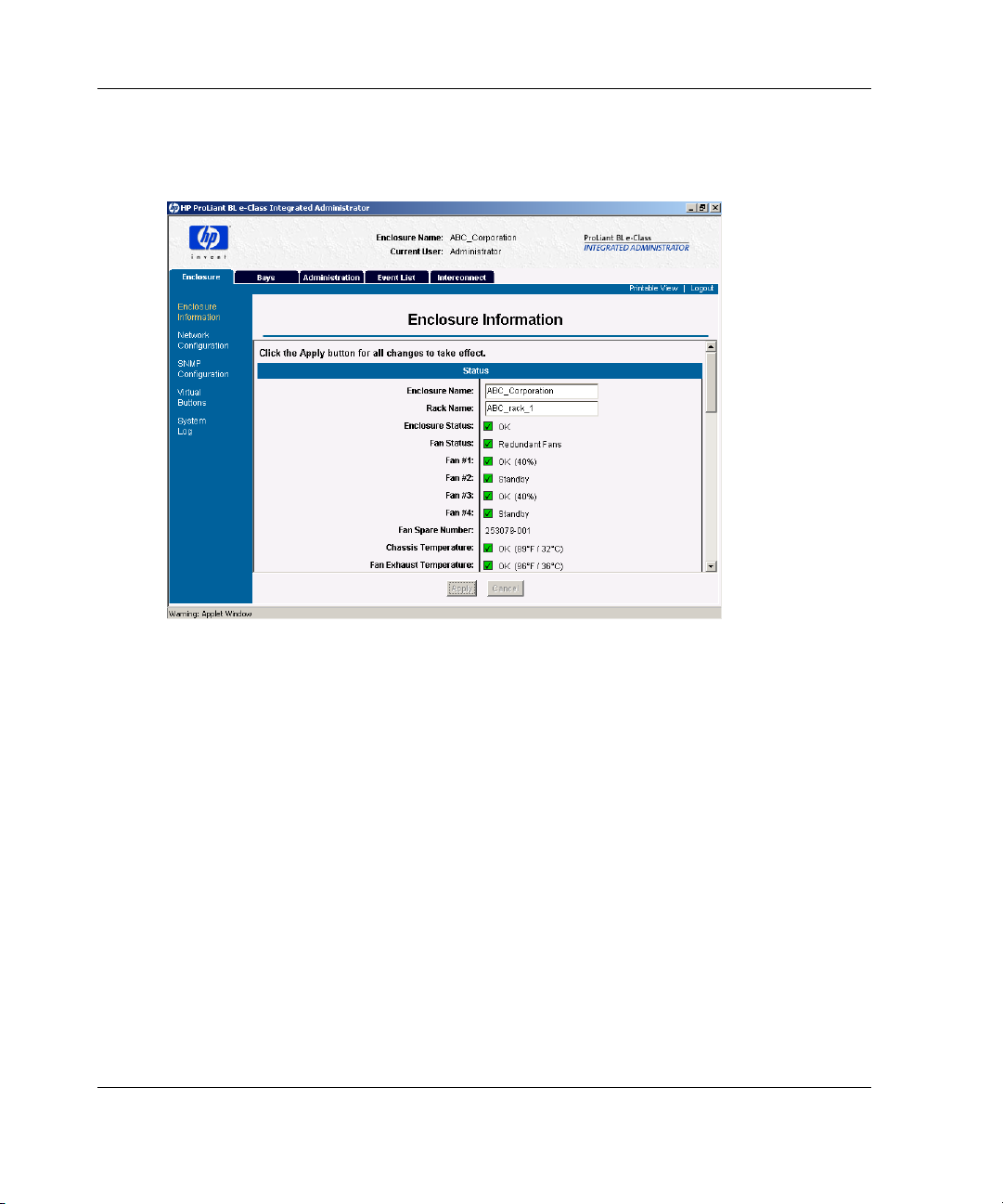
Enclosure Information
IMPORTANT: All users have read access to the information in this screen.
Figure 3-5 illustrates the information presented on the Enclosure Information
screen.
Web-Based User Interface
Figure 3-5: Enclosure Information screen (status area,
1 of 6, shown)
The Enclosure Information screen enables an enclosure administrator to update the
rack name, enclosure name, asset tag, time zone, date, and time, as well as observe
the status and general information for every component in the enclosure.
HP ProLiant BL e-Class Integrated Administrator User Guide 3-7
Page 39

Web-Based User Interface
Two buttons appear on the Enclosure Information screen:
• • Apply — Saves changes made to the screen
Cancel — Restores all fields on the screen to their original values
Table 3-2 describes the information displayed in the areas that comprise the
Enclosure Information screen.
Table 3-2: Enclosure Information Screen
Field Possible Values Description
Status Area
Enclosure Name Maximum 32 characters including
all alphanumeric, dash, and
underscore characters
Rack Name Maximum 32 characters including
all alphanumeric, dash, and
underscore characters
Enclosure Status OK, Degraded, or Failed Status of the enclosure
Fan Status Redundant or Non-redundant Redundant: all fans are functional.
Fan #1 – Fan #4 OK, Standby, Degraded, Failed, or
Testing
Percentage of full fan speed
Fan Spare Number The spare number for the fans
Name of the enclosure
Only enclosure administrators have
write access to this field.
For the default enclosure name, see
Appendix E, “Factory Default
Settings.”
Name of the rack
Only enclosure administrators have
write access to this field.
For the default rack name, see
Appendix E, “Factory Default
Settings.”
Non-redundant: at least one fan is not
functional.
Status of fans 1 through 4
installed in the enclosure
continued
3-8 HP ProLiant BL e-Class Integrated Administrator User Guide
Page 40

Web-Based User Interface
Table 3-2: Enclosure Information Screen continued
Field Possible Values Description
Temperature OK, Warm, Caution, or Critical Enclosure component temperature
sensor
Power Area
Power Subsystem
Status
Total Capacity Watts Total capacity of the power supplies
Power Supply #1
and #2 Status
AC Input #1 and #2
Status
Power Supply
Spare Number
General Area
Enclosure Type Enclosure product type
Option Part
Number
Serial Number Serial number for the enclosure
Asset Tag Maximum 31 characters including
Redundant or Non-redundant Redundant: both power supplies are
functional.
Non-redundant: one power supply is
missing or not functional.
OK, Degraded, or Failed Status of power supply #1 and power
supply #2
OK, Degraded, or Failed Status of AC input to power supply #1
and AC input to power supply #2
The spare number for the power
supplies installed in the enclosure
Part number for the enclosure
Asset tag
all alphanumeric, dash, and
underscore characters
Only enclosure administrators have
write access to this field.
For the default asset tag value, see
Appendix E, “Factory Default
Settings.”
continued
HP ProLiant BL e-Class Integrated Administrator User Guide 3-9
Page 41

Web-Based User Interface
Table 3-2: Enclosure Information Screen continued
Field Possible Values Description
General Area, continued
Interconnect Tray
Type
Interconnect Tray
Part Number
Interconnect Tray
Spare Number
Interconnect Tray
Serial Number
Integrated Administrator Area
Hardware Version Hardware version of the Integrated
Software Version Software version of the Integrated
Network Area
IP Address ###.###.###.###, where ###
DHCP Enabled or Disabled Shows the status of DHCP
Dynamic DNS Enabled or Disabled Shows the status of Dynamic DNS
MAC Address ##:##:##:##:##:##, where ##
ProLiant BL e-Class C-GbE
Interconnect Switch
ProLiant BL e-Class RJ-21
Interconnect
ProLiant BL e-Class RJ-45
Interconnect
Part number for the interconnect tray
Spare number for the interconnect
Serial number for the interconnect
ranges from 0 to 255
ranges from 00 to FF
Type of interconnect tray
tray
tray
Administrator of the enclosure
Administrator of the enclosure
The IP address of the Integrated
Administrator
This field only appears if DHCP is
enabled.
The MAC address of the Integrated
Administrator
continued
3-10 HP ProLiant BL e-Class Integrated Administrator User Guide
Page 42

Web-Based User Interface
Table 3-2: Enclosure Information Screen continued
Field Possible Values Description
Date and Time Area*
Time Zone Drop-down box with standard time
zones listed
Date mm/dd/yyyy The date assigned to the enclosure
Time hh:mm (24-hour time) The time assigned to the enclosure
* This section of the screen is not available on Linux browsers. If you are using a Linux system, use
the command line interface to change the date, time, and time zone.
Time zone assigned to the enclosure
For the default time zone, see
Appendix E, “Factory Default
Settings.”
For a list of all supported time zones,
see Appendix F, “Time Zone
Settings.”
For a detailed description of how to
set the time zone of the enclosure to
a value not listed in the drop-down
box, select option Other and see
Figure 3-6.
IMPORTANT: Only enclosure administrators have access to the Date and Time information. If
those fields are not being modified, the Integrated Administrator updates these fields every 20
seconds. If automatic time configuration is enabled, the date and time fields are grayed out
and cannot be modified.
HP ProLiant BL e-Class Integrated Administrator User Guide 3-11
Page 43

Web-Based User Interface
If you select Other for time zone, use the following window to set a user-defined
time zone:
Figure 3-6: User-defined time zone window
Three buttons appear on this window:
•
Apply — Applies the new time zone
•
Reset — Clears the time zone text box
•
Cancel — Cancels all changes and closes the window
For more information on accepted time zones, refer to Appendix F, “Time Zone
Settings”.
3-12 HP ProLiant BL e-Class Integrated Administrator User Guide
Page 44

Network Configuration
IMPORTANT: Only enclosure administrators have access to these settings.
Figure 3-7 illustrates the information presented on the Network Configuration
screen.
Web-Based User Interface
Figure 3-7: Network Configuration screen (information
and protocols areas, 1 and 2 of 3, shown)
The Network Configuration screen enables the enclosure administrator to modify
the network settings of an enclosure. These settings are specific to the enclosure and
do not affect the network configurations for server blades.
Two buttons appear at the bottom of this screen:
• • Apply — Saves changes made to the screen
Cancel — Restores all fields on the screen to their original values
HP ProLiant BL e-Class Integrated Administrator User Guide 3-13
Page 45

Web-Based User Interface
CAUTION: Both the Web and Secure Shell protocols must be enabled to allow
access to the Web-based user interface.
Table 3-3 describes the information displayed in the areas that comprise the Network
Configuration screen.
Table 3-3: Network Configuration Screen
Field Possible Values Description
Information Area
IP Address The IP address of the Integrated
Administrator
MAC Address The MAC address of the Integrated
Administrator
Protocols Area
Web
(HTTP/HTTPS)
SNMP Enabled or Disabled
Secure Shell Enabled or Disabled
Telnet Enabled or Disabled
Network Area
DHCP Gets the IP address of the Integrated
Static IP Sets a static IP address of the
Dynamic DNS Determines whether the Integrated
IP Address ###.###.###.###, where ###
3-14 HP ProLiant BL e-Class Integrated Administrator User Guide
Enabled or Disabled
ranges from 0 to 255
The default setting for each of the
protocol radio buttons is Enabled.
For more information on the default
settings of the system , see Appendix
E, “Factory Default Settings.”
Administrator from a DHCP server
Integrated Administrator
Administrator uses Dynamic DNS
Static IP address for the Integrated
Administrator (mandatory if Static IP
is selected)
continued
Page 46

Web-Based User Interface
Table 3-3: Network Configuration Screen continued
Field Possible Values Description
Network Area, continued
Subnet Mask ###.###.###.###, where ###
ranges from 0 to 255
Gateway Address ###.###.###.###, where ###
ranges from 0 to 255
DNS Server 1 ###.###.###.###, where ###
ranges from 0 to 255
DNS Server 2 ###.###.###.###, where ###
ranges from 0 to 255
Subnet mask for the Integrated
Administrator (mandatory if Static IP
is selected)
Gateway address for the Integrated
Administrator (optional field if Static IP
is selected)
The IP address for the primary DNS
server (optional field if Static IP is
selected)
The IP address for the secondary
DNS server (optional field if Static IP
is selected)
HP ProLiant BL e-Class Integrated Administrator User Guide 3-15
Page 47

Web-Based User Interface
SNMP Configuration
IMPORTANT: Only enclosure administrators have access to these settings.
Figure 3-8 illustrates the information presented on the SNMP Configuration screen.
Figure 3-8: SNMP Configuration screen
The SNMP Configuration screen enables an enclosure administrator to modify the
SNMP settings of an enclosure. These settings are specific to the enclosure and do
not affect the network configurations for server blades.
Two buttons appear at the bottom of this screen:
• • Apply — Saves changes made to the screen
Cancel — Restores all fields on the screen to their original values
3-16 HP ProLiant BL e-Class Integrated Administrator User Guide
Page 48

Web-Based User Interface
Table 3-4 describes the information presented on the SNMP Configuration screen:
Table 3-4: SNMP Configuration Screen
Field Possible Values Description
System Information Area
SNMP Status Enabled or Disabled Displays if SNMP is enabled or
disabled
System Name The name of the enclosure
System Location Up to 20 characters including all
alphanumeric, dash, underscore,
and space characters
System Contact Up to 20 characters including all
alphanumeric, dash, underscore,
and space characters
Community Strings And Trap Destinations Area
The SNMP location of the enclosure
For the default SNMP location, see
Appendix E, “Factory Default
Settings.”
The SNMP contact of the enclosure
For the default SNMP contact, see
Appendix E, “Factory Default
Settings.”
Read Community 1-20 characters including all
alphanumeric, dash, and
underscore characters
HP ProLiant BL e-Class Integrated Administrator User Guide 3-17
Displays the SNMP read community
string
If this is left blank, “public” is
assigned.
For the default Read community
string, see Appendix E, “Factory
Default Settings.”
continued
Page 49

Web-Based User Interface
Table 3-4: SNMP Configuration Screen continued
Field Possible Values Description
Community Strings And Trap Destinations Area, continued
Write Community Up to 20 characters including all
alphanumeric, dash, and
underscore characters
Add Adds an IP address to the list of trap
Remove Removes the selected IP addresses
Sets the SNMP write community
string
If this is left blank, SNMP SET
commands are disabled.
For the default Read community
string, see Appendix E, “Factory
Default Settings.”
destinations
from the list of trap destinations
3-18 HP ProLiant BL e-Class Integrated Administrator User Guide
Page 50

Virtual Buttons
IMPORTANT: Only enclosure administrators can execute these commands.
Figure 3-9 illustrates the information presented on the Virtual Buttons screen.
Web-Based User Interface
Figure 3-9: Virtual Buttons screen (Enclosure tab)
The Virtual Buttons screen enables an enclosure administrator to modify the power
state of the enclosure and Unit Identification LED from a remote location in order to
facilitate troubleshooting by technicians in the data center.
The Toggle On/Toggle Off button remotely changes the state of the enclosure Unit
Identification LED.
Figure 3-10 describes the information presented in the Enclosure Power area of the
Virtual Buttons screen:
HP ProLiant BL e-Class Integrated Administrator User Guide 3-19
Page 51

Web-Based User Interface
Figure 3-10: Virtual Buttons screen (Enclosure Power
area)
You can select the appropriate function with the following buttons:
• • Restart Integrated Administrator restarts the Integrated Administrator and
does not affect the server blades.
IMPORTANT: Click Restart Integrated Administrator only at the direction of HP
support personnel. You must click Apply for these settings to take effect.
Power Off Enclosure attempts a graceful shutdown of the system for 5 minutes,
after which time this command powers down all components of the enclosure
immediately.
IMPORTANT: Whenever possible, HP recommends that you use the operating system
shutdown procedures before powering down a server blade or enclosure. After the
enclosure is powered off, powering on can only occur by local access to the system.
3-20 HP ProLiant BL e-Class Integrated Administrator User Guide
Page 52

System Log
The System Log screen provides an enclosure administrator with a chronological list
of events and fixes associated with the enclosure.
Two buttons appear at the bottom of this screen:
• • Refresh — Refreshes the screen
Clear — Clears the system log
Figure 3-11 describes the information presented in the System Log screen:
Web-Based User Interface
Figure 3-11: System Log screen
HP ProLiant BL e-Class Integrated Administrator User Guide 3-21
Page 53

Web-Based User Interface
Bays Tab
The Bays tab provides access to the following screens:
•
Bay List
•
Bay Information
•
Remote Console
•
Virtual Buttons
•
Console Log
Bay List
The Bay List screen enables an enclosure administrator to observe and update the
assignment of groups to server blade bays, as well as monitor the status of each
server blade installed in the enclosure.
Group administrators and group members with permissions can view the server blade
bays assigned to their groups.
3-22 HP ProLiant BL e-Class Integrated Administrator User Guide
Page 54

Web-Based User Interface
Figure 3-12 and Table 3-5 describe the information presented in the Bay List screen:
Figure 3-12: Bay List screen
HP ProLiant BL e-Class Integrated Administrator User Guide 3-23
Page 55

Web-Based User Interface
Table 3-5: Bay List Field Descriptions
Field Possible Values Description
Bay # 1-20 Server blade bay number
UID Field Displays a blue circle if the unit identification
(UID) LED of the blade is lit
Server Blade
Name
Assigned to Group Name of the group that owns that bay
Status OK, Degraded, or Failed The status and power state of the server blade
Name of the server blade in that server blade
bay as defined by the operating system of the
server blade
Note: Without the server blade health driver
properly installed, the Integrated Administrator
cannot obtain the server blade name.
Please note the following permissions related to the action buttons of the Bay List
screen (Table 3-6).
Table 3-6: Bay List Action Buttons and Permissions
Button Function Permissions
View/Modify Opens the Blade
Information screen
Remote Console Opens the Remote
Console screen
Virtual Buttons Opens the Virtual
Buttons screen
Console Log Opens the Console Log
screen
View Group Opens the View/Modify
Group screen
Bay Assignment Opens the Bay
Assignment dialog box
(see Figure 3-12)
3-24 HP ProLiant BL e-Class Integrated Administrator User Guide
Enclosure administrators, group administrators,
and group members with permissions
Enclosure administrators and group
administrators with permissions
Enclosure administrators and group
administrators with permissions
Enclosure administrators, group administrators,
and group members with permissions
Enclosure administrators only
Enclosure administrators only
Page 56

Web-Based User Interface
Figure 3-13: Bay Assignment dialog box
The Action radio buttons (Assign/Unassign) determine what action to take when you
click OK.
IMPORTANT: If you wish to reassign a server blade from one group to another, you must first
unassign the server blade; otherwise the command does not execute.
The Assign to Group drop-down box contains all groups within the enclosure to
determine the group with ownership of the server blade bay.
HP ProLiant BL e-Class Integrated Administrator User Guide 3-25
Page 57

Web-Based User Interface
Bay Information
IMPORTANT: Be sure the Integrated Administrator displays up-to-date server blade
information by rebooting the server blade after installing the server blade health driver.
Figure 3-14 illustrates the information presented on the Bay Information screen.
Figure 3-14: Bay Information screen (bay 5 shown)
The Bay Information screen enables an enclosure administrator to observe the status
and general information for a server blade in a given server blade bay. Group
administrators and group members with View rights to the server blade bay can also
observe this information.
IMPORTANT: To be sure that the Bay Information screen displays the optimal number of
possible values, you must have the server blade health driver installed.
Table 3-7 describes the information presented on the Bay Information screen for all
enclosure administrators and for group members and group with rights to the server
blade bay.
3-26 HP ProLiant BL e-Class Integrated Administrator User Guide
Page 58

Web-Based User Interface
Table 3-7: Bay Information Screen
Field Possible Values Description
Status Area
Bay Number Bay number
Server Blade Name Name of the server blade as specified
with the server blade operating system
Status OK, Degraded, or Failed Status of the server blade
Thermal Condition OK, Warm, Caution, or Critical Thermal condition of the blade
Enclosure Name Name of enclosure
For the default enclosure name, see
Appendix E, “Factory Default
Settings.”
Rack Name Name of the rack
For the default rack name, see
Appendix E, “Factory Default
Settings.”
General Area
Server Blade Type Product name of the server blade
Server Blade
Installed OS
Spare Number Spare number of the server blade
Serial Number Serial number of the server blade
Asset Tag Asset tag number of the server blade
BIOS version mm/dd/yyyy ROM version on the server blade
CPU # Type Type of processor on the server blade
CPU # Max. Speed Speed associated with the server
Installed RAM Amount of memory installed on the
HP ProLiant BL e-Class Integrated Administrator User Guide 3-27
Operating system installed on the
server blade
blade processor
server blade
continued
Page 59

Web-Based User Interface
Table 3-7: Bay Information Screen continued
Field Possible Values Description
NIC #1 and #2 MAC
Addresses
Remote Console
IMPORTANT: If a server blade is running the Microsoft Windows® 2000 operating system,
only sequences that occur before the loading of the operating system are visible using Remote
Console, unless the server blade is running the HP ProLiant Serial Console for Windows 2000
Server service.
To allow Remote Console access to a server blade, install the HP ProLiant Serial Console for
Windows 2000 Server service, located at
www.compaq.com/support/files/server
Enclosure administrators and group administrators with access to the bay can click
Remote Console to open a remote text-based console to the server blade in the bay.
##:##:##:##:##:##, where ##
ranges from 00 to FF.
MAC address of the NIC 1 interface
and NIC 2 interface of the server blade
3-28 HP ProLiant BL e-Class Integrated Administrator User Guide
Page 60

Web-Based User Interface
Figure 3-15 illustrates the information presented on the Remote Console screen.
Figure 3-15: Remote Console screen (bay 5 shown)
For information on establishing remote console connectivity, see the “Enabling
Remote Console Sessions to Server Blades” section in Chapter 5, “Setting Up the
System.”
HP ProLiant BL e-Class Integrated Administrator User Guide 3-29
Page 61

Web-Based User Interface
Virtual Buttons
Figure 3-16 illustrates the information in the Virtual Buttons screen.
Figure 3-16: Virtual Buttons screen (bay 5 shown)
Enclosure administrators and group administrators with permissions can use the
Virtual Buttons screen to modify the state of the power state and Unit Identification
LED of a server blade in order to facilitate troubleshooting from a remote location.
The Virtual Buttons screen enables group administrators and enclosure
administrators to reboot, power off, or identify the server blade with the following
items:
• The Toggle On/Off button remotely changes the state of the server blade Unit
Identification LED.
3-30 HP ProLiant BL e-Class Integrated Administrator User Guide
Page 62

• You can select the appropriate function in the Server Blade Power area using the
following radio buttons:
— Reboot reboots the server blade.
— Power Off attempts a graceful shutdown of the server blade for 5 minutes,
after which time this command powers down the server blade immediately.
— Power Off Immediately powers off the server blade forcefully.
CAUTION: Without the server blade health driver or an ACPI-compliant
operating system, the Integrated Administrator cannot gracefully shut down a
server blade. This condition can result in the permanent loss of critical data.
IMPORTANT: You must click Apply for these settings to take effect.
IMPORTANT: Whenever possible, HP recommends that you use the operating system
shutdown procedures before powering down a server blade or enclosure. Once the
enclosure is powered off, powering on can only occur with local access to the system.
Console Log
IMPORTANT: Only group members, group administrators, and enclosure administrators can
view a console log of a server blade.
Web-Based User Interface
The Console Log screen displays the console log for the specified bay. The console
log of the bay is not stored between reboots of the Integrated Administrator, so the
information will only include what has taken place since the last power on of the
Integrated Administrator.
The data captured in the console log is all output from the serial console of the server
blade that occurred while no one was connected to the console. For security reasons,
console output during a user connection session is not logged.
The Refresh button refreshes the console log for the current server blade.
HP ProLiant BL e-Class Integrated Administrator User Guide 3-31
Page 63

Web-Based User Interface
Administration Tab
IMPORTANT: For an explanation of user rights associated with the Integrated Administrator,
see the “User Permissions” section in Chapter 5, “Setting Up the System.”
Under the Administration tab, you can access the following screens:
•
User List
•
Group List
•
Add User
•
Add Group
•
View/Modify User
•
View/Modify Group
3-32 HP ProLiant BL e-Class Integrated Administrator User Guide
Page 64

User List
Figure 3-17 illustrates the information presented in the User List screen.
Web-Based User Interface
Figure 3-17: User List screen
The User List screen enables an appropriate group administrator or enclosure
administrator to observe and update user access to groups and server blade bays.
HP ProLiant BL e-Class Integrated Administrator User Guide 3-33
Page 65

Web-Based User Interface
Please note the following permissions related to the action buttons of the User List
screen (Table 3-8).
Table 3-8: User List Action Buttons and Permissions
Button Function Permissions
View/Modify User Opens the View/Modify
User screen
Remove User
Removes the selected
user (unless the account
is your own)
Enclosure administrators can access and
modify the information for any user.
Users can access and modify the information for
their own account.
Only enclosure administrators can execute this
command.
Table 3-9 describes the information presented in the User List screen.
Table 3-9: User List Screen
Field Possible Values Description
User Name User’s login name
See Appendix E, “Factory Default
Settings,” for factory default user
accounts.
Full Name User’s full name
Account Type Administrator or User Shows if the user is an enclosure
administrator
Account Status Enabled or Disabled Shows if the user’s account is
enabled
Group Membership Shows the groups in which the user
has membership
3-34 HP ProLiant BL e-Class Integrated Administrator User Guide
Page 66

Group List
Figure 3-18 and Table 3-10 describe the information presented in the Group List
screen.
Web-Based User Interface
Figure 3-18: Group List screen
The Group List screen enables an enclosure administrator to observe and update the
assignment of groups and users to server blade bays.
HP ProLiant BL e-Class Integrated Administrator User Guide 3-35
Page 67

Web-Based User Interface
Two buttons appear on this screen:
• • View/Modify Group—Opens the View/Modify Group screen
Remove Group—Removes the selected group
IMPORTANT: Enclosure administrators can view and modify the information for all groups.
Group administrators and group members can view the information for the groups in which
they are members.
Table 3-10: Group List Screen
Field Description
Group Name Group name
Assigned Bays Server blade bays that the
Group Members Users with membership in the
Add User
IMPORTANT: Only enclosure administrators have access to this area of the Integrated
Administrator.
group owns
group
3-36 HP ProLiant BL e-Class Integrated Administrator User Guide
Page 68

Web-Based User Interface
Figure 3-19 and Table 3-11 describe the information presented in the User Account
area of the Add User screen:
Figure 3-19: Add User screen (User Account area,
1 of 2, shown)
The Add User screen enables an enclosure administrator to create a user profile,
including group and server blade bays assignments.
Two buttons appear on this screen:
• • Apply—Saves changes made to this screen
Cancel—Restores all fields on this screen to their original values
HP ProLiant BL e-Class Integrated Administrator User Guide 3-37
Page 69

Web-Based User Interface
Table 3-11: Add User Screen
Field Possible Values Description
User Account Area
User Name 1-13 characters including
alphanumeric, dash, and
underscore characters
The user name must begin with a
letter. A maximum of 25 users can
be created in addition to the
reserved accounts.
Password 3-8 characters including all
printable characters
Confirm Password 3-8 characters including all
printable characters
Account Type Radio buttons (Administrator and
User)
Account Status Radio buttons (Enabled and
Disabled)
Full Name (optional) 0-20 characters
Accepts only alphanumeric, dash,
underscore, and space characters
Contact Information
(optional)
0-20 characters
Accepts only alphanumeric, dash,
underscore, and space characters.
Login name of the user.
Note: “Administrator, “switcha,”
“switchb,“ and “all” are reserved
names and cannot be used. This
restriction is not case-sensitive.
User’s password
User’s password
Determines if the user has
enclosure administrator rights
Determines if the user’s account is
enabled
Full name of the user
Optional user contact information
continued
3-38 HP ProLiant BL e-Class Integrated Administrator User Guide
Page 70

Web-Based User Interface
Table 3-11: Add User Screen continued
Field Possible Values Description
Group Membership Area
Group Names All groups are listed. A list of all possible groups
Group Membership X number of groups (all groups in
which the user has membership)
Add User [View] >>> Adds the user to the selected
Add User
[View/Modify] >>>
<<< Remove User Removes the user from the
Adds the user to the selected
A list of all users that are members
of the group
groups in the Group Names text
box with View rights for group
members
These groups appear in the Group
Membership textbox. The user
loses View/Modify rights for group
administrators if they previously
had them.
groups in the Group Names text
box to the group with View/Modify
rights for group administrators or
View rights for group members
selected groups in the Group
Membership text box
Add Group
IMPORTANT: Only enclosure administrators have access to this area of the Integrated
Administrator.
HP ProLiant BL e-Class Integrated Administrator User Guide 3-39
Page 71

Web-Based User Interface
Figure 3-20 illustrates the information presented in the Add Group screen.
Figure 3-20: Add Group screen (Group Information and
Bay Assignment areas, 1 and 2 of 3, shown)
IMPORTANT: Grayed-out checkboxes are unavailable because they are already assigned to
another group.
The Add Group screen enables an enclosure administrator to create a group profile,
including user and server blade bays assignments.
Two buttons appear on this screen:
• • Apply—Saves changes made to this screen
Cancel—Restores all fields on this screen to their original values
3-40 HP ProLiant BL e-Class Integrated Administrator User Guide
Page 72

Web-Based User Interface
Table 3-12: Add Group Screen
Field Possible Values Description
Group Information Area
Group Name 1-13 characters including
alphanumeric, dash, and
underscore characters
The group name must begin with a
letter. A maximum of 20 groups
can be created.
Group
Description
(optional)
Bay Assignment Area
Bay 1–Bay 20 Determines which bays the group owns
Select All Selects all checkboxes of the bays
Clear All Clears all checkboxes of the bays
Group Membership Area
User Names All users and enclosure
Group Members X number of users (all users that
0-20 characters
Accepts only alphanumeric, dash,
underscore, and space characters
administrators are listed.
are members of the group)
Name of group
Description of group
Only one group can own a particular
bay. If a checkbox is disabled, another
group already owns the bay.
A list of all possible users
A list of all users that are members of
the group
continued
HP ProLiant BL e-Class Integrated Administrator User Guide 3-41
Page 73

Web-Based User Interface
Table 3-12: Add Group Screen continued
Field Possible Values Description
Group Membership Area, continued
Add User [View] >>> Adds selected users in the User Names
text box to the group with View rights for
group members
Users lose View/Modify rights for group
administrators if they previously had
them.
Add User [View/Modify] >>> Adds selected users in the User Names
text box to the group with View/Modify
rights for group administrators
<<< Remove User Removes selected users in the Group
Members text box from the group
View/Modify User
You can access the View/Modify User screen by clicking any row in the User List
and then clicking View/Modify User.
The View/Modify User screen provides the same functions and has the same access
as the Add User screen. See the “Add User” section in this chapter.
View/Modify Group
You can access the View/Modify Group screen by clicking any row in the Group
List and then clicking View/Modify Group.
The View/Modify Group screen the provides same functions and has the same
access as the Add Group screen. See the “Add Group” section in this chapter.
3-42 HP ProLiant BL e-Class Integrated Administrator User Guide
Page 74

Event List Tab
IMPORTANT: The Event List differs from the System Log in the following ways:
• Any user can view the Event List. Only enclosure administrators can access the
System Log.
• The messages in the Event List are limited to cautions and critical failures. Refer to the
enclosure System Log for information on both failures and fixes.
• The Event List only displays messages received since the user logged into the Integrated
Administrator. The System Log displays every message generated by the enclosure
diagnostics.
The Integrated Administrator provides real-time event notifications for an enclosure
according to two categories of severity (caution and critical) described in Table 3-13.
Table 3-13: Event Notification Icons
Icon Description
Caution—An event that does not prevent the enclosure from
operating, maintaining power, or serving its user community
When a caution event occurs, a reasonable guarantee that
operability can persist no longer exists.
Web-Based User Interface
Critical—An event that prevents the continued operation of the
enclosure
When a critical event occurs, the inoperability of the enclosure is
imminent .
Two buttons appear on this screen:
• • View Event Details—Navigates to the appropriate screen within the Integrated
Administrator to view more details
Clear All Events—Clears all events from event list
HP ProLiant BL e-Class Integrated Administrator User Guide 3-43
Page 75

Web-Based User Interface
Figure 3-21 illustrates the information presented in the Event List screen.
Figure 3-21: Event List screen (fan failure shown)
The Event List provides the following information for each event:
•
Severity
•
Source
•
Date
•
Time
•
Event Details
For detailed information regarding the Event List, including a comprehensive list of
event messages, see Appendix D, “Event Details.”
3-44 HP ProLiant BL e-Class Integrated Administrator User Guide
Page 76

Interconnect Tab
Figure 3-22 illustrates the information presented in the Interconnect Tray screen:
Web-Based User Interface
Figure 3-22: Interconnect Tray screen
The Interconnect Tray screen allows anyone to view information about the
interconnect tray. It allows enclosure administrators to connect to the remote console
of one of the interconnect switches if installed.
Table 3-14 describes the information displayed in the areas that comprise the
Interconnect Tray screen.
Table 3-14: Interconnect Tray screen
Field Possible Values Description
Interconnect Tray Information Area
Status OK, Degraded, or
Failed
HP ProLiant BL e-Class Integrated Administrator User Guide 3-45
Status of the
interconnect tray
continued
Page 77

Web-Based User Interface
Table 3-14: Interconnect Tray screen continued
Field Possible Values Description
Temperature OK, Warm, Caution,
or Critical
Switch A Status OK, Degraded, or
Failed
Switch B Status OK, Degraded, or
Failed
Manufacturer Manufacturer of the
Product Name Product name of the
Interconnect Tray Part
Number
Interconnect Tray
Spare Number
Interconnect Tray
Serial Number
Switch Terminal Console Area (only present if an interconnect switch
is installed)
Switch A button Opens a new window
Switch B button Opens a window to the
Part number for the
Spare number for the
Serial number for the
Thermal status of the
interconnect tray
Status of Switch A. This
will only be displayed if
an interconnect switch
is installed.
Status of Switch B. This
will only be displayed if
an interconnect switch
is installed.
interconnect tray
interconnect tray
interconnect tray
interconnect tray
interconnect tray
to the remote console
of Switch A
remote console of
Switch B
3-46 HP ProLiant BL e-Class Integrated Administrator User Guide
Page 78

4
Command Line Interface
This chapter provides reference material for operating the Integrated Administrator
CLI. This chapter provides command line-related information in the following
format:
•
Accessing the Command Line Interface
•
Operating the command line interface
— General commands
— General management commands
— User account commands
— Enclosure network configuration commands
— Enclosure management commands
— Server bay management commands
•
Functionality exclusive to the command line interface
For a detailed explanation of the command line conventions used in this document,
see Appendix A, “Command Line Conventions.”
For easy reference, the index of this book also provides a comprehensive listing of
the commands supported by the Integrated Administrator.
HP ProLiant BL e-Class Integrated Administrator User Guide 4-1
Page 79

Command Line Interface
Accessing the Command Line Interface
You can access the CLI remotely through the management (10/100 Ethernet)
connector or locally through the console (serial) connector on the rear panel of the
enclosure.
Accessing Remotely through the Management Connector
To access the Integrated Administrator command line interface remotely through the
management (10/100 Ethernet) connector:
1. Get the default host name from the settings tag attached to the interconnect tray.
2. Open a Telnet or Secure Shell application and enter the IP address or DNS name
for the enclosure you wish to access.
CAUTION: Using Telnet instead of Secure Shell means your remote session,
including password, appears in clear text on that network.
3. Enter the user name and password into the Login prompt.
Accessing Locally through the Console Connector
To access the Integrated Administrator locally through the serial connector:
1. Connect a local client device, such as a laptop computer, to the serial connector
using the null-modem cable that ships with the enclosure.
IMPORTANT: Client devices must satisfy the requirements provided in the “Requirements
for Local Client Devices” section in this chapter.
2. Open the terminal emulator and press the Enter key to get the login prompt.
3. Enter the user name and password.
4-2 HP ProLiant BL e-Class Integrated Administrator User Guide
Page 80

Operating the Command Line Interface
General Commands
Table 4-1: General Commands
Command Description Restrictions
Command Line Interface
CLEAR
SCREEN
EXIT
HELP
{
<command> |
TREE
}
LOGOUT
QUIT
SLEEP
<seconds>
Clears the terminal screen None
Exits the command line interpreter None
If a command is given, the usage and
help text for the command are
shown. If TREE is given, all
commands are shown in a tree
format. If no argument is given, all
base commands are displayed.
Exits the command line interpreter None
Exits the command line interpreter None
Pauses the sessions for a fixed
period of time. Useful for adding
delays to scripts. The <seconds>
field can be any whole number from 1
– 86400. Once the pause has
started, no way exists to continue the
session before time runs out; but you
can terminate the session and start
another one.
None
None
HP ProLiant BL e-Class Integrated Administrator User Guide 4-3
Page 81

Command Line Interface
General Management Commands
Table 4-2: General Management Commands
Command Description Restrictions
CLEAR SESSION
SWITCH [A |
B]
CLEAR SSHKEY
CONNECT
SWITCH [A |
B]
DOWNLOAD
CERTIFICATE
<url>
DOWNLOAD
SSHKEY
Terminates a Terminal session from the
enclosure.
This is not a graceful termination. The
connected user loses any unsaved work.
Removes the contents of the Secure Shell
authorized keys file. After performing this
command, you will not be able to login using
public key-based authentication.
Opens a remote console connection to switch A
or B.
A single switch cannot support multiple
simultaneous remote console sessions.
Downloads a CA supplied PKCS#7 file to
replace the current security certificate on the
system.
Supported protocols are http, ftp, and tftp. The
URL should be formatted as follows:
protocol://host/path/file
If your ftp server does not support anonymous
connections, you can specify a username and
password by augmenting the host part in the
above format with username:password@host.
Downloands an authorized key file to use with
Secure Shell v2 which can contain the public
keys for any enclosure administrator. Supported
protocols are http, ftp, and tftp. The url should
be formatted as protocol://host/path/file. If your
ftp server does not support anonymous
connections, you can specify a username and
password by replacing the host part in the
previous format with username:password@host.
Group administrators
may only execute this
command for server
blade bays to which
they have access.
Only enclosure
administrators may
execute this command.
Only enclosure
administrators may
execute this command.
Only enclosure
administrators may
execute this command.
Only enclosure
administrators may
execute this command.
continued
4-4 HP ProLiant BL e-Class Integrated Administrator User Guide
Page 82

Command Line Interface
Table 4-2: General Management Commands continued
Command Description Restrictions
GENERATE
CERTIFICATE
REQUEST
GENERATE
CERTIFICATE
SELFSIGNED
PING
{<number>}
[<IP address>
| <server
name>]
SET DISPLAY
EVENTS [ON |
OFF]
SET EXPERT
{MODE} [ON |
OFF]
SET FACTORY
SET SCRIPT
MODE [ON |
OFF]
Generates a PKCS#10 certificate request. Only enclosure
administrators may
execute this command.
Generates a self-signed certificate. Only enclosure
administrators may
execute this command.
Sends ICMP echo messages to a remote IP
device.
If <number> is omitted, only 5 packets are sent.
Packets are sent out at 1-second intervals.
Turns event notification on or off
The Integrated Administrator preserves this
setting across all logins.
Turns EXPERT MODE on or off. When EXPERT
MODE is turned on, the system will not prompt
the user to confirm actions. Users should
exercise caution when working in EXPERT
MODE as many actions are not reversible.
Sets the Integrated Administrator back to its
factory defaults.
The “Administrator” account password does not
change. The Integrated Administrator is
restarted after all the changes are made.
Note: This command removes all groups, users,
and other customization from the memory of the
enclosure, and the information is unrecoverable.
When SCRIPT MODE is on, all prompting and
verifications of entries ceases.
If SCRIPT MODE is on, the following commands
require a password argument: ADD USER, SET
USER PASSWORD, or SET PASSWORD.
Default values are used for any parameters that
would normally require user interaction.
The <IP address> must
be in the form
###.###.###.### where
### ranges from
0 to 255.
None
None
Only the “Administrator”
account may execute
this account.
None
continued
HP ProLiant BL e-Class Integrated Administrator User Guide 4-5
Page 83

Command Line Interface
Table 4-2: General Management Commands continued
Command Description Restrictions
SHOW EXPERT
{MODE}
:
SHOW SESSIONS
SHOW
SSHFINGERPRIN
T
SHOW SSHKEY
Displays the current EXPERT MODE setting for
the current user.
Displays the connection to each bay and switch
if one exists.
Only one user may connect to each bay and
switch at a time. It also shows each user that is
currently logged in, the user’s port number,
connect time, and remote system name.
Displays the key fingerprint of the host SSH
public key of the Integrated Administrator. This
can be used from the serial console to validate
the identity of the Integrated Administrator
before initializing an SSH connection across a
network.
Displays the contents of the existing Secure
Shell authorized keys file that is being used for
enclosure administrator key-based
authentication.
None
Users may not run this
command. Group
members and group
administrators may only
see the sessions for
bays assigned to groups
to which they belong.
Enclosure
administrators see all
sessions.
None
Only enclosure
administrators may
execute this command.
4-6 HP ProLiant BL e-Class Integrated Administrator User Guide
Page 84

User Account Commands
Table 4-3: User Account Commands
Command Description Restrictions
Command Line Interface
ADD GROUP
<group name>
ADD USER
<user name>
{<password>}
Adds a group to the
system
The default group
description is blank.
Adds a user to the
system
If a password is not
given, the user is
prompted for one. If
SCRIPT MODE is
enabled, the password
is not optional and
must be provided.
Only enclosure administrators may execute this
command.
A maximum of 20 groups may be added to the
system.
The <group name> must be unique to all other
group names and user names and is casesensitive. It must be 1-13 characters long and can
include all alphanumeric, the dash, and the
underscore characters. It must begin with a letter.
Note: Administrator, “switcha,” “switchb,” and “all”
are reserved names and cannot be used. This
restriction is not case-sensitive.
See Appendix E, “Factory Default Settings,” for
factory default group accounts.
Only enclosure administrators may execute this
command.
A maximum of 25 users may be added in addition
to the reserved accounts.
The <user name> must be unique to all other user
names and group names and is case-sensitive. It
must be 1-13 characters long and can include all
alphanumeric, the dash, and the underscore
characters. The user name must begin with a
letter. The <password> must be 3-8 characters
long and includes all printable characters. If a
password is not entered, the user is prompted for
one.
Note: Administrator, “switcha,” “switchb,” and “all”
are reserved names and cannot be used. This
restriction is not case-sensitive.
See Appendix E, “Factory Default Settings,” for
factory default user accounts.
continued
HP ProLiant BL e-Class Integrated Administrator User Guide 4-7
Page 85

Command Line Interface
Table 4-3: User Account Commands continued
Command Description Restrictions
ASSIGN
ADMINISTRATO
R {RIGHTS}
<user name>
ASSIGN BAY
[ALL | <bay
number> {[ ,
| -] <bay
number>}]
<group name>
ASSIGN USER
<user name>
<group name>
{[VIEW |
MODIFY]}
DISABLE USER
<user name>
ENABLE USER
<user name>
REMOVE GROUP
[ALL |
<group
name>]
Promotes a user to have
enclosure administrator
permissions
Group membership is not
deleted in case enclosure
administrator rights are
removed at a later time.
Assigns one or more bays to
a group
If a bay is already assigned to
a group, it must first be
unassigned before executing
this command.
Assigns a user to a group with
View rights (for group
members) or View/Modify
rights (for group
administrators)
If View or View/Modify is not
specified, View is chosen by
default.
Disables a user account
The user is immediately
logged out of the system and
prevented from log in until the
account is enabled.
Enables a user account that
was previously disabled by
the DISABLE USER
command
Removes a group and
automatically unassigns all
bays within the group
Only enclosure administrators may execute
this command.
The <user name> is case-sensitive.
Only enclosure administrators may execute
this command.
The <group name> is case-sensitive.
Only enclosure administrators may execute
this command.
The <user name> and <group name> are
case-sensitive. The “Administrator” account
cannot be added to a group.
Only enclosure administrators may execute
this command.
The <user name> is case-sensitive. The
“Administrator” account cannot be disabled.
Only enclosure administrators may execute
this command.
The <user name> is case-sensitive.
Only enclosure administrators may execute
this command.
The <group name> is case-sensitive.
continued
4-8 HP ProLiant BL e-Class Integrated Administrator User Guide
Page 86

Table 4-3: User Account Commands continued
Command Description Restrictions
Command Line Interface
REMOVE USER
[ALL | <user
name>]
SET GROUP
{DESCRIPTION
} <group
name>
<description
>
SET PASSWORD
{<password>}
Removes a user from the
system
If ALL is specified, the
command is run for all users
except the default system
accounts.
Sets a group’s description. Only enclosure administrators may execute
Sets the password of the user
currently logged into the
Integrated Administrator.
If a password is not given on
the command line, the user is
prompted for one.
Note: This command is not
valid in SCRIPT MODE if
password is not specified.
Only enclosure administrators may execute
this command.
The <user name> is case-sensitive. The
“Administrator,” “switcha,” and “switchb”
accounts cannot be removed.
this command.
The <group name> is case-sensitive. The
<description> must be 0-20 characters long
and can include all alphanumeric
characters, the dash, the underscore, and
spaces.
The default group description is blank.
If spaces are part of the contact
information, enclose the information in
quotes.
The <password> must be 3-8 characters
long and can include all printable
characters.
continued
HP ProLiant BL e-Class Integrated Administrator User Guide 4-9
Page 87

Command Line Interface
Table 4-3: User Account Commands continued
Command Description Restrictions
SET USER
CONTACT
{<user
name>}
<contact
info>
SET USER
FULLNAME
{<user
name>} <full
name>
SET USER
PASSWORD
<user name>
{<new
password>}
If no <user name> exists, the
command modifies the
contact info of the user that
executed the command.
Sets a user’s full name.
If no <user name> exists, the
command modifies the full
name of the user that is
currently logged in.
Sets a user’s password.
If you do not supply a
password on the command
line, you are prompted for
one.
Note: This command is not
valid in SCRIPT MODE if
password is not specified.
Only enclosure administrators may modify
another user’s contact information.
The <user name> is case-sensitive. The
<contact info> must be 0-20 characters
long and can include all alphanumeric
characters, the dash, the underscore, and
spaces.
The default contact information is blank.
If spaces are part of the contact
information, enclose the information in
quotes.
Only enclosure administrators may modify
another user’s full name.
The <user name> is case-sensitive. The
<full name> must be 0-20 characters long
and can include all alphanumeric, the dash,
the underscore, and space characters.
The default full name is blank.
If spaces are part of this information,
enclose the information in quotes.
Only enclosure administrators may modify
another user’s password. Only the
“Administrator” account may modify the
password of the “Administrator” account.
The <user name> is case-sensitive. The
<new password> must be 3-8 characters
long and can include all printable
characters.
continued
4-10 HP ProLiant BL e-Class Integrated Administrator User Guide
Page 88

Table 4-3: User Account Commands continued
Command Description Restrictions
Command Line Interface
SHOW GROUP
[<group
name> | ALL]
SHOW USER
[<user name>
| ALL]
UNASSIGN
ADMINISTRATO
R {RIGHTS}
<user name>
UNASSIGN
USER <user
name> <group
name>
Displays the group’s
description, a list of members
with View permission, a list of
members with View/Modify
permission, number of bays,
and a list of each of the bays
the group manages.
If ALL is entered, the
command is run for every
group, and displays the group
description and the number of
assigned users and bays.
Displays the user’s full name,
contact, whether the user has
administrator rights, whether
the account is enabled, and
the groups for which the user
has View or View/Modify
permissions.
If ALL is entered, this
information is given for every
user and an asterisk before
the user name denotes the
current user.
Takes enclosure administrator
rights from a user.
Removes the user from the
specified group.
Group members and group administrators
only see the groups in which they have
membership. Users may not execute this
command.
The <group name> is case-sensitive.
If spaces are part of this information,
enclose the information in quotes.
Only enclosure administrators may view
another user’s information.
The <user name> is case-sensitive. Users
who do not have enclosure administrator
permissions only see their user information.
Only enclosure administrators may execute
this command. The “Administrator” account
cannot have enclosure administrator rights
taken away.
The <user name> is case-sensitive.
Only enclosure administrators may execute
this command.
The <user name> and <group name> are
case-sensitive.
HP ProLiant BL e-Class Integrated Administrator User Guide 4-11
Page 89

Command Line Interface
Enclosure Network Configuration Commands
Table 4-4: Enclosure Network Configuration Commands
Command Description Restrictions
ADD SNMP
TRAPRECEIVE
R <IP
address>
DISABLE
SECURESH
DISABLE
SNMP
DISABLE
TELNET
DISABLE WEB
Adds an IP address to receive SNMP
traps.
Only v1 traps are supported. Traps are
directed to the SNMP default port, 162.
Disables Secure Shell access to the
Integrated Administrator.
Disabling Secure Shell prevents
access to the Web-based user
interface and the Secure Shell terminal
interface until a terminal session reenables the Secure Shell protocol.
Disables SNMP support for the
Integrated Administrator.
Does not clear the SNMP trap
receivers that have been configured.
SNMP trap receivers can still be added
and removed. If SNMP is disabled,
Insight Manager agents do not work
properly.
Disables Telnet access to the
Integrated Administrator.
Disables HTTP and HTTPS access to
the Integrated Administrator.
This command prevents access to the
Web-based user interface.
Only enclosure administrators may
execute this command.
A maximum of 8 IP address may be
added to receive SNMP traps.
The <IP address> must be in the
form ###.###.###.### where ###
ranges from 0 to 255.
Only enclosure administrators may
execute this command.
Only enclosure administrators may
execute this command.
Only enclosure administrators may
execute this command.
Only enclosure administrators may
execute this command.
continued
4-12 HP ProLiant BL e-Class Integrated Administrator User Guide
Page 90

Command Line Interface
Table 4-4: Enclosure Network Configuration Commands continued
Command Description Restrictions
DOWNLOAD
CONFIG
<url>
ENABLE
SECURESH
ENABLE SNMP
ENABLE
TELNET
ENABLE WEB
REMOVE SNMP
TRAPRECEIVE
R <IP
address>
SET DNS
<primary
address>
{<secondary
address>}
Downloads a previously saved
configuration file from a specific IP host
The files are auto-executed in script
mode. The file is not allowed to change
the password of the “Administrator”
account. Supported protocols are http,
ftp, and tftp. The URL should be
formatted as protocol://host/path/file. If
your ftp server does not support
anonymous connections, you can
specify a username and password by
replacing the host part in the previous
format with username:password@host.
Enables Secure Shell support for the
Integrated Administrator
Enables SNMP support for the
Integrated Administrator
Enables Telnet access to the
Integrated Administrator
Enables HTTP and HTTPS access to
the Integrated Administrator
Removes an IP address from the list of
systems to receive SNMP traps
Sets the primary and secondary DNS
server addresses
These servers are only used if the
system is currently configured to use a
static IP address.
Only enclosure administrators may
execute this command.
The IP address must be in the form
###.###.###.### where ### ranges
from 0 to 255.
Only enclosure administrators may
execute this command.
Only enclosure administrators may
execute this command.
Only enclosure administrators may
execute this command.
Only enclosure administrators may
execute this command.
Only enclosure administrators may
execute this command.
The IP address must be in the form
###.###.###.### where ### ranges
from 0 to 255.
Only enclosure administrators may
execute this command.
The <primary address> and
<secondary address> must be in
the form ###.###.###.### where
### ranges from 0 to 255.
continued
HP ProLiant BL e-Class Integrated Administrator User Guide 4-13
Page 91

Command Line Interface
Table 4-4: Enclosure Network Configuration Commands continued
Command Description Restrictions
SET GATEWAY
<IP
address>
SET
IPCONFIG
[DHCP
{DYNAMICDNS
} | STATIC
<IP
address>
<netmask>]
SET SNMP
COMMUNITY
[READ |
WRITE]
<community
name>
SET SNMP
CONTACT
<contact>
Sets the network default gateway
This gateway is only used if the system
is configured to use a static IP
address.
Sets up the Integrated Administrator IP
configuration
The gateway and DNS addresses are
cleared. The optional DYNAMICDNS
argument enables Dynamic DNS.
Sets the community name for the read
or write SNMP community
The default names for the read and
write community are “public” and blank,
respectively. If a blank write community
name is given, SNMP set commands
are disabled until a non-empty
community name is given.
Configures the name of the system
contact
The default contact is blank.
Only enclosure administrators may
execute this command.
The <IP address> needs to be in
the form ###.###.###.### where
each ### ranges from 0 to 255.
Only enclosure administrators may
execute this command.
The <IP address> and <netmask>
need to be in the form
###.###.###.### where each ###
ranges from 0 to 255.
Only enclosure administrators may
execute this command.
The write <community name> must
be 0-20 characters long, and the
read <community name> must be
1-20 characters long. Both include
all alphanumeric, the underscore,
and the dash characters.
The default read community name
is “public.” The default
write community name is blank.
Only enclosure administrators may
execute this command.
The <contact> must be 0-20
characters long and includes all
alphanumeric characters, the
underscore, the dash, and the
space.
If spaces are part of this
information, enclose the information
in quotes.
continued
4-14 HP ProLiant BL e-Class Integrated Administrator User Guide
Page 92

Command Line Interface
Table 4-4: Enclosure Network Configuration Commands continued
Command Description Restrictions
SET SNMP
LOCATION
<location>
SHOW
NETWORK
SHOW SNMP
Configures the SNMP location of the
enclosure.
The default location is blank.
Displays the DHCP state, Dynamic
DNS state, IP address, subnet mask,
gateway address, primary and
secondary DNS addresses, MAC
address, HTTP and HTTPS server
status, SNMP status, Secure Shell
status, and Telnet status of the
enclosure.
Displays the SNMP system name,
location, and contact; read community
name; write community name; and a
list of the trap destinations.
Only enclosure administrators may
execute this command.
The <location> must be 0-20
characters long and includes all
alphanumeric characters, the
underscore, the dash, and the
space.
If spaces are part of this
information, enclose the information
in quotes.
None
Only enclosure administrators may
execute this command.
HP ProLiant BL e-Class Integrated Administrator User Guide 4-15
Page 93

Command Line Interface
Enclosure Management Commands
Table 4-5: Enclosure Management Commands
Command Description Restrictions
CLEAR SYSLOG
ENCLOSURE
POWEROFF
ENCLOSURE
{FORCE}
RESTART
SET DATE
MMDDhhmm
{{CC}YY} {TZ}
Clears the enclosure system log Only enclosure administrators
may execute this command.
Once deleted, this information
cannot be restored.
Performs a graceful shutdown of the
enclosure. Each blade is first gracefully
shutdown. If the FORCE argument is
given, the enclosure and all blades are
immediately shutdown.
Restarts the Integrated Administrator.
This does not affect current operation
of bays in the system.
Sets the date of the enclosure with the
following definitions:
• MM: month
• DD: day
• hh: hour (24-hour time)
• mm: minute
• CC: century
• YY: year
• TZ: time zone (case-sensitive)
If the time zone is left blank, the
current time zone is left in effect.
Only enclosure administrators
may execute this command.
Only enclosure administrators
may execute this command.
Only enclosure administrators
may execute this command.
• MM is an integer from 1-12.
• DD is an integer from 1-31.
• hh is an integer from 0-23.
• mm is an integer from 0-59.
For a list of time zones, see
Appendix F, “Time Zone
Settings.”
NTP must be disabled before
manually setting the date and
time.
continued
4-16 HP ProLiant BL e-Class Integrated Administrator User Guide
Page 94

Command Line Interface
Table 4-5: Enclosure Management Commands continued
Command Description Restrictions
SET ENCLOSURE
ASSET {TAG}
<asset tag>
SET ENCLOSURE
NAME
<enclosure
name>
SET ENCLOSURE
UID [ON |
OFF]
SET RACK NAME
<rack name>
SHOW CONFIG
Changes the enclosure asset tag Only enclosure administrators
may execute this command.
The <asset tag> must be 1-31
characters long and includes
alphanumeric, dash, and
underscore characters.
The default enclosure asset tag
is blank. To set a blank asset tag,
specify the blank value using
quotes.
Changes the enclosure name Only enclosure administrators
may execute this command.
The <enclosure name> must be
1-32 characters long and
includes all alphanumeric, the
dash, and the underscore
characters.
The default enclosure name is
IA-MAC where MAC is replaced
with the actual MAC address.
Turns the enclosure Unit Identification
LED on or off
Sets the name for the rack where the
enclosure resides
Displays the script required to recreate
the settings of the enclosure
Passwords are not included for any
user.
Only enclosure administrators
may execute this command.
Only enclosure administrators
may execute this command.
The <rack name> must be 1-32
characters long and includes all
alphanumeric, dash, and
underscore characters.
The default rack name is
“UnnamedRack.”
Only enclosure administrators
may execute this command.
continued
HP ProLiant BL e-Class Integrated Administrator User Guide 4-17
Page 95

Command Line Interface
Table 4-5: Enclosure Management Commands continued
Command Description Restrictions
SHOW DATE
SHOW DISPLAY
EVENT
SHOW
ENCLOSURE FAN
[<fan number>
| ALL]
SHOW
ENCLOSURE
INFO
SHOW
ENCLOSURE
POWERSUPPLY
[<power
supply
number> |
ALL]
SHOW
ENCLOSURE
STATUS
Displays the current date, time, and
time zone of the internal clock of the
enclosure.
Displays whether event notification is
on or off.
Displays the status, redundancy,
partner, speed, and part number for
the requested fan.
If ALL is entered, this information is
shown for all fans.
Displays the enclosure name, type,
part number, serial number, and asset
tag; the Integrated Administrator
software and hardware version;
Integrated Administrator MAC address;
and the interconnect tray type, part
number, and serial number.
Displays the power supply status, AC
input status, capacity, input voltage
range #1 (measured in Volts), input
voltage range #2 (if necessary,
measured in Volts), input frequency
range (measured in Hertz), part
number, serial number, and hardware
revision for the specified power supply
if one is specified or for all power
supplies if ALL is given.
Under an enclosure status heading,
this command displays the health,
Integrated Administrator health, and
unit identification LED of the enclosure.
Under a power status heading, this
command displays the power status
and capacity.
None
None
None
None
None
None
continued
4-18 HP ProLiant BL e-Class Integrated Administrator User Guide
Page 96

Command Line Interface
Table 4-5: Enclosure Management Commands continued
Command Description Restrictions
SHOW
ENCLOSURE
TEMP
SHOW RACK
NAME <rack
name>
SHOW SYSLOG
ENCLOSURE
SHOW TRAY
INFO
UPDATE IMAGE
<url>
Displays the locale, status (OK, warm,
degraded, or failed), temperature in
degrees Fahrenheit, and temperature
in degrees Celsius for all temperature
sensors.
Shows the name for the rack where the
enclosure resides.
The default rack name is
“UnnamedRack.”
Displays the syslog of the enclosure
with 22 lines per screen.
Typing “q” quits the command; any
other key shows the next screen if
more information exists to display.
Typing “c” continuously displays the
System Log without page breaks.
Displays the manufacturer, product
name, part number, serial number, and
spare number of the interconnect tray.
Downloads a new image from a server
over the network and uses the image
to upgrade the firmware of the
enclosure.
None
None
Only enclosure administrators
may execute this command.
None
Only enclosure administrators
may execute this command.
<URL> can be any of the
following:
• http://host/path
• tftp://host/path
• ftp://username:password
@host/path
• ftp://host/path
where host is a fully qualified
domain name or an IP
address and path is the
pathname of the flash image
to download.
continued
HP ProLiant BL e-Class Integrated Administrator User Guide 4-19
Page 97

Command Line Interface
Table 4-5: Enclosure Management Commands continued
Command Description Restrictions
UPLOAD CONFIG
<url>
Uploads the current runtime
configuration to the specified FTP or
TFTP server.
Only enclosure administrators
may execute this command.
Server Bay Management Commands
Table 4-6: Server Bay Management Commands
Command Description Restrictions
CLEAR BAY BOOT
[FIRST | ONCE] [ALL
| <bay number> {[ ,
| - ] <bay number>}
CLEAR SESSION BAY
<bay number>
CONNECT BAY <bay
number>
Clears the setting for the IPL to
be passed to the blade at the
next reboot. The “FIRST”
]
argument resets the IPL for all
subsequent reboots. The
“ONCE” argument resets the
IPL for the next reboot only.
This command is only valid for
present blades.
This command requires BIOS
version 06/15/02 or greater for
the ProLiant BL10e server
blade ROM.
Terminates a Terminal session
from the enclosure.
This is not a graceful
termination. The connected
user loses any unsaved work.
Opens a remote console
session to the server blade
with that server blade bay
number.
A server blade can only
support one remote console
session at a time.
Only enclosure and group
administrators may execute
this command.
Enclosure administrators may
execute this command for
server blade bays and the
interconnect switch.
Only enclosure and group
administrators may execute
this command.
continued
4-20 HP ProLiant BL e-Class Integrated Administrator User Guide
Page 98

Command Line Interface
Table 4-6: Server Bay Management Commands continued
Command Description Restrictions
GENERATE NMI <bay
number>
POWEROFF BAY <bay
number> {[ , | - ]
<bay number>}
{FORCE}
POWERON BAY <bay
number> {[ , | - ]
<bay number>} {[PXE
| HDD | RBSU]}
Generates an NMI on the
specified blade.
The consequences of an NMI
are operating system specific.
Performs a graceful shutdown
of the server blade in the
specified bay.
If the FORCE argument is
given, the server blade is
immediately shut down. This
means the server blade could
lose data or become unstable.
If no server blade is in the
specified bay, the user is told
that the bay is empty.
Powers on the specified server
blade.
If no server blade is in the
specified bay, the user is told
that the bay is empty.
The optional boot arguments
require a BIOS version of
06/15/02 or greater of the
ProLiant BL10e Server blade
ROM.
Adding an optional boot
argument forces the blade to
abandon the regular boot order
and forces a boot using the
specified method.
Only enclosure and group
administrators may execute
this command.
Only enclosure and group
administrators may execute
this command.
Only enclosure and group
administrators may execute
this command.
continued
HP ProLiant BL e-Class Integrated Administrator User Guide 4-21
Page 99

Command Line Interface
Table 4-6: Server Bay Management Commands continued
Command Description Restrictions
REBOOT BAY <bay
number> {[ , | - ]
<bay number>}
{FORCE} {[PXE | HDD
| RBSU]}
SET BAY BOOT FIRST
[HDD | PXE] <bay
number> {[ , | - ]
<bay number>}
SET BAY BOOT ONCE
[HDD | PXE | RBSU]
<bay number> {[ , |
- ] <bay number>}
Sends a request to the server
blade to perform a graceful
shutdown.
The server blade is then
powered on. If no server blade
is in the specified bay, the user
is told that the bay is empty.
The optional boot arguments
require a BIOS version of
06/15/02 or greater of the
ProLiant BL10e Server blade
ROM.
Adding an optional boot
argument forces the blade to
abandon the regular boot order
and forces a boot using the
specified method.
Sets the IPL for each
subsequent reboot. This
setting is only valid for present
blades and is cleared if a blade
is removed.
This command requires BIOS
version 06/15/02 or greater for
the ProLiant BL10e server
blade ROM.
Sets the boot device to be
used on the next boot of the
bay(s) specified. This setting is
only valid on present blades
and is cleared if the blade is
removed.
This command requires BIOS
version 06/15/02 or greater for
the ProLiant BL10e server
blade ROM.
Only enclosure and group
administrators may execute
this command.
Only enclosures and
administrators may execute
this command.
Only enclosure and
administrators may execute
this command.
continued
4-22 HP ProLiant BL e-Class Integrated Administrator User Guide
Page 100

Command Line Interface
Table 4-6: Server Bay Management Commands continued
Command Description Restrictions
SET BAY UID <bay
number> {[ , | - ]
<bay number>} [ON |
OFF]
SHOW BAY INFO [ALL |
<bay number> {[ , |
- ] <bay number>}]
SHOW BAY LIST [ALL |
<group name>]
SHOW BAY STATUS [ALL
| <bay number> {[ ,
| - ] <bay number>}]
Turns a Unit Identification LED
on the server blade on or off.
Displays the following fields:
Assigned to group, type, name,
installed operating system, part
number, serial number, asset
tag, BIOS version, all CPU
types and associated
maximum speeds, memory,
NIC #1 MAC, and NIC #2
MAC.
If no server is in the bay, the
user is shown the assigned to
group and the server blade
type.
Displays the assigned to
group, remote console user,
and server blade name for
each bay in a particular group
if a group name is specified or
all bays if ALL is specified
Displays the power (On or Off),
assigned to group, remote
console user, health (OK, CPU
failure, or power module
failure), thermal (OK, warm,
degraded, or failed), and Unit
Identification LED (On or Off)
for the server blade.
Only enclosure and group
administrators may execute
this command.
Group members and group
administrators only see
information for the bays in their
groups.
Group members and group
administrators only see
information for the bays in their
groups.
Group members and group
administrators only see
information for the bays in their
groups.
continued
HP ProLiant BL e-Class Integrated Administrator User Guide 4-23
 Loading...