

Hp PROLIANT BL35P, PROLIANT BL45P, PROLIANT BL40P, PROLIANT BL30P, PROLIANT BL25P RDMA protocol: improving network performance
Page 1

RDMA protocol: improving network performance
technology brief
Abstract.............................................................................................................................................. 2
Introduction......................................................................................................................................... 2
Limitations of TCP/IP ............................................................................................................................ 2
RDMA solution .................................................................................................................................... 3
RDMA over TCP .................................................................................................................................. 4
RDMA protocol overview .................................................................................................................. 5
RDMA data transfer operations.......................................................................................................... 6
Send operations........................................................................................................................... 6
RDMA write................................................................................................................................. 7
RDMA read ................................................................................................................................. 7
Terminate .................................................................................................................................... 7
Verbs.............................................................................................................................................. 7
RNIC interface................................................................................................................................. 8
RDMA over InfiniBand.......................................................................................................................... 9
InfiniBand RDMA protocols ............................................................................................................. 10
Direct Access Programming Library .............................................................................................. 10
Sockets Direct Protocol ................................................................................................................ 10
SCSI RDMA Protocol................................................................................................................... 11
InfiniBand link operation ................................................................................................................. 11
Conclusion........................................................................................................................................ 11
For more information.......................................................................................................................... 12
Call to action .................................................................................................................................... 12
Page 2

Abstract
Remote Direct Memory Access (RDMA) is a data exchange technology that improves network
performance by streamlining data processing operations. This technology brief describes how RDMA
can be applied to the two most common network interconnects, Ethernet and InfiniBand, to provide
efficient throughput in the data center.
Introduction
Advances in computing and storage technologies are placing a considerable burden on the data
center’s network infrastructure. As network speeds increase and greater amounts of data are moved,
it takes more processing power to process data communication.
A typical data center today uses a variety of disparate interconnects for servers-to-servers and serverto-storage links. The use of multiple system and peripheral bus interconnects decreases compatibility,
interoperability, and management efficiency and drives up the cost of equipment, software, training,
and the personnel needed to operate and maintain them. To increase efficiency and lower costs, data
center network infrastructure must be transformed into a unified, flexible, high-speed fabric.
Unified high-speed infrastructures require a high-bandwidth, low-latency fabric that can move data
efficiently and securely between servers, storage, and applications. Evolving fabric interconnects and
associated technologies provide more efficient and scalable computing and data transport within the
data center by reducing the overhead burden on processors and memory. More efficient
communication protocols and technologies, some of which run over existing infrastructures, free
processors for more useful work and improve infrastructure utilization. In addition, the ability of fabric
interconnects to converge functions in the data center over fewer, or possibly even one, industrystandard interconnect presents significant benefits.
Remote direct memory access (RDMA) is a data exchange technology that promises to accomplish
these goals and make iWARP (a protocol that specifies RDMA over TCP/IP) a reality. Applying RDMA
to switched-fabric infrastructures such as InfiniBand™ (IB) can enhance the performance of clustered
systems handling large data transfers.
Limitations of TCP/IP
Transmission Control Protocol and Internet Protocol (TCP/IP) represent the suite of protocols that drive
the Internet. Every computer connected to the Internet uses these protocols to send and receive
information. Information is transmitted in fixed data formats (packets), so that heterogeneous systems
can communicate. The TCP/IP stack of protocols was developed to be an internetworking language
for all types of computers to transfer data across different physical media. The TCP and IP protocol
suite includes over 70,000 software instructions that provide the necessary reliability mechanisms,
error detection and correction, sequencing, recovery, and other communications features.
Computers implement the TCP/IP protocol stack to process outgoing and incoming data packets.
Today, TCP/IP stacks are usually implemented in operating system software and packets are handled
by the main (host) processor. As a result, protocol processing of incoming and outgoing network
traffic consumes processor cycles—cycles that could otherwise be used for business and other
productivity applications. The processing work and associated time delays may also reduce the ability
of applications to scale across multiple servers. As network speeds move beyond 1 gigabit per
second (Gb/s) and larger amounts of data are transmitted, processors become burdened by TCP/IP
protocol processing and data movement.
The burden of protocol stack processing is compounded by a finite amount of memory bus
bandwidth. Incoming network data consumes the memory bus bandwidth because each data packet
2
Page 3
must be transferred in and out of memory several times (Figure 1): received data is written to the
y
(
device driver buffer, copied into an operating system (OS) buffer, and then copied into application
memory space.
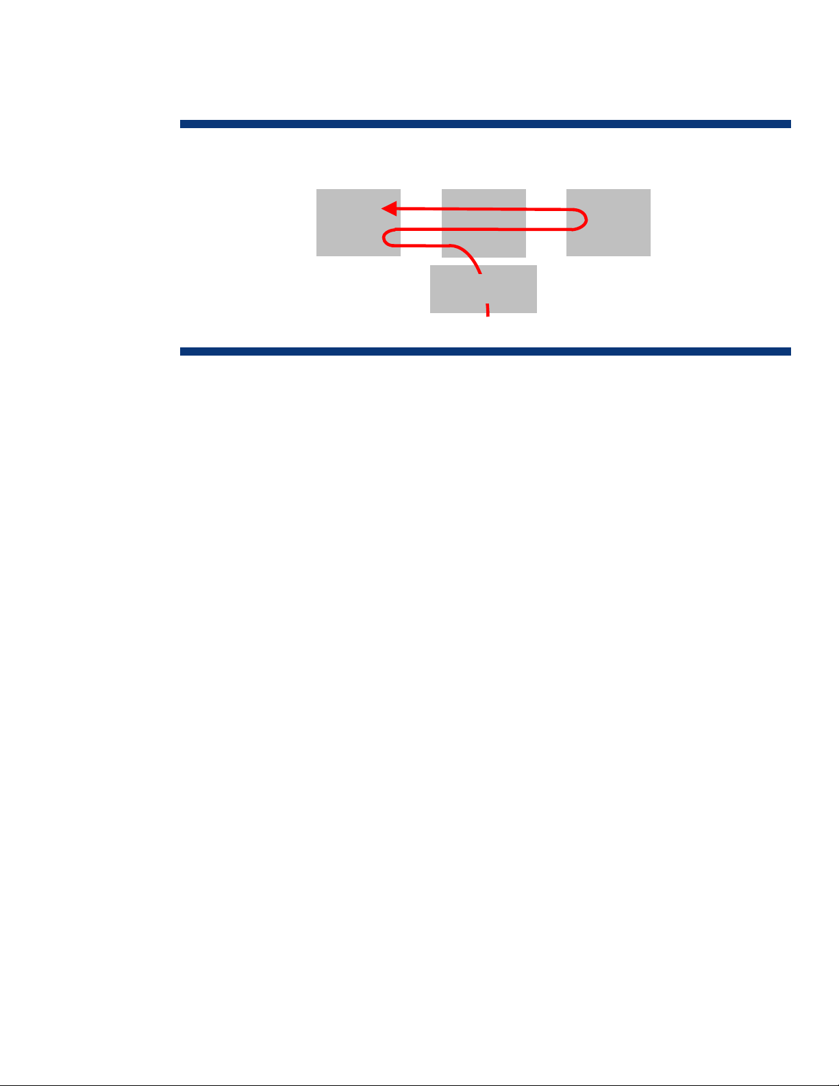
Figure 1. Typical flow of network data in receiving host
Memor
NOTE: The actual number of
memory copies varies depending on
Example: Linux uses 2).
OS
Chipset
Network I/F
CPU
These copy operations add latency, consume memory bus bandwidth, and require host processor
(CPU) intervention. In fact, the TCP/IP protocol overhead associated with 1 Gb of Ethernet traffic can
increase system processor utilization by 20 to 30 percent. Consequently, software overhead for
10 Gb Ethernet operation has the potential to overwhelm system processors. An InfiniBand network
using TCP operations to satisfy compatibility issues will suffer from the same processing overhead
problems that Ethernet networks have.
RDMA solution
Inherent processor overhead and constrained memory bandwidth are performance obstacles for
networks that use TCP, whether out of necessity (Ethernet) or compatibility (InfiniBand).
For Ethernet, the use of a TCP/IP offload engine (TOE) and RDMA can diminish these obstacles. A
network interface adapter (NIC) with a TOE assumes TCP/IP processing duties, freeing the host
processor for other tasks. The capability of a TOE is defined by its hardware design, the OS
programming interface, and the application being run.
RDMA technology was developed to move data from the memory of one computer directly into the
memory of another computer with minimal involvement from their processors. The RDMA protocol
includes information that allows a system to place transferred data directly into its final memory
destination without additional or interim data copies. This “zero copy” or “direct data placement”
(DDP) capability provides the most efficient network communication possible between systems.
Since the intent of both a TOE and RDMA is to relieve host processors of network overhead, they are
sometimes confused with each other. However, the TOE is primarily a hardware solution that
specifically takes responsibility of TCP/IP operations, while RDMA is a protocol solution that operates
at the upper layers of the network communication stack. Consequently, TOEs and RDMA can work
together: a TOE can provide localized connectivity with a device while RDMA enhances the data
throughput with a more efficient protocol.
For InfiniBand, RDMA operations provide an even greater performance benefit since InfiniBand
architecture was designed with RDMA as a core capability (no TOE needed).
RDMA provides a faster path for applications to transmit messages between network devices and is
applicable to both Ethernet and InfiniBand. Both these interconnects can support all new and existing
network standards such as Sockets Direct Protocol (SDP), iSCSI Extensions for RDMA (iSER), Network
File System (NFS), Direct Access File System (DAFS), and Message Passing Interface (MPI).
3
Page 4
RDMA over TCP
Ethernet is the most prevalent network interconnect in use today. IT organizations have invested
heavily in Ethernet technology and most are unwilling to tear out their networks and replace them.
Reliance on Ethernet is justified by its low cost, backward compatibility, and consistent bandwidth
upgrades over time. Today’s Ethernet networks, which use TCP/IP operations, commonly operate at
100 megabits per second (Mb/s) and 1 gigabit per second (Gb/s). Next-generation speeds will
increase to 10 Gb/s. Customer migration to 10-Gb Ethernet will be tempered by the input/output
(I/O) processing burden that TCP/IP operations place on servers.
The addition of RDMA capability to Ethernet will reduce host processor utilization and increase the
benefits realized by migrating to 10-Gb Ethernet. Adding RDMA capability to Ethernet will allow data
centers to expand the infrastructure with less effect on overall performance. This improves
infrastructure flexibility for adapting to future needs.
RDMA over TCP is a communication protocol that moves data directly between the memory of
applications on two systems (or nodes), with minimal work by the operating system kernel and without
interim data copying into system buffers (Figure 2). This capability enables RDMA over TCP to work
over standard TCP/IP-based networks (such as Ethernet) that are commonly used in data centers
today. Note that RDMA over TCP does not specify the physical layer and will work over any network
that uses TCP/IP.
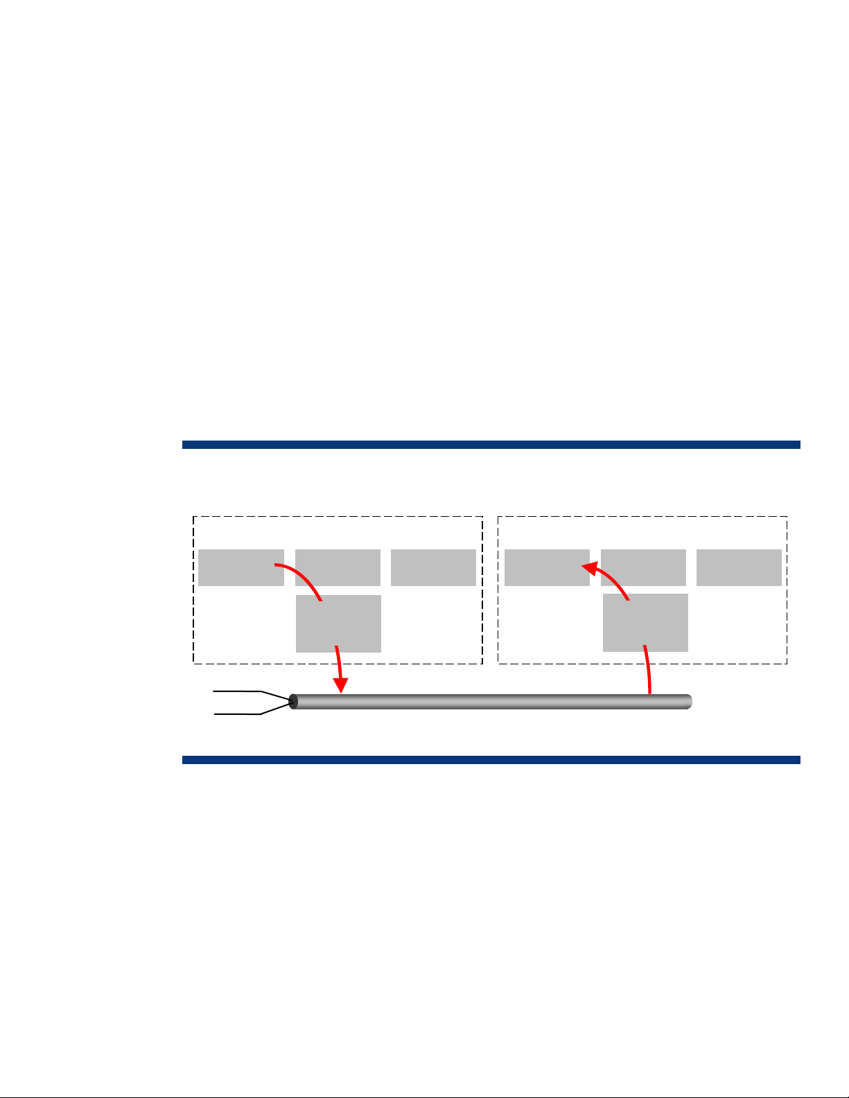
Figure 2. Data flow with RDMA over TCP (Ethernet)
Sending Host
Memory CPU
TX Pr
RX Pr
RDMA over TCP allows many classes of traffic (networking, I/O, file system and block storage, and
interprocess messaging) to share the same physical interconnect, enabling that physical interconnect
to become the single unifying data center fabric. RDMA over TCP provides more efficient network
communications, which can increase the scalability of processor-bound applications. RDMA over TCP
also leverages existing Ethernet infrastructures and the expertise of IT networking personnel.
Chipset
Ethernet
NIC
Memory
Ethernet LAN
Receiving Host
Chipset
Ethernet
NIC
CPU
4
Page 5

RDMA protocol overview
A series of protocols are layered to perform RDMA over TCP (Figure 3). The top three layers form the
iWARP family of protocols that provide high-speed internet operability. The RDMA protocol converts
RDMA write, RDMA read, and sends into Direct Data Placement (DDP) messages. The DDP protocol
segments outbound DDP messages into one or more DDP segments, and reassembles one or more
DDP segments into a DDP message. The marker-based, protocol-data-unit-aligned (MPA) protocol
adds a backward marker at a fixed interval to DDP segments and also adds a length and cyclical
redundancy check (CRC) to each MPA segment. TCP schedules outbound TCP segments and satisfies
delivery guarantees. IP adds necessary network routing information.
Figure 3. Protocol layers for RDMA over TCP
TX
RDMA
DDP
MPA
TCP
IP
TCP uses a stream of 8-bit fields (octets) to communicate data, while DDP uses fixed protocol data
units (PDUs). To enable RDMA, DDP needs a framing mechanism for the TCP transport protocol. MPA
is a marker-based PDU-aligned framing mechanism for the TCP protocol.
RX
Converts RDMA write, RDMA read, and sends into DDP
messages
Segments outbound (TX) DDP messages into one or more
DDP segments; reassembles one or more DDP segments
into a DDP message
Adds a backward marker at a fixed interval to DDP
segments; also adds a length and CRC to each MPA
segment
Schedules outbound TCP segments and satisfies delivery
guarantees
Adds necessary network routing information
MPA provides a generalized framing mechanism that enables a network adapter using DDP to locate
the DDP header. The adapter can then place the data directly in the application buffer, based on the
control information carried in the header. MPA enables this capability even when the packets arrive
out of order. By enabling DDP, MPA avoids the memory copy overhead and reduces the memory
requirement for handling out-of-order packets and dropped packets.
MPA creates a framed PDU (FPDU) by prefixing a header, inserting markers, and appending a CRC
after the DDP segment. MPA delivers the FPDU to TCP. The MPA-aware TCP sender puts the FPDUs
into the TCP stream and segments the TCP stream so that each TCP segment contains a single FPDU.
The MPA receiver locates and assembles complete FPDUs within the stream, verifies their integrity,
and removes information that is no longer necessary. MPA then provides the complete DDP segment
to DDP.
5
Page 6

DDP allows upper layer protocol (ULP) data, such as application messages or disk I/O, contained
within DDP segments to be placed directly into its final destination in memory without processing by
the ULP. This may occur even when the DDP segments arrive out of order.
A DDP segment is the smallest unit of data transfer for the DDP protocol. It includes a DDP header and
ULP payload. The DDP header contains control and placement fields that define the final destination
for the payload, which is the actual data being transferred.
A DDP message is a ULP-defined unit of data interchange that is subdivided into one or more DDP
segments. This segmentation may occur for a variety of reasons, including segmentation to respect the
maximum segment size of TCP. A sequence of DDP messages is called a DDP stream.
DDP uses two data transfer models: a tagged buffer model and an untagged buffer model.
A tagged buffer model is used to transfer tagged buffers between the two members of the transfer (the
local peer and the remote peer). A tagged buffer is explicitly advertised to the remote peer through
exchange of a steering tag (STag), tagged offset, and length. An STag is simply an identifier of a
tagged buffer on a node, and the tagged offset identifies the base address of the buffer. Tagged
buffers are typically used for large data transfers, such as large data structures and disk I/O.
An untagged buffer model is used to transfer untagged buffers from the local peer to the remote peer.
Untagged buffers are not explicitly advertised to the remote peer. Untagged buffers are typically used
for small control messages, such as operation and I/O status messages.
RDMA data transfer operations
The RDMA protocol provides seven data transfer operations. Except for the RDMA read operation,
each operation generates exactly one RDMA message. The RDMA information is included inside of
fields within the DDP header.
With an RDMA-aware network interface controller (RNIC), the data target and data source host
processors are not involved in the data transfer operations, so they can continue to do useful work.
The RNIC is responsible for generating outgoing and processing incoming RDMA packets: The data is
placed directly where the application advertises that it wants the data to go and is pulled from where
the application indicates the data is located. This eliminates the copies of data that occur in the
traditional operating system protocol stack on both the send and receive sides.
Send operations
RDMA uses four variations of the send operation:
• Send operation
• Send with invalidate operation
• Send with solicited event
• Send with solicited event and invalidate
A send operation transfers data from the data source (the peer sending the data payload) into a
buffer that has not been explicitly advertised by the data target (the peer receiving the data payload).
The send message uses the DDP untagged buffer model to transfer the ULP message into the untagged
buffer of the data target. Send operations are typically used to transfer small amounts of control data
where the overhead of creating an STag for DDP does not justify the small amount of memory
bandwidth consumed by the data copy.
The send with invalidate message includes all functionality of the send message, plus the capability to
invalidate a previously advertised STag. After the message has been placed and delivered at the data
target, the data target’s buffer identified by the STag included in the message can no longer be
accessed remotely until the data target’s ULP re-enables access and advertises the buffer again.
6
Page 7

The send with solicited event message is similar to the send message except that when the send with
solicited event message has been placed and delivered, an event (for example, an interrupt) may be
generated at the recipient, if the recipient is configured to generate such an event. This allows the
recipient to control the amount of interrupt overhead it will encounter.
The send with solicited event and invalidate message combines the functionality of the send with
invalidate message and the send with solicited event message.
RDMA write
An RDMA write operation uses an RDMA write message to transfer data from the data source to a
previously advertised buffer at the data target. The ULP at the data target enables the data target
tagged buffer for access and advertises the buffer’s size (length), location (tagged offset), and STag to
the data source through a ULP-specific mechanism such as a prior send message. The ULP at the data
source initiates the RDMA write operation. The RDMA write message uses the DDP tagged buffer
model to transfer the ULP message into the data target’s tagged buffer. The STag associated with the
tagged buffer remains valid until the ULP at the data target invalidates it or until the ULP at the data
source invalidates it through a send with invalidate operation or a send with solicited event with
invalidate operation.
RDMA read
The RDMA read operation transfers data to a tagged buffer at the data target from a tagged buffer at
the data source. The ULP at the data source enables the data source tagged buffer for access and
advertises the buffer’s size (length), location (tagged offset), and STag to the data target through a
ULP-specific mechanism such as a prior send message. The ULP at the data target enables the data
target tagged buffer for access and initiates the RDMA read operation. The RDMA read operation
consists of a single RDMA read request message and a single RDMA read response message, which
may be segmented into multiple DDP segments.
The RDMA read request message uses the DDP untagged buffer model to deliver to the data source’s
RDMA read request queue the STag, starting tagged offset, and length for both the data source and
the data target tagged buffers. When the data source receives this message, it then processes the
message and generates a read response message, which will transfer the data.
The RDMA read response message uses the DDP tagged buffer model to deliver the data source’s
tagged buffer to the data target, without any involvement from the ULP at the data source.
The data source STag associated with the tagged buffer remains valid until the ULP at the data source
invalidates it or until the ULP at the data target invalidates it through a send with invalidate or send
with solicited event and invalidate. The data target STag associated with the tagged buffer remains
valid until the ULP at the data target invalidates it.
Terminate
A terminate operation is included to perform an abortive tear down of the connection when an error
is encountered. The terminate operation transfers to the data target information associated with an
error that occurred at the data source. The terminate message uses the DDP untagged buffer model to
transfer the message into the data target’s untagged buffer.
Verbs
The RDMA Verbs Specification describes an abstract interface to an RNIC. The RNIC implements the
RDMA protocol over a reliable transport, such as MPA over TCP. The RDMA verbs provide a semantic
definition of the RNIC interface.
A verbs consumer uses the capabilities of the RNIC to accomplish some objective. A verbs consumer
may be defined as an operating system kernel thread, a non-privileged application, or a special
privileged process. RDMA provides verbs consumers the capability to control data placement,
7
Page 8

eliminate data copy operations, and significantly reduce communications overhead and latencies by
allowing one verbs consumer to place information directly in the memory of another verbs consumer,
while preserving operating system and memory protection semantics.
of elements used in RNIC operation, including privileged mode consumers, non-privileged mode
consumers, RNIC components, and the RNIC interface.
Figure 4. Model for RNIC operation
Figure 4 is a conceptual model
Application
OS
Kernel Agent
(RNIC Interface)
Kernel
Hardware
Interface
Hardware
QP
Privileged
Privileged Mode Agent
QP
Non-Privileged
Operating Environment Interface
Non-Privileged Mode Agent
CQ
QP
QP CQ
RNIC
RNIC interface
The RNIC interface provides coordination between the consumer of RNIC services and the RNIC.
Verbs specify behavior of the RNIC and enable creation and management of queue pairs,
management of the RNIC, management of work requests, and transfer of error indications from the
RNIC interface.
A fundamental function of the RNIC interface is management of the RNIC. This includes arranging
access to the RNIC, accessing and modifying its attributes, and shutting it down.
The Queue Pair (QP) is a key component required for the operation of the RNIC interface. It is the
RNIC resource used by consumers to submit work requests to the RNIC interface. A queue pair is used
to interact with an RDMA stream on an RNIC. There may be thousands of queue pairs per RNIC.
Each queue pair provides the consumer with a single point of access to an individual RDMA stream.
A Queue Pair consists of a send queue and a receive queue. Sends, RDMA reads, RDMA writes, and
other operations are posted to send queues through work requests. Receive queues contain the buffer
information for arriving send messages. Work requests provide the mechanism for consumers to place
work queue elements onto the send and receive queues of a queue pair.
The Completion Queue (CQ) allows the consumer to retrieve work request completion status.
Notification mechanisms are provided to help a consumer identify when work requests have
completed processing in the RNIC interface. There may be thousands of completion queues per RNIC,
and they can be associated with the send queues and receive queues in any combination the
consumer requires.
Event handlers provide the mechanism for notifying consumers of asynchronous events that occur
within the RNIC interface but cannot be reported through the completion queues because they are
asynchronous or they are not easily associated with a work completion.
8
Page 9

RDMA over InfiniBand
/
InfiniBand is a high-performance, low-latency alternative to Ethernet. InfiniBand architecture uses a
switched-fabric, channel-based design that adapts well to distributed-computing environments where
performance, infrastructure simplification, and convergence of component interconnects are key
design goals. A data center employing an InfiniBand infrastructure is less complex and easier to
manage.
Like Ethernet, InfiniBand architecture uses multi-layer processing to transfer data between nodes. Each
InfiniBand node contains a host or target channel adapter (HCA or TCA) that connects to an
InfiniBand network through a bi-directional serial link. However, InfiniBand architecture allows links to
have multiple channel pairs (4x being the current typical implementation), with each channel handling
virtual lanes of multiplexed data at a 2.5 Gbps single data rate (SDR). Additional nodes and channels
(up to 12x) and faster signaling (up to quad data rate) increase the bandwidth of a link, making an
InfiniBand infrastructure scalable with system expansion and capable of a bandwidth from 2.5 to 120
Gbps in each direction (although processor overhead and server I/O bus architectures may lower
usable bandwidth by 10 percent or more).
RDMA data transactions over InfiniBand (Figure 5) occur basically the same way as described for
Ethernet and offer the same advantages. However, InfiniBand uses a communications stack designed
to support RDMA as a core capability and therefore provides greater RDMA performance than
Ethernet.
Figure 5. RDMA data flow over InfiniBand
Sending Host
Memory CPU
Ch 1 TX/RX Prs
Ch 2 TX/RX Prs
Ch 3 TX
Ch 4 TX/RX Prs
RX Prs
Chipset
IB
Memory
4x InfiniBand Link
Receiving Host
Chipset
IB
CPU
An InfiniBand HCA is similar to an Ethernet NIC in operation but uses a different software
architecture. The InfiniBand HCA uses a separate communications stack usually provided by the HCA
manufacturer or by a third-party software vendor. Therefore, operating an HCA requires prior loading
of both the software driver and the communications stack for the specific operating system.
The majority of existing InfiniBand clusters run on Linux. Drivers and communications stacks are also
available for Microsoft® Windows®, HP-UX, Solaris, and other operating systems from various
hardware and software vendors. Note that specific feature support varies among operating systems
and vendors.
9
Page 10

InfiniBand uses a communications stack (Figure 6) that specifies both the functionality and physical
connectivity of the channel adapter. Adapter functionality is defined by its verb set as detected by the
application programming interface (API) of the operating system being used. Each layer is subservient
to the layer preceding it and must complete its function before passing the responsibility on to the next
layer.
Figure 6. InfiniBand communication layers
TX
Upper
Level
RX
Uses DAPL, SDD, and/or SRP protocols to handle RDMA
operations
Protocol
Transport
Network
Data Link
Physical
Processes information according to the operation specified
by the verb(s) invoked
Responsible for routing packets between subnets
Handles send and receive data at the packet level and
provides addressing, buffering, flow control, error
detection, and switching
Establishes the physical link, monitors link status, and
informs the data link layer when the link is up or down
InfiniBand RDMA protocols
The upper layer protocol (ULP) layer works closest to the operating system and application, and
defines how much (if any) software overhead will be required by the data transfer. A number of
InfiniBand upper layer protocols are available, three of which support RDMA operations:
• Direct Access Programming Library
• Sockets Direct Protocol
• SCSI RDMA Protocol
Direct Access Programming Library
The Direct Access Programming Library (DAPL) allows low-latency RDMA communications well-suited
for inter-node transfers. The uDAPL provides user-level access to RDMA functionality on InfiniBand.
Applications must be written with a specific uDAPL implementation to use RDMA for data transfers
between nodes. The kDAPL operates at the kernel level.
Sockets Direct Protocol
Sockets Direct Protocol (SDP) is a sockets-based RDMA protocol that operates from the kernel.
Applications must be written to take advantage of the SDP interface. SDP is based on the WinSock
Direct Protocol used by Microsoft server operating systems, and is suited for connecting databases to
application servers.
10
Page 11

SCSI RDMA Protocol
SCSI RDMA Protocol (SRP) encapsulates SCSI commands over InfiniBand for SAN networking.
Operating from the kernel level, SRP allows SCSI commands to be copied between systems via RDMA
for low-latency communications with storage systems.
InfiniBand link operation
Since some network devices can send data faster than the destination device can receive it, InfiniBand
uses a queue pair (one send, one receive) system similar to the one for RDMA over TCP. InfiniBand
queue pairs may be located in the HCA or TCA of each device or, if necessary, in main memory.
When a connection between two channel adapters is established, the transport layer’s
communications protocol is selected and queue pairs are assigned to a virtual lane.
The transport layer communications protocol can be implemented in hardware, allowing much of the
work to be off-loaded from the system’s processor. The transport layer can handle four types of data
transfers for the Send queue:
• Send/Receive – Typical operation where one node sends a message and another node receives the
message.
• RDMA Write – Operation where one node writes data directly into a memory buffer of a remote
node.
• RDMA Read – Operation where one node reads data directly from a memory buffer of a remote
node.
• RDMA Atomics – Combined operation of reading a memory location, comparing the value, and
changing/updating the value if necessary.
The only operation available for the receive queue is Post Receive Buffer transfer, which identifies a
buffer that a client may send to or receive from using a Send, RDMA Write, or RDMA Read data
transfer.
Conclusion
RDMA operations can provide iWARP functionality to today’s Ethernet networks and relieve the
congestion that 10-Gb Ethernet might otherwise cause. High-performance infrastructures such as
InfiniBand use RDMA as a core function to efficiently handle high data throughput that previously
required specialized networks.
HP is a founding member of the RDMA Consortium, an independent group formed to develop the
architectural specifications necessary to implement products that provide RDMA capabilities over
existing network interconnects. Many of the concepts and technologies leveraged for RDMA come
from high-end servers, such as HP NonStop and SuperDome servers, and from established networking
used in storage area networks (SANs) and local area networks (LANs). HP has led the development in
networking and communication technologies, including cluster interconnects such as ServerNet, the
Virtual Interface (VI) Architecture, and InfiniBand, which represent the origins and evolution of RDMA
technology.
Today, HP is at the forefront of the RDMA technology initiative and is a trusted advisor on future data
center directions that provide lasting value for IT customers. HP is committed to support RDMA as
applied to both Ethernet and InfiniBand infrastructures, and to help customers chose the most costeffective fabric interconnect solution for their environments.
11
Page 12

For more information
For more information on RDMA, go to the RDMA Consortium website at www.rdmaconsortium.org.
Call to action
Send comments about this paper to: TechCom@HP.com.
© 2006 Hewlett-Packard Development Company, L.P. The information contained
herein is subject to change without notice. The only warranties for HP products and
services are set forth in the express warranty statements accompanying such
products and services. Nothing herein should be construed as constituting an
additional warranty. HP shall not be liable for technical or editorial errors or
omissions contained herein.
Microsoft and Windows are registered trademarks of Microsoft Corporation.
TC060101TB, January 2006
 Loading...