

HP ProLiant BL280c User Manual

HP ProLiant BL280c G6 Server Blade
User Guide
Part Number 514028-001
March 2009 (First Edition)

© Copyright 2009 Hewlett-Packard Development Company, L.P.
The information contained herein is subject to change without notice. The only warranties for HP products and services are set forth in the express
warranty statements accompanying such products and services. Nothing herein should be construed as constituting an additional warranty. HP
shall not be liable for technical or editorial errors or omissions contained herein.
Microsoft, Windows, Windows NT, Windows XP, and Windows Server are U.S. registered trademarks of Microsoft Corporation.
Intel and Pentium are trademarks or registered trademarks of Intel Corporation or its subsidiaries in the United States and other countries.
AMD Athlon is a trademark of Advanced Micro Devices, Inc.
Java is a US trademark of Sun Microsystems, Inc.
Intended audience
This document is for the person who installs, administers, and troubleshoots servers and storage systems.
HP assumes you are qualified in the servicing of computer equipment and trained in recognizing hazards
in products with hazardous energy levels.

Contents
Component identification............................................................................................................... 7
Front panel components ............................................................................................................................. 7
Front panel LEDs and buttons ......................................................................................................................8
System board components.......................................................................................................................... 9
Mezzanine connector definitions ....................................................................................................... 9
DIMM slot locations .......................................................................................................................10
Hard drive connector identification ..................................................................................................10
System maintenance switch............................................................................................................. 10
HP c-Class Blade SUV Cable..................................................................................................................... 11
Operations................................................................................................................................. 13
Power up the server blade........................................................................................................................ 13
Power down the server blade.................................................................................................................... 13
Remove the server blade .......................................................................................................................... 14
Remove the access panel.......................................................................................................................... 15
Install the access panel............................................................................................................................. 15
Remove the air baffle............................................................................................................................... 15
Install the air baffle.................................................................................................................................. 15
Setup......................................................................................................................................... 17
Overview ...............................................................................................................................................17
Installing an HP BladeSystem c-Class enclosure ...........................................................................................17
Installing server blade options................................................................................................................... 17
Installing interconnect modules.................................................................................................................. 17
Interconnect bay numbering and device mapping.............................................................................. 18
Connecting to the network........................................................................................................................ 19
Installing a server blade ........................................................................................................................... 20
Completing the configuration.................................................................................................................... 21
Hardware options installation....................................................................................................... 22
Introduction ............................................................................................................................................ 22
Hard drive option.................................................................................................................................... 22
Processor option...................................................................................................................................... 24
Memory options...................................................................................................................................... 29
Memory subsystem architecture ....................................................................................................... 29
Single-, dual-, and quad-rank DIMMs ............................................................................................... 30
DIMM identification.......................................................................................................................30
Memory configurations................................................................................................................... 31
General DIMM slot population guidelines.........................................................................................33
Configuring the air baffle for DIMM installation................................................................................. 36
Installing a DIMM.......................................................................................................................... 37
Mezzanine card option............................................................................................................................ 38
HP Smart Array P712m Controller option ................................................................................................... 39
HP Trusted Platform Module option ............................................................................................................ 45
Installing the Trusted Platform Module board ..................................................................................... 46
Retaining the recovery key/password .............................................................................................. 47
Enabling the Trusted Platform Module............................................................................................... 47
Contents 3

Cabling ..................................................................................................................................... 49
SATA hard drive cabling.......................................................................................................................... 49
Optional SAS hard drive cabling .............................................................................................................. 49
Using the HP c-Class Blade SUV Cable ...................................................................................................... 50
Connecting locally to a server blade with video and USB devices.................................................................. 50
Accessing a server blade with local KVM .........................................................................................50
Accessing a server blade with local media devices ............................................................................ 51
Software and configuration utilities ............................................................................................... 53
Server blade deployment tools .................................................................................................................. 53
Software drivers and additional components..................................................................................... 53
HP BladeSystem c-Class Advanced management ............................................................................... 53
Network-based PXE deployment ...................................................................................................... 54
Deployment methods...................................................................................................................... 56
Configuration tools.................................................................................................................................. 59
SmartStart software........................................................................................................................ 59
HP ROM-Based Setup Utility............................................................................................................ 60
Array Configuration Utility.............................................................................................................. 62
Option ROM Configuration for Arrays .............................................................................................62
Re-entering the server serial number and product ID........................................................................... 63
Management tools................................................................................................................................... 63
Automatic Server Recovery .............................................................................................................63
ROMPaq utility.............................................................................................................................. 64
Integrated Lights-Out 2 technology................................................................................................... 64
Erase Utility ..................................................................................................................................64
StorageWorks library and tape tools................................................................................................ 64
HP Systems Insight Manager........................................................................................................... 65
Management Agents...................................................................................................................... 65
HP ProLiant Essentials Virtualization Management Software ................................................................65
HP ProLiant Essentials Vulnerability and Patch Management Pack ........................................................65
HP Insight Server Migration software for ProLiant...............................................................................66
HP ProLiant Essentials Performance Management Pack .......................................................................66
HP Insight Control Environment Suites............................................................................................... 67
HP Insight Control Linux Edition ....................................................................................................... 67
Redundant ROM support ................................................................................................................ 67
USB support and functionality ......................................................................................................... 68
Internal SD support ........................................................................................................................ 68
Diagnostic tools ...................................................................................................................................... 69
HP Insight Diagnostics.................................................................................................................... 69
HP Insight Diagnostics survey functionality ........................................................................................69
Integrated Management Log ...........................................................................................................69
Array Diagnostic Utility ..................................................................................................................70
Remote support and analysis tools............................................................................................................. 70
HP Insight Remote Support software ................................................................................................. 70
Keeping the system current ....................................................................................................................... 70
Drivers ......................................................................................................................................... 70
ProLiant Support Packs ................................................................................................................... 71
Operating system version support.................................................................................................... 71
HP Smart Update Manager............................................................................................................. 71
System Online ROM flash component utility ......................................................................................71
Change control and proactive notification ........................................................................................ 72
Care Pack ....................................................................................................................................72
Troubleshooting.......................................................................................................................... 73
Contents 4

Troubleshooting resources ........................................................................................................................73
Pre-diagnostic steps ................................................................................................................................. 73
Important safety information............................................................................................................ 74
Symptom information ..................................................................................................................... 75
Prepare the server for diagnosis ......................................................................................................75
Service notifications................................................................................................................................. 76
Loose connections ...................................................................................................................................76
Troubleshooting flowcharts .......................................................................................................................76
Start diagnosis flowchart ................................................................................................................77
General diagnosis flowchart ........................................................................................................... 78
Server blade power-on problems flowchart .......................................................................................80
POST problems flowchart ............................................................................................................... 82
OS boot problems flowchart ...........................................................................................................84
Server fault indications flowchart ..................................................................................................... 86
POST error messages and beep codes....................................................................................................... 88
Introduction to POST error messages................................................................................................ 88
209-Invalid Lockstep memory configuration.......................................................................................89
This DIMM does not support thermal monitoring... ............................................................................. 89
WARNING - iLO 2 not responding. System health monitoring has been disabled. ................................. 89
Battery replacement .................................................................................................................... 90
Regulatory compliance notices ..................................................................................................... 91
Regulatory compliance identification numbers............................................................................................. 91
Federal Communications Commission notice............................................................................................... 91
FCC rating label............................................................................................................................ 91
Class A equipment......................................................................................................................... 91
Class B equipment......................................................................................................................... 91
Declaration of conformity for products marked with the FCC logo, United States only....................................... 92
Modifications.......................................................................................................................................... 92
Cables................................................................................................................................................... 92
Canadian notice (Avis Canadien).............................................................................................................. 93
European Union regulatory notice .............................................................................................................93
Disposal of waste equipment by users in private households in the European Union......................................... 93
Japanese notice ...................................................................................................................................... 94
BSMI notice............................................................................................................................................ 94
Korean notice ......................................................................................................................................... 94
Chinese notice........................................................................................................................................ 95
Laser compliance .................................................................................................................................... 95
Battery replacement notice........................................................................................................................ 95
Taiwan battery recycling notice................................................................................................................. 96
Electrostatic discharge................................................................................................................. 97
Preventing electrostatic discharge.............................................................................................................. 97
Grounding methods to prevent electrostatic discharge.................................................................................. 97
Specifications............................................................................................................................. 98
Environmental specifications ..................................................................................................................... 98
Server blade specifications....................................................................................................................... 98
Technical support........................................................................................................................ 99
Before you contact HP.............................................................................................................................. 99
HP contact information............................................................................................................................. 99
Customer Self Repair ...............................................................................................................................99
Contents 5

Acronyms and abbreviations...................................................................................................... 107
Index....................................................................................................................................... 109
Contents 6
Component identification
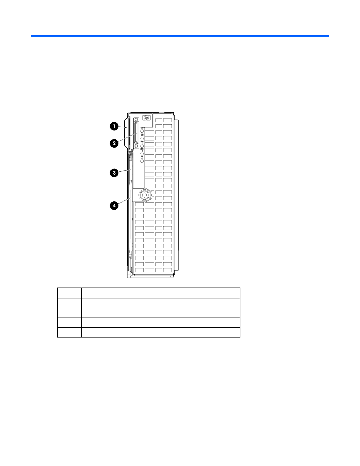
Front panel components
Item Description
1 Serial label pull tab
2 HP c-Class Blade SUV Cable connector
3 Release button
4 Server blade release lever
Component identification 7
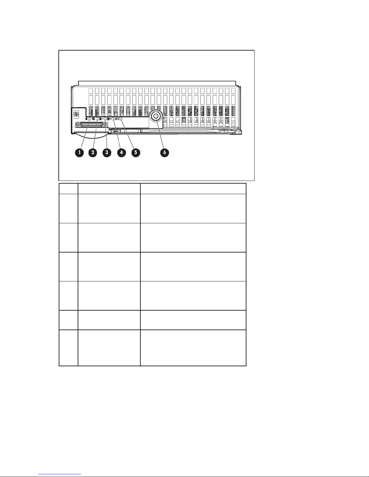
Front panel LEDs and buttons
Item Description Status
1 UID LED Blue = Identified
Blue flashing = Active remote management
Off = No active remote management
2 Health LED Green = Normal
Amber flashing = Degraded condition
Red flashing = Critical condition
3 NIC 1 LED Green = Network linked
Green flashing = Network activity
Off = No link or activity
4 NIC 2 LED Green = Network linked
Green flashing = Network activity
Off = No link or activity
5 Hard drive activity LED Green = Activity
Off = No activity
6 Power On/Standby
button and system
power LED
Green = On
Amber = Standby (auxiliary power
available)
Off = Off
Component identification 8
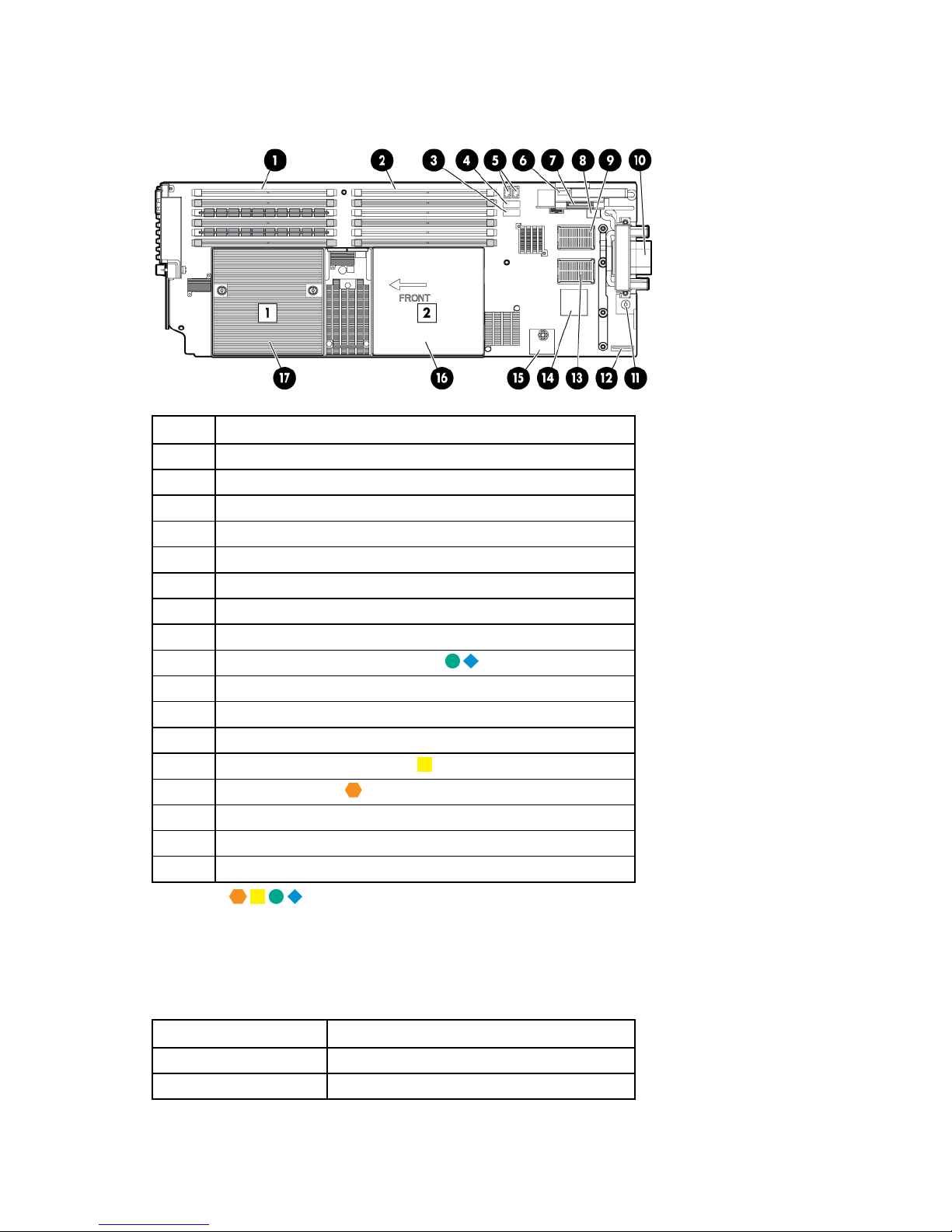
System board components
Item Description
1 Processor 1 DIMMs (6)
2 Processor 2 DIMMs (6)
3 SATA connector 2
4 SATA connector 1
5 Hard drive power connectors (2)
6 USB connector
7 SD card slot
8 System maintenance switch
9 Mezzanine connector 2 (Type I or II)
10 Enclosure connector
11 System board thumbscrew
12 System battery
13 Mezzanine connector 1 (Type I)
14 Embedded NICs (2)
15 TPM connector
16 Processor socket 2 (with blank)
17 Processor socket 1 (populated)
The symbols correspond to the symbols located on the interconnect bays. For more information, see the
HP ProLiant BL280c G6 Server Blade Installation Instructions that ship with the server blade.
Mezzanine connector definitions
A PCIe x8 mezzanine connector supports x16 cards at up to x8 speeds.
Item PCIe
Mezzanine connector 1 x8, Type I mezzanine card only
Mezzanine connector 2 x8, Type 1 or II mezzanine card
Component identification 9
DIMM slot locations
DIMM slots are numbered sequentially (1 through 6) for each processor. The supported AMP modes use
the letter assignments for population guidelines.
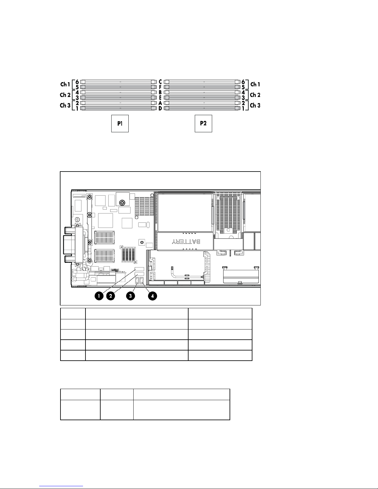
Hard drive connector identification
Item Description Connector color
1 SATA connector 2 Black
2 SATA connector 1 White
3 Hard drive power connector Black
4 Hard drive power connector Black
System maintenance switch
Position Default Function
S1 Off Off = iLO 2 security is enabled.
On = iLO 2 security is disabled.
Component identification 10
Position Default Function
S2 Off Off = System configuration can be
changed.
On = System configuration is
locked.
S3 Off Reserved
S4 Off Reserved
S5 Off Off = Power-on password is
enabled.
On = Power-on password is
disabled.
S6 Off Off = No function
On = Clear NVRAM
S7 — Reserved
S8 — Reserved
S9 — Reserved
S10 — Reserved
When the system maintenance switch position 6 is set to the On position, the system is prepared to erase
all system configuration settings from both CMOS and NVRAM.
CAUTION: Clearing CMOS and/or NVRAM deletes configuration information. Be sure to
properly configure the server or data loss could occur.
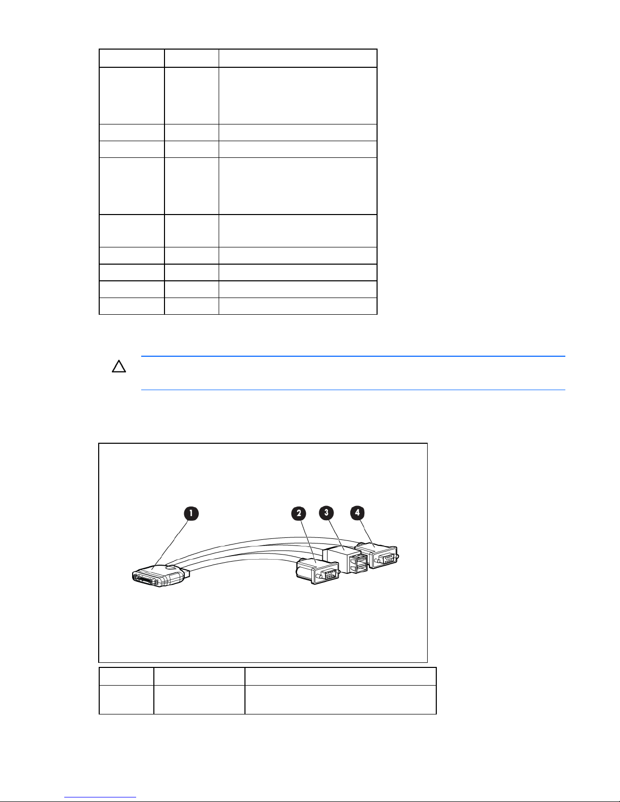
HP c-Class Blade SUV Cable
Item Connector Description
1 Server blade For connecting to the SUV connector on the
server blade front panel
Component identification 11

Item Connector Description
2 Video For connecting a video monitor
3 USB For connecting up to two USB devices
4 Serial For trained personnel to connect a null modem
serial cable and perform advanced diagnostic
procedures
Component identification 12

Operations
Power up the server blade
The Onboard Administrator initiates an automatic power-up sequence when the server blade is installed.
If the default setting is changed, use one of the following methods to power up the server blade:
• Use a virtual power button selection through iLO 2.
• Press and release the Power On/Standby button.
When the server blade goes from the standby mode to the full power mode, the system power LED
changes from amber to green.
For more information about the Onboard Administrator, see the enclosure setup and installation guide on
the HP website (http://www.hp.com/support
).
For more information about iLO 2, see "Integrated Lights-Out 2 technology (on page 64)."
Power down the server blade
Before powering down the server blade for any upgrade or maintenance procedures, perform a backup
of critical server data and programs.
Depending on the Onboard Administrator configuration, use one of the following methods to power down
the server blade:
• Use a virtual power button selection through iLO 2.
This method initiates a controlled remote shutdown of applications and the OS before the server
blade enter standby mode.
• Press and release the Power On/Standby button.
This method initiates a controlled shutdown of applications and the OS before the server blade enter
standby mode.
• Press and hold the Power On/Standby button for more than 4 seconds to force the server blade to
enter standby mode.
This method forces the server blade to enter standby mode without properly exiting applications and
the OS. It provides an emergency shutdown method in the event of a hung application.
• Execute one of the following commands using the Onboard Administrator CLI:
poweroff server all
or
poweroff server all force
The first command initiates a controlled shutdown of applications and the OS before the server blade
enter standby mode. The second form of the command forces the server blade to enter standby mode
without exiting applications and the OS. This is an emergency method to force a shutdown in the
event of a hung application.
Operations 13
• Use the Onboard Administrator GUI to initiate a shutdown:
a. Select the Enclosure Information tab, then select the Overall checkbox in the Device Bays item.
b. Initiate a shutdown from the Virtual Power menu:
— Select Momentary Press to initiate a controlled shutdown of applications and the OS.
— Select Press and Hold to initiate an emergency shutdown of applications and the OS.
IMPORTANT: When the server blade are in standby mode, auxiliary power is still being
provided. To remove all power from the server blade, remove the server blade from the
enclosure.
After initiating a virtual power down command, be sure that the server blade go into standby mode by
observing that the system power LED is amber.
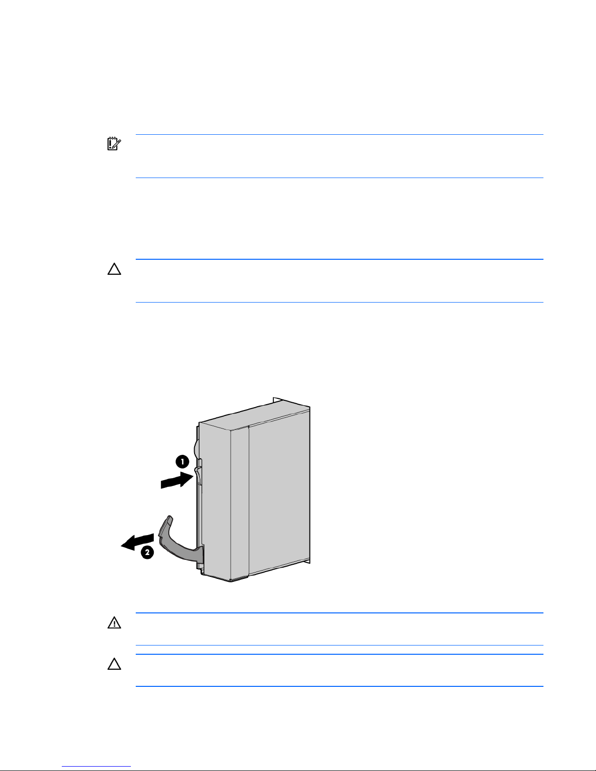
Remove the server blade
CAUTION: Do not use the server blade release lever to lift or carry the server blade. Always
support the weight of the server blade by handling the chassis directly. Improper use can
To remove the component:
1. Identify the proper server blade.
2. Power down the server blade (on page 13).
3. Remove the server blade.
damage the release lever and the server blade.
4. Place the server blade on a flat, level work surface.
WARNING: To reduce the risk of personal injury from hot surfaces, allow the drives and the
internal system components to cool before touching them.
CAUTION: To prevent damage to electrical components, properly ground the server blade
before beginning any installation procedure. Improper grounding can cause ESD.
Operations 14
Remove the access panel
To remove the component:
1. Power down the server blade (on page 13).
2. Remove the server blade (on page 14).
3. Press the access panel release button.
4. Slide the access panel towards the rear of the server blade, and then lift to remove the panel.
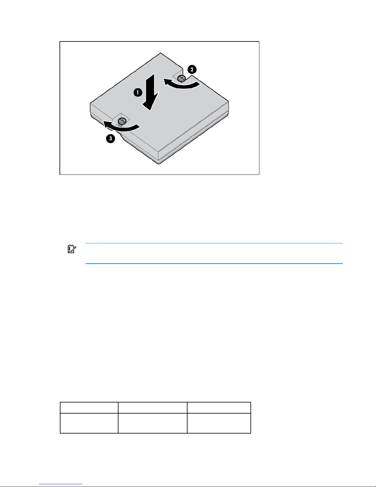
Install the access panel
1. Place the access panel on top of the server blade.
2. Slide the access panel forward until it clicks into place.
Remove the air baffle
1. Power down the server blade (on page 13).
2. Remove the server blade (on page 14).
3. Remove the access panel (on page 15).
4. If installed, disconnect the hard drive power and data cables from the system board.
5. Remove the air baffle.
Install the air baffle
IMPORTANT: To maintain proper airflow and prevent thermal damage, always install the air
baffle.
Operations 15
1. Install the air baffle.
2. If removed, connect the hard drive power and data cables to the system board ("Hard drive
connector identification" on page 10).
3. Install the access panel (on page 15).
4. Install the server blade ("Installing a server blade" on page 20).
Operations 16

Setup
Overview
Installation of a server blade requires the following steps:
1. Install and configure an HP BladeSystem c-Class enclosure.
2. Install any server blade options.
3. Install interconnect modules in the enclosure.
4. Connect the interconnect modules to the network.
5. Install a server blade.
6. Complete the server blade configuration.
For definitions of the acronyms used in this document, refer to "Acronyms and abbreviations" in the server
blade user guide.
Installing an HP BladeSystem c-Class enclosure
Before performing any server blade-specific procedures, install an HP BladeSystem c-Class enclosure.
The most current documentation for server blades and other HP BladeSystem components is available at
the HP website (http://www.hp.com/go/bladesystem/documentation
Documentation is also available in the following locations:
).
• Documentation CD that ships with the enclosure
• HP Business Support Center website (http://www.hp.com/support)
• HP Technical Documentation website (http://docs.hp.com)
Installing server blade options
Before installing and initializing the server blade, install any server blade options, such as an additional
processor, hard drive, or mezzanine card.
Installing interconnect modules
For specific steps to install interconnect modules, see the documentation that ships with the interconnect
module.
Setup 17
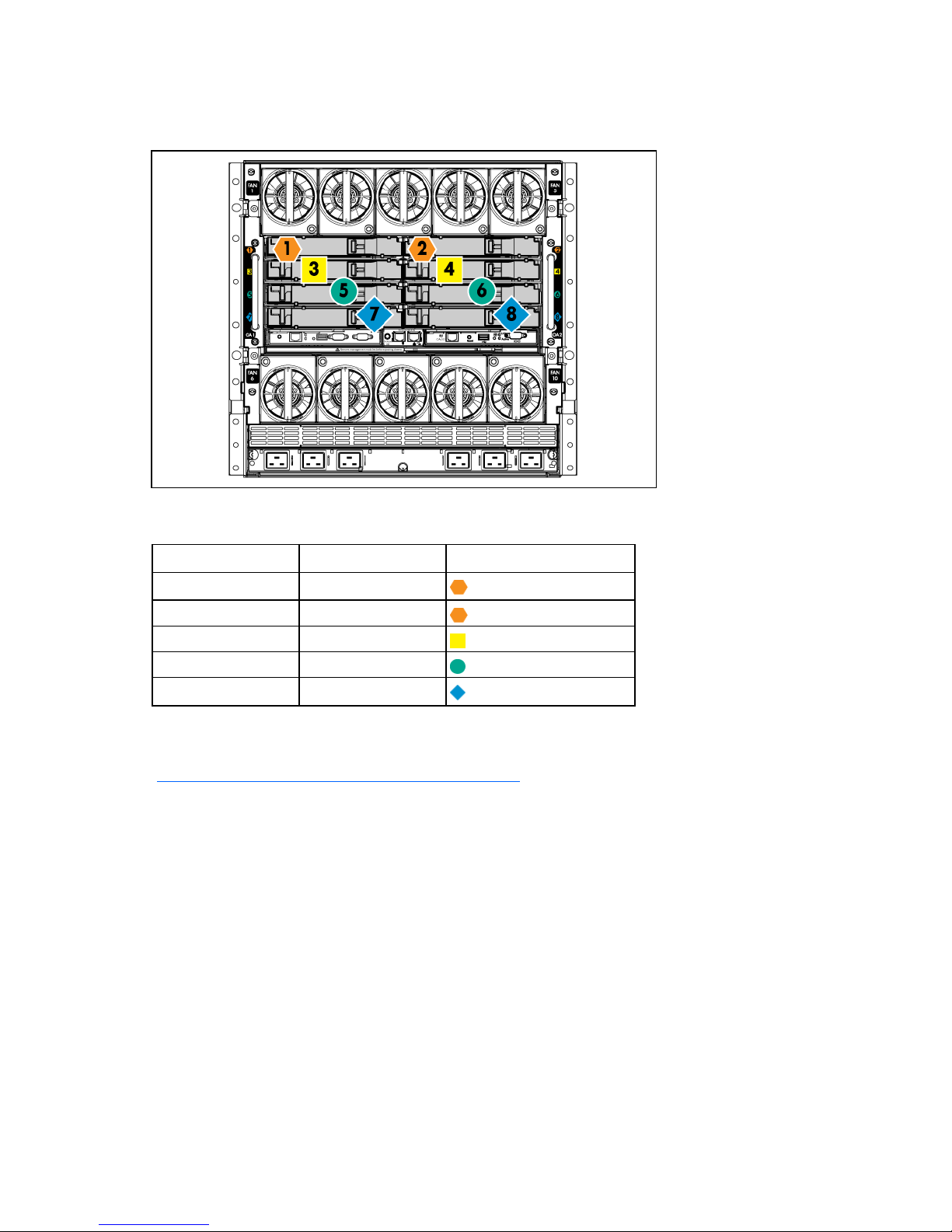
Interconnect bay numbering and device mapping
• HP BladeSystem c7000 Enclosure
To support network connections for specific signals, install an interconnect module in the bay
corresponding to the embedded NIC or mezzanine signals.
Server blade signal Interconnect bay Interconnect bay labels
NIC 1 (Embedded) 1
NIC 2 (Embedded) 2
Mezzanine 1 3 and 4
Mezzanine 2 5 and 6
7 and 8
For detailed port mapping information, see the HP BladeSystem enclosure installation poster or the
HP BladeSystem enclosure setup and installation guide on the HP website
(http://www.hp.com/go/bladesystem/documentation
).
Setup 18
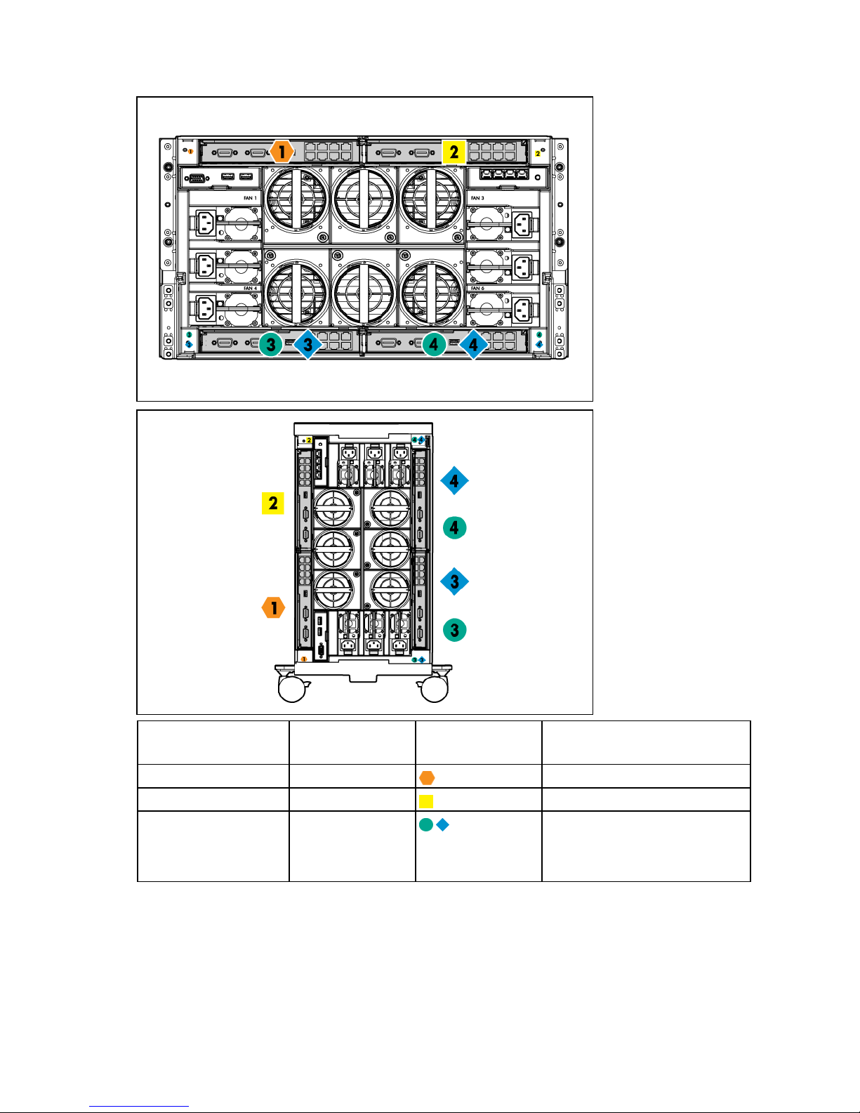
• HP BladeSystem c3000 Enclosure and Tower Enclosure
Server blade signal Interconnect bay
NICs 1, 2 (embedded) 1
Mezzanine 1 2
Mezzanine 2 3,4
Connecting to the network
To connect the HP BladeSystem to a network, each enclosure must be configured with network
interconnect devices to manage signals between the server blades and the external network.
number
Interconnect bay
label
Notes
—
Four port cards connect to bay 2
• Four port cards
• Ports 1 and 3 connect to bay 3
• Ports 2 and 4 connect to bay 4
Setup 19

Two types of interconnect modules are available for HP BladeSystem c-Class enclosures: Pass-thru modules
and switch modules. For more information about interconnect module options, see the HP website
(http://www.hp.com/go/bladesystem/interconnects
).
Installing a server blade
CAUTION: To prevent improper cooling and thermal damage, do not operate the enclosure
1. Remove the device bay blank.
2. Remove the enclosure connector cover.
unless all bays are populated with a component or a blank.
Setup 20
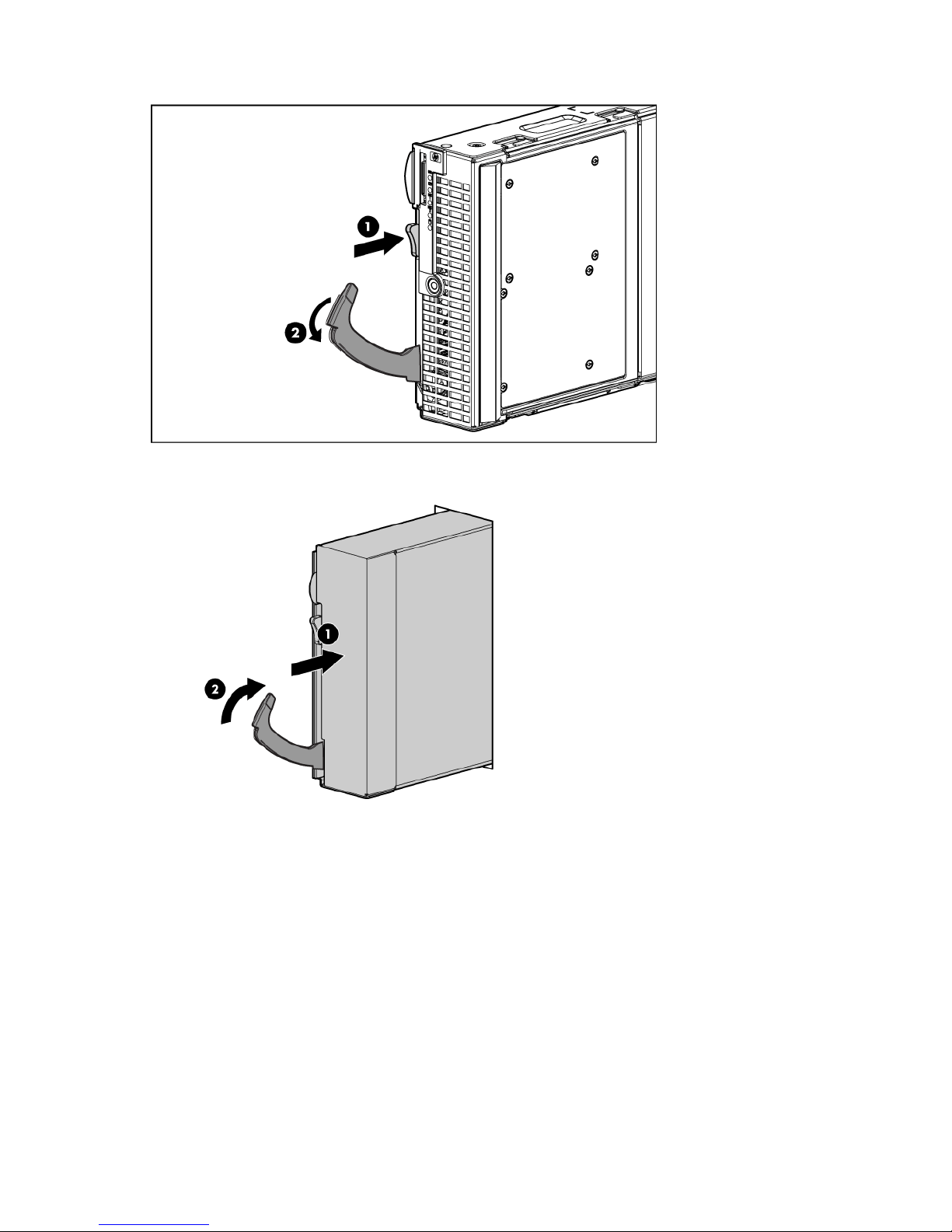
3. Prepare the server blade for installation.
4. Install the server blade.
Completing the configuration
To complete the server blade and HP BladeSystem configuration, see the overview card that ships with the
enclosure.
Setup 21

Hardware options installation
Introduction
If more than one option is being installed, read the installation instructions for all the hardware options
and identify similar steps to streamline the installation process.
WARNING: To reduce the risk of personal injury from hot surfaces, allow the drives and the
internal system components to cool before touching them.
CAUTION: To prevent damage to electrical components, properly ground the server before
beginning any installation procedure. Improper grounding can cause electrostatic discharge.
Hard drive option
The HP ProLiant BL280c G6 Server Blade supports midline SATA hard drives and 9.5-mm SATA hard
drives. SAS hard drives are supported when the HP Smart Array P712m Controller option is installed. The
HP Smart Array P712m Controller option does not support hard drive activity LEDs when installed in the
HP ProLiant BL280c G6 Server Blade.
For information on supported hard drive options and controller options, see the server blade QuickSpecs
on the HP website (http://www.hp.com
CAUTION: Failure to follow the hard drive installation guidelines can cause hardware
Always observe the installation guidelines:
• Always install a spacer when installing a 9.5-mm SATA hard drive.
• Be sure to use the proper screws when installing the hard drive:
To install the component:
damage.
o When installing a 9.5-mm SATA hard drive and a hard drive spacer, install the long hard drive
screws that are stored on the hard drive spacer.
o When installing a midline SATA hard drive or a SAS hard drive, install the standard hard drive
screws that ship with the server blade.
).
1. Power down the server blade (on page 13).
2. Remove the server blade (on page 14).
3. Remove the access panel (on page 15).
4. Remove the air baffle (on page 15).
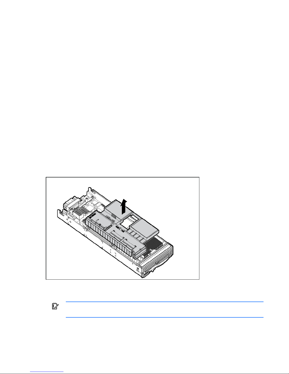
5. Install the hard drives.
Hardware options installation 22
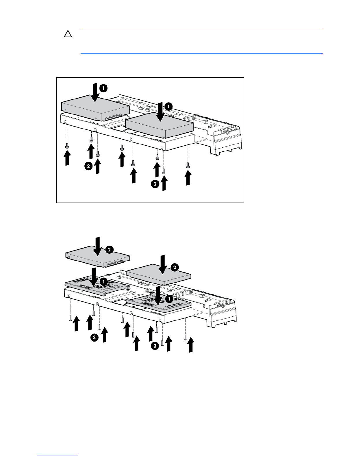
CAUTION: When installing midline SATA hard drives in the server blade, always install the
standard hard drive screws provided with the server blade. Installing the long hard drive
screws located on the hard drive spacer can damage the hard drive.
o Install the midline SATA hard drives. Secure the hard drives to the air baffle with the standard
hard drive screws.
o Install the SATA hard drives (9.5 mm) and hard drive spacers. Secure the hard drives and
spacers to the air baffle with the long hard drive screws. The long hard drive screws are stored
on the hard drive spacer.
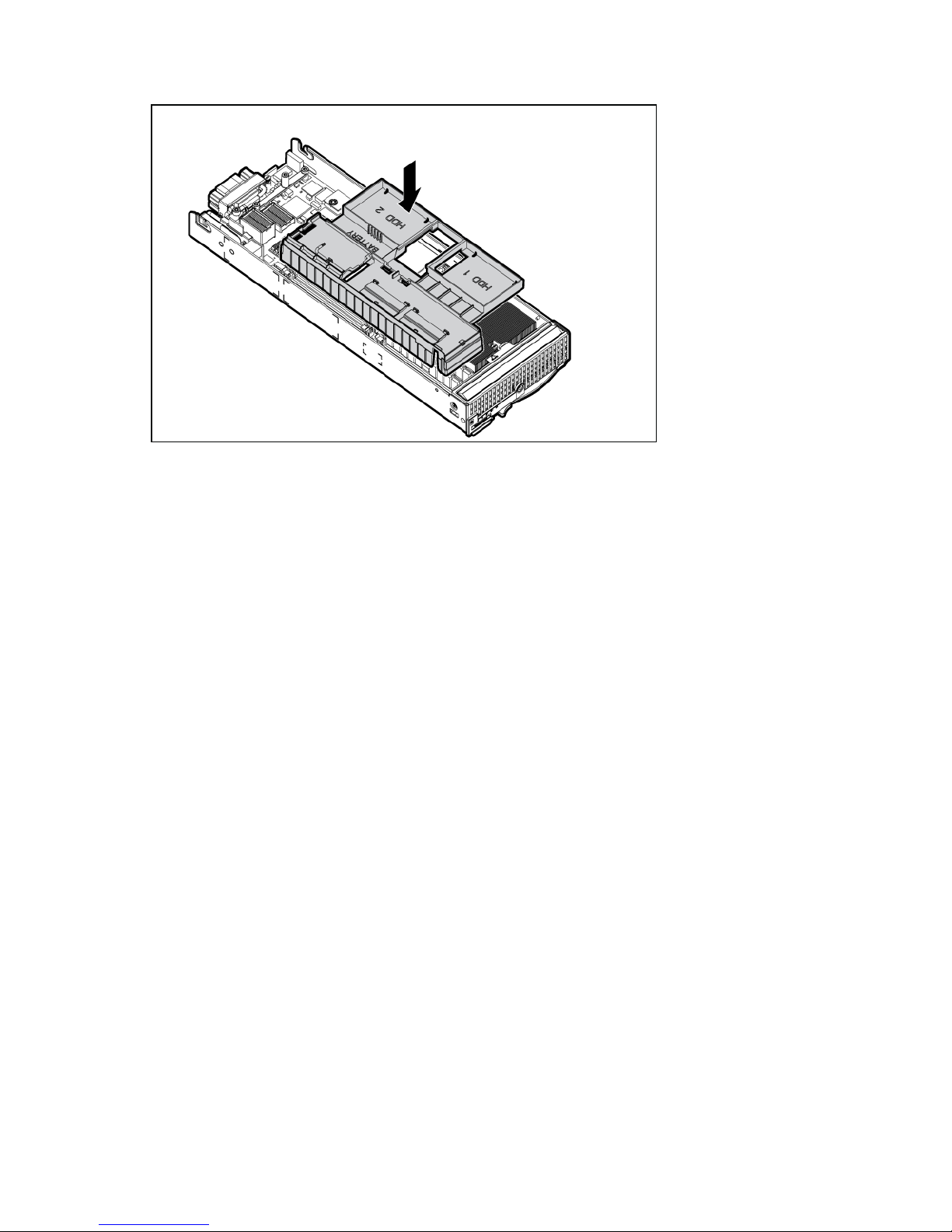
6. Connect hard drive cable 1 to hard drive 1.
7. Connect hard drive cable 2 to hard drive 2.
Hardware options installation 23
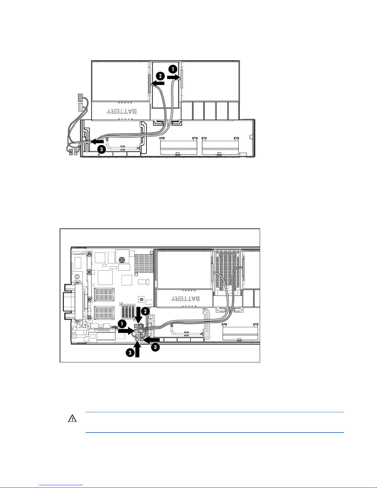
8. Route the cables through the air baffle.
9. Install the air baffle (on page 15).
10. Connect hard drive data cable 1 to SATA connector 1 on the system board.
11. Connect hard drive data cable 2 to SATA connector 2 on the system board.
12. Connect the hard drive power cables to the hard drive power connectors on the system board. The
power cables can connect to either of the hard drive power connectors on the system board.
13. Install the access panel (on page 15).
14. Install the server blade ("Installing a server blade" on page 20).
Processor option
WARNING: To reduce the risk of personal injury from hot surfaces, allow the drives and the
internal system components to cool before touching them.
Hardware options installation 24

CAUTION: To avoid damage to the system board:
• Do not touch the processor socket contacts.
• Always install the processor socket cover after removing the processor from the socket.
• Do not tilt or slide the processor when lowering the processor into the socket.
CAUTION: To avoid damage to the processor:
• Handle the processor only by the edges.
• Do not touch the bottom of the processor, especially the contact area.
CAUTION: To prevent possible server blade malfunction and damage to the equipment,
multiprocessor configurations must contain processors with the same part number.
CAUTION: To prevent possible server blade overheating, always populate processor socket 2
with a processor and a heatsink or a processor socket cover and a heatsink blank.
CAUTION: The heatsink thermal interface media is not reusable and must be replaced if the
heatsink is removed from the processor after it has been installed.
IMPORTANT: When installing the heatsink, align the guide pins on the processor retention
bracket with the alignment holes in the heatsink.
IMPORTANT: Processor socket 1 must always be populated. If processor socket 1 is empty, the
server blade does not power up.
NOTE: Do not discard the processor protective cover. Always install the processor protective
cover if the processor is removed from the socket.
IMPORTANT: When installing a processor with a faster speed or adding an additional
processor, update the system ROM before installing the processor.
To install the component:
1. Update the system ROM.
Locate and download the latest ROM version from the HP website (http://www.hp.com/support
Follow the instructions on the website to update the system ROM.
2. Power down the server blade (on page 13).
3. Remove the server blade (on page 14).
4. Remove the access panel (on page 15).
5. If installed, disconnect the hard drive power and data cables from the system board.
6. Remove the air baffle (on page 15).
7. Open the processor retaining latch and the processor socket retaining bracket.
).
Hardware options installation 25
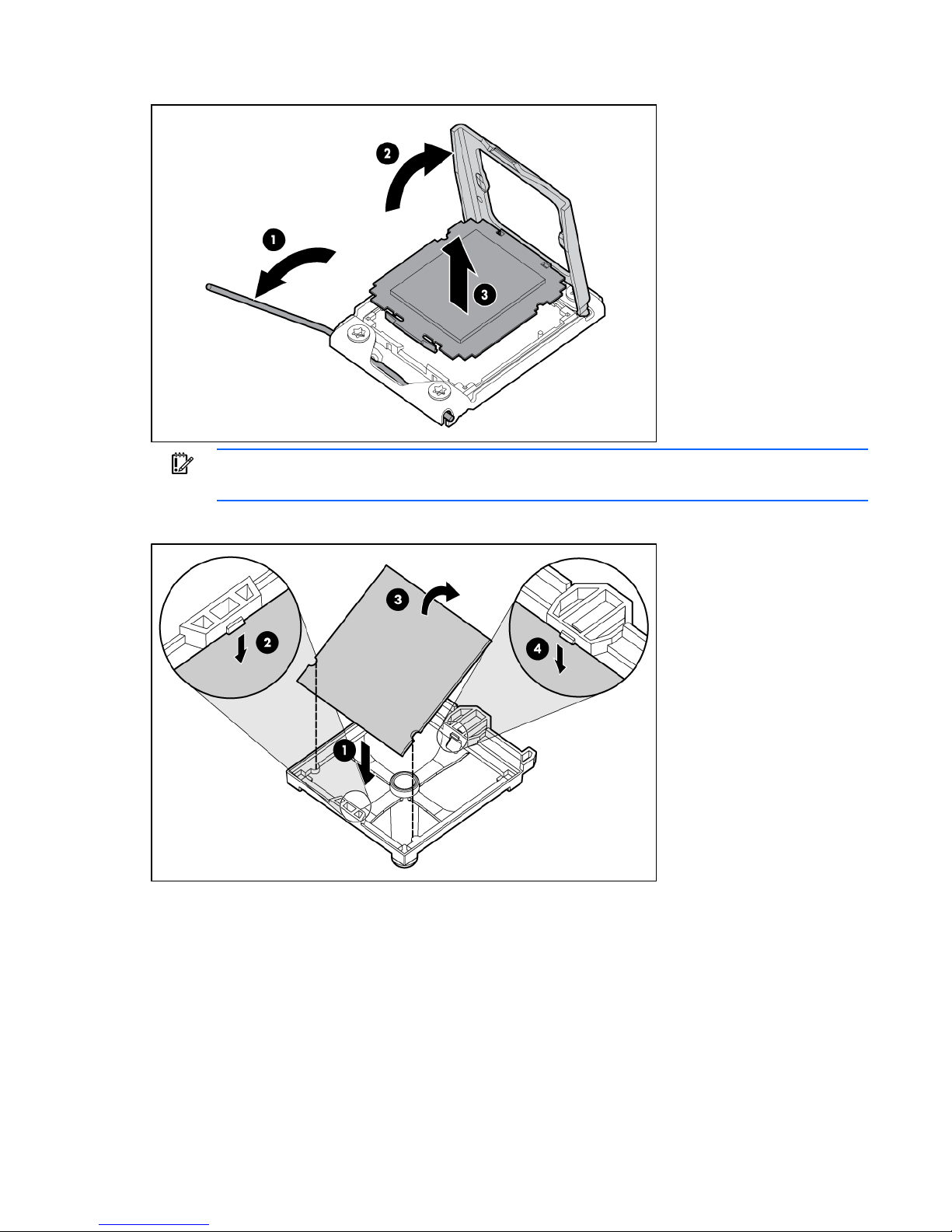
8. Remove the processor socket protective cover.
IMPORTANT: Be sure the processor remains inside the processor installation tool.
9. If the processor has separated from the installation tool, carefully re-insert the processor in the tool.
Hardware options installation 26
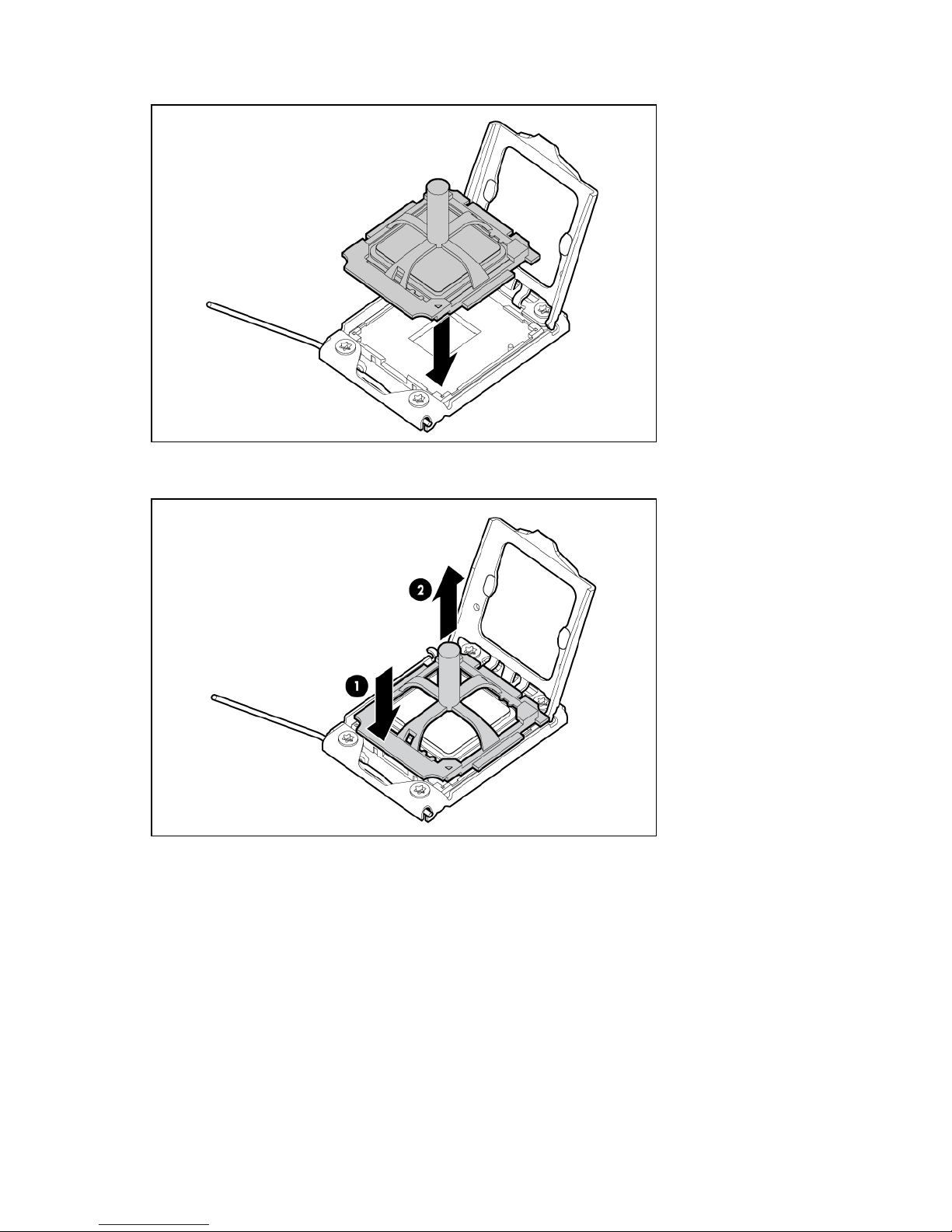
10. Align the processor installation tool with the socket and install the processor.
11. Press down firmly until the processor installation tool clicks and separates from the processor, and
then remove the processor installation tool.
Hardware options installation 27
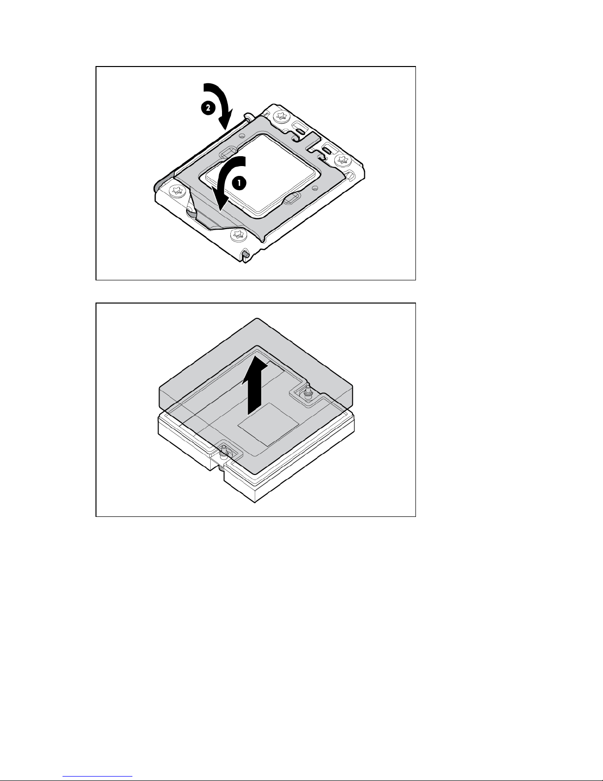
12. Close the processor socket retaining bracket and the processor retaining latch.
13. Remove the thermal interface protective cover from the heatsink.
Hardware options installation 28
14. Align and install the heatsink. Alternate tightening the screws until the heatsink is seated properly.
15. Install the air baffle (on page 15).
16. If removed, connect the hard drive power and data cables to the system board ("Hard drive
connector identification" on page 10).
17. Install the access panel (on page 15).
Memory options
IMPORTANT: This server blade does not support mixing RDIMMs and UDIMMs. Attempting to
mix these two types causes the server to halt during BIOS initialization.
The memory subsystem in this server blade can support RDIMMs or UDIMMs. Both types are referred to as
DIMMs when the information applies to both types. When specified as RDIMM or UDIMM, the
information applies to that type only. All memory installed in the server blade must be the same type.
The server blade supports the following DIMM speeds:
• Single- and dual-rank PC3-10600 (DDR-1333) DIMMs operating at 1333 and 1066 MHz
• Quad-rank PC3-8500 (DDR-1067) DIMMs operating at 1066 MHz
Depending on the processor model, the number of DIMMs installed, and whether UDIMMs or RDIMMs
are installed, the memory clock speed may be reduced to 1066 or 800 MHz. For more information on
Memory subsystem architecture
the effect of DIMM slot population, see "General DIMM slot population guidelines (on page 33)."
The memory subsystem in this server blade is divided into channels. Each processor supports three
channels, and each channel supports two DIMM slots, as shown in the following table.
Channel Slot Slot number
1 D A 1
2
Hardware options installation 29

Channel Slot Slot number
2 E B 3
4
3 F C 5
6
This multi-channel architecture provides enhanced performance in Advanced ECC mode. This architecture
also enables the Mirrored Memory and Lockstep memory modes. This server blade supports both
Registered PC3 DIMMs (RDIMMs) and Unbuffered DIMMs (UDIMMs).
DIMM slots in this server are identified by number and by letter. Letters identify the slots to populate for
specific AMP modes. Slot numbers are reported by ROM messages during boot and for error reporting.
Single-, dual-, and quad-rank DIMMs
To understand and configure memory protection modes properly, an understanding of single-, dual-, and
quad-rank DIMMs is helpful. Some DIMM configuration requirements are based on these classifications.
A single-rank DIMM has one set of memory chips that is accessed while writing to or reading from the
memory. A dual-rank DIMM is similar to having two single-rank DIMMs on the same module, with only
one rank accessible at a time. A quad-rank DIMM is, effectively, two dual-rank DIMMs on the same
module. Only one rank is accessible at a time. The server blade memory control subsystem selects the
proper rank within the DIMM when writing to or reading from the DIMM.
Dual- and quad-rank DIMMs provide the greatest capacity with the existing memory technology. For
example, if current DRAM technology supports 2-GB single-rank DIMMs, a dual-rank DIMM would be 4GB, and a quad-rank DIMM would be 8-GB.
DIMM identification
IMPORTANT: This server blade does not support mixing RDIMMs and UDIMMs. Attempting to
mix these two types causes the server to halt during BIOS initialization.
Hardware options installation 30
 Loading...