

HP ProLiant BL20p User Manual

HP ProLiant BL20p Generation 4 Server Blade User Guide
Part Number 405591-002
December 2006 (Second Edition)

© Copyright 2006 Hewlett-Packard Development Company, L.P.
The information contained herein is subject to change without notice. The only warranties for HP products and services are set forth in the express
warranty statements accompanying such products and services. Nothing herein should be construed as constituting an additional warranty. HP
shall not be liable for technical or editorial errors or omissions contained herein.
Microsoft and Windows are U.S. registered trademarks of Microsoft Corporation. Windows Server is a trademark of Microsoft Corporation.
AMD Athlon is a trademark of Advanced Micro Devices, Inc.
Intel and Pentium are trademarks or registered trademarks of Intel Corporation or its subsidiaries in the United States and other countries.
Java is a U.S. trademark of Sun Microsystems, Inc.
December 2006 (Second Edition)
Part Number 405591-002
Audience assumptions
This document is for the person who installs, administers, and troubleshoots servers and storage systems.
HP assumes you are qualified in the servicing of computer equipment and trained in recognizing hazards
in products with hazardous energy levels.

Contents
Component identification............................................................................................................... 6
Server blade components ........................................................................................................................... 6
Front panel components ................................................................................................................... 6
Front panel LEDs.............................................................................................................................. 7
Rear panel components .................................................................................................................... 8
SAS and SATA hard drive LEDs......................................................................................................... 8
SAS and SATA hard drive LED combinations....................................................................................... 9
Internal components....................................................................................................................... 10
System maintenance switch............................................................................................................. 11
Local I/O cable ...................................................................................................................................... 12
Server blade enclosure bay numbering ...................................................................................................... 12
iLO 2 connections ...................................................................................................................................13
Server blade enclosure compatibility.......................................................................................................... 13
Operations................................................................................................................................. 15
Power up the server blade ........................................................................................................................ 15
Power down the server blade.................................................................................................................... 15
Remove the server blade .......................................................................................................................... 16
Remove the access panel.......................................................................................................................... 16
Install the access panel............................................................................................................................. 17
Remove the air baffle............................................................................................................................... 17
Setup......................................................................................................................................... 19
Installing the HP BladeSystem components.................................................................................................. 19
Verifying system components .................................................................................................................... 19
Connecting to the network........................................................................................................................ 19
Installing server blade options................................................................................................................... 19
Installing a server blade ........................................................................................................................... 20
Completing the configuration .................................................................................................................... 20
Hardware options installation....................................................................................................... 21
Processor option...................................................................................................................................... 21
Memory option ....................................................................................................................................... 26
FBDIMM guidelines ....................................................................................................................... 26
Single- and dual-rank FBDIMMs....................................................................................................... 26
Installing FBDIMMs ........................................................................................................................ 27
Hard drive option.................................................................................................................................... 27
Multifunction network adapter option ......................................................................................................... 29
Fibre Channel mezzanine option............................................................................................................... 30
Interconnect options................................................................................................................................. 31
HP Smart Array Battery-Backed Write Cache Enabler option......................................................................... 31
Local I/O cabling ....................................................................................................................... 33
Using the local I/O cable......................................................................................................................... 33
Local administration using iLO 2 ............................................................................................................... 33
Connecting locally to a server blade with video and USB devices.................................................................. 34
Accessing a server blade with local KVM .........................................................................................34
Contents 3

Accessing local media devices ........................................................................................................ 35
Configuration and utilities............................................................................................................ 37
Server blade deployment tools .................................................................................................................. 37
Software drivers and additional components..................................................................................... 37
ProLiant p-Class Advanced management .......................................................................................... 37
Network-based PXE deployment ...................................................................................................... 38
Static IP bay configuration .............................................................................................................. 40
Deployment methods...................................................................................................................... 40
Configuration tools .................................................................................................................................. 44
SmartStart software........................................................................................................................ 44
HP ROM-Based Setup Utility............................................................................................................ 44
Array Configuration Utility .............................................................................................................. 46
Option ROM Configuration for Arrays .............................................................................................46
Re-entering the server serial number and product ID ........................................................................... 46
Management tools................................................................................................................................... 47
Automatic Server Recovery ............................................................................................................. 47
ROMPaq utility.............................................................................................................................. 47
Integrated Lights-Out 2 technology................................................................................................... 47
HP Systems Insight Manager ........................................................................................................... 48
Management Agents...................................................................................................................... 48
Redundant ROM support ................................................................................................................ 48
USB support.................................................................................................................................. 48
Diagnostic tools ...................................................................................................................................... 49
HP Insight Diagnostics.................................................................................................................... 49
Integrated Management Log ...........................................................................................................49
Remote support and analysis tools ............................................................................................................. 50
HP Instant Support Enterprise Edition................................................................................................ 50
Web-Based Enterprise Service......................................................................................................... 50
Open Services Event Manager ........................................................................................................ 50
Keeping the system current ....................................................................................................................... 50
Drivers ......................................................................................................................................... 50
ProLiant Support Packs ................................................................................................................... 51
Operating system version support.................................................................................................... 51
System online ROM flash component utility .......................................................................................51
Change control and proactive notification ........................................................................................ 51
Care Pack .................................................................................................................................... 51
Troubleshooting .......................................................................................................................... 52
Troubleshooting resources ........................................................................................................................52
Pre-diagnostic steps ................................................................................................................................. 52
Important safety information............................................................................................................ 52
Symptom information ..................................................................................................................... 54
Prepare the server for diagnosis ...................................................................................................... 55
Service notifications................................................................................................................................. 55
Loose connections ................................................................................................................................... 55
Troubleshooting flowcharts .......................................................................................................................56
Start diagnosis flowchart ................................................................................................................56
General diagnosis flowchart ........................................................................................................... 57
Server blade power-on problems flowchart .......................................................................................59
POST problems flowchart ............................................................................................................... 61
OS boot problems flowchart ...........................................................................................................63
Server fault indications flowchart ..................................................................................................... 65
POST error messages and beep codes ....................................................................................................... 67
Contents 4

Battery replacement .................................................................................................................... 68
Regulatory compliance notices ..................................................................................................... 69
Regulatory compliance identification numbers............................................................................................. 69
Federal Communications Commission notice............................................................................................... 69
FCC rating label............................................................................................................................ 69
Class A equipment......................................................................................................................... 70
Class B equipment......................................................................................................................... 70
Declaration of conformity for products marked with the FCC logo, United States only....................................... 70
Cables................................................................................................................................................... 71
Modifications.......................................................................................................................................... 71
European Union regulatory notice ............................................................................................................. 71
Disposal of waste equipment by users in private households in the European Union ......................................... 71
Canadian notice (Avis Canadien).............................................................................................................. 72
Japanese notice ...................................................................................................................................... 72
BSMI notice............................................................................................................................................ 72
Korean notice ......................................................................................................................................... 73
Battery replacement notice........................................................................................................................ 73
Taiwan battery recycling notice................................................................................................................. 73
Electrostatic discharge................................................................................................................. 75
Preventing electrostatic discharge .............................................................................................................. 75
Grounding methods to prevent electrostatic discharge.................................................................................. 75
Specifications............................................................................................................................. 76
Environmental specifications ..................................................................................................................... 76
Server specifications ................................................................................................................................ 76
Technical support........................................................................................................................ 77
Before you contact HP.............................................................................................................................. 77
HP contact information............................................................................................................................. 77
Customer Self Repair ............................................................................................................................... 77
Acronyms and abbreviations........................................................................................................ 85
Index......................................................................................................................................... 89
Contents 5
Component identification
In this section
Server blade components .......................................................................................................................... 6
Local I/O cable ..................................................................................................................................... 12
Server blade enclosure bay numbering ..................................................................................................... 12
iLO 2 connections .................................................................................................................................. 13
Server blade enclosure compatibility ........................................................................................................ 13
Server blade components
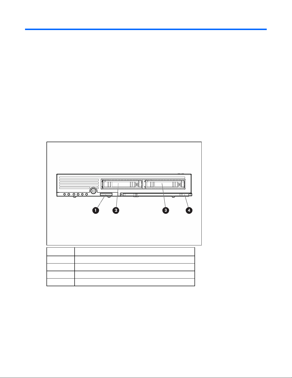
Front panel components
Item Description
1 I/O port*
2 Hot-plug SAS or SATA hard drive bay 1
3 Hot-plug SAS or SATA hard drive bay 2
4 Server blade handle
* The I/O port is used with the local I/O cable to perform some server blade configuration and diagnostic
procedures.
Component identification 6
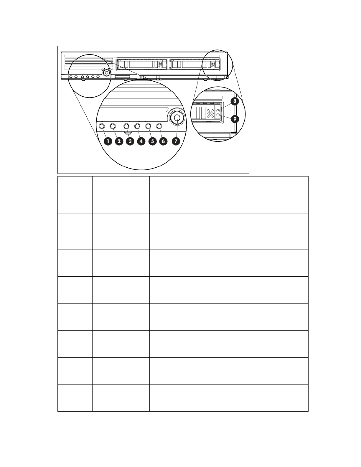
Front panel LEDs
Item Description Status
1 UID LED Blue = Identified
Blue flashing = Active remote management
Off = No active remote management
2 Health LED Green = Normal
Green flashing = Booting
Amber = Degraded condition
Red = Critical condition
3 NIC 1 LED* Green = Network linked
Green flashing = Network activity
Off = No link or activity
4 NIC 2 LED* Green = Network linked
Green flashing = Network activity
Off = No link or activity
5 NIC 3 LED* Green = Network linked
Green flashing = Network activity
Off = No link or activity
6 NIC 4 LED* Green = Network linked
Green flashing = Network activity
Off = No link or activity
7 System power LED Green = On
Amber = Standby (auxiliary power available)
Off = Off
8 Fault/UID Blue = Unit ID
Amber flashing = Drive failure
Off = Not in management mode
Component identification 7
Item Description Status
9 Drive activity Green = Active online condition
* Actual NIC numeration depends on several factors, including the operating system installed on the server blade.
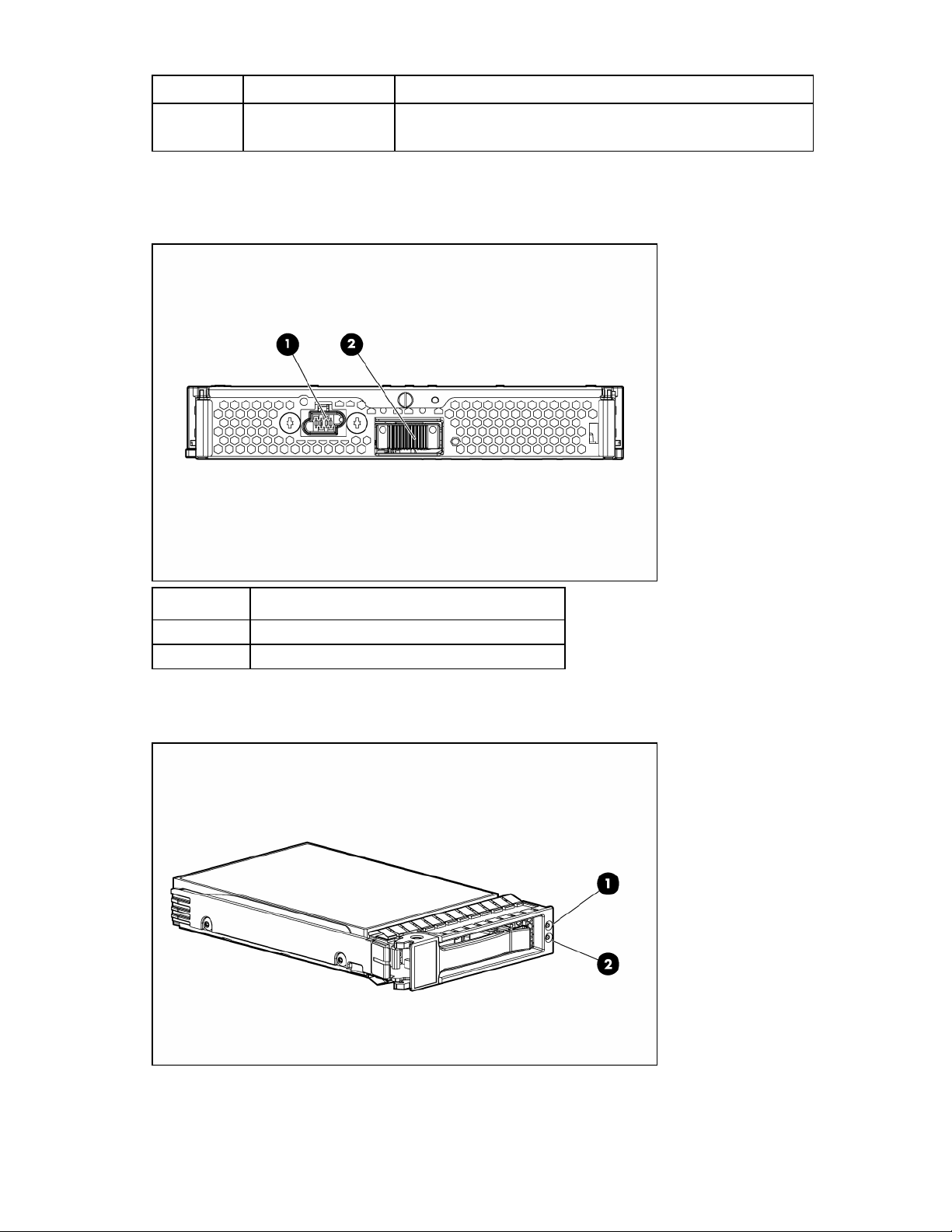
Rear panel components
Off = Inactive online condition
Item Description
1 Power connector
2 Signal connector
SAS and SATA hard drive LEDs
Component identification 8

Item Description
1 Fault/UID LED (amber/blue)
2 Online LED (green)
SAS and SATA hard drive LED combinations
Online/activity
LED (green)
On, off, or flashing
On, off, or flashing Steadily blue
On
On Off The drive is online, but it is not active currently.
Flashing regularly
(1 Hz)
Flashing regularly
(1 Hz)
Flashing irregularly
Flashing irregularly Off The drive is active, and it is operating normally.
Off Steadily amber
Off
Off Off
Fault/UID LED
(amber/blue)
Alternating amber
and blue
Amber, flashing
regularly (1 Hz)
Amber, flashing
regularly (1 Hz)
Off
Amber, flashing
regularly (1 Hz)
Amber, flashing
regularly (1 Hz)
Interpretation
The drive has failed, or a predictive failure alert has been
received for this drive; it also has been selected by a
management application.
The drive is operating normally, and it has been selected by a
management application.
A predictive failure alert has been received for this drive.
Replace the drive as soon as possible.
Do not remove the drive. Removing a drive may terminate the
current operation and cause data loss.
The drive is part of an array that is undergoing capacity
expansion or stripe migration, but a predictive failure alert has
been received for this drive. To minimize the risk of data loss, do
not replace the drive until the expansion or migration is
complete.
Do not remove the drive. Removing a drive may terminate the
current operation and cause data loss.
The drive is rebuilding, or it is part of an array that is undergoing
capacity expansion or stripe migration.
The drive is active, but a predictive failure alert has been
received for this drive. Replace the drive as soon as possible.
A critical fault condition has been identified for this drive, and
the controller has placed it offline. Replace the drive as soon as
possible.
A predictive failure alert has been received for this drive.
Replace the drive as soon as possible.
The drive is offline, a spare, or not configured as part of an
array.
Component identification 9
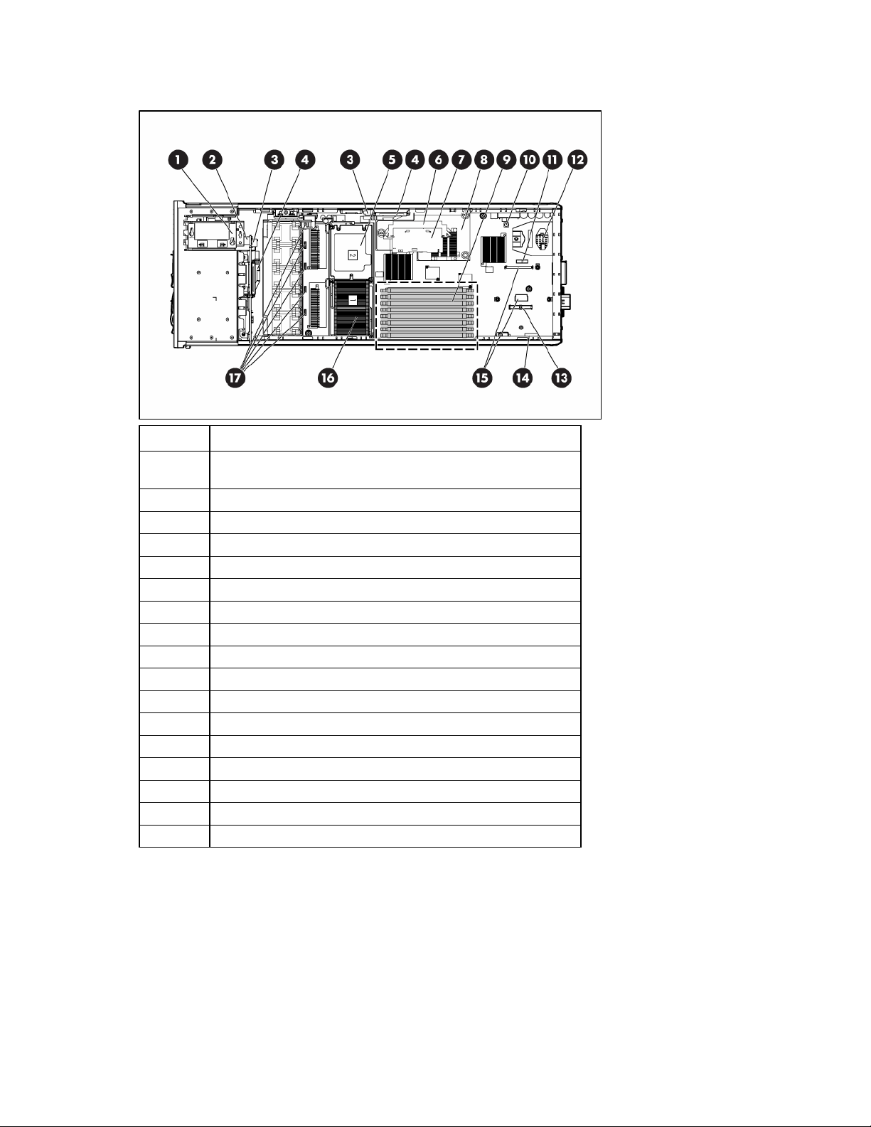
Internal components
Item Description
1
2 Internal USB connector
3 SAS backplane power connectors (2)
4 SAS backplane connectors (2)
5 Processor socket 2
6 HP Smart Array E200i Controller cache module connector
7 HP Smart Array E200i Controller cache module
8 HP Smart Array E200i Controller
9 FBDIMM slots 1-8
10 NMI switch
11 System battery
12 Power converter module
13 NIC mezzanine connector
14 System maintenance switch (SW4)
15 Fibre Channel adapter connectors
16 Processor socket 1 (populated)
17 Fan connectors
HP Smart Array SAS/SATA Battery-Backed Write Cache enabler
(optional)
Component identification 10
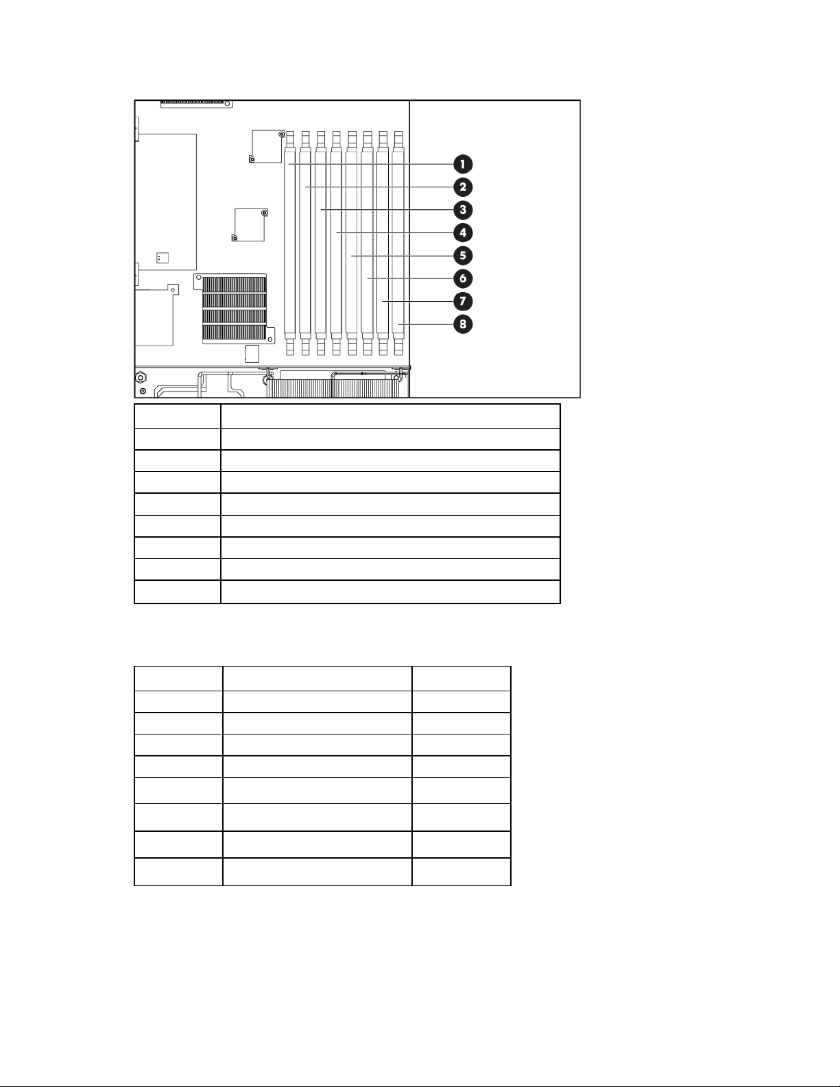
FBDIMM slots
Item Description
1 FBDIMM slot 1A
2 FBDIMM slot 2C
3 FBDIMM slot 3A
4 FBDIMM slot 4C
5 FBDIMM slot 5B
6 FBDIMM slot 6D
7 FBDIMM slot 7B
8 FBDIMM slot 8D
System maintenance switch
Position Function Default
1* iLO 2 security override Off
2 Configuration lock Off
3 Reserved Off
4 Reserved Off
5* Password disabled Off
6* Reset configuration Off
7 Reserved Off
8 Reserved Off
*To access redundant ROM, set S1, S5, and S6 to ON.
Component identification 11
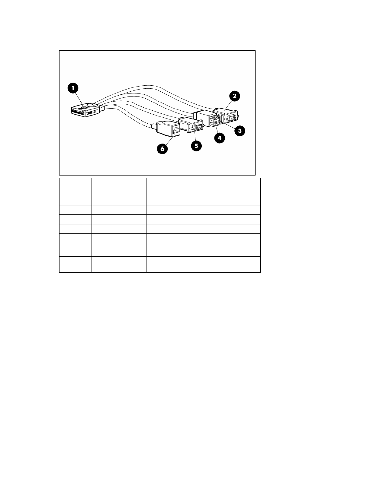
Local I/O cable
Item Connector Description
1 Local I/O
2 Video For connecting a video monitor
3 USB 1 For connecting a USB device
4 USB 2 For connecting a USB device
5 Serial
6
iLO 2 RJ-45
(10/100 Ethernet)
For connecting to the local I/O port on the
server blade front panel
For trained personnel to connect a null modem
serial cable and perform advanced diagnostic
procedures
For connecting an Ethernet to the server blade
iLO 2 interface from a client device
Server blade enclosure bay numbering
Each server blade enclosure requires a pair of interconnect modules to provide network access for data
transfer. Resolve bay numbering before determining connections between the server blades and
interconnects.
Component identification 12
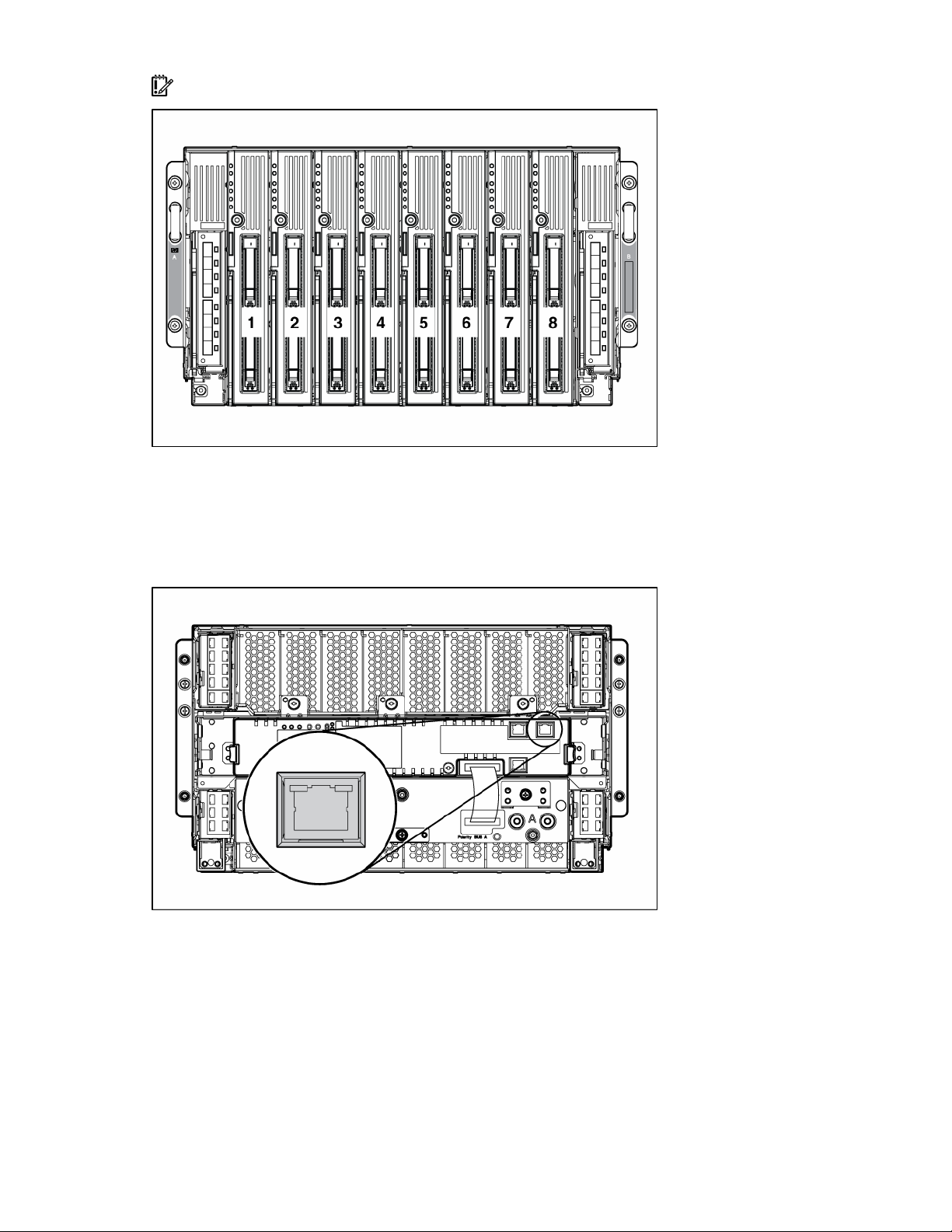
IMPORTANT: When looking at the rear of the enclosure, server blade bay numbering is reversed.
iLO 2 connections
An iLO 2 connector resides on the server blade management module of the enhanced server blade
enclosure. This RJ-45 connector enables remote manageability for each server blade in the enhanced
server blade enclosure.
For more information about the enhanced server blade enclosure, refer to the HP ProLiant BL p-Class
Server Blade Enclosure Upgrade Installation Guide or the HP ProLiant BL p-Class Server Blade Enclosure
Installation Guide.
Server blade enclosure compatibility
Certain configurations of the HP ProLiant BL20p server blade may require the support of an HP
BladeSystem p-Class server blade enclosure with enhanced backplane components (enhanced Server
Component identification 13

Blade Enclosure). For information on the compatibility of server blade enclosures, refer to the HP website
(http://www.hp.com/go/bladesystem/enclosure/compatibility
).
Component identification 14

Operations
In this section
Power up the server blade....................................................................................................................... 15
Power down the server blade .................................................................................................................. 15
Remove the server blade ......................................................................................................................... 16
Remove the access panel ........................................................................................................................ 16
Install the access panel ........................................................................................................................... 17
Remove the air baffle.............................................................................................................................. 17
Power up the server blade
By default, the server blade is set to power up automatically when installed in the server blade enclosure.
Be sure the server blade is compatible with the server blade enclosure. Refer to "Server blade enclosure
compatibility (on page 13)."
If the default setting is changed, use one of the following methods to power up the server blade:
• Press the Power On/Standby button on the server blade front panel.
o A momentary press initiates a power-up request. The server blade determines power availability
from the power subsystem. If required power is available, the server blade powers up.
o A press of 5 seconds or more initiates a power-up override. The server blade powers up without
power availability detection from the system.
CAUTION: Always observe iLO 2 alerts before initiating a power-up override to prevent a hot-plug
power supply fault and possible loss of system power. For more information, refer to the HP
Integrated Lights-Out User Guide.
NOTE: You can perform a server blade power-up override when the management modules are not in
use to manage the power-up request. Be sure that sufficient power is available.
• Use the virtual power button features in iLO 2.
o A momentary power-up selection
o A hold power-up selection
For more information about iLO 2, refer to "Configuration and utilities (on page 37)."
Power down the server blade
Power down the server blade using either of the following methods:
• Press the Power On/Standby button on the server blade front panel.
Be sure that the server blade is in standby mode by observing that the system power LED is amber.
This process may take 30 seconds, during which time some internal circuitry remains active.
• Use the virtual power button feature in iLO 2.
After initiating a manual or virtual power down command, be sure that the server blade goes into
standby mode by observing that the system power LED is amber.
Operations 15
IMPORTANT: When the server blade is in standby mode, auxiliary power is still being provided. To
remove all power from the server blade, remove the server blade from the server blade enclosure.
IMPORTANT: Remote power procedures require the most recent firmware for the power enclosure
and server blade enclosure management modules. For the most recent firmware, refer to the HP
website (http://www.hp.com/go/support
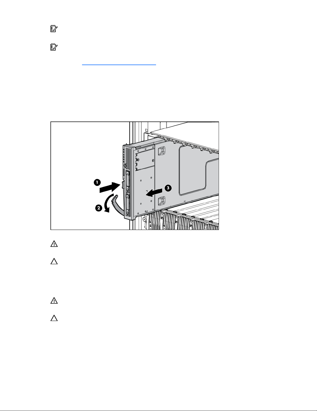
Remove the server blade
1. Identify the proper server blade in the server blade enclosure.
2. Back up all server blade data.
3. Power down the server blade (on page 15).
4. Remove the server blade from the server blade enclosure.
).
5. Place the server blade on a flat, level work surface.
WARNING: To reduce the risk of personal injury from hot surfaces, allow the drives and the internal
system components to cool before touching them.
CAUTION: To prevent damage to electrical components, properly ground the server blade before
beginning any installation procedure. Improper grounding can cause ESD.
Remove the access panel
WARNING: To reduce the risk of personal injury from hot surfaces, allow the drives and the internal
system components to cool before touching them.
CAUTION: To prevent damage to electrical components, properly ground the server blade before
beginning any installation procedure. Improper grounding can cause ESD.
1. Identify the proper server blade in the server blade enclosure.
2. Back up all server blade data.
3. Power down the server blade (on page 15).
4. Remove the server blade (on page 16).
5. Loosen the screw on the rear of the access panel.
Operations 16
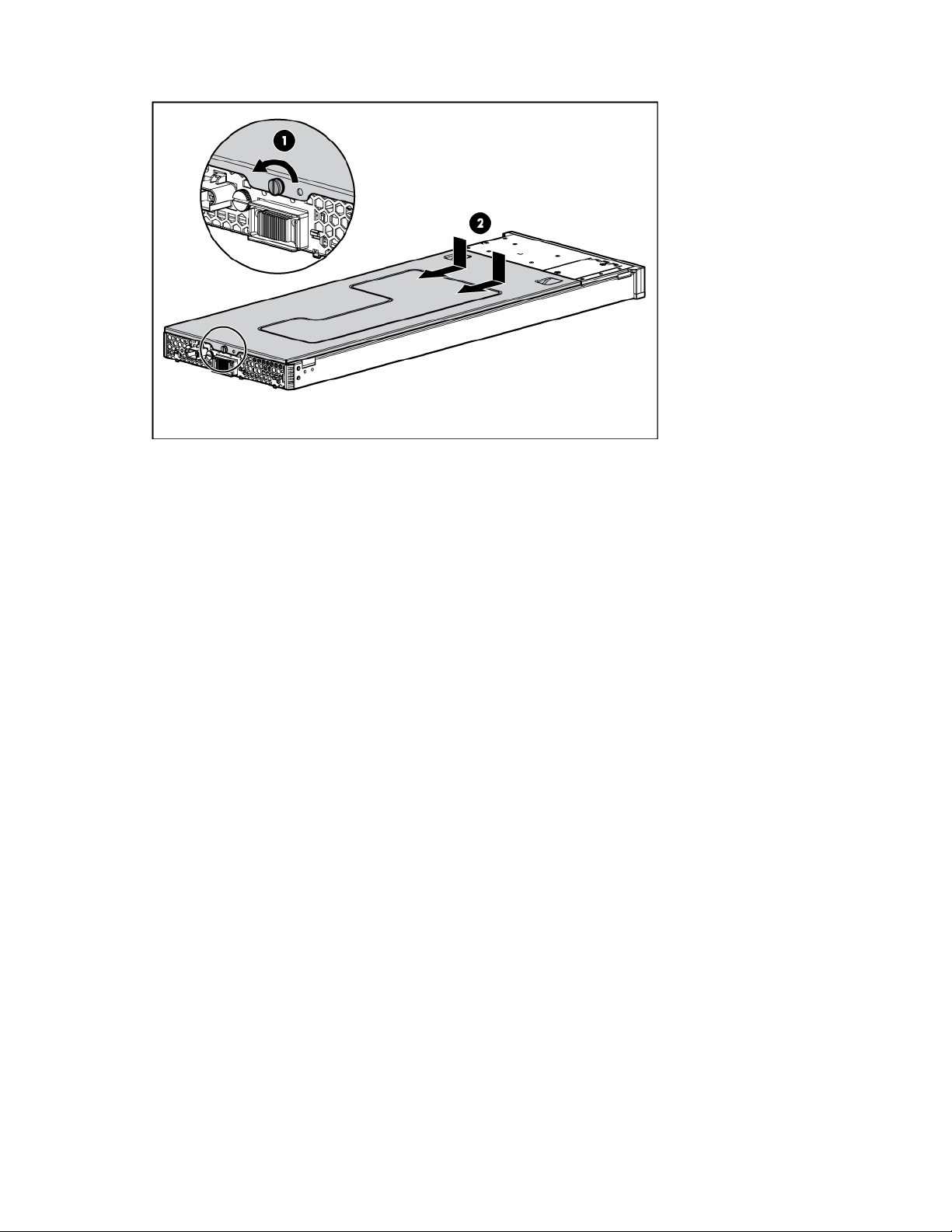
Remove the access panel.
6.
Install the access panel
1. Place the access panel on top of the server blade, allowing it to extend past the rear of the server
approximately 10 mm (0.39 in).
2. Slide the access panel forward to lock, and tighten the captive screw to secure the access panel to
the server.
Remove the air baffle
To remove the component:
1. Power down the server blade (on page 15).
2. Remove the server blade (on page 16).
3. Remove the access panel (on page 16).
Operations 17
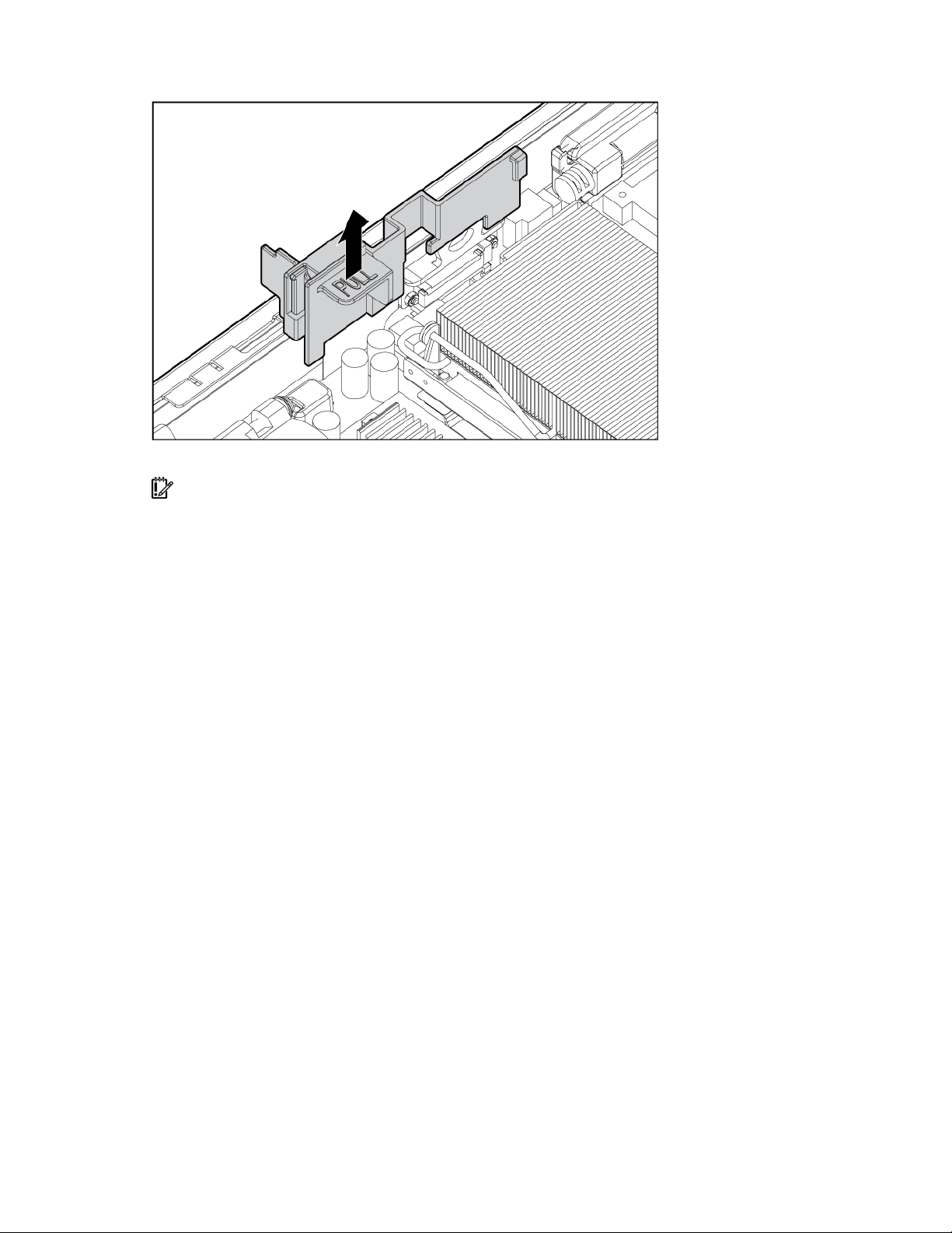
Remove the air baffle.
4.
To replace the component, reverse the removal procedure.
IMPORTANT: To ensure proper cooling, be sure the correct processor air baffle is installed at all
times.
Operations 18

Setup
In this section
Installing the HP BladeSystem components................................................................................................. 19
Verifying system components ................................................................................................................... 19
Connecting to the network....................................................................................................................... 19
Installing server blade options.................................................................................................................. 19
Installing a server blade .......................................................................................................................... 20
Completing the configuration................................................................................................................... 20
Installing the HP BladeSystem components
Before performing any server blade-specific procedures, install the HP BladeSystem components in your
environment. Refer to the hardware installation and configuration poster that ships with the server blade
enclosure.
The most current documentation for server blades and other HP BladeSystem p-Class components is
available at the HP website (http://www.hp.com/products/servers/proliant-bl/p-class/info
Documentation is also available in the following locations:
• Documentation CD that ships with the server blade enclosure
• HP Business Support Center website (http://www.hp.com/support)
• HP Technical Documentation website (http://docs.hp.com)
Verifying system components
1. Verify that the proper server blade enclosure is installed for the server blade. Refer to "Server blade
enclosure compatibility (on page 13)."
2. Verify that adequate power is available. Refer to the HP BladeSystem p-Class power calculator on
the HP website (http://www.hp.com/go/bladesystem/powercalculator
Connecting to the network
To connect the HP BladeSystem to a network, each server blade enclosure must be configured with a pair
of network interconnects to manage signals between the server blades and the external network. For more
information about interconnect options, refer to the HP website
(http://www.hp.com/go/bladesystem/interconnects
For network cabling connections for the server blade, refer to the HP ProLiant BL20p Generation 4 Server
Blade Installation Instructions that ship with the server blade.
).
).
).
Installing server blade options
Before installing and initializing the server blade, install any hardware options, such as an additional
processor or hard drives. For server blade options installation information, refer to "Hardware options
installation (on page 21)."
Setup 19
Installing a server blade
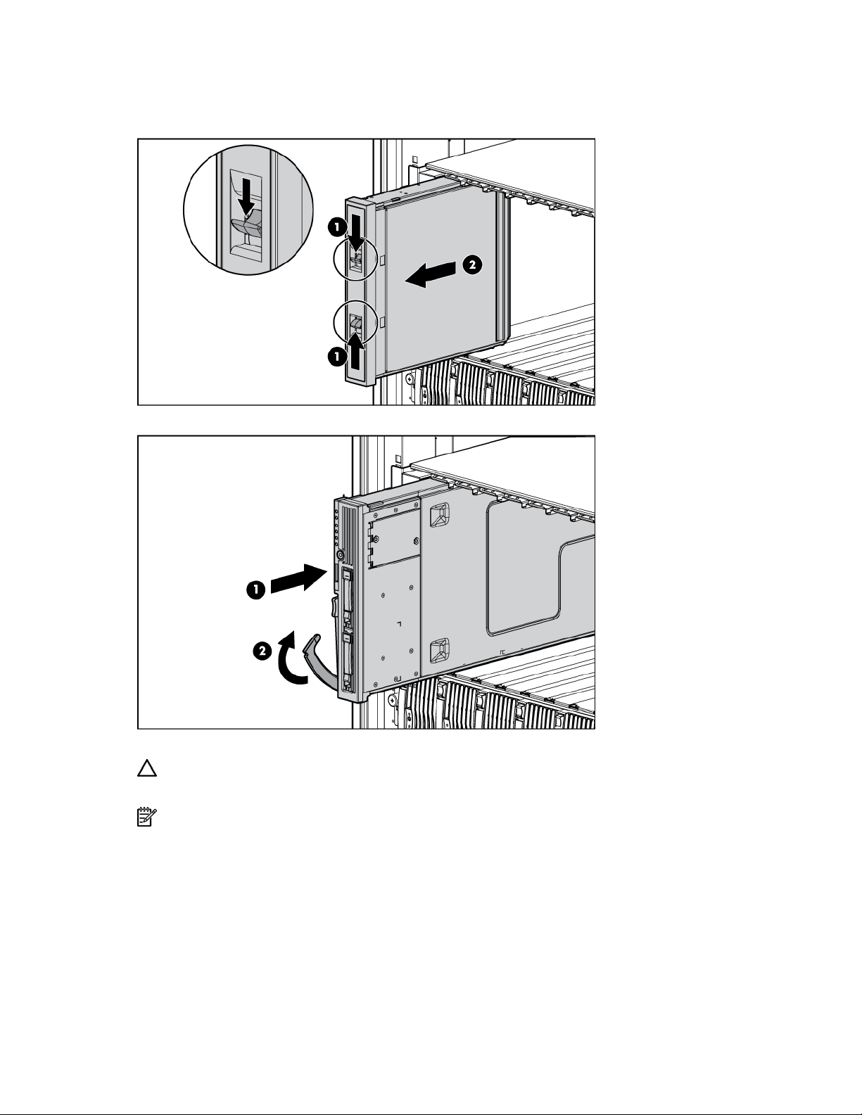
1. Remove a 6U server blade blank.
2. Install the server blade. When the server blade is fully inserted, it locks into place.
The default setting for server blades initiates automatic power up.
CAUTION: To prevent improper cooling and thermal damage, do not operate the server blade
enclosure unless all bays are populated with either a component or a blank.
NOTE: The first server blade must be installed into a server blade enclosure to facilitate naming the
server blade enclosure, the rack, and the interconnects. Complete the system configuration before
installing additional server blades.
Completing the configuration
To complete the server blade and HP BladeSystem configuration, refer to the hardware installation and
configuration poster that ships with the server blade enclosure.
Setup 20

Hardware options installation
In this section
Processor option..................................................................................................................................... 21
Memory option ...................................................................................................................................... 26
Hard drive option................................................................................................................................... 27
Multifunction network adapter option........................................................................................................ 29
Fibre Channel mezzanine option ............................................................................................................. 30
Interconnect options................................................................................................................................ 31
HP Smart Array Battery-Backed Write Cache Enabler option ....................................................................... 31
Processor option
The server blade supports dual-processor operation. With two processors installed, the server blade
supports boot functions through the processor installed in processor socket 1. However, if processor 1
fails, the system automatically boots from processor 2 and provides a processor failure message.
CAUTION: Removal of the processor or heatsink renders the thermal layer between the processor
and heatsink useless. A new heatsink must be ordered and installed before reinstalling the processor.
IMPORTANT: Processor socket 1 must be populated at all times or the server blade does not function.
CAUTION: To prevent possible server blade overheating, always populate processor socket 2 with a
processor and a heatsink or a processor cover and a heatsink blank.
To install the component:
1. Power down the server blade (on page 15).
2. Remove the server blade (on page 16).
3. Remove the access panel (on page 16).
4. Remove the processor blank.
Hardware options installation 21
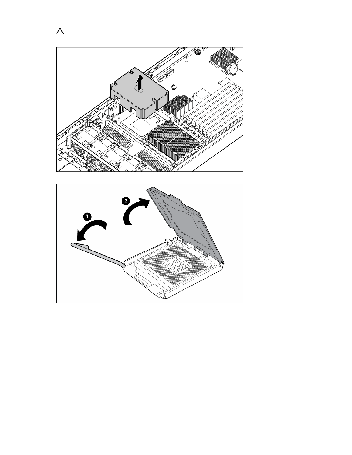
CAUTION: To prevent possible server blade overheating, always populate processor socket 2 with a
processor and a heatsink or a processor cover and a heatsink blank.
5. Open the processor retaining latch and the processor socket retaining bracket.
Hardware options installation 22
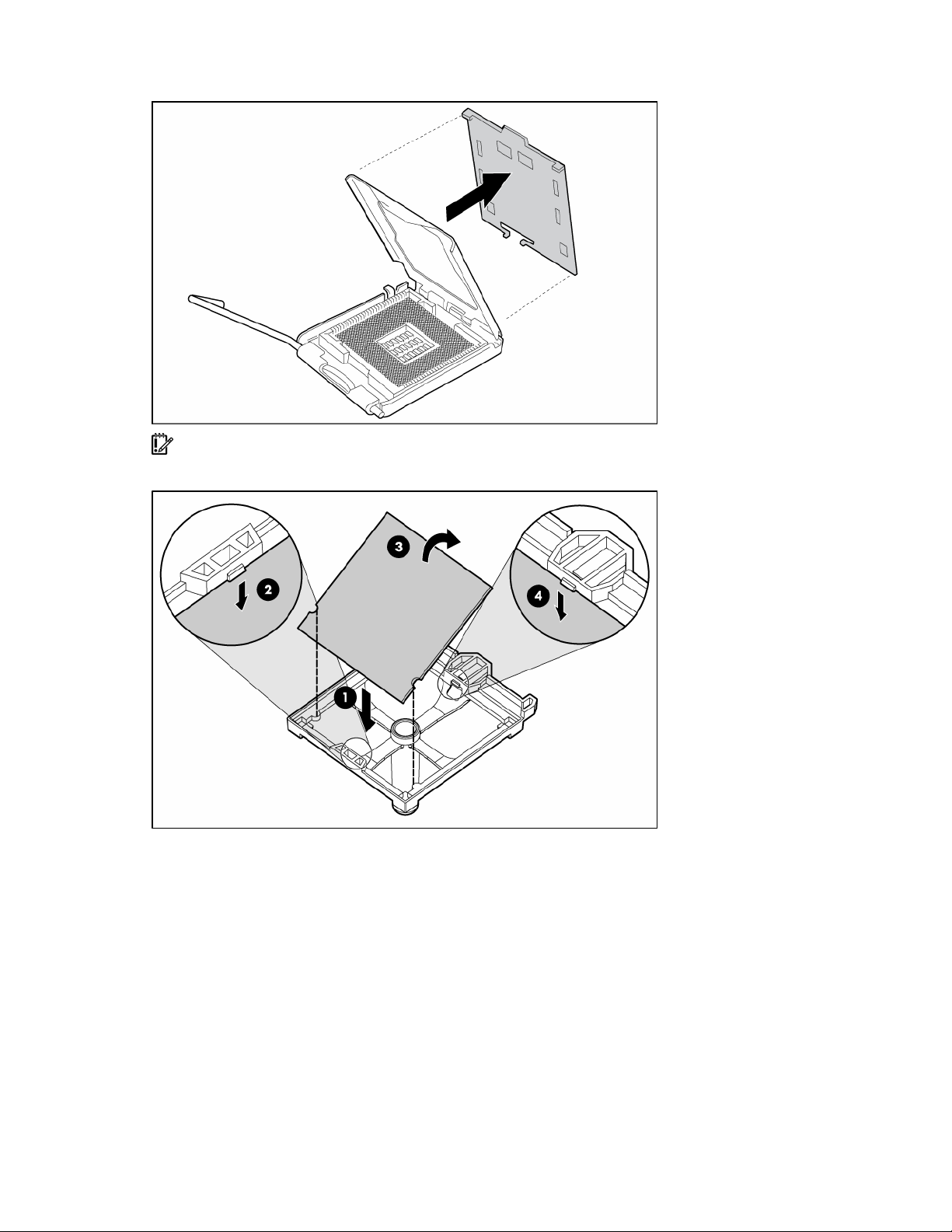
Remove the processor socket protective cover.
6.
IMPORTANT: Be sure the processor remains inside the processor installation tool.
7. If the processor has separated from the installation tool, carefully re-insert the processor in the tool.
Hardware options installation 23
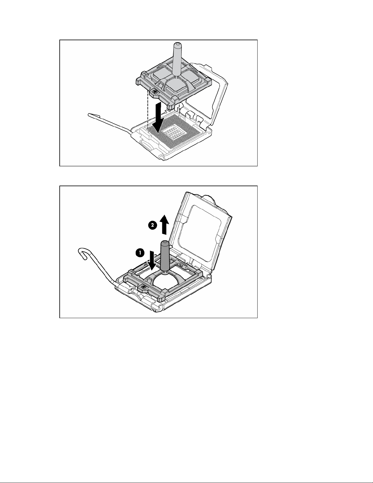
Align the processor installation tool with the socket and install the processor.
8.
9. Press down firmly until the processor installation tool clicks and separates from the processor, and
then remove the processor installation tool.
Hardware options installation 24
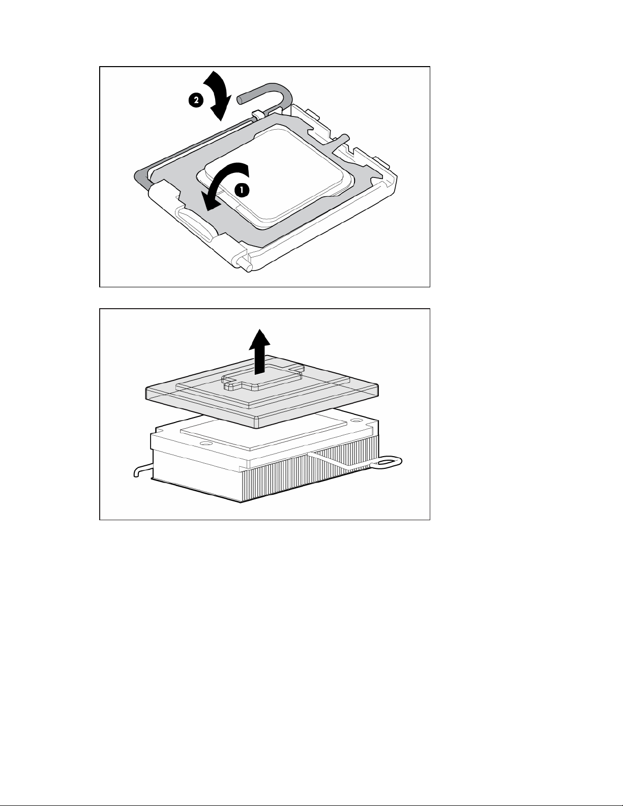
Close the processor socket retaining bracket and the processor retaining latch.
10.
11. Remove the heatsink protective cover.
12. Align the holes in the bottom of the heatsink with the pins in the heatsink retention module.
Hardware options installation 25
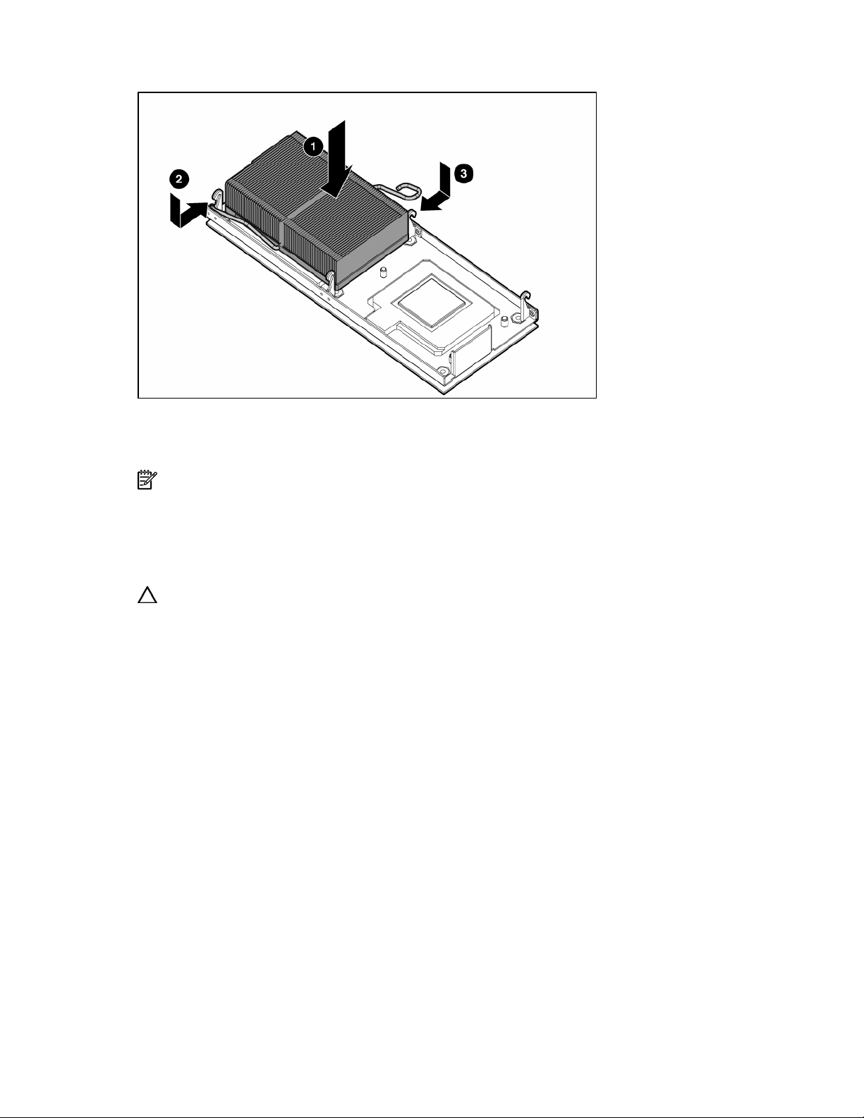
Install the heatsink and close the heatsink retaining latch.
13.
14. Install the access panel (on page 17).
15. Install the server blade ("Installing a server blade" on page 20).
16. Power up the server blade (on page 15).
NOTE: By default, the server blade powers up on installation.
Memory option
The server blade ships with two FBDIMMs installed. The server blade supports up to 32 GB of memory.
FBDIMM guidelines
Single- and dual-rank FBDIMMs
CAUTION: Use only HP FBDIMMs. FBDIMMs from other sources may adversely affect data integrity.
Observe the following FBDIMM installation guidelines:
• All FBDIMMs must be PC-5300 DDR2 667-MHz SDRAM FBDIMMs.
• Both FBDIMM slots in a memory bank must be populated.
• Both FBDIMMs in a memory bank must be identical.
• If mixing dual- and single-rank FBDIMMs, the dual-rank FBDIMMs must be installed in memory bank
1.
PC3200 FBDIMMs can either be single- or dual-rank. While it is not normally important for you to
differentiate between these two types of FBDIMMs, certain FBDIMM configuration requirements are based
on these classifications.
Certain configuration requirements exist with single- and dual-rank FBDIMMs that allow the architecture to
optimize performance. A dual-rank FBDIMM is similar to having two separate FBDIMMs on the same
module. Although only a single FBDIMM module, a dual-rank FBDIMM acts as if it were two separate
FBDIMMs. The purpose of dual-rank FBDIMMs is to provide the largest capacity FBDIMM given the
current FBDIMM technology. If the maximum FBDIMM technology allows for 2-GB single-rank FBDIMMs, a
dual-rank FBDIMM using the same technology would be 4-GB.
Hardware options installation 26
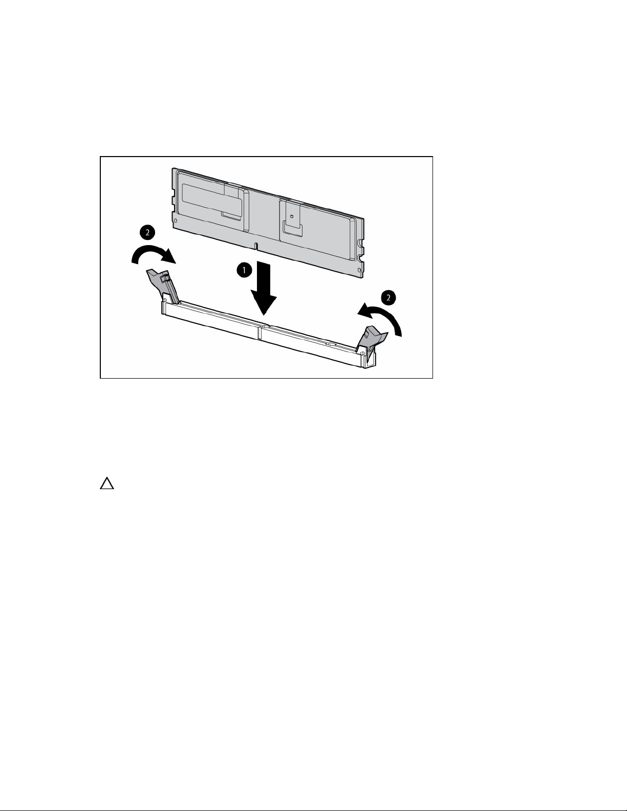
Installing FBDIMMs
1. Power down the server blade (on page 15).
2. Remove the server blade (on page 16).
3. Remove the access panel (on page 16).
4. Open the FBDIMM slot latches.
5. Install the FBDIMM.
To remove FBDIMMs, reverse the installation procedure. For FBDIMM slots 1 and 2, remove the air baffle,
if necessary. Refer to the instructions located on the air baffle.
Hard drive option
The server blade supports up to two hot-plug SFF SAS or SATA drives.
CAUTION: To prevent improper cooling and thermal damage, do not operate the server blade or the
enclosure unless all hard drive and device bays are populated with either a component or a blank.
To install the component:
Hardware options installation 27
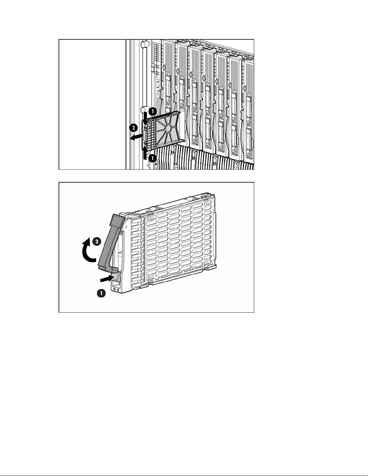
Remove the hard drive blank.
1.
2. Open the release latch and prepare the hard drive for installation.
Hardware options installation 28
 Loading...