

Page 1

White Paper
April 2002
165Z-402B-WWEN
Compaq ProLiant BL e-Class
Prepared by ISSG Mainstream
Marketing Group
Compaq Computer Corporation
Contents
Introduction..................................3
Overview of the ProLiant BL
e-Class System Components .....4
Key Benefits...............................6
Hardware Components ..............7
Software Components..............11
Planning the System
Environment...............................15
Software Deployment...............15
Power Planning........................18
PDU Installation .......................28
Cabling Guidelines...................29
Appendix A: Input Current
and Thermal Dissipation
Calculations ...............................30
Appendix B: Input Power
Budget De-rating .......................31
System Overview and Planning
Abstract: This white paper provides an overview of the ProLiant™
BL e-Class server blades, infrastructure components, and
management tools, as well as provides guidance for establishing a
deployment infrastructure and power planning.
The Compaq ProLiant BL e-Class system is part of the new
generation of ProLiant BL server blades and infrastructure portfolio,
developed for adaptive computing and optimized for rapid
deployment and automated provisioning. Compaq ProLiant
BL e-Class systems are the first power-efficient, ultra-dense edge
server blades engineered for the enterprise. The ProLiant BL e-Class
system delivers industry-leading, power-efficient performance for
front-end applications by integrating an enterprise-class chipset,
ultra-low voltage processor, and other power-saving components in
an ultra-dense design. Up to 280 power-efficient, edge server blades
can fit a standard rack, providing maximum utilization of your data
center space. The ProLiant BL e-Class system also extends your IT
resources through rapid deployment, intelligent management, and
rip-and-replace serviceability. The system enables you to manage
dynamic workloads and reduce idle computing cycles so your
business can quickly and efficiently respond to changing business
needs. An integrated management system and full-compatibility with
the Compaq Insight Manager™ Suite give you maximum virtual
presence and control, management and health monitoring of all your
edge-of-the-network applications.
Page 2

Compaq ProLiant BL e-Class System Overview and Planning 2
Notice
© 2002 Compaq Information Technologies Group, L.P.
Compaq, the Compaq logo, SmartStart, and Compaq Insight Manager are trademarks of Compaq
Information Technologies Group, L.P. in the U.S. and other countries. Microsoft and Windows are
trademarks of Microsoft Corporation in the U.S. and other countries. Intel and Pentium are trademarks of
Intel Corporation in the U.S. and other countries. All other product names mentioned herein may be
trademarks of their respective companies.
Compaq shall not be liable for technical or editorial errors or omissions contained herein. The information
in this document is provided “as is” without warranty of any kind and is subject to change without notice.
The warranties for Compaq products are set forth in the express limited warranty statements accompanying
such products. Nothing herein should be construed as constituting an additional warranty.
Page 3

Compaq ProLiant BL e-Class System Overview and Planning 3
Introduction
The purpose of this white paper is to give an overview of the Compaq ProLiant BL e-Class
system: the first power-efficient, ultra-dense edge server blades engineered for the enterprise. The
paper is divided into two sections:
Overview of the system components
Planning the system environment
Note: The ProLiant BL line also contains the ProLiant BL p-Class system architecture.
However, this paper will focus on the ProLiant BL e-Class system architecture only. For
information regarding the ProLiant BL p-Class system architecture please see the ProLiant
BL p-Class System Overview and Planning white paper.
The build-out of Internet infrastructure and the trend to scale out within the data center have
created the need for businesses to deploy greater numbers of servers, particularly for edge-of-thenetwork applications such as Web serving, media streaming, load balancing, caching, and firewall
protection. However, adding servers increases operating costs, requires more power and space,
and makes system administration more complex. As a result, requirements for IT staffing, floor
space, and power are exceeding available resources.
Compaq has addressed these trends by developing a complete portfolio of modular, blade servers:
the new ProLiant BL Line. The ProLiant BL Line is specifically designed to address the needs of
space-constrained enterprises and service providers for increased server density, rapid
deployment and provisioning, and remote manageability.
ProLiant BL servers are optimized for use with the Compaq Rapid Deployment Pack enabling
automatic configuration and installation of operating systems and applications on tens or
hundreds of servers simultaneously. ProLiant BL server blades include Compaq industry-leading
technologies such as tool-free mechanical designs, hot-plug redundant components, and
integrated management functionality.
The ProLiant BL architecture is designed to protect customer investments in two important ways:
Providing longevity of the ProLiant BL server blade and interconnect infrastructure
Enabling installation of ProLiant BL server blades in standard racks along with legacy servers
and storage
Compaq designed the ProLiant BL line specifically for customers operating in a multi-tiered
environment requiring everything from power-efficient, front-end to high-performance SMP
blades. Compaq ProLiant DL and ProLiant ML servers offer a wide range of industry-standard
solutions to meet customer needs. ProLiant BL servers are therefore not a replacement for
ProLiant DL and ProLiant ML server solutions, but a complementary addition to the ProLiant
product family, targeted at specific customer needs.
Page 4
Compaq ProLiant BL e-Class System Overview and Planning 4
(20)
plug
p
)
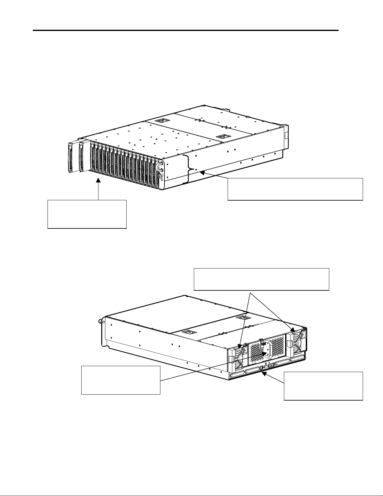
Overview of the ProLiant BL e-Class System Components
ProLiant BL e-Class
server blade enclosure
ProLiant BL10e
power-efficient edge
server blades
Figure 1. ProLiant BL e-Class server blade enclosure (front view) with 20 ProLiant BL10e server
blades
Two (1 + 1) redundant, hot-plug
power supplies
Fan cage with four
(2 + 2) redundant,
hot-
Figure 2. ProLiant BL e-Class server blade enclosure (rear view) with two redundant, hot-plug power
supplies, fan cage with 4 redundant, hot-plug fans, and RJ-21 Patch Panel
fans
RJ-21 Patch Panel
(interconnect tray
tion
o
Page 5

Compaq ProLiant BL e-Class System Overview and Planning 5
The ProLiant BL e-Class system is comprised of several different components. The following
table provides the required component categories.
In order to design a successful configuration, at least one component from each category is
Note:
required.
Table 1. ProLiant BL e-Class System Required Components
Required Component
Categories
ProLiant BL10e powerefficient edge server blade
ProLiant BL e-Class server
blade enclosure
Interconnect trays (three
options)
Function Options
Each ProLiant BL10e server blade features a single
Ultra-Low Voltage Intel Pentium III processor
(Tualatin-based) with 512-K cache operating at
700 MHz, 2 DIMM slots for up to 1 GB max
ECC memory, one 30-GB non-hot-plug ATA hard drive,
and two 10/100 NICs.
Each rack-mountable ProLiant BL e-Class server blade
enclosure is 3U high and holds up to 20 ProLiant BL10e
server blades. The enclosure contains dual, 1 + 1
redundant 600-Watt hot-plug power supplies and four
2 + 2 redundant hot-plug fans. Server blades plug into
the server blade enclosures for network and power
connections.
Each ProLiant BL e-Class server blade enclosure
requires an interconnect tray. The interconnect tray
routes the network connections from the server blades
out the back of the enclosure. There are three different
interconnect tray configurations for network cable
management.
Server blades will be sold in
singles and in 10-packs.
ProLiant BL e-Class RJ-45
Patch Panel (with forty RJ-45
connectors)
-or-
ProLiant BL e-Class RJ-21
Patch Panel (with four RJ-21
connectors)
- or -
ProLiant BL e-Class C-GbE
Interconnect Switch (with four
Gigabit Ethernet uplink
connectors): reduces network
cables per enclosure from
forty to as few as one
(Available Spring 2002)
Page 6

Compaq ProLiant BL e-Class System Overview and Planning 6
Key Benefits
Rapid deployment/redeployment to save valuable time
• Takes only seconds to snap in server blades and power supplies once the rack
infrastructure is in place
• Single-sided access to most pluggable components
Using the Compaq ProLiant Essentials Rapid Deployment Pack software
• Provision one or hundreds of server blades in minutes
• Pre-configure server blade bays so new server blades will automatically be configured
when plugged in
Integrated Administrator server blade management system
• Enables serial and network access to the enclosure and all server blades via a single IP
address
• Provides health monitoring and alerts
• Customizable security features
Redundant features to provide high availability at the front end
• Dual, 1 + 1 redundant hot-plug power supplies for power redundancy across all server
blades in an enclosure
• Redundant NIC capability
• Four 2 + 2 redundant hot-plug fans across all server blades in an enclosure
• Server blade redundant ROM
Relieves cabling problems
• Access all 40 server blade NICs via as few as a single Gigabit Ethernet uplink using the
ProLiant BL e-Class C-GbE Interconnect Switch option (Available Spring 2002)
• Designed for headless management, no keyboard, video, and mouse cables
Increased density saves valuable floor space
• Up to 280 single-processor ProLiant BL10e server blades fit into a 42U rack.
• Density is increased without sacrificing performance for front-end applications such as
web serving.
• This configuration meets your changing capacity needs quickly and easily.
Add or remove additional server blades or power supplies from the rack without powering down
the system
Page 7
Compaq ProLiant BL e-Class System Overview and Planning 7
• Server blades are designed for remote management from anywhere in the world, so there
is no need to have experts physically located in the data center.
• Ease of deployment/redeployment and enhanced management features means fewer
people are needed to manage a large number of blades.
Designed to Protect Your Investment
• Fits into Compaq, third-party, and Telco racks
• Mixes with traditional servers and storage
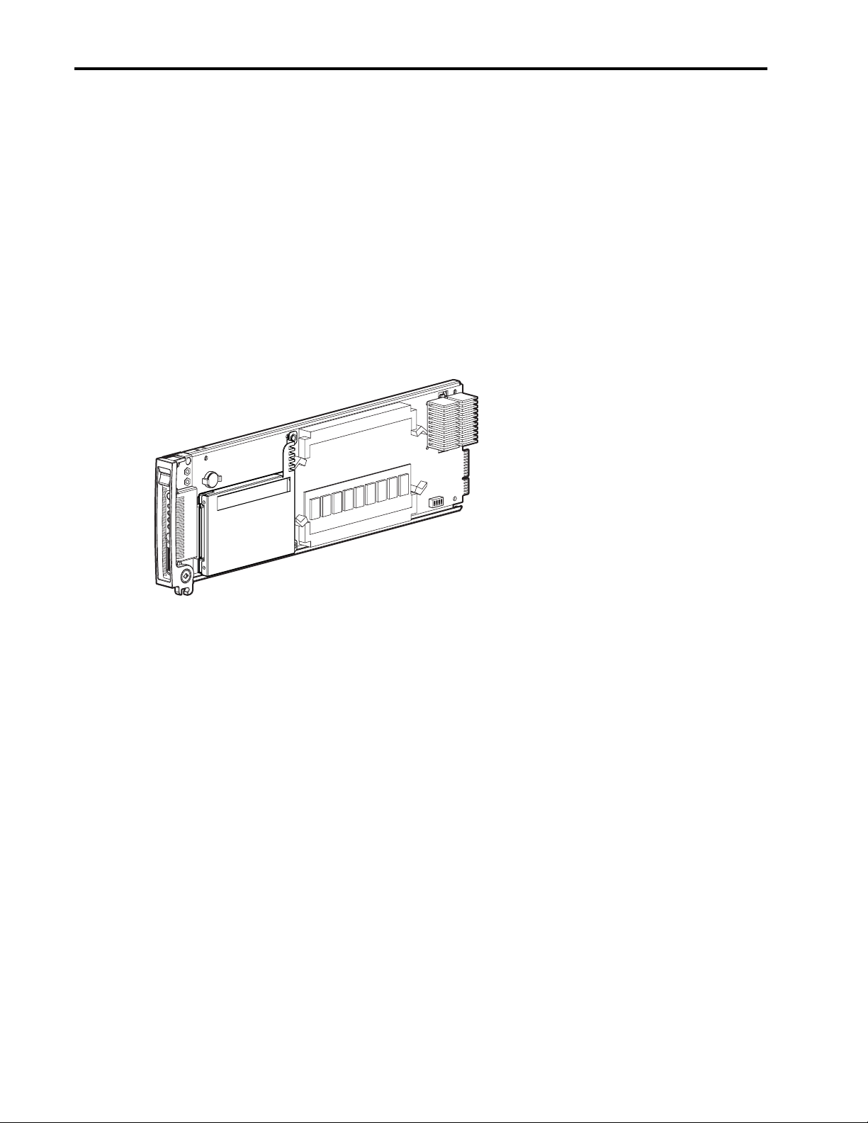
Hardware Components
ProLiant BL10e Server Blade
Figure 2. ProLiant BL10e single-processor server blade
Description
The ProLiant BL10e server blade (Figure 2) is ideal for use as a power efficient, front-edge server
and for utility applications (such as Web hosting, computational clusters, terminal server farms,
and domain controllers). By removing the CD-ROM/diskette drive, PCI slots, and the power
subsystem, Compaq has created the densest ProLiant server ever. Up to 280 ProLiant BL10e
server blades fit a standard 42U rack.
The power efficient front-edge server blades fit within the 3U ProLiant BL e-Class server blade
enclosure. The enclosure contains twenty server blade bays, dual-redundant hot-plug power
supplies, redundant hot-plug fans, and an interconnect tray bay that is used to house one of three
interconnect tray options.
Features
Processor: One Ultra-Low Voltage Intel Pentium III processor (Tualatin-based) with 512K cache
operating at 700 MHz
System Bus: 100-MHz
Chipset: ServerWorks LELP 3.0 chipset
Hard drive: One 30-GB non-hot-plug ATA disk drive, 4200 rpm, 2.5"
Page 8

Compaq ProLiant BL e-Class System Overview and Planning 8
Memory: Two DIMM slots with a maximum capacity of 1 GB of 133-MHz, ECC SDRAM
(operating at system bus speed of 100-MHz)
Management: The ProLiant BL e-Class Integrated Administrator (“Integrated Administrator”) is
a centralized management and monitoring system for the ProLiant BL e-Class enclosure and
server blades. The Integrated Administrator acts as a combination terminal server and remote
power controller, enabling out-of-band, secure, serial console connections to all server blades in
the enclosure.
NICs: Each server blade has two Preboot eXecutable Environment (PXE) capable Compaq
NC3163 Fast Ethernet NICs embedded 10/100 WOL (Wake On LAN).
LEDs on each Server Blade
• Unit Identification LED (“UID”) and button. UID is a blue LED on the front of each
server blade and enclosure and can be activated locally or remotely to help a user onsite
find a specific server blade immediately in a densely loaded rack.
• Health
• NIC link and activity (2)
• Disk drive activity
• Power
Local I/O: Keyboard, video, mouse, USB, and serial connections are available for each server
blade by attaching the Diagnostic Adapter (provided with each server blade enclosure).
Density: Up to 280 server blades fit into a 42U rack.
Supported Operating Systems: The ProLiant BL line supports the most current versions of these
top-tier operating systems: Microsoft Windows 2000 Server, Microsoft Windows .NET Server
(when it becomes available in 2002), Red Hat Linux, SuSE Linux, and Caldera Linux.
Page 9
Compaq ProLiant BL e-Class System Overview and Planning 9
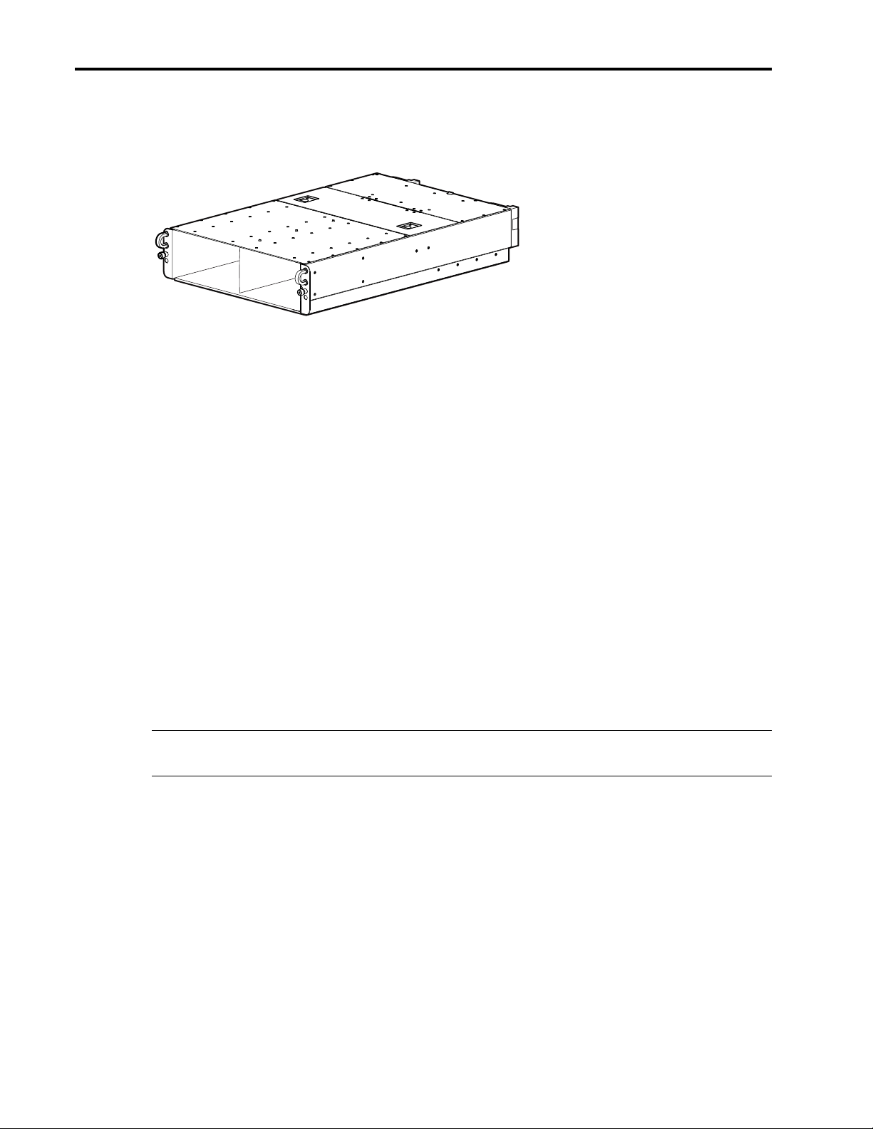
ProLiant BL e-Class Server Blade Enclosure
Figure 3. ProLiant BL e-Class server blade enclosure
Description
ProLiant BL10e server blades are housed in a 3U server blade enclosure (Figure 3). The server
blades plug into the enclosure for power and network connections.
Each ProLiant BL e-Class server blade enclosure has twenty (20) server blade bays in the front
and an interconnect tray bay in the back (for one of three interconnect tray options). Up to
fourteen server blade enclosures can fit in a 42U rack.
Features
Dimensions: 3U height, standard 48-cm (19-inch) width, and 73.30-cm (28.86-inch) depth
Toolless installation: Server blade enclosures are easily installed with spring-loaded rack rails
and thumbscrews.
Management: See description below in “Software Components” of the Integrated Administrator.
Power redundancy: Dual 1 + 1 redundant 600-Watt, hot-plug power supplies
Cooling redundancy: Four 2 + 2 redundant hot-plug fans
rd
Rack requirements: The server blade enclosure fits in Compaq, Telco, and 3
-party standard
racks.
Note: An optional Telco Rack Mounting Hardware option kit is required for installing ProLiant
BL e-Class systems in a Telco (or 2-pole) rack.
ProLiant BL e-Class Interconnect Trays
Description
Each ProLiant BL e-Class server blade enclosure requires an interconnect tray. The interconnect
tray plugs into the rear of the server blade enclosure and is used to route network connections
from the server blades out the back of the enclosure. Each interconnect tray includes the
Integrated Administrator module for centralized server blade and enclosure monitoring and
management (see “Software Components” for more detail).
Page 10
Compaq ProLiant BL e-Class System Overview and Planning 10
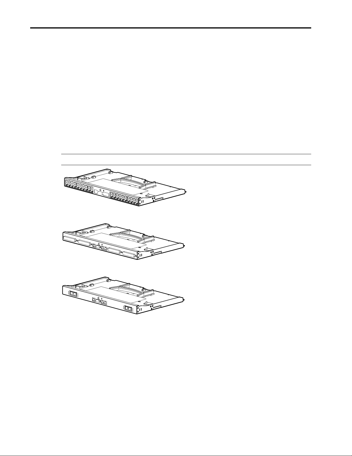
There are three interconnect tray options:
ProLiant BL e-Class RJ-45 Patch Panel: The RJ-45 patch panel functions as an Ethernet passthrough only and has forty RJ-45 connectors. It brings all server blade NIC signals out as separate
RJ-45 connectors. See Figure 4.
ProLiant BL e-Class RJ-21 Patch Panel: The RJ-21 patch panel functions as an Ethernet passthrough only. It brings all server blade NIC signals out via four separate RJ-21 connectors. See
Figure 5.
ProLiant BL e-Class C-GbE Interconnect Switch (Available Spring 2002): The Interconnect
Switch is designed to dramatically reduce the number of network cables attached to the rear of the
server blade enclosure and offers advanced switching features, including VLAN capability. The
interconnect switch reduces up to forty server blade network connections to as few as a single
Gigabit Ethernet uplink connector. See Figure 6.
Note: The interconnect switch is not meant to replace customers’ core network switches.
Figure 4. ProLiant BL e-Class RJ-45 Patch Panel
Figure 5. ProLiant BL e-Class RJ-21 Patch Panel
Figure 6 ProLiant BL e-Class C-GbE Interconnect switch
Features
Reduced Cabling: The ProLiant BL e-Class C-GbE Interconnect Switch reduces forty 10/100
connectors to four 10/100/1000 uplink connectors. The customer is not required to use all uplink
connectors and may use and configure one or more uplink connectors as desired, providing up to
a 40-to-1 reduction in the number of network cables for each server blade enclosure.
Page 11

Compaq ProLiant BL e-Class System Overview and Planning 11
Integrated high-availability features
• Two separate redundant interconnect switch modules per enclosure
• Redundant data paths to and from each interconnect switch module to each server blade
• Redundant data path cross connections between the two interconnect switch modules
• Two pairs of redundant Gigabit uplink connectors per each interconnect switch module
• Spanning tree protocol support to provide loop-free path redundancy
Pre-configured: The Interconnect Switch is completely pre-configured for immediate use with
the ProLiant BL e-Class system. It plugs directly into the back of the ProLiant BL e-Class server
blade enclosure and does not occupy a server blade bay or use any additional rack space.
Industry-Standard design: The Interconnect Switch is industry-standard and does not use
proprietary protocols. It is compatible with industry-standard switches, such as those from Cisco
and 3Com. Additionally, an industry-standard command line interface is planned for a free 2H02
software update release.
Low Wattage: The Interconnect Switch has been designed for low power usage (maximum 60
watts per Interconnect Switch).
Software Components
Compaq ProLiant BL e-Class Integrated Administrator
The ProLiant BL e-Class Integrated Administrator is a centralized management and monitoring
system specifically designed for the ProLiant BL e-Class enclosure and server blades. The
Integrated Administrator acts as a combination terminal server and remote power controller,
enabling out-of-band, secure, serial text console connections to all server blades in the enclosure,
and offers all of the following:
Full command line and web interfaces
• Server blade privileges can be set on a per-user basis
• Virtual power button remotely powers on or off server blades and the enclosure
• Virtual NMI button generates non-maskable interrupt for crash debug and analysis
• More than 100 scriptable commands enable automated management
Remote administration
• Enables access to server blade’s serial console
• Enables full control over server blade's Power-On Self Test (POST) and boot process,
including the ROM-Based Setup Utility (RBSU)
• Enables future manageability enhancements with the Online Integrated Administrator
Firmware Update feature
Hardware health monitoring
• Monitors and controls the enclosure fans, temperature sensors, power supplies, and server
blade status
Page 12

Compaq ProLiant BL e-Class System Overview and Planning 12
Offline console buffering (when not connected) and event logging
• Operating system console logging
• Server blade and enclosure hardware events
Security features
• Secure Shell access
• User administration for up to 25 users
• Event generation for invalid login attempts
• Logging of user actions in event log
• Selective enabling of all protocols, such as Telnet
• Out-of-band management using Integrated Administrator’s RS-232 console
• SSL (web interface)
• Customer installable SSL certificates
Increased availability
• The Integrated Administrator is a self-contained embedded system with its own
processor, memory, NIC, and Flash ROM.
• The enclosure itself is intelligent and fault-tolerant, and continues to function
independently of the Integrated Administrator.
• The Integrated Administrator enables online firmware update with code signing to ensure
only certified software releases are installed.
Compaq Insight Manager 7 integration
• Compaq Insight Manager™7 identifies the Integrated Administrator as a server blade
“management processor.”
• The Integrated Administrator status is part of the server blade status. If the Integrated
Administrator is degraded, all server blades managed by that Integrated Administrator are
shown as degraded.
• Compaq Insight Manager 7 can capture the Integrated Administrator SNMP traps.
• Compaq Insight Manager 7 and web agents enable the user to launch the Integrated
Administrator web interface.
The Integrated Administrator web interface enables full access and control of the server blades
and enclosure via a browser, including:
Enclosure management
• Monitor fans, power supplies, and temperature
• Graceful enclosure and server blade power shutdown
• Enclosure UID control
Server Blade management
• Virtual power and UID buttons
Page 13

Compaq ProLiant BL e-Class System Overview and Planning 13
• Remote serial console
• General health status
• User management
• Add/delete/modify administrators/groups/users
• Server blades are assigned to groups
• Two levels of user access to groups
For more information about the ProLiant BL e-Class Integrated Administrator, please visit
the Compaq website:
http://www.compaq.com/products/servers/proliant-bl/e-class/integrated-admin.html
Compaq ProLiant Essentials Rapid Deployment Pack
Compaq ProLiant Essentials Rapid Deployment Pack provides a remote console-based method
for scalable, automated server deployment without network degradation. Using Rapid
Deployment Pack, IT administrators can deploy from one to hundreds of server blades in a
fraction of the time it typically takes.
The deployment console’s graphical interface provides intuitive drag-and-drop events, such as
scripts and images, to deploy the operating systems and applications on any combination of
server blades and then simultaneously deploy multiple server blades. Rapid Deployment Pack
also has advanced features that can detect and display server blades based on their physical rack,
enclosure, and bay locations. You can set the deployment console to automatically install
pre-defined configurations on newly installed server blades.
Rapid Deployment Pack also improves uptime by facilitating a rip-and-replace service model. An
administrator can use Rapid Deployment Pack to pre-assign a particular configuration to each
server blade bay in an enclosure. When a server blade is installed into a pre-configured bay, the
deployment server immediately installs the configuration onto the newly-installed server blade
without local intervention. This feature significantly reduces the time and effort needed to keep
servers in production.
Use of Rapid Deployment Pack maximizes customers’ IT resources by providing a full server
build from a remote console for initial power on, automated server configuration on the fly, and
installation of standard software sets across systems. The intuitive interface reduces the level of
IT skill sets needed to deploy and re-deploy ProLiant BL server blades in the data center and
throughout the network.
Refer to the next section “Planning the System Environment” for information about setting up a
deployment infrastructure using Rapid Deployment Pack. For information on Rapid Deployment
Pack, refer to the ProLiant Integration Module for Altiris eXpress User Guide on either the Rapid
Deployment Pack CD or the Compaq website:
http://www.compaq.com/manage/rapiddeploy
Compaq Insight Manager 7
Compaq Insight Manager 7 is the next-generation Web-based enterprise management console
targeted for availability in late 2001 from Compaq. Like Compaq Insight Manager XE, Insight
Manager 7 brings together in one location all fault, performance, and management information
Page 14

Compaq ProLiant BL e-Class System Overview and Planning 14
about the IT infrastructure. By integrating current enterprise management technology with the
latest advances in web technology, it enables IT administrators to monitor and manage groups of
servers, clients, clusters, and networking products from a standard Web browser. Insight
Manager 7 is capable of discovering and managing devices from Compaq and other vendors
using SNMP, DMI, and HTTP. It logs alerts from these devices, and it sends email or pager
notifications of alerts to the appropriate person based on the assigned roles and responsibilities of
the IT staff.
For more information about the Compaq Insight Manager 7, please visit the Compaq website:
http://www.compaq.com/products/servers/management/cim7-description.html
Page 15

Compaq ProLiant BL e-Class System Overview and Planning 15
Planning the System Environment
Software Deployment
The new ProLiant BL10e server blades are designed for headless management and deployment.
While there are many possibilities for deploying the operating system of choice on ProLiant
BL10e server blades, the following methods have been tested and are supported by Compaq:
Compaq ProLiant Essentials Rapid Deployment Pack
SmartStart Scripting Toolkit
OS installation via devices connected to the diagnostic adapter
Pre-eXecution Environment (PXE)
Important: When you install the Compaq ProLiant BL e-Class system to your network, the
server blades automatically boot to the network using PXE.
Before you install server blades in the ProLiant BL e-Class server blade enclosure, be sure the
Rapid Deployment Pack, which contains PXE, is installed and running on your network.
Without a PXE server, such as Rapid Deployment Pack, running on the network, a server blade
stops at the following prompt:
“Non-System disk or disk error. Replace and strike any key when ready.”
Compaq ProLiant Essentials Rapid Deployment Pack
Rapid Deployment Pack includes the Altiris eXpress Deployment Server software as well as the
ProLiant Integration Module. The ProLiant Integration Module includes the pre-configured
scripts to install Windows 2000 Server Edition and Red Hat Linux 7.2, as well as Compaq
value-add software (such as CSP and agents).
Note: If using PXE to do remote deployments with Rapid Deployment Pack, a DHCP server is
required.
Licensing for the Rapid Deployment Pack is on a per-server basis; however, Rapid Deployment
Pack can also be obtained at a promotional price bundled with a ProLiant BL e-Class server blade
enclosure (Available Spring 2002).
For information on Rapid Deployment Pack, refer to the ProLiant Integration Module for Altiris
eXpress User Guide on either the Rapid Deployment Pack CD or the Compaq website:
www.compaq.com\manage\rapiddeploy
http://
When using the Rapid Deployment Pack to deploy Linux, you will also need an NFS server to
install Red Hat Linux 7.2. The NFS server must be running Red Hat Linux 7.2 and should have
at least 2 GB free disk space on the /usr filesystem. An NFS setup script must be run on the NFS
server, directions are included on the RDP CD. To obtain additional information about Rapid
Deployment Pack, or to purchase licenses for installation, go to the Compaq website:
http://www.compaq.com/manage/rapiddeploy.html
Page 16

Compaq ProLiant BL e-Class System Overview and Planning 16
SmartStart Scripting Toolkit
The SmartStart Scripting Toolkit is a server deployment product that delivers a hands-off,
unattended installation for high-volume ProLiant server deployments. The Scripting Toolkit
provides a flexible method for creating standard server configuration scripts that are used to
automate the server configuration process. The Scripting Toolkit saves time from each server
deployed, making it possible to scale server deployments to high volumes in rapid fashion.
The SmartStart Scripting Toolkit contains customizable pre-configured scripts for unattended OS
deployment. The Scripting Toolkit requires the user to create a custom boot CD or boot diskette
to start the OS installation on ProLiant BL10e server blades. Booting from local CD or diskette
requires connecting a USB device to the diagnostic adapter (see ProLiant BL e-Class system
documentation). To obtain additional information about the Scripting Toolkit (including sample
scripts), download the utility and readme files from the Compaq website:
http://www.compaq.com/smartstart.html.
Note: This method can be used to deploy any Linux OS distribution that supports an unattended
installation, but Compaq only supports and provides sample scripts for Red Hat Linux versions
supported by the ProLiant BL line of server blades.
USB Diskette or USB CD-ROM (connected to the Diagnostic Adapter for ProLiant BL10e server blades)
The diagnostic adapter, which connects to the front of the server blade, contains PS/2, USB,
serial, and video connections. These ports enable connecting a PS/2 keyboard, PS/2 mouse, USB
diskette, and USB CD-ROM. A USB-diskette or USB CD-ROM can be connected to the
diagnostic adapter for OS installation, but depends on USB support by the OS vendor. A USB
diskette drive can be used to complete a network installation booting from a USB diskette, or to
use the SmartStart Scripting Toolkit (described above). For specific information on USB
supported on Compaq ProLiant servers, please visit the Compaq website:
http://www.compaq.com/products/servers/platforms/usb-support.html
Additionally, review the product QuickSpecs for a full list of USB devices Compaq has tested
and supports.
Windows 2000 Deployment
The Microsoft Windows 2000 operating system claims support for OS installation with only
certain USB CD-ROM drives. Contact Microsoft for a listing of OS-supported USB devices.
Linux Deployment
Red Hat Linux 7.2 supports installation via a USB CD-ROM, but only for OS vendor-supported
USB devices. Contact Red Hat (or the OS vendor) for a listing of supported devices. Review the
product QuickSpecs to review the USB devices Compaq has tested and supports. For details on
how to install the Linux operating system using the diagnostic adapter on ProLiant BL10e server
blades, please visit the Compaq website:
http://www.compaq.com/products/servers/Linux/compaq-howto.html
Page 17

Compaq ProLiant BL e-Class System Overview and Planning 17
Preboot eXecution Environment (PXE)
PXE can be used to deploy the operating system on any server. For information on PXE
requirements and how to setup a PXE server, view the whitepaper at the Compaq website:
http://www.compaq.com/products/servers/linux/redhat-whitepapers.html
Windows 2000 Deployment
Microsoft Windows 2000 has an additional component called Remote Installation Services (RIS),
which can be used to setup images of Windows 2000 Professional for deployment. However,
Microsoft does not provide a method for installing Windows 2000 Server-based operating system
editions. To install Windows 2000 Server Edition on ProLiant BL10e server blades, a PXE
deployment server (such as Altiris eXpress Deployment Server) is required.
Linux Deployment
Red Hat Linux, as well as other distributions, supports the installation of a PXE deployment
server to install the OS on a ProLiant BL10e. For detailed instructions on how to set up a PXE
deployment server and deploy Red Hat Linux 7.2, please visit the Compaq website:
http://www.compaq.com/products/servers/linux/redhat-whitepapers.html
Troubleshooting
For troubleshooting information regarding the Rapid Deployment Pack, download the user guide
at the Compaq website:
http://www.compaq.com/manage/rapiddeploy.html
Although USB devices are supported, the SmartStart CD does not support booting via a USB
CD-ROM for operating system installation.
The Microsoft Windows 2000 OS CD has an option to create boot diskettes to start the OS
installation. These diskettes can be booted using a USB diskette drive connected to the diagnostic
adapter, but the OS installation fails when it tries to connect to the CD if a USB CD-ROM device
is used. The installation path from boot diskettes is therefore not supported.
A USB diskette cannot be connected to the diagnostic adapter to provide an updated storage
driver during the F6 prompt of the Windows 2000 installation.
For troubleshooting information regarding Compaq-specific problems installing Linux, go to the
Compaq website:
http://www.compaq.com/products/servers/Linux/compaq-howto.html
For general questions regarding Linux support on Compaq ProLiant servers, go to the Compaq
website:
http://www.compaq.com/products/servers/linux/
Linux whitepapers can be found at the following URL:
http://www.compaq.com/products/servers/linux/redhat-whitepapers.html
Page 18

Compaq ProLiant BL e-Class System Overview and Planning 18
Power Planning
The following general guidelines should be followed when planning and installing a ProLiant
BL e-Class system:
High-voltage deployment is highly recommended (200-240VAC) because of lower current
requirements.
Both power supplies provided with your ProLiant BL e-Class server blade enclosure should be
plugged into an AC power source to assure full power supply redundancy.
Avoid single points of failure:
• Do not cable both enclosure power supplies to the same PDU (or power strip) to prevent
a single PDU failure causing loss of the enclosure.
• Do not cable multiple enclosures or PDUs to the same AC wall outlet (or AC breaker) to
prevent a single AC source failure causing loss of all enclosures.
• Each power supply should be supplied by different AC sources – ideally, different
municipal AC power networks
The ProLiant BL e-Class server blade enclosure’s two power supplies share the load
approximately 50/50%, but this can vary by ± 12% up to 44/56%. For example, a 1000 W load
could be shared 440/560 W.
Determine how many PDUs you need. For instance, a 16-A, low-voltage PDU can only meet the
requirements of one fully loaded, non-AC-redundant enclosure at 10 A. A 24-A high-voltage
PDU can support up to 4 fully loaded, non-AC-redundant enclosures at 4*5 = 20 A.
Decide what level of redundancy your environment needs (described in section “Redundancy and
Single Sources of Failure”). This requires a significantly different PDU configuration.
• Power supply redundancy (standard on ProLiant BL e-Class server blade enclosures)
• PDU redundancy
• AC source redundancy
Carefully review PDU or power strip current limitations to avoid the “domino effect” (described
below). If a power supply or AC source fails (or is unplugged), the remaining components must
have enough capacity to support the new power distribution.
The ProLiant BL e-Class server blade enclosure should always have two power supplies installed
to ensure proper airflow and adequate cooling. This is true even if only one power supply has AC
power.
ProLiant BL e-Class Enclosure Power Specification Summary
There is a 1000-W AC input for a fully loaded ProLiant BL e-Class server blade enclosure.
There is a 10-A maximum current draw at low voltage (100 V).
There is a 5-A maximum current draw at high voltage (200 V).
The enclosure supports power supply redundancy with 2 power supplies in a 1 + 1 configuration.
Page 19

Compaq ProLiant BL e-Class System Overview and Planning 19
Definitions and Theory
Single Sources of Failure (SSOF)
A server blade enclosure (or rack) can fail if it is dependent on a critical component or resource
that is itself vulnerable to failure. This dependence is deemed a single source of failure.
Redundancy is based on the types of failures a configuration can tolerate and is characterized by
removal of as many single sources of failure as possible. This section describes typical single
sources of failure and the redundancy features needed to survive their failure. These single
sources of failure include power supplies, power cords, PDUs, and AC sources.
Power Supply Failure
The power supply may have an internal failure. This term also loosely applies when the supply’s
power cord is unplugged, the supply has an AC source failure, and when the power supply is not
fully inserted into the server blade enclosure.
Power Supply Redundancy
Power supply redundancy is a feature enabling an enclosure to survive the failure of a power
supply. A 1 + 1 redundant enclosure can tolerate a single power supply failure by re-distributing
100% of the load to the remaining power supply.
Figure 7. Power supply redundancy, single source of failure = PDU and AC source
Figure 7 shows an enclosure that can survive a power supply failure or unplugged power cord.
The ProLiant BL e-Class server blade enclosure has power supply redundancy built in, provided
you have two working power supplies, two attached power cords, and stable AC source(s).
Note: The Power Distribution Unit (PDU), PDU power cord, and AC source are each single
sources of failure. Power supply redundancy implies the AC source or PDU supporting the
remaining power supply has sufficient capacity to handle the re-distributed load.
Page 20

Compaq ProLiant BL e-Class System Overview and Planning 20
PDU
A PDU has one or two AC power inlets and multiple power outlets (12) to simplify power cord
management.
PDU Failure
The PDU may have an internal failure or its input circuit breaker may be tripped due to
over-current. A PDU single source of failure can also loosely be described as a situation
when the PDUs have tripped due to over-current. This term also loosely describes when
the PDU’s power cord is removed or the AC source supplying power to the PDU fails.
PDU Redundancy
A PDU configuration that enables a server blade enclosure (or rack of enclosures) to
survive a PDU failure by re-distributing the load to other PDUs provides PDU
redundancy.
Figure 8. PDU redundancy, single source of failure = AC source
Figure 8 shows an enclosure that can survive a power supply failure, PDU failure, or unplugged
PDU power cord.
Note: The AC source is single source of failure.
PDU redundancy implies the remaining PDU(s) and AC sources have sufficient capacity to safely
handle the re-distributed load.
Page 21

Compaq ProLiant BL e-Class System Overview and Planning 21
AC Source
An AC source is AC power delivered via an AC wall outlet, main circuit breaker or a building’s
power infrastructure. This term also loosely describes AC power delivered to a power supply or
PDU.
AC Source Failure
The AC source supplying power to a component has failed.
AC Source Redundancy
An AC source redundancy is a power configuration that enables an enclosure (or rack of
enclosures) to survive the failure of an AC source by re-distributing the load to an
alternate AC source.
Figure 9. AC source full redundancy
Figure 9 shows a configuration that can survive a power supply failure, PDU failure, and even a
single AC source failure.
Note: AC source redundancy implies the remaining AC source and PDU(s) have sufficient
capacity to safely handle the re-distributed power load.
Figure 10. Dual AC PDU and power supply redundancy, single source of failure = PDU
Figure 10 shows a dual-AC PDU configuration that can survive a power supply failure, and even
a single AC source failure.
Note: The dual-AC PDU is still a potential single source of failure.
Page 22

Compaq ProLiant BL e-Class System Overview and Planning 22
The Domino Effect
If a power supply, PDU, or AC source fails or is unplugged, the power load is automatically
re-distributed. The remaining AC source and PDUs must support 100% of enclosure power
requirements. If the resulting load exceeds the capacity of the remaining PDU, that PDU’s circuit
breaker may trip, resulting in a potential “domino effect”.
Similarly, if the resulting load exceeds the capacity of the remaining AC source, that AC source
may also fail.
Example
Figure 11 shows four fully loaded enclosures using two low-line voltage (100-120VAC) PDUs
(P/N 207590-D71). The configuration is not PDU redundant, but it appears to be power-supply
redundant. In reality, this configuration is susceptible to the domino effect if even a single power
supply fails.
Figure 11. Domino effect caused by low-line current overload
Normal Operation
At low-line, each fully loaded enclosure draws 10 A that are shared approximately 50/50%
between the enclosure’s two power supplies. The output circuit breaker on each PDU supports
5A, which is within the breakers’ 15 A limit. The PDU supports 4 * 5 = 20 A total which is also
within the breakers’ input limit of 24 A.
Failure scenario 1
If a single power supply fails or is unplugged (for example, power supply 2 in
enclosure 4), PDU 1 trips, followed quickly by PDU 2. This chain reaction occurs after
power supply 1 fails because PDU 1 must now support the full 10-A load of enclosure 4.
This is within PDU 1’s output circuit breaker limit of 15 A. However, PDU1’s total
output current becomes 5 + 5 + 5 + 10 = 25 A, which exceeds PDU 1’s input rating of 24
A. By exceeding the PDU’s input rating, the PDU’s input circuit breaker may potentially
trip. If the AC source is designed for 24 A, it is also at risk for tripping. If PDU 1 trips or
its AC source fails, the entire 40-A load of 4 enclosures falls on PDU 2 and its AC
source, which are likely to fail, resulting in power loss to all enclosures.
Page 23

Compaq ProLiant BL e-Class System Overview and Planning 23
Failure scenario 2
If the AC source for PDU 1 fails (or PDU 1’s power cord is unplugged), PDU 2 must
now support the full current load of all enclosures. PDU 2’s output circuit breakers each
support a 10-A enclosure, which is within the breakers’ rated specifications. However,
this combined 10 + 10 + 10 + 10 = 40-A load exceeds PDU 2’s input rating of 24 A. This
may cause PDU 2’s input breaker to trip or PDU 2’s AC source to fail, resulting in power
loss to all enclosures.
Remedy
Use two high-line voltage PDUs (such as P/N 207590-D72) instead of low-line PDUs. At
high-line, each enclosure only requires 5 A, so power re-distribution after a power supply
failure is still within limits (see Figure 12).
Figure 12. Redundant PDU configuration with four enclosures (high-line)
Choosing a Power Solution
Compaq offers several PDUs designed for use in high-volume rack deployments. Compaq PDUs
are equipped with circuit breakers that provide over current and surge protection for connected
devices to help prevent electrical surges and external equipment malfunction. Compaq offers a
variety of PDUs that support both high- and low-voltage applications. Table 2 lists PDU options
.
Page 24

Compaq ProLiant BL e-Class System Overview and Planning 24
Table 2. Compaq PDUs
Part Number Availability Input
Voltage
Low=100-
PDU
Current
Rating
Input
Connector
& Cord
Output
Connectors
Output
Breakers
Dimensions
(W x H x D)
120V
High=200240 V
252663-D71 NA/Japan Low 24 A NEMA
L5-30P,
12 ft
252663-D72 NA/Japan High 24 A NEMA
L6-30P,
12 ft
252663-B31 Intl High 32 A IEC 309-
32A,
12 ft
252663-B21 WW High 40 A Field Wired
12 ft
207590-B21 WW High 16 A IEC
320 C-20
16A
207590-D71 NA/Japan Low 24 A NEMA
L5-30P,
12 ft
207590-B31 Intl High 32 A IEC
309-32A,
12 ft
207590-D72 NA/Japan High 24 A NEMA
L6-30P,
12 ft
191186-0011NA High 24 A NEMA
L6-30P,
2 x 12 ft
191186-B311Intl High 30 A IEC
309-32A,
2 x 12 ft
197617-002 WW High 32 A Field wiring 12x IEC
32x NEMA
5-15R
32x IEC
320-C13
32x IEC
320-C13
24x IEC
320-C13, 4x
IEC 320 C19
12x IEC
320-C13
12x NEMA
5-15
12x IEC
320 c-13
12x IEC
320 c-13
12x IEC
320 c-13
12x IEC
320 c-13
320 c-13
4 x 15 A 44.5 x 4.2 x 14.2 cm
17.5 x 1.62 x 5.6 in
4 x 15 A 44.5 x 4.2 x 14.2 cm
17.5 x 1.62 x 5.6 in
4 x 15 A 44.5 x 4.2 x 14.2 cm
17.5 x 1.62 x 5.6 in
4 x 15 A 44.5 x 4.2 x 14.2 cm
17.5 x 1.62 x 5.6 in
2 x 10 A 43.18 x 4.27 x 20.32 cm
17.00 x 1.62 x 8.00 in
4 x 15 A 43.18 x 4.27 x 20.32 cm
17.00 x 1.62 x 8.00 in
4 x 10 A 43.18 x 4.27 x 20.32 cm
17.00 x 1.62 x 8.00 in
4 x 10 A 43.18 x 4.27 x 20.32 cm
17.00 x 1.62 x 8.00 in
4 x 10 A 43.18 x 4.37 x 30.48 cm
17.00 x 1.72 x 12.00 in
4 x 10 A 43.18 x 4.37 x 30.48 cm
17.00 x 1.72 x 12.00 in
4 x 10 A 43.18 x 4.32 x 50.04 cm
17.00 x 1.70 x 19.70 in
1x DB9
Serial,
1x RJ-45
1
These PDUs have two sources of power. If the primary power source is lost, the PDU will switch to the alternate source.
Weight
8.2 kg
18.0 lb
8.2 kg
18.0 lb
8.2 kg
18.0 lb
8.2 kg
18.0 lb
3.15 kg
7.0 lb
4.5 kg
11.0 lb
4.5 kg
11.0 lb
4.5 kg
11.0 lb
9.1 kg
20 lb
9.1 kg
20 lb
6.4 kg
14 lb
Page 25

Compaq ProLiant BL e-Class System Overview and Planning 25
Determining Type and Number of PDUs: Redundant PDU Configuration
Use the following guidelines if using a redundant PDU configuration to survive a PDU failure or
PDU power cord unplug event. In this configuration, each power supply is connected to a
different PDU to eliminate the PDU as a single source of failure for that enclosure.
The input current rating for a fully-configured ProLiant BL e-Class server blade enclosure is 5 A
(200 to 240 VAC) or 10 A (100 to 120 VAC). This is the total current drawn by both enclosure
power supplies. To determine the number of server blade enclosures supported by a PDU, the
more restrictive of the following rules must be observed.
To ensure power supply 1 + 1 redundancy (only):
The total number of Amps drawn from the PDU should not exceed the input rating of the PDU.
The number of Amps drawn from any branch of the PDU should not exceed that branch’s output
breaker limit.
To ensure PDU redundancy:
If an enclosure has a power supply failure, the entire load (100%) for that enclosure shifts to the
PDU supporting the remaining supply. This additional 50% load must not exceed that branch
output breaker limit of the affected PDU.
Similar to the previous restriction, if a power supply fails, the re-distributed 50% load must not
exceed the input rating of the affected PDU.
To ensure AC source redundancy:
Each AC source (example, wall outlet) has a specified current rating and associated circuit
breaker specified by the facility’s owner. If an enclosure power supply failure or PDU failure
occurs, the total current requirement for the re-distributed load must not exceed the facility’s
rating for either redundant AC source.
Each AC source must be able to support 100% of the load of all equipment requiring AC source
redundancy. In the event of a total AC source failure, the total current requirement for all
enclosures, PDUs, and supporting equipment and monitors re-directs to the remaining AC source
and must not exceed the facility’s rating for that AC source.
IMPORTANT: Violation of any restriction could result in a “domino effect” that may disrupt
power to the enclosure, multiple enclosures, or the entire rack.
Page 26

Compaq ProLiant BL e-Class System Overview and Planning 26
Redundant PDU High-Line Example #1
This example presents a high-line configuration for PDU redundancy supporting one to three
enclosures. Figure 13 is valid for high-line PDUs with inputs rated 16 A. It does not support four
enclosures at high-line voltage because the total current load of 4 * 5 A = 20 exceeds the input
rating of 16 A. See the previous restrictions.
Figure 13. High-line redundant PDU configuration supporting one to three enclosures
Redundant PDU High-Line Example #2
This example presents a high-line configuration for PDU redundancy supporting one to four
enclosures. Figure 14 is valid for high-line PDUs with inputs rated 24/30/32 A. It does not
support five enclosures at high-line voltage because the total current load of 5 * 5 A = 25 exceeds
the input rating of 24 A. See the previous restrictions.
Figure 14. High-line redundant PDU configuration supporting one to four enclosures
Page 27

Compaq ProLiant BL e-Class System Overview and Planning 27
Redundant PDU Low-Line Example
This example presents a low-line configuration for PDU redundancy supporting one to two
enclosures. Figure 15 is valid for low-line PDUs with inputs rated >20 A. It does not support
three enclosures at low-line voltage because the total current load of 3 * 10 A = 25 exceeds the
input rating of 24 A.
Note: You cannot connect both enclosures to a single 15A output breaker because the total
current load of 2 * 10A exceeds the output rating of 12A (after 20% UL derating factor).
Figure 15. Low-line redundant PDU configuration supporting one to two enclosures
Determining Type and Number of PDUs: Non-Redundant PDU Configuration
Use this procedure if using a non-redundant PDU configuration in which both power supplies are
connected to the same PDU. This ensures the enclosure’s built-in 1 + 1 power supply redundancy
works as intended, but does not provide PDU redundancy nor AC source redundancy.
The input current rating for a fully configured ProLiant BL e-Class server blade enclosure is 5 A
(200 to 240 VAC) or 10 A (100 to 120 VAC). This is the total current drawn by both enclosure
power supplies. To determine the number of server blade enclosures supported by a PDU, the
more restrictive of the following two rules must be observed.
The total number of Amps drawn from the PDU should not exceed the input rating of the PDU.
The number of Amps drawn from any branch of the PDU should not exceed that branch’s output
breaker limit.
IMPORTANT: Violation of either restriction could result in a “domino effect” that may disrupt
power to the enclosure, multiple enclosures, or the entire rack.
Page 28

Compaq ProLiant BL e-Class System Overview and Planning 28
Non-Redundant PDU Example #1 (PDU P/N 207590-D72)
PDU (P/N 207590-D72) is a high-voltage PDU with a current rating of 24 A. The enclosure has a
maximum input current requirement of 5 A at 200 volts.
24 A (PDU current rating) / 5 A (enclosure total input current rating) = 4 enclosures per PDU
This PDU can support a maximum of four fully configured ProLiant BL e-Class enclosures in a
non-redundant configuration.
The selected PDU has four branch circuit breakers rated at 10 A each.
10 A (PDU branch current rating) / 5 A (enclosure total input current rating) = 2 per branch
2 enclosures per branch x 4 branches = 8 enclosures per PDU
This branch of the PDU can support a maximum of two fully configured enclosures in a
non-redundant configuration. This would suggest that eight enclosures (4 branches x 2 enclosures
per branch) could be supported. However, in this case, the more restricted rule is the first, which
allows only four enclosures per PDU.
Non-Redundant PDU Example #2 (PDU P/N 207590-D71)
PDU (PN 207590-D71) is a low-voltage PDU with a current rating of 24 A. The server has a total
input current rating of 10A at 100 volts.
24 A (PDU current rating) / 10 A (enclosure total input current rating) = 2 enclosures per PDU
This PDU can support a maximum of two enclosures at full server input current ratings in a nonredundant configuration.
The PDU has with two branch circuit breakers rated at 15 A each.
15 A (PDU branch current rating) / 10 A (enclosure total input current rating) = 1 enclosure per
branch
One enclosures per branch x 2 branches = 2 enclosures per PDU
The PDU can support only one enclosure per branch. Since there are two branches, the PDU can
support a maximum of two enclosures. In this case, both restrictions allow a maximum of two
enclosures per PDU in a non-redundant configuration.
PDU Installation
Installing PDUs
PDU installation varies depending on the rack configuration, the number of ProLiant BL e-Class
server blade enclosures deployed in the rack, the selected type of PDU, the voltage and current
rating for each PDU.
Page 29

Compaq ProLiant BL e-Class System Overview and Planning 29
Positioning PDUs in 22U, 36U, and 42U Racks
The position of the PDUs in the rack side panels depends on the rack size, the number of ProLiant
BL e-Class server blade enclosures deployed in the rack and the cable management solution. As a
general rule, install PDUs from the bottom to the top of the rack.
Cabling Guidelines
• Do not block airflow of center fans or power supplies with large cable bundles.
• Do not block access to power supply handles. Leave enough cable slack so the power
supplies can be removed without having to disconnect cables.
• Do not block access to the fan cage. Leave enough cable slack so the fan cage can be
extended without having to disconnect cables. All fans should be physically accessible
for service.
• Shorter cables help reduce cable clutter. For power cables, IEC C14 to IEC C13 (10A)
cables are available in various lengths as follows:
142257-001 (x1) IECC13-C14, 2m WW
142257-002 (x1) IECC13-C14, 2.5m WW
142257-003 (x1) IECC13-C14, 3m WW
142257-004 (x1) IECC13-C14, 3.6m WW
142257-005 (x1) IECC13-C14 Right Angled, 3.6m WW
142257-006 (x1) IECC13-C14, 1.4m WW
142257-007 (x15) IECC13-C14, 1.4m WW
Page 30

Compaq ProLiant BL e-Class System Overview and Planning 30
Appendix A: Input Current and Thermal Dissipation Calculations
The input power is necessary for determining the input current and thermal dissipation. For a
given input power, the input current varies depending on the input voltage level.
The relationship among the current, the voltage and the power for the power supply input is as
follows:
Input Current = Input Power/Input Voltage
For example:
Input Current = 1000 W /110 V = 09.1 A
Input Current = 1000 W /208 V = 04.8 A
The thermal dissipation can be calculated from the input power as follows:
Thermal Dissipation = Input Power x 3.41
For example:
Thermal Dissipation = 1000 W (input power) × 3.41 = 3410 BTUs/hour
The easiest way to calculate the thermal dissipation for the entire rack is to add the input power
requirements for all the ProLiant BL e-Class server blade enclosures and other units populated in
the rack and multiply the total input power by 3.41. The total thermal dissipation helps you
determine cooling and environmental requirements for the populated rack. Table 3 lists the input
power of each subsystem component.
Table 3. Measured Input Power for Subsystem Components
Subsystem Components Power Input
ProLiant BL e-Class server blade enclosure (without interconnect tray): Base
configuration
a. RJ-45 Patch Panel (with Integrated Administrator module) 25 W
b. RJ-21 Patch Panel (with Integrated Administrator module) 25 W
c. C-GbE Interconnect Switch (with Integrated Administrator module) 95 W
700-MHz ProLiant BL10e server blade with 128-MB memory
700-MHz ProLiant BL10e server blade with 256-MB memory
700-MHz ProLiant BL10e server blade with 512-MB memory
700-MHz ProLiant BL10e server blade with 1-GB memory
Note: 1 DIMM input power may vary depending on the component manufacturer. Follow Compaq guidelines for
selecting low-power DIMMS.
2
Server blades ship standard with 512-MB memory.
1
1
1, 2
1
50 W
40 W
40 W
41.6 W
41.6 W
Page 31

Compaq ProLiant BL e-Class System Overview and Planning 31
Appendix B: Input Power Budget De-rating
All power requirements for ProLiant BL e-Class server blade enclosures that are discussed in this
document are based on the input power of the enclosure. Compaq recommends using the
maximum rated power supply input of 1000 W when planning power distribution. De-rate the
input power for any of the following reasons:
To minimize the number of PDUs required for each rack
To match the rack current requirements with the existing circuit breaker capacity
To match the rack cooling requirements with the existing facility cooling capability
Note: In this document, de-rating the input power budget means not using the maximum rated
input power values for the power supply. Compaq strongly recommends that you verify that the
de-rated power budget will satisfy all the installation requirements including future upgrade
plans.
IMPORTANT: De-rating may cause your configuration to lose redundancy. Verify each PDU’s
output circuit breaker can support the de-rated load, including load re-distribution caused by a
power-supply failure, PDU failure, or AC source failure.
IMPORTANT: Violation of any restriction could result in a “domino effect” that may disrupt
power to the enclosure, multiple enclosures, or the entire rack.
Calculate the de-rated value by using the supplied worksheet at the end of this appendix.
To de-rate the input power, start with the base configuration from the table in Appendix A. Add
the peak power of the components included in the desired system configuration to calculate the
de-rated power budget.
Assume the desired enclosure configuration is as follows:
1 x ProLiant BL e-Class Server Blade Enclosure; plus
1 x RJ-45 Patch Panel; plus
10 x ProLiant BL10e Server Blades (each with 512-MB memory)
Page 32

Compaq ProLiant BL e-Class System Overview and Planning 32
Use Table 4 to calculate the de-rated power budget using the peak power from above.
Table 4. Example De-rating Worksheet
Maximum Rated Input Power (in Watts) for the
Base Configuration
ProLiant BL e-Class server blade enclosure 50 W
Add: RJ-45 Patch Panel power 25 W
Add: ProLiant BL10e server blade power:
Single server blade with 512-MB memory
x number of server blades
Total ProLiant BL e-Class system input power 491 W
Calculate the thermal dissipation x 3.41
Thermal dissipation for the desired configuration (in
BTUs)
Peak Power
41.6 W
x 10 Server Blades
416 W 416 W
1674 BTUs
Therefore, the new power budget for this configuration is 491 W (compared to the rated 1000 W),
and the thermal dissipation is approximately (491 × 3.41 =) 1674 BTUs/hour (compared to the
rated 3410 BTUs/hour).
This de-rated input power budget significantly reduces the power and thermal requirements for
highly populated racks, which reduces the number of PDUs for certain configurations. Fewer
PDUs increases deployment time and lowers costs. Costs for the facility electrical plumbing, data
center floor ventilation, and facility air conditioning installation can also be reduced.
Add together the input powers of the components that are included in your desired configuration.
The peak and typical input powers are listed in the table in Appendix A. Use Table 5 to calculate
the de-rated input power.
Table 5. De-rating worksheet
Maximum Rated Input Power (in Watts) for the
Base Configuration
ProLiant BL e-Class Server Blade Enclosure 50 W
Add: Interconnect Tray option power (RJ-45 Patch
Panel, RJ-21 Patch Panel or Interconnect Switch)
Add: ProLiant BL10e Server Blade power:
Single Server Blade (with XXX-MB)
x number of Server Blades x
Total enclosure input power
Calculate the thermal dissipation x 3.41
Thermal dissipation for the desired configuration (in
BTUs)
Peak Power
 Loading...