

HP PROLIANT 8500 Troubleshooting Manual
1
PROLIANT 8500 PENTIUM III XEON
TROUBLESHOOTING GUIDELINE
Version 1.0 – 8/12/1999
Assumptions
• Proliant 8500 Pentium III Xeon minimum system requirements have been met (see Appendix A)
Refer to the Proliant 8500 Pentium III Xeon “Maintenance and Service Guide”, “Setup and Install Guide”,
“Illustrated Parts Catalogue”. When available
TABLE OF CONTENT
SECTION TOPIC
1 Status Indictors
2 Switches
3 Troubleshooting
4 Troubleshooting Tips
5 Appendix A: Minimum System Configuration
Appendix B: Power up sequence
Appendix C: Interlock Chain Block Diagram
Section 1
STATUS INDICTORS:
• Integrated Management Display (IMD): Liquid Crystal Display (LCD)
Located on front of system, used to monitor progress during POST and to display cautions and critical
error messages.
• POWER-ON LED:
Located on the front panel beside power switch. When pushed, green indicates good +5V output from
power supply. Flashing amber indicates a system fault.
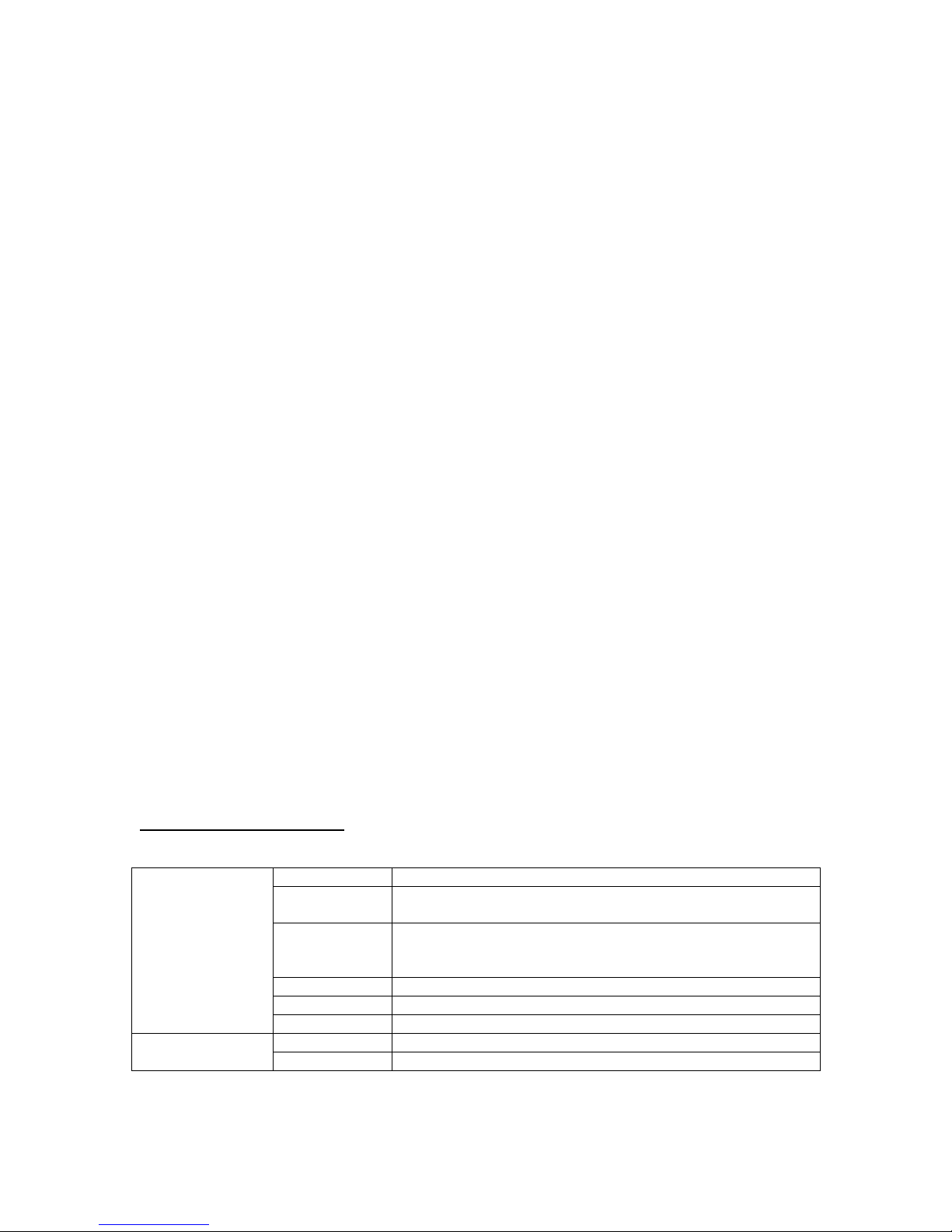
• POWER SUPPLY LEDs:
Located on rear of unit next to AC power input.
Power Supply LED Table
Table 1 –1: Power supplies LEDs indictor definitions
Top LED
(Status)
Bottom LED
(AC Power)
Green No fault detected in this power supply
Green/Amber
flashing
Green flashing Power supply will start within 20 seconds or software shutdown
Amber flashing Failed self test
Amber Fault detected in this power supply
Off System in standby mode or interlock(s) disabled
Green AC power is connected to this power supply
Off No AC power connected to this supply
Power supply failed to restart after a prolonged fault
(software shutdown mode won’t restart unless power switch is
cycled).

2
SYSTEM LEDs:
Table 1 – 2: Processor and I/O board LEDS:
On the I/O Board: On the Processor Board:
(In front of PCI slot 1) (Behind processor 1 and 2. Impossible to view )
Silk screen
Aux 5v CR47 n/a
+12v CR1 CR505
5V CR2 CR504
+3.3v n/a CR501
+2.5v n/a CR503
VTT n/a CR502
ROC 2 CR6 n/a
ROC 3 CR5 n/a
ROC 4 CR4 n/a
ROC 5 CR7 n/a
ROC 6 CR8 n/a
NOTE: If any of the voltages are missing on the System I/O board, the system will not come out of
reset (won’t boot)
The voltage level LEDs are an indication that the voltage rail is present when ON (green). The Aux 5v
should be present all the time the power cord is plugged in and connected to facility power.
• INTERLOCK LEDs:
Interlock circuitry exists to pinpoint missing or unseated processor, VRM, memory board, or I/O
module. (NOTE: Chassis panels are not connected to interlocks). The interlock LEDs can be view on
the top of the system along with their corresponding label.
• I/O BOARD LEDs:
Definitions to be added later.
• PORT 84 LEDs:
Port 84 LEDs will not be populated on production machines. If a PCI Port 84 card is being used, it
must be installed in one of the primary/compatibility bus slots 7, 8 or 9.
CAUTION: Be aware that whenever power is applied to the system (power cord plugged in), even
when the power switch is OFF, there is +5v power on inside the system. The AUX 5V
power is ON anytime the power supply is plugged in and the AUX 5V LED on the I/O
board should also be ON to indicate its presence. This should also provide power for the
IMD, which should also be ON.
• HOT PLUG PCI SLOT LEDS:
Each hot plug PCI slot is accompanied with an LED to indicate whether it’s active. If the LED is not
ON it could mean one of two things. First the hot plug latch must be in the down position and second
it must not be disabled in software.

3
Section 2
SYSTEM BOARD SWITCHES:
I/O CONFIGURATION SWITCH (SW1)
Table 1 – 3:
SW1 Processor Board Configuration Switch
Switch Function Default
S1 On-board Video Disable OFF
S2 Configuration Lock OFF
S3 Rack Mount Configuration OFF
S4 Disable Floppy Boot OFF
S5 Boot Password Disable OFF
S6 Clear Configuration Contents OFF
Located on I/O board in front of PCI slots 10 and 11.
PROCESSOR CORE / BUS FREQUENCY RATIO SWITCH (SW1 AND SW2)
Located on Processor board on the left side of the memory board connector.
Table 1 - 3
Switch Bus / Core
1 2 3 4 Ratio
0 0 0 0 1 / 2
0 0 0 1 1 / 6
0 0 1 0 1 / 4
0 0 1 1 1 / 8
0 1 0 0 1 / 3
0 1 0 1 1 / 7
0 1 1 0 1 / 5
0 1 1 1 Res.
1 0 0 0 2 / 5
1 0 0 1 2 / 13
1 0 1 0 2 / 9
1 0 1 1 2 / 3
1 1 0 0 2 / 7
1 1 0 1 2 / 15
1 1 1 0 2 / 11
1 1 1 1 1 / 2
0 = Closed
1 = Open
Default is all switches “off”. In this state the ROM interrogates the installed processors and
determines the nominal Bus / Core Ratio the system will operate.
 Loading...