

HP procurve switch zl Installation Manual

ProCurve Switch zl
Internal Power Supply
Installation Guide
www.procurve.com


ProCurve Switch zl
Internal Power Supplies
Installation Guide

© Copyright 2005-2007, Hewlett-Packard Development
Company, L.P.
Publication Number
5991-8553
August 2007
Disclaimer
HEWLETT-PACKARD COMPANY MAKES NO WARRANTY
OF ANY KIND WITH REGARD TO THIS MATERIAL,
INCLUDING, BUT NOT LIMITED TO, THE IMPLIED
WARRANTIES OF MERCHANTABILITY AND FITNESS
FOR A PARTICULAR PURPOSE. Hewlett-Packard shall not
be liable for errors contained herein or for incidental or
consequential damages in connection with the furnishing,
performance, or use of this material.
The information contained herein is subject to change
without notice. The only warranties for HP products and
services are set forth in the express warranty statements
accompanying such products and services. Nothing herein
should be construed as constituting an additional warranty.
HP shall not be liable for technical or editorial errors or
omissions contained herein.
Hewlett-Packard assumes no responsibility for the use or
reliability of its software on equipment that is not furnished
by Hewlett-Packard.
Applicable Products
ProCurve Switch zl Internal
Power Supply
ProCurve Switch zl 220V Internal
Power Supply
ProCurve Switch 5406zl (J8697A)
ProCurve Switch 5406zl-48G (J8699A)
ProCurve Switch 5412zl (J8698A)
ProCurve Switch 5412zl-96G (J8700A)
ProCurve Switch 8212zl (J8715A)
ProCurve Switch zl Power Supply Shelf (J8714A)
(J8712A)
(J8713A)
War ranty
See the Customer Support/Warranty booklet included with
the product.
A copy of the specific warranty terms applicable to your
Hewlett-Packard products and replacement parts can be
obtained from your HP Sales and Service Office or
authorized dealer.
Safety
Before installing and operating these products, please read
the “Installation Cautions” on page 4, and the safety information on page 11.
Hewlett-Packard Company
8000 Foothills Boulevard, m/s 5552
Roseville, California 95747-5552
http://www.procurve.com

Contents
Description. . . . . . . . . . . . . . . . . . . . . . . . . . . . . . . . . . . . . . . . . . . . . . . . . . . . . . 1
Installing the Power Supply . . . . . . . . . . . . . . . . . . . . . . . . . . . . . . . . . . . . . . . . 4
Installation Cautions: . . . . . . . . . . . . . . . . . . . . . . . . . . . . . . . . . . . . . . . . . 4
Installation Steps . . . . . . . . . . . . . . . . . . . . . . . . . . . . . . . . . . . . . . . . . . . . . 5
Troubleshooting. . . . . . . . . . . . . . . . . . . . . . . . . . . . . . . . . . . . . . . . . . . . . . . . . . 8
Customer Support Services . . . . . . . . . . . . . . . . . . . . . . . . . . . . . . . . . . . . . . . . 8
Specifications. . . . . . . . . . . . . . . . . . . . . . . . . . . . . . . . . . . . . . . . . . . . . . . . . . . . 9
Physical . . . . . . . . . . . . . . . . . . . . . . . . . . . . . . . . . . . . . . . . . . . . . . . . . . . . . 9
Electrical . . . . . . . . . . . . . . . . . . . . . . . . . . . . . . . . . . . . . . . . . . . . . . . . . . . 9
Environmental . . . . . . . . . . . . . . . . . . . . . . . . . . . . . . . . . . . . . . . . . . . . . . . 9
Safety . . . . . . . . . . . . . . . . . . . . . . . . . . . . . . . . . . . . . . . . . . . . . . . . . . . . . 10
Safety Information. . . . . . . . . . . . . . . . . . . . . . . . . . . . . . . . . . . . . . . . . . . . . . . 11
Informations concernant la sécurité. . . . . . . . . . . . . . . . . . . . . . . . . . . . . . . . 12
Hinweise zur Sicherheit . . . . . . . . . . . . . . . . . . . . . . . . . . . . . . . . . . . . . . . . . . 13
Considerazioni sulla sicurezza. . . . . . . . . . . . . . . . . . . . . . . . . . . . . . . . . . . . . 14
Consideraciones sobre seguridad . . . . . . . . . . . . . . . . . . . . . . . . . . . . . . . . . . 15
Safety Information (Japan) . . . . . . . . . . . . . . . . . . . . . . . . . . . . . . . . . . . . . . . 16
Safety Information (China) . . . . . . . . . . . . . . . . . . . . . . . . . . . . . . . . . . . . . . . 17
EMC Regulatory Statements . . . . . . . . . . . . . . . . . . . . . . . . . . . . . . . . . . . . . . 18
U.S.A. . . . . . . . . . . . . . . . . . . . . . . . . . . . . . . . . . . . . . . . . . . . . . . . . . . . . . 18
Canada . . . . . . . . . . . . . . . . . . . . . . . . . . . . . . . . . . . . . . . . . . . . . . . . . . . . 18
Australia/New Zealand . . . . . . . . . . . . . . . . . . . . . . . . . . . . . . . . . . . . . . . 18
Japan . . . . . . . . . . . . . . . . . . . . . . . . . . . . . . . . . . . . . . . . . . . . . . . . . . . . . . 18
Korea . . . . . . . . . . . . . . . . . . . . . . . . . . . . . . . . . . . . . . . . . . . . . . . . . . . . . . 19
Taiwan . . . . . . . . . . . . . . . . . . . . . . . . . . . . . . . . . . . . . . . . . . . . . . . . . . . . 19
European Community Declaration of Conformity . . . . . . . . . . . . . . . . 19
Recycle Statements. . . . . . . . . . . . . . . . . . . . . . . . . . . . . . . . . . . . . . . . . . . . . . 20
Waste Electrical and Electronic Equipment (WEEE) Statements . . . 20
iii


Description
ProCurve Switch zl Internal Power Supplies
Description
The ProCurve Switch zl Internal Power Supply (J8712A or J8713A) is a
redundant power supply that you can add to any of the ProCurve Series zl
switches to provide additional switch reliability. These power supplies can
also be added to the ProCurve Power Supply Shelf (J8714A) to provide
additional PoE power to any of the zl switches.
Features:
■ power redundancy—if any one of the power supplies should fail, the
remaining supply or supplies provide the power to con tinue running a fully
loaded Series 5400zl or 8200zl Switch.
■ power load sharing—with two supplies installed, each shares the power
load, which increases the life of both of the power supplies.
■ “hot swap” operation—you can add or replace one of the Power
Supplies without having to shut down or reboot the switch.
■ automatic fault detection—if the power supply encounters a problem,
the Switch can immediately detect the condition and report it by way of
the Power Status and Fault LEDs on the switch and the Fault LED on the
power supply. Event messages will also be displayed in the switch console
event log and the web browser interface Alert log.
■ Power and Fault LEDs—The Power LED (green) is lit when power is
supplied to the power supply. The Fault LED (orange) is lit when there is
a fault condition with the power supply.
The two power supplies are different in there input and output power
specifications. Any combination of the J8712A and J8713A Power Supplies can
be used. However, be sure to verify the specific power requirements necessary
for your network.
1
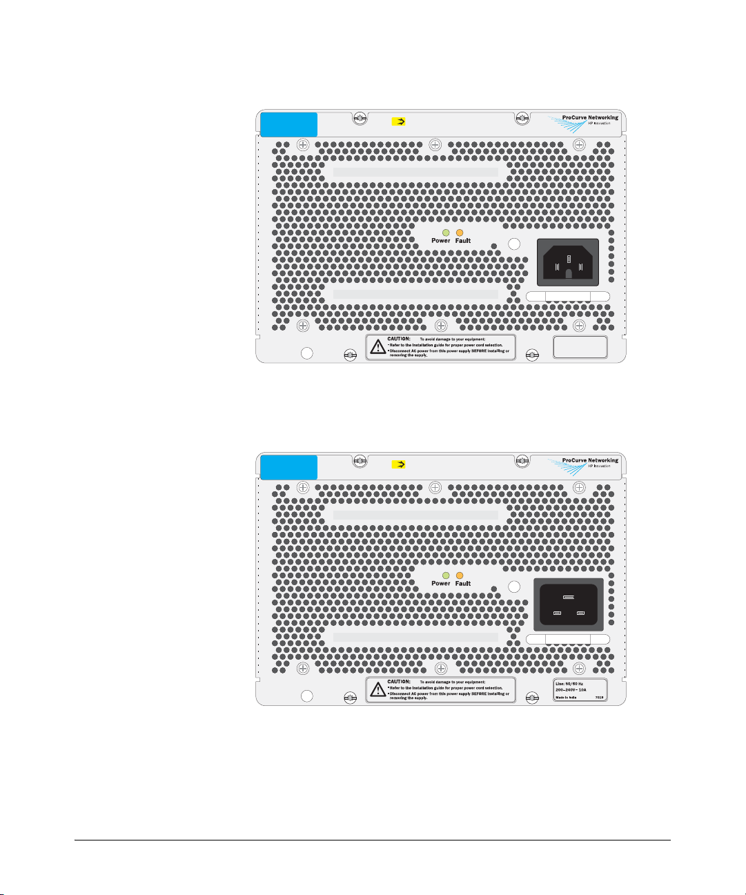
Description
ProCurve Switch zl
875W Power Supply
J8712A
PoE
Unit provides 273 W for PoE
Figure 1. The J8712A power supply
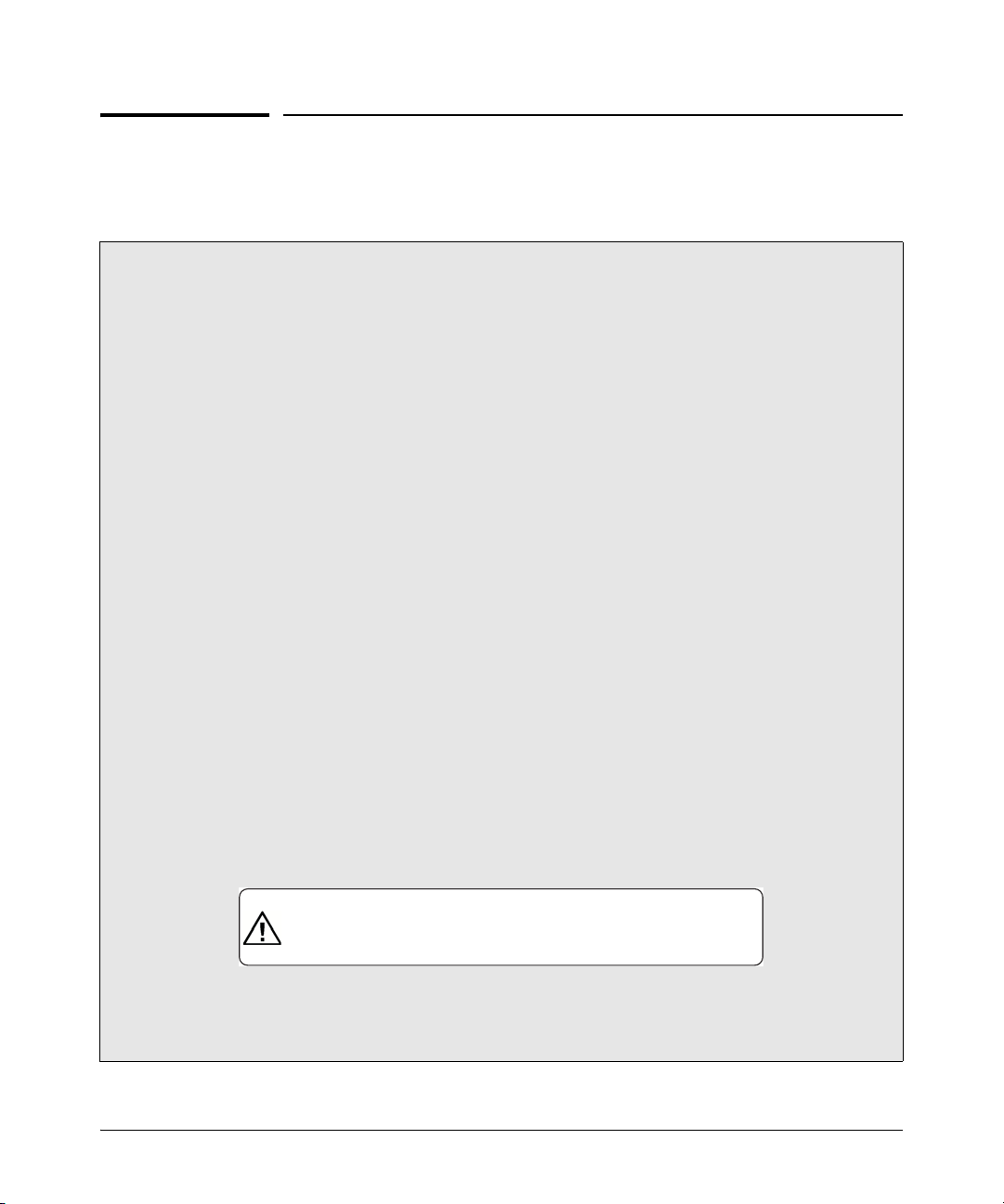
ProCurve Switch zl
1500W Power Supply
J8713A
PoE
Unit provides 900 W for PoE
Line: 50/60 Hz
100127V~ 11.5A (11,5A)
200240V~ 5.7A (5,7A)
Made in India 7019
Figure 2. The J8713A power supply
2

Description
Included Parts. The Switch zl Internal Power Supply has the following
components shipped with it:
■ ProCurve Switch zl Internal Power Supply Installation Guide
(5991-8553), this manual
■ Customer Support/Warranty booklet
■ Power cord, one of the following:
J8712A Power Supply J8713A Power Supply
Region Cable Region Cable
Australia/New Zealand
China
Continental Europe
Denmark
Japan
Switzerland
United Kingdom/
Hong Kong/Singapore
United States/Canada/
Mexico
South Africa
Ta iw a n
8120-5335
8121-1034
8120-5336
8120-5340
8120-5342
8120-5339
8120-5334
8121-0973
8120-5341
8121-0941
Australia/New Zealand
China
Continental Europe
Denmark
Japan
Switzerland
United Kingdom/
Hong Kong/Singapore
United States/Canada/
Mexico
South Africa
Tai wa n
8121-0871
8121-0924
8120-6899
8120-6897
8120-6903
8120-6897
8120-6898
8120-6903*
8121-0915
8120-6903
Japan Power
Cord Warning
* A non-locking power cord is also available. Order part number 8120-6893. To order
go to http://www.hp.com/buy/parts.
3
Installing the Power Supply
Installing the Power Supply
Installation Cautions:
■ Make sure the power source circuits are properly grounded, then use the power cord
supplied with the power supply to connect it to the power source.
If your installation requires a different power cord than the one supplied with the power supply,
be sure the cord is adequately sized for the switch’s current requirements. In addition, be sure
to use a power cord displaying the mark of the safety agency that defines the regulations for
power cords in your country. The mark is your assurance that the power cord can be used safely
with the power supply.
■ When installing the switch, note that the AC outlet should be near the switch and should be
easily accessible in case the switch must be powered off.
■ Ensure the power supply does not overload the power circuits, wiring, and over-current
protection. To determine the possibility of overloading the supply circuits, add together the
ampere ratings of all devices installed on the same circuit as the switch with this power
supply and compare the total with the rating limit for the circuit. The maximum ampere
ratings are usually printed on the devices near their AC power connectors.
■ Do not install the power supply into a switch that is in an environment where the operating
ambient temperature might exceed 55°C (131°F)
8200zl chassis, the ambient temperature must not exceed 40°C (104°F).
■ Make sure the air flow around the sides and back of the switch is not restricted.
■ Make sure that for any switch power supply slot into which a power supply is not installed,
the cover plate is installed to cover the slot. A cover plate is required for safe operation,
and to ensure proper switch cooling.
■ The switch power supplies are hot swappable; they can be installed or removed while the switch
is receiving power from the supply in the other slot. But, as indicated by the caution statement
on the power supply, the supply must not be connected to AC power before being installed
or removed.
CAUTION:
.
Refer to the installation guide for proper power cord selection
.
Disconnect AC power from the power supply BEFORE installing or
removing the supply. Otherwise, damage to the equipment may result.
1
. If the power supply is installed in an
.
1
If you are installing any of the X2 transceivers the operating ambient temperature should not exceed 40°C
(104°F). See transceiver specifications in Appendix A, of the ProCurve Sereis 8200zl Swtich Installation and
Getting Started Guide.
4
 Loading...