

HP ProCurve Secure Router 7203 dl, ProCurve Secure Router 7102 dl Advanced Management And Configuration Manual
Page 1

ProCurve Secure Router
7000dl Series
Advanced Management and
Configuration Guide
December 2005
J04_01
Page 2

© Copyright 2005 Hewlett-Packard Development Company,
L.P. The information contained herein is subject to change without notice. All Rights Reserved.
This document contains proprietary information, w hi ch is
protected by copyright. No par t of th is document may be
photocopied, reproduced, or translated into another language
without the prior written consent of Hew lett-Packar d .
Publication Number
5991-3822
December 200 5
Applicable Products
ProCurve Secure Router 7102 dl (J8752A)
ProCurve Secure Router 7203 dl (J8753A)
Trademark Credit s
Microsoft, Windows, Windows NT, and Windows XP are U.S.
registered trademarks of Microsoft Corporation.
Disclaimer
The information contained in this document is subject to change
without notice.
HEWLETT -P ACKARD COMPANY MAKES NO WARRANTY
OF ANY KIND WITH REGARD TO THIS MATERIAL,
INCLUDING, BUT NOT LIMITED TO, THE IMPLIED
WARRANTIES OF MERCHANTABILITY AND FITNESS
FOR A PAR TICULAR PURPOSE. Hewlett-Packard shall not be
liable for errors contained herein or for incidental or consequential
damages in connection with the furni s hi ng, performance, or use
of this material.
The only warranties for HP products and services are set forth in
the express warranty statements accompanying such products and
services. Nothing herein should be c onst rue d as constituting an
additional warranty. HP shall not be liable for technical or editorial
errors or omissions contained herein.
Hewlett-Packard assumes no responsibility for the use or
reliability of its software on eq ui pment that is not furnished by
Hewlett-Packard.
Warranty
See the Customer Support/Warranty booklet included with the
product.
A copy of the specific warranty terms applicable to your HewlettPackard products and replacement parts can be obtained from your
HP Sales and Service Office or authorized dealer.
Hewlett-Packard Company
8000 Foothills Boulevard
Roseville, California 95747
http://www.procurve.com/
Page 3

Contents
1 Overview
Contents . . . . . . . . . . . . . . . . . . . . . . . . . . . . . . . . . . . . . . . . . . . . . . . . . . . . . . . 1-1
Using This Guide . . . . . . . . . . . . . . . . . . . . . . . . . . . . . . . . . . . . . . . . . . . . . . . 1-3
Understanding Command Syntax Statements . . . . . . . . . . . . . . . . . . . . 1-4
CLI Prompt Convention . . . . . . . . . . . . . . . . . . . . . . . . . . . . . . . . . . 1-4
Observing the IP Address Convention . . . . . . . . . . . . . . . . . . . . . . 1-5
Interface Numbering Convention . . . . . . . . . . . . . . . . . . . . . . . . . . 1-5
Quick Start Sections . . . . . . . . . . . . . . . . . . . . . . . . . . . . . . . . . . . . . . . . . 1-6
Obtaining Additional Information . . . . . . . . . . . . . . . . . . . . . . . . . . . . . . 1-6
Downloading Software Updates . . . . . . . . . . . . . . . . . . . . . . . . . . . . . . . 1-7
Interface Management Options . . . . . . . . . . . . . . . . . . . . . . . . . . . . . . . . . . . 1-9
CLI . . . . . . . . . . . . . . . . . . . . . . . . . . . . . . . . . . . . . . . . . . . . . . . . . . . . . . . . 1-9
Web Browser Interface . . . . . . . . . . . . . . . . . . . . . . . . . . . . . . . . . . . . . . . 1-9
Accessing the Web Browser Interface . . . . . . . . . . . . . . . . . . . . . . . . . 1-10
Using the ProCurve Web Browser Interface . . . . . . . . . . . . . . . . 1-11
CLI Tools . . . . . . . . . . . . . . . . . . . . . . . . . . . . . . . . . . . . . . . . . . . . . . . . . . . . . 1-12
Help Tools . . . . . . . . . . . . . . . . . . . . . . . . . . . . . . . . . . . . . . . . . . . . . . . . 1-12
CLI Help Commands . . . . . . . . . . . . . . . . . . . . . . . . . . . . . . . . . . . . 1-12
Editing Commands . . . . . . . . . . . . . . . . . . . . . . . . . . . . . . . . . . . . . . 1-13
Basic Commands . . . . . . . . . . . . . . . . . . . . . . . . . . . . . . . . . . . . . . . . . . . 1-14
no . . . . . . . . . . . . . . . . . . . . . . . . . . . . . . . . . . . . . . . . . . . . . . . . . . . . 1-14
do . . . . . . . . . . . . . . . . . . . . . . . . . . . . . . . . . . . . . . . . . . . . . . . . . . . . 1-14
exit . . . . . . . . . . . . . . . . . . . . . . . . . . . . . . . . . . . . . . . . . . . . . . . . . . . 1-15
File Management Commands . . . . . . . . . . . . . . . . . . . . . . . . . . . . . . . . 1-15
copy . . . . . . . . . . . . . . . . . . . . . . . . . . . . . . . . . . . . . . . . . . . . . . . . . . 1-15
erase . . . . . . . . . . . . . . . . . . . . . . . . . . . . . . . . . . . . . . . . . . . . . . . . . . 1-18
write . . . . . . . . . . . . . . . . . . . . . . . . . . . . . . . . . . . . . . . . . . . . . . . . . . 1-18
autosynch . . . . . . . . . . . . . . . . . . . . . . . . . . . . . . . . . . . . . . . . . . . . . 1-19
iii
Page 4

Troubleshooting Commands . . . . . . . . . . . . . . . . . . . . . . . . . . . . . . . . . 1-19
reload in . . . . . . . . . . . . . . . . . . . . . . . . . . . . . . . . . . . . . . . . . . . . . . . 1-19
show . . . . . . . . . . . . . . . . . . . . . . . . . . . . . . . . . . . . . . . . . . . . . . . . . . 1-20
show tech . . . . . . . . . . . . . . . . . . . . . . . . . . . . . . . . . . . . . . . . . . . . . 1-20
safe-mode . . . . . . . . . . . . . . . . . . . . . . . . . . . . . . . . . . . . . . . . . . . . . . . . . 1-21
Managing Configuration Files Using a Text Editor . . . . . . . . . . . . . . . . . . 1-24
Using Error Messages to Repair a Configuration . . . . . . . . . . . . . . . . 1-24
Quick Start . . . . . . . . . . . . . . . . . . . . . . . . . . . . . . . . . . . . . . . . . . . . . . . . . . . . 1-27
Accessing the Secure Router OS . . . . . . . . . . . . . . . . . . . . . . . . . . . . . . 1-27
Configuring the Enable Mode Password . . . . . . . . . . . . . . . . . . . . . . . 1-28
Configuring the Ethernet Interface . . . . . . . . . . . . . . . . . . . . . . . . . . . . 1-28
Configuring Telnet Access . . . . . . . . . . . . . . . . . . . . . . . . . . . . . . . . . . . 1-29
Configuring SSH Access . . . . . . . . . . . . . . . . . . . . . . . . . . . . . . . . . . . . . 1-29
Configuring HTTP Access . . . . . . . . . . . . . . . . . . . . . . . . . . . . . . . . . . . 1-30
2 Increasing Bandwidth
Contents . . . . . . . . . . . . . . . . . . . . . . . . . . . . . . . . . . . . . . . . . . . . . . . . . . . . . . . 2-1
Overview . . . . . . . . . . . . . . . . . . . . . . . . . . . . . . . . . . . . . . . . . . . . . . . . . . . . . . 2-2
Configuring MLPPP . . . . . . . . . . . . . . . . . . . . . . . . . . . . . . . . . . . . . . . . . . . . . 2-3
PPP . . . . . . . . . . . . . . . . . . . . . . . . . . . . . . . . . . . . . . . . . . . . . . . . . . . . . . . 2-4
MLPPP . . . . . . . . . . . . . . . . . . . . . . . . . . . . . . . . . . . . . . . . . . . . . . . . . . . . 2-5
LCP Options . . . . . . . . . . . . . . . . . . . . . . . . . . . . . . . . . . . . . . . . . . . . 2-5
MLPPP Header . . . . . . . . . . . . . . . . . . . . . . . . . . . . . . . . . . . . . . . . . . 2-5
MLPPP Configuration Concerns . . . . . . . . . . . . . . . . . . . . . . . . . . . 2-6
Enabling MLPPP . . . . . . . . . . . . . . . . . . . . . . . . . . . . . . . . . . . . . . . . . . . . 2-6
Binding Multiple Carrier Lines to a PPP Interface . . . . . . . . . . . . . . . . 2-6
Configuring MLFR . . . . . . . . . . . . . . . . . . . . . . . . . . . . . . . . . . . . . . . . . . . . . . 2-8
Enabling MLFR . . . . . . . . . . . . . . . . . . . . . . . . . . . . . . . . . . . . . . . . . . . . . 2-9
Binding Multiple Carrier Lines to a Frame Relay Interface . . . . . . . . 2-10
Configuring the Bundle ID . . . . . . . . . . . . . . . . . . . . . . . . . . . . . . . . . . . 2-11
Troubleshooting Multilinks . . . . . . . . . . . . . . . . . . . . . . . . . . . . . . . . . . . . . . 2-12
Standard Procedure . . . . . . . . . . . . . . . . . . . . . . . . . . . . . . . . . . . . . . . . 2-12
Physical Layer . . . . . . . . . . . . . . . . . . . . . . . . . . . . . . . . . . . . . . . . . . 2-12
Data Link Layer . . . . . . . . . . . . . . . . . . . . . . . . . . . . . . . . . . . . . . . . 2-12
iv
Page 5

Troubleshooting MLPPP . . . . . . . . . . . . . . . . . . . . . . . . . . . . . . . . . . . . 2-15
MRRU . . . . . . . . . . . . . . . . . . . . . . . . . . . . . . . . . . . . . . . . . . . . . . . . 2-15
ED . . . . . . . . . . . . . . . . . . . . . . . . . . . . . . . . . . . . . . . . . . . . . . . . . . . 2-16
Troubleshooting MLFR . . . . . . . . . . . . . . . . . . . . . . . . . . . . . . . . . . . . . . 2-16
Quick Start . . . . . . . . . . . . . . . . . . . . . . . . . . . . . . . . . . . . . . . . . . . . . . . . . . . . 2-19
MLPPP Configuration . . . . . . . . . . . . . . . . . . . . . . . . . . . . . . . . . . . . . . . 2-20
MLFR Configuration . . . . . . . . . . . . . . . . . . . . . . . . . . . . . . . . . . . . . . . . 2-21
3 Configuring Backup WAN Connections
Contents . . . . . . . . . . . . . . . . . . . . . . . . . . . . . . . . . . . . . . . . . . . . . . . . . . . . . . . 3-1
Backing Up Primary WAN Connections . . . . . . . . . . . . . . . . . . . . . . . . . . . . 3-5
Analog Backup Connections . . . . . . . . . . . . . . . . . . . . . . . . . . . . . . . . . . 3-5
ISDN-Backup Connections . . . . . . . . . . . . . . . . . . . . . . . . . . . . . . . . . . . 3-6
BRI ISDN . . . . . . . . . . . . . . . . . . . . . . . . . . . . . . . . . . . . . . . . . . . . . . . 3-7
Electrical Specifications for BRI ISDN . . . . . . . . . . . . . . . . . . . . . . 3-9
Backup Modules for the ProCurve Secure Router . . . . . . . . . . . . . . . . 3-9
Standards . . . . . . . . . . . . . . . . . . . . . . . . . . . . . . . . . . . . . . . . . . . . . 3-10
Data Link Layer Protocols . . . . . . . . . . . . . . . . . . . . . . . . . . . . . . . 3-11
Determining a Backup Method . . . . . . . . . . . . . . . . . . . . . . . . . . . . . . . . . . . 3-11
Using Demand Routing for Backup Connections . . . . . . . . . . . . . . . . 3-12
Using Persistent Backup Connections . . . . . . . . . . . . . . . . . . . . . . . . . 3-14
Comparing Demand Routing and Persistent Backup Connections . 3-14
Configuring Demand Routing for Backup Connections . . . . . . . . . . . . . . 3-17
Define the Traffic That Triggers the Connection . . . . . . . . . . . . . . . . 3-18
Specifying a Protocol . . . . . . . . . . . . . . . . . . . . . . . . . . . . . . . . . . . . 3-18
Defining the Source and Destination Addresses . . . . . . . . . . . . . 3-19
Configuring the Demand Interface . . . . . . . . . . . . . . . . . . . . . . . . . . . . 3-20
Creating the Demand Interface . . . . . . . . . . . . . . . . . . . . . . . . . . . 3-21
Configuring an IP Address . . . . . . . . . . . . . . . . . . . . . . . . . . . . . . . 3-22
Matching the Interesting Traffic . . . . . . . . . . . . . . . . . . . . . . . . . . . 3-23
Specifying the connect-mode Option . . . . . . . . . . . . . . . . . . . . . . 3-26
Associating a Resource Pool with the Demand Interface . . . . . . 3-27
Defining a Connect Sequence . . . . . . . . . . . . . . . . . . . . . . . . . . . . . 3-27
Specify the Order in Which Connect Sequences Are Used . . . . . 3-29
v
Page 6

Configure the Number of Connect Sequence Attempts . . . . . . . 3-30
Configure the connect-sequence interface-recovery Option . . . 3-30
Understanding How the connect-sequence Commands Work . . 3-32
Configuring the idle-timeout Option . . . . . . . . . . . . . . . . . . . . . . . 3-34
Configuring the fast-idle Option . . . . . . . . . . . . . . . . . . . . . . . . . . . 3-35
Defining the caller-number . . . . . . . . . . . . . . . . . . . . . . . . . . . . . . . 3-36
Defining the called-number . . . . . . . . . . . . . . . . . . . . . . . . . . . . . . 3-36
Configuring the Hold Queue . . . . . . . . . . . . . . . . . . . . . . . . . . . . . . 3-36
Configuring the BRI or Modem Interface . . . . . . . . . . . . . . . . . . . . . . . 3-37
Accessing the BRI or Modem Interface . . . . . . . . . . . . . . . . . . . . . 3-38
Configuring the ISDN Signaling (Switch) Type . . . . . . . . . . . . . . 3-38
Configuring an LDN for ISDN BRI S/T Modules . . . . . . . . . . . . . 3-39
Configuring a SPID and LDN for ISDN BRI U Modules . . . . . . . 3-40
Setting the Country for the Modem Interface . . . . . . . . . . . . . . . 3-40
Assigning BRI or Modem Interface to the Resource Pool . . . . . 3-41
Activating the Interface . . . . . . . . . . . . . . . . . . . . . . . . . . . . . . . . . . 3-41
Caller ID Options for ISDN BRI Backup Modules (Optional) . . 3-42
Configuring a Floating Static Route for the Demand Interface . . . . . 3-42
Configuring PPP Authentication for an ISDN Connection . . . . . . . . 3-43
Enabling PPP Authentication for All Demand Interfaces . . . . . . 3-43
Configuring PAP Authentication for a Demand Interface . . . . . 3-44
Configuring CHAP Authentication for a Demand Interface . . . . 3-44
Configuring the Username and Password That the Router
Expects to Receive . . . . . . . . . . . . . . . . . . . . . . . . . . . . . . . . . . . . . 3-44
Example of Demand Routing with PAP Authentication for a
Backup Connection . . . . . . . . . . . . . . . . . . . . . . . . . . . . . . . . . . . . . . . . . 3-45
Configuring Peer IP Address . . . . . . . . . . . . . . . . . . . . . . . . . . . . . 3-46
Setting the MTU for Demand Interfaces . . . . . . . . . . . . . . . . . . . . . . . 3-46
Configuring a Persistent Backup Connection . . . . . . . . . . . . . . . . . . . . . . . 3-47
Configuring the Physical Interface for a Persistent Backup
Connection . . . . . . . . . . . . . . . . . . . . . . . . . . . . . . . . . . . . . . . . . . . . . . . . 3-47
Configuring a BRI Interface (ISDN Only) . . . . . . . . . . . . . . . . . . . 3-47
Configuring a Modem Interface (Analog Only) . . . . . . . . . . . . . . 3-51
Using the Modem for Console Dial-In . . . . . . . . . . . . . . . . . . . . . . 3-53
Replacing Incoming Caller ID for BRI and Modem Interfaces . . . . . 3-53
vi
Page 7

Configuring a Logical Interface for a Persistent Backup
Connection . . . . . . . . . . . . . . . . . . . . . . . . . . . . . . . . . . . . . . . . . . . . . . . . 3-54
Creating a Backup PPP Interface . . . . . . . . . . . . . . . . . . . . . . . . . . 3-55
Activating the Interface . . . . . . . . . . . . . . . . . . . . . . . . . . . . . . . . . . 3-55
Setting an IP Address . . . . . . . . . . . . . . . . . . . . . . . . . . . . . . . . . . . . 3-56
Enabling PPP Authentication . . . . . . . . . . . . . . . . . . . . . . . . . . . . . 3-56
Configuring Persistent Backup Settings for a Primary
Connection . . . . . . . . . . . . . . . . . . . . . . . . . . . . . . . . . . . . . . . . . . . . . . . . 3-58
Accessing the Primary Connection’s Logical Interface . . . . . . . . 3-58
Setting the Backup Call Mode . . . . . . . . . . . . . . . . . . . . . . . . . . . . 3-59
Adding a Number to a Backup Dial List . . . . . . . . . . . . . . . . . . . . 3-63
Controlling When a Backup Connection Can Be Established . . 3-64
Setting Backup Timers . . . . . . . . . . . . . . . . . . . . . . . . . . . . . . . . . . 3-66
Configuring a Floating Static Route for a Persistent Backup
Connection . . . . . . . . . . . . . . . . . . . . . . . . . . . . . . . . . . . . . . . . . . . . . . . . 3-67
Configuring Persistent Backup for Multiple Connections . . . . . . . . . 3-69
Viewing Backup Configurations and Troubleshooting Backup
Connections . . . . . . . . . . . . . . . . . . . . . . . . . . . . . . . . . . . . . . . . . . . . . . . . . . 3-70
Viewing Information about BRI and Modem Interfaces and
Troubleshooting Problems . . . . . . . . . . . . . . . . . . . . . . . . . . . . . . . . . . . 3-70
Viewing the Status and Configuration of Backup Interfaces . . . 3-71
Viewing Information about Demand Routing and Troubleshooting
Problems . . . . . . . . . . . . . . . . . . . . . . . . . . . . . . . . . . . . . . . . . . . . . . . . . . 3-75
Viewing the Status of the Demand Interface . . . . . . . . . . . . . . . . 3-75
Viewing a Summary of Information about the Demand
Interface . . . . . . . . . . . . . . . . . . . . . . . . . . . . . . . . . . . . . . . . . . . . . . 3-77
Viewing Demand Sessions . . . . . . . . . . . . . . . . . . . . . . . . . . . . . . . 3-78
Viewing the Resource Pool . . . . . . . . . . . . . . . . . . . . . . . . . . . . . . . 3-78
Show the Running-Config for the Demand Interface . . . . . . . . . 3-79
Troubleshooting Demand Routing . . . . . . . . . . . . . . . . . . . . . . . . 3-79
Checking the Demand Interface . . . . . . . . . . . . . . . . . . . . . . . . . . . 3-79
Checking the ACL That Defines the Interesting Traffic . . . . . . . 3-80
Troubleshooting the Backup Connection . . . . . . . . . . . . . . . . . . . 3-81
Test Calls for ISDN Lines . . . . . . . . . . . . . . . . . . . . . . . . . . . . . . . . 3-83
Troubleshooting PPP for a Demand Routing Backup
Connection . . . . . . . . . . . . . . . . . . . . . . . . . . . . . . . . . . . . . . . . . . . . 3-84
vii
Page 8

Viewing Information about Persistent Backup Connections and
Troubleshooting Problems . . . . . . . . . . . . . . . . . . . . . . . . . . . . . . . . . . . 3-84
Viewing Backup Settings . . . . . . . . . . . . . . . . . . . . . . . . . . . . . . . . . 3-85
Viewing the Backup PPP Interface . . . . . . . . . . . . . . . . . . . . . . . . 3-87
Monitoring the Dial-Up Process . . . . . . . . . . . . . . . . . . . . . . . . . . . . . . 3-87
Troubleshooting Persistent Backup Connections . . . . . . . . . . . . . . . 3-89
Standard Procedures . . . . . . . . . . . . . . . . . . . . . . . . . . . . . . . . . . . . 3-89
Quick Start . . . . . . . . . . . . . . . . . . . . . . . . . . . . . . . . . . . . . . . . . . . . . . . . . . . . 3-94
Configuring Demand Routing for Backup Connections . . . . . . . . . . . 3-94
Configuring a Persistent Backup Connection . . . . . . . . . . . . . . . . . . 3-101
Backing up a Connection with an ISDN BRI S/T Backup Module . 3-105
Backing up a Connection with an Analog Module . . . . . . . . . . . . . . 3-107
4 ProCurve Secure Router OS Firewall—Protecting the
Internal, Trusted Network
Contents . . . . . . . . . . . . . . . . . . . . . . . . . . . . . . . . . . . . . . . . . . . . . . . . . . . . . . . 4-1
Overview . . . . . . . . . . . . . . . . . . . . . . . . . . . . . . . . . . . . . . . . . . . . . . . . . . . . . . 4-3
Advantages of an Integrated Firewall . . . . . . . . . . . . . . . . . . . . . . . . . . . 4-3
Stateful-Inspection Firewalls . . . . . . . . . . . . . . . . . . . . . . . . . . . . . . . . . . 4-4
Packet-Filtering Firewall . . . . . . . . . . . . . . . . . . . . . . . . . . . . . . . . . . 4-4
Circuit-level Gateway . . . . . . . . . . . . . . . . . . . . . . . . . . . . . . . . . . . . 4-5
Application-level Gateway . . . . . . . . . . . . . . . . . . . . . . . . . . . . . . . . 4-7
Attack Checking . . . . . . . . . . . . . . . . . . . . . . . . . . . . . . . . . . . . . . . . . . . . 4-9
SYN-flood Attacks . . . . . . . . . . . . . . . . . . . . . . . . . . . . . . . . . . . . . . 4-10
WinNuke Attacks . . . . . . . . . . . . . . . . . . . . . . . . . . . . . . . . . . . . . . . 4-11
Reflexive Traffic . . . . . . . . . . . . . . . . . . . . . . . . . . . . . . . . . . . . . . . . 4-12
Event Logging . . . . . . . . . . . . . . . . . . . . . . . . . . . . . . . . . . . . . . . . . . . . . 4-12
viii
Configuring Attack Checking . . . . . . . . . . . . . . . . . . . . . . . . . . . . . . . . . . . . 4-14
Enabling the Secure Router OS Firewall . . . . . . . . . . . . . . . . . . . . . . . 4-14
Enabling and Disabling Optional Attack Checks . . . . . . . . . . . . . . . . 4-15
Checking Reflexive Traffic . . . . . . . . . . . . . . . . . . . . . . . . . . . . . . . . . . . 4-16
Configuring Stealth Mode . . . . . . . . . . . . . . . . . . . . . . . . . . . . . . . . . . . . 4-17
Page 9

Configuring ALGs . . . . . . . . . . . . . . . . . . . . . . . . . . . . . . . . . . . . . . . . . . . . . . 4-18
Enabling the FTP ALG . . . . . . . . . . . . . . . . . . . . . . . . . . . . . . . . . . . . . . 4-19
Enabling the H.323 ALG for Voice and Videoconferencing . . . . . . . . 4-19
Enabling the SIP ALG for Voice over IP . . . . . . . . . . . . . . . . . . . . . . . . 4-19
Enabling the PPTP ALG for VPNs . . . . . . . . . . . . . . . . . . . . . . . . . . . . . 4-20
Enabling Firewall Traversal . . . . . . . . . . . . . . . . . . . . . . . . . . . . . . . . . . 4-20
Configuring Timeouts for Sessions . . . . . . . . . . . . . . . . . . . . . . . . . . . . . . . 4-21
Setting the Timeout for a Protocol . . . . . . . . . . . . . . . . . . . . . . . . . . . . 4-21
Setting Timeouts for Specific TCP and UDP Applications . . . . . . . . 4-22
Configuring Logging . . . . . . . . . . . . . . . . . . . . . . . . . . . . . . . . . . . . . . . . . . . . 4-23
Specifying the Priority Level for Logged Events . . . . . . . . . . . . . . . . . 4-24
Specifying How Many Attacks Generate a Log . . . . . . . . . . . . . . . . . . 4-26
Specifying How Many Policy Matches Generate a Log . . . . . . . . . . . 4-26
Forwarding Logs to a Syslog Server . . . . . . . . . . . . . . . . . . . . . . . . . . . 4-27
Forwarding Logs to an Email Address . . . . . . . . . . . . . . . . . . . . . . . . . 4-29
Quick Start . . . . . . . . . . . . . . . . . . . . . . . . . . . . . . . . . . . . . . . . . . . . . . . . . . . . 4-31
5 Applying Access Control to Router Interfaces
Contents . . . . . . . . . . . . . . . . . . . . . . . . . . . . . . . . . . . . . . . . . . . . . . . . . . . . . . . 5-1
Access Control for Interfaces on the ProCurve Secure Router . . . . . . . . . 5-3
Access Control Mechanisms . . . . . . . . . . . . . . . . . . . . . . . . . . . . . . . . . . 5-4
Using ACLs Alone to Configure Access Control . . . . . . . . . . . . . . . . . . . . . 5-5
Configure ACLs . . . . . . . . . . . . . . . . . . . . . . . . . . . . . . . . . . . . . . . . . . . . . 5-6
ACL Entries . . . . . . . . . . . . . . . . . . . . . . . . . . . . . . . . . . . . . . . . . . . . . 5-6
Types of ACLs . . . . . . . . . . . . . . . . . . . . . . . . . . . . . . . . . . . . . . . . . . . 5-6
Creating an ACL . . . . . . . . . . . . . . . . . . . . . . . . . . . . . . . . . . . . . . . . . 5-8
Creating a Standard ACL . . . . . . . . . . . . . . . . . . . . . . . . . . . . . . . . . . 5-8
Creating an Extended ACL . . . . . . . . . . . . . . . . . . . . . . . . . . . . . . . 5-11
Entry Order . . . . . . . . . . . . . . . . . . . . . . . . . . . . . . . . . . . . . . . . . . . . 5-15
Adding a Descriptive Tag to an ACL . . . . . . . . . . . . . . . . . . . . . . . 5-17
Editing an Existing ACL . . . . . . . . . . . . . . . . . . . . . . . . . . . . . . . . . 5-17
Deleting an Existing ACL . . . . . . . . . . . . . . . . . . . . . . . . . . . . . . . . 5-18
Applying the ACL to an Interface . . . . . . . . . . . . . . . . . . . . . . . . . . . . . 5-18
Selecting the Packet and Controlling the Action . . . . . . . . . . . . . 5-19
ix
Page 10

Controlling FTP, HTTP, and Telnet Access to the Router . . . . . . . . . 5-21
Restricting FTP Access . . . . . . . . . . . . . . . . . . . . . . . . . . . . . . . . . . 5-21
Restricting HTTP Access . . . . . . . . . . . . . . . . . . . . . . . . . . . . . . . . 5-21
Restricting Telnet Access . . . . . . . . . . . . . . . . . . . . . . . . . . . . . . . . 5-22
Examples of Applying ACLs . . . . . . . . . . . . . . . . . . . . . . . . . . . . . . . . . 5-23
Using ACPs to Control Access to Router Interfaces . . . . . . . . . . . . . . . . . 5-25
Enable the Firewall . . . . . . . . . . . . . . . . . . . . . . . . . . . . . . . . . . . . . . . . . 5-25
Configure ACLs . . . . . . . . . . . . . . . . . . . . . . . . . . . . . . . . . . . . . . . . . . . . 5-26
Types of ACLs . . . . . . . . . . . . . . . . . . . . . . . . . . . . . . . . . . . . . . . . . . 5-26
Creating an ACL . . . . . . . . . . . . . . . . . . . . . . . . . . . . . . . . . . . . . . . . 5-28
Creating a Standard ACL . . . . . . . . . . . . . . . . . . . . . . . . . . . . . . . . . 5-28
Creating an Extended ACL . . . . . . . . . . . . . . . . . . . . . . . . . . . . . . . 5-31
Configure ACPs . . . . . . . . . . . . . . . . . . . . . . . . . . . . . . . . . . . . . . . . . . . . 5-34
Action . . . . . . . . . . . . . . . . . . . . . . . . . . . . . . . . . . . . . . . . . . . . . . . . 5-34
Selector . . . . . . . . . . . . . . . . . . . . . . . . . . . . . . . . . . . . . . . . . . . . . . . 5-35
Creating an ACP . . . . . . . . . . . . . . . . . . . . . . . . . . . . . . . . . . . . . . . . 5-35
Creating Entries in the ACP . . . . . . . . . . . . . . . . . . . . . . . . . . . . . . 5-36
Editing ACPs . . . . . . . . . . . . . . . . . . . . . . . . . . . . . . . . . . . . . . . . . . . 5-36
Deleting an ACP . . . . . . . . . . . . . . . . . . . . . . . . . . . . . . . . . . . . . . . . 5-36
Assigning the ACP to an Interface . . . . . . . . . . . . . . . . . . . . . . . . . . . . 5-37
Using the reload Command . . . . . . . . . . . . . . . . . . . . . . . . . . . . . . 5-37
Processing ACPs . . . . . . . . . . . . . . . . . . . . . . . . . . . . . . . . . . . . . . . . . . . 5-38
ACP Action Summary . . . . . . . . . . . . . . . . . . . . . . . . . . . . . . . . . . . 5-41
Traffic Flow through Interfaces with ACPs . . . . . . . . . . . . . . . . . . . . . 5-43
Inbound Interface Has an ACP; Outbound Interface Does
Not Have an ACP . . . . . . . . . . . . . . . . . . . . . . . . . . . . . . . . . . . . . . . 5-44
Inbound Interface Has an ACP; Outbound Interface Has
a Different ACP . . . . . . . . . . . . . . . . . . . . . . . . . . . . . . . . . . . . . . . . 5-44
Inbound Interface Does Not Have an ACP; Outbound
Interface Has an ACP . . . . . . . . . . . . . . . . . . . . . . . . . . . . . . . . . . . . 5-45
Traffic in and out Through a Single Interface . . . . . . . . . . . . . . . 5-46
Examples of ACPs . . . . . . . . . . . . . . . . . . . . . . . . . . . . . . . . . . . . . . . . . . 5-46
x
Page 11

Viewing ACLs and ACPs . . . . . . . . . . . . . . . . . . . . . . . . . . . . . . . . . . . . . . . . 5-49
Displaying ACLs . . . . . . . . . . . . . . . . . . . . . . . . . . . . . . . . . . . . . . . . . . . 5-50
Displaying ACPs . . . . . . . . . . . . . . . . . . . . . . . . . . . . . . . . . . . . . . . . . . . 5-51
Viewing Access Policy Sessions . . . . . . . . . . . . . . . . . . . . . . . . . . . . . . 5-52
Viewing Access Policy Statistics . . . . . . . . . . . . . . . . . . . . . . . . . . . . . . 5-53
Troubleshooting . . . . . . . . . . . . . . . . . . . . . . . . . . . . . . . . . . . . . . . . . . . . . . . 5-54
show Commands . . . . . . . . . . . . . . . . . . . . . . . . . . . . . . . . . . . . . . . . . . . 5-54
Monitoring Packets Matched to an ACP . . . . . . . . . . . . . . . . . . . . . . . 5-54
Clearing Existing Policy Sessions . . . . . . . . . . . . . . . . . . . . . . . . . . . . . 5-54
Clear ACL Counters . . . . . . . . . . . . . . . . . . . . . . . . . . . . . . . . . . . . . . . . 5-56
Debug ACLs . . . . . . . . . . . . . . . . . . . . . . . . . . . . . . . . . . . . . . . . . . . . . . . 5-56
Quick Start . . . . . . . . . . . . . . . . . . . . . . . . . . . . . . . . . . . . . . . . . . . . . . . . . . . . 5-57
Enabling the Built-in Firewall . . . . . . . . . . . . . . . . . . . . . . . . . . . . . . . . 5-58
Configuring an ACL and Applying It Directly to an Interface . . . . . . 5-58
Configuring ACPs . . . . . . . . . . . . . . . . . . . . . . . . . . . . . . . . . . . . . . . . . . 5-60
6 Configuring Network Address Translation
Contents . . . . . . . . . . . . . . . . . . . . . . . . . . . . . . . . . . . . . . . . . . . . . . . . . . . . . . . 6-1
NAT Services on the ProCurve Secure Router . . . . . . . . . . . . . . . . . . . . . . . 6-2
Many-to-One NAT for Outbound Traffic . . . . . . . . . . . . . . . . . . . . . . . . 6-2
Using NAT with PAT . . . . . . . . . . . . . . . . . . . . . . . . . . . . . . . . . . . . . . . . . 6-3
One-to-One NAT for Inbound Traffic . . . . . . . . . . . . . . . . . . . . . . . . . . . 6-5
One-to-One NAT with Port Translation . . . . . . . . . . . . . . . . . . . . . . . . . 6-6
Configuring NAT . . . . . . . . . . . . . . . . . . . . . . . . . . . . . . . . . . . . . . . . . . . . . . . . 6-7
Enabling the Firewall . . . . . . . . . . . . . . . . . . . . . . . . . . . . . . . . . . . . . . . . 6-8
Configuring an ACL . . . . . . . . . . . . . . . . . . . . . . . . . . . . . . . . . . . . . . . . . . 6-8
Types of ACLs . . . . . . . . . . . . . . . . . . . . . . . . . . . . . . . . . . . . . . . . . . . 6-9
Configuring an ACP . . . . . . . . . . . . . . . . . . . . . . . . . . . . . . . . . . . . . . . . . 6-13
Configuring Many-to-One NAT for Outbound Traffic . . . . . . . . . 6-13
Configuring One-to-One NAT for Inbound Traffic . . . . . . . . . . . . 6-14
Configuring One-to-One NAT with Port Translation . . . . . . . . . . 6-14
Assigning the ACP to an Interface . . . . . . . . . . . . . . . . . . . . . . . . . . . . 6-15
xi
Page 12

Viewing ACLs and ACPs . . . . . . . . . . . . . . . . . . . . . . . . . . . . . . . . . . . . . . . . 6-16
Displaying ACLs . . . . . . . . . . . . . . . . . . . . . . . . . . . . . . . . . . . . . . . . . . . 6-17
Displaying ACPs . . . . . . . . . . . . . . . . . . . . . . . . . . . . . . . . . . . . . . . . . . . 6-17
Viewing Access Policy Sessions . . . . . . . . . . . . . . . . . . . . . . . . . . . . . . 6-18
Viewing Access Policy Statistics . . . . . . . . . . . . . . . . . . . . . . . . . . . . . . 6-19
Troubleshooting . . . . . . . . . . . . . . . . . . . . . . . . . . . . . . . . . . . . . . . . . . . . . . . 6-20
Monitoring Packets Matched to an ACP . . . . . . . . . . . . . . . . . . . . . . . 6-20
Clearing Existing Policy Sessions . . . . . . . . . . . . . . . . . . . . . . . . . . . . . 6-21
Clearing ACL Counters . . . . . . . . . . . . . . . . . . . . . . . . . . . . . . . . . . . . . . 6-22
Debugging ACLs . . . . . . . . . . . . . . . . . . . . . . . . . . . . . . . . . . . . . . . . . . . 6-23
Quick Start . . . . . . . . . . . . . . . . . . . . . . . . . . . . . . . . . . . . . . . . . . . . . . . . . . . . 6-24
Using the CLI to Configure Many-to-One NAT . . . . . . . . . . . . . . . . . . 6-24
Using the CLI to Configure One-to-One NAT . . . . . . . . . . . . . . . . . . . . 6-26
7 Setting Up Quality of Service
Contents . . . . . . . . . . . . . . . . . . . . . . . . . . . . . . . . . . . . . . . . . . . . . . . . . . . . . . . 7-1
Overview . . . . . . . . . . . . . . . . . . . . . . . . . . . . . . . . . . . . . . . . . . . . . . . . . . . . . . 7-4
Evaluating Traffic on Your Network . . . . . . . . . . . . . . . . . . . . . . . . . . . . 7-4
QoS Mechanisms on the ProCurve Secure Router . . . . . . . . . . . . . . . . 7-5
ToS Field . . . . . . . . . . . . . . . . . . . . . . . . . . . . . . . . . . . . . . . . . . . . . . . 7-6
First In, First Out . . . . . . . . . . . . . . . . . . . . . . . . . . . . . . . . . . . . . . . 7-10
WFQ . . . . . . . . . . . . . . . . . . . . . . . . . . . . . . . . . . . . . . . . . . . . . . . . . . 7-11
CBWFQ . . . . . . . . . . . . . . . . . . . . . . . . . . . . . . . . . . . . . . . . . . . . . . . 7-11
LLQ . . . . . . . . . . . . . . . . . . . . . . . . . . . . . . . . . . . . . . . . . . . . . . . . . . . 7-11
FRF.12 . . . . . . . . . . . . . . . . . . . . . . . . . . . . . . . . . . . . . . . . . . . . . . . . 7-12
QoS Maps . . . . . . . . . . . . . . . . . . . . . . . . . . . . . . . . . . . . . . . . . . . . . . . . . 7-12
xii
Configuring WFQ . . . . . . . . . . . . . . . . . . . . . . . . . . . . . . . . . . . . . . . . . . . . . . 7-14
Overview . . . . . . . . . . . . . . . . . . . . . . . . . . . . . . . . . . . . . . . . . . . . . . . . . . 7-14
Conversations . . . . . . . . . . . . . . . . . . . . . . . . . . . . . . . . . . . . . . . . . . 7-14
Weight . . . . . . . . . . . . . . . . . . . . . . . . . . . . . . . . . . . . . . . . . . . . . . . . 7-15
Shortcomings . . . . . . . . . . . . . . . . . . . . . . . . . . . . . . . . . . . . . . . . . . 7-15
Packet Marking . . . . . . . . . . . . . . . . . . . . . . . . . . . . . . . . . . . . . . . . . 7-16
Enabling WFQ . . . . . . . . . . . . . . . . . . . . . . . . . . . . . . . . . . . . . . . . . . . . . 7-17
Setting the Queue Size . . . . . . . . . . . . . . . . . . . . . . . . . . . . . . . . . . . . . . 7-18
Page 13

Configuring CBWFQ . . . . . . . . . . . . . . . . . . . . . . . . . . . . . . . . . . . . . . . . . . . . 7-18
Overview . . . . . . . . . . . . . . . . . . . . . . . . . . . . . . . . . . . . . . . . . . . . . . . . . . 7-18
Configuring Classes for CBWFQ . . . . . . . . . . . . . . . . . . . . . . . . . . . . . . 7-19
Creating a QoS Map Entry . . . . . . . . . . . . . . . . . . . . . . . . . . . . . . . 7-20
Defining a Class . . . . . . . . . . . . . . . . . . . . . . . . . . . . . . . . . . . . . . . . 7-20
Allocating Bandwidth to a Class . . . . . . . . . . . . . . . . . . . . . . . . . . 7-26
Assigning the QoS Map to an Interface . . . . . . . . . . . . . . . . . . . . . 7-28
Special Considerations for CBWFQ with Multilinks . . . . . . . . . . . . . 7-28
CBWFQ Example Configuration . . . . . . . . . . . . . . . . . . . . . . . . . . . . . . 7-29
Configuring LLQ . . . . . . . . . . . . . . . . . . . . . . . . . . . . . . . . . . . . . . . . . . . . . . . 7-31
Overview . . . . . . . . . . . . . . . . . . . . . . . . . . . . . . . . . . . . . . . . . . . . . . . . . . 7-31
Determining Bandwidth for the Queue . . . . . . . . . . . . . . . . . . . . . . . . 7-31
Determining Bandwidth for VoIP . . . . . . . . . . . . . . . . . . . . . . . . . . 7-32
Determining Bandwidth for Video Streaming . . . . . . . . . . . . . . . 7-35
Placing Traffic in a Low-Latency Queue . . . . . . . . . . . . . . . . . . . . . . . 7-36
Creating a QoS Map Entry . . . . . . . . . . . . . . . . . . . . . . . . . . . . . . . 7-36
Selecting the Traffic to Be Placed in the Low-Latency Queue . . 7-36
Setting the Bandwidth Guaranteed the Queue . . . . . . . . . . . . . . . 7-41
Marking Low Latency Packets with a ToS Value . . . . . . . . . . . . . 7-42
Assigning the QoS Map to an Interface . . . . . . . . . . . . . . . . . . . . . 7-42
Marking Packets with a ToS value . . . . . . . . . . . . . . . . . . . . . . . . . . . . . . . . 7-43
Creating a QoS Map Entry . . . . . . . . . . . . . . . . . . . . . . . . . . . . . . . 7-44
Selecting the Traffic to Be Marked . . . . . . . . . . . . . . . . . . . . . . . . 7-44
Setting the ToS Value . . . . . . . . . . . . . . . . . . . . . . . . . . . . . . . . . . . . 7-48
Assigning the QoS Map to an Interface . . . . . . . . . . . . . . . . . . . . . 7-49
Example Packet Marking Configuration . . . . . . . . . . . . . . . . . . . . 7-49
Configuring Rate Limiting for Frame Relay . . . . . . . . . . . . . . . . . . . . . . . . 7-50
Overview . . . . . . . . . . . . . . . . . . . . . . . . . . . . . . . . . . . . . . . . . . . . . . . . . . 7-50
Rate Limiting . . . . . . . . . . . . . . . . . . . . . . . . . . . . . . . . . . . . . . . . . . . 7-50
FRF.12 . . . . . . . . . . . . . . . . . . . . . . . . . . . . . . . . . . . . . . . . . . . . . . . . 7-51
Configuring Rate Limiting . . . . . . . . . . . . . . . . . . . . . . . . . . . . . . . . . . . 7-52
Setting the Committed Burst Rate . . . . . . . . . . . . . . . . . . . . . . . . . 7-52
Setting the Excessive Burst Rate . . . . . . . . . . . . . . . . . . . . . . . . . . 7-53
Configuring Frame Relay Fragmentation . . . . . . . . . . . . . . . . . . . . . . . 7-54
Example Frame Relay QoS Configuration . . . . . . . . . . . . . . . . . . . . . . 7-54
xiii
Page 14

Configuring QoS for Ethernet . . . . . . . . . . . . . . . . . . . . . . . . . . . . . . . . . . . . 7-55
Overview . . . . . . . . . . . . . . . . . . . . . . . . . . . . . . . . . . . . . . . . . . . . . . . . . . 7-55
Rate Limiting . . . . . . . . . . . . . . . . . . . . . . . . . . . . . . . . . . . . . . . . . . . 7-55
Configuring Rate Limiting on an Ethernet Interface . . . . . . . . . . . . . 7-56
Configuring QoS Policies on an Ethernet Interface . . . . . . . . . . . . . . 7-56
Example: Configuring QoS for VoIP . . . . . . . . . . . . . . . . . . . . . . . . . . . . . . 7-57
Enabling Application-Level Gateways for Applications with
Special Needs . . . . . . . . . . . . . . . . . . . . . . . . . . . . . . . . . . . . . . . . . . . . . . 7-58
Enabling SIP Services . . . . . . . . . . . . . . . . . . . . . . . . . . . . . . . . . . . . . . . 7-59
Defining VoIP Traffic . . . . . . . . . . . . . . . . . . . . . . . . . . . . . . . . . . . . . . . 7-60
Determining the Required Bandwidth . . . . . . . . . . . . . . . . . . . . . . . . . 7-61
Marking Signaling Traffic for Special Treatment . . . . . . . . . . . . . . . . 7-62
Configuring Frame Relay Rate Limiting . . . . . . . . . . . . . . . . . . . . . . . . 7-63
Monitoring QoS . . . . . . . . . . . . . . . . . . . . . . . . . . . . . . . . . . . . . . . . . . . . . . . . 7-64
Viewing QoS Maps . . . . . . . . . . . . . . . . . . . . . . . . . . . . . . . . . . . . . . . . . . 7-65
Managing Queues . . . . . . . . . . . . . . . . . . . . . . . . . . . . . . . . . . . . . . . . . . 7-66
Troubleshooting Common Configuration Problems . . . . . . . . . . . . . 7-67
A Map Becoming Inactive . . . . . . . . . . . . . . . . . . . . . . . . . . . . . . . . 7-67
An Ethernet Interface Refusing to Take a QoS-Policy . . . . . . . . 7-68
xiv
Quick Start . . . . . . . . . . . . . . . . . . . . . . . . . . . . . . . . . . . . . . . . . . . . . . . . . . . . 7-68
Configuring WFQ . . . . . . . . . . . . . . . . . . . . . . . . . . . . . . . . . . . . . . . . . . . 7-68
Configuring CBWFQ . . . . . . . . . . . . . . . . . . . . . . . . . . . . . . . . . . . . . . . . 7-69
Configuring a Low-Latency Queue . . . . . . . . . . . . . . . . . . . . . . . . . . . . 7-71
Marking Packets . . . . . . . . . . . . . . . . . . . . . . . . . . . . . . . . . . . . . . . . . . . 7-72
Configuring Frame Relay Fragmentation . . . . . . . . . . . . . . . . . . . . . . . 7-73
Configuring QoS on an Ethernet Interface . . . . . . . . . . . . . . . . . . . . . 7-73
8 Virtual Private Networks
Contents . . . . . . . . . . . . . . . . . . . . . . . . . . . . . . . . . . . . . . . . . . . . . . . . . . . . . . . 8-1
Overview . . . . . . . . . . . . . . . . . . . . . . . . . . . . . . . . . . . . . . . . . . . . . . . . . . . . . . 8-4
VPN Tunnels . . . . . . . . . . . . . . . . . . . . . . . . . . . . . . . . . . . . . . . . . . . . . . . . 8-4
Page 15

IP Security (IPSec) . . . . . . . . . . . . . . . . . . . . . . . . . . . . . . . . . . . . . . . . . . 8-4
IPSec Headers . . . . . . . . . . . . . . . . . . . . . . . . . . . . . . . . . . . . . . . . . . . 8-5
Hash and Encryption Algorithms . . . . . . . . . . . . . . . . . . . . . . . . . . . 8-6
IPSec VPN Tunnels . . . . . . . . . . . . . . . . . . . . . . . . . . . . . . . . . . . . . . 8-7
Security Associations (SAs) . . . . . . . . . . . . . . . . . . . . . . . . . . . . . . . 8-7
IKE . . . . . . . . . . . . . . . . . . . . . . . . . . . . . . . . . . . . . . . . . . . . . . . . . . . . 8-8
VPN Overlay . . . . . . . . . . . . . . . . . . . . . . . . . . . . . . . . . . . . . . . . . . . . . . . 8-13
Physical Setup . . . . . . . . . . . . . . . . . . . . . . . . . . . . . . . . . . . . . . . . . . . . . . . . . 8-14
Configuring a VPN Using IPSec . . . . . . . . . . . . . . . . . . . . . . . . . . . . . . . . . . 8-15
Configuring IPSec with IKE . . . . . . . . . . . . . . . . . . . . . . . . . . . . . . 8-15
Configuring IPSec with Manual Keying . . . . . . . . . . . . . . . . . . . . . 8-19
How the ProCurve Secure Router Processes IKE Policies
and Crypto Maps . . . . . . . . . . . . . . . . . . . . . . . . . . . . . . . . . . . . . . . 8-20
Configuration Tasks . . . . . . . . . . . . . . . . . . . . . . . . . . . . . . . . . . . . . 8-23
Enabling Crypto Commands . . . . . . . . . . . . . . . . . . . . . . . . . . . . . . . . . 8-23
Configuring IKE Policies . . . . . . . . . . . . . . . . . . . . . . . . . . . . . . . . . . . . 8-23
Peer ID . . . . . . . . . . . . . . . . . . . . . . . . . . . . . . . . . . . . . . . . . . . . . . . . 8-24
Initiate and Response Mode . . . . . . . . . . . . . . . . . . . . . . . . . . . . . . 8-26
Attribute Policy . . . . . . . . . . . . . . . . . . . . . . . . . . . . . . . . . . . . . . . . 8-28
Enabling NAT-Traversal (NAT-T) for a Client-to-Site VPN . . . . 8-31
Configuring a Peer’s Remote ID and Preshared Key . . . . . . . . . . . . . 8-32
Site-to-Site Configuration . . . . . . . . . . . . . . . . . . . . . . . . . . . . . . . . 8-33
Client-to-Site Configuration . . . . . . . . . . . . . . . . . . . . . . . . . . . . . . 8-34
Configuring a Remote ID List for a VPN that Uses Digital
Certificates . . . . . . . . . . . . . . . . . . . . . . . . . . . . . . . . . . . . . . . . . . . . 8-34
Mapping the Remote ID to an IKE Policy and Crypto
Map Entry . . . . . . . . . . . . . . . . . . . . . . . . . . . . . . . . . . . . . . . . . . . . . 8-35
Defining Traffic Allowed over the VPN Tunnel . . . . . . . . . . . . . . . . . . 8-35
Restricting Specified Hosts . . . . . . . . . . . . . . . . . . . . . . . . . . . . . . . 8-36
Permitting Local and Remote Networks . . . . . . . . . . . . . . . . . . . . 8-37
Applying the ACL to a Crypto Map . . . . . . . . . . . . . . . . . . . . . . . . 8-38
Example Configuration . . . . . . . . . . . . . . . . . . . . . . . . . . . . . . . . . . 8-39
Enabling Router Traffic to Servers at a Remote
VPN Site . . . . . . . . . . . . . . . . . . . . . . . . . . . . . . . . . . . . . . . . . . . . . . . 8-39
xv
Page 16

Configuring IPSec SA Parameters . . . . . . . . . . . . . . . . . . . . . . . . . . . . . 8-40
Transform Sets . . . . . . . . . . . . . . . . . . . . . . . . . . . . . . . . . . . . . . . . . 8-40
Crypto Maps . . . . . . . . . . . . . . . . . . . . . . . . . . . . . . . . . . . . . . . . . . . 8-42
Applying a Crypto Map to an Interface . . . . . . . . . . . . . . . . . . . . . . . . . 8-46
Granting Remote Users a Private Network Address with IKE
Mode Config (Required for Client-to-Site VPNs) . . . . . . . . . . . . . . . . 8-47
IKE Mode Config . . . . . . . . . . . . . . . . . . . . . . . . . . . . . . . . . . . . . . . 8-47
Configuring an IKE Client Configuration Pool . . . . . . . . . . . . . . . 8-48
Applying the Pool to an IKE Policy . . . . . . . . . . . . . . . . . . . . . . . . 8-49
Using Extended Authentication (Xauth) (Optional) . . . . . . . . . . . . . . 8-49
Configuring an Xauth Server . . . . . . . . . . . . . . . . . . . . . . . . . . . . . 8-50
Configuring an Xauth Host . . . . . . . . . . . . . . . . . . . . . . . . . . . . . . . 8-53
Using Digital Certificates (Optional) . . . . . . . . . . . . . . . . . . . . . . . . . . 8-54
Overview . . . . . . . . . . . . . . . . . . . . . . . . . . . . . . . . . . . . . . . . . . . . . . 8-54
Obtaining Digital Certificates . . . . . . . . . . . . . . . . . . . . . . . . . . . . . 8-57
Managing Certificates . . . . . . . . . . . . . . . . . . . . . . . . . . . . . . . . . . . 8-61
Configuring a VPN using IPSec with Manual Keying . . . . . . . . . . . . . 8-64
Configuring the Transform Set . . . . . . . . . . . . . . . . . . . . . . . . . . . . 8-65
Configuring Crypto Maps for Manual IPSec . . . . . . . . . . . . . . . . . 8-67
Example Configuration . . . . . . . . . . . . . . . . . . . . . . . . . . . . . . . . . . 8-69
xvi
Monitoring a VPN . . . . . . . . . . . . . . . . . . . . . . . . . . . . . . . . . . . . . . . . . . . . . . 8-70
Troubleshooting a VPN That Uses IPSec . . . . . . . . . . . . . . . . . . . . . . . . . . 8-73
Tools and Procedures . . . . . . . . . . . . . . . . . . . . . . . . . . . . . . . . . . . . . . . 8-73
Troubleshooting Commands . . . . . . . . . . . . . . . . . . . . . . . . . . . . . 8-74
Checking WAN Connections . . . . . . . . . . . . . . . . . . . . . . . . . . . . . 8-75
Determining the Source of the Problem: Permitting All
Traffic in a VPN . . . . . . . . . . . . . . . . . . . . . . . . . . . . . . . . . . . . . . . . 8-75
Monitoring the IKE Process using Debug Commands . . . . . . . . 8-76
Comparing VPN Policies . . . . . . . . . . . . . . . . . . . . . . . . . . . . . . . . . 8-80
Returning VPN Policies to Their Defaults . . . . . . . . . . . . . . . . . . . 8-86
Quick Start . . . . . . . . . . . . . . . . . . . . . . . . . . . . . . . . . . . . . . . . . . . . . . . . . . . . 8-88
Configuring a Site-to-Site VPN . . . . . . . . . . . . . . . . . . . . . . . . . . . . . . . . 8-90
Configuring a Client-to-Site VPN . . . . . . . . . . . . . . . . . . . . . . . . . . . . . . 8-94
Obtaining Digital Certificates . . . . . . . . . . . . . . . . . . . . . . . . . . . . . . . 8-100
Page 17

9 Configuring a Tunnel with Generic Routing Encapsulation
Contents . . . . . . . . . . . . . . . . . . . . . . . . . . . . . . . . . . . . . . . . . . . . . . . . . . . . . . . 9-1
Overview . . . . . . . . . . . . . . . . . . . . . . . . . . . . . . . . . . . . . . . . . . . . . . . . . . . . . . 9-2
GRE Tunnels . . . . . . . . . . . . . . . . . . . . . . . . . . . . . . . . . . . . . . . . . . . . . . . 9-2
Advantages and Disadvantages of GRE . . . . . . . . . . . . . . . . . . . . . . . . . 9-3
Configuring GRE . . . . . . . . . . . . . . . . . . . . . . . . . . . . . . . . . . . . . . . . . . . . . . . . 9-4
Creating the Tunnel Interface . . . . . . . . . . . . . . . . . . . . . . . . . . . . . . . . . 9-4
Configuring the Tunnel’s Source and Destination and IP Address . . . 9-4
Configuring the Tunnel Source . . . . . . . . . . . . . . . . . . . . . . . . . . . . 9-5
Configuring the Tunnel Destination . . . . . . . . . . . . . . . . . . . . . . . . 9-6
Configuring the Tunnel’s IP Address . . . . . . . . . . . . . . . . . . . . . . . . 9-7
Configuring the Tunnel Key . . . . . . . . . . . . . . . . . . . . . . . . . . . . . . . . . . . 9-7
Specifying Tunnel Traffic . . . . . . . . . . . . . . . . . . . . . . . . . . . . . . . . . . . . . 9-7
Sending Routing Updates over the Tunnel . . . . . . . . . . . . . . . . . . . 9-8
Sending Multicasts over the Tunnel . . . . . . . . . . . . . . . . . . . . . . . . 9-9
Sending all Traffic to a Network over the Tunnel . . . . . . . . . . . . 9-10
Filtering Traffic that Arrives on the Tunnel . . . . . . . . . . . . . . . . . 9-11
Enabling Checksum Verification . . . . . . . . . . . . . . . . . . . . . . . . . . . . . . 9-12
Troubleshooting GRE Configuration . . . . . . . . . . . . . . . . . . . . . . . . . . . . . . 9-13
The Tunnel Goes Down . . . . . . . . . . . . . . . . . . . . . . . . . . . . . . . . . . . . . 9-13
The Router Does Not Receive Traffic through the Tunnel . . . . . . . . 9-14
The Router Does Not Receive Routing Updates . . . . . . . . . . . . . . . . . 9-14
Quick Start . . . . . . . . . . . . . . . . . . . . . . . . . . . . . . . . . . . . . . . . . . . . . . . . . . . . 9-15
10 Configuring Multicast Support for a Stub Network
Contents . . . . . . . . . . . . . . . . . . . . . . . . . . . . . . . . . . . . . . . . . . . . . . . . . . . . . . 10-1
Overview . . . . . . . . . . . . . . . . . . . . . . . . . . . . . . . . . . . . . . . . . . . . . . . . . . . . . 10-2
Multicast Applications . . . . . . . . . . . . . . . . . . . . . . . . . . . . . . . . . . . . . . 10-2
IP Multicasting . . . . . . . . . . . . . . . . . . . . . . . . . . . . . . . . . . . . . . . . . . . . . 10-3
Multicast Addresses . . . . . . . . . . . . . . . . . . . . . . . . . . . . . . . . . . . . . 10-4
Host Groups . . . . . . . . . . . . . . . . . . . . . . . . . . . . . . . . . . . . . . . . . . . 10-4
xvii
Page 18

IGMP . . . . . . . . . . . . . . . . . . . . . . . . . . . . . . . . . . . . . . . . . . . . . . . . . . . . . 10-5
IGMP Queries . . . . . . . . . . . . . . . . . . . . . . . . . . . . . . . . . . . . . . . . . . 10-6
IGMP Reports . . . . . . . . . . . . . . . . . . . . . . . . . . . . . . . . . . . . . . . . . . 10-6
Multicast Routing Protocols . . . . . . . . . . . . . . . . . . . . . . . . . . . . . . 10-7
IGMP Proxy . . . . . . . . . . . . . . . . . . . . . . . . . . . . . . . . . . . . . . . . . . . . 10-8
Configuring IGMP Proxy for Multicast Stub Routing Support . . . . . . . . 10-10
Enabling IP Multicast Routing . . . . . . . . . . . . . . . . . . . . . . . . . . . . . . . 10-11
Setting the Multicast Helper Address . . . . . . . . . . . . . . . . . . . . . . . . . 10-11
Determining Which Interfaces are Downstream and
Which Upstream . . . . . . . . . . . . . . . . . . . . . . . . . . . . . . . . . . . . . . . . . . 10-12
Configuring a Downstream Interface . . . . . . . . . . . . . . . . . . . . . . . . . 10-13
Configuring an IGMP Multicast Agent . . . . . . . . . . . . . . . . . . . . . 10-13
Enabling IGMP Proxy . . . . . . . . . . . . . . . . . . . . . . . . . . . . . . . . . . 10-14
Enabling Multicast Forwarding . . . . . . . . . . . . . . . . . . . . . . . . . . 10-14
Configuring an Upstream Interface . . . . . . . . . . . . . . . . . . . . . . . . . . 10-15
Tunneling Multicast Traffic through the Internet . . . . . . . . . . . . . . . 10-15
Adding the Router Stack to a Multicast Group . . . . . . . . . . . . . . . . . 10-16
Altering IGMP Query Intervals . . . . . . . . . . . . . . . . . . . . . . . . . . . . . . 10-16
Troubleshooting Multicast Stub Routing and IGMP . . . . . . . . . . . . . . . . 10-19
Strategies and Tools . . . . . . . . . . . . . . . . . . . . . . . . . . . . . . . . . . . . . . . 10-19
Procedure for Troubleshooting Multicast Stub Routing . . . . . . . . . 10-20
xviii
Quick Start . . . . . . . . . . . . . . . . . . . . . . . . . . . . . . . . . . . . . . . . . . . . . . . . . . . 10-23
11 Configuring Multicast Support with PIM-SM
Contents . . . . . . . . . . . . . . . . . . . . . . . . . . . . . . . . . . . . . . . . . . . . . . . . . . . . . . 11-1
Overview . . . . . . . . . . . . . . . . . . . . . . . . . . . . . . . . . . . . . . . . . . . . . . . . . . . . . 11-3
Multicast Trees . . . . . . . . . . . . . . . . . . . . . . . . . . . . . . . . . . . . . . . . . . . . 11-4
RP Tree . . . . . . . . . . . . . . . . . . . . . . . . . . . . . . . . . . . . . . . . . . . . . . . 11-4
SP Tree . . . . . . . . . . . . . . . . . . . . . . . . . . . . . . . . . . . . . . . . . . . . . . . 11-5
Multicast Routing Table . . . . . . . . . . . . . . . . . . . . . . . . . . . . . . . . . . . . . 11-6
Joining a Shared or RP Tree . . . . . . . . . . . . . . . . . . . . . . . . . . . . . . . . . 11-8
Switching from an RP to an SP Tree . . . . . . . . . . . . . . . . . . . . . . . . . . . 11-9
RPs . . . . . . . . . . . . . . . . . . . . . . . . . . . . . . . . . . . . . . . . . . . . . . . . . . . 11-9
Edge Routers . . . . . . . . . . . . . . . . . . . . . . . . . . . . . . . . . . . . . . . . . 11-12
A Source’s DR . . . . . . . . . . . . . . . . . . . . . . . . . . . . . . . . . . . . . . . . . 11-14
Page 19

Building RP and SP Trees When the Source Begins
Multicasting First . . . . . . . . . . . . . . . . . . . . . . . . . . . . . . . . . . . . . . . . . 11-15
A Source Begins Multicasting Before Any Hosts Join
Its Group . . . . . . . . . . . . . . . . . . . . . . . . . . . . . . . . . . . . . . . . . . . . . 11-15
A Host Joins a Group After Routers Have Already
Switched to an SP Tree . . . . . . . . . . . . . . . . . . . . . . . . . . . . . . . . . 11-16
RP Selection . . . . . . . . . . . . . . . . . . . . . . . . . . . . . . . . . . . . . . . . . . . . . . 11-17
PIM-SM Packets . . . . . . . . . . . . . . . . . . . . . . . . . . . . . . . . . . . . . . . . . . . 11-18
Join/Prune Packets . . . . . . . . . . . . . . . . . . . . . . . . . . . . . . . . . . . . 11-18
Register Packets . . . . . . . . . . . . . . . . . . . . . . . . . . . . . . . . . . . . . . . 11-25
Register-Stop Packets . . . . . . . . . . . . . . . . . . . . . . . . . . . . . . . . . . 11-26
Bootstrap Packets . . . . . . . . . . . . . . . . . . . . . . . . . . . . . . . . . . . . . 11-26
Hellos . . . . . . . . . . . . . . . . . . . . . . . . . . . . . . . . . . . . . . . . . . . . . . . . 11-26
Asserts . . . . . . . . . . . . . . . . . . . . . . . . . . . . . . . . . . . . . . . . . . . . . . . 11-26
Configuring PIM-SM . . . . . . . . . . . . . . . . . . . . . . . . . . . . . . . . . . . . . . . . . . . 11-28
Enabling PIM-SM . . . . . . . . . . . . . . . . . . . . . . . . . . . . . . . . . . . . . . . . . . 11-29
Configuring a Static RP Set . . . . . . . . . . . . . . . . . . . . . . . . . . . . . . . . . 11-30
Specifying Static RPs that Support All Groups . . . . . . . . . . . . . 11-31
Specifying a Static RP for a Specific Group . . . . . . . . . . . . . . . . 11-31
Specifying When the Router Switches to the SP Tree . . . . . . . . . . . 11-35
Forcing the Router to Use the RP Tree Permanently . . . . . . . . . . . . 11-36
Changing an Interface’s DR Priority . . . . . . . . . . . . . . . . . . . . . . . . . . 11-36
Changing PIM-SM Timers . . . . . . . . . . . . . . . . . . . . . . . . . . . . . . . . . . . 11-37
Join/Prune Period . . . . . . . . . . . . . . . . . . . . . . . . . . . . . . . . . . . . . . 11-38
Hello Timer . . . . . . . . . . . . . . . . . . . . . . . . . . . . . . . . . . . . . . . . . . . 11-39
Override and Propagation Delay Timers . . . . . . . . . . . . . . . . . . . 11-39
Configuration Examples . . . . . . . . . . . . . . . . . . . . . . . . . . . . . . . . . . . . 11-40
Example 1: Configuring PIM-SM in a Network with
a Headquarters and Two Small Remote Sites . . . . . . . . . . . . . . 11-40
Example 2: Configuring Specific RPs to Support
Specific Groups . . . . . . . . . . . . . . . . . . . . . . . . . . . . . . . . . . . . . . . 11-45
xix
Page 20

Troubleshooting PIM-SM . . . . . . . . . . . . . . . . . . . . . . . . . . . . . . . . . . . . . . . 11-48
Monitoring the Multicast Routing Table . . . . . . . . . . . . . . . . . . . . . . . 11-48
Flags . . . . . . . . . . . . . . . . . . . . . . . . . . . . . . . . . . . . . . . . . . . . . . . . . 11-49
First Line of a Multicast Routing Table Entry . . . . . . . . . . . . . . 11-50
Incoming Interface . . . . . . . . . . . . . . . . . . . . . . . . . . . . . . . . . . . . . 11-52
Outgoing Interface List . . . . . . . . . . . . . . . . . . . . . . . . . . . . . . . . . 11-53
Viewing PIM-SM Information . . . . . . . . . . . . . . . . . . . . . . . . . . . . . . . . 11-54
PIM-SM Troubleshooting Process . . . . . . . . . . . . . . . . . . . . . . . . . . . . 11-56
Troubleshooting an Edge Router . . . . . . . . . . . . . . . . . . . . . . . . . 11-56
Troubleshooting A Router in Conjunction with Its PIM
Neighbors . . . . . . . . . . . . . . . . . . . . . . . . . . . . . . . . . . . . . . . . . . . . 11-61
Quick Start . . . . . . . . . . . . . . . . . . . . . . . . . . . . . . . . . . . . . . . . . . . . . . . . . . . 11-68
12 Link Layer Discovery Protocol
Contents . . . . . . . . . . . . . . . . . . . . . . . . . . . . . . . . . . . . . . . . . . . . . . . . . . . . . . 12-1
Overview . . . . . . . . . . . . . . . . . . . . . . . . . . . . . . . . . . . . . . . . . . . . . . . . . . . . . 12-2
LLDP . . . . . . . . . . . . . . . . . . . . . . . . . . . . . . . . . . . . . . . . . . . . . . . . . . . . . 12-2
LLDP Messages . . . . . . . . . . . . . . . . . . . . . . . . . . . . . . . . . . . . . . . . . . . . 12-3
Viewing LLDP Information . . . . . . . . . . . . . . . . . . . . . . . . . . . . . . . . . . . . . . 12-4
Viewing LLDP Neighbor Information . . . . . . . . . . . . . . . . . . . . . . . . . . 12-5
Viewing Local LLDP Activity . . . . . . . . . . . . . . . . . . . . . . . . . . . . . . . . . 12-8
Viewing Real-Time LLDP Messages: debug lldp Commands . . . . . . . 12-9
Viewing LLDP Timers . . . . . . . . . . . . . . . . . . . . . . . . . . . . . . . . . . . . . . 12-11
xx
Configuring LLDP . . . . . . . . . . . . . . . . . . . . . . . . . . . . . . . . . . . . . . . . . . . . . 12-12
Preventing an Interface from Sending Certain LLDP Messages . . . 12-12
Preventing an Interface from Receiving LLDP Messages . . . . . . . . 12-14
Altering LLDP Timers . . . . . . . . . . . . . . . . . . . . . . . . . . . . . . . . . . . . . . 12-14
Quick Start . . . . . . . . . . . . . . . . . . . . . . . . . . . . . . . . . . . . . . . . . . . . . . . . . . . 12-15
Page 21

13 IP Routing—Configuring RIP, OSPF, BGP, and PBR
Contents . . . . . . . . . . . . . . . . . . . . . . . . . . . . . . . . . . . . . . . . . . . . . . . . . . . . . . 13-1
Overview . . . . . . . . . . . . . . . . . . . . . . . . . . . . . . . . . . . . . . . . . . . . . . . . . . . . . 13-6
Routing Protocols . . . . . . . . . . . . . . . . . . . . . . . . . . . . . . . . . . . . . . . . . . 13-6
Dynamic Routing Protocols Supported on the ProCurve Secure
Router . . . . . . . . . . . . . . . . . . . . . . . . . . . . . . . . . . . . . . . . . . . . . . . . 13-7
How Routing Protocols Work . . . . . . . . . . . . . . . . . . . . . . . . . . . . . 13-7
Advantages and Disadvantages of Routing Protocols . . . . . . . . 13-10
Load Sharing . . . . . . . . . . . . . . . . . . . . . . . . . . . . . . . . . . . . . . . . . . . . . 13-11
Configuring RIP . . . . . . . . . . . . . . . . . . . . . . . . . . . . . . . . . . . . . . . . . . . . . . 13-12
RIP Process . . . . . . . . . . . . . . . . . . . . . . . . . . . . . . . . . . . . . . . . . . . 13-12
RIP Updates, v1 and v2 . . . . . . . . . . . . . . . . . . . . . . . . . . . . . . . . . 13-13
Speeding Convergence: Split Horizon, Poison Reverse,
and Triggered Updates . . . . . . . . . . . . . . . . . . . . . . . . . . . . . . . . . 13-15
RIP Timing Intervals . . . . . . . . . . . . . . . . . . . . . . . . . . . . . . . . . . . 13-17
RIP Configuration Considerations . . . . . . . . . . . . . . . . . . . . . . . . 13-18
Selecting a RIP Version . . . . . . . . . . . . . . . . . . . . . . . . . . . . . . . . . . . . 13-19
Setting a Global RIP Version . . . . . . . . . . . . . . . . . . . . . . . . . . . . 13-20
Setting RIP Versions for Particular Interfaces . . . . . . . . . . . . . . 13-20
Specifying Networks That Will Participate in RIP . . . . . . . . . . . . . . 13-21
Redistributing Routes . . . . . . . . . . . . . . . . . . . . . . . . . . . . . . . . . . . . . . 13-22
Redistributing Connected Routes . . . . . . . . . . . . . . . . . . . . . . . . 13-23
Redistributing OSPF Routes . . . . . . . . . . . . . . . . . . . . . . . . . . . . . 13-24
Enabling and Disabling Route Summarization for Classful
Subnets . . . . . . . . . . . . . . . . . . . . . . . . . . . . . . . . . . . . . . . . . . . . . . . . . . 13-24
Configuring a Passive Interface: Prohibiting an Interface from
Sending Updates . . . . . . . . . . . . . . . . . . . . . . . . . . . . . . . . . . . . . . . . . . 13-26
Altering RIP Intervals . . . . . . . . . . . . . . . . . . . . . . . . . . . . . . . . . . . . . . 13-28
Configuring OSPF . . . . . . . . . . . . . . . . . . . . . . . . . . . . . . . . . . . . . . . . . . . . . 13-29
LSAs . . . . . . . . . . . . . . . . . . . . . . . . . . . . . . . . . . . . . . . . . . . . . . . . . 13-30
Point-to-Point Versus Multi-Access Networks . . . . . . . . . . . . . . 13-30
Areas . . . . . . . . . . . . . . . . . . . . . . . . . . . . . . . . . . . . . . . . . . . . . . . . 13-31
LSA Types . . . . . . . . . . . . . . . . . . . . . . . . . . . . . . . . . . . . . . . . . . . . 13-33
Route Computation . . . . . . . . . . . . . . . . . . . . . . . . . . . . . . . . . . . . 13-35
OSPF Configuration Concerns . . . . . . . . . . . . . . . . . . . . . . . . . . . 13-36
xxi
Page 22

Setting the Router ID . . . . . . . . . . . . . . . . . . . . . . . . . . . . . . . . . . . . . . 13-41
Advertising Networks and Establishing OSPF Areas . . . . . . . . . . . . 13-42
Defining an OSPF Network Within an Area . . . . . . . . . . . . . . . . 13-42
Configuring Stub Areas . . . . . . . . . . . . . . . . . . . . . . . . . . . . . . . . . 13-43
Route Summarization (ABRs): Advertising a Link to
One Area to Routers in Another Area . . . . . . . . . . . . . . . . . . . . . 13-44
Example Configuration of OSPF Areas . . . . . . . . . . . . . . . . . . . . 13-49
Prohibiting the Advertisement of Networks . . . . . . . . . . . . . . . . . . . 13-51
Generating a Default External Route (ASBR) . . . . . . . . . . . . . . . . . . 13-51
Configuring Route Summaries for ASBRs . . . . . . . . . . . . . . . . . . . . . 13-52
Configuring Cost Calculation for a Link . . . . . . . . . . . . . . . . . . . . . . . 13-54
Redistributing Routes Discovered by Other Protocols (ASBRs) . . 13-55
Redistributing RIP Routes . . . . . . . . . . . . . . . . . . . . . . . . . . . . . . 13-56
Redistributing Connected and Static Routes . . . . . . . . . . . . . . . 13-56
Configuring the Default Metric for Redistributed Routes . . . . 13-57
Changing a Router’s DR Priority . . . . . . . . . . . . . . . . . . . . . . . . . . . . . 13-57
Altering OSPF Intervals . . . . . . . . . . . . . . . . . . . . . . . . . . . . . . . . . . . . 13-58
Configuring OSPF Authentication . . . . . . . . . . . . . . . . . . . . . . . . . . . . 13-60
Example OSPF Configuration . . . . . . . . . . . . . . . . . . . . . . . . . . . . . . . 13-61
Configuring BGP . . . . . . . . . . . . . . . . . . . . . . . . . . . . . . . . . . . . . . . . . . . . . . 13-65
BGP Advantages . . . . . . . . . . . . . . . . . . . . . . . . . . . . . . . . . . . . . . . 13-65
VRF and MPLS . . . . . . . . . . . . . . . . . . . . . . . . . . . . . . . . . . . . . . . . 13-66
Multihoming . . . . . . . . . . . . . . . . . . . . . . . . . . . . . . . . . . . . . . . . . . 13-67
BGP Neighbors . . . . . . . . . . . . . . . . . . . . . . . . . . . . . . . . . . . . . . . . 13-68
BGP Messages . . . . . . . . . . . . . . . . . . . . . . . . . . . . . . . . . . . . . . . . 13-68
BGP Configuration Concerns . . . . . . . . . . . . . . . . . . . . . . . . . . . . 13-68
Enabling BGP . . . . . . . . . . . . . . . . . . . . . . . . . . . . . . . . . . . . . . . . . . . . . 13-70
Advertising Local Networks . . . . . . . . . . . . . . . . . . . . . . . . . . . . . . . . . 13-71
Setting the Router ID . . . . . . . . . . . . . . . . . . . . . . . . . . . . . . . . . . . . . . 13-72
Configuring a BGP Neighbor . . . . . . . . . . . . . . . . . . . . . . . . . . . . . . . . 13-72
Setting the BGP Neighbor ID . . . . . . . . . . . . . . . . . . . . . . . . . . . . 13-72
Specifying the Local and Remote AS . . . . . . . . . . . . . . . . . . . . . . 13-73
Load Balancing . . . . . . . . . . . . . . . . . . . . . . . . . . . . . . . . . . . . . . . . . . . 13-74
Balancing Loads over Multiple Connections to the
Same Neighbor: Specifying the Source for Updates . . . . . . . . . 13-74
Balancing Loads over Connections to Different Neighbors . . . 13-76
xxii
Page 23

Creating Prefix Lists: Configuring Filters for Route Exchange . . . . 13-78
Naming the List . . . . . . . . . . . . . . . . . . . . . . . . . . . . . . . . . . . . . . . 13-80
Assigning the Entry an Order . . . . . . . . . . . . . . . . . . . . . . . . . . . . 13-80
Discarding or Allowing Routes . . . . . . . . . . . . . . . . . . . . . . . . . . . 13-80
Specifying the Network Address . . . . . . . . . . . . . . . . . . . . . . . . . 13-80
Specifying the Range of Prefix Lengths . . . . . . . . . . . . . . . . . . . 13-80
Applying Filters . . . . . . . . . . . . . . . . . . . . . . . . . . . . . . . . . . . . . . . 13-81
Example BGP Policies . . . . . . . . . . . . . . . . . . . . . . . . . . . . . . . . . . 13-81
Example Prefix List Configuration . . . . . . . . . . . . . . . . . . . . . . . 13-85
Configuring Route Maps: Creating More Complex Policies
for Route Exchange . . . . . . . . . . . . . . . . . . . . . . . . . . . . . . . . . . . . . . . 13-86
Creating a Route Map Entry . . . . . . . . . . . . . . . . . . . . . . . . . . . . . 13-87
Configuring a Community List . . . . . . . . . . . . . . . . . . . . . . . . . . . 13-88
Configuring an AS Path List . . . . . . . . . . . . . . . . . . . . . . . . . . . . . 13-89
Defining the Routes that a Router Can Advertise . . . . . . . . . . . 13-89
Placing a Route in a Community: Requesting a Neighbor
to Advertise a Route to Certain Peers Only . . . . . . . . . . . . . . . . 13-94
Prepending Private AS Numbers for Load Balancing . . . . . . . . 13-96
Setting a Multi-Exit Discriminator Metric for
Load Balancing . . . . . . . . . . . . . . . . . . . . . . . . . . . . . . . . . . . . . . . . 13-98
Filtering Inbound Routes . . . . . . . . . . . . . . . . . . . . . . . . . . . . . . 13-100
Applying Policies to Inbound Routes . . . . . . . . . . . . . . . . . . . . 13-102
Deleting Communities from a Route . . . . . . . . . . . . . . . . . . . . . 13-103
Applying a Route Map Entry to a BGP Neighbor . . . . . . . . . . . 13-104
Enabling Soft Reconfiguration . . . . . . . . . . . . . . . . . . . . . . . . . . . . . 13-104
Prohibiting the Advertisement of Default Routes . . . . . . . . . . . . . . 13-104
Disabling IGP Synchronization . . . . . . . . . . . . . . . . . . . . . . . . . . . . . 13-105
Configuring Route Summarizations . . . . . . . . . . . . . . . . . . . . . . . . . 13-105
Setting Administrative Distance for BGP Routes . . . . . . . . . . . . . . 13-105
Altering BGP Intervals . . . . . . . . . . . . . . . . . . . . . . . . . . . . . . . . . . . . 13-106
Configuration Examples . . . . . . . . . . . . . . . . . . . . . . . . . . . . . . . . . . . 13-106
Example 1: Baseline BGP Configuration . . . . . . . . . . . . . . . . . 13-107
Example 2: Baseline BGP Configuration for a Router that
Runs an IGP . . . . . . . . . . . . . . . . . . . . . . . . . . . . . . . . . . . . . . . . . 13-109
Example 3: Configuring a Standard BGP Policy on a
Router That Receives Routes to Remote Private Sites . . . . . . 13-111
Example 4: Configuring BGP Policies for a Router That
Multihomes . . . . . . . . . . . . . . . . . . . . . . . . . . . . . . . . . . . . . . . . . . 13-113
xxiii
Page 24

Configuring Load Sharing . . . . . . . . . . . . . . . . . . . . . . . . . . . . . . . . . . . . . 13-120
Configuring Policy-Based Routing . . . . . . . . . . . . . . . . . . . . . . . . . . . . . . 13-123
Overview . . . . . . . . . . . . . . . . . . . . . . . . . . . . . . . . . . . . . . . . . . . . . . . . 13-123
Configuring a Route Map for PBR . . . . . . . . . . . . . . . . . . . . . . . . . . . 13-125
Selecting Traffic for a Route Map Entry . . . . . . . . . . . . . . . . . . . . . . 13-126
Implementing PBR According to Source . . . . . . . . . . . . . . . . . 13-127
Implementing PBR According to Application . . . . . . . . . . . . . 13-130
Implementing PBR According to Traffic Priority . . . . . . . . . . 13-132
Implementing PBR According to Payload Size . . . . . . . . . . . . 13-135
Setting the Routing Policy in a Route Map Entry . . . . . . . . . . . . . . 13-136
Configuring Default Routes in a Route Map Entry . . . . . . . . . 13-138
Using a Route Map to Mark Packets with a QoS Value . . . . . . . . . 13-139
Setting the Don’t Fragment Bit . . . . . . . . . . . . . . . . . . . . . . . . . . . . . 13-141
Assigning a Route Map to an Interface . . . . . . . . . . . . . . . . . . . . . . . 13-142
Applying a Route Map to Router Traffic . . . . . . . . . . . . . . . . . . . . . 13-142
PBR Configuration Examples . . . . . . . . . . . . . . . . . . . . . . . . . . . . . . 13-142
Routing Traffic to a Security Appliance . . . . . . . . . . . . . . . . . . 13-142
Routing Traffic to a Caching Server . . . . . . . . . . . . . . . . . . . . . 13-144
Reserving a Connection for VoIP and Video Traffic . . . . . . . . 13-145
Troubleshooting Routing . . . . . . . . . . . . . . . . . . . . . . . . . . . . . . . . . . . . . . 13-146
Monitoring the Routing Table . . . . . . . . . . . . . . . . . . . . . . . . . . . . . . 13-146
Monitoring Routes . . . . . . . . . . . . . . . . . . . . . . . . . . . . . . . . . . . . . . . . 13-149
Clearing Routes . . . . . . . . . . . . . . . . . . . . . . . . . . . . . . . . . . . . . . . . . . 13-149
Troubleshooting RIP . . . . . . . . . . . . . . . . . . . . . . . . . . . . . . . . . . . . . . 13-151
Router Not Receiving Routes . . . . . . . . . . . . . . . . . . . . . . . . . . . 13-151
Other Routers Not Receiving Routes to the Local
Router’s Subnets . . . . . . . . . . . . . . . . . . . . . . . . . . . . . . . . . . . . . 13-152
Troubleshooting OSPF . . . . . . . . . . . . . . . . . . . . . . . . . . . . . . . . . . . . 13-153
Troubleshooting an Internal Router . . . . . . . . . . . . . . . . . . . . . 13-156
Troubleshooting an ABR . . . . . . . . . . . . . . . . . . . . . . . . . . . . . . . 13-160
Troubleshooting BGP . . . . . . . . . . . . . . . . . . . . . . . . . . . . . . . . . . . . . 13-162
Strategies and Tools . . . . . . . . . . . . . . . . . . . . . . . . . . . . . . . . . . 13-162
Troubleshooting a Prefix List . . . . . . . . . . . . . . . . . . . . . . . . . . . 13-170
Troubleshooting a Route Map . . . . . . . . . . . . . . . . . . . . . . . . . . 13-171
Other Common BGP Problems . . . . . . . . . . . . . . . . . . . . . . . . . 13-172
Monitoring and Troubleshooting PBR . . . . . . . . . . . . . . . . . . . . . . . 13-173
xxiv
Page 25

Quick Start . . . . . . . . . . . . . . . . . . . . . . . . . . . . . . . . . . . . . . . . . . . . . . . . . . 13-176
RIP Routing . . . . . . . . . . . . . . . . . . . . . . . . . . . . . . . . . . . . . . . . . . . . . 13-177
OSPF Routing . . . . . . . . . . . . . . . . . . . . . . . . . . . . . . . . . . . . . . . . . . . 13-177
Configuring an Internal Router . . . . . . . . . . . . . . . . . . . . . . . . . 13-178
Configuring an ABR . . . . . . . . . . . . . . . . . . . . . . . . . . . . . . . . . . . 13-179
Configuring an ASBR . . . . . . . . . . . . . . . . . . . . . . . . . . . . . . . . . . 13-180
Configuring BGP . . . . . . . . . . . . . . . . . . . . . . . . . . . . . . . . . . . . . . . . . 13-181
Configuring PBR . . . . . . . . . . . . . . . . . . . . . . . . . . . . . . . . . . . . . . . . . 13-182
14 Using the Web Browser Interface for Advanced
Configuration Tasks
Contents . . . . . . . . . . . . . . . . . . . . . . . . . . . . . . . . . . . . . . . . . . . . . . . . . . . . . . 14-1
Configuring Access to the Web Browser Interface . . . . . . . . . . . . . . . . . . 14-4
Enabling Access to the Web Browser Interface . . . . . . . . . . . . . . . . . 14-4
Managing AutoSynchTM, Files, Firmware, and Boot Software . . . . . . . . 14-5
AutoSynch™ . . . . . . . . . . . . . . . . . . . . . . . . . . . . . . . . . . . . . . . . . . . . . . 14-5
Configuration . . . . . . . . . . . . . . . . . . . . . . . . . . . . . . . . . . . . . . . . . . . . . . 14-7
Firmware . . . . . . . . . . . . . . . . . . . . . . . . . . . . . . . . . . . . . . . . . . . . . . . . 14-10
Reboot Unit . . . . . . . . . . . . . . . . . . . . . . . . . . . . . . . . . . . . . . . . . . . . . . 14-13
Telnet to Unit . . . . . . . . . . . . . . . . . . . . . . . . . . . . . . . . . . . . . . . . . . . . . 14-14
Enabling IP Services on the Router . . . . . . . . . . . . . . . . . . . . . . . . . . . . . . 14-15
Web Access Configuration . . . . . . . . . . . . . . . . . . . . . . . . . . . . . . . . . . 14-17
Increasing Bandwidth . . . . . . . . . . . . . . . . . . . . . . . . . . . . . . . . . . . . . . . . . 14-18
Configuring MLPPP . . . . . . . . . . . . . . . . . . . . . . . . . . . . . . . . . . . . . . . . 14-18
Configuring MLFR . . . . . . . . . . . . . . . . . . . . . . . . . . . . . . . . . . . . . . . . . 14-20
Backup Modules . . . . . . . . . . . . . . . . . . . . . . . . . . . . . . . . . . . . . . . . . . . . . . 14-21
Configuring the ProCurve Secure Router OS Firewall . . . . . . . . . . . . . . 14-21
Enabling Attack Checking . . . . . . . . . . . . . . . . . . . . . . . . . . . . . . . . . . 14-23
Enabling ALGs . . . . . . . . . . . . . . . . . . . . . . . . . . . . . . . . . . . . . . . . . . . . 14-24
Configuring Session Timeouts . . . . . . . . . . . . . . . . . . . . . . . . . . . . . . . 14-25
Using the Firewall Wizard . . . . . . . . . . . . . . . . . . . . . . . . . . . . . . . . . . 14-26
Configuring Access Control from the Web Browser Interface . . . . . . . . 14-30
Filtering, or Blocking, Traffic . . . . . . . . . . . . . . . . . . . . . . . . . . . . . . . 14-33
Allowing Traffic . . . . . . . . . . . . . . . . . . . . . . . . . . . . . . . . . . . . . . . . . . . 14-34
xxv
Page 26

Configuring NAT . . . . . . . . . . . . . . . . . . . . . . . . . . . . . . . . . . . . . . . . . . 14-36
Configuring Many-to-One NAT . . . . . . . . . . . . . . . . . . . . . . . . . . . 14-36
Configuring One-to-One NAT . . . . . . . . . . . . . . . . . . . . . . . . . . . . 14-37
Configuring Policies to Control Management Access to the
ProCurve Secure Router . . . . . . . . . . . . . . . . . . . . . . . . . . . . . . . . . . . . 14-39
Customizing Your Policies . . . . . . . . . . . . . . . . . . . . . . . . . . . . . . . . . . 14-40
Changing the Order of Policies . . . . . . . . . . . . . . . . . . . . . . . . . . . . . . 14-43
Assigning the Security Zone (the ACP) to an Interface . . . . . . . . . . 14-43
Configuring Quality of Service . . . . . . . . . . . . . . . . . . . . . . . . . . . . . . . . . . 14-44
Configuring WFQ . . . . . . . . . . . . . . . . . . . . . . . . . . . . . . . . . . . . . . . . . . 14-45
Configuring QoS for VoIP with the QoS Wizard . . . . . . . . . . . . . . . . 14-47
Configuring LLQ . . . . . . . . . . . . . . . . . . . . . . . . . . . . . . . . . . . . . . . . . . 14-53
Configuring Packet Marking . . . . . . . . . . . . . . . . . . . . . . . . . . . . . . . . 14-56
Configuring Frame Relay Fragmentation and Rate Limiting . . . . . . 14-58
Setting Up Virtual Private Networks . . . . . . . . . . . . . . . . . . . . . . . . . . . . . 14-59
VPN Wizard . . . . . . . . . . . . . . . . . . . . . . . . . . . . . . . . . . . . . . . . . . . . . . 14-60
VPN Peer Name . . . . . . . . . . . . . . . . . . . . . . . . . . . . . . . . . . . . . . . 14-60
Public Interface . . . . . . . . . . . . . . . . . . . . . . . . . . . . . . . . . . . . . . . 14-61
Peer Type . . . . . . . . . . . . . . . . . . . . . . . . . . . . . . . . . . . . . . . . . . . . 14-61
Mobile VPN Peer Settings (Client-to-site VPN only) . . . . . . . . . 14-62
Extended Authentication (Client-to-site VPN only) . . . . . . . . . 14-63
Remote Network . . . . . . . . . . . . . . . . . . . . . . . . . . . . . . . . . . . . . . 14-64
Local Network . . . . . . . . . . . . . . . . . . . . . . . . . . . . . . . . . . . . . . . . 14-64
Authentication Type . . . . . . . . . . . . . . . . . . . . . . . . . . . . . . . . . . . 14-65
Remote ID . . . . . . . . . . . . . . . . . . . . . . . . . . . . . . . . . . . . . . . . . . . . 14-66
Local ID . . . . . . . . . . . . . . . . . . . . . . . . . . . . . . . . . . . . . . . . . . . . . . 14-66
IKE Settings (Custom Setup Only) . . . . . . . . . . . . . . . . . . . . . . . 14-67
IPSec Settings (Custom Setup Only) . . . . . . . . . . . . . . . . . . . . . . 14-69
Confirm Settings . . . . . . . . . . . . . . . . . . . . . . . . . . . . . . . . . . . . . . . 14-70
VPN Peers . . . . . . . . . . . . . . . . . . . . . . . . . . . . . . . . . . . . . . . . . . . . . . . . 14-72
Adding a Second Remote Site to the VPN . . . . . . . . . . . . . . . . . . 14-72
Configuring Advanced VPN Parameters . . . . . . . . . . . . . . . . . . . 14-83
Configuring IKE SA Parameters . . . . . . . . . . . . . . . . . . . . . . . . . . 14-83
Configuring IPSec SA Parameters . . . . . . . . . . . . . . . . . . . . . . . . 14-86
Enabling Xauth . . . . . . . . . . . . . . . . . . . . . . . . . . . . . . . . . . . . . . . . . . . 14-89
xxvi
Page 27

Adding Remote IDs . . . . . . . . . . . . . . . . . . . . . . . . . . . . . . . . . . . . . . . . 14-90
Obtaining Certificates . . . . . . . . . . . . . . . . . . . . . . . . . . . . . . . . . . . . . . 14-93
Obtaining Certificates Manually . . . . . . . . . . . . . . . . . . . . . . . . . . 14-95
Obtaining Certificates Automatically . . . . . . . . . . . . . . . . . . . . 14-100
Setting Up Generic Routing Encapsulation (GRE) Tunnels . . . . . . . . . 14-104
Multicast . . . . . . . . . . . . . . . . . . . . . . . . . . . . . . . . . . . . . . . . . . . . . . . . . . . 14-108
Configuring LLDP . . . . . . . . . . . . . . . . . . . . . . . . . . . . . . . . . . . . . . . . . . . . 14-108
Setting LLDP Timers . . . . . . . . . . . . . . . . . . . . . . . . . . . . . . . . . . . . . . 14-109
Enabling and Disabling LLDP on an Interface . . . . . . . . . . . . . . . . . 14-110
Viewing LLDP Neighbors . . . . . . . . . . . . . . . . . . . . . . . . . . . . . . . . . . 14-111
Routing . . . . . . . . . . . . . . . . . . . . . . . . . . . . . . . . . . . . . . . . . . . . . . . . . . . . . 14-113
Configuring RIP . . . . . . . . . . . . . . . . . . . . . . . . . . . . . . . . . . . . . . . . . . 14-113
Configuring OSPF . . . . . . . . . . . . . . . . . . . . . . . . . . . . . . . . . . . . . . . . 14-116
Specifying OSPF Networks . . . . . . . . . . . . . . . . . . . . . . . . . . . . . 14-117
Redistributing Routes into OSPF . . . . . . . . . . . . . . . . . . . . . . . . 14-119
Generating a Default Route (ASBR) . . . . . . . . . . . . . . . . . . . . . 14-120
Advertising Summary Routes (ASBR) . . . . . . . . . . . . . . . . . . . . 14-121
Configuring Global OSPF Parameters . . . . . . . . . . . . . . . . . . . . 14-122
Configuring OSPF Parameters for Individual Interfaces . . . . 14-124
Viewing OSPF Information . . . . . . . . . . . . . . . . . . . . . . . . . . . . . 14-126
A Appendix A: Example Configuration
Contents . . . . . . . . . . . . . . . . . . . . . . . . . . . . . . . . . . . . . . . . . . . . . . . . . . . . . . . A-1
Overview . . . . . . . . . . . . . . . . . . . . . . . . . . . . . . . . . . . . . . . . . . . . . . . . . . . . . . A-2
Needs Assessment . . . . . . . . . . . . . . . . . . . . . . . . . . . . . . . . . . . . . . . . . . . A-2
Configuring the Physical and Data Link Layers . . . . . . . . . . . . . . . . . . . . . . A-6
Berlin Router . . . . . . . . . . . . . . . . . . . . . . . . . . . . . . . . . . . . . . . . . . . . . . . A-6
Mannheim . . . . . . . . . . . . . . . . . . . . . . . . . . . . . . . . . . . . . . . . . . . . . . . . . A-10
Dublin . . . . . . . . . . . . . . . . . . . . . . . . . . . . . . . . . . . . . . . . . . . . . . . . . . . . A-15
Prague . . . . . . . . . . . . . . . . . . . . . . . . . . . . . . . . . . . . . . . . . . . . . . . . . . . . A-17
xxvii
Page 28

Configuring IP Routing . . . . . . . . . . . . . . . . . . . . . . . . . . . . . . . . . . . . . . . . . A-20
Berlin . . . . . . . . . . . . . . . . . . . . . . . . . . . . . . . . . . . . . . . . . . . . . . . . . . . . . A-21
Mannheim . . . . . . . . . . . . . . . . . . . . . . . . . . . . . . . . . . . . . . . . . . . . . . . . . A-23
Dublin . . . . . . . . . . . . . . . . . . . . . . . . . . . . . . . . . . . . . . . . . . . . . . . . . . . . A-25
Prague . . . . . . . . . . . . . . . . . . . . . . . . . . . . . . . . . . . . . . . . . . . . . . . . . . . . A-26
Configuring a Client-to-Site Virtual Private Network (VPN) . . . . . . . . . . A-27
Configuring Multicast Support . . . . . . . . . . . . . . . . . . . . . . . . . . . . . . . . . . . A-30
Berlin . . . . . . . . . . . . . . . . . . . . . . . . . . . . . . . . . . . . . . . . . . . . . . . . . . . . . A-30
Mannheim . . . . . . . . . . . . . . . . . . . . . . . . . . . . . . . . . . . . . . . . . . . . . . . . . A-31
Dublin and Prague . . . . . . . . . . . . . . . . . . . . . . . . . . . . . . . . . . . . . . . . . . A-32
Running Configurations . . . . . . . . . . . . . . . . . . . . . . . . . . . . . . . . . . . . . . . . . A-33
Berlin . . . . . . . . . . . . . . . . . . . . . . . . . . . . . . . . . . . . . . . . . . . . . . . . . . . . . A-33
Mannheim . . . . . . . . . . . . . . . . . . . . . . . . . . . . . . . . . . . . . . . . . . . . . . . . . A-37
Dublin . . . . . . . . . . . . . . . . . . . . . . . . . . . . . . . . . . . . . . . . . . . . . . . . A-40
Prague . . . . . . . . . . . . . . . . . . . . . . . . . . . . . . . . . . . . . . . . . . . . . . . . . . . . A-42
xxviii
Page 29

Overview
1
Contents
Using This Guide . . . . . . . . . . . . . . . . . . . . . . . . . . . . . . . . . . . . . . . . . . . . . . . 1-3
Understanding Command Syntax Statements . . . . . . . . . . . . . . . . . . . . 1-4
CLI Prompt Convention . . . . . . . . . . . . . . . . . . . . . . . . . . . . . . . . . . 1-4
Observing the IP Address Convention . . . . . . . . . . . . . . . . . . . . . . 1-5
Interface Numbering Convention . . . . . . . . . . . . . . . . . . . . . . . . . . 1-5
Quick Start Sections . . . . . . . . . . . . . . . . . . . . . . . . . . . . . . . . . . . . . . . . . 1-6
Obtaining Additional Information . . . . . . . . . . . . . . . . . . . . . . . . . . . . . . 1-6
Downloading Software Updates . . . . . . . . . . . . . . . . . . . . . . . . . . . . . . . 1-7
Interface Management Options . . . . . . . . . . . . . . . . . . . . . . . . . . . . . . . . . . . 1-9
CLI . . . . . . . . . . . . . . . . . . . . . . . . . . . . . . . . . . . . . . . . . . . . . . . . . . . . . . . . 1-9
Web Browser Interface . . . . . . . . . . . . . . . . . . . . . . . . . . . . . . . . . . . . . . . 1-9
Accessing the Web Browser Interface . . . . . . . . . . . . . . . . . . . . . . . . . 1-10
Using the ProCurve Web Browser Interface . . . . . . . . . . . . . . . . 1-11
CLI Tools . . . . . . . . . . . . . . . . . . . . . . . . . . . . . . . . . . . . . . . . . . . . . . . . . . . . . 1-12
Help Tools . . . . . . . . . . . . . . . . . . . . . . . . . . . . . . . . . . . . . . . . . . . . . . . . 1-12
CLI Help Commands . . . . . . . . . . . . . . . . . . . . . . . . . . . . . . . . . . . . 1-12
Editing Commands . . . . . . . . . . . . . . . . . . . . . . . . . . . . . . . . . . . . . . 1-13
Basic Commands . . . . . . . . . . . . . . . . . . . . . . . . . . . . . . . . . . . . . . . . . . . 1-14
no . . . . . . . . . . . . . . . . . . . . . . . . . . . . . . . . . . . . . . . . . . . . . . . . . . . . 1-14
do . . . . . . . . . . . . . . . . . . . . . . . . . . . . . . . . . . . . . . . . . . . . . . . . . . . . 1-14
exit . . . . . . . . . . . . . . . . . . . . . . . . . . . . . . . . . . . . . . . . . . . . . . . . . . . 1-15
File Management Commands . . . . . . . . . . . . . . . . . . . . . . . . . . . . . . . . 1-15
copy . . . . . . . . . . . . . . . . . . . . . . . . . . . . . . . . . . . . . . . . . . . . . . . . . . 1-15
erase . . . . . . . . . . . . . . . . . . . . . . . . . . . . . . . . . . . . . . . . . . . . . . . . . . 1-18
write . . . . . . . . . . . . . . . . . . . . . . . . . . . . . . . . . . . . . . . . . . . . . . . . . . 1-18
autosynch . . . . . . . . . . . . . . . . . . . . . . . . . . . . . . . . . . . . . . . . . . . . . 1-19
1-1
Page 30

Overview
Contents
Troubleshooting Commands . . . . . . . . . . . . . . . . . . . . . . . . . . . . . . . . . 1-19
reload in . . . . . . . . . . . . . . . . . . . . . . . . . . . . . . . . . . . . . . . . . . . . . . . 1-19
show . . . . . . . . . . . . . . . . . . . . . . . . . . . . . . . . . . . . . . . . . . . . . . . . . . 1-20
show tech . . . . . . . . . . . . . . . . . . . . . . . . . . . . . . . . . . . . . . . . . . . . . 1-20
safe-mode . . . . . . . . . . . . . . . . . . . . . . . . . . . . . . . . . . . . . . . . . . . . . . . . . 1-21
Managing Configuration Files Using a Text Editor . . . . . . . . . . . . . . . . . . 1-24
Using Error Messages to Repair a Configuration . . . . . . . . . . . . . . . . 1-24
Quick Start . . . . . . . . . . . . . . . . . . . . . . . . . . . . . . . . . . . . . . . . . . . . . . . . . . . . 1-27
Accessing the Secure Router OS . . . . . . . . . . . . . . . . . . . . . . . . . . . . . . 1-27
Configuring the Enable Mode Password . . . . . . . . . . . . . . . . . . . . . . . 1-28
Configuring the Ethernet Interface . . . . . . . . . . . . . . . . . . . . . . . . . . . . 1-28
Configuring Telnet Access . . . . . . . . . . . . . . . . . . . . . . . . . . . . . . . . . . . 1-29
Configuring SSH Access . . . . . . . . . . . . . . . . . . . . . . . . . . . . . . . . . . . . . 1-29
Configuring HTTP Access . . . . . . . . . . . . . . . . . . . . . . . . . . . . . . . . . . . 1-30
1-2
Page 31

Overview
Using This Guide
Using This Guide
The ProCurve Secure Router Advanced Management and Configuration
Guide describes how to use the ProCurve Secure Router 7000 series in a
network environment. Specifically, it focuses on two models:
■ ProCurve Secure Router 7102dl
■ ProCurve Secure Router 7203dl
Both this guide and the Basic Management and Configuration Guide
describe how to use the command line interface (CLI) and the Web browser
interface to configure, manage, monitor, and troubleshoot router operation.
The Advanced Management and Configuration Guide describes how to:
■ increase bandwidth for particular WAN connections
■ configure a backup WAN connection
■ secure your network
■ implement quality of service (QoS)
■ configure multicast protocols
■ select and implement a dynamic routing protocol
Refer to the Basic Management and Configuration Guide if you need
information about configuring:
■ Ethernet interfaces and VLAN support
■ E1- or T1-carrier lines
■ serial interfaces for E1- or T1-carrier lines
■ Data Link Layer protocols
■ ADSL connections
■ ISDN connections
■ E1 + G.703 or T1 + DSX-1 interfaces
■ bridging
■ basic routing
■ DNS server and client functions
■ DHCP server and client functions
1-3
Page 32

Overview
Using This Guide
Understanding Command Syntax Statements
This guide uses the following conventions for command syntax and
information.
Syntax: show access-lists [<listname>]
Syntax: [permit | deny] [any | host <A.B.C.D> | <A.B.C.D> <wildcard bits>]
■ Carats ( < > ) enclose a description of a command element, a part of the
command in which you enter information specific to your particular
router or WAN. For example, in the first command shown above, you
replace <listname> with the name of a particular access control list
(ACL) configured on your router.
■ Square brackets ( [ ] ) are used in two ways:
• They enclose a set of options. When entering the command, you select
one option from the set. For example, in the second command shown
above, you would enter any or host <A.B.C.D> or <A.B.C.D>
<wildcard bits>.
• They indicate an optional element. You can include the optional
element in the command, but it is not required.
■ Vertical bars ( | ) separate alternative, mutually exclusive elements.
■ Carats within square brackets ( [ < > ] ) indicate that you may optionally
add the information specific to your router or WAN to the command. For
example, in the first command above, you can either replace <listname>
with the name of a specific ACL or not enter a name at all to view all ACLs.
■ Braces ( { } ) indicate an embedded option.
■ Bold typeface is used for simulations of actual keys. For example, the “Y”
key appears as
■ Italics indicate an element that you must replace with information that is
specific to your router or WAN.
y.
1-4
When examples of commands are included in this guide, the guide notes the
context required for the command and displays the context as it appears in
the CLI.
CLI Prompt Convention
When you first boot up your ProCurve Secure Router, the CLI prompt indicates
the router model:
ProCurveSR7102dl>
ProCurveSR7203dl>
Page 33

Overview
Using This Guide
For simplicity, throughout this manual the CLI prompt will be shown as:
ProCurve>
You can change the name displayed at the prompt of your router by changing
the router’s hostname. For more instructions on changing the router’s hostname and other basic router functions, see the Basic Management and
Configuration Guide, Chapter 1: Overview.
Observing the IP Address Convention
You must sometimes enter an IP address or addresses as part of a command.
For example, you might need to assign an IP address to a logical interface on
the ProCurve Secure Router, or you might need to enter an IP address to be
filtered by an ACL.
When you enter IP addresses, you must use one of the following formats:
■ IP address with subnet mask:
Syntax: ip address 192.168.1.1 255.255.255.0
■ IP with Classless Inter-Domain Routing (CIDR) notation (prefix length):
■ Syntax: ip address 192.168.1.1 /24
Interface Numbering Convention
When configuring a WAN connection, you will need to specify the slot and
port of the interface that is providing the connection. The syntax for specifying
an interface is <interface> <slot>/<port>.
Replace <interface> with the name of the interface. For example, for E1
interfaces, you would use e1, and for ADSL interfaces you would use adsl. For
ISDN interfaces, use bri.
Replace <slot> with the slot number in which the module is inserted. The
slots on the router are numbered from left to right. The left narrow slot is slot
1, and the slot to the right is slot 2. If you have a ProCurve Secure Router
7203dl, the wide module is installed in slot 3, the right most slot on the front
of the router.
Finally, replace <port> with the number of the port on the module. Like the
slots, the ports are numbered from left to right. The port number is printed
below each port on the module.
1-5
Page 34

Overview
Using This Guide
For example, if you have a two-port T1 module in slot one, you would
configure the left T1 port by entering:
ProCurve(config)# interface t1 1/1
To configure the other T1 port, you would enter:
ProCurve(config)# interface t1 1/2
As mentioned earlier, the Ethernet interfaces are also labeled in <slot>/<port>
notation as eth 0/2 and eth 0/1.
Quick Start Sections
Each chapter includes a Quick Start section that provides the instructions you
need to quickly configure your ProCurve Secure Router. Designed for experienced network administrators, the Quick Start sections provide minimal
explanation.
The first time you perform a task, ProCurve Networking strongly recommends
that you read the entire chapter so you thoroughly understand how to manage
the ProCurve Secure Router. If you begin to use the Quick Start instructions
and find that you need additional information about a specific aspect of
managing the OS, check the “Contents” for that chapter to locate the section
that contains the explanation you need.
1-6
The Quick Start section is located at the end of each chapter. For the specific
page number, consult the “Contents” pages located at the beginning of each
chapter to find the relevant Quick Start.
Obtaining Additional Information
You will need the Adobe® Acrobat® Reader to view, print, or copy product
documentation.
1. Access the ProCurve Networking Web site at http://www.procurve.com.
2. Click Technical support in the bar on the left side of the screen, and then
click Product manuals. (See Figure 1-1.)
3. Click the name of the product for which you want documentation.
4. On the resulting Web page, double-click the document you want.
5. When the document file opens, click the disk icon in the Acrobat® toolbar
and save a copy of the file.
Page 35
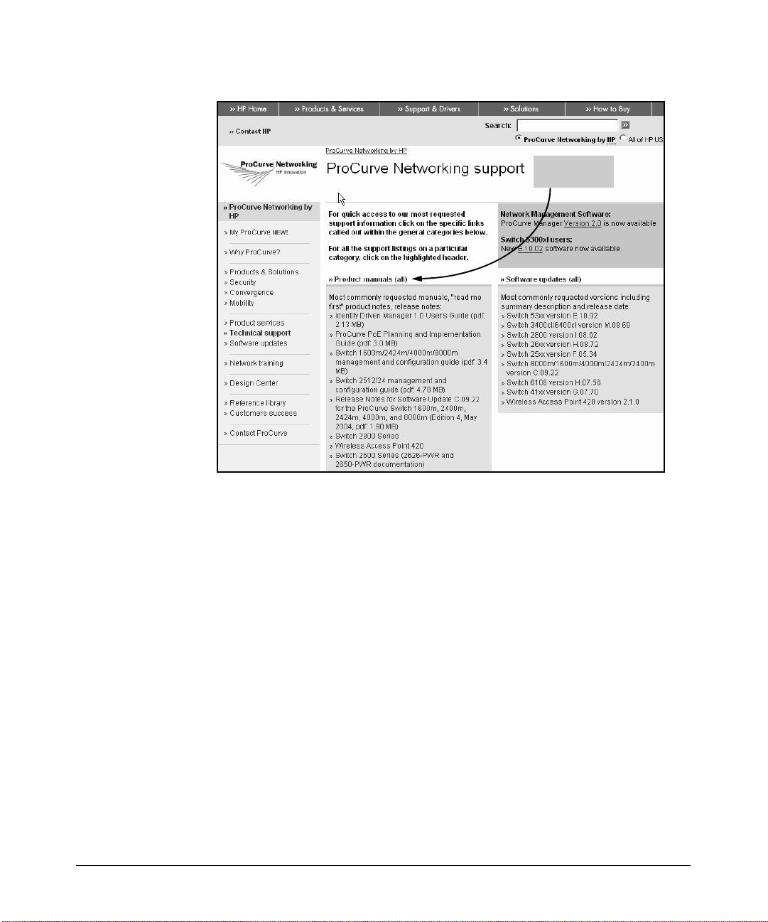
Click Product
Manuals
Overview
Using This Guide
Figure 1-1. The ProCurve Technical Support Web Page
Downloading Software Updates
ProCurve Networking periodically updates the router software to include new
features. You can download software updates and the corresponding release
notes from ProCurve Networking’s Web site as described below.
To download software, complete the following steps:
1. Access the ProCurve Networking Web site at http://www.procurve.com.
2. Click Software updates (in the sidebar). (See Figure 1-2.)
3. Under Latest software, click Secure Router 7000dl Series.
1-7
Page 36
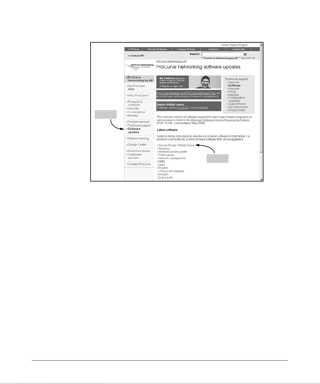
Overview
Using This Guide
Step 2
Step 3
Figure 1-2. Downloading Software Updates
1-8
Release notes are included with the software updates and provide information
about:
■ new features and how to configure and use them
■ software management, including downloading software to the router
■ software fixes addressed in current and previous releases
For information on how to configure basic router functions, see the Basic
Management and Configuration Guide.
Page 37

Interface Management Options
Overview
Interface Management Options
The ProCurve Secure Router includes two management interfaces: the
command line interface (CLI) and the Web browser interface.
CLI
To initially access the CLI, connect the COM port on your workstation to the
console port on the front panel of the router. Use the serial cable (5184-1894)
that was shipped with the ProCurve Secure Router. Then run terminal session
software such as Tera Term or Hyper Terminal on your workstation, and set
up the terminal session with the following parameters:
■ Baud Rate = 9600
■ Parity = None
■ Data Bits = 8
■ Stop Bits = 1
■ Flow Control = None
Using the CLI provides you an organized, linear path to help you configure
your router. This guide will focus primarily on configuring the router through
the CLI.
Web Browser Interface
You can also manage the ProCurve Secure Router through the Web browser
interface, which allows you to navigate the router’s (OS) in a GUI environment.
Even if you are a dedicated CLI user, you should try out this easy-to-use Web
browser interface. You will find it especially helpful for more complicated
tasks such as configuring access control policies (ACPs) and virtual private
networks (VPNs). (See Figure 1-3.) In fact, the Web browser interface provides
wizards to help you configure VPNs, the router’s built-in firewall, or QoS
for VoIP.
1-9
Page 38
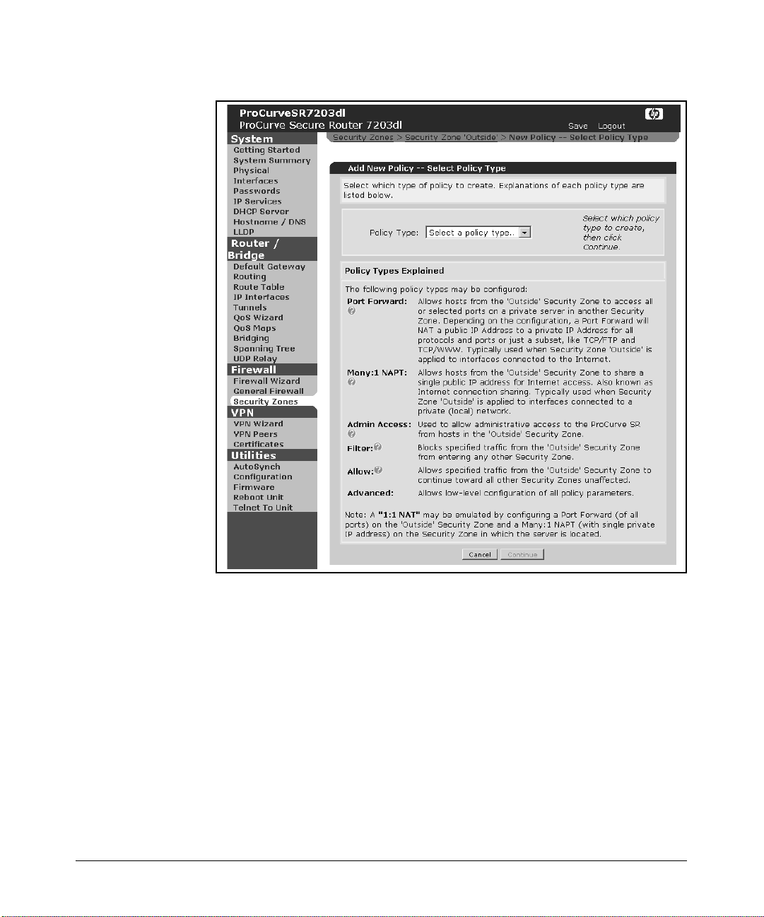
Overview
Interface Management Options
1-10
Figure 1-3. Configuring ACPs Using the Web Browser Interface
Accessing the Web Browser Interface
To access the Web browser interface, you must first establish a CLI session
and configure at least one interface through which you can establish an HTTP
session with the router. You must also enable the HTTP server and configure
a password for HTTP access. For more information on how to configure the
router to access the Web browser interface, see “Configuring HTTP Access”
on page 1-30, or Chapter 14: Using the Web Browser Interface for Advanced
Configuration Tasks.
Page 39

Interface Management Options
Overview
Using the ProCurve Web Browser Interface
The ProCurve Web browser interface is organized into the following sections:
■ System
■ Router/Bridge
■ Firewall
■ VPN
■ Utilities
The System section of the interface contains general router functions. In this
section, you can:
■ configure WAN and LAN connections
■ configure IP services
■ enable the Dynamic Host Configuration Protocol (DHCP) and Domain
Name System (DNS) servers
■ set the router’s hostname and add entries to the DNS host table
■ configure Link Layer Discovery Protocol (LLDP) settings
You can also click Getting Started to display a help menu, or select System
Summary to display information about the router. Click Physical Interfaces
for a list of interfaces (including status and type) on your router.
The Router/Bridge section allows you to configure the router’s bridging and
routing functions. You can set a default gateway, configure the IP interfaces,
set up quality of service (QoS) maps and routing protocols, and add entries to
the route table. You can also configure the router to act as a bridge and
participate in a spanning tree.
The firewall wizard can be found in the Firewall section. Click Firewall
Wizard to open the wizard in a new window. The wizard guides you through
establishing policies for controlling access to your network. From the Fire-
wall section, you can also enable specific application-level gateways (ALGs)
and set protocol timeouts.
The VPN section includes a wizard that simplifies the process of configuring
an IPSec-compliant VPN. The VPN section eliminates the difficulty of remembering the many commands necessary for configuring a VPN in the CLI. The
VPN section only appears in the Web browser interface if you have installed
an optional IPSec encryption module in the rear panel of your router.
You can perform most of your file maintenance in the Utilities section. Click
Configure to complete tasks such as saving, downloading, uploading, and
deleting files. You can also click Firmware to view information about your
1-11
Page 40

Overview
CLI Tools
router’s current OS and upload any necessary upgrades. You can click Reboot
and restart the router, and you can also set up a Telnet session by clicking
Telnet to Unit.
Note In the CLI, boot and configuration files are referred to as software. In the Web
browser interface, the boot and configuration files are called firmware.
For more information on how to configure basic router functioning on your
ProCurve Secure Router using the Web browser interface, see the Basic
Management and Configuration Guide, Chapter 14: Using the Web Browser
Interface for Basic Configuration Tasks.
CLI Tools
This section gives a brief description of the CLI tools and commands that will
help you to configure and troubleshoot your router. If you need more detailed
information on the commands available in the CLI, it is highly recommended
that you consult the Basic Management and Configuration Guide. The Basic
Management and Configuration Guide lists and describes the router’s show
commands, file management commands, and interface configuration commands.
1-12
Help Tools
The Secure Router OS features help tools, editing functions, and global
commands to help you navigate through the Secure Router OS and configure
and maintain your WAN.
CLI Help Commands
You can enter the ? character to help you enter commands in any mode context
in the CLI. The
and options available to those commands in your current router context. You
will not need to press
triggers the display.
■ ?. Entering the ? character displays a list of all the available commands in
your current mode with a brief description of their functions.
? character displays information about the available commands
Enter to activate the ? help tool; the character immediately
Page 41

Overview
CLI Tools
■ letter?. If you know the beginning of a command but need to be reminded
of the entire word or if you want a more limited list of commands, enter
a letter or set of letters followed immediately by the
put a space between the letters and the
?. The router will then display only
? command. Do not
the specific commands that begin with those letters. For example,
ProCurve> e?
enable exception exit
■ command ?. If you know the command but need to be reminded of the
available options, type the command followed by a space and
?. This will
bring up a display of the available options for that command in the current
mode and a brief description of each. For example,
ProCurve(config t1 1/1)#clock source ?
internal -Use internal clock source
line -Recover clock from line
Editing Commands
The router’s CLI supports basic editing functions that can move the cursor
through the command line and allow you to cycle through previous commands. Table 1-1 describes the ProCurve editing commands.
Table 1-1. Keystrokes for Moving Around the CLI
Editing Command Action
Ctrl+p or up arrow recall the most recent command
Ctrl+a move to the beginning of the line
Ctrl+e move to the end of the line
Ctrl+f or right arrow move forward one character
Ctrl+b or left arrow move backward one character
Tab finish partially typed command
Command Recall. Recall the most recent command by entering
pressing the
up arrow. Pressing the up arrow again will cycle through the previous
Ctrl+p or
commands.
Moving within the Command Line. When typing a lengthy command, you
may make an error and need to move the cursor within the command line. See
Table 1-1 for a list of keystrokes that move the cursor within the command line.
1-13
Page 42

Overview
CLI Tools
Tab . The Ta b key is a shortcut of sorts. Press Tab after typing the first few
characters of a command. If you have typed enough characters to distinguish
the command from all other available commands, the Secure Router OS will
finish the word for you.
Truncation. The ProCurve Secure Router OS also recognizes truncated
commands. You only need to enter enough characters in the CLI to distinguish
the command you wish to execute. A good way to tell if you have typed enough
characters is to press the
OS is able to finish the command without having to list possible options, you
have typed enough characters.
For example, when entering the enable mode context, it is not necessary to
type the whole word enable. At the basic mode context prompt there are three
commands that begin with the letter “e” and only one command that begins
with the letters “en.” To enter the enable mode context from basic mode you
only need to enter en and press
typing en at the basic mode context prompt. Because the Secure Router OS
is able to finish the word enable, it completes the truncated command.
Ta b key. If, when you press Ta b, the Secure Router
Enter. This can be checked by pressing Tab after
Basic Commands
This section gives some basic CLI commands that you will need to operate
your router. Only basic commands are described here. For a more comprehensive list and description of router commands, see the Basic Management
and Configuration Guide, Chapter 1: Overview; or the SROS Command Line
Interface Reference Guide.
no
In the enable security mode context, typing the word no before a command
turns off or resets a command option to its defaults. For example, if you want
to stop events notices from displaying to the CLI screen, enter no events.
do
When in the configuration mode context, if you need to execute an enable
mode command, type do before you enter the command. The do command
allows you to stay in your current mode context while executing a command
that is usually only available in the enable mode context. You will most often
use this command with show commands. For example, to display the status
of an interface while configuring a protocol interface, enter:
Syntax: do show interface <interface type> <slot>/<port>
ProCurve(config-ppp 1)# do show interface e1 1/1
1-14
Page 43

Overview
CLI Tools
exit
To leave a specific interface or configuration mode, type exit. The exit
command moves you back one mode level. For example, if you were configuring an ATM interface in the ATM interface configuration mode context and
entered exit when you were finished, you would return to the global configuration mode context.
When you enter the exit command in the global configuration mode context
and return to the enable mode context, the CLI displays this message:
Appropriate commands must be issued to preserve configuration.
This message is a reminder to save the configuration you have completed. All
configuration changes are initially saved only in the router’s running-configuration file, which is stored in flash memory. If the router were powered down,
the running config, and any changed that you have not saved, would be lost.
The next section describes the file management commands you need to save
your configuration.
File Management Commands
This section describes the basic file management commands that allow you
to save your configurations, copy files from the router to another medium, or
erase files from your router’s flash or compact flash memory.
The router has two configuration files that keep track of the router’s settings:
startup-config and running-config. The router uses the startup-config file as a
map to setup the router’s configuration during the boot process. This file
contains saved configuration settings and is used to configure the router when
it is powered on and boots.
As you make configuration changes, the router stores these configuration
changes in the running-config file, which is stored in the routers RAM memory.
Only the currently running and implemented configurations are stored in
running-config. This file is lost when the router powers down. If you want to
keep the configuration changes you have made to the router, you must save
this file, as described in the following sections.
copy
This command has the following syntax:
Syntax: copy <source file location> <filename> <destination location> <destination
filename>
1-15
Page 44

Overview
CLI Tools
This command is used to copy and save files in the router’s internal flash and
compact flash memories. Table 1-2 gives the available options for the copy
command.
You can also use this command to save the changes you make in the runningconfig to the startup-config. If you do not save these changes, the next time
the router reboots, any changes will be lost.
To save configuration changes while using the CLI, enter:
Syntax: copy running-config [<destination location> <destination filename> |
<config-file>]
ProCurve# copy running-config startup-config
Table 1-2. Options for the copy Command
Source Location Options Destination Location Options
cflash <filename> or
flash <filename>
cflash or flash • tftp
console • flash <filename>
running-config • cflash <filename>
startup-config • cflash <filename>
tftp or xmodem • flash
•boot
• cflash [<filename>]
• flash [<filename>]
• interface (only from flash <filename>)
•xmodem
• flash <filename>
• startup-config
• tftp
•xmodem
• flash <filename>
• running-config
• tftp
•xmodem
• cflash
• running-config
• startup-config
1-16
Ver ify that th e Done. Success! message is displayed, indicating that the copy
process is complete.
Page 45

Overview
CLI Tools
To save a configuration as a file on compact flash, enter the following command from the enable mode context:
Syntax: copy flash <config-file> cflash <filename>
Replace <config-file> with either running-config or startup-config and
replace <filename> with a name that you choose.
Ver ify t hat t he Percent Complete 100% message is displayed, indicating that
the download is complete. The current configuration is now saved in compact
flash with the specified filename.
To save a configuration as a file on internal flash, enter the following command
from the enable mode context:
ProCurve# copy <source file location> <source config-file> flash [<filename>]
Replace <source file location> with the location of the configuration file
you are saving. Replace <source config-file> with startup-config or run-
ning-config. You must enter a destination filename unless the filename will
be the same as that of the source. For example, if you need to save the startupconfig file from the compact flash card to internal flash, enter:
ProCurve# copy cflash startup-config flash startup-config
Saving the Current or Start-up Configuration to a TFTP Server. To
initiate an upload of a configuration file to an external TFTP server, enter one
of the following commands from the enable mode context:
ProCurve# copy [flash | cflash] tftp
ProCurve# copy [startup-config | running-config] tftp
For example, if you wanted to upload the startup-config on compact flash to
your TFTP server, you would enter:
ProCurve# copy cflash tftp
When prompted for the Address of remote host?, enter the IP address of
the TFTP server.
When prompted for the Source filename?, enter the name of the configuration file (startup-config or running-config) you would like to upload.
When you are prompted for the Destination filename?, enter the filename
you’d like the uploaded configuration file to be named.
1-17
Page 46

Overview
CLI Tools
The copy command can be used for other file TFTP management tasks
such as:
■ loading a running-configuration file from the TFTP server—Enter copy
tftp running-config.
■ loading a startup-configuration from the TFTP server—Enter copy tftp
startup-config.
erase
The erase command removes files from the specified file location.
Syntax: erase <file location> <filename>
For example, entering erase flash <filename> will delete the file you specify
from internal flash:
ProCurve# erase flash oldconfig
This command also allows you to erase files from compact flash:
ProCurve# erase cflash config1.cfg
write
This command is similar to the copy and erase commands.
Entering write memory will save the running-configuration to the startupconfiguration. In J03_01.biz and later, this file will automatically save to the
compact flash card, if present. Otherwise the startup-config file will be saved
on the router’s internal flash.
Entering write erase deletes the startup-config file. If you have a compact
flash card, the startup-config is erased from cflash. If you are running the
AutoSynch™ function, this command erases startup-config from both flash
and compact flash. If you do not have a compact flash card, the file is erased
from flash.
The write network command saves the running config to a TFTP server. You
can set the filename to something meaningful to you when you are prompted
with Destination filename?.
The write terminal command is similar to the show running-config
command; it displays the current running-configuration in the CLI.
1-18
Page 47

Overview
CLI Tools
autosynch
The autosynch command is used with a compact flash card. Enabling the
AutoSynch™ function allows the router to automatically keep the startupconfig and SROS files in internal flash synchronized with the startup-config
and SROS file on the compact flash card.
The autosynch command is disabled in its default setting. To enable the
AutoSynch™ technology, enter the global configuration mode and enter:
ProCurve (config)# autosynch-mode
AutoSynch: SROS.BIZ synched
AutoSynch: startup-config synched
To disable AutoSynch™, use the no command:
ProCurve(config)# no autosynch-mode
AutoSynch: SROS.BIZ not synched
AutoSynch: startup-config not synched
For more information on file management and router boot functioning, please
see the Basic Management and Configuration Guide, Chapter 1: Overview.
Troubleshooting Commands
The following commands are some basic commands to help with troubleshooting router operation.
reload in
When you are configuring the ProCurve Secure Router through a Telnet, SSH,
or Web session, you may want to enter a safeguard to ensure that you do not
inadvertently block your access to the router. You can configure the ProCurve
Secure Router to reload the startup-config at a specified future time, returning
the router to its previous configurations.
To schedule a system reboot, enter the following command from the enable
mode context:
ProCurve# reload in <mmm>
or
ProCurve# reload in <hhh:mm>
1-19
Page 48

Overview
CLI Tools
Replace <mmm> with the number of minutes. You can specify a three-digit
number. Replace <hhh:mm> with a time such as 1:15 (1 hour and 15 minutes).
The CLI will prompt you to save the system configuration. If you have already
made the configurations that you want to test, reply no. If you are getting ready
to make the configurations to be tested and want to save previous configurations, reply yes. The CLI then displays:
You are about to reboot the system. Continue? [y/n]
Enter
y. The system will not reboot immediately. It will wait the amount of time
you have specified. Remember that you must not save the running-config to
the startup-config (by entering either write mem or copy run start) while
you are configuring the router. Otherwise, the ProCurve Secure Router will
load these configurations when it reboots.
To cancel the reload, enter:
ProCurve# reload cancel
show
The show commands are only available in the enable mode context or by using
the do command. These commands allow you to check the router’s configured
settings by displaying router functionality information in the CLI. This allows
you to find miskeyed commands or problem configurations and repair them.
Individual show commands are described throughout this book and the Basic
Management and Configuration Guide. For a more detailed list and explanation of the available show commands, see the Basic Management and
Configuration Guide, Chapter 1: Overview.
1-20
show tech
Unlike the other show commands, the show tech command does not display
the information in the CLI. This command creates a file named showtech.txt
in flash that contains a summary of the router’s show command information.
To create this file enter show tech at the enable mode context prompt. This
will prepare a showtech.txt file and save it in the router’s internal flash.
After the showtech.txt file is created, you can save it to compact flash or
upload it to a TFTP server. You can also save the contents of the showtech.txt
file to your terminal’s text editor. See “Managing Configuration Files Using a
Text Editor” on page 1-24 for more information on how to manage files with
a text editor.
Page 49

Overview
CLI Tools
Note The showtech.txt file is saved to internal flash. If you intend to use a compact
flash card to transport the file, you must save the showtech.txt file to a
compact flash card.
The showtech.txt file contains a readout of many of the show commands. This
readout allows a network administrator to pinpoint a router configuration
problem without a connection to the router. To display the contents of the
showtech.txt file, enter show file flash showtech.txt from the enable mode
context.
To have the router display the show tech readout without creating or saving
a showtech.txt file, use the terminal option:
Syntax: show tech terminal
ProCurve# show tech terminal
safe-mode
SafeMode is a CLI feature that allows you to perform configuration changes
without the fear of being disconnected from a Telnet or SSH session. Some
configuration changes can interrupt network connectivity. If you are
managing a router remotely via SSH or Telnet, you can inadvertently lose your
connection to the router.
For example, you may need to apply an ACL, but this ACL doesn’t allow Telnet
or SSH traffic. Once you applied the ACL, you would be locked out of the
router. In order to fix the configuration that has locked you out, you would
need physical access to the router so that you could establish a console session
with it. SafeMode allows you to make configuration changes using Telnet or
SSH without worrying about losing your connection and being unable to
reestablish it.
SafeMode requires you to periodically reset a reload timer. If the reload timer
runs out before you reset it, the Secure Router OS will assume that the current
running configuration has disrupted your connection to the router. It will save
the running-config to internal flash as “problem-config” and reboot the router.
Once the router has reloaded, it will display a reboot cause message and load
the currently saved startup-configuration file. The startup-config should allow
you to regain access to the router. You will then be able to review the saved
problem-config file and correct the setting that caused the disruption.
After you enable SafeMode and set the time limit, a reload timer is activated
for the Telnet and SSH access lines and begins to count down. You also set a
threshold timer, which is shorter than the reload timer. When the threshold
1-21
Page 50

Overview
CLI Tools
timer expires, a warning message is displayed in the CLI that allows you to
reset the timer. Unless you enter the reset keystroke before the reload timer
finishes counting down, the router reboots. This prevents you from being
locked out of the router if you lose the connection and are unable to reset the
timer.
While SafeMode is enabled, it temporarily suspends the AutoSynch™
function. This prevents a disruptive configuration from being saved to both
flash and compact flash. After the SafeMode configuration is complete and
you have disabled the SafeMode counter, the autosynch command, if
previously enabled, will automatically reenable and begin synchronization.
Enabling SafeMode. To enable SafeMode, access the global configuration
mode context and enter:
Syntax: safe-mode [<reload time> <threshold time>]
For example:
ProCurve(config)# safe-mode 600 500
ProCurve(safe-config)#
Set the <reload time> to the number of seconds to countdown until the
router reboots. Set the <threshold time> to the number of seconds to
countdown until you receive a reminder to reset the timer. Both the reload
time and threshold time must be between 30 and 3600 seconds. The default
value for the reload time is 300 seconds, and the default value for the threshold
time is 60 seconds. To enable SafeMode with the default settings, enter safe-
mode at the global configuration prompt.
1-22
The reload time should be greater than the threshold time. If you enter a
threshold value greater than the reload value, the CLI displays an error
message.
When you are configuring in SafeMode from a Telnet or SSH session, the
configuration mode context prompt is displayed as safe-config. For example:
ProCurve(safe-config)# interface ethernet 0/1
ProCurve(safe-config-eth 0/1)#
All configurations that you make during SafeMode are saved in RAM as part
of the running-config.
After the countdown for the reload timer has begun, it continues until you
either reset it by pressing
Ctrl+R, you disable it by entering no safe-mode, or
you exit out of the global configuration mode context.
Page 51

Overview
CLI Tools
Use the no form of the command to disable SafeMode and the countdown
timer:
ProCurve(safe-config)# no safe-mode
ProCurve(config)#
SafeMode Functioning. SafeMode events are displayed in the CLI. When
the threshold timer reaches zero, a notice is displayed in the CLI reminding
you to reset the timer:
SAFEMODE: SafeMode will reboot in <threshold> seconds.
When you activate SafeMode, or when you leave and re-enter the configuration
mode context while SafeMode is enabled, the reload timer is activated and a
message is displayed in the CLI:
SAFEMODE: SafeMode enabled. Reboot in <n> seconds!
Once SafeMode is enabled, any CLI user can reset the timer by entering
Ctrl+R.
You can reset the timer at any time, as often as you need to complete the
configuration.
Caution If you save your configuration to the startup-config while in SafeMode, you
may essentially negate SafeMode’s effect: the rou ter may reboot with the saved
disruptive configuration and you will still be locked out of the router. Be very
careful about saving your in-process configurations when in SafeMode.
The problem-config file that is generated when the router reboots can be
examined and edited in a text editor to repair the commands that caused the
problems.
Note The problem-config file is saved in the router’s internal flash memory. If you
want to transport the file or save a backup of the file using compact flash, you
need to copy the file to compact flash by entering copy flash problem-config
cflash problem-config from the enable mode context.
1-23
Page 52

Overview
Managing Configuration Files Using a Text Editor
Managing Configuration Files Using a
Tex t Editor
Configuration files can be adjusted to each router’s needs using your computer’s text editor. This allows you to set up a configuration on one router,
save it to a file, and edit it for installation on another router.
Begin creating a configuration file by creating a base configuration on an
originating router. Save the base configuration and impo rt it—using a compact
flash card, the router’s console, or a TFTP server—to a terminal with a text
editor. The readout of the configuration file will resemble the readout of the
running-config for the router (displayed by entering show run at the enable
mode context prompt). Once you have pasted this text into the text editor,
you can adjust the IP address, hostname, ACLs and ACPs, and other configuration concerns to prepare the file for the target router. These adjustments are
made by simply typing in the desired command or value using the format
displayed in the file readout. Then move the file to the target router and save
it as the startup-config. Reboot the router using the reload command and the
router will boot with the new configuration.
1-24
Using Error Messages to Repair a Configuration
The ProCurve Secure router configuration files are robust. If you miskey a
command or make a mistake in the text editor, the router will simply ignore
the mistake and use the default settings. If any necessary command is missing,
the router will simply substitute the default. Problem commands will trigger
an error message during bootup.
If you do have a problem command that is running on its default setting, it is
not necessary to re-edit the configuration in a text editor. To repair the
problem, simply enter the pertinent command in the CLI. Use the error
messages displayed during bootup to determine which command is faulty.
Page 53
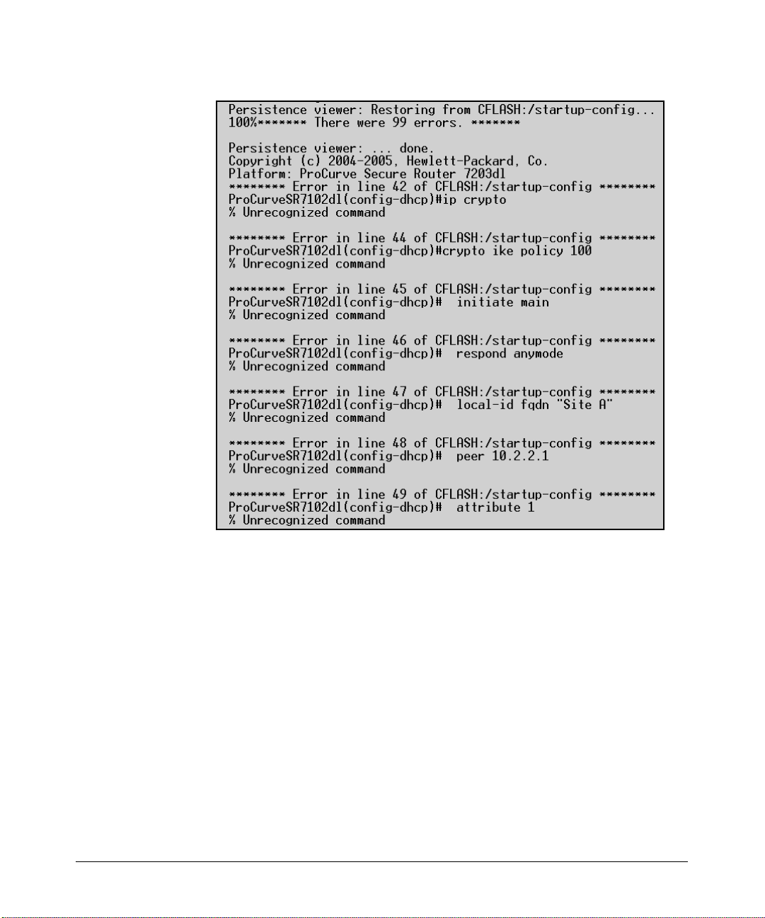
Managing Configuration Files Using a Text Editor
Overview
Figure 1-4. Boot Error Messages
The error messages in Figure 1-4 were displayed during bootup. In this
particular case, the startup-config file has several VPNs configured, and the
router that is booting does not have an IPSec VPN module to support it. The
commands for the configuration of the VPNs are reported as errors.
Use error messages like these to locate and troubleshoot the problem in the
router’s configuration.
1-25
Page 54
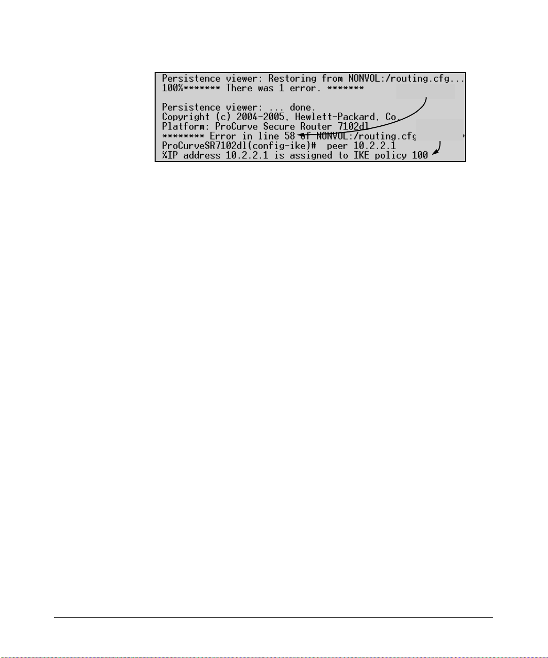
Overview
Managing Configuration Files Using a Text Editor
Figure 1-5. Using Boot Error Messages to Target a Configuration Problem
The line number given in the error message is the line number in the runningconfig. You can use this information to repair any configuration problems.
You will need to scroll up in your terminal session software window to read
the error message. Make a note of the reported line number, the command,
and the resulting error message, as shown in Figure 1-5. Then return to the
command line and enter the enable mode context.
Enter show running-config to display the current configuration. When the
running-config is displayed, begin with the first exclamation point and count
down, line by line, until you reach the line that generated the error message.
Check the resulting message from the error report. Repair the problem by reentering the command on that line using the error report as a guide.
Error location
Resulting
message
1-26
For example, in Figure 1-5, there is an error in line 58. The faulty command was
ProCurve(config-ike)# peer 10.2.2.1
The peer at 10.2.2.1 was already assigned to IKE policy 100 and cannot be
assigned to more than one policy. In this example, the IKE policy configurations may need to be adjusted.
Page 55

Overview
Quick Start
Quick Start
This section provides the instructions you need to quickly access the ProCurve
Secure Router CLI and configure an enable mode password to protect the
router from unauthorized access. This section also explains how to configure
the Ethernet interface and the HTTP server so that you can access the Web
browser interface. You will then be able to manage the ProCurve Secure
Router through an Internet browser.
Only minimal explanation is provided. It is strongly recommended that you
read the entire chapter so that you understand how the Secure Router operating system (OS) is organized and how to manage the OS. If you need
information about a specific aspect of managing the OS, see the Basic Man-
agement and Configuration Guide to locate the section that contains the
explanation you need.
Accessing the Secure Router OS
1. Use the serial cable (5184-1894) that shipped with the ProCurve Secure
Router to connect the COM port on your laptop to the console port on the
front panel of the router.
2. Open a terminal session with the ProCurve Secure Router, using the
following settings:
• Baud Rate = 9600
• Parity = None
• Data Bits = 8
• Stop Bits = 1
• Flow Control = None
3. Press
4. Access the enable mode context:
5. Access the global configuration mode:
Enter to access the basic mode context.
ProCurve> enable
ProCurve# configure terminal
1-27
Page 56

Overview
Quick Start
Configuring the Enable Mode Password
6. Configure an enable mode password.
Syntax: enable password [md5] <password>
Enter the md5 option to encrypt the password. Replace <password>
with an alphanumeric string of up to 16 characters.
For example, you might enter:
ProCurve(config)# enable password md5 ProCurve
Note The word ProCurve is shown as the password only for simplicity. In a
production environment, you should follow the standard guidelines for creating a password that cannot be easily guessed by unauthorized users. In
addition, you should avoid writing the password down and posting it where
others can read it.
Configuring the Ethernet Interface
1. Use a 10Base-T or 100Base-T cable to connect the Ethernet port on the
ProCurve Secure Router to the appropriate device on your LAN. In most
cases, you will connect the router to a core switch.
1-28
2. Access the configuration mode context for the Ethernet interface.
Syntax: interface ethernet 0/<port>
For example, if you want to configure the bottom Ethernet port, enter:
ProCurve(config)# interface ethernet 0/1
3. Assign the Ethernet interface an IP address.
Syntax: ip address <A.B.C.D> <subnet mask | /prefix length>
For example, if you want to assign the Ethernet interface an IP address
of 192.168.115.1 /24, enter
ProCurve(config-eth 0/1)# ip address 192.168.115.1 /24
4. Activate the Ethernet interface.
ProCurve(config-eth 0/1)# no shutdown
A message should be displayed at the CLI, reporting that the interface is
“administratively up.” In a few moments, another message should be
displayed reporting that the interface is up. (If this message does not
appear, you can find troubleshooting information in the Basic
Management and Configuration Guide, Chapter 3: Configuring
Ethernet Interfaces.)
Page 57

Overview
Quick Start
Configuring Telnet Access
After you configure an Ethernet interface and establish a connection to the
ProCurve Secure Router, you can configure Telnet access to the router.
Complete the following steps:
1. Establish a console session to the ProCurve Secure Router and move to
the global configuration mode context.
ProCurve# configure terminal
2. Enter the following command to access the Telnet line configuration
mode context:
Syntax: line telnet [0-4]
The ProCurve Secure Router supports five lines. Enter the number of the
line you want to configure. If you want to enable all five lines, enter:
ProCurve(configure)# line telnet 0 4
3. Create the Telnet password
Syntax: password [md5] <password>
Enter the md5 option to encrypt the password. Replace <password>
with an alphanumeric string of up to 16 characters.
For example, you might enter:
ProCurve(config-telnet0)# password md5 en$ter^tel
4. Exit to the global configuration mode context.
ProCurve(config-telnet0)# exit
5. Configure an enable mode password, if you have not done so already. The
enable mode password is required for Telnet access.
Syntax: enable password [md5] <password>
Enter the md5 option to encrypt the password. Replace <password>
with an alphanumeric string of up to 30 characters.
Configuring SSH Access
After you configure an Ethernet interface and establish a connection to the
ProCurve Secure Router, you can establish SSH access to the router. By
default, SSH access to the ProCurve Secure Router is enabled. After you have
set an enable mode password, you simply need to configure a username and
password.
1-29
Page 58

Overview
Quick Start
Complete the following steps:
1. Establish a console session to the ProCurve Secure Router and move to
the global configuration mode context.
ProCurve> enable
ProCurve# configure terminal
2. If you have not already done so, configure an enable mode password.
Enter:
Syntax: enable password <password>
3. Configure a username and password for SSH access. The username and
password you enter can be used for FTP and HTTP access as well.
Syntax: username <username> password <password>
Replace <username> and <password> with an alphanumeric string of
up to 30 characters.
Configuring HTTP Access
1. Enter the global configuration mode context.
2. Enable the HTTP server on the router.
ProCurve(config)# ip http server
3. If you have not already done so, configure a username and password for
the HTTP server. The username and password also secure FTP and SSH
access to the router.
Syntax: username <username> password <password>
4. Return to the enable mode context and save your configuration.
ProCurve(config)# exit
ProCurve# write memory
1-30
Page 59

Increasing Bandwidth
Contents
Overview . . . . . . . . . . . . . . . . . . . . . . . . . . . . . . . . . . . . . . . . . . . . . . . . . . . . . . 2-2
Configuring MLPPP . . . . . . . . . . . . . . . . . . . . . . . . . . . . . . . . . . . . . . . . . . . . . 2-3
PPP . . . . . . . . . . . . . . . . . . . . . . . . . . . . . . . . . . . . . . . . . . . . . . . . . . . . . . . 2-4
MLPPP . . . . . . . . . . . . . . . . . . . . . . . . . . . . . . . . . . . . . . . . . . . . . . . . . . . . 2-5
LCP Options . . . . . . . . . . . . . . . . . . . . . . . . . . . . . . . . . . . . . . . . . . . . 2-5
MLPPP Header . . . . . . . . . . . . . . . . . . . . . . . . . . . . . . . . . . . . . . . . . . 2-5
MLPPP Configuration Concerns . . . . . . . . . . . . . . . . . . . . . . . . . . . 2-6
Enabling MLPPP . . . . . . . . . . . . . . . . . . . . . . . . . . . . . . . . . . . . . . . . . . . . 2-6
Binding Multiple Carrier Lines to a PPP Interface . . . . . . . . . . . . . . . . 2-6
Configuring MLFR . . . . . . . . . . . . . . . . . . . . . . . . . . . . . . . . . . . . . . . . . . . . . . 2-8
Enabling MLFR . . . . . . . . . . . . . . . . . . . . . . . . . . . . . . . . . . . . . . . . . . . . . 2-9
Binding Multiple Carrier Lines to a Frame Relay Interface . . . . . . . . 2-10
Configuring the Bundle ID . . . . . . . . . . . . . . . . . . . . . . . . . . . . . . . . . . . 2-11
2
Troubleshooting Multilinks . . . . . . . . . . . . . . . . . . . . . . . . . . . . . . . . . . . . . . 2-12
Standard Procedure . . . . . . . . . . . . . . . . . . . . . . . . . . . . . . . . . . . . . . . . 2-12
Physical Layer . . . . . . . . . . . . . . . . . . . . . . . . . . . . . . . . . . . . . . . . . . 2-12
Data Link Layer . . . . . . . . . . . . . . . . . . . . . . . . . . . . . . . . . . . . . . . . 2-12
Troubleshooting MLPPP . . . . . . . . . . . . . . . . . . . . . . . . . . . . . . . . . . . . 2-15
MRRU . . . . . . . . . . . . . . . . . . . . . . . . . . . . . . . . . . . . . . . . . . . . . . . . 2-15
ED . . . . . . . . . . . . . . . . . . . . . . . . . . . . . . . . . . . . . . . . . . . . . . . . . . . 2-16
Troubleshooting MLFR . . . . . . . . . . . . . . . . . . . . . . . . . . . . . . . . . . . . . . 2-16
Quick Start . . . . . . . . . . . . . . . . . . . . . . . . . . . . . . . . . . . . . . . . . . . . . . . . . . . . 2-19
MLPPP Configuration . . . . . . . . . . . . . . . . . . . . . . . . . . . . . . . . . . . . . . . 2-20
MLFR Configuration . . . . . . . . . . . . . . . . . . . . . . . . . . . . . . . . . . . . . . . . 2-21
2-1
Page 60

Increasing Bandwidth
Overview
Overview
Point-to-Point Protocol (PPP) and other Data Link Layer protocols establish
point-to-point connections over a single carrier line, which may not provide
sufficient bandwidth to meet a business’s requirements. In a Frame Relay
network, a single Frame Relay port might carry several permanent virtual
connections (PVCs), all of which must share the bandwidth provided by one
carrier line. If a WAN line has inadequate bandwidth, it can become congested
and packets can be dropped.
Purchasing a high-bandwidth E3- or T3-carrier line to sidestep these limitations is not always feasible because some environments do not support them.
In addition, E3- or T3-carrier lines can be quite expensive, and you may not
need the high-bandwidth they provide. Your organization may only need to
double or triple its bandwidth, rather than increase it 28 fold. You cannot
justify the high-cost of an E3- or T3-carrier line when much of the bandwidth
will go unused.
The ProCurve Secure Router supports link-aggregation protocols to address
these problems. Such protocols treat multiple carrier lines as a single bundle,
providing two advantages:
■ Faster connections—Traffic can access the combined bandwidth of
the bundle.
■ More stable connections—If one line goes down, the other can still
carry traffic.
2-2
Theoretically, link aggregation is a simple idea: effectively double your available bandwidth by using two physical cables to connect your endpoints
instead of only one, triple your bandwidth by using three cables, quadruple
your bandwidth by using four cables, and so on. For example, you could
aggregate two 1.544-Mbps T1-carrier lines into a virtual single network connection with an underlying bandwidth of 3.088 Mbps.
The ProCurve Secure Router supports these link-aggregation protocols:
■ Multilink PPP (MLPPP)
■ Multilink Frame Relay (MLFR)
Link-aggregation protocols such as MLPPP and MLFR take advantage of
multiple physical cables by fragmenting frames into smaller frames. These
fragments are passed simultaneously over separate cables and then reassembled by the receiving peer. (See Figure 2-1.)
Page 61
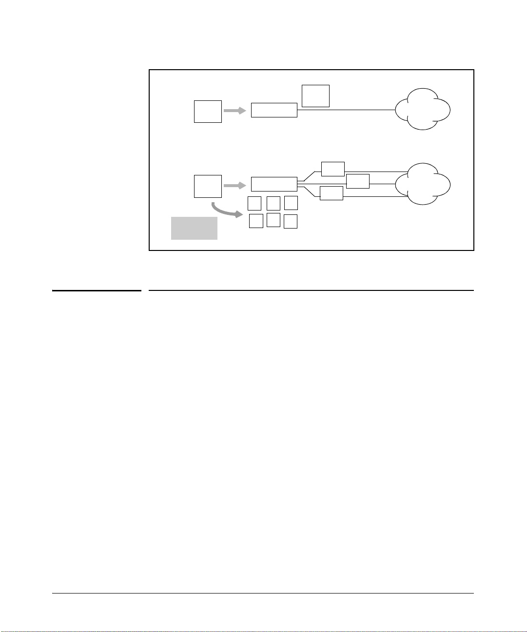
PPP
PPP
Frame
Increasing Bandwidth
Configuring MLPPP
PPP
Frame
Router
E1 Line
MLPPP
PPP
Frame
Frame
fragments
Router
a b
d
c
e
f
Frag a
Frag d
Frag c
E1 Lines
Figure 2-1. MLPPP, a Link Aggregation Protocol
Configuring MLPPP
Although using MLPPP to increase a connection’s bandwidth does not require
deep technical expertise, you should understand:
■ how a PPP session is established
■ how MLPPP regulates the fragmentation and reconstruction of normal
PPP frames
Such an understanding will help you troubleshoot MLPPP connections and
regulate data flow.
2-3
Page 62
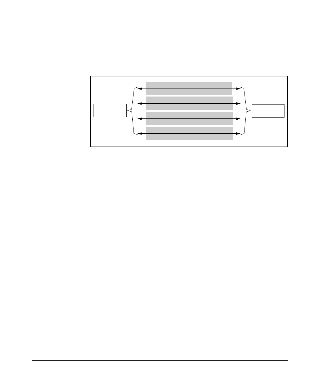
Increasing Bandwidth
Configuring MLPPP
PPP
The two peers at either end of a point-to-point connection establish a PPP
session in four phases. (See Figure 2-2.)
1. Link establishment
LCP
2. Authentication (optional)
ProCurve
Secure Router
3. Negotiation of Network Layer protocols
Figure 2-2. PPP Phases
1. Link establishment—Peers exchange Link Control Protocol (LCP) frames
to establish a link and negotiate the options for this link. These options
include the maximum receive unit (MRU), which determines the size of
the informational field in PPP frames, and the authentication protocol, if
used.
PAP, CHAP, or EAP
NCP: IPCP, BCP, and so on
4. Session established
PPP
ProCurve
Secure Router
2-4
2. Authentication—Peers exchange frames for the authentication protocol
agreed upon during link establishment. (If they did not select authentication, they proceed to the next stage.) After both peers authenticate
themselves successfully, they proceed to the next stage.
3. Network Layer protocol—Peers exchange Network Control Protocol
(NCP) frames to negotiate which Network Layer (Layer 3) protocol the
PPP frames will encapsulate. NCP frames serve two functions: they
specify which Network Layer protocol will be used, and they negotiate
options for that protocol. For example, IP Control Protocol (IPCP) is the
NCP for IP. An IPCP frame can include IP addresses for DNS servers and
a request to compress the IP datagram (which will be the PPP information
field).
4. PPP—PPP frames carry the actual information being transferred over
the WAN link. In PPP terminology, this information is called a datagram.
After the two peers successfully exchange LCP frames, authenticate the
link (if authentication is configured), and negotiate the Network Layer
protocol, a PPP session is established. The peers can then exchange PPP
datagrams.
Page 63

Increasing Bandwidth
Configuring MLPPP
MLPPP
MLPPP establishes a session between two peers using the same protocols and
phases as typical PPP. However, MLPPP adds:
■ three option fields to the LCP frames
■ an MLPPP header to the information field of the PPP frame
LCP Options
The receiving peer must know that the sending peer will be fragmenting PPP
frames and transmitting them over multiple carrier lines. The receiving peer
must also be able to recognize that these fragmented frames originate from a
single peer. Three LCP options prepare peers to exchange PPP frames over
an MLPPP connection:
■ Maximum Receive Reconstructed Unit (MRRU)—The MRRU option
serves two functions: it indicates that the sending peer wants to, and that
the receiving peer can, use MLPPP, and it specifies the size of the reconstructed frame (replacing the MRU).
■ Short Sequence Number Header Format—A peer can request to use a 12-
bit rather than a 24-bit sequence number in the MLPPP header. A 12-bit
sequence number enables a frame to be split into a little less than 5,000
fragments, which is more than adequate for the typical bundle of lines.
■ Endpoint Discriminator (ED) options—Peers negotiate how the receiving
peer will identify the sending peer. One of these methods is an ED, which
can be generated from an IP address, media access control (MAC)
address, or PPP magic number. Every carrier line in the MLPPP bundle
originates from the same endpoint and is given the same ED. The receiving
peer recognizes that frames received from different carrier lines, but with
the same ED, come from the same peer.
MLPPP Header
The MLPPP header helps the receiving peer reconstruct frame fragments in
the correct order. When a peer sends a PPP frame across a multilink point-topoint connection, it first fragments the PPP frame. It then encapsulates
fragments in new PPP frames and sends them simultaneously over each
aggregated line. The new PPP frame includes:
■ a new PPP header
■ a four-field MLPPP header
■ a fragment of the original PPP frame
2-5
Page 64

Increasing Bandwidth
Configuring MLPPP
If peers agreed to use the short sequence number header format during the
link establishment, the MLPPP header includes only two fields.
The MLPPP header includes a flag and a sequence number. The sequence
number indicates the fragment’s place in the reconstructed PPP frame.
MLPPP Configuration Concerns
When you enable MLPPP for a connection, the LCP automatically negotiates
the necessary options, such as the MRRU and ED. You simply need to bind the
extra carrier lines to the PPP interface. MLPPP automatically adds the lines
to the bundle.
Carrier lines send keepalive signals. MLPPP automatically removes lines that
go down from the bundle and adds lines that come back up. The PPP connection stays open as long as at least one line is good.
Enabling MLPPP
Identify the PPP interface for the connection whose bandwidth you want to
increase. Move to the configuration mode context for this interface and enable
multilink:
2-6
ProCurve(config)# interface ppp 1
ProCurve(config-ppp 1)# ppp multilink
Binding Multiple Carrier Lines to a PPP Interface
On the ProCurve Secure Router, links are always defined by the Data Link
Layer (for example, a PPP interface), rather than by the Physical Layer. You
bind a physical interface to a logical interface to grant the Data Link Layer
protocol access to the physical media over which to transmit data. This way
of defining links makes configuring MLPPP easy: you simply bind more than
one carrier line to the same PPP interface.
You can bind as many carrier lines to the PPP interface as are installed on the
router. The ProCurve Secure Router 7102dl provides up to 4 E1- or T1-carrier
lines, and the ProCurve Secure Router 7203dl provides up to 12 E1- or T1carrier lines, depending on the modules that you purchase.
Page 65

Increasing Bandwidth
Configuring MLPPP
You should have already configured the physical interfaces. If you have not,
see the Basic Management and Configuration Guide, Chapter 4: Configur-
ing E1 and T1 Interfaces for instructions. To bind these interfaces to the PPP
interface, you need the following information:
■ type of carrier line (E1 or T1)
■ dl module slot for the carrier line’s module
■ port number for the interface to which the line connects
■ time division multiplexing (TDM) group number
The TDM group number defines the range of channels used by an E1- or T1carrier line. The carrier lines that will be aggregated can use the same or a
different TDM group number, but these groups must use the same number of
channels.
You can enter the bind command either from the global or the PPP interface
configuration mode contexts:
Syntax: bind <bind number> [e1 | t1] <slot>/<port> <tdm group number> ppp
<interface number>
Use a different bind number for each carrier line you want to bundle. For
example, you might enter:
ProCurve(config)# bind 1 e1 1/1 1 ppp 1
ProCurve(config)# bind 2 e1 1/2 1 ppp 1
ProCurve(config)# bind 3 e1 2/1 1 ppp 1
2-7
Page 66

Increasing Bandwidth
Configuring MLFR
Configuring MLFR
Like MLPPP, MLFR aggregates several physical connections into a single
logical connection. MLFR helps provide greater access rates for PVCs, particularly in environments in which the greater bandwidth of an E3- or T3-carrier
line is not available. MLFR also creates more stable PVCs: if one physical
interface goes down, the other interfaces can continue to provide bandwidth
for a connection.
Routers that support MLFR FRF.15 bundle multiple carrier lines at the user’s
end. The service provider does not recognize the bundle. It assigns each line
one Data Link Connection Identifier (DLCI) and carries traffic over the PVC
for each line, just as it would for non-bundled lines. The remote router, which
also runs MLFR FRF.15, receives the traffic from multiple PVCs but treats it
as traffic from a single PVC.
FRF.15 does not require the Frame Relay service provider to support MLFR.
However, each bundle can support only one point-to-point connection to a
remote site. The remote site must use the same number of carrier lines as the
local site.
2-8
The ProCurve Secure Router supports MLFR FRF.16 rather than FRF.15,
which means that your service provider must support MLFR. FRF.16 provides
several advantages over FRF.15. It allows a bundle to carry multiple PVCs to
multiple remote sites, and these sites can use different amounts of bandwidth.
FRF.16 aggregates multiple carrier lines to produce a high-speed connection
to the Frame Relay service provider. The service provider supports MLFR, so
it recognizes that these lines should be treated as a single bundle. The service
provider assigns you a DLCI for the lines as a bundle instead of for each line
individually. Rather than associating DLCI 101 with E1-carrier line 1 and DLCI
102 with E1-carrier line 2, the Frame Relay service provider associates DLCI
101 and 102 with both E1-carrier lines. (See Figure 2-3.)
You can request DLCIs for PVCs to as many remote sites as your organization
needs. In addition, the remote sites do not have to aggregate the same number
of lines as the local site or even run MLFR at all. The multilink connection is
to the Frame Relay provider, not to the remote sites.
MLFR does not necessarily fragment frames. However, it can use FRF.12 to
fragment large frames and minimize delay. An MLFR header is added to the
original Frame Relay header to mark the fragments’ sequence numbers.
Page 67
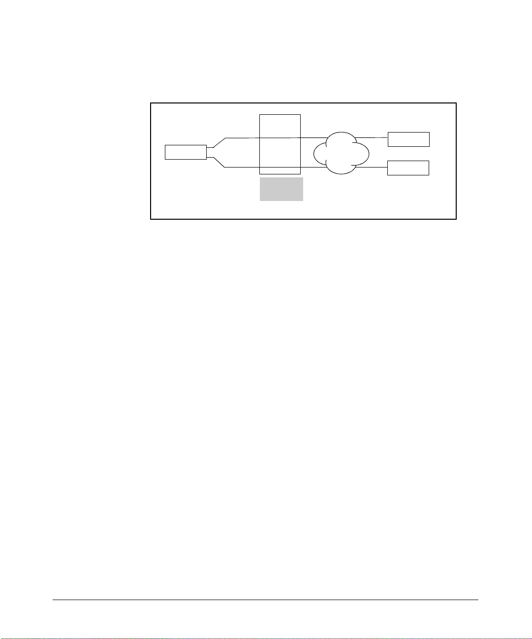
Increasing Bandwidth
Configuring MLFR
In essence, FRF.16 simply increases the committed information rate (CIR) you
can negotiate for a Frame Relay port in a T1 or E1 environment.
MLFR
E1
Router A
E1
bundle
Router B
Frame Relay
network
Router C
DLCI 101
DLCI 102
Figure 2-3. MLFR FRF.16
Figure 2-3 shows a Frame Relay connection that aggregates two E1-carrier
lines to connect to the Frame Relay provider. Router A establishes two PVCs—
one to Router B and one to Router C—on this connection.
You can aggregate as many carrier lines as are connected on the ProCurve
Secure Router, as long as they are of equal bandwidth. The MLFR interface
can carry as many PVCs as you request from your provider. Each PVC draws
on the aggregated bandwidth as needed, as available, and in accordance with
the CIR negotiated with the service provider. The endpoints of the PVC do not
have to use the same number of carrier lines (although a great difference in
bandwidth can lead to dropped packets). For example, Router A at the
company headquarters can use four E1 lines, while Router C at a small remote
site can connect to the network with only one line.
Enabling MLFR
Identify the Frame Relay interface for the connection whose bandwidth you
want to increase. Then, move the configuration mode context for this interface
and enable multilink. For example, you might enter:
ProCurve(config)# interface frame-relay 1
ProCurve(config-fr 1)# frame-relay multilink
2-9
Page 68

Increasing Bandwidth
Configuring MLFR
Binding Multiple Carrier Lines to a Frame Relay Interface
On the ProCurve Secure Router, links are always defined by the Data Link
Layer rather than the Physical Layer. You bind a physical interface to a logical
interface to grant the Data Link Layer protocol access to the physical media
over which to transmit data. This way of defining links makes configuring
MLFR easy: you simply bind more than one carrier line to the same Frame
Relay interface.
You can bind as many lines to the Frame Relay interface as are installed on
the router. The ProCurve Secure Router 7102dl provides up to 4 E1- or T1carrier lines. The ProCurve Secure Router 7203dl provides up to 12 E1- or T1carrier lines, depending on the modules that you purchase.
You should have already configured the physical interfaces. If you have not,
see the Basic Management and Configuration Guide, Chapter 4: Configur-
ing E1 and T1 Interfaces for instructions. To bind the physical interfaces to
the Frame Relay interface, you need this information:
■ type of carrier line (E1 or T1)
■ dl module slot for the carrier line’s module
■ port number for the interface to which the line connects
■ TDM group number
2-10
The TDM group number defines the range of channels used by an E1- or T1carrier line. Lines that will be aggregated can use the same or a different TDM
group number, but these lines must use the same number of channels.
If you bind a physical interface to the Frame Relay interface and then enable
multilink, the non-multilink binding is removed from the interface. You will
have to rebind the original line as well as the new lines to the Frame Relay
interface.
You can enter the bind command either from the global or the Frame Relay
interface configuration mode context. Enter the command for each carrier
line that you want to bundle:
Syntax: bind <bind number> [e1 | t1] <slot>/<port> <tdm group number> frame-relay
<interface number>
Each physical interface should be bound to the Frame Relay interface with a
unique bind number. For example, you might enter:
ProCurve(config)# bind 1 e1 1/1 1 fr 1
ProCurve(config)# bind 2 e1 1/2 1 fr 1
ProCurve(config)# bind 3 e1 2/1 1 fr 1
Page 69

Increasing Bandwidth
Configuring MLFR
Note You bind the physical interfaces to the Frame Relay interface, not the Frame
Relay subinterface. This is because Frame Relay subinterfaces define PVCs,
which are virtual connections, while the Frame Relay interface defines the
physical connection available to all the virtual ones.
Configuring the Bundle ID
MLFR manages the connection by periodically sending out hellos across each
carrier line included in the multilink connection. The hello includes the link
ID of the line and the bundle ID of the connection as a whole. The link ID lets
the router know which lines are up; the bundle ID lets the router know which
lines are actually part of the same logical connection.
By default, the Secure Router OS assigns this bundle ID to a Frame Relay
multilink:
MFR<interface number>
For example, the router might assign the bundle ID:
MFR1
You can configure a bundle ID for the connection. Move to the Frame Relay
interface configuration mode context and enter:
Syntax: frame-relay multilink bid <string>
The bundle ID can be up to 48 characters. It is a good idea to configure the
bundle ID at the same time as you enable multilink support: an active connection will go down briefly and then go back up while the new bundle ID is
negotiated.
2-11
Page 70

Increasing Bandwidth
Troubleshooting Multilinks
Troubleshooting Multilinks
Troubleshooting multilinks is similar to troubleshooting a link carried on a
single carrier line. You can review this process in “Standard Procedure” on
page 2-12. (For more troubleshooting tips, see the Basic Management and
Configuration Guide, Chapter 6: Configuring the Data Link Layer Protocol
for E1, T1, and Serial Interfaces.)
“Troubleshooting MLPPP” on page 2-15 and “Troubleshooting MLFR” on page
2-16 deal with special considerations for troubleshooting multilinks.
Note The show and debug commands that you use to troubleshoot are enable mode
commands. You can also enter them from any context except basic by adding
do to the beginning of the command.
Standard Procedure
When troubleshooting a multilink, follow the standard procedure for troubleshooting any PPP, Frame Relay, or Asymmetric Digital S ubscriber Line (ADSL)
connection:
2-12
1. Check the Physical Layer.
2. Check the Data Link Layer.
Physical Layer
Check the Stat LED for the module slot in which the line is installed. If the
LED is green, the Physical Layer is up. If you cannot send data over the link,
you will need to troubleshoot the Data Link Layer.
If the LED is red, try changing the cable and checking the other hardware. (If
the line is in a dual-module slot, you will need to use the show interfaces
command to determine which is port down.)
Next, check the configurations for the physical interface and make sure that
they match those used by your public carrier.
Data Link Layer
Different problems arise depending on the protocol the connection uses.
Page 71

Increasing Bandwidth
Troubleshooting Multilinks
PPP. Common PPP problems include:
■ mismatched DS0 or E0 channels
■ incorrect authentication information
■ incompatible network-level protocols
Use the debug commands shown in Table 2-1 to determine where the PPP
session establishment ends. A good strategy can be to first view only the errors
and then pinpoint the problem from there.
Caution Messages resulting from debug ppp commands consume processing power
and in a live network may compromise network functions.
Table 2-1. PPP Debug Commands
Command Syntax View
debug ppp verbose all PPP debug messages
debug ppp negotiation PPP messages dealing with negotiation of the link
debug ppp authentication PPP messages dealing with authentication
debug ppp errors errors and mismatches in negotiation and authentication
You can also view the status of an interface by entering show interface ppp
<interface number>.
If the LCP state does not open, the E1-carrier or T1-carrier lines have probably
been assigned an incorrect channel range. (This is properly a Physical Layer
problem but often does not show itself until peers exchange LCP frames.)
If you receive an authentication error and repeated Challenge Handshake
Authenticate Protocol (CHAP) or Password Authentication Protocol (PAP)
messages, you should check the router’s authentication information.
If you see NCP negotiation errors or if the LCP opens, but the PPP session
does not, determine which network protocol the peer uses. You may be using
incompatible protocols.
For more information about troubleshooting PPP and PPP authentication, see
the Basic Management and Configuration Guide, Chapter 6: Configuring
the Data Link Layer Protocol for E1, T1, and Serial Interfaces.
Frame Relay. Enter show frame-relay lmi to view the link management
interface (LMI) statistics.
2-13
Page 72
Increasing Bandwidth
Troubleshooting Multilinks
ProCurve# show frame-relay lmi
LMI statistics for interface FR 1 LMI TYPE = ANSI
Num Status Enq. Sent 24 Num Status Msgs Rcvd 7
Num Update Status Rcvd 1 Num Status Timeouts 3
Number of polls
sent
Number of polls
received
Figure 2-4. LMI Statistics for a Frame Relay Connection
On a functioning Frame Relay connection, the polls sent and received should
be approximately equal. The Frame Relay interface in Figure 2-4 has sent 17
polls without receiving a reply. Steadily increasing polls sent out without
replies probably indicate:
■ incompatible signaling type
■ incorrect signaling role
■ incorrect DLCI (also indicated by a deleted PVC)
■ mismatched DS0 or E0 channels
Table 2-2 gives the command syntax for displaying information about Frame
Relay connections.
Table 2-2. Frame Relay show Commands
Command Syntax View
show interfaces frame-relay <interface number> Frame Relay port:
• signaling type
• interface type (UNI or NNI)
2-14
show interfaces frame-relay <subinterface number> Frame Relay subinterface:
• PVC status
•DLCI
• IP address
show frame-relay pvc PVC end-to-end:
• PVC status
•DLCI
• packets in and out
• DE packets
• FECN/BECN packets
show frame-relay lmi LMI statistics—polls sent and
received
Page 73

Increasing Bandwidth
Troubleshooting Multilinks
View the Frame Relay interface and verify that its signaling type matches that
of your service provider. You can enter show interface fr <subinterface
number> to view a subinterface (the PVC endpoint) and check DLCIs and the
PVC state. If the Frame Relay interface is down, you probably have a problem
with the signaling type or role.
If the Frame Relay interface is up but a PVC is inactive or deleted, you probably
have a problem with the DLCI.
Also check the TDM channels configured for the physical interface. Even
though mismatched channels is a Physical Layer problem, it sometimes does
not manifest itself until peers attempt to establish a link.
For more information about troubleshooting Frame Relay, see the Basic
Management and Configuration Guide, Chapter 6: Configuring the Data
Link Layer Protocol for E1, T1, and Serial Interfaces.
Troubleshooting MLPPP
The most important consideration for troubleshooting MLPPP is determining
whether the peer supports it. To determine this, view PPP debug messages:
ProCurve# debug ppp negotiation
As you examine the output, look for the following two fields in the negotiation
events:
■ MRRU
■ ED
MRRU
An MRRU field automatically signals MLPPP support. In Figure 2-5, the router
receives a message with an MRRU option, which indicates that the peer
supports MLPPP.
If the peer at the other end of the link rejects this option, the ProCurve Secure
Router will terminate the link because it assumes its peer cannot support
MLPPP.
2-15
Page 74
Increasing Bandwidth
Troubleshooting Multilinks
2004.07.26 02:14:37 PPP.NEGOTIATION —-->>>>
:
PPPrx[t1 1/1] LCP: Conf-Req ID=133 Len=29 ACCM(00000000)
MAGIC(c0b82465) MRRU(1500) ED(3:0000000c045b)
PPPtx[t1 1/1] LCP: Conf-Ack ID=133 Len=29 ACCM(00000000)
MAGIC(c0b82465) MRRU(1500) ED(3:0000000c045b)
PPPrx[t1 2/1] LCP: Conf-Req ID=11 Len=29 ACCM(00000000)
MAGIC(c0b130b4) MRRU(1500) ED(3:0000000c045b)
PPPtx[t1 2/1] LCP: Conf-Ack ID=11 Len=29 ACCM(00000000)
MAGIC(c0b130b4) MRRU(1500) ED(3:0000000c045b)
2004.07.26 02:14:37 PPP.NEGOTIATION t1 1/1: LCP up
:
2004.05.26 02:14:37 PPP.NEGOTIATION PPPFSM: layer up, Protocol=c021
:
2004.07.26 02:14:37 PPP.NEGOTIATION t1 2/1: LCP up
2004.07.26 02:14:37 PPP.NEGOTIATION Links bundled
:
2004.07.26 02:21:15 PPP.NEGOTIATION PPPFSM: layer up, Protocol=8021
2004.07.26 02:21:15 PPP.NEGOTIATION IPCP up
2004.07.26 02:21:16 INTERFACE_STATUS.ppp 1 changed state to up
Multilink
support
T1 1/1 and T1
2/1 are the
same link
Figure 2-5. MLPPP Debug Messages
ED
Next, look for messages dealing with the ED option. The ED option identifies
the device transmitting the packet and allows the receiving peer to recognize
that frame fragments received on different carrier lines belong together. The
ED should be the same for each line in the bundle. For example, in Figure 2-5
the ED for the T1 1/1 interface and the T1 2/1 interface are the same.
Troubleshooting MLFR
To view debug messages for MLFR, enter the following command from the
enable mode context:
ProCurve# debug frame-relay multilink
MLFR periodically sends hellos to the remote endpoint. The local interface
should receive a hello ACK in reply. The Frame Relay interface should send a
hello for each carrier line. (See Figure 2-6.) If the interface is not sending hellos
for one of the carrier lines, then that line is down.
2-16
Page 75
Routers confirm a link is still
active.
Increasing Bandwidth
Troubleshooting Multilinks
ProCurve# debug frame-relay multilink
2005.07.12 12:12:39 FRAME_RELAY.MULTILINK (I): msg=HELLO, Link=t1 1/
2 1, Bundle=MFR1, BL state=UP
Message from service provider router
2005.07.12 12:12:39 FRAME_RELAY.MULTILINK (O): msg=HELLO_ACK, Link=t1
1/2 1, Bundle=MFR1, BL state=UP
Message from local router
2005.07.12 12:12:40 FRAME_RELAY.MULTILINK (O): msg=HELLO, Link=t1 1/
2 1, Bundle=MFR1, BL state=UP
2005.07.12 12:12:40 FRAME_RELAY.MULTILINK (I): msg=HELLO_ACK, Link=t1
1/2 1, Bundle=MFR1, BL state=UP
Figure 2-6. Frame Relay Multilink Hellos
If the interface is continually sending requests to add a link instead of hellos,
the endpoint probably does not support MLFR. It is also possible that carrier
lines on either end of the link are configured for a different set of channels.
(See Figure 2-7.)
ProCurve# debug frame-relay multilink
2005.07.12 12:11:54 FRAME_RELAY.MULTILINK (O): msg=ADD_LINK, Link=t1
1/1 1, Bundle=MFR1, BL state=ADD_SENT
2005.07.12 12:11:54 FRAME_RELAY.MULTILINK (O): msg=ADD_LINK, Link=t1
1/2 1, Bundle=MFR1, BL state=ADD_SENT
2005.07.12 12:11:54 FRAME_RELAY.MULTILINK (O): msg=ADD_LINK, Link=t1
1/1 1, Bundle=MFR1, BL state=ADD_SENT
2005.07.12 12:11:56 FRAME_RELAY.MULTILINK (O): msg=ADD_LINK, Link=t1
1/2 1, Bundle=MFR1, BL state=ADD_SENT
No messages from serv ice provider
State remains ADD_SENT
router
Figure 2-7. MLFR Link Does Not Go Up
Figure 2-8 shows a carrier line that was successfully added to a bundle.
2-17
Page 76
Increasing Bandwidth
Troubleshooting Multilinks
Routers exchange
requests to add a carrier
line to the bundle
ProCurve# debug frame-relay multilink
2005.07.12 12:11:54 FRAME_RELAY.MULTILINK (O): msg=ADD_LINK, Link=t1
1/2 1, Bundle=MFR1, BL state=ADD_SENT
Message from local router
2005.07.12 12:11:54 FRAME_RELAY.MULTILINK (I): msg=ADD_LINK, Link=t1
1/2 1, Bundle=MFR1, BL state=ADD_SENT
Message from se rvice provider router
2005.07.12 12:11:54 FRAME_RELAY.MULTILINK (I): msg=ADD_LINK_ACK,
Link=t1 1/2 1, Bundle=MFR1, BL state=ADD_SENT
2005.07.12 12:11:56 FRAME_RELAY.MULTILINK (I): msg=ADD_LINK, Link=t1
1/2 1, Bundle=MFR1, BL state=ADD_RX
2005.07.12 12:11:56 FRAME_RELAY.MULTILINK (O): msg=ADD_LINK_ACK,
Link=t1 1/2 1, Bundle=MFR1, BL state=ADD_RX
Link ID
Bundle ID
at least one peer has
confirmed the carrier line
Figure 2-8. Successfully Adding a MLFR Link
2-18
Page 77

Increasing Bandwidth
Quick Start
Quick Start
This section provides the commands you must enter to quickly configure:
■ Multilink PPP (MLPPP)
■ Multilink Frame Relay (MLFR)
Only a minimal explanation is provided. If you need additional information
about any of these options, check “Contents” on page 2-1 to locate the section
that contains the explanation you need.
You may want to print out and complete Table 2-3 to use while you configure
your router.
Table 2-3. Quick Start Configuration Worksheet
Line Parameter Your Setting
new physical line 1 slot
port
new physical line 2 slot
port
new physical line 3 slot
port
existing line TDM group number
channels
logical interface type
logical interface number
IP address (logical interface)
2-19
Page 78

Increasing Bandwidth
Quick Start
MLPPP Configuration
Before you begin completing these instruction, you should connect the physical interfaces to the appropriate public carrier equipment. You should also
have a non-multilink PPP connection up and running.
1. Move to the global configuration mode context and configure the physical
interface(s) for the new carrier line(s):
a. Move to the interface configuration mode context:
Syntax: interface
b. TDM group numbers are significant for the interface only, so you can
use the same TDM group number as the original line. You must use
the same number of channels:
Syntax: tdm-group
For example, you might enter:
ProCurve(config-e1 1/2)# tdm-group 1 timeslots 1-31
c. Activate the interface:
ProCurve(config-e1 1/2)# no shutdown
d. Repeat these steps for each new carrier line.
2. Move to the PPP interface for the connection:
Syntax: interface ppp <interface number>
3. Enable multilink functions:
ProCurve(config-ppp 1)# ppp multilink
4. Bind each new physical interface to the PPP interface:
Syntax: bind <bind number> [e1 | t1] <slot>/<port> <tdm group number> ppp
<interface number>
Use a different bind number for each physical interface. For example, you
might enter:
[e1 | t1] <slot>/<port>
<tdm group number> timeslots <channels>
2-20
ProCurve(config-ppp 1)# bind 2 e1 1/2 1 ppp 1
ProCurve(config-ppp 1)# bind 3 e1 2/1 1 ppp 1
Page 79

Increasing Bandwidth
If you do not already have a PPP connection running, you must also:
5. Assign the PPP interface an IP address:
Syntax: ip address [<A.B.C.D> <subnet mask | /prefix length> | negotiated]
For example, you might enter:
ProCurve(config-ppp 1)# ip address 10.1.1.1 /30
You can also have the interface take its address from the far end of the
link (negotiated). A PPP interface can take a dynamic address from a
DHCP server only when it is acting as a bridge. The interface can also take
its address from another router interface, such as the Ethernet interface:
Syntax: ip unnumbered <interface ID>
6. Activate the PPP interface:
ProCurve(config-ppp 1)# no shutdown
Quick Start
MLFR Configuration
Before you begin completing these instruction, you should connect the physical interfaces to the appropriate public carrier equipment. You should also
have a non-multilink Frame Relay connection up and running.
1. Move to the global configuration mode context and configure the physical
interface(s) for the new carrier line(s):
a. Move to the interface configuration mode context:
Syntax: interface [e1 | t1] <slot>/<port>
b. Configure the TDM group. You can use the same TDM group as the
original line. You must use the same number of channels:
Syntax: tdm-group
c. Activate the interface:
Syntax: no shutdown
d. Repeat these steps for each new carrier line.
2. Move to the Frame Relay interface for the connection:
Syntax: interface frame-relay <interface number>
3. Enable multilink functions:
ProCurve(config-fr 1)# frame-relay multilink
<tdm group number> timeslots <channels>
2-21
Page 80

Increasing Bandwidth
Quick Start
4. Enabling multilink unbinds physical lines from the interface. As well as
binding each new physical interface to the Frame Relay interface, you
must rebind the original line:
Syntax: bind <bind number> [e1 | t1] <slot>/<port> <tdm group number> frame-
relay <interface number>
Use a different bind number for each physical interface. For example, you
might enter:
ProCurve(config-fr 1)# bind 1 t1 1/1 1 fr 1
ProCurve(config-fr 1)# bind 2 t1 2/1 1 fr 1
5. Assign the Frame Relay interface a bundle ID:
Syntax: frame-relay multilink bid <string>
If you do not already have a Frame Relay connection running, you must
also:
6. Activate the Frame Relay interface:
ProCurve(config-fr 1)# no shutdown
7. Add at least one PVC by configuring a Frame Relay subinterface:
ProCurve(config-fr 1)# interface frame-relay 1.101
2-22
8. Enter the DLCI for the PVC:
Syntax: frame-relay interface-dlci <DLCI>
9. Assign the Frame Relay subinterface an IP address:
Syntax: ip address [dhcp | <A.B.C.D> <subnet mask | /prefix length>]
For example, you might enter:
ProCurve(config-fr 1.101)# ip address 10.2.2.1 /30
The Frame Relay subinterface can also act as a DHCP client and take a
dynamic address from a connecting server. Use the dhcp option. The
interface can also take an address from another router interface, such as
an Ethernet interface:
Syntax: ip unnumbered <interface ID>
You might also need to change the signaling type and role for the Frame Relay
interface. For more information about configuring Frame Relay, see the Basic
Management and Configuration Guide, Chapter 6: Configuring the Data
Link Layer Protocol for E1, T1, and Serial Interfaces.
Page 81

Configuring Backup WAN Connections
Contents
Backing Up Primary WAN Connections . . . . . . . . . . . . . . . . . . . . . . . . . . . . 3-5
Analog Backup Connections . . . . . . . . . . . . . . . . . . . . . . . . . . . . . . . . . . 3-5
ISDN-Backup Connections . . . . . . . . . . . . . . . . . . . . . . . . . . . . . . . . . . . 3-6
BRI ISDN . . . . . . . . . . . . . . . . . . . . . . . . . . . . . . . . . . . . . . . . . . . . . . . 3-7
Electrical Specifications for BRI ISDN . . . . . . . . . . . . . . . . . . . . . . 3-9
Backup Modules for the ProCurve Secure Router . . . . . . . . . . . . . . . . 3-9
Standards . . . . . . . . . . . . . . . . . . . . . . . . . . . . . . . . . . . . . . . . . . . . . 3-10
Data Link Layer Protocols . . . . . . . . . . . . . . . . . . . . . . . . . . . . . . . 3-11
Determining a Backup Method . . . . . . . . . . . . . . . . . . . . . . . . . . . . . . . . . . . 3-11
Using Demand Routing for Backup Connections . . . . . . . . . . . . . . . . 3-12
Using Persistent Backup Connections . . . . . . . . . . . . . . . . . . . . . . . . . 3-14
Comparing Demand Routing and Persistent Backup
Connections . . . . . . . . . . . . . . . . . . . . . . . . . . . . . . . . . . . . . . . . . . . . . . . 3-14
3
Configuring Demand Routing for Backup Connections . . . . . . . . . . . . . . 3-17
Define the Traffic That Triggers the Connection . . . . . . . . . . . . . . . . 3-18
Specifying a Protocol . . . . . . . . . . . . . . . . . . . . . . . . . . . . . . . . . . . . 3-18
Defining the Source and Destination Addresses . . . . . . . . . . . . . 3-19
Configuring the Demand Interface . . . . . . . . . . . . . . . . . . . . . . . . . . . . 3-20
Creating the Demand Interface . . . . . . . . . . . . . . . . . . . . . . . . . . . 3-21
Configuring an IP Address . . . . . . . . . . . . . . . . . . . . . . . . . . . . . . . 3-22
Matching the Interesting Traffic . . . . . . . . . . . . . . . . . . . . . . . . . . . 3-23
Specifying the connect-mode Option . . . . . . . . . . . . . . . . . . . . . . 3-26
Associating a Resource Pool with the Demand
Interface . . . . . . . . . . . . . . . . . . . . . . . . . . . . . . . . . . . . . . . . . . . . . . 3-27
Defining a Connect Sequence . . . . . . . . . . . . . . . . . . . . . . . . . . . . . 3-27
Specify the Order in Which Connect Sequences Are Used . . . . . 3-29
Configure the Number of Connect Sequence Attempts . . . . . . . 3-30
3-1
Page 82

Configuring Backup WAN Connections
Contents
Configuring the BRI or Modem Interface . . . . . . . . . . . . . . . . . . . . . . . 3-37
Configuring a Floating Static Route for the Demand Interface . . . . . 3-42
Configuring PPP Authentication for an ISDN Connection . . . . . . . . 3-43
Example of Demand Routing with PAP Authentication for a
Backup Connection . . . . . . . . . . . . . . . . . . . . . . . . . . . . . . . . . . . . . . . . . 3-45
Setting the MTU for Demand Interfaces . . . . . . . . . . . . . . . . . . . . . . . 3-46
Configure the connect-sequence interface-recovery
Option . . . . . . . . . . . . . . . . . . . . . . . . . . . . . . . . . . . . . . . . . . . . . . . . 3-30
Understanding How the connect-sequence
Commands Work . . . . . . . . . . . . . . . . . . . . . . . . . . . . . . . . . . . . . . . 3-32
Configuring the idle-timeout Option . . . . . . . . . . . . . . . . . . . . . . . 3-34
Configuring the fast-idle Option . . . . . . . . . . . . . . . . . . . . . . . . . . . 3-35
Defining the caller-number . . . . . . . . . . . . . . . . . . . . . . . . . . . . . . . 3-36
Defining the called-number . . . . . . . . . . . . . . . . . . . . . . . . . . . . . . 3-36
Configuring the Hold Queue . . . . . . . . . . . . . . . . . . . . . . . . . . . . . . 3-36
Accessing the BRI or Modem Interface . . . . . . . . . . . . . . . . . . . . . 3-38
Configuring the ISDN Signaling (Switch) Type . . . . . . . . . . . . . . 3-38
Configuring an LDN for ISDN BRI S/T Modules . . . . . . . . . . . . . 3-39
Configuring a SPID and LDN for ISDN BRI U Modules . . . . . . . 3-40
Setting the Country for the Modem Interface . . . . . . . . . . . . . . . 3-40
Assigning BRI or Modem Interface to the Resource Pool . . . . . 3-41
Activating the Interface . . . . . . . . . . . . . . . . . . . . . . . . . . . . . . . . . . 3-41
Caller ID Options for ISDN BRI Backup Modules
(Optional) . . . . . . . . . . . . . . . . . . . . . . . . . . . . . . . . . . . . . . . . . . . . . 3-42
Enabling PPP Authentication for All Demand Interfaces . . . . . . 3-43
Configuring PAP Authentication for a Demand Interface . . . . . 3-44
Configuring CHAP Authentication for a Demand Interface . . . . 3-44
Configuring the Username and Password That the Router
Expects to Receive . . . . . . . . . . . . . . . . . . . . . . . . . . . . . . . . . . . . . 3-44
Configuring Peer IP Address . . . . . . . . . . . . . . . . . . . . . . . . . . . . . 3-46
3-2
Configuring a Persistent Backup Connection . . . . . . . . . . . . . . . . . . . . . . . 3-47
Configuring the Physical Interface for a Persistent Backup
Connection . . . . . . . . . . . . . . . . . . . . . . . . . . . . . . . . . . . . . . . . . . . . . . . . 3-47
Configuring a BRI Interface (ISDN Only) . . . . . . . . . . . . . . . . . . . 3-47
Configuring a Modem Interface (Analog Only) . . . . . . . . . . . . . . 3-51
Using the Modem for Console Dial-In . . . . . . . . . . . . . . . . . . . . . . 3-53
Replacing Incoming Caller ID for BRI and Modem Interfaces . . . . . 3-53
Page 83

Configuring Backup WAN Connections
Contents
Configuring a Logical Interface for a Persistent Backup
Connection . . . . . . . . . . . . . . . . . . . . . . . . . . . . . . . . . . . . . . . . . . . . . . . . 3-54
Creating a Backup PPP Interface . . . . . . . . . . . . . . . . . . . . . . . . . . 3-55
Activating the Interface . . . . . . . . . . . . . . . . . . . . . . . . . . . . . . . . . . 3-55
Setting an IP Address . . . . . . . . . . . . . . . . . . . . . . . . . . . . . . . . . . . . 3-56
Enabling PPP Authentication . . . . . . . . . . . . . . . . . . . . . . . . . . . . . 3-56
Configuring Persistent Backup Settings for a Primary
Connection . . . . . . . . . . . . . . . . . . . . . . . . . . . . . . . . . . . . . . . . . . . . . . . . 3-58
Accessing the Primary Connection’s Logical Interface . . . . . . . . 3-58
Setting the Backup Call Mode . . . . . . . . . . . . . . . . . . . . . . . . . . . . 3-59
Adding a Number to a Backup Dial List . . . . . . . . . . . . . . . . . . . . 3-63
Controlling When a Backup Connection Can
Be Established . . . . . . . . . . . . . . . . . . . . . . . . . . . . . . . . . . . . . . . . . 3-64
Setting Backup Timers . . . . . . . . . . . . . . . . . . . . . . . . . . . . . . . . . . 3-66
Configuring a Floating Static Route for a Persistent Backup
Connection . . . . . . . . . . . . . . . . . . . . . . . . . . . . . . . . . . . . . . . . . . . . . . . . 3-67
Configuring Persistent Backup for Multiple Connections . . . . . . . . . 3-69
Viewing Backup Configurations and Troubleshooting Backup
Connections . . . . . . . . . . . . . . . . . . . . . . . . . . . . . . . . . . . . . . . . . . . . . . . . . . 3-70
Viewing Information about BRI and Modem Interfaces and
Troubleshooting Problems . . . . . . . . . . . . . . . . . . . . . . . . . . . . . . . . . . . 3-70
Viewing the Status and Configuration of Backup
Interfaces . . . . . . . . . . . . . . . . . . . . . . . . . . . . . . . . . . . . . . . . . . . . . 3-71
Viewing Information about Demand Routing and
Troubleshooting Problems . . . . . . . . . . . . . . . . . . . . . . . . . . . . . . . . . . . 3-75
Viewing the Status of the Demand Interface . . . . . . . . . . . . . . . . 3-75
Viewing a Summary of Information about the Demand
Interface . . . . . . . . . . . . . . . . . . . . . . . . . . . . . . . . . . . . . . . . . . . . . . 3-77
Viewing Demand Sessions . . . . . . . . . . . . . . . . . . . . . . . . . . . . . . . 3-78
Viewing the Resource Pool . . . . . . . . . . . . . . . . . . . . . . . . . . . . . . . 3-78
Show the Running-Config for the Demand Interface . . . . . . . . . 3-79
Troubleshooting Demand Routing . . . . . . . . . . . . . . . . . . . . . . . . 3-79
Checking the Demand Interface . . . . . . . . . . . . . . . . . . . . . . . . . . . 3-79
Checking the ACL That Defines the Interesting Traffic . . . . . . . 3-80
Troubleshooting the Backup Connection . . . . . . . . . . . . . . . . . . . 3-81
Test Calls for ISDN Lines . . . . . . . . . . . . . . . . . . . . . . . . . . . . . . . . 3-83
Troubleshooting PPP for a Demand Routing Backup
Connection . . . . . . . . . . . . . . . . . . . . . . . . . . . . . . . . . . . . . . . . . . . . 3-84
3-3
Page 84

Configuring Backup WAN Connections
Contents
Viewing Information about Persistent Backup Connections
and Troubleshooting Problems . . . . . . . . . . . . . . . . . . . . . . . . . . . . . . . 3-84
Monitoring the Dial-Up Process . . . . . . . . . . . . . . . . . . . . . . . . . . . . . . 3-87
Troubleshooting Persistent Backup Connections . . . . . . . . . . . . . . . 3-89
Quick Start . . . . . . . . . . . . . . . . . . . . . . . . . . . . . . . . . . . . . . . . . . . . . . . . . . . . 3-94
Configuring Demand Routing for Backup Connections . . . . . . . . . . . 3-94
Configuring a Persistent Backup Connection . . . . . . . . . . . . . . . . . . 3-101
Backing up a Connection with an ISDN BRI S/T
Backup Module . . . . . . . . . . . . . . . . . . . . . . . . . . . . . . . . . . . . . . . . . . . 3-105
Backing up a Connection with an Analog Module . . . . . . . . . . . . . . 3-107
Viewing Backup Settings . . . . . . . . . . . . . . . . . . . . . . . . . . . . . . . . . 3-85
Viewing the Backup PPP Interface . . . . . . . . . . . . . . . . . . . . . . . . 3-87
Standard Procedures . . . . . . . . . . . . . . . . . . . . . . . . . . . . . . . . . . . . 3-89
3-4
Page 85

Configuring Backup WAN Connections
Backing Up Primary WAN Connections
Backing Up Primary WAN Connections
To ensure that users can always exchange data between two offices, you may
want to lease a dial-up WAN connection—such as an Integrated Services
Digital Network (ISDN) or telephone line—which can be used as a redundant
line in case a primary WAN connection fails. Dial-up WAN connections work
well as backup connections because you pay only for the time when the
connection is in use.
Like other WAN connections, dial-up connections are provided through the
public carrier network. In North America, dial-up connections are provided
through the public switched telephone network (PSTN). Outside of North
America, each country’s public telephone and telegraph (PTT) authority
provides dial-up connections.
All WAN connections, including dial-up connections, consist of three basic
elements:
■ the physical transmission media
■ electrical signaling specifications for generating, transmitting, and receiv-
ing the signals that transmit data through the telephone cables
■ Data Link Layer protocols, which provide logical flow control for moving
data between the router and the public carrier’s central office (CO)
Just as you configure both a Physical Layer and a Data Link Layer for primary
WAN connections, you must configure these layers for backup connections.
Configuring the Physical and Data Link Layers for backup connections is a
slightly different process, however, because you must specify when and how
the backup connection is initiated.
Analog Backup Connections
If you want to create a backup connection over the existing telephone cabling,
you can use an analog modem, which establishes a dial-up connection to its
peer—another analog modem at the remote office. To initiate a physical
connection, the analog modem places a telephone call to its peer and then
negotiates a logical link with the peer using a Data Link Layer protocol. After
the connection is established, the analog modem translates digital data into
analog signals. When the two peers are finished exchanging data, the analog
modem terminates the connection just as a person would hang up a call.
3-5
Page 86

Configuring Backup WAN Connections
Backing Up Primary WAN Connections
Analog modems provide comparatively little bandwidth. (The ProCurve
Secure Router analog module provides between 300 bps and 33.6 kbps.) When
analog modems are incorporated into WAN routers, they are designed only to
provide redundancy for other WAN lines, not to furnish a long-term WAN
connection.
ISDN-Backup Connections
ISDN is a dial-up WAN connection that supports voice, data, fax, and video
services over standard telephone lines. Unlike analog communications, ISDN
communications are digital.
Public carriers offer two types of ISDN services:
■ Basic Rate Interface (BRI)
■ Primary Rate Interface (PRI)
ISDN BRI provides two 64-Kbps bearer (B) channels and one 16 Kbps data (D)
channel. The B channels carry data, and the D channel handles the signaling
and call control for the ISDN line.
PRI ISDN, on the other hand, provides 23 B channels and 1 D channel in North
America and Japan. It provides 30 B channels and 1 D channel in Europe, Asia
(except Japan), Australia, and South America. (When PRI includes 30 B
channels, channel 0 is used to maintain synchronization and is not counted as
either a B or D channel.) The transmission rates for PRI ISDN match the
transmission rates for an E1- or T1-carrier line. In North America and Japan,
PRI ISDN provides 1.544 Mbps. In other areas, PRI ISDN provides 2.048 Mbps.
3-6
In an ISDN connection, the B channels are treated independently. They can
be used for simultaneous voice and data; in other words, you can talk on the
phone and surf the Web at the same time. For example, if you have an ISDN
BRI connection, you can use both channels for data transmissions to a remote
network, or you can use each channel to connect to a different remote office.
Because the ProCurve Secure Router supports BRI ISDN for backup connections, this chapter focuses on BRI ISDN. (The ProCurve Secure Router also
supports BRI ISDN for primary WAN connections. For more information, see
Chapter 8: Configuring Demand Routing for Primary ISDN Modules in the
Basic Management and Configuration Guide.)
Page 87
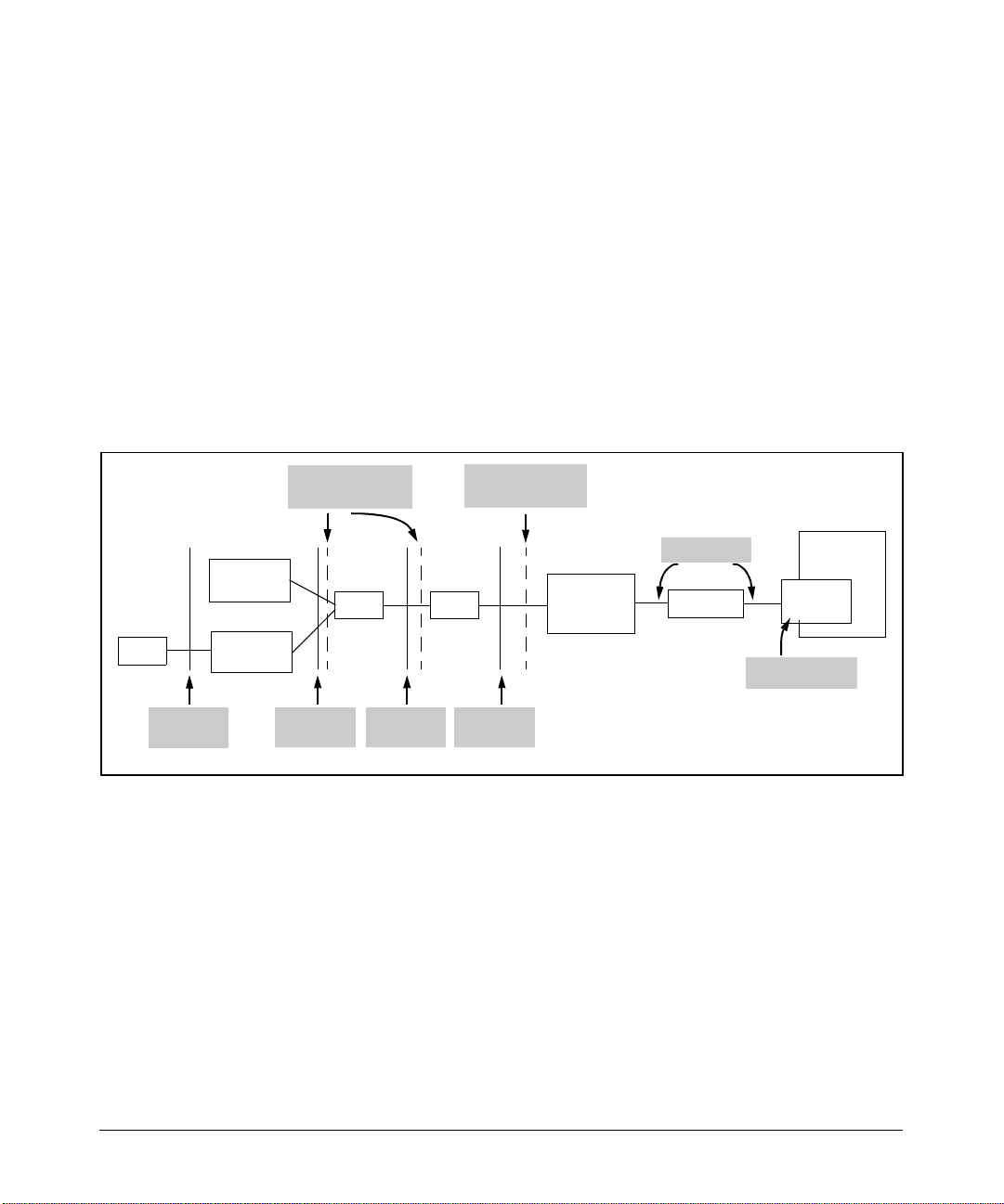
Configuring Backup WAN Connections
Backing Up Primary WAN Connections
BRI ISDN
BRI ISDN operates over the twisted-pair cabling that is used for ordinary
telephones. All of the telecommunications infrastructure that is used to
connect your LAN to the CO is collectively called the local loop.
The local loop is divided into two sections by a line of demarcation (demarc),
which separates your company’s wiring and equipment from the public carrier’s wiring and equipment. (See Figure 3-1.) As a general rule, your company
owns, operates, and maintains the wiring and equipment on its side of the
demarc, and the public carrier owns, operates, and maintains the wiring and
equipment on its side of the demarc. For ISDN connections, the position of
the demarc varies, depending on which ISDN equipment the public carrier
provides.
TE2
R
interface
TEI
(Router)
Terminal
adapter
Demarc (outside
North America)
NT2
S
interfaceT interfaceUinterface
NT1
Demarc
(North America)
Interface Unit
(Smart Jack)
Network
Wire span
Repeater
Public
Carrier’s CO
ISDN
Switch
ISDN Switch
Figure 3-1. ISDN Network
In addition to the demarc, the local loop includes:
■ ISDN switch—At the public carrier’s CO, the ISDN switch multiplexes and
de-multiplexes channels on the twisted pair wiring of the local loop. It
provides the physical and electrical termination for the ISDN line and then
forwards the data onto the public carrier’s network.
■ Repeater—A repeater receives, amplifies, and retransmits the digital
signal so that the signal is always strong enough to be read. Because ISDN
lines use 2B1Q coding, which operates at a lower frequency range than
T1 or E1 encoding, repeaters are required only every 5.49 km (18,000 feet).
In contrast, T1 encoding requires a repeater approximately every 1.6 km
(1 mile or 5,280 feet).
3-7
Page 88

Configuring Backup WAN Connections
Backing Up Primary WAN Connections
■
Wire span—Because public carrier networks were originally designed to
carry analog voice calls, copper wire is the most common physical transmission medium used on the local loop. Although copper wire has a limited
signal-carrying capacity, ISDN is designed to maximize its capability.
■ Network Interface Unit (NIU)—The NIU automatically maintains the
WAN connection and enables public carrier employees to perform simple
management tasks from a remote location. The NIU is usually located
outside the subscriber’s premises so that public carrier employees can
always access it. (The NIU is commonly referred to as the “smart jack” in
North America.)
■ Network Termination (NT) 1—The NT1 provides the physical and electri-
cal termination for the ISDN line. It monitors the line, maintains timing,
and provides power to the ISDN line. In Europe and Asia, public carriers
supply the NT1. In North America, however, the subscriber provides the
NT1. In fact, many ISDN vendors are now building the NT1 directly into
ISDN equipment such as routers.
■ NT 2—PRI ISDN also requires an NT2, which provides switching functions
and data concentration for managing traffic across multiple B channels.
In many regions, the NT1 and NT2 are combined into a single device,
which is called an NT12 (NT-one-two) or just NT.
■ Terminal equipment (TE) 1—TE1 devices are ISDN-ready devices and can
be connected directly to the NT1 or the NT2. TE1 devices include routers,
digital phones, and digital fax machines.
■ TE2—TE2 devices do not support ISDN and cannot connect directly to
an ISDN network. TE2 devices require a terminal adapter (TA) to convert
the analog signals produced by the TE2 device into digital signals that can
be transmitted over an ISDN connection. TE2 devices include analog
telephones and analog fax machines.
■ Terminal adapter (TA)—A TA allows you to connect a TE2 device to an
ISDN network.
3-8
You do not need to understand all of the equipment used to create the local
loop with great technical precision. However, if your ISDN line ever goes
down, a basic knowledge and working vocabulary can help you troubleshoot
problems with your public carrier.
You should also understand that the demarc defines which equipment your
organization is responsible for maintaining. In addition, the demarc determines the type of ISDN backup module you use, as explained in the next
section.
Page 89

Configuring Backup WAN Connections
Backing Up Primary WAN Connections
ISDN Interfaces. The ISDN standard defines four interfaces, or points, at
which equipment can be added to the ISDN network:
■ U interface (between the NT1 and the NIU)
■ T interface (between the NT2 and the NT1)
■ S interface (between the TE1 and the NT2)
■ R interface (between the TE2 and the TA)
In Europe, Asia, and all other locations outside of North America, PTTs supply
the NT devices. The demarc then falls between the TE (in your case, the
router) and the NT1 at the S/T interface. The ProCurve Secure Router provides
an ISDN BRI S/T module, which enables a backup interface to connect to
either the NT2 or the NT1 provided by your PTT.
In North America, the subscriber must provide the NT devices. The demarc
falls between the NT devices and the public carrier’s NIU (or smart jack) at
the U interface. The ProCurve Secure Router’s ISDN BRI U module contains
the NT1 and enables a backup interface to function as a U interface.
Electrical Specifications for BRI ISDN
ISDN lines use 2B1Q coding, which uses four signal levels rather than the two
of T1- or E1-carrier lines. Each of the four levels, represented by a quaternary,
corresponds to a combination of two bits. For example, the signal level for 1
followed by 1 is different for that of 1 followed by 0. This coding scheme allows
BRI ISDN lines to compress data. Also, 2B1Q operates at a lower frequency
range than T1/E1 encoding and sustains fewer losses with fewer repeaters.
Backup Modules for the ProCurve Secure Router
All narrow Data Link m odules on the ProCurve Secure Router provide an extra
port for a backup interface. To activate the backup interface, you must
purchase and install one of the following backup modules:
■ analog
■ ISDN BRI U
■ ISDN BRI S/T
The ProCurve Secure Router supports BRI ISDN, which provides a transmission rate of 64 Kbps or 128 Kbps. The analog module on the ProCurve Secure
Router supports between 300 bps and 33.6 Kbps.
3-9
Page 90
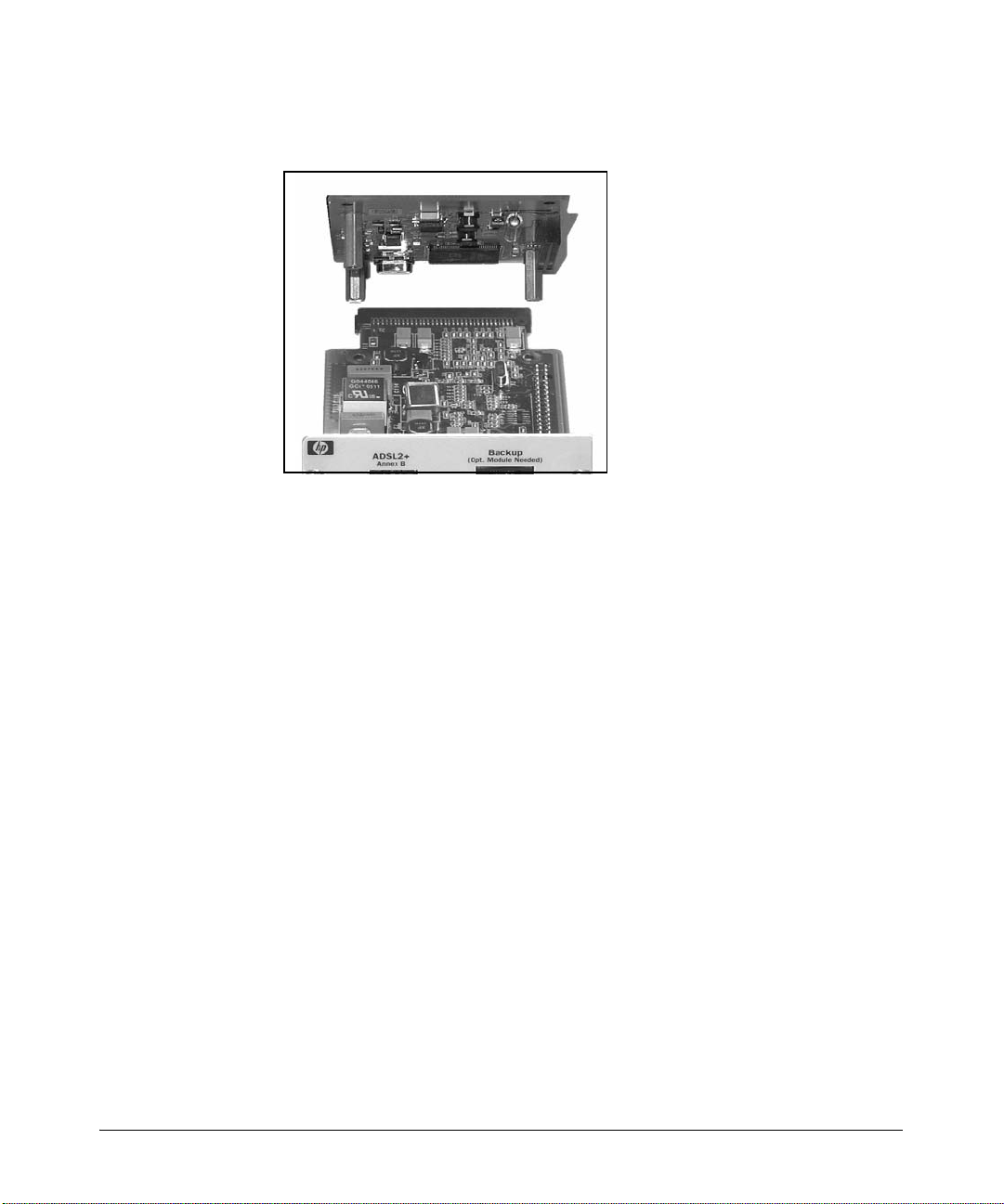
Configuring Backup WAN Connections
Backing Up Primary WAN Connections
As Figure 3-2 shows, the backup module is installed over the data link module.
Figure 3-2. Installing a Backup Module
After the backup module is installed, it can back up any interface on the router,
not only those interfaces installed in the same slot. You can back up:
■ Point-to-Point Protocol (PPP) connections
■ High-level Data Link Control (HDLC) connections
■ Frame Relay connections
■ ISDN primary connections
■ Asymmetric Digital Subscriber Line (ADSL) connections
■ Internet connections (using any Data Link Layer protocol)
3-10
Standards
On the ProCurve Secure Router, both ISDN backup modules support the
following standards:
■ National ISDN-1—Defined in the mid 1990s by the National Institute of
Standards and Technology (NIS) and Bellcore (now called Telcordia),
National ISDN-1 specifies a common set of options that ISDN manufacturers and public carriers must provide.
■ Northern Telecom Digital Multiplex System (DMS)-100—DMS-100 is
another standard for transmitting voice and data over an ISDN line.
■ AT&T 5ESS—AT&T switches use Lucent signaling.
Page 91

Configuring Backup WAN Connections
Determining a Backup Method
In addition to these three options, the ISDN BRI S/T backup supports:
■ Euro-ISDN—Also called Normes Européennes de Télécommunication 3
(NET3), Euro-ISDN was defined in the late 1980s by the European Commission so that equipment manufactured in one country could be used
throughout Europe.
You must configure your router’s BRI interface for the type of signaling your
service provider implements. Because switches can implement various types
of signaling depending on their software, the signaling type will not always be
that of the CO switch’s manufacturer.
Data Link Layer Protocols
On the ProCurve Secure Router, backup ISDN connections always use PPP as
the Data Link Layer protocol, no matter what Data Link Layer protocol is used
for the primary connection. For example, if the ISDN line is used to back up
a Frame Relay connection between two offices, the ISDN uses PPP.
Determining a Backup Method
The ProCurve Secure Router initiates a backup connection in response to a
backup condition. Backup conditions include Layer 1, or Physical Layer,
failures such as:
■ T1 and E1 alarms
■ ADSL failure due to low signal-to noise ratio (SNR)
■ other line failures and WAN alarms
Backup conditions also include Layer 2, or Data Link Layer, failures such as:
■ signaling failure
■ loss of permanent virtual circuit (PVC)
You have two choices for configuring how the ProCurve Secure Router
responds to a backup condition:
■ You can configure demand routing, which is activated only if both of the
following conditions are met:
• A backup condition occurs, bringing the primary interface down.
• The router receives traffic that must be transmitted to the far-end
network.
3-11
Page 92

Configuring Backup WAN Connections
Determining a Backup Method
■ You can configure a persistent backup connection, which is initiated
immediately if a backup condition occurs on the primary connection and
stays up until the primary connection is available again.
Before you configure a backup connection, you should evaluate your network
environment and then determine which option best meets your company’s
particular needs.
Using Demand Routing for Backup Connections
Demand routing allows you to capitalize on the main advantage of a dial-up
connection: it establishes the dial-up connection when it is needed and
terminates the connection when it is no longer necessary. For example, you
may lease an ISDN line to serve as the backup WAN connection between the
main office and a branch office. If the primary interface goes down and no one
is transmitting traffic, you may not want the backup WAN connection to
become active. This type of usage would substantially increase your company’s telephone costs. Instead, you may want to establish the ISDN connection only when two conditions are met:
■ the primary interface goes down
■ traffic must be transmitted between the two offices
Demand routing only establishes the backup connection when traffic is sent
from the main office to the branch office and the primary interface is unavailable. (See Figure 3-3.)
In addition to establishing the connection only when it is needed for data
transmission, demand routing ensures that when the dial-up connection is idle
for certain amount of time, the ProCurve Secure Router terminates the call.
You can configure the idle timer to match the rates you are charged for the
ISDN line. For example, if your service provider charges your company for
every two minutes that the ISDN line is established, you can set the idle timer
to 110 seconds. The ProCurve Secure Router will then disconnect the ISDN
line when it has been idle for 110 seconds, and your company will not be
charged for an additional two minutes.
With demand routing, you can also be very selective in the type of traffic that
causes the router to initiate the ISDN connection. For example, you can limit
this “interesting” traffic to packets sent from one subnet to another subnet.
You can also exclude routing updates (if you are using a routing protocol) and
other traffic that you do not think is essential. Carefully selecting the type of
traffic that triggers an ISDN connection limits the amount of time that your
company uses its ISDN connection, thereby decreasing costs.
3-12
Page 93
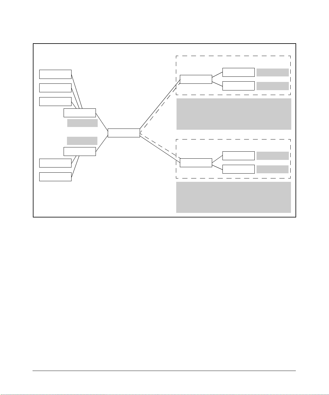
Configuring Backup WAN Connections
Determining a Backup Method
Branch Office B
Edge Switch
Edge Switch
Edge Switch
Edge Switch
Edge Switch
Core Switch
192.168.1.0
192.168.2.0
Core Switch
Main Router
Frame Relay
over E1
Backup ISDN
connections
Frame Relay
over E1
Switch
Branch Router
Switch
The backup ISDN connection to Branch Office B is
triggered only when the primary interface on the Main
Router goes down and traffic with destination address
192.168.3.0 /24 or 192.168.4.0 /24 is forwarded to demand
interface 1 on the Main Router.
Branch Office C
Switch
Branch Router
Switch
The backup ISDN connection to Branch Office C is
triggered only when the primary interface on the Main
Router goes down and traffic with destination address
192.168.5.0 /24 or 192.168.6.0 /24 is forwarded to dem and
interface 2 on the Main Router.
192.168.3.0
192.168.4.0
192.168.5.0
192.168.6.0
Figure 3-3. Using Demand Routing for Backup Connections
Demand routing has another advantage: it supports two-port ISDN modules.
If you are not using all of the narrow slots in your ProCurve Secure Router,
you can purchase a two-port ISDN module and use it as a primary WAN
connection or as a backup to other primary WAN connections. To use the twoport module for backup connections, you follow the instructions outlined in
Chapter 8: Configuring Demand Routing for Primary ISDN Modules in the
Basic Management and Configuration Guide, with one exception. Rather
than creating a static route to the far-end network, you create a floating static
route, ensuring that the administrative distance for this floating static route is
higher than the administrative distance for the route through the primary
interface. For more information about static routes, see “Configuring a Floating Static Route for a Persistent Backup Connection” on page 3-67.
If you purchase this two-port ISDN module, you can use Multilink PPP
(MLPPP) to aggregate channels across ISDN lines, increasing bandwidth for
the dial-up connection.
3-13
Page 94

Configuring Backup WAN Connections
Determining a Backup Method
If you use the backup ISDN modules, you cannot use MLPPP to aggregate
channels. The ISDN backup modules support bonding, rather than channel
aggregation. You can bond channels on an ISDN backup module only if:
■ you configure a persistent backup connection
■ the router connects to another ProCurve Secure Router
If both of these conditions are met, you can use bonding to increase bandwidth.
Note If you use demand routing with a backup ISDN module, you can neither bond
nor multilink channels.
Using Persistent Backup Connections
You can also configure the backup module so that it immediately establishes
a dial-up connection when the primary interface fails. This connection stays
up until the primary interface is available again. You may want to configure
this type of backup connection between offices that require a constant connection.
The ProCurve Secure Router provides some settings to control when a persistent backup connection is established. For example, you can prevent the
connection from becoming active on weekends or evenings.
3-14
As mentioned earlier, when you configure a persistent backup connection,
you can bond two B channels for a total of 128 Kbps. The only limitation is
that the router must connect to another ProCurve Secure Router. If you want
to use MLPPP to aggregate channels, you must purchase and use a two-port
ISDN module, as described in Chapter 8: Configuring Demand Routing for
Primary ISDN Modules in the Basic Management and Configuration Guide.
Comparing Demand Routing and Persistent Backup Connections
Table 3-1 lists the main differences between demand routing and persistent
backup connections.
Page 95

Configuring Backup WAN Connections
Determining a Backup Method
Table 3-1. Differences Between Demand Routing and Persistent Backup
Connections
Option Demand Routing Persistent Backup Connection
supported hardware • analog and BRI backup modules, which can
be installed on top of any narrow module
• two-port ISDN modules, which are installed
in a narrow slot on the ProCurve Secure
Router
applications • backup modules—backup WAN connection
for two offices that require high availability
but need to limit usage and costs
• two-port ISDN modules—WAN connection
between two offices that exchange data
periodically and need a low-cost WAN
solution
Data Link Layer
protocol
initiation of dial-up
connection
termination of dial-up
connection
PPP, which is configured through the demand
interface
• backup connection—e stablished when two
conditions are met:
– primary connection is unavailable
– “interesting” traffic needs to be
transmitted
• primary ISDN connection—established
when “interesting” traffic must be
transmitted
• backup connection—terminated when primary connection is re-established or when
no interesting traffic is received before the
idle timer expires
• primary connection—terminated when no
interesting traffic is received for the time
specified in the idle timer
analog and backup modules, which can be
installed on top of any narrow module
backup for two locations that must maintain
a constant WAN connection
PPP, which is configured through a PPP
interface
backup connection established immediately
when the primary connection fails and
maintained until the primary connection is reestablished
terminated when primary connection is reestablished
methods to limit usage
of dial-up connections
increasing bandwidth • no bonding or MLPPP support for ISDN
• configure the access control list (ACL) to
limit “interesting” traffic, which triggers the
ISDN connection
• adjust idle timers to match the time intervals
for which your company is charged for its
dial-up connection
backup modules
• MLPPP support for two-port ISDN modules
specify times, such as weekends and evenings, when the dial-up connection should
not be established (even if the primary
connection goes down)
channel bonding with another ProCurve
Secure Router
3-15
Page 96
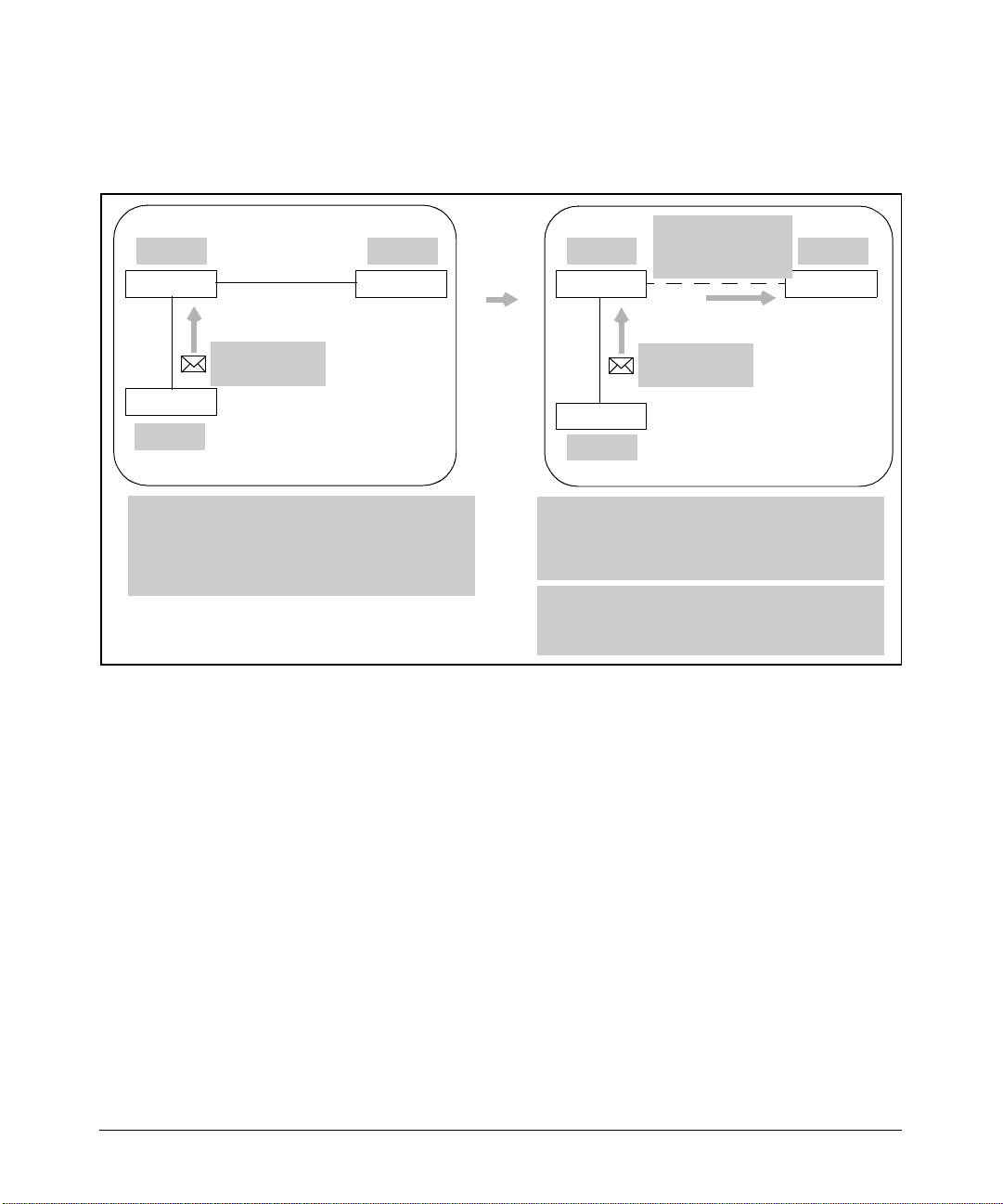
Configuring Backup WAN Connections
Determining a Backup Method
Figure 3-4 shows how a backup connection is established if demand routing is
configured. Figure 3-5 shows how a persistent backup connection is established.
10.1.1.0 10.4.4.0
Main Router
Switch
10.2.2.0
Routing Table
C 10.1.1.0/30 is directly connected, fr 1.1
C 10.2.2.0/24 is directly connected, eth 0/1
C 10.10.10.0/30 is directly connected, demand 1
S 10.4.4.0/24 [1/0] via 0.0.0.0, fr 1.1
Frame Relay
over E1
Office Router
To: 10.4.4.23
From: 10.2.2.5
Primary connection is av ailable, so
traffic is routed over Frame Relay
connection
Figure 3-4. Demand Routing for a Backup Connection
Primary
connection
fails
Connection
10.1.1.0 10.4.4.0
Main Router Office Router
Switch
10.2.2.0
Routing Table
C 10.2.2.0/24 is directly connected, eth 0/1
C 10.10.10.0/30 is directly connected, demand 1
S 10.4.4.0/24 [2/0] via 0.0.0.0, demand 1
ip access-list extended RouterA
permit ip 10.2.2.0 0.0.0.255 10.4.4.0 0.0.0.255
triggered by
interesting traffic
To: 10.4.4.23
From: 10.2.2.5
Primary connection is u navailable, so
traffic is routed to demand interface.
ACL determines which traffi c triggers
dial-up connection.
3-16
Page 97
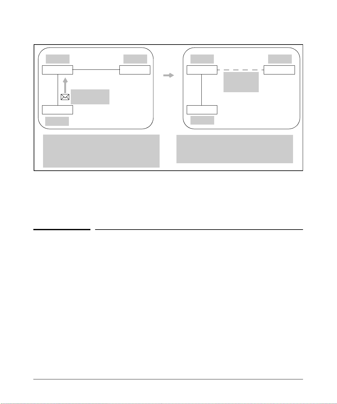
Configuring Demand Routing for Backup Connections
Configuring Backup WAN Connections
10.1.1.0 10.4.4.0
Main Router
Switch
10.2.2.0
Routing Table
C 10.1.1.0/30 is directly connected, fr 1.1
C 10.2.2.0/24 is directly connected, eth 0/1
C 10.10.10.0/30 is directly connected, ppp 1
S 10.4.4.0/24 [1/0] via 0.0.0.0, fr 1.1
Frame Relay
over E1
Office Router
To: 10.4.4.23
From: 10.2.2.5
Primary connection available, so
traffic is routed over Frame Relay
connection
Figure 3-5. Persistent Backup Connection
If you want to use demand routing for your backup connections, continue with
the next section. If you want a persistent backup connection, continue with
“Configuring a Persistent Backup Connection” on page 3-47.
Primary
connection
fails
10.1.1.0 10.4.4.0
Main Router Office Router
Connection
triggered
immediately
Switch
10.2.2.0
Routing Table
C 10.2.2.0/24 is directly connected, eth 0/1
C 10.10.10.0/30 is directly connected, ppp 1
S 10.4.4.0/24 [2/0] via 0.0.0.0, ppp 1
Primary connection unavailable,
so traffic is routed over dial-up
connection
Configuring Demand Routing for Backup
Connections
To configure demand routing for backup connections, you must complete the
following steps:
1. Create an extended access control list (ACL) to define the traffic that will
trigger the dial-up connection when the primary interface is unavailable.
2. Configure a demand interface.
3. Configure the BRI interface.
4. Create a floating static route to the far-end network.
3-17
Page 98

Configuring Backup WAN Connections
Configuring Demand Routing for Backup Connections
Define the Traffic That Triggers the Connection
You must first define the interesting traffic—the traffic that triggers, or activates, the WAN connection. For example, if you are configuring demand
routing for a backup connection between the main office and a branch office,
the interesting traffic would be the packets destined for the branch office. The
ProCurve Secure Router will route these packets to the demand interface only
if the primary interface is down and the floating static route that you configure
for the traffic is activated in the routing table. (Floating static routes are
explained in more depth later in this chapter.)
To define the interesting traffic, you create an extended ACL. The ProCurve
Secure Router will use this ACL to identify and select interesting traffic.
From the global configuration mode context, enter:
Syntax: ip access-list extended <listname>
Replace <listname> with an alphanumeric descriptor that is meaningful to
you. The listname is case sensitive.
After you enter this command, you are moved to the extended ACL configuration mode context and can enter permit and deny statements to define the
traffic that will trigger the dial-up connection. Use the following command
syntax:
3-18
Syntax: [permit | deny] <protocol> <source address> <source port> <destination
address> <destination port> [<packet bits>] [log | log-input]
Specifying a Protocol
When you create a permit or deny statement for an extended ACL, you must
always specify a protocol. Valid protocols include:
■ AHP
■ ESP
■ GRE
■ ICMP
■ IP
■ TCP
■ UDP
You can also specify a number between 0 and 255 for the protocol.
Page 99

Configuring Demand Routing for Backup Connections
Configuring Backup WAN Connections
For demand routing, you may want to create an ACL that selects all the traffic
to a particular subnet. In this case, you should specify ip as the protocol.
Defining the Source and Destination Addresses
When you create an extended ACL, you must configure both a source and a
destination address for each entry. You specify first the source address and
then the destination address, using the following syntax for each address:
[any | host <A.B.C.D> | hostname <hostname>] | <A.B.C.D> <wildcard bits>]
Table 3-2 lists the options you have for specifying a source or destination
address.
Table 3-2. Options for Specifying Source and Destination Addresses
Option Meaning
any match all hosts
host <A.B.C.D> specify a single IP address or a single host
hostname <hostname> specify a single host, using a hostname rather than an IP
address
<A.B.C.D> <wildcard bits> specify a range of IP addresses
Using Wildcard Bits. You use wildcard bits to permit or deny a range of IP
addresses. Wildcard bits define which address bits the Secure Router OS
should match and which address bits it should ignore.
When you enter wildcard bits, you use a zero to indicate that the Secure Router
OS should match the corresponding bit in the IP address. You use a one to
indicate that the Secure Router OS can ignore the corresponding bit in the IP
address. In other words, the Secure Router OS does not have to match that bit.
For example, you might enter:
ProCurve(config-ext-nacl)# deny ip any 192.115.1.0 0.0.0.255
If you enter 192.115.1.0 with the wildcard bits 0.0.0.255, the Secure Router
OS will not match any address bits in the fourth octet of the IP address. The
Secure Router OS will match incoming packets to the IP subnet with the
address 192.115.1.0 /24. (For more information about configuring ACLs, see
Chapter 5: Applying Access Control to Router Interfaces.)
3-19
Page 100

Configuring Backup WAN Connections
Configuring Demand Routing for Backup Connections
Examples. For example, if you want any traffic to the far-end network
192.168.115.0 /24 to trigger the dial-up connection, you would enter:
ProCurve(config-ext-nacl)# permit ip any 192.168.115.0 0.0.0.255
If you want any outbound traffic from a particular network segment to trigger
a dial-up connection, use wildcard bits to specify that network as the source.
For example, enter:
ProCurve(config-ext-nacl)# permit ip 192.168.1.0 0.0.0.255 any
Implicit “Deny Any” for ACL. Each ACL includes an implicit “deny any”
entry at the end of the list. If a packet does not match any entry in the ACL
you create, it matches the implicit “deny any” entry.
After you have finished creating the ACL, enter exit to return to the global
configuration mode context.
After you create the ACL, you must apply it to the demand interface. In fact,
the ACL will have no effect until you apply it to the demand interface.
Configuring the Demand Interface
You must create a demand interface for each router to which the ProCurve
Secure Router will connect through a dial-up connection. The demand interface provides the Data Link Layer for the physical dial-up interface.
Like other logical interfaces such as Frame Relay or PPP, the demand interface
controls the logical functions for the WAN connection. In many ways, you
configure the demand interface as you do any other logical interface. For
example, you assign the demand interface an IP address. From this interface,
you apply the ACL that defines the interesting traffic that triggers the dial-up
WAN connection.
The demand interface is different from other logical interfaces, however. For
one thing, the demand interface is not bound to a specific physical interface
or interfaces. Instead, the demand interface is associated with the pool of dialup interfaces used for backup.
The demand interface must also handle its status differently: it must always
be up, whether or not the physical dial-up interface associated with the
demand interface is up. Because the demand interface cannot actually be up
if the Physical Layer is down, it “spoofs” an up state. As a result, the demand
interface can be listed as a directly connected interface in the router’s routing
table, even when the dial-up interface is not in use.
3-20
 Loading...