

HP ProCurve Secure 7000dl, ProCurve 7102dl, ProCurve 7103dl Basic Management And Configuration Manual
Page 1

ProCurve Secure Router
7000dl Series
December 2005
J04_01
Basic Management and Configuration
Guide
Page 2

© Copyright 2005 Hewlett-Packard Development Company,
L.P. The information contained herein is subject to change without notice. All Rights Reserved.
This document contains proprietary information, w hi ch is
protected by copyright. No par t of th is document may be
photocopied, reproduced, or translated into another language
without the prior written consent of Hew lett-Packar d .
Publication Number
5991-3785
December 200 5
Applicable Products
ProCurve Secure Router 7102 dl (J8752A)
ProCurve Secure Router 7203 dl (J8753A)
Trademark Credit s
Microsoft, Windows, Windows NT, and Windows XP are U.S.
registered trademarks of Microsoft Corporation.
Disclaimer
The information contained in this document is subject to change
without notice.
HEWLETT -P ACKARD COMPANY MAKES NO WARRANTY
OF ANY KIND WITH REGARD TO THIS MATERIAL,
INCLUDING, BUT NOT LIMITED TO, THE IMPLIED
WARRANTIES OF MERCHANTABILITY AND FITNESS
FOR A PAR TICULAR PURPOSE. Hewlett-Packard shall not be
liable for errors contained herein or for incidental or consequential
damages in connection with the furni s hi ng, performance, or use
of this material.
The only warranties for HP products and services are set forth in
the express warranty statements accompanying such products and
services. Nothing herein should be c onst rue d as constituting an
additional warranty. HP shall not be liable for technical or editorial
errors or omissions contained herein.
Hewlett-Packard assumes no responsibility for the use or
reliability of its software on eq ui pment that is not furnished by
Hewlett-Packard.
Warranty
See the Customer Support/Warranty booklet included with the
product.
A copy of the specific warranty terms applicable to your HewlettPackard products and replacement parts can be obtained from your
HP Sales and Service Office or authorized dealer.
Hewlett-Packard Company
8000 Foothills Boulevard
Roseville, California 95747
http://www.procurve.com/
Page 3

Contents
1 Overview
Contents . . . . . . . . . . . . . . . . . . . . . . . . . . . . . . . . . . . . . . . . . . . . . . . . . . . . . . . 1-1
Using This Guide . . . . . . . . . . . . . . . . . . . . . . . . . . . . . . . . . . . . . . . . . . . . . . . 1-5
Understanding Command Syntax Statements . . . . . . . . . . . . . . . . . . . . 1-5
CLI Prompt . . . . . . . . . . . . . . . . . . . . . . . . . . . . . . . . . . . . . . . . . . . . . 1-6
IP Address Notation Convention . . . . . . . . . . . . . . . . . . . . . . . . . . . 1-7
Quick Starts . . . . . . . . . . . . . . . . . . . . . . . . . . . . . . . . . . . . . . . . . . . . . . . . 1-7
Obtaining Additional Information . . . . . . . . . . . . . . . . . . . . . . . . . . . . . . 1-7
Downloading Software Updates . . . . . . . . . . . . . . . . . . . . . . . . . . . . . . . 1-8
Interface Management Options . . . . . . . . . . . . . . . . . . . . . . . . . . . . . . . . . . 1-10
CLI . . . . . . . . . . . . . . . . . . . . . . . . . . . . . . . . . . . . . . . . . . . . . . . . . . . . . . . 1-10
Web Browser Interface . . . . . . . . . . . . . . . . . . . . . . . . . . . . . . . . . . . . . . 1-10
Accessing the Web Browser Interface . . . . . . . . . . . . . . . . . . . . . 1-11
Using the ProCurve Web Browser Interface . . . . . . . . . . . . . . . . 1-12
Hardware Overview . . . . . . . . . . . . . . . . . . . . . . . . . . . . . . . . . . . . . . . . . . . . 1-13
ProCurve Secure Router Front Panel . . . . . . . . . . . . . . . . . . . . . . . . . . 1-13
Console Port . . . . . . . . . . . . . . . . . . . . . . . . . . . . . . . . . . . . . . . . . . . . . . 1-13
Ethernet Ports . . . . . . . . . . . . . . . . . . . . . . . . . . . . . . . . . . . . . . . . . . . . . 1-14
Slots . . . . . . . . . . . . . . . . . . . . . . . . . . . . . . . . . . . . . . . . . . . . . . . . . . . . . . 1-14
E1 and T1 Modules . . . . . . . . . . . . . . . . . . . . . . . . . . . . . . . . . . . . . . 1-16
ISDN Module . . . . . . . . . . . . . . . . . . . . . . . . . . . . . . . . . . . . . . . . . . . 1-18
Backup Modules . . . . . . . . . . . . . . . . . . . . . . . . . . . . . . . . . . . . . . . . 1-19
Wide-Slot Option Modules . . . . . . . . . . . . . . . . . . . . . . . . . . . . . . . 1-20
Interface Numbering Conventions . . . . . . . . . . . . . . . . . . . . . . . . . . . . 1-22
Status LEDs . . . . . . . . . . . . . . . . . . . . . . . . . . . . . . . . . . . . . . . . . . . . . . . 1-23
Power LED . . . . . . . . . . . . . . . . . . . . . . . . . . . . . . . . . . . . . . . . . . . . 1-23
Fault LED . . . . . . . . . . . . . . . . . . . . . . . . . . . . . . . . . . . . . . . . . . . . . 1-23
i
Page 4

LEDs for Slots 1 and 2 . . . . . . . . . . . . . . . . . . . . . . . . . . . . . . . . . . . . . . 1-24
Status LEDs . . . . . . . . . . . . . . . . . . . . . . . . . . . . . . . . . . . . . . . . . . . . 1-24
Backup LEDs . . . . . . . . . . . . . . . . . . . . . . . . . . . . . . . . . . . . . . . . . . 1-25
Tx and Rx LEDs . . . . . . . . . . . . . . . . . . . . . . . . . . . . . . . . . . . . . . . . 1-25
Slot 3 LEDs . . . . . . . . . . . . . . . . . . . . . . . . . . . . . . . . . . . . . . . . . . . . . . . . 1-25
Status LED . . . . . . . . . . . . . . . . . . . . . . . . . . . . . . . . . . . . . . . . . . . . 1-26
Activity LED . . . . . . . . . . . . . . . . . . . . . . . . . . . . . . . . . . . . . . . . . . . 1-26
Test LED . . . . . . . . . . . . . . . . . . . . . . . . . . . . . . . . . . . . . . . . . . . . . . 1-26
Ethernet and Activity LEDs . . . . . . . . . . . . . . . . . . . . . . . . . . . . . . . . . . 1-26
Activity LEDs . . . . . . . . . . . . . . . . . . . . . . . . . . . . . . . . . . . . . . . . . . 1-27
Link LEDs . . . . . . . . . . . . . . . . . . . . . . . . . . . . . . . . . . . . . . . . . . . . . 1-27
Rear Panel . . . . . . . . . . . . . . . . . . . . . . . . . . . . . . . . . . . . . . . . . . . . . . . . 1-27
Optional IPSec VPN Module . . . . . . . . . . . . . . . . . . . . . . . . . . . . . . 1-27
Compact Flash Card . . . . . . . . . . . . . . . . . . . . . . . . . . . . . . . . . . . . 1-28
Redundant Power Source . . . . . . . . . . . . . . . . . . . . . . . . . . . . . . . . 1-29
Memory . . . . . . . . . . . . . . . . . . . . . . . . . . . . . . . . . . . . . . . . . . . . . . . . . . . 1-29
Software Overview . . . . . . . . . . . . . . . . . . . . . . . . . . . . . . . . . . . . . . . . . . . . . 1-30
Bootup Process . . . . . . . . . . . . . . . . . . . . . . . . . . . . . . . . . . . . . . . . . . . . 1-30
Advantages of Booting From Compact Flash . . . . . . . . . . . . . . . . 1-32
Setting Up a Compact Flash Card
From Which to Boot the Router . . . . . . . . . . . . . . . . . . . . . . . . . . . 1-33
Saving Configuration Changes . . . . . . . . . . . . . . . . . . . . . . . . . . . . 1-33
AutoSynch™ Technology . . . . . . . . . . . . . . . . . . . . . . . . . . . . . . . . . . . . 1-34
Secure Router OS Hierarchy . . . . . . . . . . . . . . . . . . . . . . . . . . . . . . . . . 1-34
Basic Mode . . . . . . . . . . . . . . . . . . . . . . . . . . . . . . . . . . . . . . . . . . . . 1-36
Enable Mode . . . . . . . . . . . . . . . . . . . . . . . . . . . . . . . . . . . . . . . . . . . 1-36
Global Configuration Mode . . . . . . . . . . . . . . . . . . . . . . . . . . . . . . 1-37
Commands Available in the Basic, Enable,
or Global Configuration Mode Contexts . . . . . . . . . . . . . . . . . . . . 1-39
Basic Mode Commands . . . . . . . . . . . . . . . . . . . . . . . . . . . . . . . . . . . . . 1-39
Clear . . . . . . . . . . . . . . . . . . . . . . . . . . . . . . . . . . . . . . . . . . . . . . . . . . 1-39
Enable . . . . . . . . . . . . . . . . . . . . . . . . . . . . . . . . . . . . . . . . . . . . . . . . 1-39
Logout . . . . . . . . . . . . . . . . . . . . . . . . . . . . . . . . . . . . . . . . . . . . . . . . 1-40
Ping . . . . . . . . . . . . . . . . . . . . . . . . . . . . . . . . . . . . . . . . . . . . . . . . . . 1-40
Show . . . . . . . . . . . . . . . . . . . . . . . . . . . . . . . . . . . . . . . . . . . . . . . . . 1-41
ii
Page 5

Telnet . . . . . . . . . . . . . . . . . . . . . . . . . . . . . . . . . . . . . . . . . . . . . . . . . 1-42
Traceroute . . . . . . . . . . . . . . . . . . . . . . . . . . . . . . . . . . . . . . . . . . . . . 1-42
Terminal . . . . . . . . . . . . . . . . . . . . . . . . . . . . . . . . . . . . . . . . . . . . . . 1-43
Wall . . . . . . . . . . . . . . . . . . . . . . . . . . . . . . . . . . . . . . . . . . . . . . . . . . 1-43
Enable Mode Commands . . . . . . . . . . . . . . . . . . . . . . . . . . . . . . . . . . . . 1-43
Clear . . . . . . . . . . . . . . . . . . . . . . . . . . . . . . . . . . . . . . . . . . . . . . . . . . 1-44
Clock . . . . . . . . . . . . . . . . . . . . . . . . . . . . . . . . . . . . . . . . . . . . . . . . . 1-45
Configure . . . . . . . . . . . . . . . . . . . . . . . . . . . . . . . . . . . . . . . . . . . . . . 1-46
Copy . . . . . . . . . . . . . . . . . . . . . . . . . . . . . . . . . . . . . . . . . . . . . . . . . . 1-46
Debug . . . . . . . . . . . . . . . . . . . . . . . . . . . . . . . . . . . . . . . . . . . . . . . . . 1-49
Dir . . . . . . . . . . . . . . . . . . . . . . . . . . . . . . . . . . . . . . . . . . . . . . . . . . . 1-49
Disable . . . . . . . . . . . . . . . . . . . . . . . . . . . . . . . . . . . . . . . . . . . . . . . . 1-50
Erase . . . . . . . . . . . . . . . . . . . . . . . . . . . . . . . . . . . . . . . . . . . . . . . . . 1-50
Events . . . . . . . . . . . . . . . . . . . . . . . . . . . . . . . . . . . . . . . . . . . . . . . . 1-51
Reload . . . . . . . . . . . . . . . . . . . . . . . . . . . . . . . . . . . . . . . . . . . . . . . . 1-51
Show . . . . . . . . . . . . . . . . . . . . . . . . . . . . . . . . . . . . . . . . . . . . . . . . . 1-51
Undebug . . . . . . . . . . . . . . . . . . . . . . . . . . . . . . . . . . . . . . . . . . . . . . 1-56
Write . . . . . . . . . . . . . . . . . . . . . . . . . . . . . . . . . . . . . . . . . . . . . . . . . 1-56
show tech . . . . . . . . . . . . . . . . . . . . . . . . . . . . . . . . . . . . . . . . . . . . . 1-57
Updating the Boot Code . . . . . . . . . . . . . . . . . . . . . . . . . . . . . . . . . 1-59
Global Configuration Mode Commands . . . . . . . . . . . . . . . . . . . . . . . . 1-60
hostname Command . . . . . . . . . . . . . . . . . . . . . . . . . . . . . . . . . . . . 1-60
autosynch Command . . . . . . . . . . . . . . . . . . . . . . . . . . . . . . . . . . . . 1-60
Support for SNMP . . . . . . . . . . . . . . . . . . . . . . . . . . . . . . . . . . . . . . 1-61
SafeMode . . . . . . . . . . . . . . . . . . . . . . . . . . . . . . . . . . . . . . . . . . . . . . 1-61
Help Tools . . . . . . . . . . . . . . . . . . . . . . . . . . . . . . . . . . . . . . . . . . . . . . . . . . . . 1-64
CLI Help Commands . . . . . . . . . . . . . . . . . . . . . . . . . . . . . . . . . . . . 1-64
Editing Commands . . . . . . . . . . . . . . . . . . . . . . . . . . . . . . . . . . . . . . 1-64
no . . . . . . . . . . . . . . . . . . . . . . . . . . . . . . . . . . . . . . . . . . . . . . . . . . . . 1-66
do . . . . . . . . . . . . . . . . . . . . . . . . . . . . . . . . . . . . . . . . . . . . . . . . . . . . 1-66
exit . . . . . . . . . . . . . . . . . . . . . . . . . . . . . . . . . . . . . . . . . . . . . . . . . . . 1-66
Bootstrap Mode Context . . . . . . . . . . . . . . . . . . . . . . . . . . . . . . . . . . . . 1-66
iii
Page 6

Troubleshooting . . . . . . . . . . . . . . . . . . . . . . . . . . . . . . . . . . . . . . . . . . . . . . . 1-70
Compact Flash . . . . . . . . . . . . . . . . . . . . . . . . . . . . . . . . . . . . . . . . . . . . . 1-70
AutoSynch™ Error Messages . . . . . . . . . . . . . . . . . . . . . . . . . . . . . . . . 1-70
Using the reload in Command . . . . . . . . . . . . . . . . . . . . . . . . . . . . . . . . 1-72
Managing Configuration Files Using a Text Editor . . . . . . . . . . . . . . . . . . 1-73
Creating and Transferring Configuration Files . . . . . . . . . . . . . . . . . . 1-75
Configuration File Transfer Using the Console Port . . . . . . . . . . 1-76
Configuration File Transfer Using a TFTP Server . . . . . . . . . . . . 1-78
Configuration File Transfer Using
a Compact Flash Card . . . . . . . . . . . . . . . . . . . . . . . . . . . . . . . . . . . 1-81
Quick Start . . . . . . . . . . . . . . . . . . . . . . . . . . . . . . . . . . . . . . . . . . . . . . . . . . . . 1-83
Accessing the Secure Router OS . . . . . . . . . . . . . . . . . . . . . . . . . . . . . . 1-83
2 Controlling Management Access to the ProCurve Secure
Router
Contents . . . . . . . . . . . . . . . . . . . . . . . . . . . . . . . . . . . . . . . . . . . . . . . . . . . . . . . 2-1
Securing Management Access to the ProCurve Secure Router . . . . . . . . . 2-4
Restricting Access to the Enable Mode Context . . . . . . . . . . . . . . . . . . 2-4
Configuring a Password for Console Access . . . . . . . . . . . . . . . . . . . . . 2-5
Enabling Remote Access to the ProCurve Secure Router . . . . . . . . . . 2-6
Configuring an Ethernet Interface . . . . . . . . . . . . . . . . . . . . . . . . . . 2-7
Configuring Telnet Access . . . . . . . . . . . . . . . . . . . . . . . . . . . . . . . . . . . . 2-8
Configuring Local User Lists . . . . . . . . . . . . . . . . . . . . . . . . . . . . . . . . . 2-10
Encrypting All the Passwords Configured on the Router . . . . . . 2-11
Enabling Access to the Web Browser Interface . . . . . . . . . . . . . . 2-11
Managing SSH Communications . . . . . . . . . . . . . . . . . . . . . . . . . . 2-12
Using FTP to Access the Router . . . . . . . . . . . . . . . . . . . . . . . . . . 2-13
Using the Local User List for Console or Telnet Access . . . . . . . 2-13
Enabling Secure Copy Server . . . . . . . . . . . . . . . . . . . . . . . . . . . . . . . . 2-13
Viewing Information about Users . . . . . . . . . . . . . . . . . . . . . . . . . . . . . 2-14
Using the AAA Subsystem to Control Management Access . . . . . . . . . . . 2-14
Advantages of Using the AAA Subsystem . . . . . . . . . . . . . . . . . . . . . . 2-15
Enabling the AAA Subsystem . . . . . . . . . . . . . . . . . . . . . . . . . . . . . . . . 2-15
iv
Page 7

Configuring AAA for Authentication . . . . . . . . . . . . . . . . . . . . . . . . . . 2-16
Creating a Named List for the Enable Mode
Authentication . . . . . . . . . . . . . . . . . . . . . . . . . . . . . . . . . . . . . . . . . 2-16
Creating a Named List for User Authentication . . . . . . . . . . . . . . 2-18
Criteria for Failure of Authentication Methods . . . . . . . . . . . . . . 2-19
Assign the Named List . . . . . . . . . . . . . . . . . . . . . . . . . . . . . . . . . . . 2-20
Options for AAA Authentication: Configuring
Banners, Messages, and Prompts . . . . . . . . . . . . . . . . . . . . . . . . . . 2-21
Configuring Authorization . . . . . . . . . . . . . . . . . . . . . . . . . . . . . . . . . . . 2-23
Define a Named List for Authorization . . . . . . . . . . . . . . . . . . . . . 2-23
Assign the Named List . . . . . . . . . . . . . . . . . . . . . . . . . . . . . . . . . . . 2-24
Enable Authorization Commands for Console Line . . . . . . . . . . 2-24
Configuring the TACACS+ Server for Accounting . . . . . . . . . . . . . . . 2-25
Configuring a Named List for Accounting . . . . . . . . . . . . . . . . . . 2-25
Assign the Named List . . . . . . . . . . . . . . . . . . . . . . . . . . . . . . . . . . . 2-26
Configure Update Settings . . . . . . . . . . . . . . . . . . . . . . . . . . . . . . . 2-26
Do Not Send Records for Null Users . . . . . . . . . . . . . . . . . . . . . . . 2-27
Configuring a RADIUS Server for Authentication . . . . . . . . . . . . . . . 2-27
Define the RADIUS Server . . . . . . . . . . . . . . . . . . . . . . . . . . . . . . . 2-27
Define a Group of RADIUS Servers . . . . . . . . . . . . . . . . . . . . . . . . 2-29
Configure Global Settings for RADIUS Servers . . . . . . . . . . . . . . 2-30
Configuring the TACACS+ Server . . . . . . . . . . . . . . . . . . . . . . . . . . . . . 2-31
Define the TACACS+ Server . . . . . . . . . . . . . . . . . . . . . . . . . . . . . . 2-31
Creating a TACACS+ Group . . . . . . . . . . . . . . . . . . . . . . . . . . . . . . 2-33
Configure Global Settings for TACACS+ Servers . . . . . . . . . . . . 2-34
Troubleshooting AAA . . . . . . . . . . . . . . . . . . . . . . . . . . . . . . . . . . . . . . . . . . . 2-35
debug aaa Command . . . . . . . . . . . . . . . . . . . . . . . . . . . . . . . . . . . . . . . . 2-35
Troubleshooting the RADIUS Server . . . . . . . . . . . . . . . . . . . . . . . . . . 2-36
debug radius Command . . . . . . . . . . . . . . . . . . . . . . . . . . . . . . . . . 2-37
Troubleshooting the TACACS+ Server . . . . . . . . . . . . . . . . . . . . . . . . . 2-37
Port Authentication . . . . . . . . . . . . . . . . . . . . . . . . . . . . . . . . . . . . . . . . . . . . 2-40
Enabling Supplicant Functionality . . . . . . . . . . . . . . . . . . . . . . . . . . . . 2-40
Troubleshooting Supplicant Functionality . . . . . . . . . . . . . . . . . . . . . 2-41
v
Page 8

Quick Start . . . . . . . . . . . . . . . . . . . . . . . . . . . . . . . . . . . . . . . . . . . . . . . . . . . . 2-42
Configure the Enable Mode Password . . . . . . . . . . . . . . . . . . . . . . . . . 2-42
Configure a Password for the Console Access . . . . . . . . . . . . . . . . . . 2-42
Configuring Remote Access to the ProCurve Secure Router . . . . . . 2-43
Configuring an Ethernet Interface . . . . . . . . . . . . . . . . . . . . . . . . . 2-43
Configuring a Password for Telnet Access . . . . . . . . . . . . . . . . . . 2-44
Configuring Local User Lists . . . . . . . . . . . . . . . . . . . . . . . . . . . . . 2-45
Configuring AAA . . . . . . . . . . . . . . . . . . . . . . . . . . . . . . . . . . . . . . . . . . . 2-45
Configuring Authentication with AAA . . . . . . . . . . . . . . . . . . . . . . 2-46
Configuring Authorization with AAA . . . . . . . . . . . . . . . . . . . . . . . 2-46
Configuring the TACACS+ Server for Accounting . . . . . . . . . . . . 2-47
Defining a RADIUS Server . . . . . . . . . . . . . . . . . . . . . . . . . . . . . . . 2-48
Defining a TACACS+ Server . . . . . . . . . . . . . . . . . . . . . . . . . . . . . . 2-48
Enabling 802.1X Supplicant Status . . . . . . . . . . . . . . . . . . . . . . . . . . . . 2-48
3 Configuring Ethernet Interfaces
Contents . . . . . . . . . . . . . . . . . . . . . . . . . . . . . . . . . . . . . . . . . . . . . . . . . . . . . . . 3-1
Ethernet Interfaces . . . . . . . . . . . . . . . . . . . . . . . . . . . . . . . . . . . . . . . . . . . . . . 3-2
Configuring the Ethernet Interface . . . . . . . . . . . . . . . . . . . . . . . . . . . . . 3-3
Enabling the Ethernet Interface . . . . . . . . . . . . . . . . . . . . . . . . . . . . . . . 3-4
Configuring an IP Address . . . . . . . . . . . . . . . . . . . . . . . . . . . . . . . . . . . . 3-5
Assigning a Static IP Address . . . . . . . . . . . . . . . . . . . . . . . . . . . . . . 3-5
Configuring the Ethernet Interface as a DHCP Client . . . . . . . . . . 3-5
Configuring the Ethernet Interface as
an Unnumbered Interface . . . . . . . . . . . . . . . . . . . . . . . . . . . . . . . . . 3-9
Setting the Speed and the Duplex Settings . . . . . . . . . . . . . . . . . . . . . 3-10
Configuring the Line for Half-Duplex or Full-Duplex . . . . . . . . . . . . . 3-11
Setting the MTU . . . . . . . . . . . . . . . . . . . . . . . . . . . . . . . . . . . . . . . . . . . . 3-11
Adding a Description . . . . . . . . . . . . . . . . . . . . . . . . . . . . . . . . . . . . . . . 3-12
Summary of Ethernet Configuration Settings . . . . . . . . . . . . . . . . . . . 3-13
Configure VLAN Support . . . . . . . . . . . . . . . . . . . . . . . . . . . . . . . . . . . . . . . . 3-15
Configuring VLAN Support . . . . . . . . . . . . . . . . . . . . . . . . . . . . . . . 3-17
Assigning an IP Address . . . . . . . . . . . . . . . . . . . . . . . . . . . . . . . . . 3-19
vi
Page 9

Viewing the Status of Ethernet Interfaces or Subinterfaces . . . . . . . . . . . 3-19
show interfaces Command . . . . . . . . . . . . . . . . . . . . . . . . . . . . . . . . . . . 3-19
show running-config Commands . . . . . . . . . . . . . . . . . . . . . . . . . . . . . . 3-21
Viewing the Configurations That Have Been Entered . . . . . . . . . 3-22
Viewing All the Configuration Settings
Including Defaults . . . . . . . . . . . . . . . . . . . . . . . . . . . . . . . . . . . . . . 3-22
Troubleshooting an Ethernet Interface . . . . . . . . . . . . . . . . . . . . . . . . . . . . 3-24
show event-history Command . . . . . . . . . . . . . . . . . . . . . . . . . . . . . . . . 3-25
debug interface ethernet Command . . . . . . . . . . . . . . . . . . . . . . . . . . . 3-25
Quick Start . . . . . . . . . . . . . . . . . . . . . . . . . . . . . . . . . . . . . . . . . . . . . . . . . . . . 3-26
Configuring the Ethernet Interface . . . . . . . . . . . . . . . . . . . . . . . . . . . . 3-26
4 Configuring E1 and T1 Interfaces
Contents . . . . . . . . . . . . . . . . . . . . . . . . . . . . . . . . . . . . . . . . . . . . . . . . . . . . . . . 4-1
Overview of E1 and T1 WAN Connections . . . . . . . . . . . . . . . . . . . . . . . . . . 4-3
Elements of an E1- or T1-Carrier Line . . . . . . . . . . . . . . . . . . . . . . . . . . 4-3
Connecting Your Premises to the Public Carrier: the Local Loop . . . 4-4
External or Built-in CSU/DSU . . . . . . . . . . . . . . . . . . . . . . . . . . . . . 4-6
ProCurve Secure Router Modules . . . . . . . . . . . . . . . . . . . . . . . . . . . . . . . . . 4-8
E1 Modules with a Built-in DSU . . . . . . . . . . . . . . . . . . . . . . . . . . . . . . . 4-8
Supported Standards . . . . . . . . . . . . . . . . . . . . . . . . . . . . . . . . . . . . . 4-8
T1 Modules with a Built-in CSU/DSU . . . . . . . . . . . . . . . . . . . . . . . . . . . 4-9
Supported Standards . . . . . . . . . . . . . . . . . . . . . . . . . . . . . . . . . . . . . 4-9
E1 or T1 Interfaces: Configuring the Physical Layer . . . . . . . . . . . . . 4-10
E1 or T1 Interface Configuration Mode Context . . . . . . . . . . . . . 4-11
Channels . . . . . . . . . . . . . . . . . . . . . . . . . . . . . . . . . . . . . . . . . . . . . . 4-12
Line Coding . . . . . . . . . . . . . . . . . . . . . . . . . . . . . . . . . . . . . . . . . . . . 4-14
Frame Format . . . . . . . . . . . . . . . . . . . . . . . . . . . . . . . . . . . . . . . . . . 4-15
Clock Source, or Timing, for the E1- or T1-Carrier Line . . . . . . . 4-17
Transmit Signal Level (T1 Interfaces Only) . . . . . . . . . . . . . . . . . 4-18
Set the FDL (T1 Interfaces Only) . . . . . . . . . . . . . . . . . . . . . . . . . . 4-19
Activate the E1 or T1 Interface . . . . . . . . . . . . . . . . . . . . . . . . . . . 4-20
Threshold Commands . . . . . . . . . . . . . . . . . . . . . . . . . . . . . . . . . . . . . . . 4-21
Types of Line Errors . . . . . . . . . . . . . . . . . . . . . . . . . . . . . . . . . . . . 4-22
vii
Page 10

Viewing Information about E1 and T1 Interfaces . . . . . . . . . . . . . . . . . . . 4-26
show interfaces Command . . . . . . . . . . . . . . . . . . . . . . . . . . . . . . . . . . . 4-27
show running-config Command . . . . . . . . . . . . . . . . . . . . . . . . . . . . . . 4-28
show running-config verbose Command . . . . . . . . . . . . . . . . . . . . . . . 4-29
Troubleshooting E1 and T1 WAN Connections . . . . . . . . . . . . . . . . . . . . . 4-30
No Light . . . . . . . . . . . . . . . . . . . . . . . . . . . . . . . . . . . . . . . . . . . . . . . 4-32
Red Light . . . . . . . . . . . . . . . . . . . . . . . . . . . . . . . . . . . . . . . . . . . . . . 4-32
Yellow Light . . . . . . . . . . . . . . . . . . . . . . . . . . . . . . . . . . . . . . . . . . . 4-34
Green Light . . . . . . . . . . . . . . . . . . . . . . . . . . . . . . . . . . . . . . . . . . . . 4-35
Viewing Performance Statistics . . . . . . . . . . . . . . . . . . . . . . . . . . . . . . . 4-35
Quick Start . . . . . . . . . . . . . . . . . . . . . . . . . . . . . . . . . . . . . . . . . . . . . . . . . . . . 4-37
Configuring an E1 or T1 Interface . . . . . . . . . . . . . . . . . . . . . . . . . . . . . 4-38
5 Configuring Serial Interfaces for E1- and T1-Carrier Lines
Contents . . . . . . . . . . . . . . . . . . . . . . . . . . . . . . . . . . . . . . . . . . . . . . . . . . . . . . . 5-1
Using the Serial Module for E1- or T1-Carrier Lines . . . . . . . . . . . . . . . . . . 5-3
Elements of an E1- or T1-Carrier Line . . . . . . . . . . . . . . . . . . . . . . . . . . 5-3
Connecting Your Premises to the Public Carrier’s
Central Office: the Local Loop . . . . . . . . . . . . . . . . . . . . . . . . . . . . . . . . . 5-4
External or Built-in CSU/DSU . . . . . . . . . . . . . . . . . . . . . . . . . . . . . 5-6
Serial Module for the ProCurve Secure Router . . . . . . . . . . . . . . . . . . . 5-7
Standards Supported by the Serial Module . . . . . . . . . . . . . . . . . . 5-7
viii
Serial Interface: Configuring the Physical Layer . . . . . . . . . . . . . . . . . . . . . 5-8
Making the Physical Connection . . . . . . . . . . . . . . . . . . . . . . . . . . . . . . . 5-8
Serial Interface Configuration Mode Context . . . . . . . . . . . . . . . . . . . 5-12
Configuring the Interface for the Appropriate Cable . . . . . . . . . . . . . 5-12
Configuring the Clock Source . . . . . . . . . . . . . . . . . . . . . . . . . . . . . . . . 5-13
Inverting et-clock . . . . . . . . . . . . . . . . . . . . . . . . . . . . . . . . . . . . . . . 5-13
Inverting txclock or rxclock . . . . . . . . . . . . . . . . . . . . . . . . . . . . . . 5-13
Activating the Serial Interface . . . . . . . . . . . . . . . . . . . . . . . . . . . . . . . . 5-14
Configuring the Data Link Layer Protocol . . . . . . . . . . . . . . . . . . . . . . 5-14
Page 11

Viewing Information about the Serial Interface . . . . . . . . . . . . . . . . . . . . . 5-15
show interfaces serial Command . . . . . . . . . . . . . . . . . . . . . . . . . . . . . 5-15
show running-config interface Command . . . . . . . . . . . . . . . . . . . . . . 5-16
View All the WAN Connections Configured on the Router . . . . . . . . 5-17
Troubleshooting a Serial Connection . . . . . . . . . . . . . . . . . . . . . . . . . . . . . 5-17
Checking the LED for the Serial Module . . . . . . . . . . . . . . . . . . . . . . . 5-18
No Light . . . . . . . . . . . . . . . . . . . . . . . . . . . . . . . . . . . . . . . . . . . . . . . 5-19
Red Light . . . . . . . . . . . . . . . . . . . . . . . . . . . . . . . . . . . . . . . . . . . . . . 5-19
Yellow Light . . . . . . . . . . . . . . . . . . . . . . . . . . . . . . . . . . . . . . . . . . . 5-20
Green Light . . . . . . . . . . . . . . . . . . . . . . . . . . . . . . . . . . . . . . . . . . . . 5-21
Solving a Specific Problem: the Line Between the Serial Module
and the CSU/DSU Keeps Going Down . . . . . . . . . . . . . . . . . . . . . . . . . 5-21
Quick Start . . . . . . . . . . . . . . . . . . . . . . . . . . . . . . . . . . . . . . . . . . . . . . . . . . . . 5-22
Configure a Serial Interface . . . . . . . . . . . . . . . . . . . . . . . . . . . . . . . . . . 5-22
6 Configuring the Data Link Layer Protocol for E1, T1, and
Serial Interfaces
Contents . . . . . . . . . . . . . . . . . . . . . . . . . . . . . . . . . . . . . . . . . . . . . . . . . . . . . . . 6-1
Configuring the Logical Interface . . . . . . . . . . . . . . . . . . . . . . . . . . . . . . . . . . 6-3
PPP Overview . . . . . . . . . . . . . . . . . . . . . . . . . . . . . . . . . . . . . . . . . . . . . . 6-4
Establishing a PPP Connection . . . . . . . . . . . . . . . . . . . . . . . . . . . . 6-4
Creating a PPP Interface on the ProCurve Secure Router . . . . . . 6-6
Configuring an IP Address for the WAN Connection . . . . . . . . . . 6-8
Activating the PPP Interface . . . . . . . . . . . . . . . . . . . . . . . . . . . . . . 6-10
Binding the Physical Interface to the Logical Interface . . . . . . . 6-10
PPP Authentication . . . . . . . . . . . . . . . . . . . . . . . . . . . . . . . . . . . . . 6-11
Additional Settings . . . . . . . . . . . . . . . . . . . . . . . . . . . . . . . . . . . . . . 6-16
Settings Explained in Other Chapters . . . . . . . . . . . . . . . . . . . . . . 6-18
Frame Relay Overview . . . . . . . . . . . . . . . . . . . . . . . . . . . . . . . . . . . . . . 6-19
Packet-Switching Network . . . . . . . . . . . . . . . . . . . . . . . . . . . . . . . 6-20
Components of a Frame Relay Network . . . . . . . . . . . . . . . . . . . . 6-21
DLCI . . . . . . . . . . . . . . . . . . . . . . . . . . . . . . . . . . . . . . . . . . . . . . . . . . 6-22
Create the Frame Relay Interface . . . . . . . . . . . . . . . . . . . . . . . . . 6-23
Activate the Frame Relay Interface . . . . . . . . . . . . . . . . . . . . . . . . 6-25
Define the Signaling Role . . . . . . . . . . . . . . . . . . . . . . . . . . . . . . . . 6-25
ix
Page 12

Define the Frame Relay Signaling Type . . . . . . . . . . . . . . . . . . . . 6-26
Configure Frame-Relay Counters . . . . . . . . . . . . . . . . . . . . . . . . . 6-26
Create the Frame Relay Subinterface . . . . . . . . . . . . . . . . . . . . . . 6-28
Assign a DLCI to the Frame Relay Subinterface . . . . . . . . . . . . . 6-28
Configure the IP Address for the WAN Connection . . . . . . . . . . 6-29
Set the CIR . . . . . . . . . . . . . . . . . . . . . . . . . . . . . . . . . . . . . . . . . . . . 6-33
Set the EIR . . . . . . . . . . . . . . . . . . . . . . . . . . . . . . . . . . . . . . . . . . . . 6-34
Bind the Physical Interface to the Logical Interface . . . . . . . . . . 6-35
Additional Settings . . . . . . . . . . . . . . . . . . . . . . . . . . . . . . . . . . . . . . 6-36
Settings Explained in Other Chapters . . . . . . . . . . . . . . . . . . . . . . 6-38
Configuring HDLC as the Data Link Layer Protocol . . . . . . . . . . . . . . 6-39
Create the HDLC Interface . . . . . . . . . . . . . . . . . . . . . . . . . . . . . . . 6-39
Activate the HDLC Interface . . . . . . . . . . . . . . . . . . . . . . . . . . . . . . 6-41
Configure an IP Address for the WAN Connection . . . . . . . . . . . 6-41
Bind the Physical Interface to the Logical Interface . . . . . . . . . . 6-43
Additional Settings . . . . . . . . . . . . . . . . . . . . . . . . . . . . . . . . . . . . . . 6-44
Settings Explained in Other Chapters . . . . . . . . . . . . . . . . . . . . . . 6-46
Example Networks . . . . . . . . . . . . . . . . . . . . . . . . . . . . . . . . . . . . . . . . . . . . . 6-46
Checking the Status of Logical Interfaces . . . . . . . . . . . . . . . . . . . . . . . . . . 6-53
View the Status of Interfaces . . . . . . . . . . . . . . . . . . . . . . . . . . . . . . . . . 6-53
Viewing the Status of PPP Interfaces . . . . . . . . . . . . . . . . . . . . . . 6-53
Viewing the Status of Frame Relay Interfaces
and Subinterfaces . . . . . . . . . . . . . . . . . . . . . . . . . . . . . . . . . . . . . . 6-55
Viewing the Status of HDLC Interfaces . . . . . . . . . . . . . . . . . . . . . 6-57
Viewing Configuration Information . . . . . . . . . . . . . . . . . . . . . . . . 6-57
Troubleshooting Logical Interfaces . . . . . . . . . . . . . . . . . . . . . . . . . . . . . . . 6-58
Troubleshooting the PPP Interface . . . . . . . . . . . . . . . . . . . . . . . . . . . . 6-58
Troubleshooting PPP Authentication . . . . . . . . . . . . . . . . . . . . . . 6-62
Troubleshooting the Frame Relay Interface . . . . . . . . . . . . . . . . . . . . 6-65
Troubleshooting HDLC . . . . . . . . . . . . . . . . . . . . . . . . . . . . . . . . . . . . . . 6-69
x
Page 13

Quick Start . . . . . . . . . . . . . . . . . . . . . . . . . . . . . . . . . . . . . . . . . . . . . . . . . . . . 6-70
PPP . . . . . . . . . . . . . . . . . . . . . . . . . . . . . . . . . . . . . . . . . . . . . . . . . . . . . . 6-70
PPP Authentication . . . . . . . . . . . . . . . . . . . . . . . . . . . . . . . . . . . . . . . . . 6-71
Requiring the Peer to Authenticate Itself . . . . . . . . . . . . . . . . . . . 6-72
Authenticating to a Peer . . . . . . . . . . . . . . . . . . . . . . . . . . . . . . . . . 6-72
Frame Relay . . . . . . . . . . . . . . . . . . . . . . . . . . . . . . . . . . . . . . . . . . . . . . . 6-73
HDLC . . . . . . . . . . . . . . . . . . . . . . . . . . . . . . . . . . . . . . . . . . . . . . . . . . . . . 6-75
7 ADSL WAN Connections
Contents . . . . . . . . . . . . . . . . . . . . . . . . . . . . . . . . . . . . . . . . . . . . . . . . . . . . . . . 7-1
ADSL Overview . . . . . . . . . . . . . . . . . . . . . . . . . . . . . . . . . . . . . . . . . . . . . . . . . 7-4
ADSL Technologies . . . . . . . . . . . . . . . . . . . . . . . . . . . . . . . . . . . . . . . . . . 7-5
ADSL2 and ADSL2+: Enhancing Transmission Speeds . . . . . . . . 7-5
READSL: Supporting Greater Distances . . . . . . . . . . . . . . . . . . . . . 7-6
Elements of an ADSL Connection . . . . . . . . . . . . . . . . . . . . . . . . . . . . . . 7-6
ADSL Infrastructure . . . . . . . . . . . . . . . . . . . . . . . . . . . . . . . . . . . . . . 7-7
ADSL Annex A and Annex B: Sharing the Line
with Analog or ISDN Voice Traffic . . . . . . . . . . . . . . . . . . . . . . . . . 7-8
ADSL Splitters . . . . . . . . . . . . . . . . . . . . . . . . . . . . . . . . . . . . . . . . . . 7-9
ADSL Without Splitters . . . . . . . . . . . . . . . . . . . . . . . . . . . . . . . . . . 7-10
ADSL Modules for the ProCurve Secure Router . . . . . . . . . . . . . . . . . . . . 7-11
Configuring the ADSL Interface: the Physical Layer . . . . . . . . . . . . . 7-12
Accessing the ADSL Interface Configuration Mode Context . . . 7-12
Activating the ADSL Interface . . . . . . . . . . . . . . . . . . . . . . . . . . . . 7-13
Defining the Training Mode . . . . . . . . . . . . . . . . . . . . . . . . . . . . . . 7-13
Setting the SNR-Margin . . . . . . . . . . . . . . . . . . . . . . . . . . . . . . . . . . 7-15
Monitoring the SNR-Margin . . . . . . . . . . . . . . . . . . . . . . . . . . . . . . 7-16
Manually Forcing Retraining . . . . . . . . . . . . . . . . . . . . . . . . . . . . . 7-16
Configuring the Data Link Layer for the ADSL Connection . . . . . . . 7-17
Creating the ATM Interface . . . . . . . . . . . . . . . . . . . . . . . . . . . . . . 7-17
Activating the ATM Interface . . . . . . . . . . . . . . . . . . . . . . . . . . . . . 7-17
Configuring a Subinterface for each PVC . . . . . . . . . . . . . . . . . . . . . . 7-18
Creating the Subinterface . . . . . . . . . . . . . . . . . . . . . . . . . . . . . . . . 7-18
Activating the ATM Subinterface . . . . . . . . . . . . . . . . . . . . . . . . . . 7-19
Configuring the VPI/VCI . . . . . . . . . . . . . . . . . . . . . . . . . . . . . . . . . 7-19
xi
Page 14

Defining the ATM Encapsulation . . . . . . . . . . . . . . . . . . . . . . . . . . 7-20
Assigning the ATM Subinterface an IP Address . . . . . . . . . . . . . . 7-20
OAM Settings . . . . . . . . . . . . . . . . . . . . . . . . . . . . . . . . . . . . . . . . . . 7-26
Bind the ADSL Interface to the ATM Interface . . . . . . . . . . . . . . . . . . 7-27
Additional Settings . . . . . . . . . . . . . . . . . . . . . . . . . . . . . . . . . . . . . . . . . 7-27
PPPoE Overview . . . . . . . . . . . . . . . . . . . . . . . . . . . . . . . . . . . . . . . . . . . . . . . 7-28
Two Phases for Establishing a PPPoE Session . . . . . . . . . . . . . . . . . . 7-29
Discovery Phase . . . . . . . . . . . . . . . . . . . . . . . . . . . . . . . . . . . . . . . . 7-29
PPP Session . . . . . . . . . . . . . . . . . . . . . . . . . . . . . . . . . . . . . . . . . . . 7-31
Creating the PPP Interface . . . . . . . . . . . . . . . . . . . . . . . . . . . . . . . . . . . 7-32
Assigning an IP Address . . . . . . . . . . . . . . . . . . . . . . . . . . . . . . . . . . . . . 7-33
Binding the ATM Subinterface to the PPP Interface . . . . . . . . . . . . . 7-33
Identifying the Access Concentrator . . . . . . . . . . . . . . . . . . . . . . . . . . 7-34
Identifying PPPoE Services . . . . . . . . . . . . . . . . . . . . . . . . . . . . . . . . . . 7-35
PPPoA Overview . . . . . . . . . . . . . . . . . . . . . . . . . . . . . . . . . . . . . . . . . . . . . . . 7-35
Creating the PPP Interface . . . . . . . . . . . . . . . . . . . . . . . . . . . . . . . . . . . 7-37
Assigning an IP Address . . . . . . . . . . . . . . . . . . . . . . . . . . . . . . . . . . . . . 7-37
Binding the ATM Subinterface to the PPP Interface . . . . . . . . . . . . . 7-38
Routed Bridged Encapsulation . . . . . . . . . . . . . . . . . . . . . . . . . . . . . . . . . . . 7-39
xii
Viewing the Status and Configuration of Interfaces . . . . . . . . . . . . . . . . . 7-41
Viewing the Status of the ADSL Interface . . . . . . . . . . . . . . . . . . . . . . 7-41
Viewing the Status of the ATM Interface and Subinterface . . . . . . . . 7-44
Troubleshooting the ADSL Connection . . . . . . . . . . . . . . . . . . . . . . . . . . . . 7-46
Troubleshooting the ADSL Interface . . . . . . . . . . . . . . . . . . . . . . . . . . 7-46
Identifying the Problem . . . . . . . . . . . . . . . . . . . . . . . . . . . . . . . . . . 7-46
debug interface adsl events Command . . . . . . . . . . . . . . . . . . . . . 7-47
Troubleshooting the ATM Interface . . . . . . . . . . . . . . . . . . . . . . . . . . . 7-48
Troubleshooting the ATM Subinterface . . . . . . . . . . . . . . . . . . . . . . . . 7-49
debug atm oam Command . . . . . . . . . . . . . . . . . . . . . . . . . . . . . . . . . . . 7-49
Troubleshooting PPPoE . . . . . . . . . . . . . . . . . . . . . . . . . . . . . . . . . . . . . 7-50
Troubleshooting the PPPoE Discovery Process . . . . . . . . . . . . . 7-50
show pppoe Command . . . . . . . . . . . . . . . . . . . . . . . . . . . . . . . . . . 7-51
Page 15

Clear a PPPoE Connection . . . . . . . . . . . . . . . . . . . . . . . . . . . . . . . 7-52
debug pppoe client Command . . . . . . . . . . . . . . . . . . . . . . . . . . . . 7-52
Troubleshooting the PPP Link Establishment Process . . . . . . . . . . . 7-52
Quick Start . . . . . . . . . . . . . . . . . . . . . . . . . . . . . . . . . . . . . . . . . . . . . . . . . . . . 7-54
Configure the Physical Layer: the ADSL Interface . . . . . . . . . . . . . . . 7-54
Configure the Data Link Layer: the ATM Interface
and Subinterface . . . . . . . . . . . . . . . . . . . . . . . . . . . . . . . . . . . . . . . . . . . 7-56
Configure ATM Only . . . . . . . . . . . . . . . . . . . . . . . . . . . . . . . . . . . . 7-56
Configure RBE . . . . . . . . . . . . . . . . . . . . . . . . . . . . . . . . . . . . . . . . . 7-58
Configure PPPoE . . . . . . . . . . . . . . . . . . . . . . . . . . . . . . . . . . . . . . . 7-59
Configure PPPoA . . . . . . . . . . . . . . . . . . . . . . . . . . . . . . . . . . . . . . . 7-61
8 Configuring Demand Routing for Primary ISDN Modules
Contents . . . . . . . . . . . . . . . . . . . . . . . . . . . . . . . . . . . . . . . . . . . . . . . . . . . . . . . 8-1
Overview of ISDN Connections . . . . . . . . . . . . . . . . . . . . . . . . . . . . . . . . . . . 8-4
Elements of an ISDN Connection . . . . . . . . . . . . . . . . . . . . . . . . . . . . . . 8-5
The Local Loop . . . . . . . . . . . . . . . . . . . . . . . . . . . . . . . . . . . . . . . . . . . . . 8-5
ISDN Interfaces: Connecting Equipment to the ISDN Network . . . . . 8-8
Line Coding for ISDN BRI Connections . . . . . . . . . . . . . . . . . . . . . . . . . 8-9
ISDN Data Link Layer Protocols . . . . . . . . . . . . . . . . . . . . . . . . . . . . . . . 8-9
LAPD . . . . . . . . . . . . . . . . . . . . . . . . . . . . . . . . . . . . . . . . . . . . . . . . . 8-10
Q.931 . . . . . . . . . . . . . . . . . . . . . . . . . . . . . . . . . . . . . . . . . . . . . . . . . . . . . 8-11
Call Process . . . . . . . . . . . . . . . . . . . . . . . . . . . . . . . . . . . . . . . . . . . 8-11
ProCurve Secure Router ISDN Modules . . . . . . . . . . . . . . . . . . . . . . . . . . . 8-13
Primary ISDN Modules . . . . . . . . . . . . . . . . . . . . . . . . . . . . . . . . . . . . . . 8-15
Using Demand Routing for ISDN Connections . . . . . . . . . . . . . . . . . . . . . . 8-16
Define the Traffic That Triggers the Connection . . . . . . . . . . . . . . . . 8-18
Specifying a Protocol . . . . . . . . . . . . . . . . . . . . . . . . . . . . . . . . . . . . 8-19
Defining the Source and Destination Addresses . . . . . . . . . . . . . 8-20
Configuring the Demand Interface . . . . . . . . . . . . . . . . . . . . . . . . . . . . 8-22
Creating the Demand Interface . . . . . . . . . . . . . . . . . . . . . . . . . . . 8-23
Configuring an IP Address . . . . . . . . . . . . . . . . . . . . . . . . . . . . . . . 8-24
Matching the Interesting Traffic . . . . . . . . . . . . . . . . . . . . . . . . . . . 8-26
Specifying the connect-mode Option . . . . . . . . . . . . . . . . . . . . . . 8-29
xiii
Page 16

Associating a Resource Pool with the Demand Interface . . . . . . 8-30
Defining the Connect Sequence . . . . . . . . . . . . . . . . . . . . . . . . . . . 8-30
Specify the Order in Which Connect Sequences
Are Used . . . . . . . . . . . . . . . . . . . . . . . . . . . . . . . . . . . . . . . . . . . . . . 8-32
Configure the Number of Connect Sequence Attempts . . . . . . . 8-33
Configure Settings for the Recovery State . . . . . . . . . . . . . . . . . . 8-33
Understanding How the connect-sequence Commands
Work . . . . . . . . . . . . . . . . . . . . . . . . . . . . . . . . . . . . . . . . . . . . . . . . . 8-35
Configuring the idle-timeout Option . . . . . . . . . . . . . . . . . . . . . . . 8-37
Configuring the fast-idle Option . . . . . . . . . . . . . . . . . . . . . . . . . . . 8-38
Defining the caller-number Option . . . . . . . . . . . . . . . . . . . . . . . . 8-38
Defining the called-number Option . . . . . . . . . . . . . . . . . . . . . . . . 8-39
Configuring the Hold Queue . . . . . . . . . . . . . . . . . . . . . . . . . . . . . . 8-39
Configuring the BRI Interface . . . . . . . . . . . . . . . . . . . . . . . . . . . . . . . . 8-40
Accessing the BRI Interface . . . . . . . . . . . . . . . . . . . . . . . . . . . . . . 8-40
Configuring the ISDN Signaling (Switch) Type . . . . . . . . . . . . . . 8-41
Configuring a SPID and LDN for ISDN BRI U Modules . . . . . . . 8-42
Configuring an LDN for BRI S/T Modules . . . . . . . . . . . . . . . . . . . 8-43
Activating the Interface . . . . . . . . . . . . . . . . . . . . . . . . . . . . . . . . . . 8-43
Caller ID Options . . . . . . . . . . . . . . . . . . . . . . . . . . . . . . . . . . . . . . . 8-43
Configuring the ISDN Group . . . . . . . . . . . . . . . . . . . . . . . . . . . . . . . . . 8-44
Creating an ISDN Group . . . . . . . . . . . . . . . . . . . . . . . . . . . . . . . . . 8-44
Assigning BRI Interfaces to the ISDN Group . . . . . . . . . . . . . . . . 8-44
Assigning the ISDN Group to a Resource Pool . . . . . . . . . . . . . . 8-45
Configuring the incoming-accept-number . . . . . . . . . . . . . . . . . . 8-45
Configuring a Static Route for the Demand Interface . . . . . . . . . . . . 8-46
Example of a Successful Demand Interface Call . . . . . . . . . . . . . . . . 8-48
MLPPP: Increasing Bandwidth . . . . . . . . . . . . . . . . . . . . . . . . . . . . . . . 8-50
Configuring MLPPP for Incoming Calls . . . . . . . . . . . . . . . . . . . . 8-50
Configuring MLPPP for Demand Interfaces . . . . . . . . . . . . . . . . . 8-51
Example of MLPPP with Demand Routing . . . . . . . . . . . . . . . . . . 8-52
Configuring PPP Authentication for an ISDN Connection . . . . . . . . 8-53
Enabling PPP Authentication for All Demand Interfaces . . . . . . 8-54
Configuring PAP Authentication for
a Demand Interface . . . . . . . . . . . . . . . . . . . . . . . . . . . . . . . . . . . . . 8-54
xiv
Page 17

Configuring CHAP Authentication for
a Demand Interface . . . . . . . . . . . . . . . . . . . . . . . . . . . . . . . . . . . . . 8-54
Configuring the Username and Password That
the Router Expects to Receive . . . . . . . . . . . . . . . . . . . . . . . . . . . . 8-55
Configuring Peer IP Address . . . . . . . . . . . . . . . . . . . . . . . . . . . . . 8-55
Example of Demand Routing with PAP Authentication . . . . . . . . . . 8-55
Setting the MTU for Demand Interfaces . . . . . . . . . . . . . . . . . . . . . . . 8-56
Configuring an ISDN Template . . . . . . . . . . . . . . . . . . . . . . . . . . . . . . . 8-57
Using Call Types and Patterns . . . . . . . . . . . . . . . . . . . . . . . . . . . . 8-59
Default ISDN Template . . . . . . . . . . . . . . . . . . . . . . . . . . . . . . . . . . 8-60
Viewing Information about Demand Routing . . . . . . . . . . . . . . . . . . . . . . . 8-61
Viewing the Status of the Demand Interface . . . . . . . . . . . . . . . . . . . . 8-61
Viewing a Summary of Information about
the Demand Interface . . . . . . . . . . . . . . . . . . . . . . . . . . . . . . . . . . . . . . . 8-63
Viewing the Status of the BRI Interface . . . . . . . . . . . . . . . . . . . . . . . . 8-64
Viewing Demand Sessions . . . . . . . . . . . . . . . . . . . . . . . . . . . . . . . . . . . 8-66
Viewing the Resource Pool . . . . . . . . . . . . . . . . . . . . . . . . . . . . . . . . . . 8-67
Show the Running-Config for the Demand Interface . . . . . . . . . . . . . 8-67
Troubleshooting Demand Routing . . . . . . . . . . . . . . . . . . . . . . . . . . . . . . . . 8-68
Checking the Demand Interface . . . . . . . . . . . . . . . . . . . . . . . . . . . . . . 8-68
Checking the BRI Interface . . . . . . . . . . . . . . . . . . . . . . . . . . . . . . . . . . 8-69
Checking the ACL That Defines the Interesting Traffic . . . . . . . . . . . 8-71
Troubleshooting the ISDN Connection . . . . . . . . . . . . . . . . . . . . . . . . 8-72
Test Calls . . . . . . . . . . . . . . . . . . . . . . . . . . . . . . . . . . . . . . . . . . . . . . 8-73
Line Maintenance . . . . . . . . . . . . . . . . . . . . . . . . . . . . . . . . . . . . . . . 8-75
Troubleshooting with Loopbacks . . . . . . . . . . . . . . . . . . . . . . . . . 8-75
Troubleshooting PPP for the ISDN Connection . . . . . . . . . . . . . . . . . 8-75
Quick Start . . . . . . . . . . . . . . . . . . . . . . . . . . . . . . . . . . . . . . . . . . . . . . . . . . . . 8-76
9 Configuring the E1 + G.703 and T1 + DSX-1 Modules
Contents . . . . . . . . . . . . . . . . . . . . . . . . . . . . . . . . . . . . . . . . . . . . . . . . . . . . . . . 9-1
Using an E1- or T1-Carrier Line for Data and Voice . . . . . . . . . . . . . . . . . . . 9-3
Drop-and-Insert Modules . . . . . . . . . . . . . . . . . . . . . . . . . . . . . . . . . . . . . 9-3
Standards Supported by the Drop-and-Insert Modules . . . . . . . . . 9-3
xv
Page 18

Configuring the E1 + G.703 Module . . . . . . . . . . . . . . . . . . . . . . . . . . . . . . . . 9- 4
Making the Physical Connection . . . . . . . . . . . . . . . . . . . . . . . . . . . . . . . 9-4
Configuring the E1 Interface for Data Communications . . . . . . . . . . . 9-5
Assigning Channels to the E1 Interface . . . . . . . . . . . . . . . . . . . . . 9-5
Setting the Clock Source . . . . . . . . . . . . . . . . . . . . . . . . . . . . . . . . . . 9-7
Accessing the G.703 Interface . . . . . . . . . . . . . . . . . . . . . . . . . . . . . . . . . 9-7
Configuring Line Coding . . . . . . . . . . . . . . . . . . . . . . . . . . . . . . . . . . . . . . 9-7
Configuring Frame Format . . . . . . . . . . . . . . . . . . . . . . . . . . . . . . . . . . . 9-8
Enabling TS16 . . . . . . . . . . . . . . . . . . . . . . . . . . . . . . . . . . . . . . . . . . . . . . 9-9
Activating the Interface . . . . . . . . . . . . . . . . . . . . . . . . . . . . . . . . . . . . . 9-10
Checking the Status of the G.703 Interface . . . . . . . . . . . . . . . . . . . . . 9-10
Viewing Configuration Information . . . . . . . . . . . . . . . . . . . . . . . . . . . 9-11
Troubleshooting the G.703 Interface . . . . . . . . . . . . . . . . . . . . . . . . . . 9-12
Alarms or Errors That Will Not Clear . . . . . . . . . . . . . . . . . . . . . . 9-12
Yellow Alarm . . . . . . . . . . . . . . . . . . . . . . . . . . . . . . . . . . . . . . . . . . 9-13
Interface Is Accruing Errored Seconds
and Clock Slips . . . . . . . . . . . . . . . . . . . . . . . . . . . . . . . . . . . . . . . . . 9-13
Configuring the T1 + DSX-1 Module . . . . . . . . . . . . . . . . . . . . . . . . . . . . . . 9-13
Making the Physical Connection . . . . . . . . . . . . . . . . . . . . . . . . . . . . . . 9-13
Configuring the T1 Interface for Data Communications . . . . . . . . . . 9-14
Assigning Channels . . . . . . . . . . . . . . . . . . . . . . . . . . . . . . . . . . . . . 9-14
Setting the Clock Source . . . . . . . . . . . . . . . . . . . . . . . . . . . . . . . . . 9-15
Accessing the T1 Interface for the DSX-1 Port . . . . . . . . . . . . . . . . . . 9-16
Configuring Line Coding . . . . . . . . . . . . . . . . . . . . . . . . . . . . . . . . . . . . . 9-16
Configuring Frame Format . . . . . . . . . . . . . . . . . . . . . . . . . . . . . . . . . . 9-17
Setting the Line Length . . . . . . . . . . . . . . . . . . . . . . . . . . . . . . . . . . . . . . 9-18
Configuring Signaling Mode . . . . . . . . . . . . . . . . . . . . . . . . . . . . . . . . . . 9-18
Activating the DSX-1 Interface . . . . . . . . . . . . . . . . . . . . . . . . . . . . . . . 9-19
Checking the Status of the DSX-1 Interface . . . . . . . . . . . . . . . . . . . . . 9-19
Viewing Configuration Information . . . . . . . . . . . . . . . . . . . . . . . . . . . 9-20
Troubleshooting the DSX-1 Interface . . . . . . . . . . . . . . . . . . . . . . . . . . 9-20
Alarms or Errors That Will Not Clear . . . . . . . . . . . . . . . . . . . . . . 9-20
Yellow Alarm . . . . . . . . . . . . . . . . . . . . . . . . . . . . . . . . . . . . . . . . . . 9-21
Interface Is Accruing Errored Seconds and Clock Slips . . . . . . . 9-21
xvi
Page 19

Quick Start . . . . . . . . . . . . . . . . . . . . . . . . . . . . . . . . . . . . . . . . . . . . . . . . . . . . 9-21
Configuring the E1 + G.703 Module . . . . . . . . . . . . . . . . . . . . . . . . . . . 9-22
Making the Physical Connection . . . . . . . . . . . . . . . . . . . . . . . . . . 9-22
Configuring the E1 Interface . . . . . . . . . . . . . . . . . . . . . . . . . . . . . 9-22
Configuring the G.703 Interface . . . . . . . . . . . . . . . . . . . . . . . . . . . 9-23
Configuring the T1 + DSX-1 Module . . . . . . . . . . . . . . . . . . . . . . . . . . . 9-24
Making the Physical Connection . . . . . . . . . . . . . . . . . . . . . . . . . . 9-24
Assigning the Channels to the T1 Interface . . . . . . . . . . . . . . . . . 9-24
Configuring the DSX-1 Interface . . . . . . . . . . . . . . . . . . . . . . . . . . 9-25
10 Bridging—Transmitting Non-IP Traffic or Merging Two
Networks
Contents . . . . . . . . . . . . . . . . . . . . . . . . . . . . . . . . . . . . . . . . . . . . . . . . . . . . . . 10-1
Overview . . . . . . . . . . . . . . . . . . . . . . . . . . . . . . . . . . . . . . . . . . . . . . . . . . . . . 10-3
Transmitting Non-IP Traffic . . . . . . . . . . . . . . . . . . . . . . . . . . . . . . . . . . 10-4
Merging Two Remote Networks . . . . . . . . . . . . . . . . . . . . . . . . . . . . . . 10-4
Spanning Tree Protocol . . . . . . . . . . . . . . . . . . . . . . . . . . . . . . . . . . . . . 10-4
Configuring Bridging . . . . . . . . . . . . . . . . . . . . . . . . . . . . . . . . . . . . . . . . . . . 10-5
Configuring a Bridge Group . . . . . . . . . . . . . . . . . . . . . . . . . . . . . . . . . . 10-6
Assigning an Interface to the Bridge . . . . . . . . . . . . . . . . . . . . . . . . . . . 10-6
Disabling IP Routing . . . . . . . . . . . . . . . . . . . . . . . . . . . . . . . . . . . . . . . . 10-7
Viewing the Bridge Table . . . . . . . . . . . . . . . . . . . . . . . . . . . . . . . . . . . . 10-8
Troubleshooting Bridging . . . . . . . . . . . . . . . . . . . . . . . . . . . . . . . . . . . . . . 10-10
Configuring Spanning Tree . . . . . . . . . . . . . . . . . . . . . . . . . . . . . . . . . . . . . 10-11
Overview . . . . . . . . . . . . . . . . . . . . . . . . . . . . . . . . . . . . . . . . . . . . . . . . . 10-12
STP BPDUs . . . . . . . . . . . . . . . . . . . . . . . . . . . . . . . . . . . . . . . . . . . 10-12
STP States . . . . . . . . . . . . . . . . . . . . . . . . . . . . . . . . . . . . . . . . . . . . 10-13
RSTP Improvements . . . . . . . . . . . . . . . . . . . . . . . . . . . . . . . . . . . 10-14
RSTP and STP Compatibility . . . . . . . . . . . . . . . . . . . . . . . . . . . . 10-17
xvii
Page 20

Configuring RSTP . . . . . . . . . . . . . . . . . . . . . . . . . . . . . . . . . . . . . . . . . 10-17
Determining Which Device Becomes Root:
Setting the Router’s Priority . . . . . . . . . . . . . . . . . . . . . . . . . . . . . 10-18
Determining Which Links Are Chosen: Setting Link Cost . . . . 10-18
Setting Interface Roles . . . . . . . . . . . . . . . . . . . . . . . . . . . . . . . . . 10-19
Altering Timers . . . . . . . . . . . . . . . . . . . . . . . . . . . . . . . . . . . . . . . . 10-22
Configuring STP . . . . . . . . . . . . . . . . . . . . . . . . . . . . . . . . . . . . . . . . . . 10-23
Using the BPDU Filter to Disable STP or RSTP . . . . . . . . . . . . . . . . 10-23
Troubleshooting Spanning Tree . . . . . . . . . . . . . . . . . . . . . . . . . . . . . . . . . 10-24
Testing Spanning Tree . . . . . . . . . . . . . . . . . . . . . . . . . . . . . . . . . . . . . 10-24
Addressing Common Spanning Tree Problems . . . . . . . . . . . . . . . . . 10-25
Slow Convergence . . . . . . . . . . . . . . . . . . . . . . . . . . . . . . . . . . . . . 10-27
Incorrect Path Selection . . . . . . . . . . . . . . . . . . . . . . . . . . . . . . . . 10-28
Quick Start . . . . . . . . . . . . . . . . . . . . . . . . . . . . . . . . . . . . . . . . . . . . . . . . . . . 10-29
11 IP Routing—Configuring Static Routes
Contents . . . . . . . . . . . . . . . . . . . . . . . . . . . . . . . . . . . . . . . . . . . . . . . . . . . . . . 11-1
Overview . . . . . . . . . . . . . . . . . . . . . . . . . . . . . . . . . . . . . . . . . . . . . . . . . . . . . 11-3
IP Addressing . . . . . . . . . . . . . . . . . . . . . . . . . . . . . . . . . . . . . . . . . . . . . . 11-3
Networks . . . . . . . . . . . . . . . . . . . . . . . . . . . . . . . . . . . . . . . . . . . . . . . . . 11-4
Network Addresses and Subnet Masks . . . . . . . . . . . . . . . . . . . . . 11-4
Classful Networks . . . . . . . . . . . . . . . . . . . . . . . . . . . . . . . . . . . . . . 11-5
CIDR . . . . . . . . . . . . . . . . . . . . . . . . . . . . . . . . . . . . . . . . . . . . . . . . . . . . . 11-6
Routing Table . . . . . . . . . . . . . . . . . . . . . . . . . . . . . . . . . . . . . . . . . . . . . . 11-7
Destination Network Address and Subnet Mask . . . . . . . . . . . . . 11-7
Next-Hop Address and Forwarding Interface . . . . . . . . . . . . . . . 11-8
Administrative Distance and Metric . . . . . . . . . . . . . . . . . . . . . . . 11-8
Other Information Stored in a Route . . . . . . . . . . . . . . . . . . . . . . . 11-9
Static Routing . . . . . . . . . . . . . . . . . . . . . . . . . . . . . . . . . . . . . . . . . . . . . 11-9
Dynamic Routing Protocols . . . . . . . . . . . . . . . . . . . . . . . . . . . . . . . . . 11-10
Static Routing Versus Dynamic Routing . . . . . . . . . . . . . . . . . . . . . . 11-10
Load Sharing . . . . . . . . . . . . . . . . . . . . . . . . . . . . . . . . . . . . . . . . . . . . . 11-11
Fast Caching . . . . . . . . . . . . . . . . . . . . . . . . . . . . . . . . . . . . . . . . . . . . . 11-12
xviii
Page 21

Configuring Static Routes . . . . . . . . . . . . . . . . . . . . . . . . . . . . . . . . . . . . . . 11-13
Overview . . . . . . . . . . . . . . . . . . . . . . . . . . . . . . . . . . . . . . . . . . . . . . . . . 11-13
Configuring a Static Route . . . . . . . . . . . . . . . . . . . . . . . . . . . . . . . . . . 11-14
Configuring a Floating Static Route . . . . . . . . . . . . . . . . . . . . . . . . . . 11-16
Configuring a Default Route . . . . . . . . . . . . . . . . . . . . . . . . . . . . . . . . 11-17
Configuring a Route through the Null Interface . . . . . . . . . . . . . . . . 11-18
Configuring Load Sharing . . . . . . . . . . . . . . . . . . . . . . . . . . . . . . . . . . . . . . 11-20
Enabling Fast Caching . . . . . . . . . . . . . . . . . . . . . . . . . . . . . . . . . . . . . . . . . 11-22
Troubleshooting Static Routing . . . . . . . . . . . . . . . . . . . . . . . . . . . . . . . . . 11-23
Monitoring the Routing Table . . . . . . . . . . . . . . . . . . . . . . . . . . . . . . . 11-23
Using the Routing Table to Troubleshoot Static Routing . . . . . 11-25
Monitoring Routes . . . . . . . . . . . . . . . . . . . . . . . . . . . . . . . . . . . . . . . . . 11-26
Clearing Routes . . . . . . . . . . . . . . . . . . . . . . . . . . . . . . . . . . . . . . . . . . . 11-27
Quick Start . . . . . . . . . . . . . . . . . . . . . . . . . . . . . . . . . . . . . . . . . . . . . . . . . . . 11-30
Static Routing . . . . . . . . . . . . . . . . . . . . . . . . . . . . . . . . . . . . . . . . . . . . 11-30
Connecting Simple Remote Sites . . . . . . . . . . . . . . . . . . . . . . . . . 11-30
Routing Traffic to an ISP . . . . . . . . . . . . . . . . . . . . . . . . . . . . . . . . 11-31
12 Domain Name System (DNS) Services
Contents . . . . . . . . . . . . . . . . . . . . . . . . . . . . . . . . . . . . . . . . . . . . . . . . . . . . . . 12-1
Overview . . . . . . . . . . . . . . . . . . . . . . . . . . . . . . . . . . . . . . . . . . . . . . . . . . . . . 12-3
Host and Domain Names . . . . . . . . . . . . . . . . . . . . . . . . . . . . . . . . . . . . 12-3
Host Tables . . . . . . . . . . . . . . . . . . . . . . . . . . . . . . . . . . . . . . . . . . . . . . . 12-3
Authoritative and Caching Name Servers . . . . . . . . . . . . . . . . . . . . . . 12-4
DNS Queries . . . . . . . . . . . . . . . . . . . . . . . . . . . . . . . . . . . . . . . . . . . . . . . 12-4
ProCurve Secure Router DNS Support . . . . . . . . . . . . . . . . . . . . . . . . . 12-5
Dynamic DNS . . . . . . . . . . . . . . . . . . . . . . . . . . . . . . . . . . . . . . . . . . . . . . 12-6
Dynamic DNS . . . . . . . . . . . . . . . . . . . . . . . . . . . . . . . . . . . . . . . . . . 12-6
Static DNS . . . . . . . . . . . . . . . . . . . . . . . . . . . . . . . . . . . . . . . . . . . . . 12-7
Custom DNS . . . . . . . . . . . . . . . . . . . . . . . . . . . . . . . . . . . . . . . . . . . 12-7
xix
Page 22

Configuring DNS . . . . . . . . . . . . . . . . . . . . . . . . . . . . . . . . . . . . . . . . . . . . . . . 12-8
Enabling DNS . . . . . . . . . . . . . . . . . . . . . . . . . . . . . . . . . . . . . . . . . . . . . . 12-8
Adding an Entry to the Router’s Host Table . . . . . . . . . . . . . . . . . . . . 12-9
Specifying DNS Server Addresses . . . . . . . . . . . . . . . . . . . . . . . . . . . . 12-10
Enabling the Router to Act as a Name Server . . . . . . . . . . . . . . . . . . 12-10
Troubleshooting DNS . . . . . . . . . . . . . . . . . . . . . . . . . . . . . . . . . . . . . . . . . . 12-11
Process . . . . . . . . . . . . . . . . . . . . . . . . . . . . . . . . . . . . . . . . . . . . . . . . . . 12-11
Debugging DNS Server Activity . . . . . . . . . . . . . . . . . . . . . . . . . . 12-11
Debugging DNS Client Activity . . . . . . . . . . . . . . . . . . . . . . . . . . 12-14
Configuring Dynamic DNS . . . . . . . . . . . . . . . . . . . . . . . . . . . . . . . . . . . . . 12-15
Opening an Account with DynDNS . . . . . . . . . . . . . . . . . . . . . . . . . . . 12-16
Configuring the Interface’s IP Address . . . . . . . . . . . . . . . . . . . . . . . . 12-16
Setting a Dynamic Address . . . . . . . . . . . . . . . . . . . . . . . . . . . . . . 12-16
Specifying a Static Address . . . . . . . . . . . . . . . . . . . . . . . . . . . . . . 12-17
Activating the Dynamic DNS Client . . . . . . . . . . . . . . . . . . . . . . . . . . 12-17
Special Considerations for Configuring Custom DNS . . . . . . . . . . . 12-18
Quick Start . . . . . . . . . . . . . . . . . . . . . . . . . . . . . . . . . . . . . . . . . . . . . . . . . . . 12-19
Configuring the ProCurve Secure Router as a DNS Client . . . . . . . 12-19
Configuring the ProCurve Secure Router as a Name Server . . . . . . 12-20
Configuring a Dynamic DNS Client on a ProCurve
Secure Router Interface . . . . . . . . . . . . . . . . . . . . . . . . . . . . . . . . . . . . 12-20
xx
13 Dynamic Host Configuration Protocol (DHCP)
Contents . . . . . . . . . . . . . . . . . . . . . . . . . . . . . . . . . . . . . . . . . . . . . . . . . . . . . . 13-1
Overview . . . . . . . . . . . . . . . . . . . . . . . . . . . . . . . . . . . . . . . . . . . . . . . . . . . . . 13-3
DHCP Request Process . . . . . . . . . . . . . . . . . . . . . . . . . . . . . . . . . . . . . . 13-3
The ProCurve Secure Router as a DHCP Server . . . . . . . . . . . . . . . . . 13-4
The ProCurve Secure Router as a DHCP Client . . . . . . . . . . . . . . . . . 13-5
DHCP Relay . . . . . . . . . . . . . . . . . . . . . . . . . . . . . . . . . . . . . . . . . . . . . . . 13-6
Configuring a DHCP Server . . . . . . . . . . . . . . . . . . . . . . . . . . . . . . . . . . . . . . 13-6
Excluding Static Addresses . . . . . . . . . . . . . . . . . . . . . . . . . . . . . . . . . . 13-7
Creating a DHCP Pool . . . . . . . . . . . . . . . . . . . . . . . . . . . . . . . . . . . . . . 13-7
Specifying the Network Address and Subnet Mask . . . . . . . . . . . 13-8
Specifying the Default Gateway . . . . . . . . . . . . . . . . . . . . . . . . . . . 13-9
Page 23

Changing a Pool’s Lease Time . . . . . . . . . . . . . . . . . . . . . . . . . . . 13-10
Specifying DNS, WINS, and Other Servers . . . . . . . . . . . . . . . . . 13-11
Specifying a Domain Name for the Subnet . . . . . . . . . . . . . . . . . 13-12
Specifying a Bootfile . . . . . . . . . . . . . . . . . . . . . . . . . . . . . . . . . . . 13-12
Configuring Parent and Child Pools . . . . . . . . . . . . . . . . . . . . . . . . . . 13-13
Example DHCP Pool Configuration . . . . . . . . . . . . . . . . . . . . . . 13-14
Assigning a Fixed Address to a Host through a DHCP Server . . . . 13-14
Configuring DHCP Scopes . . . . . . . . . . . . . . . . . . . . . . . . . . . . . . . . . . 13-15
Configuring the DHCP Server’s Ping Settings . . . . . . . . . . . . . . . . . . 13-17
Managing and Troubleshooting the DHCP Server . . . . . . . . . . . . . . . . . . 13-18
Viewing DHCP Client Bindings . . . . . . . . . . . . . . . . . . . . . . . . . . . . . . 13-19
Monitoring the DHCP Process . . . . . . . . . . . . . . . . . . . . . . . . . . . . . . . 13-19
Clients Unable to Receive a DHCP Address . . . . . . . . . . . . . . . . 13-20
Client Receiving the Wrong Fixed DHCP Address . . . . . . . . . . 13-21
Configuring a Router Interface as a DHCP Client . . . . . . . . . . . . . . . . . . 13-21
Configuring a Dynamic Address . . . . . . . . . . . . . . . . . . . . . . . . . . . . . 13-22
Setting an Interface’s Client ID . . . . . . . . . . . . . . . . . . . . . . . . . . . . . . 13-23
Setting the Interface’s Hostnatme . . . . . . . . . . . . . . . . . . . . . . . . . . . . 13-24
Preventing the Interface from Taking Other Configurations . . . . . . 13-24
Configuring a Static Hostname for an Interface
with a Dynamic Address . . . . . . . . . . . . . . . . . . . . . . . . . . . . . . . . . . . . 13-25
Managing and Troubleshooting the DHCP Client . . . . . . . . . . . . . . . . . . 13-26
Viewing the Interface’s Lease . . . . . . . . . . . . . . . . . . . . . . . . . . . . . . . 13-26
Releasing and Renewing Dynamic Addresses . . . . . . . . . . . . . . . . . . 13-27
Monitoring DHCP Client Activity . . . . . . . . . . . . . . . . . . . . . . . . . . . . 13-27
Configuring DHCP Relay . . . . . . . . . . . . . . . . . . . . . . . . . . . . . . . . . . . . . . . 13-30
Quick Start . . . . . . . . . . . . . . . . . . . . . . . . . . . . . . . . . . . . . . . . . . . . . . . . . . . 13-32
Configuring a DHCP Server for a Network . . . . . . . . . . . . . . . . . . . . 13-33
Assigning a Fixed DHCP Address to a Single Host . . . . . . . . . . . . . . 13-34
Configuring a Router Interface as a DHCP Client . . . . . . . . . . . . . . . 13-36
xxi
Page 24

14 Using the Web Browser Interface for Basic Configuration
Tasks
Contents . . . . . . . . . . . . . . . . . . . . . . . . . . . . . . . . . . . . . . . . . . . . . . . . . . . . . . 14-1
Configuring Access to the Web Browser Interface . . . . . . . . . . . . . . . . . . 14-4
Enabling Access to the Web Browser Interface . . . . . . . . . . . . . . . . . 14-4
Managing Files, Firmware, Boot Software, and
the AutoSynch™ Function . . . . . . . . . . . . . . . . . . . . . . . . . . . . . . . . . . . . . . 14-5
The AutoSynch™ Feature . . . . . . . . . . . . . . . . . . . . . . . . . . . . . . . . . . . 14-5
Configuration . . . . . . . . . . . . . . . . . . . . . . . . . . . . . . . . . . . . . . . . . . . . . . 14-7
Firmware . . . . . . . . . . . . . . . . . . . . . . . . . . . . . . . . . . . . . . . . . . . . . . . . 14-10
Reboot Unit . . . . . . . . . . . . . . . . . . . . . . . . . . . . . . . . . . . . . . . . . . . . . . 14-13
Telnet to Unit . . . . . . . . . . . . . . . . . . . . . . . . . . . . . . . . . . . . . . . . . . . . . 14-14
Enabling IP Services on the Router . . . . . . . . . . . . . . . . . . . . . . . . . . . . . . 14-15
Web Access Configuration . . . . . . . . . . . . . . . . . . . . . . . . . . . . . . . . . . 14-17
Configuring Passwords to Control Management Access
to the Router . . . . . . . . . . . . . . . . . . . . . . . . . . . . . . . . . . . . . . . . . . . . . . . . . 14-18
Encrypting All the Passwords . . . . . . . . . . . . . . . . . . . . . . . . . . . . . . . 14-18
Configuring a Local User List: Passwords for Web, SSH,
and FTP Access . . . . . . . . . . . . . . . . . . . . . . . . . . . . . . . . . . . . . . . . . . . 14-19
Configuring an Enable Mode Password . . . . . . . . . . . . . . . . . . . . . . . 14-21
Configuring a Password for Telnet Access . . . . . . . . . . . . . . . . . . . . 14-22
Configuring a Password for Console Access . . . . . . . . . . . . . . . . . . . 14-23
Configuring a Password for SSH Access . . . . . . . . . . . . . . . . . . . . . . 14-24
Configuring a Password for HTTP Access . . . . . . . . . . . . . . . . . . . . . 14-25
Configuring a Password for FTP Access . . . . . . . . . . . . . . . . . . . . . . 14-26
Using the AAA Subsystem to Control Management Access . . . . . . 14-27
Configuring Authentication Using a RADIUS Server . . . . . . . . 14-28
Configuring Authentication Using a TACACS+ Server . . . . . . . 14-29
xxii
Configuring Ethernet Interfaces . . . . . . . . . . . . . . . . . . . . . . . . . . . . . . . . . 14-31
IP Settings . . . . . . . . . . . . . . . . . . . . . . . . . . . . . . . . . . . . . . . . . . . . . . . 14-32
Dynamic DNS . . . . . . . . . . . . . . . . . . . . . . . . . . . . . . . . . . . . . . . . . . . . . 14-33
Secondary IP Settings . . . . . . . . . . . . . . . . . . . . . . . . . . . . . . . . . . . . . . 14-34
Ethernet Interface Statistics . . . . . . . . . . . . . . . . . . . . . . . . . . . . . . . . 14-34
Releasing/Renewing a DCHP IP Address . . . . . . . . . . . . . . . . . . . . . . 14-34
Page 25

Configuring PPPoE for the Ethernet Interface . . . . . . . . . . . . . . . . . 14-35
Dynamic DNS . . . . . . . . . . . . . . . . . . . . . . . . . . . . . . . . . . . . . . . . . 14-37
Secondary IP Settings . . . . . . . . . . . . . . . . . . . . . . . . . . . . . . . . . . 14-37
View Statistics for the PPP Interface . . . . . . . . . . . . . . . . . . . . . . . . . 14-38
Configuring E1 and T1 Interfaces . . . . . . . . . . . . . . . . . . . . . . . . . . . . . . . . 14-39
Status Information . . . . . . . . . . . . . . . . . . . . . . . . . . . . . . . . . . . . . . . . 14-42
Configuring a Serial Interface for an E1- or T1-Carrier Line . . . . . . . . . 14-44
Status Information . . . . . . . . . . . . . . . . . . . . . . . . . . . . . . . . . . . . . . . . 14-46
Configuring the Data Link Layer Protocol for E1, T1,
and Serial Interfaces . . . . . . . . . . . . . . . . . . . . . . . . . . . . . . . . . . . . . . . . . . 14-46
Configure PPP as the Data Link Layer Protocol . . . . . . . . . . . . . . . . 14-47
IP Settings . . . . . . . . . . . . . . . . . . . . . . . . . . . . . . . . . . . . . . . . . . . . 14-48
Dynamic DNS . . . . . . . . . . . . . . . . . . . . . . . . . . . . . . . . . . . . . . . . . 14-49
Secondary IP Settings . . . . . . . . . . . . . . . . . . . . . . . . . . . . . . . . . . 14-49
Status Information . . . . . . . . . . . . . . . . . . . . . . . . . . . . . . . . . . . . . 14-50
PPP Authentication . . . . . . . . . . . . . . . . . . . . . . . . . . . . . . . . . . . . 14-50
Requiring a Peer to Authenticate Itself to
the Local Router . . . . . . . . . . . . . . . . . . . . . . . . . . . . . . . . . . . . . . . 14-50
Configuring the Local Router to Authenticate
Itself to a Peer . . . . . . . . . . . . . . . . . . . . . . . . . . . . . . . . . . . . . . . . . 14-51
Configure Frame Relay as the Data Link Layer Protocol . . . . . . . . . 14-52
Configure a Permanent Virtual Circuit (PVC) . . . . . . . . . . . . . . 14-54
Configure IP Settings . . . . . . . . . . . . . . . . . . . . . . . . . . . . . . . . . . . 14-56
Configure Dynamic DNS . . . . . . . . . . . . . . . . . . . . . . . . . . . . . . . . 14-56
Status Information . . . . . . . . . . . . . . . . . . . . . . . . . . . . . . . . . . . . . 14-56
Configure HDLC as the Data Link Layer Protocol . . . . . . . . . . . . . . 14-58
IP Settings . . . . . . . . . . . . . . . . . . . . . . . . . . . . . . . . . . . . . . . . . . . . 14-59
Dynamic DNS . . . . . . . . . . . . . . . . . . . . . . . . . . . . . . . . . . . . . . . . . 14-59
Status Information . . . . . . . . . . . . . . . . . . . . . . . . . . . . . . . . . . . . . 14-60
Configuring ADSL Interfaces . . . . . . . . . . . . . . . . . . . . . . . . . . . . . . . . . . . 14-61
Configure an ATM Interface . . . . . . . . . . . . . . . . . . . . . . . . . . . . . . . . 14-63
Configure the ATM Subinterface . . . . . . . . . . . . . . . . . . . . . . . . . . . . . 14-63
Configuring ATM Only . . . . . . . . . . . . . . . . . . . . . . . . . . . . . . . . . . . . . 14-66
Status Information . . . . . . . . . . . . . . . . . . . . . . . . . . . . . . . . . . . . . 14-68
xxiii
Page 26

Configuring PPPoE or PPPoA for the ADSL Connection . . . . . . . . 14-68
Dynamic DNS . . . . . . . . . . . . . . . . . . . . . . . . . . . . . . . . . . . . . . . . . 14-70
Secondary IP Settings . . . . . . . . . . . . . . . . . . . . . . . . . . . . . . . . . . 14-70
View Statistics for the PPP Interface . . . . . . . . . . . . . . . . . . . . . . 14-70
ISDN Modules . . . . . . . . . . . . . . . . . . . . . . . . . . . . . . . . . . . . . . . . . . . . . . . . 14-71
E1 + G.703 and T1 + DSX-1 Modules . . . . . . . . . . . . . . . . . . . . . . . . . . . . . 14-74
Status Information . . . . . . . . . . . . . . . . . . . . . . . . . . . . . . . . . . . . . . . . 14-76
Bridging . . . . . . . . . . . . . . . . . . . . . . . . . . . . . . . . . . . . . . . . . . . . . . . . . . . . . 14-77
Configuring Bridging . . . . . . . . . . . . . . . . . . . . . . . . . . . . . . . . . . . . . . . 14-77
Configuring the Spanning Tree Protocol . . . . . . . . . . . . . . . . . . . . . . 14-80
Viewing a Spanning Tree . . . . . . . . . . . . . . . . . . . . . . . . . . . . . . . . 14-81
Setting Global Spanning Tree Parameters . . . . . . . . . . . . . . . . . 14-82
Configuring Spanning Tree Settings for
Individual Interfaces . . . . . . . . . . . . . . . . . . . . . . . . . . . . . . . . . . . 14-84
Routing . . . . . . . . . . . . . . . . . . . . . . . . . . . . . . . . . . . . . . . . . . . . . . . . . . . . . . 14-86
Configuring a Static Route . . . . . . . . . . . . . . . . . . . . . . . . . . . . . . . . . . 14-86
Configuring a Default Route . . . . . . . . . . . . . . . . . . . . . . . . . . . . . . . . 14-88
DNS Services . . . . . . . . . . . . . . . . . . . . . . . . . . . . . . . . . . . . . . . . . . . . . . . . . 14-89
Configuring DNS Support . . . . . . . . . . . . . . . . . . . . . . . . . . . . . . . . . . . 14-89
Configuring Dynamic DNS . . . . . . . . . . . . . . . . . . . . . . . . . . . . . . . . . . 14-91
xxiv
Dynamic Host Configuration Protocol . . . . . . . . . . . . . . . . . . . . . . . . . . . 14-94
Configuring a DHCP Server . . . . . . . . . . . . . . . . . . . . . . . . . . . . . . . . . 14-94
Configuring a DHCP Pool for a Subnet . . . . . . . . . . . . . . . . . . . . 14-95
Assigning a Single Host a Fixed Address . . . . . . . . . . . . . . . . . . 14-97
Configuring an Interface as a DHCP Client . . . . . . . . . . . . . . . . . . . . 14-98
Configuring UDP Relay . . . . . . . . . . . . . . . . . . . . . . . . . . . . . . . . . . . . . . . 14-100
A Appendix A: Configuring the Router to Boot from
Compact Flash
Updating the Boot Process . . . . . . . . . . . . . . . . . . . . . . . . . . . . . . . . . . . . . . . A-1
B Appendix B: Glossary
Glossary . . . . . . . . . . . . . . . . . . . . . . . . . . . . . . . . . . . . . . . . . . . . . . . . . . . . . . . B-1
Page 27

Overview
1
Contents
Using This Guide . . . . . . . . . . . . . . . . . . . . . . . . . . . . . . . . . . . . . . . . . . . . . . . 1-5
Understanding Command Syntax Statements . . . . . . . . . . . . . . . . . . . . 1-5
CLI Prompt . . . . . . . . . . . . . . . . . . . . . . . . . . . . . . . . . . . . . . . . . . . . . 1-6
IP Address Notation Convention . . . . . . . . . . . . . . . . . . . . . . . . . . . 1-7
Quick Starts . . . . . . . . . . . . . . . . . . . . . . . . . . . . . . . . . . . . . . . . . . . . . . . . 1-7
Obtaining Additional Information . . . . . . . . . . . . . . . . . . . . . . . . . . . . . . 1-7
Downloading Software Updates . . . . . . . . . . . . . . . . . . . . . . . . . . . . . . . 1-8
Interface Management Options . . . . . . . . . . . . . . . . . . . . . . . . . . . . . . . . . . 1-10
CLI . . . . . . . . . . . . . . . . . . . . . . . . . . . . . . . . . . . . . . . . . . . . . . . . . . . . . . . 1-10
Web Browser Interface . . . . . . . . . . . . . . . . . . . . . . . . . . . . . . . . . . . . . . 1-10
Accessing the Web Browser Interface . . . . . . . . . . . . . . . . . . . . . 1-11
Using the ProCurve Web Browser Interface . . . . . . . . . . . . . . . . 1-12
Hardware Overview . . . . . . . . . . . . . . . . . . . . . . . . . . . . . . . . . . . . . . . . . . . . 1-13
ProCurve Secure Router Front Panel . . . . . . . . . . . . . . . . . . . . . . . . . . 1-13
Console Port . . . . . . . . . . . . . . . . . . . . . . . . . . . . . . . . . . . . . . . . . . . . . . 1-13
Ethernet Ports . . . . . . . . . . . . . . . . . . . . . . . . . . . . . . . . . . . . . . . . . . . . . 1-14
Slots . . . . . . . . . . . . . . . . . . . . . . . . . . . . . . . . . . . . . . . . . . . . . . . . . . . . . . 1-14
E1 and T1 Modules . . . . . . . . . . . . . . . . . . . . . . . . . . . . . . . . . . . . . . 1-16
ISDN Module . . . . . . . . . . . . . . . . . . . . . . . . . . . . . . . . . . . . . . . . . . . 1-18
Backup Modules . . . . . . . . . . . . . . . . . . . . . . . . . . . . . . . . . . . . . . . . 1-19
Wide-Slot Option Modules . . . . . . . . . . . . . . . . . . . . . . . . . . . . . . . 1-20
Interface Numbering Conventions . . . . . . . . . . . . . . . . . . . . . . . . . . . . 1-22
Status LEDs . . . . . . . . . . . . . . . . . . . . . . . . . . . . . . . . . . . . . . . . . . . . . . . 1-23
Power LED . . . . . . . . . . . . . . . . . . . . . . . . . . . . . . . . . . . . . . . . . . . . 1-23
Fault LED . . . . . . . . . . . . . . . . . . . . . . . . . . . . . . . . . . . . . . . . . . . . . 1-23
1-1
Page 28

Overview
Contents
LEDs for Slots 1 and 2 . . . . . . . . . . . . . . . . . . . . . . . . . . . . . . . . . . . . . . 1-24
Status LEDs . . . . . . . . . . . . . . . . . . . . . . . . . . . . . . . . . . . . . . . . . . . . 1-24
Backup LEDs . . . . . . . . . . . . . . . . . . . . . . . . . . . . . . . . . . . . . . . . . . 1-25
Tx and Rx LEDs . . . . . . . . . . . . . . . . . . . . . . . . . . . . . . . . . . . . . . . . 1-25
Slot 3 LEDs . . . . . . . . . . . . . . . . . . . . . . . . . . . . . . . . . . . . . . . . . . . . . . . . 1-25
Status LED . . . . . . . . . . . . . . . . . . . . . . . . . . . . . . . . . . . . . . . . . . . . 1-26
Activity LED . . . . . . . . . . . . . . . . . . . . . . . . . . . . . . . . . . . . . . . . . . . 1-26
Test LED . . . . . . . . . . . . . . . . . . . . . . . . . . . . . . . . . . . . . . . . . . . . . . 1-26
Ethernet and Activity LEDs . . . . . . . . . . . . . . . . . . . . . . . . . . . . . . . . . . 1-26
Activity LEDs . . . . . . . . . . . . . . . . . . . . . . . . . . . . . . . . . . . . . . . . . . 1-27
Link LEDs . . . . . . . . . . . . . . . . . . . . . . . . . . . . . . . . . . . . . . . . . . . . . 1-27
Rear Panel . . . . . . . . . . . . . . . . . . . . . . . . . . . . . . . . . . . . . . . . . . . . . . . . 1-27
Optional IPSec VPN Module . . . . . . . . . . . . . . . . . . . . . . . . . . . . . . 1-27
Compact Flash Card . . . . . . . . . . . . . . . . . . . . . . . . . . . . . . . . . . . . 1-28
Redundant Power Source . . . . . . . . . . . . . . . . . . . . . . . . . . . . . . . . 1-29
Memory . . . . . . . . . . . . . . . . . . . . . . . . . . . . . . . . . . . . . . . . . . . . . . . . . . . 1-29
Software Overview . . . . . . . . . . . . . . . . . . . . . . . . . . . . . . . . . . . . . . . . . . . . . 1-30
Bootup Process . . . . . . . . . . . . . . . . . . . . . . . . . . . . . . . . . . . . . . . . . . . . 1-30
Advantages of Booting From Compact Flash . . . . . . . . . . . . . . . . 1-32
Setting Up a Compact Flash Card From
Which to Boot the Router . . . . . . . . . . . . . . . . . . . . . . . . . . . . . . . . 1-33
Saving Configuration Changes . . . . . . . . . . . . . . . . . . . . . . . . . . . . 1-33
AutoSynch™ Technology . . . . . . . . . . . . . . . . . . . . . . . . . . . . . . . . . . . . 1-34
Secure Router OS Hierarchy . . . . . . . . . . . . . . . . . . . . . . . . . . . . . . . . . 1-34
Basic Mode . . . . . . . . . . . . . . . . . . . . . . . . . . . . . . . . . . . . . . . . . . . . 1-36
Enable Mode . . . . . . . . . . . . . . . . . . . . . . . . . . . . . . . . . . . . . . . . . . . 1-36
Global Configuration Mode . . . . . . . . . . . . . . . . . . . . . . . . . . . . . . 1-37
Commands Available in the Basic, Enable, or
Global Configuration Mode Contexts . . . . . . . . . . . . . . . . . . . . . . 1-39
Basic Mode Commands . . . . . . . . . . . . . . . . . . . . . . . . . . . . . . . . . . . . . 1-39
Clear . . . . . . . . . . . . . . . . . . . . . . . . . . . . . . . . . . . . . . . . . . . . . . . . . . 1-39
Enable . . . . . . . . . . . . . . . . . . . . . . . . . . . . . . . . . . . . . . . . . . . . . . . . 1-39
Logout . . . . . . . . . . . . . . . . . . . . . . . . . . . . . . . . . . . . . . . . . . . . . . . . 1-40
Ping . . . . . . . . . . . . . . . . . . . . . . . . . . . . . . . . . . . . . . . . . . . . . . . . . . 1-40
Show . . . . . . . . . . . . . . . . . . . . . . . . . . . . . . . . . . . . . . . . . . . . . . . . . 1-41
Telnet . . . . . . . . . . . . . . . . . . . . . . . . . . . . . . . . . . . . . . . . . . . . . . . . . 1-42
Traceroute . . . . . . . . . . . . . . . . . . . . . . . . . . . . . . . . . . . . . . . . . . . . . 1-42
1-2
Page 29

Overview
Contents
Terminal . . . . . . . . . . . . . . . . . . . . . . . . . . . . . . . . . . . . . . . . . . . . . . 1-43
Wall . . . . . . . . . . . . . . . . . . . . . . . . . . . . . . . . . . . . . . . . . . . . . . . . . . 1-43
Enable Mode Commands . . . . . . . . . . . . . . . . . . . . . . . . . . . . . . . . . . . . 1-43
Clear . . . . . . . . . . . . . . . . . . . . . . . . . . . . . . . . . . . . . . . . . . . . . . . . . . 1-44
Clock . . . . . . . . . . . . . . . . . . . . . . . . . . . . . . . . . . . . . . . . . . . . . . . . . 1-45
Configure . . . . . . . . . . . . . . . . . . . . . . . . . . . . . . . . . . . . . . . . . . . . . . 1-46
Copy . . . . . . . . . . . . . . . . . . . . . . . . . . . . . . . . . . . . . . . . . . . . . . . . . . 1-46
Debug . . . . . . . . . . . . . . . . . . . . . . . . . . . . . . . . . . . . . . . . . . . . . . . . . 1-49
Dir . . . . . . . . . . . . . . . . . . . . . . . . . . . . . . . . . . . . . . . . . . . . . . . . . . . 1-49
Disable . . . . . . . . . . . . . . . . . . . . . . . . . . . . . . . . . . . . . . . . . . . . . . . . 1-50
Erase . . . . . . . . . . . . . . . . . . . . . . . . . . . . . . . . . . . . . . . . . . . . . . . . . 1-50
Events . . . . . . . . . . . . . . . . . . . . . . . . . . . . . . . . . . . . . . . . . . . . . . . . 1-51
Reload . . . . . . . . . . . . . . . . . . . . . . . . . . . . . . . . . . . . . . . . . . . . . . . . 1-51
Show . . . . . . . . . . . . . . . . . . . . . . . . . . . . . . . . . . . . . . . . . . . . . . . . . 1-51
Undebug . . . . . . . . . . . . . . . . . . . . . . . . . . . . . . . . . . . . . . . . . . . . . . 1-56
Write . . . . . . . . . . . . . . . . . . . . . . . . . . . . . . . . . . . . . . . . . . . . . . . . . 1-56
show tech . . . . . . . . . . . . . . . . . . . . . . . . . . . . . . . . . . . . . . . . . . . . . 1-57
Updating the Boot Code . . . . . . . . . . . . . . . . . . . . . . . . . . . . . . . . . 1-59
Global Configuration Mode Commands . . . . . . . . . . . . . . . . . . . . . . . . 1-60
hostname Command . . . . . . . . . . . . . . . . . . . . . . . . . . . . . . . . . . . . 1-60
autosynch Command . . . . . . . . . . . . . . . . . . . . . . . . . . . . . . . . . . . . 1-60
Support for SNMP . . . . . . . . . . . . . . . . . . . . . . . . . . . . . . . . . . . . . . 1-61
SafeMode . . . . . . . . . . . . . . . . . . . . . . . . . . . . . . . . . . . . . . . . . . . . . . 1-61
Help Tools . . . . . . . . . . . . . . . . . . . . . . . . . . . . . . . . . . . . . . . . . . . . . . . . . . . . 1-64
CLI Help Commands . . . . . . . . . . . . . . . . . . . . . . . . . . . . . . . . . . . . 1-64
Editing Commands . . . . . . . . . . . . . . . . . . . . . . . . . . . . . . . . . . . . . . 1-64
no . . . . . . . . . . . . . . . . . . . . . . . . . . . . . . . . . . . . . . . . . . . . . . . . . . . . 1-66
do . . . . . . . . . . . . . . . . . . . . . . . . . . . . . . . . . . . . . . . . . . . . . . . . . . . . 1-66
exit . . . . . . . . . . . . . . . . . . . . . . . . . . . . . . . . . . . . . . . . . . . . . . . . . . . 1-66
Bootstrap Mode Context . . . . . . . . . . . . . . . . . . . . . . . . . . . . . . . . . . . . 1-66
Troubleshooting . . . . . . . . . . . . . . . . . . . . . . . . . . . . . . . . . . . . . . . . . . . . . . . 1-70
Compact Flash . . . . . . . . . . . . . . . . . . . . . . . . . . . . . . . . . . . . . . . . . . . . . 1-70
AutoSynch™ Error Messages . . . . . . . . . . . . . . . . . . . . . . . . . . . . . . . . 1-70
Using the reload in Command . . . . . . . . . . . . . . . . . . . . . . . . . . . . . . . . 1-72
1-3
Page 30

Overview
Contents
Managing Configuration Files Using a Text Editor . . . . . . . . . . . . . . . . . . 1-73
Creating and Transferring Configuration Files . . . . . . . . . . . . . . . . . . 1-75
Configuration File Transfer Using the Console Port . . . . . . . . . . 1-76
Configuration File Transfer Using a TFTP Server . . . . . . . . . . . . 1-78
Configuration File Transfer Using a Compact
Flash Card . . . . . . . . . . . . . . . . . . . . . . . . . . . . . . . . . . . . . . . . . . . . . 1-81
Quick Start . . . . . . . . . . . . . . . . . . . . . . . . . . . . . . . . . . . . . . . . . . . . . . . . . . . . 1-83
Accessing the Secure Router OS . . . . . . . . . . . . . . . . . . . . . . . . . . . . . . 1-83
1-4
Page 31

Overview
Using This Guide
Using This Guide
The ProCurve Secure Router Management and Configuration Guide
describes how to use the ProCurve Secure Router 7000 series in a network
environment. Specifically, it focuses on two models:
■ ProCurve Secure Router 7102dl
■ ProCurve Secure Router 7203dl
This guide describes how to use the command line interface (CLI) and the Web
browser interface to configure, manage, monitor, and troubleshoot basic
router operation. In particular, this guide focuses on configuring the router’s
physical interfaces and basic Data Link Layer protocols to establish LAN and
WAN connections.
This guide assumes that your router uses the J04_01 SROS image or later. If
the router runs J_03 or earlier, see the ProCurve Secure Router 7000dl Series
Management and Configuration Guide for instructions.
If you need information on how to configure advanced router functions such
as virtual private networks (VPNs), multilink connections, backup connections, network address translation (NAT), quality of service (QoS), multicasting, or routing protocols, see the ProCurve Secure Router Advanced
Management and Configuration Guide.
Understanding Command Syntax Statements
This guide uses the following conventions for command syntax and
information.
Syntax: show access-lists [<listname>]
Syntax: [permit | deny] [any | host <A.B.C.D> | <A.B.C.D> <wildcard bits>]
■ Carats ( < > ) enclose a description of a command element, a part of the
command in which you enter information specific to your particular
router or WAN. For example, in the first command shown above, you
replace <listname> with the name of a particular access control list
(ACL) configured on your router.
1-5
Page 32

Overview
Using This Guide
■ Square brackets ( [ ] ) are used in two ways:
• They enclose a set of options. When entering the command, you select
one option from the set. For example, in the second command shown
above, you would enter any or host <A.B.C.D> or <A.B.C.D>
<wildcard bits>.
• They indicate an optional element. You can include the optional
element in the command, but it is not required.
■ Vertical bars ( | ) separate alternative, mutually exclusive elements.
■ Carats within square brackets ( [ < > ] ) indicate that you may optionally
add the information specific to your router or WAN to the command. For
example, in the first command above, you can either replace <listname>
with the name of a specific ACL or not enter a name at all to view all ACLs.
■ Braces ( { } ) indicate an embedded option.
■ Bold typeface is used for simulations of actual keys. For example, the “Y”
key appears as
■ Italics indicate an element that you must replace with information that is
y.
specific to your router or WAN.
When examples of commands are included in this guide, the guide notes the
context required for the command and displays the context as it appears in
the CLI.
1-6
CLI Prompt
When you first boot up your ProCurve Secure Router, the CLI prompt indicates
the router model:
ProCurveSR7102dl>
ProCurveSR7203dl>
For simplicity, throughout this manual the CLI prompt will be shown as:
ProCurve>
You can change the name displayed at the prompt of your router by changing
the router’s hostname. See “hostname Command” on page 1-60 for
instructions.
Page 33

Overview
Using This Guide
IP Address Notation Convention
You must sometimes enter an IP address or addresses as part of a command.
For example, you might need to assign an IP address to a logical interface on
the ProCurve Secure Router, or you might need to enter an IP address to be
filtered by an ACL.
When you enter IP addresses, you must use one of the following formats:
■ IP address with subnet mask:
Syntax: ip address 192.168.1.1 255.255.255.0
■ IP with Classless Inter-Domain Routing (CIDR) notation (prefix length):
Syntax: ip address 192.168.1.1 /24
Quick Starts
Each chapter includes a Quick Start section that provides the instructions you
need to quickly configure the functions described in that chapter on your
ProCurve Secure Router. Designed for experienced network administrators,
the Quick Start sections provide minimal explanation.
The first time you perform a task, ProCurve Networking strongly recommends
that you read the entire chapter so you thoroughly understand how to manage
the ProCurve Secure Router. If you begin to use the Quick Start instructions
and find that you need additional information about a specific aspect of the
configuration, check the “Contents” for that chapter to locate the section that
contains the explanation you need.
The Quick Start section is located at the end of each chapter. For the specific
page number, consult the “Contents” pages located at the beginning of each
chapter.
Obtaining Additional Information
You will need the Adobe® Acrobat® Reader to view, print, or copy product
documentation. To obtain the additional documentation, follow these steps:
1. Access the ProCurve Networking Web site at http://www.procurve.com.
2. Click Technical support in the bar on the left side of the screen, and then
click Product manuals. (See Figure 1-1.)
3. Click the name of the product for which you want documentation.
4. On the resulting Web page, double-click the document you want.
1-7
Page 34
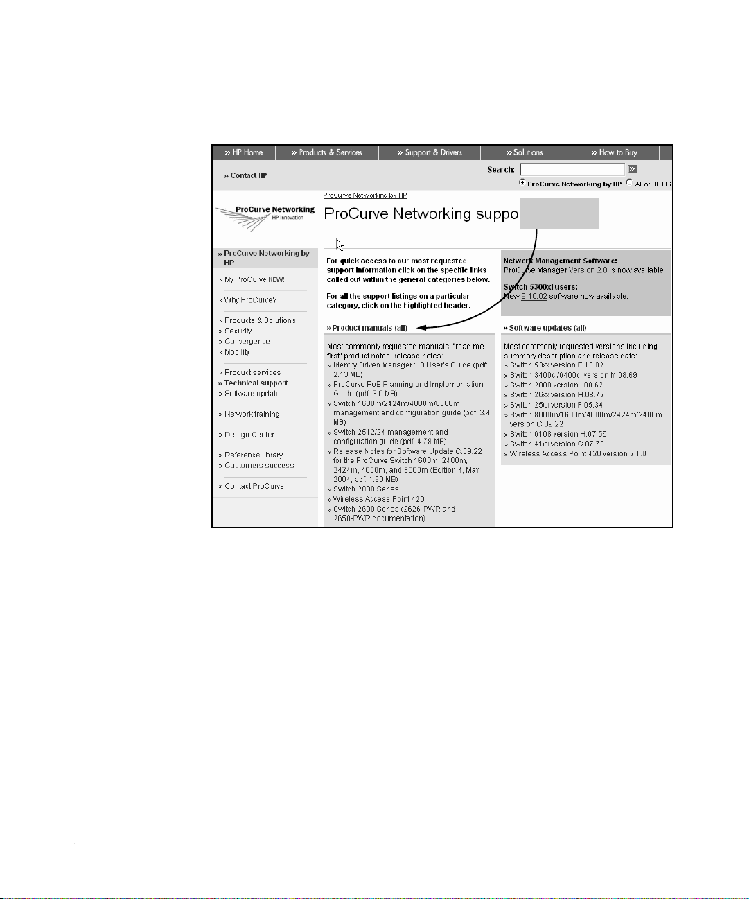
Overview
Using This Guide
5. When the document file opens, click the disk icon in the Acrobat® toolbar
and save a copy of the file.
Click Product
Manuals
1-8
Figure 1-1. The ProCurve Technical Support Web Page
Downloading Software Updates
ProCurve Networking periodically updates the router software to include new
features. You can download software updates and the corresponding release
notes from ProCurve Networking’s Web site as described below.
To download software, complete the following steps:
1. Access the ProCurve Networking Web site at http://www.procurve.com.
2. Click Software updates (in the sidebar). (See Figure 1-2.)
3. Under Latest software, click Secure Router 7000dl Series.
Page 35

Step 2
Overview
Using This Guide
Step 3
Figure 1-2. Downloading Software Updates
Release notes are included with the software updates and provide information
about:
■ new features and how to configure and use them
■ software management, including downloading the new software to the
router
■ software fixes addressed in current and previous releases
1-9
Page 36

Overview
Interface Management Options
Interface Management Options
The ProCurve Secure Router includes two management interfaces: the command line interface (CLI) and the Web browser interface.
CLI
To initially access the CLI, connect the COM port on your workstation to the
console port on the front panel of the router. Use the serial cable (5184-1894)
that was shipped with the ProCurve Secure Router. Then run terminal session
software such as Tera Term or Hyper Terminal on your workstation, setting
the following parameters for the session:
■ Baud Rate = 9600
■ Parity = None
■ Data Bits = 8
■ Stop Bits = 1
■ Flow Control = None
Using the CLI provides you an organized, linear path to help you configure
your router. This guide will focus primarily on configuring the router through
the CLI.
Web Browser Interface
You can also manage the ProCurve Secure Router through the Web browser
interface, which allows you to navigate the router’s (OS) in a GUI environment.
Even if you are a dedicated CLI user, you should try out this easy-to-use Web
browser interface. You will find it especially helpful for more complicated
tasks such as configuring access control policies (ACPs) and virtual private
networks (VPNs). (See Figure 1-3.) In fact, the Web browser interface provides
wizards to help you configure VPNs, the router’s built-in firewall, or QoS
for VoIP.
1-10
Page 37
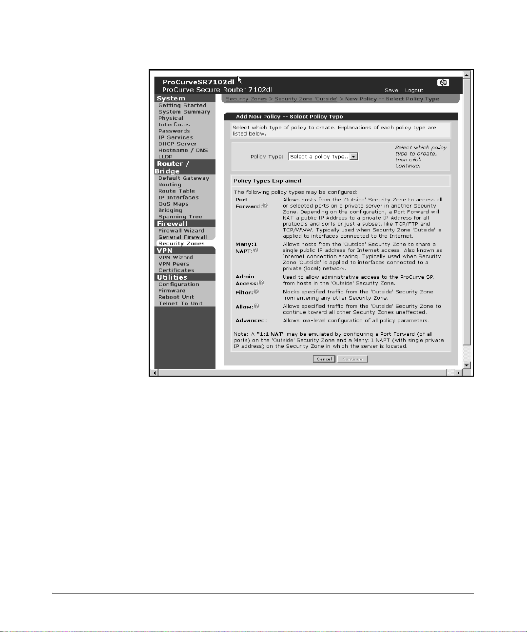
Interface Management Options
Overview
Figure 1-3. Configuring ACPs Using the Web Browser Interface
Accessing the Web Browser Interface
To access the Web browser interface, you must first establish a CLI session
and configure at least one interface through which you can establish an HTTP
session with the router. You must also enable the HTTP server on the router
and configure a password for HTTP access. (For information about enabling
access to the Web browser interface, see “Enabling Access to the Web Browser
Interface” on page 14-4.)
1-11
Page 38

Overview
Interface Management Options
Using the ProCurve Web Browser Interface
The ProCurve Web browser interface is organized into the following sections:
■ System
■ Router/Bridge
■ Firewall
■ VPN
■ Utilities
The System section of the interface contains general router functions. In this
section, you can:
■ configure WAN and LAN connections
■ configure IP services
■ enable the Dynamic Host Configuration Protocol (DHCP) and Domain
■ set the router’s hostname and add entries to the DNS host table
■ configure Link Layer Discovery Protocol (LLDP) settings
You can also click Getting Started to display a help menu, or select System
Summary to display information about the router. Click Physical Interfaces
for a list of interfaces (including status and type) on your router.
Name System (DNS) servers
1-12
The Router/Bridge section allows you to configure the router’s bridging and
routing functions. You can set a default gateway, configure the IP interfaces,
set up quality of service (QoS) maps and routing protocols, and add entries to
the route table. You can also configure the router to act as a bridge and
participate in a spanning tree.
The firewall wizard can be found in the Firewall section. Click Firewall
Wizard to open the wizard in a new window. The wizard guides you through
establishing policies for controlling access to your network. From the Fire-
wall section, you can also enable specific application-level gateways (ALGs)
and set protocol timeouts.
The VPN section includes a wizard that simplifies the process of configuring
an IPSec-compliant VPN. The VPN section eliminates the difficulty of remembering the many commands necessary for configuring a VPN in the CLI. The
VPN section only appears in the Web browser interface if you have installed
an optional IPSec encryption module in the rear panel of your router.
You can perform most of your file maintenance in the Utilities section. Click
Configure to complete tasks such as saving, downloading, uploading, and
deleting files. You can also click Firmware to view information about your
Page 39

Hardware Overview
router’s current OS and upload any necessary upgrades. You can click Reboot
and restart the router, and you can also set up a Telnet session by clicking
Telnet to Unit.
Overview
Note In the CLI, boot and configuration files are referred to as software. In the Web
browser interface, the boot and configuration files are called firmware.
For more information on how to configure your ProCurve Secure Router using
the Web browser interface, see Chapter 14: Using the Web Browser Interface
for Basic Configuration Tasks.
Hardware Overview
This section provides a brief overview of external features, slots, and modules
on the ProCurve Secure Router 7000dl Series. The ProCurve Secure Router
7000dl Series includes two models: the ProCurve Secure Router 7102dl and
the ProCurve Secure Router 7203dl. Both models include two narrow module
slots. The ProCurve Secure Router 7203dl also includes one wide module slot.
ProCurve Secure Router Front Panel
To make accessing the router and connecting it to other devices more convenient, the console interface and all physical link ports are located on the front
panel of the router. The front panel of each router includes two Ethernet
interfaces and two narrow dl option module slots that can house your two
choices from among ten narrow modules. The ProCurve Secure Router 7203dl
also provides a wide module slot to support up to eight additional T1 or E1
lines.
The following sections briefly introduce the features on the front of your
ProCurve Secure Router.
Console Port
The console port, which is a DB-9 DTE male connector, allows you to manage
the ProCurve Secure Router locally. To access the CLI, use the serial cable
(5184-1894) supplied with the router to connect the console port to the COM
port on your laptop or PC. (See Figure 1-4.)
1-13
Page 40
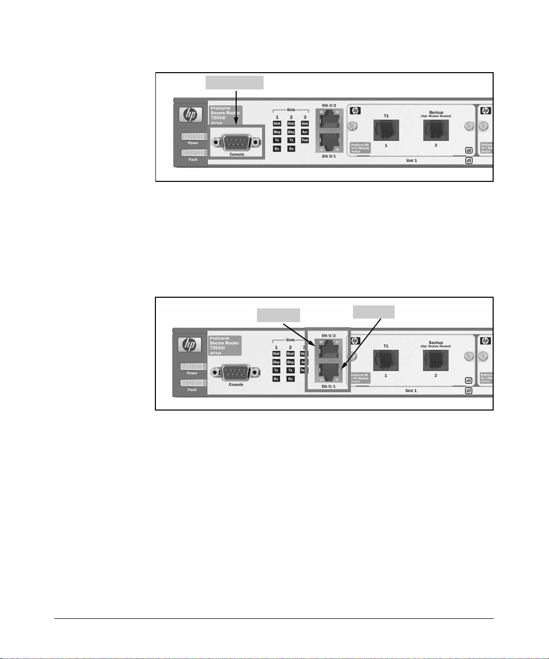
Overview
Hardware Overview
Console Port
Figure 1-4. Connecting to the Console Port
Ethernet Ports
Because the two Ethernet ports are not modular, they are assigned a fixed slot
and port number. For interface notation purposes, these ports are labeled Eth
0/1 and Eth 0/2. (See Figure 1-5.)
Eth 0/2
Eth 0/1
Figure 1-5. Connecting to the Two Ethernet Ports
The Ethernet ports support a 10 Mbps or a 100 Mbps connection. Connect
these ports to your LAN using 10Base-T or 100Base-T cabling with an RJ-45
connector that meets the EIA/TIA-568-A and 568-B standards. For a 10 Mbps
connection, use a Category 3 cable or better. For a 100 Mbps connection, use
a Category 5 cable or better.
Slots
The ProCurve Secu re Router models 7102dl and 7203dl are both equipped with
two narrow slots. (See Figure 1-6.)
1-14
Page 41
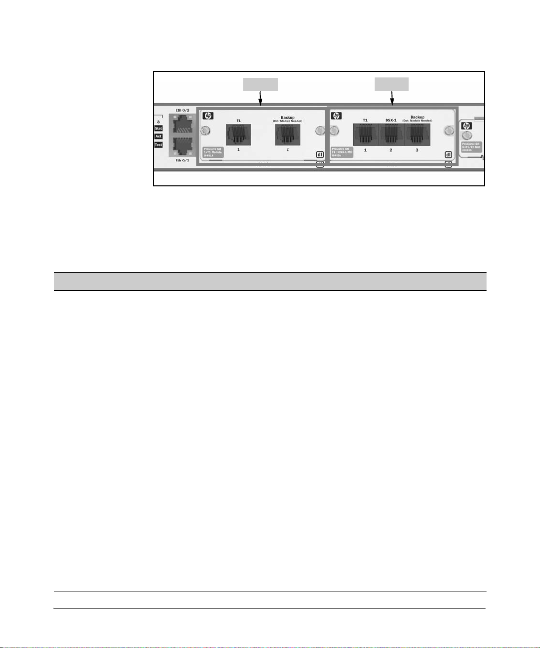
Hardware Overview
Overview
Slot 1
Figure 1-6. Two Narrow Slots
Each slot can house one of the ten narrow modules available for WAN
connections. (See Table 1-1.)
Table 1-1. Narrow Slot Modules
Module Type of Module Explanation
E1 modules:
• one-port module
• two-port module
T1 modules:
• one-port module
• two-port module
E1 module with integrated DSU supports E1-carrier lines when the service provider
T1 module with integrated
CSU/DSU
does not provide an external DSU
supports T1-carrier lines when the service provider
does not provide an external CSU/DSU
Slot 2
E1 + G.703 module E1 for data and analog voice allocates some channels of the E1-carrier line for data
T1 + DSX-1 module T1 for data and analog voice allocates some channels of the T1-carrier line for data
serial module T1- or E1-carrier line that
connects to an external CSU/
DSU using a serial connector
ADSL2+ Annex A module ADSL2+ for most regions of
North America
ADSL2+ Annex B module ADSL2+ for Germany and oth er
areas of the world
ISDN module (two ports) ISDN BRI for voice and data provides cost-efficient, dial-up WAN access
transmission and some channels for voice (through a
PBX)
transmission and some channels for voice (through a
PBX)
supports E1- or T1-carrier lines when the service
provider provides an external CSU/DSU
provides up to 25 Mbps downstream and 1.544 Mbps
upstream; enab les analog voice traffic to be transmitted
at lower frequencies on the local loop
provides up to 25 Mbps downstream and 1.544 Mbps
upstream; enables Integrated Services Digital Network
(ISDN) voice and fax traffic to be transmitted at lower
frequencies on the local loop
1-15
Page 42

Overview
Hardware Overview
Note For information on these or additional modules, please check the ProCurve
Web site at www.procurve.com. Click on Products & Solutions in the left
bar, then click on Secure Router 7000dl series under WAN.
E1 and T1 Modules
E-carrier lines are used in Europe, Asia, Australia, and South America.
T-carrier lines are used in the United States, Canada, and, to some degree,
in Japan.
Note Japan uses J-carrier lines for voice and both T-carrier and E-carrier lines for
data. J-carrier lines are not supported by the ProCurve Secure Router.
The type of module you purchase to support your E1 or T1 WAN connection
depends on how your public carrier implements the Channel Service Unit/
Digital Service Unit (CSU/DSU) that is required for E1- and T1-carrier lines.
The CSU/DSU has two main functions. The DSU accepts traffic from the router
and translates it from the signaling format used on the LAN to the format
necessary for transmission on the WAN. The CSU then generates the signal to
be sent across the WAN.
The public carrier can provide:
■ the CSU/DSU as one complete unit
■ only the CSU
■ neither the CSU nor the DSU
Common practice varies depending on the region in which the public carrier
operates. In Europe, Asia, Australia, or South America, the public carrier will
either provide the CSU/DSU or just the CSU. In North America, the public
carrier will provide the CSU/DSU, or the public carrier will not provide either
the CSU or DSU. (For more information about E1- and T1-carrier lines, see
Chapter 4: Configuring E1 and T1 Interfaces.)
E1 Modules. If you are leasing an E1-carrier line and the public carrier
provides only the CSU, you will need to purchase one of the E1 modules, which
include a built-in DSU. (See Figure 1-7.) You can select:
■ a one-port E1 module, which supports a full E1-carrier line (32 channels
or 2.048 Mbps)
■ a two-port E1 module, which provides 2.048 Mbps on each interface (4.096
Mbps total)
■ an E1 + G.703 module, which enables you to use some channels for data
and some channels for voice
1-16
Page 43
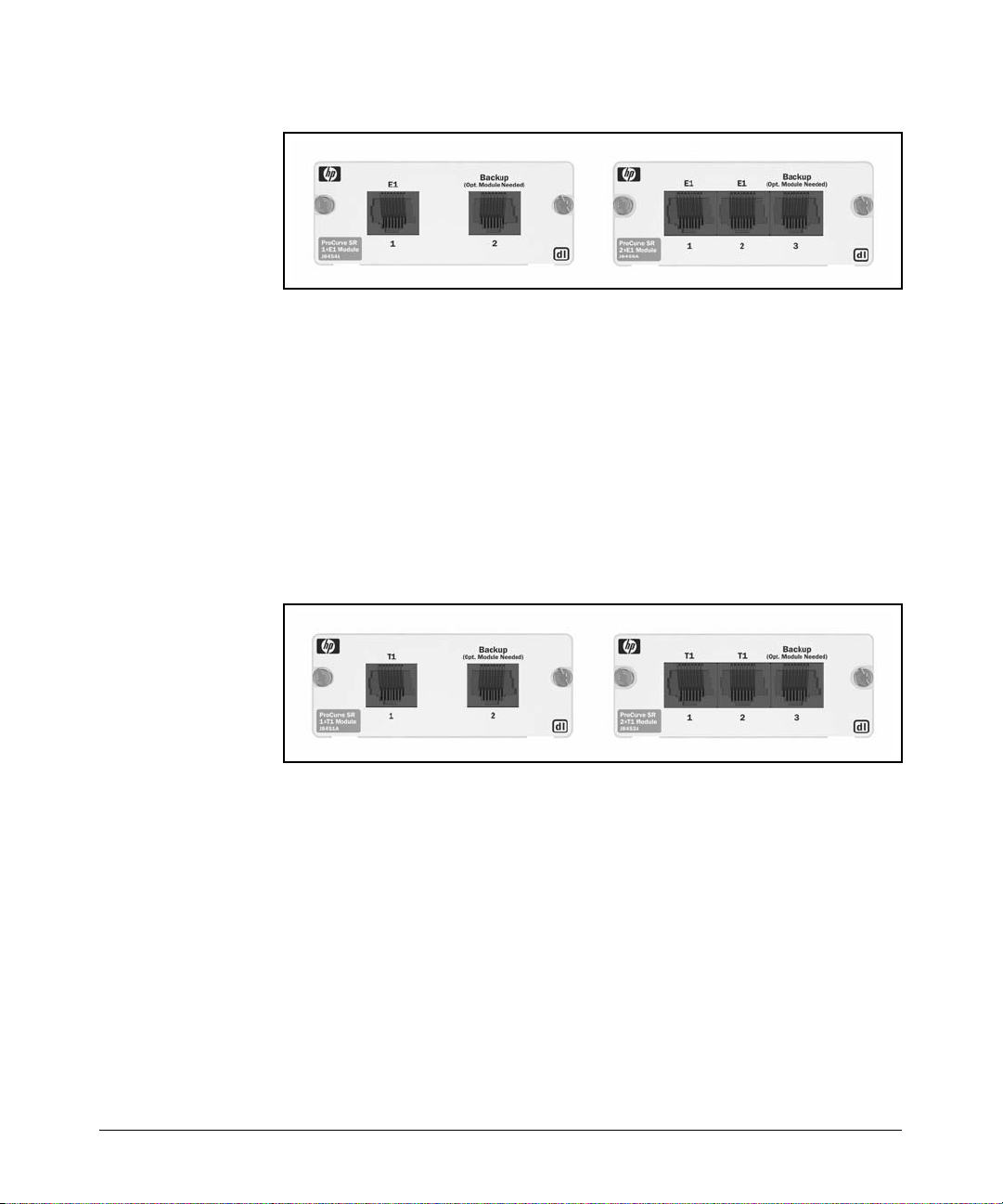
Hardware Overview
Overview
Figure 1-7. E1 Modules
T1 Modules. If you are leasing a T1-carrier line and the public carrier does
not provide a CSU/DSU, you will need to purchase one of the three narrow
slot T1 modules, which include a built-in CSU/DSU. (See Figure 1-8.) Select:
■ a one-port T1 module, which supports a full T1-carrier line (24 channels
or 1.544 Mbps)
■ a two-port T1 module, which provides 1.544 Mbps on each interface (3.088
Mbps total)
■ a T1 + DSX-1 module, which enables you to use some channels for data
and some channels for voice
Figure 1-8. T1 Modules
Serial Module. If you lease an E1- or T1-carrier line and the public carrier
provides an external CSU/DSU, you will need to purchase the serial module.
(See Figure 1-9.)
1-17
Page 44
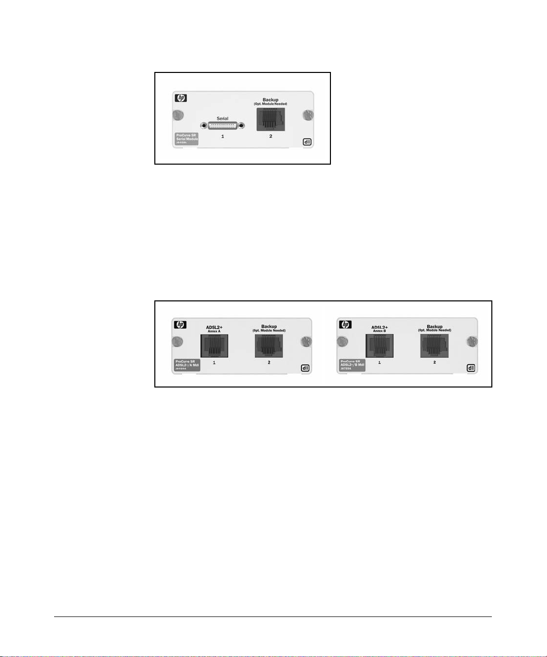
Overview
Hardware Overview
Figure 1-9. Serial Module
ADSL2+ Annex A or Annex B Module. The ADSL2+ modules provide
bandwidth up to 25 Mbps downstream and 1.544 Mbps upstream. Because
ADSL also supports analog voice on the local loop, existing telephone equipment and fax machines can continue to carry traffic on the same line. The
ADSL2+ Annex A module supports analog voice over the Plain Old Telephone
Service (POTS). The ADSL2+ Annex B module supports ISDN voice and fax
traffic. (See figure 1-10.)
1-18
Figure 1-10. ADSL Modules
ISDN Module
The two-port ISDN module provides two Basic Rate Interface (BRI) lines for
dial-up connections. Each ISDN BRI line can deliver a maximum bandwidth
of 128 Kbps. (See Figure 1-11.) The S/T interface module is most often used
outside North America. The U interface module is used in WAN connections
in the United States and Canada.
Page 45
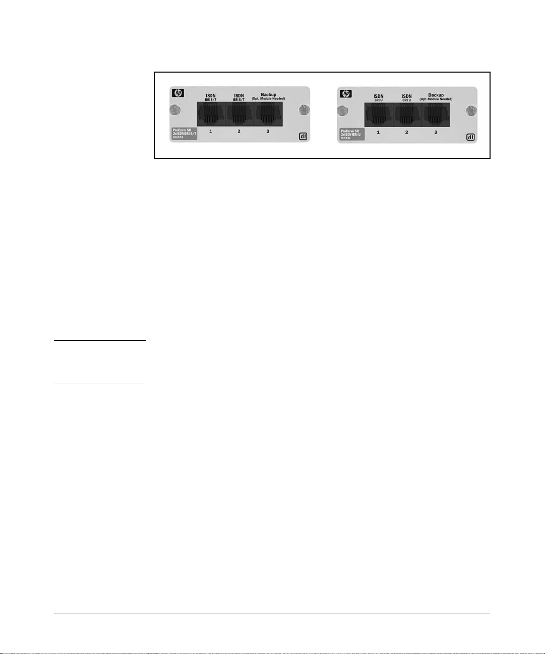
Hardware Overview
Overview
Figure 1-11. ISDN BRI Modules
Backup Modules
A backup connection protects a company’s WAN operations against system
failure. Three types of backup modules are available for the ProCurve Secure
Router:
■ ISDN BRI S/T backup module for use outside of North America—supports
a 64 Kbps backup call or a bonded 128 Kbps call
■ ISDN BRI U backup module for use in the US and Canada—supports a 64
Kbps backup call or a bonded 128 Kbps call
■ VTU V.90 compliant analog modem—provides a connection speed of up
to 56 Kbps
Note Backup ISDN call bonding is currently a ProCurve proprietary technology. If
you bond your BRI backup call, your router can only place the call to another
ProCurve Secure Router.
With the ProCurve Secure Router, it is not necessary to devote an entire
module slot for a backup connection. Each module includes a backup interface port. To activate the backup interface, you must purchase a separate
backup module and install it on top of the module, as shown in Figure 1-12.
1-19
Page 46
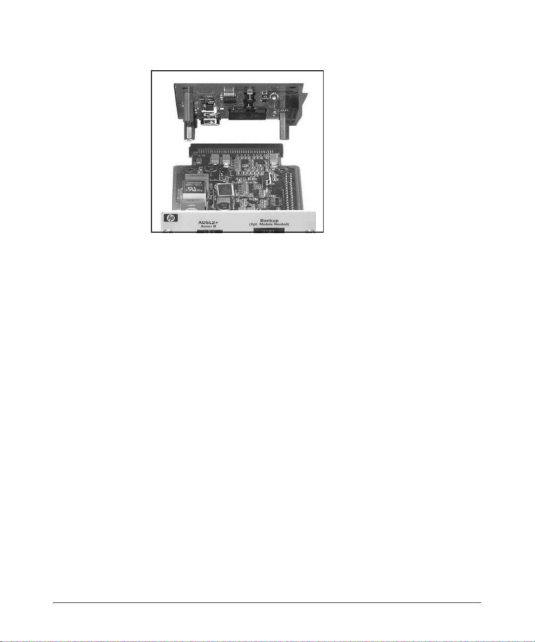
Overview
Hardware Overview
Figure 1-12. Installing a Backup Module on Top of a Narrow Slot Module
Each backup module can be used to back up any WAN connection on the
router, no matter where the backup module is housed.
Wide-Slot Option Modules
The ProCurve Secure Router 7203dl includes a third, wide-module slot.
ProCurve offers an eight-port E1/T1 module and an eight-port serial module.
(See Figure 1-14 and Figure 1-15). This module supports both E1 and T1
formats and can be toggled between the two. The toggle switch is located on
the top of the module. Set the switch to ON for E1 format; set the switch to 1
for T1 format. Figure 1-13 shows the location of the toggle switch on the
module.
1-20
Page 47
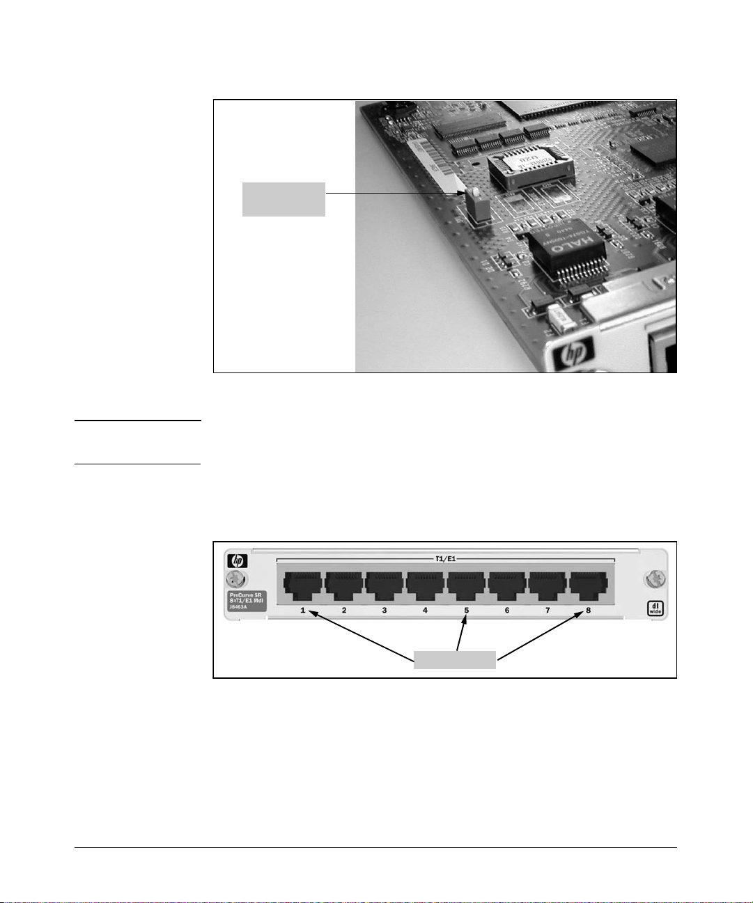
Hardware Overview
E1/T1 Toggle
Switch
Overview
Figure 1-13. E1/T1 Toggle Switch
Note Although the ProCurve Secure Router 7203dl can support up to 12 E1 or T1
lines, the router only supports enough throughput for up to 8 E1 or T1 lines.
You can configure each of the eight ports independently with separate clock
sources, frame formats, and other specifications.
Port Numbers
Figure 1-14. The Eight-port T1/E1 Module
1-21
Page 48
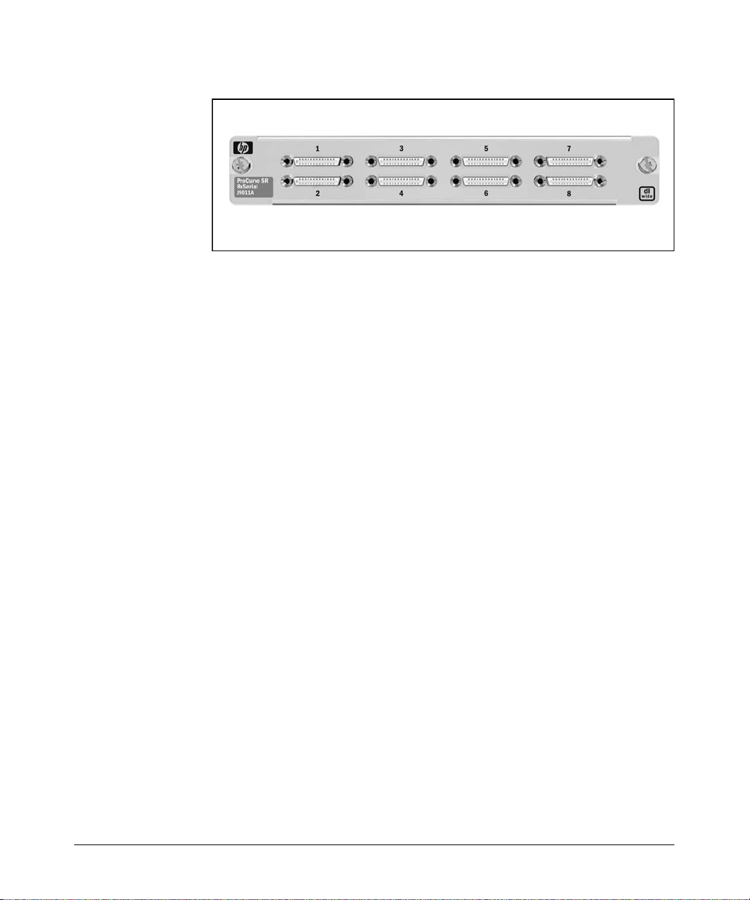
Overview
Hardware Overview
Figure 1-15. The Eight-port T1/E1 Serial Module
Interface Numbering Conventions
When configuring a WAN connection, you will need to specify the slot and
port of the physical interface that is providing the connection. The syntax for
specifying a physical interface is <interface> <slot>/<port>.
Replace <interface> with the name of the interface. For example, for E1
interfaces, you would use e1, and for ADSL interfaces you would use adsl. For
ISDN interfaces, use bri.
Replace <slot> with the slot number in which the module is inserted. The
slots on the router are numbered from left to right. The left narrow slot is slot
1, and the slot to the right is slot 2. If you have a ProCurve Secure Router
7203dl, the wide module is installed in slot 3, the rightmost slot.
Finally, replace <port> with the number of the port on the module. Like the
slots, the ports are numbered from left to right. The port number is printed
below each port on the module. (See Figure 1-14)
For example, if you have a two-port T1 module in slot one, you would
configure the left T1 port by entering:
ProCurve(config)# interface t1 1/1
To configure the other T1 port, you would enter:
ProCurve(config)# interface t1 1/2
As mentioned earlier, the Ethernet interfaces are also labeled in <slot>/
<port> notation as eth 0/1 and eth 0/2.
1-22
Page 49
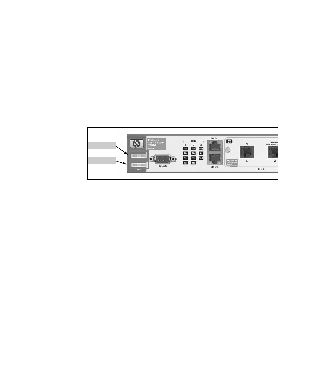
Hardware Overview
Overview
Status LEDs
ProCurve Secure Routers feature LEDs on the front panel to provide information about the condition of the router itself and of the modules you have
installed. This section describes how to interpret these LEDs.
Power LED
The power LED indicates the router’s power status. (See Figure 1-16 for its
location on the front panel.) It displays one of the following:
■ No light—The AC power input is off.
■ Solid green—The power is on.
Power LED
Fault LED
Figure 1-16. Power and Fault LEDs
Fault LED
The fault LED is located directly below the power LED. (See Figure 1-16.) It
flashes orange to indicate any fault condition, including:
■ a cooling fan failure
■ a failure in the option modules
If the power source in the ProCurve Secure Router 7102dl fails, the router
turns off, as do its LEDs. However, the ProCurve Secure Router 7203dl
features a redundant power source (RPS) outlet to provide greater network
stability. When a problem occurs with the primary power source, the fault LED
flashes orange, and the RPS begins to supply power to the ProCurve Secure
Router. Problems with the primary power source include:
■ AC power not being received
■ primary AC/DC power converter failure
When the fault LED is flashing slowly on a ProCurve Secure Router 7203dl,
the RPS is currently in use.
1-23
Page 50
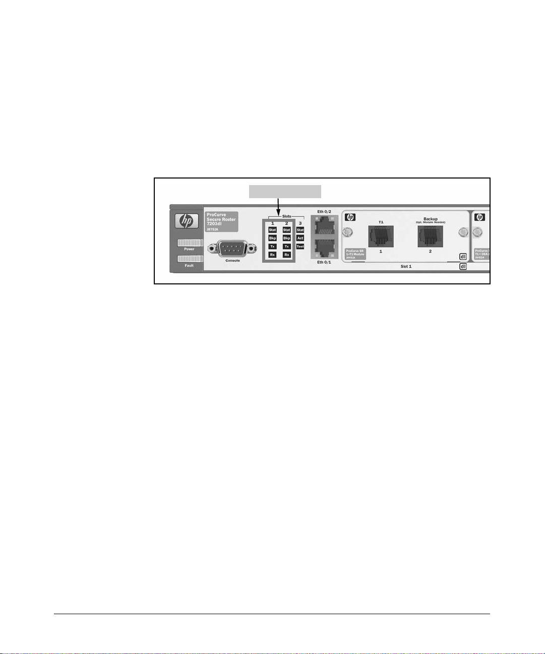
Overview
Hardware Overview
LEDs for Slots 1 and 2
Both the ProCurve Secure Router 7102dl and 7203dl have two columns of
LEDs that report information about the modules installed in the narrow slots.
As you would expect, column 1 reports information about the module in slot
1, and column 2 reports information about the module in slot 2. Each column
contains four LEDs; each LED monitors a different aspect of the module’s
Physical and Data Link Layer connections. (See Figure 1-17.)
Slot 1 and 2 LEDs
Figure 1-17. Two Columns of LEDs Report Information about the Modules in Slots
1 and 2.
Status LEDs
The first LED in each column signals whether or not the module in the
corresponding slot is functional and connected to the network. The status
LED can display one of the following:
■ No light—No module has been installed, or the interface is administra-
tively down. An interface is administratively down until you activate it.
■ Red—A module has been installed, and the corresponding interface has
been activated, but no valid physical connection has been established.
Red LEDs may also indicate other problems with the interface, such as:
• a self-test failure
• an active WAN alarm condition
■ Green—A module has been installed and activated, and the physical
connection is up and operational.
■ Yello w —An interface on the module is being tested.
1-24
Page 51

Hardware Overview
Overview
Backup LEDs
The second LED in each column reports the status of the backup module, if a
backup module is installed. The LED in the first column corresponds to the
backup module in slot one, and the LED in the second column corresponds
to the module in slot two. The status LEDs for backup modules can display
one of the following:
■ No light—A backup module has not been installed and activated.
■ Red—The backup module has been activated and configured, but a valid
physical connection has not been made. A red LED may also indicate that
the backup interface has received a WAN alarm or has failed a self-test.
■ Solid green—The module is ready to be used if a connection that it backs
up should fail. For ISDN BRI backup modules, a solid green light further
indicates that the module has completed negotiation with the switch.
■ Yello w —A self-test is in process.
■ Flashing green—The backup link is currently active.
Tx and Rx LEDs
The Tx and Rx LEDs signal WAN activity across the corresponding interface’s
link. The third (Tx) LED in each column signals that the interface is transmitting data, and the fourth (Rx) LED indicates that the interface is receiving data.
Tx and Rx LEDs signal the following:
■ Off—The link is inactive.
■ Green—Data is being transferred across the WAN or backup interface.
Slot 3 LEDs
The ProCurve Secure Router 7203dl includes a third column of LEDs that
represent the wide module. Unlike the other columns of LEDs, this column
includes only three LEDs. (See Figure 1-18.)
1-25
Page 52
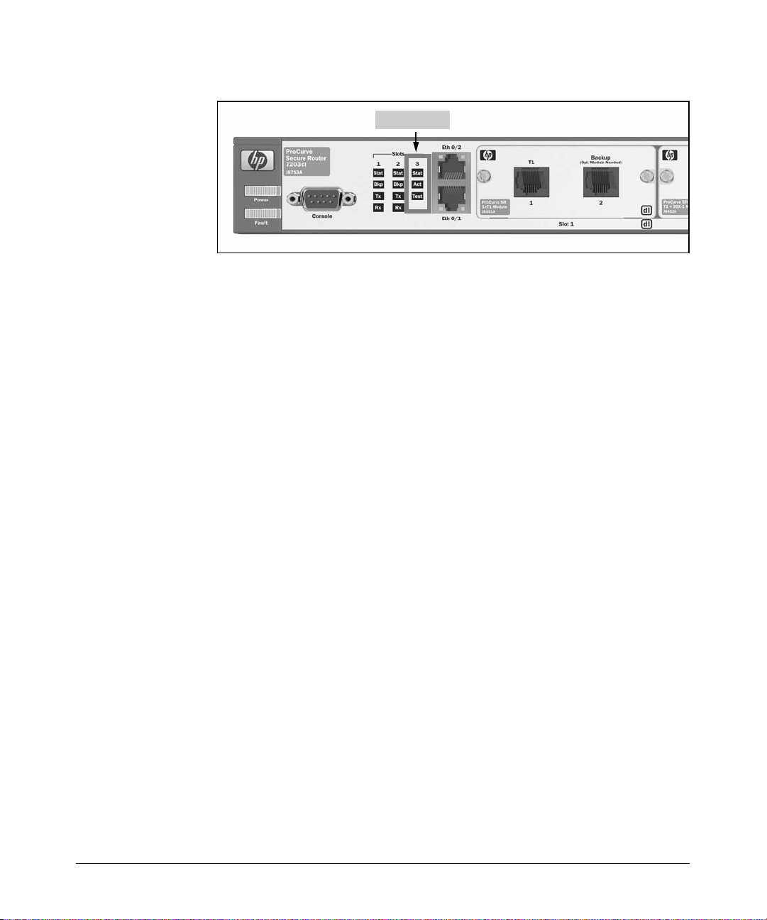
Overview
Hardware Overview
Slot 3 LEDs
Figure 1-18. On the ProCurve Secure Router 7203dl, the Third Column LEDs Report
on the Wide Module.
Status LED
The first LED reports on the status of the wide module, indicating whether the
wide module is installed and functional.
■ No light—The module has not been installed or none of the interface
ports have been activated.
■ Green—The module has been recognized and at least one interface is up.
■ Red—There is an active alarm condition on one of the interfaces.
1-26
Activity LED
The second LED reports activity across the WAN links established through
the wide module. The LED flashes green to signal activity.
Test LE D
The third LED glows solid yellow if one of the interfaces on the module is in
test mode.
Ethernet and Activity LEDs
The Ethernet interfaces also have LEDs that report on their status and activity.
(See Figure 1-19.)
Page 53
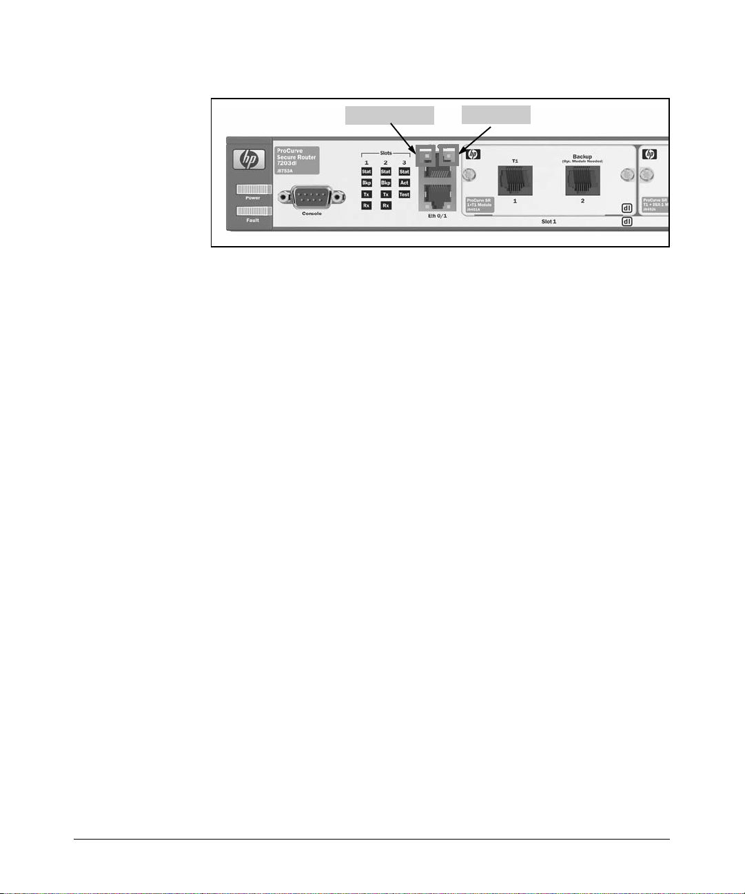
Hardware Overview
Overview
Activity LED
Link LED
Figure 1-19. LEDs for Ethernet Interfaces
Activity LEDs
Activity LEDs signal data transfer between the LAN and the router.
■ No light—The Ethernet connection is inactive.
■ Flashing yellow—The link is currently transmitting or receiving data.
Link LEDs
Link LEDs signal whether or not the router recognizes a valid connection to
a LAN.
■ No light—The Ethernet interface is down.
■ Green—The Ethernet interface is up.
Rear Panel
The rear panel of the ProCurve Secure Router includes a slot for an optional
IPSec VPN module and a slot for a compact flash card. The ProCurve Secure
Router 7203dl also includes an additional feature: an outlet for a Redundant
Power Source.
Optional IPSec VPN Module
If your company wants to establish virtual private networks (VPNs) over the
Internet, you can install the IPSec VPN module in the slot provided on the
ProCurve Secure Router’s rear panel. (See Figure 1-20.) The router can then
establish a VPN with another router or with a VPN client that is installed on a
user’s workstation. Remote sites and individual users can then connect to your
company’s network through private Internet connections.
1-27
Page 54
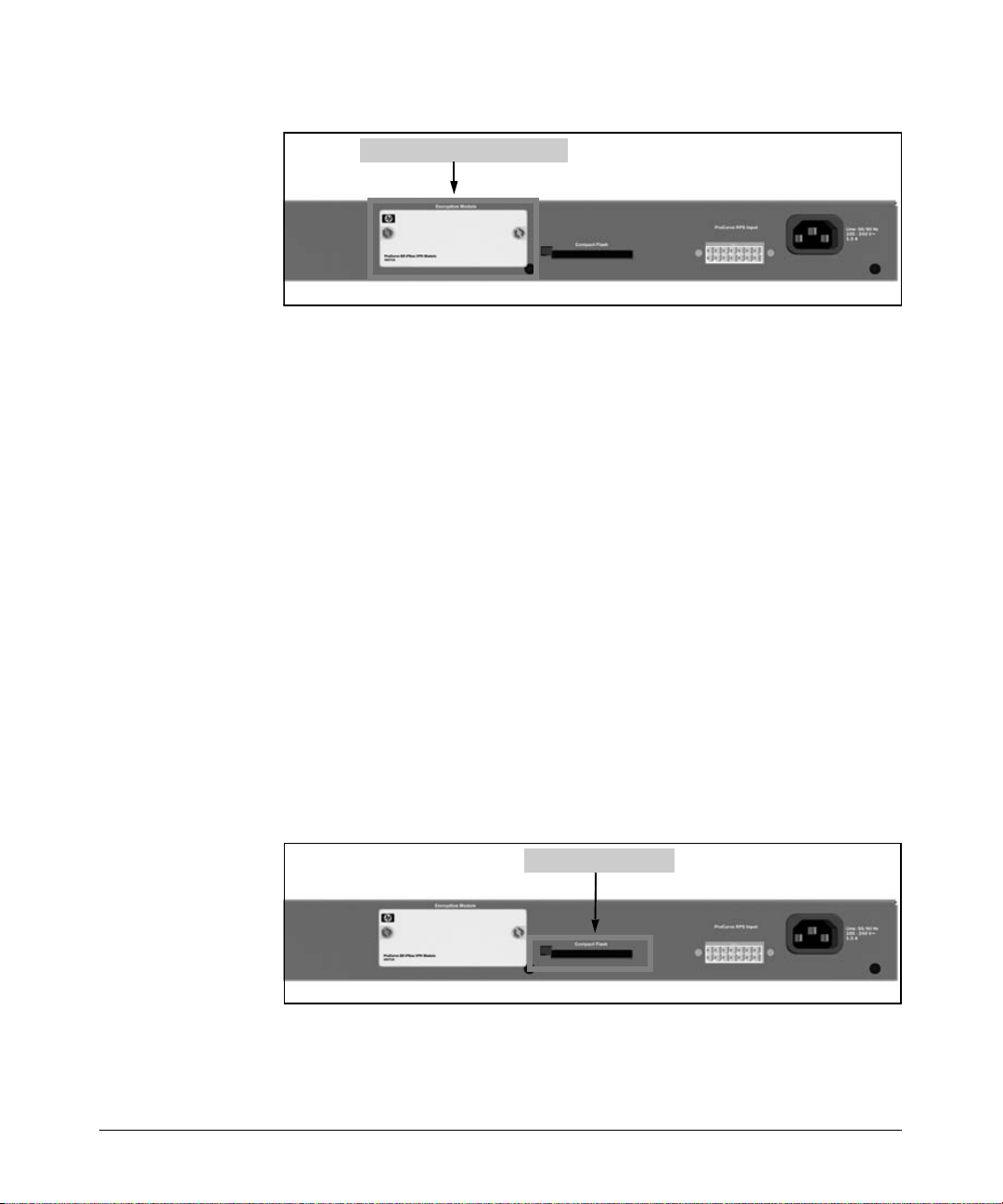
Overview
Hardware Overview
Slot for the IPSec VPN module
Figure 1-20. IPSec VPN Module
To protect your network from security breaches through the Internet, the
ProCurve Secure Router establishes secure VPN tunnels using the industrystandard IP Security (IPSec) protocol. The IPSec VPN module enables the
software that supports the IPSec protocols and relieves the CPU of the
overhead associated with processing the encryption algorithms.
When the IPSec VPN module is installed, the ProCurve Secure Router 7102dl
supports up to 500 VPN tunnels; the ProCurve Secure Router 7203dl supports
up to 1000 tunnels.
Compact Flash Card
The compact flash slot on the ProCurve Secure Router’s back panel supports
most standard compact flash cards. (See Figure 1-21.) To protect your
ProCurve Secure Router against system failure, you can store the Secure
Router OS software and your configuration file on a compact flash card. In
fact, the ProCurve Secure Router provides additional features that automatically use compact flash to safeguard the Secure Router OS and your configurations. These features are described in “Bootup Process” on page 1-30 and
“AutoSynch™ Technology” on page 1-34.
Compact flash slot
Figure 1-21. Compact Flash Slot on Rear Panel of the ProCurve Secure Router
1-28
Page 55
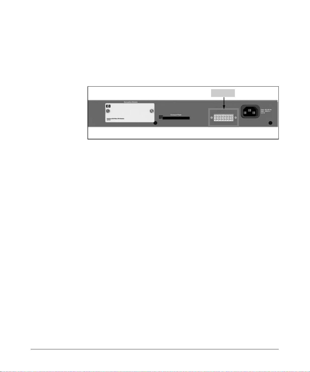
Hardware Overview
Overview
Redundant Power Source
The RPS outlet on the back panel of the ProCurve Secure Router 7203dl
provides increased router reliability for mission-critical applications. (See
Figure 1-22.) The RPS slot can be used with the ProCurve 600 Redundant
External Power Supply.
RPS slot
Figure 1-22. RPS Outlet on the ProCurve Secure Router 7203dl
Memory
Both the ProCurve Secure Router 7102dl and 7203dl have 32 MB of internal
flash memory. The flash memory provides nonvolatile random access memory
(NVRAM); in other words, the router retains what is stored in the internal flash
even when the router is powered down.
Because internal flash memory is relatively limited, SROS software is stored
in compressed form. The SROS software file is approximately 6 MB. The
number of configuration files that can be saved in internal flash is limited only
by the amount of available memory. Because configuration files tend to be
small, you will be able to save multiple configuration files in internal flash.
In addition to internal flash, the ProCurve Secure Router 7102dl has 128 MB
of random access memory (RAM), which holds the running configuration. All
information in RAM is lost when the router is powered off. The ProCurve
Secure Router 7203dl has 256 MB of RAM.
1-29
Page 56

Overview
Software Overview
Software Overview
To manage your ProCurve Secure Router, you must understand basic router
operations, including how the router uses:
■ Secure Router OS (SROS) boot code
■ SROS software
■ the startup-config
■ the running-config
Further, you must understand how the Secure Router OS is organized so that
you can properly configure the router and enable safeguards to protect the
router from unauthorized access.
This section describes software operations such as the boot process, the
process of saving configurations, the OS hierarchy, and the bootstrap mode.
Bootup Process
Concurrent with the release of J02_02A.biz software in July 2005, ProCurve
Networking changed the boot process for the ProCurve Secure Router. By
default, the ProCurve Secure Router now boots from compact flash. If a
compact flash card is not inserted into the compact flash slot or if the card
does not contain the required Secure Router OS file, the router will boot from
internal flash. Previously, the ProCurve Secure Router booted only from
internal flash.
This change has been made in routers that shipped after July 2005; these
routers have the following serial numbers:
■ ProCurve Secure Router 7102dl (J8752A) US525TRAP4 or later
■ ProCurve Secure Router 7203dl (J8753A) US522TS252 or later
Note If you purchased a ProCurve Secure Router before this change was made, you
can enable the new boot process by upgrading to J02_02A.biz or later and
making a small configuration change. For information about this configuration change, see Appendix A: Configuring the Router to Boot from Compact
Flash.
1-30
Page 57

Software Overview
Overview
The boot process begins when you power up the ProCurve Secure Router or
manually reload it. It proceeds as follows:
1. The router first loads the SROS boot software (which has been set through
the copy <source> <filename> boot command).
2. The router then searches compact flash for the SROS.BIZ file, which
contains the Secure Router OS software.
• If the router finds the SROS.BIZ file in compact flash, it will load this
SROS software and begin step 3.
• If a compact flash card is not installed or the SROS.BIZ file on the
card is missing or corrupted, the router searches for this file in
internal flash. If the router finds the SROS.BIZ file in internal flash, it
loads this SROS software and begins step 3.
• If the router does not find a valid SROS.BIZ file in either compact flash
or internal flash, the router boots up in bootstrap mode (as described
in “Bootstrap Mode Context” on page 1-66).
3. After the router finds a valid SROS.BIZ file (either in compact flash or
internal flash), it checks compact flash for the startup-config file, which
contains the saved configurations for the router.
• If the router finds the startup-config file in compact flash, it loads this
file.
• If the router does not find the startup-config in compact flash, it
searches for the startup-config file in internal flash. If it finds the
startup-config in flash, it loads this configuration.
• If the router does not find the startup-config file in either compact
flash or internal flash, the router boots in basic mode using the factory
default configuration settings.
1-31
Page 58
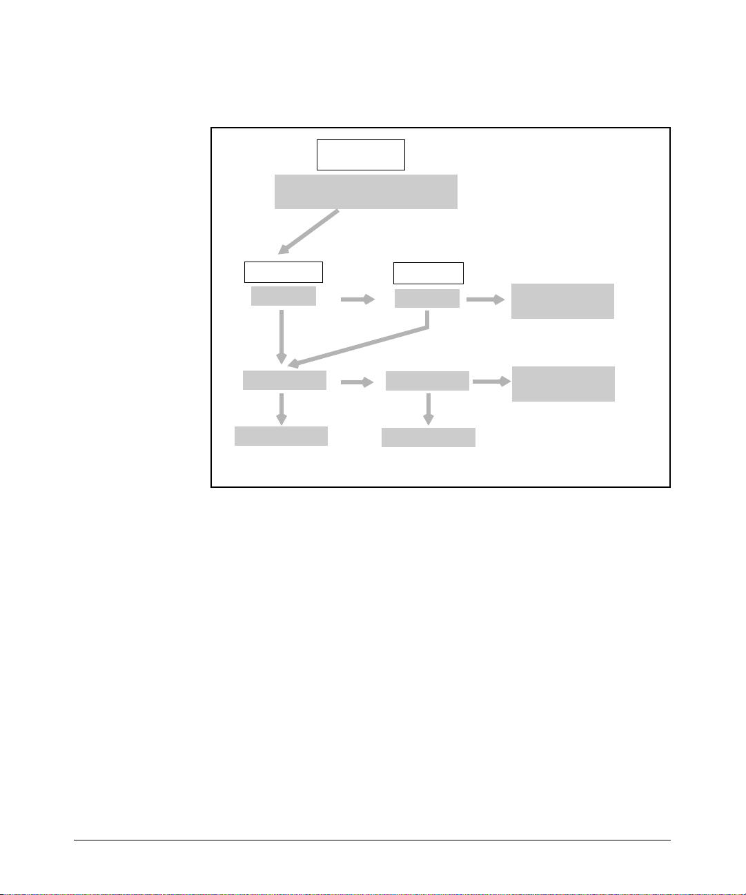
Overview
Software Overview
Figure 1-23 summarizes the boot process.
ProCurve Secure
Router
Router loads the boot software
(J0X_0X-boot.biz) from internal flash
Checks compact flash
(cflash) for SROS.BIZ
compact flash
No
SROS.BIZ
Ye s
No
startup-config
boot-basic mode
internal flash
SROS.BIZ
Ye s
startup-config
Ye sYe s
boot-basic mode
No
No
Router boots in
bootstrap mode
Router boots using
default settings
Figure 1-23. Booting the ProCurve Secure Router
Advantages of Booting From Compact Flash
Booting from compact flash simplifies router setup. You can use a compact
flash card to preconfigure a router and simply send the card to a remote site.
Any person at the remote side can insert the compact flash card into the router,
connect the cables that will enable the LAN and WAN connections, and power
up the router. The ProCurve Secure Router will boot with the SROS.BIZ file
and startup-config on compact flash, and the router will be immediately
operational.
1-32
To check the configuration by remote, you can simply establish a Telnet or
Secure Shell (SSH) session with the router or use the Web browser interface.
Page 59

Software Overview
Overview
Setting Up a Compact Flash Card From Which to Boot the Router
Newly shipped ProCurve Secure routers have an internal flash that contains
two SROS software files:
■ J0X_0X.biz
■ SROS.BIZ
The SROS.BIZ and J0X_0X.biz files are identical. The J0X_0X.biz file reflects
the version number of the software, such as J04_01.biz. This file has then been
resaved as SROS.BIZ.
Internal flash also contains the startup-config file. At this point, the startupconfig file contains the default configuration for the router. Once you have
configured your router and saved the configurations, the new startup-config
file will allow the router to boot up with the configurations you have made.
To set up a new compact flash card so that the router can boot from it, insert
the card into the slot provided on the back panel of the router and copy the
following files from flash memory to compact flash:
■ J0X_0X.biz
■ SROS.BIZ
■ startup-config
After you copy the files to a compact flash card, take the card to any ProCurve
Secure Router. Unless its boot process has been altered, the router will
automatically boot from the software and startup-config file stored on
the card.
When ProCurve Networking releases new software, part of the update process
will include renaming the new file as SROS.BIZ and copying the new file to
compact flash and to internal flash. When you need to know the version of
software the router is using, the show version command will display the exact
version. (This and other show commands are described later in this chapter.)
Saving Configuration Changes
When the ProCurve Secure Router loads the startup-config, it executes it line
by line as the running-config. As you make configuration changes, these
changes are held in RAM. Because RAM is cleared every time the router is
powered down, you must save any changes that you want to keep to the
startup-config file.
1-33
Page 60

Overview
Software Overview
When the command is entered, the ProCurve Secure Router first tries to save
these changes to a startup-config file on compact flash. If no compact flash
card is inserted into the slot on the back panel, the router saves the changes
to the startup-config file that is stored in internal flash. If no startup-config file
exists on either the compact flash or internal flash memories, the router
creates the file and saves the configuration to it.
AutoSynch™ Technology
The AutoSynch feature was first released as a free update in the J03_01.biz
software. This feature ensures that the SROS software (SROS.BIZ) and the
startup-config file stored on compact flash are identical to those stored on
internal flash. AutoSynch technology affects only the SROS.BIZ and startupconfig files; any other files that you intend to keep on the compact flash drive
will need to be manually copied from your router’s internal flash to the
compact flash card.
When you save your configurations, the ProCurve Secure Router saves the
running-config to the startup-config stored on the compact flash. If the auto-
synch command is enabled, when you save your current configuration to the
startup-config, the file is saved to both compact flash and internal flash at the
same time.
1-34
AutoSynch technology ensures that you always have a backup copy of your
configuration file and the SROS software you are using. If a hardware failure
should occur, you simply contact ProCurve Networking to get a new part or
even a new unit (if that is required). Then you replace the part, insert the
compact flash card, and power up the router. The router automatically loads
the SROS software and the startup-config from the compact flash card.
Likewise, if the SROS software or the configuration file becomes corrupted,
you have up-to-date backup copies, so downtime is confined to the time it
takes to load these copies. This is especially helpful if the SROS software you
are using is no longer available on the ProCurve Networking Web site (because
subsequent versions have been released).
Secure Router OS Hierarchy
The ProCurve Secure Router OS is organized into two security modes and
then further organized into configuration modes. Each of these modes allows
you to access and configure a separate aspect of your router’s operation. This
OS hierarchy creates levels of security by limiting certain functions to
authorized users.
Page 61
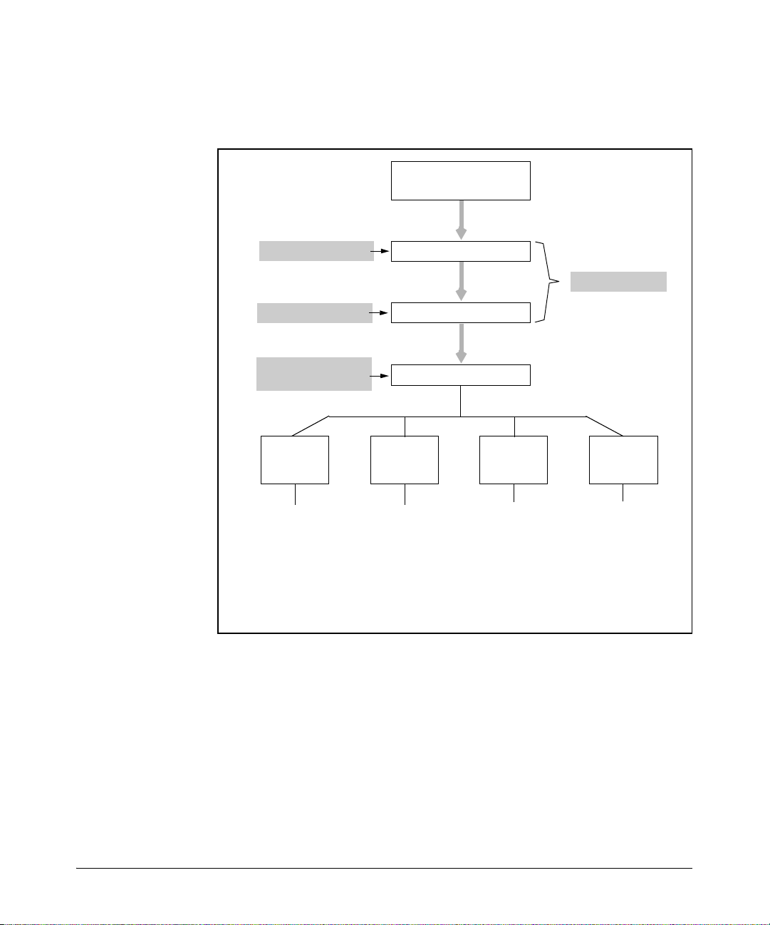
Software Overview
Overview
This section introduces the different mode contexts and describes the types
of commands you can enter in each one. (See Figure 1-24.)
Session now available
Return to get started
Press
Return
Basic mode context
Enable mode context
Global configuration
mode context
Interface
configuration
context
ADSL Loopback
ATM Modem
BRI PPP
Demand Serial
E1 SHDSL
Ethernet T1
Frame Relay Tunnel
HDLC
ProCurve>
ProCurve#
ProCurve(config)#
Line
configuration
context
Console
SSH
Tel n et
enable
configure terminal
Router
configuration
context
BGP
OSPF
RIP
PIM-Sparse
Security modes
Other
configuration
contexts
Crypto IKE policy
Crypto map
IP access-list
IP policy-class
ISDN-group
Figure 1-24. Security and Configuration Modes in the Secure Router OS
To protect your WAN against unauthorized access, the ProCurve Secure
Router has two security modes:
■ basic mode
■ enable mode
1-35
Page 62

Overview
Software Overview
Basic Mode
The basic mode allows restricted access to the router, providing only a limited
number of commands. From this mode, you can view basic system information, verify some processes, and enter traceroute and ping commands. You
do not have access to any of the options that allow you to configure the router.
When you first access the Secure Router OS through the CLI and press
the router is in the basic mode context. To verify your location in the CLI,
check the prompt. In the basic mode context, the prompt is the
shown below:
ProCurve>
From the basic mode context, you can access the enable mode by entering:
ProCurve> enable
> symbol, as
Enter,
Enable Mode
The enable mode is sometimes called the privileged mode because it allows
you to access all management and configuration commands. You can use this
command to view detailed information about how your router is functioning,
perform system management tasks, and gain access to all configuration modes
on the router. From the enable mode, you can save, mode, and delete the
startup-config and running-config files and use the show and debug commands.
Although you cannot actually configure the ProCurve Secure Router from the
enable mode, you can access the global configuration mode from this mode,
and from there, you can access any configuration mode and configure any
aspect of the router. For additional security, you can—and should—password
protect this more-secure OS level.
1-36
In the enable mode context, the prompt is followed by the # symbol, as shown
below:
ProCurve#
From the enable mode context, you can access the global configuration mode
context by entering:
ProCurve# configure terminal
Page 63

Software Overview
Overview
Global Configuration Mode
From the global configuration mode, you can make configuration changes that
apply to the entire router and all interfaces. You can configure the system’s
global parameters, such as the hostname, passwords, and banners. You can
also set parameters for IP services such as DHCP and DNS. You can enable
the built-in firewall and configure global options for that firewall. You can also
configure passwords to protect the enable mode and SSH, FTP, and HTTP
access.
From the global configuration mode context, you can also access other
configuration mode contexts to configure specific router interfaces and functions, such as routing protocols. There are four main types of contexts:
■ interface
■ router
■ line
■ other
Interface. The interface configuration mode contexts enable you to configure the LAN and the WAN connections to your router. To configure an
interface, enter the following command from the global configuration mode
context:
Syntax: interface <interface> [<slot>/<port> | <interface number>]
Replace <interface> with the type of physical interface such as e1, t1, serial,
bri (for ISDN interfaces), adsl, or modem (for analog backup interfaces). You
can also replace <interface> with a logical interface such as ppp, frame-
relay, loopback, or tunnel. For physical interfaces, replace <slot>/<port>
with the slot and port location of the connection, and for logical interfaces,
replace <interface number> with the interface number.
For example, if your router has a T1 module in slot one, you would type
interface t1 1/1 to configure this interface. The CLI prompt will change to
show that you are in the T1 1/1 interface configuration mode context:
ProCurve(config)# interface t1 1/1
ProCurve(config-t1 1/1)#
For another example, if you want to configure a PPP connection to an ISP, you
would enter interface ppp 1 to create and configure a PPP logical interface.
1-37
Page 64

Overview
Software Overview
Router. You can configure dynamic routing protocols from the router configuration mode contexts. There are four router configuration modes: BGP,
RIP, PIM-Sparse, and OSPF. To configure these protocols, move to the global
configuration mode context and use this command:
Syntax: router [bgp | ospf | pim-sparse | rip]
For example, to configure RIP, enter:
ProCurve(config)# router rip
ProCurve(config-rip)#
When configuring BGP, you must also designate an AS number, which can be
between 1 and 65535, in the command line. (Your ISP will provide this
number.)
Syntax: router bgp <AS number>
For example, enter:
ProCurve(config)# router bgp 1
ProCurve(config-bgp)#
Line. Your router has three data lines that allow you to access the ProCurve
Secure Router’s OS: console, SSH, and Telnet. You can configure options for
line sessions by accessing the line configuration mode context.
Syntax: line [console 0 | ssh <0-4> | telnet <0-4>]
For example, you might enter:
ProCurve(config)# line ssh 2
For more information on configuring secure access to the router using these
lines, see Chapter 2: Controlling Management Access to the ProCurve Secure
Router.
Other. You can access other configuration mode contexts from the global
configuration mode context, such as those from which you configure ACLs,
access control policies (ACPs), QoS maps, and crypto maps. You can enter
these configuration contexts from the global configuration mode context or
from individual interface configuration mode contexts.
1-38
Page 65

Software Overview
Overview
Commands Available in the Basic, Enable, or Global Configuration Mode Contexts
The ProCurve Secure Router OS permits you to use certain commands only
in specific modes. When you are managing the ProCurve Secure Router and
you try to use a command that is not supported from the current mode context,
you will receive an error message.
To help you become familiar with the Secure Router OS, the following sections
introduce the types of commands that are available in the three main modes:
basic, enable, and global configuration.
Basic Mode Commands
The basic mode commands include those discussed in the following sections.
Clear
These commands reset router operations or statistical records. Table 1-2
shows the clear commands available in basic mode context.
Table 1-2. Basic Mode Context clear Commands
Option Result
clear counters [<interface>] clears interface counters, such as the
number of packets transmitted and
received or errors detected
clear event-history clears the event history log
clear host [<hostname> | *] deletes host table entries
clear sip [location | user-registration] clears local SIP information
clear user [console | ssh | telnet] detaches a user from a particular line
Enable
To begin managing the router in the enable mode context, enter:
Syntax: enable
1-39
Page 66

Overview
Software Overview
Logout
Exit the current CLI session and return to the login screen.
Syntax: logout
Ping
Send an ICMP echo to a specified destination. To send a default ping of 5
echoes, enter:
Syntax: ping [<A.B.C.D > | <domain name>]
When you begin sending ICMP echoes, the router displays a legend to describe
the types of responses the router receives. For example, Figure 1-25 shows a
successful ping:
ProCurve> ping 1.1.1.1
Legend: ‘!’ = Success, ‘?’ = Unknown host, ‘$’ = Invalid host address
‘*’ = Request timed out, ‘–’ = Destination host unreachable
‘x’ = TTL expired in transit
!!!!!
Success rate is 100 percent (5/5), round trip min/avg/max = 3/3.0/3 ms
1-40
Figure 1-25. Sending a Ping
Typing ping and pressing
Enter without a destination address will allow you to
set extended options for the ICMP echo. Extended options include the number
of pings to be sent, the size of the datagram to be sent, and the timeout value.
The CLI displays default settings in brackets; press
Enter to accept the defaults.
For example:
ProCurve> ping
Target IP address?
Repeat count [5]:
Datagram size [100]:
Timeout in seconds [2]:
Extended commands? [n]
Pressing
y for the Extended commands? option allows you to set the source
address and data pattern. You can also specify that the ping sweep a range of
datagram sizes.
Page 67

Software Overview
Overview
If you enter y for the verbose option in the extended commands, the output
reports the result of each ping with a description of the datagram size and the
echo’s round-trip time. For example:
Reply from 1.1.1.1: bytes = 100 time = 4 ms
If you need to halt a ping operation, press
Ctrl+C.
Note Ping commands are available in all areas of the Secure Router OS.
Show
View information about, or the current status of, an interface or feature. Table
1-3 is a list of show commands available in the router’s basic mode context.
For a more comprehensive list of show commands, see “Show” on page 1-51.
Table 1-3. Basic Mode Context show Commands
Option Result
show arp [realtime] shows the ARP table, which includes interfaces’ IP and
show autosynch-status reports whether the SROS.BIZ and startup-config in
show clock displays clock information such as the time, date, and time
show demand shows demand routing parameters and statistics
show dynamic-dns shows the dynamic DNS hostname and registered IP
MAC addresses
internal flash and compact flash are synchronized
source
address
show event-history displays the events log
show frame-relay [fragment | lmi | multilink | pvc] gives information on Frame Relay fragmentation, LMI
show interfaces [<interface ID> {performance-statistics |
realtime}]
show ip access-list [<name>] displays configured ACLs and the number of packets the
show ip interfaces [demand | ethernet | frame-relay | hdlc |
loopback | ppp | tunnel]
status polls, permanent virtual connections (PVCs), and
multilinks
shows status reports for router interfaces; you can also
specify a particular interface
router has matched to each entry
lists interfaces with their assigned IP addresses and
network masks, the MTU for each interface, and whether
fast caching is enabled on the interface
1-41
Page 68

Overview
Software Overview
Option Result
show isdn-group [<interface number>] lists the ISDN group configurations and member
show lldp [<cr> | device <name> | interface <interface ID> |
<neighbors>]
show memory heap [realtime] displays statistics for the router memory, including how
show modules gives information on the router’s modules, including the
show processes cpu shows the process statistics, including the load percent
show snmp displays the SNMP information and packets received
show sntp shows SNTP information
show thresholds displays the thresholds that have been exceeded on each
show version displays the router system software and hardware
interfaces
displays LLDP settings and information, including
information on specific neighbors
much has been used and how much is available
type of module in each slot and the number of ports in each
module
for each process
E1 or T1 interface
versions
Teln et
Open a Telnet session. (You enable and set the parameters for Telnet sessions
from the Telnet line configuration mode context.)
1-42
Syntax: telnet <A.B.C.D>
For information on how to set up a Telnet session, see Chapter 2: Controlling
Management Access to the ProCurve Secure Router.
Traceroute
Ping an IP address and display the hops that the packet takes en route to the
destination.
Syntax: traceroute <A.B.C.D>
The router will display a route to a destination up to 30 hops away. You can
end the traceroute process at any time by pressing
Ctrl+C.
Page 69

Software Overview
Similar to the ping command, you can set extended options for tracing a route
by entering traceroute and pressing
address. Options include the source address at which the trace begins and the
maximum number of hops.
The traceroute command is also available from the enable mode context.
Enter without specifying the destination
Overview
Term in al
Set the maximum number of lines to display on the screen during a terminal
session.
Syntax: terminal length <0-480>
If a readout includes more lines than the configured terminal length amount,
the display stops at the length limit and displays --MORE-- at the bottom.
To continue the display after the --MORE--, press
next line of the readout, press
the display, press a key.
Enter. To return to the router prompt and end
Spacebar. To only display the
Wall
Broadcast a message through the console port.
Syntax: wall <message>
Enable Mode Commands
To enter the enable mode context, enter enable from the basic mode context.
The following sections briefly describe some of the enable mode commands
and their functions.
Important! ProCurve strongly recommends that you set an enable password to prevent
unauthorized access to the router. If the enable mode context is not password
protected, anyone with console access to the router will be able to change the
configurations and compromise network security. See “Restricting Access to
the Enable Mode Context” on page 2-4 for more information on how to
configure an enable mode password.
1-43
Page 70

Overview
Software Overview
Clear
The enable mode context expands the options for the clear co mmand. To view
these options, enter:
Syntax: clear ?
Table 1-4 lists the clear command options available in the enable mode
context.
Table 1-4. Enable Mode Context clear Commands
Option Result
clear access-list clears the statistics for packets matched to ACL entries
clear arp-cache clears the ARP cache
clear arp-entry clears a single ARP table entry
clear bridge [<group number>] clears the bridge table
clear buffers clears the buffer statistics
clear counters [<interface>] clears interface counters
clear crypto [ike | ipsec] sa clears any existing crypto IKE or IPSec SAs
clear dump-core clears core-dump debug information
clear event-history clears the event-history log
clear host deletes DNS host table entries
clear ip [bgp | cache | dhcp-server | igmp | ospf | policysessions| policy-stats | prefix-list | route {* | <A.B.C.D>}]
clear lldp [counters | neighbors] clears lldp information
clear pppoe <ppp interface number> clears a single PPPoE session
clear processes [cpu | queue] clears router process statistics
clear qos map clears the QoS map statistics
clear route-map counters resets the statistics for packets selected by route maps
clear sip [location | proxy | user-registration] clears local SIP-related information
clear spanning-tree clears spanning tree statistics
clear tacacs+ statistics clears TACACS+ server statistics
clear user [console | ssh | telnet] detaches a user from a particular line
clears IP routes or sessions established using an ACP
1-44
Page 71

Software Overview
Some examples of clear commands include the following:
Syntax: clear ip policy-sessions
This command clears all sessions established using the ACPs applied to router
interfaces.
Syntax: clear ip route [** | <A.B.C.D>]
The ** option clears all routes learned through a routing protocol. Static
routes are not affected. You can clear a single route by entering the destination
IP address.
Overview
Clock
The clock command in the enable mode context allows you to set the clock,
adjust for the time zone, and manage the clock source. To view the options
for the clock command, enter:
Syntax: clock ?
For example, to set the clock and the time zone, enter:
Syntax: clock set <HH:MM:SS>
Syntax: clock timezone <zone>
Enter clock timezone ? for a complete list of keywords for the time zones of
various locations.
Daylight Savings Time Auto Correction. The router is set to automatically correct the time for daylight savings time. If the router is operating in an
area that does not observe daylight savings time, you should disable this
option using the clock no-auto-correct-dst command. Enter:
ProCurve# clock no-auto-correct-dst
To re-enable daylight savings time correction, enter:
ProCurve# clock auto-correct-dst
1-45
Page 72

Overview
Software Overview
Configure
There are four options to this command: memory, network, overwrite-
network, and terminal. The configure memory, configure network, and
configure overwrite-network commands allow you to retrieve and apply a
configuration file by saving the file as the router’s running-config. Using this
command causes your router to immediately begin using the specified configuration without rebooting the router.
The configure memory command pulls and activates the startup-config file
from compact flash memory. If no compact flash card is mounted, this
command pulls and activates the startup-config file from flash. The file you
intend to use must be named startup-config.
The configure network command pulls and applies a file from a TFTP server
as the running-config.
Enter configure overwrite-network to retrieve a file from a TFTP server
and save it as startup-config and startup-config.bak on compact flash. This
command only works if you have a compact flash card installed on the router.
Configure overwrite-network overwrites any existing startup-config file on
compact flash with the startup-config it retrieves from the TFTP server.
The last configure command, configure terminal, moves you to the CLI’s
global configuration mode context.
Copy
This command is used for managing configuration files and other files on your
router. It has the following syntax:
Syntax: copy <source file location> <source filename> <destination location> <des-
tination filename>
This command is used to copy and save files in the router’s internal flash and
compact flash memories. Table 1-5 gives the available options for the copy
command.
You can also use this command to save the changes you make in the runningconfig to the startup-config. If you do not save these changes, the next time
the router reboots, all changes will be lost.
1-46
Page 73

Software Overview
Overview
To save configuration changes while using the CLI, enter:
Syntax: copy running-config [<destination location> <destination filename> |
<config-file>]
ProCurve# copy running-config startup-config
Verify that the Done. Success! message is displayed, indicating that the copy
process is complete.
Table 1-5. Options for the copy Command
Source Location Options Destination Location Options
cflash <filename> or
flash <filename>
cflash or flash • tftp
console • flash <filename>
running-config • cflash <filename>
startup-config • cflash <filename>
tftp or xmodem • flash
•boot
• cflash [<filename>]
• flash [<filename>]
• interface (only from flash <filename>)
•xmodem
• flash <filename>
• startup-config
• tftp
•xmodem
• flash <filename>
• running-config
• tftp
•xmodem
• cflash
• running-config
• startup-config
To save a configuration as a file on compact flash, enter the following command from the enable mode context:
Syntax: copy flash <config-file> cflash <filename>
Replace <config-file> with either running-config or startup-config and
replace <filename> with a name that you choose.
1-47
Page 74

Overview
Software Overview
Ver ify t hat t he Percent Complete 100% message is displayed, indicating that
the download is complete. The current configuration is now saved in compact
flash with the specified filename.
To save a configuration as a file on internal flash, enter the following from the
enable mode context:
ProCurve# copy <source file location> <source config-file> flash [<filename>]
Replace <source file location> with the location of the configuration file
you are saving, either compact flash (cflash) or internal flash (flash) memory.
Replace <source config-file> with startup-config or running-config (You
can also enter a filename to copy a file to another location). You must enter a
destination filename unless the filename will be the same as that of the source.
For example, if you need to save the startup-config file from the compact flash
card to internal flash, enter:
ProCurve# copy cflash startup-config flash startup-config
Saving the Current or Start-up Configuration to a TFTP Server. To
initiate an upload of a configuration file to an external TFTP server, enter one
of the following commands from the enable mode context:
ProCurve# copy [flash | cflash] tftp
ProCurve# copy [startup-config | running-config] tftp
For example, if you wanted to upload the startup-config on compact flash to
your TFTP server, you would enter:
ProCurve# copy cflash tftp
When prompted for the Address of remote host?, enter the IP address of
the TFTP server.
When prompted for the Source filename?, enter the name of the configuration file (startup-config or running-config) you would like to upload.
When you are prompted for the Destination filename?, enter the filename
under which the uploaded configuration should be saved.
The copy command can be used for other file TFTP management tasks
such as:
■ loading a running-configuration file from the TFTP server—Enter copy
tftp running-config.
■ loading a startup-configuration from the TFTP server—Enter copy tftp
startup-config.
1-48
Page 75

Software Overview
Overview
Debug
Entering debug will display debug messages as packets arrive on the router.
Debugging is useful when troubleshooting or testing your router’s operation.
The Secure Router OS provides many debug commands, including options
for most protocols and processes run on the router.
For a list of debug commands, go to the enable mode context and enter:
ProCurve# debug ?
For example, you could debug the establishment of a PPP connection:
ProCurve# debug ppp negotiation
You can find the exact command syntax for relevant debug commands in the
troubleshooting section of each chapter.
Caution This guide will describe how to use debug commands to troubleshoot your
router. You should be aware that debug commands are processor-intensive
and could seriously degrade network performance.
Dir
This command shows the current files in internal flash or compact flash.
Syntax: dir [flash | cflash] [*.<file extension>]
Use the flash option to list all files in the router’s flash memory. Use the cflash
option to display all the files on the router’s compact flash card.
The * symbol is a wildcard that allows you to specify a file pattern to display.
For example, if you want the router to list all the Secure Router OS files in
internal flash memory, you would enter:
ProCurve# dir flash *.biz
Or if you wanted to display all the router configuration files stored on the
compact flash card, you might enter:
ProCurve# dir cflash *.cfg
Note If you do not specify an option for flash or cflash, the CLI displays only files
in the internal flash.
1-49
Page 76

Overview
Software Overview
Disable
To leave the enable mode context, type disable. The Secure Router OS will
return you to basic mode context.
Erase
The erase command is a file management command. Table 1-6 shows the
erase command options.
Syntax: erase [{cflash | flash} <filename> | startup-config | file-system cflash]
Table 1-6. File Locations for the erase Command
File location Description
cflash <filename> erases the specified file from compact flash
file-system cflash formats compact flash
flash <filename> erases the specified file from flash
startup-config erases the startup-config file
For example, entering erase flash <filename> will delete the file you specify
from internal flash:
ProCurve# erase flash oldconfig
Note When erasing files, be sure to enter the filename exactly as it appears in the
directory.
Erasing the startup-config files will return the router to the factory default
settings at the next reboot. Entering erase startup after executing the
autosynch command will delete the startup-config files from both flash and
compact flash. If you have a compact flash card, and are not running the
autosynch command, this command erases the startup-config only from
compact flash. If you do not have a compact flash card, this command erases
the startup-config file from flash.
Use the erase file-system cflash command to format your compact flash
card memory. Using this command will erase any existing files on your
compact flash card.
1-50
Page 77

Software Overview
Overview
Events
The events command enables the Secure Router OS to display a notice to the
CLI whenever an event occurs. This command is useful for troubleshooting,
because it lets you immediately determine whether a connection is up and
working properly. This command is active in the default router settings. To
turn off the events reporting, enter no events.
Reload
This command exits the current session and reboots the router. Before exiting
the session, the Secure Router OS will ask whether you want to save the
running-config. It will also ask you to confirm that you want to reboot the
router.
Show
The enable mode context includes the complete set of show commands for
the Secure Router OS. Table 1-7 lists these show commands.
Table 1-7. Enable Mode Context show Commands
Option Result
show access-lists [<name>] displays ACLs, including all entries and the number of packets
show arp [interfaces <interface ID>] [realtime] shows the ARP table, which includes interfaces’ IP and MAC
show atm pvc [interfaces atm <number.subinterface>] shows information about ATM PVCs on an ADSL connection
show atm traffic interface atm <number.subinterface> shows information about ATM traffic on a specific virtual
show autosynch-status reports whether the SROS.BIZ and startup-config in internal
show backup interfaces displays the backup configuration, including backup phone
show bridge [<interface ID> | <bridge group>] displays the bridge table and, optionally, the table for a
show buffers [users] [realtime] lists the buffer pool statistics
show cflash lists files in compact flash
show clock [detail] displays clock information such as the time, date, and time
the router has matched to each entry
addresses
channel
flash and compact flash are synchronized
numbers
particular logical interface or bridge group
source
1-51
Page 78

Overview
Software Overview
Option Result
show configuration shows the startup configuration
show connections lists all logical interface binds
show crypto [ca | ike | ipsec | map] shows certificates and VPN configurations, such as IKE
show debugging displays the active debugging switches
show demand shows the current statistics and settings for the demand
show dialin interfaces displays interfaces that are configured to provide dial-in
show dynamic-dns shows dynamic DNS status including hostname and registered
show event-history displays the events log
show file [{cflash | flash} <filename>] shows the contents of a file in internal flash or compact flash
show flash lists the files in internal flash
show frame-relay [fragment | lmi | multilink | pvc] gives information on Frame Relay fragmentation, LMI status
show hosts [verbose] displays IP domain name, style, name servers, and the IP host
show interfaces [<interface ID>] shows the interface table; input an interface ID to see
show interfaces <physical interface ID> performancestatistics
policies, transform sets, and crypto maps
interfaces
console sessions
IP address
polls, permanent virtual connections (PVCs), and multilinks
table
information on a particular interface
shows the performance statistics for physical interface over
the past 15 minutes
show interfaces [<interface ID>] realtime
show ip <options> lists information on IP traffic, routes, ACLs, ACPs, and routing
show ip interfaces [demand | ethernet | frame-relay |
hdlc | loopback | ppp | tunnel]
show isdn-group lists the ISDN group configurations and member interfaces
show lldp [<cr> | device <name> | interface
<interface ID> | neighbors]
show memory heap [realtime] displays statistics for the router memory, including how much
displays interface statistics in realtime
protocols
lists interfaces with their assigned IP addresses and network
masks, the MTU for each interface, and whether fast caching
is enabled
shows LLDP settings and information, including information on
specific neighbors
has been used and how much is available
1-52
Page 79

Option Result
Software Overview
Overview
show modules gives information on the router’s modules, including the type of
show output-startup lists the startup-config error log
show port-auth supplicant [interface <interface ID> |
summary]
show pppoe displays the status of the PPPoE client
show processes cpu [realtime] shows the process statistics, including the load percent for
show qos map di splays th e QoS maps, including how many packets ha ve been
show queue [<interface ID>] lists the statistics for queues on an interface or interfaces
show queueing [fair] shows each interface qu eue’s discard threshold and maximum
show radius statistics displays RADIUS system statistics
show route-map [<name>] displays the route-map
show running-config shows the current operating configuration
show sip [location | resources | statistics | userregistration]
show snmp displays the SNMP information and packets received
module in each slot and the number of ports in each module
displays port authentication information
each process
matched to the map
number of subqueues
displays information such as a local SIP location database,
resources allocated to SIP sessions, and registered SIP users
show sntp shows SNTP information
show spanning-tree [<bridge group number>] [realtime] displays the spanning-tree topology
show startup-config [checksum] displays the startup configuration
show tacacs+ statistics lists TACACS+ packet and socket statistics
show tcp info [<tcp index>] [realtime] lists information for TCP ports
show tech [terminal] generates and displays the output of most show commands to
show thresholds displays the thresholds that have been exceeded on ea ch E1 or
show udp info [<session ID>] [realtime] lists information for UDP ports
show users [realtime] displays the users currently connected to a session on the
show version displays the router system software and hardware versions
the screen or to saves the output to showtech.txt
T1 interface
router
1-53
Page 80

Overview
Software Overview
The verbose option is available for many show commands. This option
displays all aspects of the item you are displaying. For example, the show
running-config verbose command displays all the configurations currently
running on your router, including default settings that have not been altered.
The show interfaces command will display information on any of the router’s
physical or logical interfaces. When you enter this command without an option
for a specific interface, the CLI will display information on all the router’s
interfaces. If you only need to see information on a particular interface, you
can specify the physical interface by its slot and port numbers and the logical
interfaces by the interface number.
You have the option to specify the types of information to be displayed by the
show interfaces <interface> command. To see snapshots the errors
detected on a physical interface’s performance over a certain interval, enter:
Syntax: show interface <interface> <slot>/<port> performance-statistics [Total-24-
hour | <range of intervals>]
To view the performance statistics over the past 24-hours in 15-minute intervals, enter:
ProCurve# show interface t1 1/1 performance-statistics
1-54
You can also limit the display to a specific range of 15-minute intervals by
replacing <range of intervals> with a range of values between 1 and 96.
(Interval 1 is the interval which began 24 hours ago.) For example:
ProCurve# show interfaces e1 1/1 performance-statistics 74-76
A screen displays, showing statistics during the numbered intervals.
Figure 1-26 shows the performance statistics for a T1 line.
Page 81

Software Overview
Overview
Interval 74 Performance Statistics:
0 Errored Seconds, 0 Bursty Errored Seconds
0 Severely Errored Seconds, 0 Severely Errored Frame Seconds
0 Unavailable Seconds, 0 Path Code Violations
0 Line Code Violations, 0 Controlled Slip Seconds
0 Line Errored Seconds, 0 Degraded Minutes
Interval 75 Performance Statistics:
0 Errored Seconds, 0 Bursty Errored Seconds
0 Severely Errored Seconds, 0 Severely Errored Frame Seconds
0 Unavailable Seconds, 0 Path Code Violations
0 Line Code Violations, 0 Controlled Slip Seconds
0 Line Errored Seconds, 0 Degraded Minutes
Interval 76 Performance Statistics:
0 Errored Seconds, 0 Bursty Errored Seconds
0 Severely Errored Seconds, 0 Severely Errored Frame Seconds
0 Unavailable Seconds, 0 Path Code Violations
0 Line Code Violations, 0 Controlled Slip Seconds
0 Line Errored Seconds, 0 Degraded Minutes
Figure 1-26. show interfaces t1 performance-statistics Command
Alternatively, you can specify the readout to only show a summary of the total
statistics over the last 24 hours by entering the Total-24-hour option.
The performance-statistics command is available only for physical
interfaces. To end the display, press
Ctrl+C.
To see realtime information on a physical or logical interface, enter:
Syntax: show interfaces <interface> <slot>/<port> realtime
or
Syntax: show interfaces <interface> <number> realtime
For example, to display realtime information about the T1 interface that is
installed in slot one, port one, enter:
ProCurve# show interface t1 1/1 realtime
This command displays a readout of the current statistics, which is updated
once every second. Figure 1-27 shows the realtime command screen for a T1
interface.
To pause the update, press
realtime screen, press
f. To resume the update, press r. To leave the
Ctrl+C.
1-55
Page 82

Overview
Software Overview
-------------------------------------------------------------------t1 1/1 is UP
Receiver has no alarms
T1 coding is B8ZS, framing is ESF
Clock source is through t1 1/2, FDL type is ANSI
Line build-out is 0dB
No remote loopbacks, No network loopbacks
Acceptance of remote loopback requests enabled
Tx Alarm Enable: rai
Last clearing of counters never
loss of frame : 1, last occurred 00:10:27
loss of signal : 1, last occurred 00:10:41
AIS alarm : 0 40
Remote alarm : 0
DS0 Status: 123456789012345678901234
NNNNNNNNNNNNNNNNNNNNNNNN
Status Legend: '-' = DS0 is unallocated
'N' = DS0 is dedicated (nailed)
Line Status: -- No Alarms -(OUTPUT TRUNCATED)------------------------------------------------- Exit - 'Ctrl-C', Freeze - 'f', Resume - 'r'
Instructions
for pausing
or ending
the output
Figure 1-27. show t1 1/1 realtime Command
The show event command displays the event-history log. The event-history
is a log of the dates, times, and description of events such as connections going
up or down or attacks blocked by the Secure Router OS firewall.
Many show commands also have options that allow you to focus or specify
the display. For a list of available options for a specific show command, enter
the command at the CLI and press
?.
Undebug
This command disables a debug command. To turn off all currently active
debug commands, enter undebug all.
Write
1-56
This command is a file management command that manages the runningconfig file.
■ write memory. This command is similar to the copy command. Entering
write memory will save the running-configuration to the startup-config-
uration. In J03_01.biz and later, the running-config will automatically save
Page 83

Software Overview
Overview
to the compact flash card, if present, as startup-config. Otherwise the
running-config will be saved as startup-config on the router’s internal
flash.
■ write erase. This command erases the startup-config. If you have a
compact flash card, the startup-config is erased from cflash. If you are
running the AutoSynch feature, this command erases startup-config from
both flash and compact flash. If you do not have a compact flash card, the
file is erased from flash.
■ write network. This command saves the running-config to a TFTP server.
Enter a filename meaningful to you when you are prompted with Desti-
nation filename?.
■ write terminal. This command is similar to the show running-config
command; it displays the current running-configuration in the CLI.
show tech
Unlike the other show commands, the show tech command does not necessarily display the information in the CLI. This command creates a file named
showtech.txt in flash that contains a summary of the router’s show command
information.
To create this file, enter show tech from the enable mode context. This will
prepare the showtech.txt file and save it in the router’s internal flash.
After the showtech.txt file is created, you can save it to compact flash or
upload it to a TFTP server. You can also save the contents of the showtech.txt
file to your terminal’s text editor. See “Managing Configuration Files Using a
Text Editor” on page 1-73 for more information on performing these tasks.
(When following the steps for copying a file, replace <filename> with showtech.txt.)
Note The showtech.txt file is saved to internal flash. If you intend to use a compact
flash card to transport the file, you must save the showtech.txt file to compact
flash.
The showtech.txt file contains a readout of many of the show commands:
■ show version
■ show modules
■ show cflash
■ show run verbose
■ show interfaces
■ show atm pvc
1-57
Page 84

Overview
Software Overview
■ show dial-backup interfaces
■ show dialin
■ show frame-relay lmi
■ show frame-relay pvc
■ show ip bgp neighbors
■ show ip bgp neighbor summary
■ show ip ospf neighbor
■ show ip ospf neighbor summary-add
■ show ip route
■ show bridge
■ show spanning-tree
■ show ip interfaces
■ show connections
■ show arp
■ show ip traffic
■ show tcp info
■ show ip protocols
■ show ip mroute
■ show ip access-lists
■ show event-history
■ show output-startup
■ show processes cpu
■ show buffers
■ show buffers users
■ show memory heap
■ show debugging
1-58
To display the contents of a showtech.txt file, enter show file [flash | cflash]
showtech.txt from the enable mode context.
This readout allows a network administrator to pinpoint a router configuration problem without a connection to the router.
You can also specify the show tech command readout be displayed to the CLI
instead of generating and saving the showtech.txt file to flash memory. To
display the readout to the screen, use the terminal option.
Syntax: show tech [terminal]
Page 85

Software Overview
Overview
Updating the Boot Code
When applying a new boot configuration file, enter boot as the destination of
a copy command. This command copies a file to the boot sector. For example,
if you are upgrading from J03_01.biz to J04_01.biz, you might enter:
ProCurve# copy flash J04_01-boot.biz boot
The resulting text explains that other router tasks will be halted while the boot
code is upgraded. See Figure 1-28.
Upgrading boot code is a critical process that cannot be interrupted.
If something were to happen and the process was not able to be completed,
it would render your unit inoperable. It is for this reason that during
a bootcode upgrade, all other system tasks will be halted. This means
packets will not be routed, and all console sessions will not respond
during the upgrade process. Once this process finishes, the system
will function as it did before. This process will take approximately
20 seconds.
Do you want to proceed? [yes/no]
Figure 1-28. Upgrading Boot Code
Enter y
Enter
y. The router then begins to update the boot sector code with the file
you specified. The output shown in Figure 1-29 is displayed.
WARNING!! A bootcode upgrade has been initiated. Your session will
become nonresponsive for the duration of the upgrade (approx. 20
seconds). A message will be sent when the upgrade is completed.
Reading 324883 bytes of code, stand by . . .
Image is compressed, inflating . . . . . . . . . . . . . . . . . . .
. . . . . . . . . . . . . . . . . .
Verifying image
Erasing boot sector
Programming boot sector
Success!!!
Bootcode upgrade process done. Your session should function normally.
Success!!!!
ProCurve#
Figure 1-29. Successfully Upgraded Boot Code
1-59
Page 86

Overview
Software Overview
Global Configuration Mode Commands
From enable mode, access the global configuration mode context by entering
configure terminal. It is from this mode context that you enter the
commands to configure the router; most of the commands in the global
configuration mode context are discussed in the various chapters included in
this guide. This section explains how to create an enable mode password,
activate the AutoSynch™ technology, configure access to the Web browser
interface, and enable support for Simple Network Management Protocol
(SNMP). For information on how to configure a particular router interface or
function, see the “Table of Contents” in either this Guide or the Advanced
Management and Configuration Guide.
hostname Command
It is often useful to give the router a name that helps to distinguish it from
other routers in your network. To change the router’s hostname, enter the
following command from the global configuration mode context:
ProCurve(config)# hostname <hostname>
autosynch Command
1-60
The AutoSynch™ feature is used with a compact flash card. Enabling
AutoSynch technology allows the router to automatically keep the startupconfig and SROS files in internal flash synchronized with the startup-config
and SROS file on the compact flash card.
The autosynch command is disabled in its default setting. To enable the
AutoSynch technology, move to the global configuration mode context and
enter:
ProCurve (config)# autosynch-mode
The CLI should display:
AutoSynch: SROS.BIZ synched
AutoSynch: startup-config synched
To disable the autosynch command, use the no command:
ProCurve(config)# no autosynch-mode
AutoSynch: SROS.BIZ not synched
AutoSynch: startup-config not synched
Page 87

Software Overview
Overview
Support for SNMP
If you are using a Simple Network Management Protocol (SNMP) console, you
can configure the ProCurve Secure Router as an SNMP agent and enable
SNMP traps.
Entering ip snmp agent from the global configuration mode context enables
the SNMP agent functions on the router. You can set up the SNMP agent from
the global configuration mode by entering snmp-server. You will move to the
SNMP server configuration mode context, from which you can set the chassis
ID, contact information, management URL and URL label, source interface,
community name, and the host that is to receive the SNMP information. You
can also enable SNMP traps on individual interfaces.
MIBs for the ProCurve SR 7000dl series routers are available at the ProCurve
Web site. To download the MIBs, go to http://www.hp.com/rnd/software/
securerouters.htm and click the latest version of the SR 7000dl Router
MIB File.
SafeMode
SafeMode is a CLI feature that allows you to perform configuration changes
without the fear of being disconnected from a Telnet or SSH session. Some
configuration changes can interrupt network connectivity. If you are
managing a router remotely via SSH or Telnet, you can inadvertently lose your
connection to the router.
For example, you may need to apply an ACL, but this ACL doesn’t allow Telnet
or SSH traffic. Once you applied the ACL, you would be locked out of the
router. In order to fix the configuration that has locked you out, you would
need physical access to the router so that you could establish a console session
with it. SafeMode allows you to make configuration changes using Telnet or
SSH without worrying about losing your connection and being unable to
reestablish it.
SafeMode requires you to periodically reset a reload timer. If the reload timer
runs out before you reset it, the Secure Router OS will assume that the current
running configuration has disrupted your connection to the router. It will save
the running-config to internal flash as “problem-config” and reboot the router.
Once the router has reloaded, it will display a reboot cause message and load
the currently saved startup-configuration file. The startup-config should allow
you to regain access to the router. You will then be able to review the saved
problem-config file and correct the setting that caused the disruption.
1-61
Page 88

Overview
Software Overview
After you enable SafeMode and set the time limit, a reload timer is activated
for the Telnet and SSH access lines and begins to count down. You also set a
threshold timer, which is shorter than the reload timer. When the threshold
timer expires, a warning message is displayed in the CLI that allows you to
reset the timer. Unless you enter the reset keystroke before the reload timer
finishes counting down, the router reboots. This prevents you from being
locked out of the router if you lose the connection and are unable to reset the
timer.
While SafeMode is enabled, it temporarily suspends AutoSynch functioning.
This prevents a disruptive configuration from being saved to both flash and
compact flash. After the SafeMode configuration is complete and you have
disabled the SafeMode counter, the AutoSynch function, if previously enabled,
will automatically re-enable and begin synchronization.
Enabling SafeMode. To enable SafeMode, access the global configuration
mode context and enter:
Syntax: safe-mode [<reload time> <threshold time>]
For example:
ProCurve(config)# safe-mode 600 500
ProCurve(safe-config)#
1-62
Set the <reload time> to the number of seconds to countdown until the
router reboots. Set the <threshold time> to the number of seconds to
countdown until you receive a reminder to reset the timer. Both the reload
time and threshold time must be between 30 and 3600 seconds. The default
value for the reload time is 300 seconds, and the default value for the threshold
time is 60 seconds. To enable SafeMode with the default settings, enter safe-
mode at the global configuration prompt.
The reload time should be greater than the threshold time. If you enter a
threshold value greater than the reload value, the CLI displays an error
message.
When you are configuring in SafeMode from a Telnet or SSH session, the
configuration mode context prompt is displayed as safe-config. For example:
ProCurve(safe-config)# interface ethernet 0/1
ProCurve(safe-config-eth 0/1)#
All configurations that you make during SafeMode are saved in RAM as part
of the running-config.
Page 89

Software Overview
Overview
After the countdown for the reload timer has begun, it continues until you
either reset it by pressing
Ctrl+R, you disable it by entering no safe-mode, or
you exit out of the global configuration mode context.
Use the no form of the command to disable SafeMode and the countdown
timer:
ProCurve(safe-config)# no safe-mode
ProCurve(config)#
SafeMode Functioning. SafeMode events are displayed in the CLI. When
the threshold timer reaches zero, a notice is displayed in the CLI reminding
you to reset the timer:
SAFEMODE: SafeMode will reboot in <threshold> seconds.
When you activate SafeMode, or when you leave and re-enter the configuration
mode context while SafeMode is enabled, the reload timer is activated and a
message is displayed in the CLI:
SAFEMODE: SafeMode enabled. Reboot in <n> seconds!
Once SafeMode is enabled, any CLI user can reset the timer by entering
Ctrl+R.
You can reset the timer at any time, as often as you need to complete the
configuration.
Caution If you save your configuration to the startup-config while in SafeMode, you
may essentially negate SafeMode’s effect: the rou ter may reboot with the saved
disruptive configuration and you will still be locked out of the router. Be very
careful about saving your in-process configurations when in SafeMode.
The problem-config file that is generated when the router reboots can be
examined and edited in a text editor to repair the commands that caused the
problems. For more information on using a text editor to edit router
configurations, see “Configuration File Transfer Using the Console Port” on
page 1-76, “Configuration File Transfer Using a TFTP Server” on page 1-78, or
“Configuration File Transfer Using a Compact Flash Card” on page 1-81.
Note The problem-config file is saved in the router’s internal flash memory. If you
want to transport the file or save a backup of the file using compact flash, you
need to copy the file to compact flash by entering copy flash problem-config
cflash problem-config from the enable mode context.
1-63
Page 90

Overview
Help Tools
Help Tools
The Secure Router OS features help tools, editing functions, and global
commands to help you navigate through the Secure Router OS and configure
and maintain your WAN.
CLI Help Commands
You can enter the ? character to display the available command syntax for any
command in the CLI.
The
? character displays information about the available commands and
options available to those commands in your current CLI context. You will not
need to press
triggers the display.
■ ?. Entering the ? character displays a list of all the available commands in
your current mode context with a brief description of their functions.
■ <letter>?. If you know the beginning of a command but need to be
reminded of the entire word or if you want a more limited list of commands, enter a letter or set of letters followed immediately by the
command. Do not put a space between the letters and the
will then display only the specific commands that begin with those letters.
For example,
Enter to activate the ? help tool. The character immediately
?
?. The router
1-64
ProCurve> e?
enable exception exit
■ <command> ?. If you know the command but need to be reminded of the
available options, type the command followed by a space and
?. This will
bring up a display of the available options for that command in the current
mode and a brief description of each. The following is an example:
ProCurve(config t1 1/1)#clock source ?
internal -Use internal clock source
line -Recover clock from line
through -Recover clock from alt i/f
Editing Commands
The router’s CLI supports basic editing functions that move the cursor through
the command line and allow you to cycle through previous commands. Table
1-8 describes the Secure Router OS CLI editing commands.
Page 91

Table 1-8. Keystrokes for Moving Around the CLI
Editing Command Action
Ctrl+P or up arrow recall the most recent command
Ctrl+A move to the beginning of the line (Home)
Ctrl+E move to the end of the line (End)
Ctrl+F or right arrow move forward one character
Ctrl+B or left arrow move backward one character
Tab finish partially typed command
Overview
Help Tools
Command Recall. Recall the most recent command by entering
pressing the
up arrow. Pressing the up arrow again will cycle through the previous
Ctrl+P or by
commands.
Moving within the Command Line. When typing a lengthy command, you
may make an error and need to move the cursor within the command line. See
Table 1-8 for a list of keystrokes that move the cursor within the command line.
Tab . The
Ta b key is a shortcut key. Press Tab after typing the first few charac-
ters of a command. If you have typed enough characters to distinguish the
command from all other available commands, the Secure Router OS will finish
the word for you.
Truncation. The ProCurve Secure Router OS also recognizes truncated
commands. You only need to enter enough characters in the CLI to distinguish
the command you wish to execute from other available commands. A good
way to learn how many characters you must enter for a particular command
is to press the
Tab key. If, when you press Ta b, the Secure Router OS is able to
finish the command without having to list possible options, you have typed
enough characters.
For example, when entering the enable mode context, it is not necessary to
type the whole word enable. The basic mode context includes three commands that begin with the letter “e” and only one command that begins with
the letters “en.” To enter the enable mode context from basic mode you only
need to enter en and press
Enter. This can be checked by pressing Tab after
typing en at the basic mode context prompt. Because the Secure Router OS
is able to finish the word enable, it also recognizes the truncated command.
1-65
Page 92

Overview
Help Tools
no
In the enable and configuration mode contexts, typing the word no before a
command negates that command. For example, if you want to stop event
notices from displaying to the CLI screen, enter no events.
do
If you need to execute an enable mode command from a configuration mode
context, type do before you enter the command. The do command allows you
to stay in your current mode context while executing other mode context
commands. For example, to display the status of a physical interface while
configuring its logical interface, enter:
Syntax: do show interfaces <interface type> <slot>/<port>
ProCurve(config-ppp 1)# do show interface e1 1/1
exit
To leave a specific interface or configuration mode, type exit. The exit
command moves you back one mode level. For example, if you were in the
ATM interface configuration mode context and entered exit, you would return
to the global configuration mode context.
1-66
When you enter the exit command in the global configuration mode context,
you return to the enable mode context and the CLI displays this message:
Appropriate commands must be issued to preserve configuration.
This message is a reminder to save the configuration you have completed. All
configuration changes are initially saved in the router’s running-configuration
file. If the router were powered down, the running config, and any changes
that you have not saved, would be lost.
Save your current configuration by entering either write memory or copy
run startup from the enable mode context.
Bootstrap Mode Context
The bootstrap mode context allows you access your router when a problem
with the software, or a forgotten password, prevents you from accessing it
through a console session. Bootstrap mode is a temporary measure to allow
you enough access to the router to restore it to proper operation.
Page 93

Overview
Help Tools
The ProCurve Secure Router automatically enters the bootstrap mode context
if it cannot locate valid SROS software or if the SROS software has been
corrupted. You can also access the bootstrap mode by pressing
Esc during the
first five seconds of the startup process. During the startup process, the screen
will display a countdown, alerting you to how much time you have left to
access the bootstrap mode context.
You may want to access the bootstrap mode context if you need to replace
corrupted software, cannot remember the system password, or have made
configurations that have locked you out of the router. For security, the
bootstrap mode context is available only through the console port and cannot
be accessed through the Web browser interface.
When you enter the bootstrap mode context, this CLI prompt will display:
bootstrap#
The commands available in bootstrap mode are limited to those related to
helping you to successfully boot the router. The following is a list of some of
the bootstrap mode commands.
Boot. This command allows you to configure the software and configurations booted by the router.
Syntax: boot [cflash <filename> | flash <filename> | config {flash | cflash} <filename>
| system {flash | cflash} <filename> | <filename>] [<backup boot file location> <backup
filename>]
To set the Secure Router OS software that you want the router to use to boot,
enter:
Syntax: boot system [flash | cflash] <filename> [<backup location> <backup file-
name>]
For example:
bootstrap# boot system cflash SROS.BIZ flash SROS.BIZ
To set the configuration file that you want the router to load, enter:
Syntax: boot config [flash | cflash] <filename>
For example:
bootstrap# boot config cflash startup-config flash startup-config.bak
1-67
Page 94

Overview
Help Tools
After you configure the boot software settings, enter reload or boot to reboot
the server.
Use the boot [cflash | flash] <filename> option to immediately boot the
router using the specified file. To set the backup boot code, replace <backup
filename> with the name of the file you want the router to boot with in case
the primary boot file you specified is unavailable or corrupted. Replace
<backup boot file location> with flash or cflash.
Bypass. This command allows you to bypass passwords and configurations.
If you are locked out because you have forgotten a console or enable password, you can reboot the system with the following commands:
bootstrap# bypass passwords
bootstrap# boot
This command will reboot the ProCurve Secure Router using the startupconfig but with all passwords disabled.
If you inadvertently make configuration changes that lock you out of the
router, you may need to bypass the startup-config to keep yourself from being
locked out permanently. You can reboot the router using the default settings
by entering the following commands:
1-68
bootstrap# bypass startup-config
bootstrap# boot
Replacing Corrupted Software. If the Secure Router OS software is
invalid or corrupted, you need to load new software. However, the Secure
Router OS may be corrupted to the point that you can no longer access the
CLI or Web browser interface to upgrade it. You can upgrade the Secure Router
OS software from the bootstrap mode by completing the following steps:
1. Configure an IP address for the Ethernet 0/1 interface by entering:
bootstrap# ip address <A.B.C.D> <subnet mask>
In this mode, the subnet mask must be in <A.B.C.D> format. The router
will not accept a prefix length notation.
2. Copy the Secure Router OS software from a TFTP server by entering:
bootstrap# copy tftp flash
Address of remote host? <A.B.C.D>
Source of filename? J04_01.biz
Destination filename? J04_01.biz
Page 95

Overview
Help Tools
You can also copy the Secure Router OS software from a compact
flash card.
bootstrap# copy cflash <filename> flash [<filename>]
3. If your router uses the standard boot process, you should copy the new
software as SROS.BIZ to both the compact flash memory (if your router
uses a compact flash card) and the internal flash.
bootstrap# copy flash J04_01.biz cflash SROS.BIZ
bootstrap# copy flash J04_01.biz flash SROS.BIZ
4. Alternatively, you can enter the boot system command and specify the
new Secure Router OS software by entering:
Syntax: boot system [flash | cflash] <filename>
bootstrap# boot system flash J04_01.biz
This option, however, is not recommended because you must then enter
a new boot system command whenever you upgrade the router’s software.
5. Enter reload or boot to reboot the system.
Note A quicker and easier way to replace corrupted software is to make sure that
you have an uncorrupted backup copy of the Secure Router OS on compact
flash. If you have a compact flash card with the good copy of the Secure Router
OS, you only need to insert it into the router and boot it. Then copy the
uncorrupted version to flash and erase the corrupt version.
1-69
Page 96

Overview
Troubleshooting
Troubleshooting
Compact Flash
Compact flash performance can vary greatly between vendors. If there seems
to be a delay when the ProCurve Secure Router saves changes to the compact
flash card, the Secure Router OS is still functioning, though at times it may
seem to be in a suspended state.
If your router does not have a dedicated compact flash card, you will need to
copy needed files to the router’s internal flash memory if you want to continue
to use these files and configurations. To save a compact flash file to the router’s
internal flash, access the enable mode context and enter:
Syntax: copy <source> <filename> <destination> <filename>
For example:
ProCurve# copy cflash SROS.BIZ flash SROS.BIZ
If you use the show tech command and intend to transport the file on your
compact flash card, you will need to save the file to the compact flash card.
From the enable mode context, enter:
ProCurve# copy flash showtech.txt cflash showtech.txt
AutoSynch™ Error Messages
If the router is displaying AutoSynch error messages or messages that your
files are not synchronized, you may need to do some file management tasks
to get it up and running.
The autosynch command synchronizes files from compact flash to flash. It
is very important to ensure that you have the current and proper SROS.BIZ
and startup-config files on compact flash. Otherwise, once synchronization
begins, the version of SROS.BIZ or startup-config on compact flash will be
copied over the file on flash.
Table 1-9 is a short list of AutoSynch error messages.
1-70
Page 97

Troubleshooting
Table 1-9. AutoSynch™ Error Messages
Error Message Action
compact flash removed Make sure the compact flash card is firmly mounted in the
compact flash slot
Overview
CFLASH startup-config
does not exist
CFLASH SROS.BIZ does
not exist
CFLASH startup-config
not synched
From the enable mode context, enter write memory. Then begin
synchronization by entering autosynch.
From the enable mode context, enter copy fl SROS.BIZ cfl
SROS.BIZ.
Enter autosynch from the enable mode context.
If the router is reporting that the compact flash card is removed, check the
back panel to be sure that the compact flash card is firmly mounted in the slot.
Even if you have identical copies of SROS.BIZ on both flash and compact flash,
the router will not be able to report that SROS.BIZ is synched until there are
synchronized copies of startup-config on compact flash and flash. Both locations must have files with exactly the same filename.
Because the router always synchronizes files from compact flash to internal
flash memory, it will report error messages if you do not have a copy of the
SROS.BIZ or startup-config files on compact flash.
Copy the missing file from flash to cflash by entering the following commands
from the enable mode context:
ProCurve# copy flash SROS.BIZ cflash SROS.BIZ
ProCurve# write memory
Then enter autosynch from the enable mode context to synchronize the files.
Note During the AutoSynch synchronization process, do not remove the compact
flash card. Wait for state completion.
If the router is reporting that the files are not synchronized after you have
ensured that there are copies of SROS.BIZ and startup-config on the compact
flash card, check the filenames.
Note Filenames are case sensitive. SROS.biz is not the same file as SROS.BIZ. It is
important that the filenames on the compact flash card are exactly correct.
1-71
Page 98

Overview
Troubleshooting
Caution Be very careful doing any kind of file management with the startup-config and
SROS.BIZ files while the autosynch command is enabled. If you erase either
the startup-config file or SROS.BIZ file from compact flash, the file will also
be erased from the internal flash.
If you have managed to erase the SROS.BIZ file from both flash and compact
flash, you can create the file by entering this command from the enable mode
context:
ProCurve# copy flash J0X_0X.biz flash SROS.BIZ
Pay special attention to the filenames.
If you have erased the startup-config, entering write memory from the enable
mode context will create a startup-config file and save it to compact flash.
Using the reload in Command
When you are configuring the ProCurve Secure Router, you may want to enter
a safeguard to ensure that you do not inadvertently block your access to the
router. You can configure the ProCurve Secure Router to reload the startupconfig after a set time period has elapsed, returning the router to its previous
configurations.
1-72
To schedule a system reboot, enter the following command from the enable
mode context:
ProCurve# reload in <mmm>
or
ProCurve# reload in <hhh:mm>
Replace <mmm> with the number of minutes to countdown until the router
reboots. You can specify a three-digit number. Replace <hhh:mm> with a
countdown time such as 1:15 (1 hour and 15 minutes).
For example, if you wanted to set the router to reboot in 3 hours, you would
enter:
ProCurve# reload in 3:00
or
ProCurve# reload in 180
Page 99

Managing Configuration Files Using a Text Editor
The CLI will prompt you to save the system configuration. If you have already
made the configurations that you want to test, reply no. If you are getting ready
to make the configurations to be tested and want to save previous configurations, reply yes. The CLI then displays:
You are about to reboot the system. Continue? [y/n]
Enter
y. The system will not reboot immediately. It will wait the amount of
time you have specified. Remember that while you are doing a delicate
configuration and using the reload in command, you must not save the
running-config to the startup-config (by entering either write memory or
copy run start). Otherwise, the ProCurve Secure Router will load these
configurations when it reboots.
To cancel the reload, enter:
ProCurve# reload cancel
Overview
Note SafeMode automates this process if you are configuring the router using a
Telnet or SSH session. (See “SafeMode” on page 1-61.)
Managing Configuration Files Using a
Text Editor
Configuration files can be adjusted to each router’s needs using your computer’s text editor. This allows you to set up a configuration on one router,
save it to a file, and edit it for installation on another router.
ProCurve Secure router configuration files are robust. If you miskey a command or make a mistake in the text editor, the router will simply ignore the
mistake and use the default settings. If any necessary command is missing,
the router will substitute the default. Problem commands will trigger an error
message during bootup.
It is not necessary to re-edit the configuration in a text editor to repair a
problem; simply enter the pertinent command in the CLI. View the error
messages displayed during bootup to determine which command is faulty.
1-73
Page 100
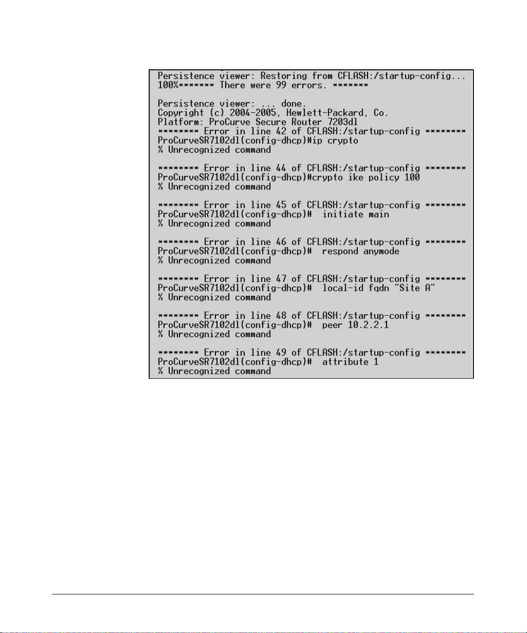
Overview
Managing Configuration Files Using a Text Editor
1-74
Figure 1-30. Boot Error Messages
The error messages in Figure 1-30 were displayed during bootup. In this
particular case, the startup-config file has VPNs configured, and the router
that is booting does not have the IPSec VPN module that enables these
commands. The VPN commands are reported as errors.
You can use error messages like these to locate and troubleshoot a problem
in the router’s configuration.
 Loading...