

Page 1

2810
ProCurve Series 2810 Switches
N.11.XX
Advanced Traffic
Management Guide
www.procurve.com
Page 2

Page 3

ProCurve Series 2810 Switches
July 2007
Advanced Traffic Management Guide
Page 4

© Copyright 2000-2007 Hewlett-Packard Development Company,
L.P. The information contained herein is subject to change without notice.
Publication Number
5991-4733
Ju
ly 2007
Applicable Products
ProCurve Switch 2810-24G - (J9021A)
ProCurve Switch 2810-48
G - (J9022A)
Trademark Credits
Microsoft, Windows, and Windows NT are US registered
trademarks of Microsoft Corporation.
Disclaimer
HEWLETT-PACKARD COMPANY MAKES NO WARRANTY
OF ANY KIND WITH REGARD TO THIS MATERIAL,
INCLUDING, BUT NOT LIMITED TO, THE IMPLIED
WARRANTIES OF MERCHANTABILITY AND FITNESS
FOR A PARTICULAR PURPOSE. Hewlett-Packard shall not
be liable for errors contained herein or for incidental or
consequential damages in connection with the furnishing,
performance, or use of this material.
The only warranties for HP products and services are set
forth in the express warranty statements accompanying
such products and services. Nothing herein should be
construed as constituting an additional warranty. HP shall
not be liable for technical or editorial errors or omissions
contained herein.
Hewlett-Packard assumes no responsibility for the use or
reliability of its software on equipment that is not furnished
by Hewlett-Packard.
Warranty
See the Customer Support/Warranty booklet included with
the product.
A copy of the specific warranty terms applicable to your
Hewlett-Packard products and replacement parts can be
obtained from your HP Sales and Service Office or
authorized dealer.
Hewlett-Packard Company
8000 Foothills Boulevard, m/s 5551
Roseville, California 95747-5551
http://www.procurve.com
Page 5

Contents
Product Documentation
About Your Switch Manual Set . . . . . . . . . . . . . . . . . . . . . . . . . . . . . . . . . . . . . xi
Feature Index . . . . . . . . . . . . . . . . . . . . . . . . . . . . . . . . . . . . . . . . . . . . . . . . . . .xii
1 Getting Started
Contents . . . . . . . . . . . . . . . . . . . . . . . . . . . . . . . . . . . . . . . . . . . . . . . . . . . . . . . 1-1
Introduction . . . . . . . . . . . . . . . . . . . . . . . . . . . . . . . . . . . . . . . . . . . . . . . . . . . 1-2
Conventions . . . . . . . . . . . . . . . . . . . . . . . . . . . . . . . . . . . . . . . . . . . . . . . . . . . 1-2
Feature Descriptions by Model . . . . . . . . . . . . . . . . . . . . . . . . . . . . . . . . 1-2
Command Syntax Statements . . . . . . . . . . . . . . . . . . . . . . . . . . . . . . . . . 1-2
Command Prompts . . . . . . . . . . . . . . . . . . . . . . . . . . . . . . . . . . . . . . . . . . 1-3
Screen Simulations . . . . . . . . . . . . . . . . . . . . . . . . . . . . . . . . . . . . . . . . . . 1-3
Port Identity Examples . . . . . . . . . . . . . . . . . . . . . . . . . . . . . . . . . . . . . . . 1-4
Sources for More Information . . . . . . . . . . . . . . . . . . . . . . . . . . . . . . . . . . . . 1-4
Need Only a Quick Start? . . . . . . . . . . . . . . . . . . . . . . . . . . . . . . . . . . . . . . . . 1-6
IP Addressing . . . . . . . . . . . . . . . . . . . . . . . . . . . . . . . . . . . . . . . . . . . . . . . 1-6
To Set Up and Install the Switch in Your Network . . . . . . . . . . . . . . . . 1-6
2 Static Virtual LANs (VLANs)
Contents . . . . . . . . . . . . . . . . . . . . . . . . . . . . . . . . . . . . . . . . . . . . . . . . . . . . . . . 2-1
Overview . . . . . . . . . . . . . . . . . . . . . . . . . . . . . . . . . . . . . . . . . . . . . . . . . . . . . . 2-2
Port-Based Virtual LANs (Static VLANs) . . . . . . . . . . . . . . . . . . . . . . . . . . . . 2-3
Overview of Using VLANs . . . . . . . . . . . . . . . . . . . . . . . . . . . . . . . . . . . . 2-6
VLAN Support and the Default VLAN . . . . . . . . . . . . . . . . . . . . . . . 2-6
The Primary VLAN . . . . . . . . . . . . . . . . . . . . . . . . . . . . . . . . . . . . . . . 2-6
Per-Port Static VLAN Configuration Options . . . . . . . . . . . . . . . . . 2-8
General Steps for Using VLANs . . . . . . . . . . . . . . . . . . . . . . . . . . . . 2-9
VLAN Operating Notes . . . . . . . . . . . . . . . . . . . . . . . . . . . . . . . . . . . 2-9
iii
Page 6

Multiple VLAN Considerations . . . . . . . . . . . . . . . . . . . . . . . . . . . . . . . . 2-9
Single-Forwarding Database Operation . . . . . . . . . . . . . . . . . . . . 2-11
Example of an Unsupported Configuration and How
to Correct It . . . . . . . . . . . . . . . . . . . . . . . . . . . . . . . . . . . . . . . . . . . 2-11
Multiple-Forwarding Database Operation . . . . . . . . . . . . . . . . . . 2-13
Menu: Configuring VLAN Parameters . . . . . . . . . . . . . . . . . . . . . . . . . . 2-14
To Change VLAN Support Settings . . . . . . . . . . . . . . . . . . . . . . . . 2-14
Adding or Editing VLAN Names . . . . . . . . . . . . . . . . . . . . . . . . . . . 2-16
Adding or Changing a VLAN Port Assignment . . . . . . . . . . . . . . . 2-17
CLI: Configuring VLAN Parameters . . . . . . . . . . . . . . . . . . . . . . . . . . . 2-19
Web: Viewing and Configuring VLAN Parameters . . . . . . . . . . . . . . . 2-25
802.1Q VLAN Tagging . . . . . . . . . . . . . . . . . . . . . . . . . . . . . . . . . . . . . . . 2-26
The Secure Management VLAN . . . . . . . . . . . . . . . . . . . . . . . . . . . . . . . 2-30
Preparation . . . . . . . . . . . . . . . . . . . . . . . . . . . . . . . . . . . . . . . . . . . . 2-32
Configuration . . . . . . . . . . . . . . . . . . . . . . . . . . . . . . . . . . . . . . . . . . 2-33
Operating Notes for Management VLANs . . . . . . . . . . . . . . . . . . . 2-33
Effect of VLANs on Other Switch Features . . . . . . . . . . . . . . . . . . . . . 2-34
Spanning Tree Operation with VLANs . . . . . . . . . . . . . . . . . . . . . 2-34
IP Interfaces . . . . . . . . . . . . . . . . . . . . . . . . . . . . . . . . . . . . . . . . . . . 2-35
VLAN MAC Addresses . . . . . . . . . . . . . . . . . . . . . . . . . . . . . . . . . . . 2-35
Port Trunks . . . . . . . . . . . . . . . . . . . . . . . . . . . . . . . . . . . . . . . . . . . . 2-35
Port Monitoring . . . . . . . . . . . . . . . . . . . . . . . . . . . . . . . . . . . . . . . . 2-36
VLAN Restrictions . . . . . . . . . . . . . . . . . . . . . . . . . . . . . . . . . . . . . . . . . . 2-36
Jumbo Packet Support . . . . . . . . . . . . . . . . . . . . . . . . . . . . . . . . . . . . . . 2-36
3 GVRP
Contents . . . . . . . . . . . . . . . . . . . . . . . . . . . . . . . . . . . . . . . . . . . . . . . . . . . . . . . 3-1
Overview . . . . . . . . . . . . . . . . . . . . . . . . . . . . . . . . . . . . . . . . . . . . . . . . . . . . . . 3-2
Introduction . . . . . . . . . . . . . . . . . . . . . . . . . . . . . . . . . . . . . . . . . . . . . . . . . . . 3-3
General Operation . . . . . . . . . . . . . . . . . . . . . . . . . . . . . . . . . . . . . . . . . . . 3-4
Per-Port Options for Handling GVRP “Unknown VLANs” . . . . . . . . . . 3-6
Per-Port Options for Dynamic VLAN Advertising and Joining . . . . . . 3-8
GVRP and VLAN Access Control . . . . . . . . . . . . . . . . . . . . . . . . . . . . . . 3-10
Port-Leave From a Dynamic VLAN . . . . . . . . . . . . . . . . . . . . . . . . 3-10
Planning for GVRP Operation . . . . . . . . . . . . . . . . . . . . . . . . . . . . . . . . 3-10
iv
Page 7

Configuring GVRP On a Switch . . . . . . . . . . . . . . . . . . . . . . . . . . . . . . . 3-11
Menu: Viewing and Configuring GVRP . . . . . . . . . . . . . . . . . . . . . 3-12
CLI: Viewing and Configuring GVRP . . . . . . . . . . . . . . . . . . . . . . . 3-13
Web: Viewing and Configuring GVRP . . . . . . . . . . . . . . . . . . . . . . 3-16
GVRP Operating Notes . . . . . . . . . . . . . . . . . . . . . . . . . . . . . . . . . . . . . . 3-17
4 Multimedia Traffic Control with IP Multicast (IGMP)
Contents . . . . . . . . . . . . . . . . . . . . . . . . . . . . . . . . . . . . . . . . . . . . . . . . . . . . . . . 4-1
Overview . . . . . . . . . . . . . . . . . . . . . . . . . . . . . . . . . . . . . . . . . . . . . . . . . . . . . . 4-2
General Operation and Features . . . . . . . . . . . . . . . . . . . . . . . . . . . . . . . . . . 4-3
IGMP Features . . . . . . . . . . . . . . . . . . . . . . . . . . . . . . . . . . . . . . . . . . . . . . 4-3
IGMP Terms . . . . . . . . . . . . . . . . . . . . . . . . . . . . . . . . . . . . . . . . . . . . . . . . 4-4
IGMP Operating Features . . . . . . . . . . . . . . . . . . . . . . . . . . . . . . . . . . . . . 4-5
Basic Operation . . . . . . . . . . . . . . . . . . . . . . . . . . . . . . . . . . . . . . . . . 4-5
Enhancements . . . . . . . . . . . . . . . . . . . . . . . . . . . . . . . . . . . . . . . . . . 4-5
CLI: Configuring and Displaying IGMP . . . . . . . . . . . . . . . . . . . . . . . . . . . . . 4-6
Web: Enabling or Disabling IGMP . . . . . . . . . . . . . . . . . . . . . . . . . . . . . . . . 4-11
How IGMP Operates . . . . . . . . . . . . . . . . . . . . . . . . . . . . . . . . . . . . . . . . . . . 4-11
IGMP Operating Notes . . . . . . . . . . . . . . . . . . . . . . . . . . . . . . . . . . . . . . 4-12
Displaying IGMP Data. . . . . . . . . . . . . . . . . . . . . . . . . . . . . . . . . . . 4-12
Supported Standards and RFCs . . . . . . . . . . . . . . . . . . . . . . . . . . . . . . 4-13
Operation With or Without IP Addressing . . . . . . . . . . . . . . . . . . . . . . 4-13
Automatic Fast-Leave IGMP . . . . . . . . . . . . . . . . . . . . . . . . . . . . . . . . . 4-14
Using Delayed Group Flush . . . . . . . . . . . . . . . . . . . . . . . . . . . . . . . . . . 4-17
Forced Fast-Leave IGMP . . . . . . . . . . . . . . . . . . . . . . . . . . . . . . . . . . . . 4-17
Setting Fast-Leave and Forced Fast-Leave from the CLI . . . . . . . . . . 4-17
Setting Forced Fast-Leave Using the MIB . . . . . . . . . . . . . . . . . . . 4-18
Listing the MIB-Enabled Forced Fast-Leave Configuration . . . . 4-18
Configuring Per-Port Forced Fast-Leave IGMP . . . . . . . . . . . . . . . . . . 4-20
Using the Switch as Querier . . . . . . . . . . . . . . . . . . . . . . . . . . . . . . . . . . . . . 4-21
Querier Operation . . . . . . . . . . . . . . . . . . . . . . . . . . . . . . . . . . . . . . . . . . 4-21
Excluding Multicast Addresses from IP Multicast Filtering . . . . . . . . . . . 4-22
5 Multiple Instance Spanning-Tree Operation
Contents . . . . . . . . . . . . . . . . . . . . . . . . . . . . . . . . . . . . . . . . . . . . . . . . . . . . . . . 5-1
v
Page 8

Overview . . . . . . . . . . . . . . . . . . . . . . . . . . . . . . . . . . . . . . . . . . . . . . . . . . . . . . 5-2
802.1s Multiple Spanning Tree Protocol (MSTP) . . . . . . . . . . . . . . . . . . . . . 5-6
MSTP Structure . . . . . . . . . . . . . . . . . . . . . . . . . . . . . . . . . . . . . . . . . . . . . 5-7
How MSTP Operates . . . . . . . . . . . . . . . . . . . . . . . . . . . . . . . . . . . . . . . . . 5-9
MST Regions . . . . . . . . . . . . . . . . . . . . . . . . . . . . . . . . . . . . . . . . . . . . 5-9
Regions, Legacy STP and RSTP Switches, and the Common
Spanning Tree (CST) . . . . . . . . . . . . . . . . . . . . . . . . . . . . . . . . . . . . 5-11
MSTP Operation with 802.1Q VLANs . . . . . . . . . . . . . . . . . . . . . . 5-11
Terminology . . . . . . . . . . . . . . . . . . . . . . . . . . . . . . . . . . . . . . . . . . . . . . . 5-12
Operating Rules . . . . . . . . . . . . . . . . . . . . . . . . . . . . . . . . . . . . . . . . . . . . 5-14
Transitioning from STP or RSTP to MSTP . . . . . . . . . . . . . . . . . . . . . . 5-15
Tips for Planning an MSTP Application . . . . . . . . . . . . . . . . . . . . . . . . 5-16
Steps for Configuring MSTP . . . . . . . . . . . . . . . . . . . . . . . . . . . . . . . . . 5-17
Configuring MSTP Operation Mode and Global Parameters . . . . . . . 5-19
Configuring MSTP Per Port . . . . . . . . . . . . . . . . . . . . . . . . . . . . . . . . . . 5-22
Configuring Per Port Parameters . . . . . . . . . . . . . . . . . . . . . . . . . . 5-23
Configuring BPDU Filtering . . . . . . . . . . . . . . . . . . . . . . . . . . . . . . 5-26
Configuring BPDU Protection . . . . . . . . . . . . . . . . . . . . . . . . . . . . 5-27
Configuring Loop Protection . . . . . . . . . . . . . . . . . . . . . . . . . . . . . 5-30
Configuring MST Instance Parameters . . . . . . . . . . . . . . . . . . . . . . . . . 5-32
Configuring MST Instance Per-Port Parameters . . . . . . . . . . . . . . . . . 5-35
Enabling or Disabling Spanning Tree Operation . . . . . . . . . . . . . . . . . 5-38
Enabling an Entire MST Region at Once or Exchanging
One Region Configuration for Another . . . . . . . . . . . . . . . . . . . . . . . . 5-38
Displaying MSTP Statistics and Configuration . . . . . . . . . . . . . . . . . . 5-40
Displaying MSTP Statistics . . . . . . . . . . . . . . . . . . . . . . . . . . . . . . . 5-40
Displaying the MSTP Configuration . . . . . . . . . . . . . . . . . . . . . . . 5-43
Operating Notes . . . . . . . . . . . . . . . . . . . . . . . . . . . . . . . . . . . . . . . . . . . . 5-48
Troubleshooting . . . . . . . . . . . . . . . . . . . . . . . . . . . . . . . . . . . . . . . . . . . 5-48
6 Quality of Service (QoS): Managing Bandwidth More
Effectively
Contents . . . . . . . . . . . . . . . . . . . . . . . . . . . . . . . . . . . . . . . . . . . . . . . . . . . . . . . 6-1
Introduction . . . . . . . . . . . . . . . . . . . . . . . . . . . . . . . . . . . . . . . . . . . . . . . . . . . 6-3
Terminology . . . . . . . . . . . . . . . . . . . . . . . . . . . . . . . . . . . . . . . . . . . . . . . . 6-6
Overview . . . . . . . . . . . . . . . . . . . . . . . . . . . . . . . . . . . . . . . . . . . . . . . . . . . 6-7
vi
Page 9

QoS Types for Prioritizing Outbound Packets . . . . . . . . . . . . . . . . . . . 6-9
Packet Types and Evaluation Order . . . . . . . . . . . . . . . . . . . . . . . 6-10
Preparation for Configuring QoS . . . . . . . . . . . . . . . . . . . . . . . . . . . . . . . . . 6-13
Steps for Configuring QoS on the Switch . . . . . . . . . . . . . . . . . . . 6-13
Planning a QoS Configuration . . . . . . . . . . . . . . . . . . . . . . . . . . . . . . . . 6-15
Prioritizing and Monitoring QoS Configuration Options . . . . . . 6-15
QoS Resource Usage and Monitoring . . . . . . . . . . . . . . . . . . . . . . 6-15
Planning and Monitoring Rule Usage . . . . . . . . . . . . . . . . . . . . . . 6-16
Managing QoS Resource Consumption . . . . . . . . . . . . . . . . . . . . . 6-16
Troubleshooting a Shortage of Resources . . . . . . . . . . . . . . . . . . 6-17
Using QoS Types To Configure QoS for Outbound Traffic . . . . . . . . . . . . 6-18
Viewing the QoS Configuration . . . . . . . . . . . . . . . . . . . . . . . . . . . . . . . 6-18
No Override . . . . . . . . . . . . . . . . . . . . . . . . . . . . . . . . . . . . . . . . . . . . 6-19
QoS UDP/TCP Priority . . . . . . . . . . . . . . . . . . . . . . . . . . . . . . . . . . . . . . 6-20
Assigning 802.1p Priority Based on TCP or UDP Port Number . 6-21
Assigning a DSCP Policy Based on TCP or UDP Port Number . 6-22
QoS IP-Device Priority . . . . . . . . . . . . . . . . . . . . . . . . . . . . . . . . . . . . . . 6-27
Assigning a Priority Based on IP Address . . . . . . . . . . . . . . . . . . . 6-28
Assigning a DSCP Policy Based on IP Address . . . . . . . . . . . . . . 6-29
QoS IP Type-of-Service (ToS) Policy and Priority . . . . . . . . . . . . . . . 6-33
Assigning an 802.1p Priority to IPv4 Packets on the Basis
of the ToS Precedence Bits . . . . . . . . . . . . . . . . . . . . . . . . . . . . . . . 6-34
Assigning an 802.1p Priority to IPv4 Packets on the Basis
of Incoming DSCP . . . . . . . . . . . . . . . . . . . . . . . . . . . . . . . . . . . . . . 6-35
Assigning a DSCP Policy on the Basis of the DSCP in IPv4
Packets Received from Upstream Devices . . . . . . . . . . . . . . . . . . 6-39
Details of QoS IP Type-of-Service . . . . . . . . . . . . . . . . . . . . . . . . . 6-43
QoS VLAN-ID (VID) Priority . . . . . . . . . . . . . . . . . . . . . . . . . . . . . . . . . 6-46
Assigning a Priority Based on VLAN-ID . . . . . . . . . . . . . . . . . . . . 6-46
Assigning a DSCP Policy Based on VLAN-ID (VID) . . . . . . . . . . . 6-48
QoS Interface (Source-Port) Priority . . . . . . . . . . . . . . . . . . . . . . . . . . 6-52
Assigning a Priority Based on Source-Port . . . . . . . . . . . . . . . . . . 6-52
Assigning a DSCP Policy Based on the Source-Port . . . . . . . . . . 6-54
Differentiated Services Codepoint (DSCP) Mapping . . . . . . . . . . . . . 6-58
Default Priority Settings for Selected Codepoints . . . . . . . . . . . . 6-59
Quickly Listing Non-Default Codepoint Settings . . . . . . . . . . . . . 6-60
Note On Changing a Priority Setting . . . . . . . . . . . . . . . . . . . . . . . . . . . 6-61
Example of Changing the Priority Setting on a Policy When
One or More QoS Types Are Currently Using the Policy . . . . . . 6-62
IP Multicast (IGMP) Interaction with QoS . . . . . . . . . . . . . . . . . . . . . . . . . 6-65
vii
Page 10

QoS Messages in the CLI . . . . . . . . . . . . . . . . . . . . . . . . . . . . . . . . . . . . . . . . 6-65
QoS Operating Notes and Restrictions . . . . . . . . . . . . . . . . . . . . . . . . . . . . 6-66
7 ProCurve Stack Management
Contents . . . . . . . . . . . . . . . . . . . . . . . . . . . . . . . . . . . . . . . . . . . . . . . . . . . . . . . 7-1
Overview . . . . . . . . . . . . . . . . . . . . . . . . . . . . . . . . . . . . . . . . . . . . . . . . . . . . . . 7-3
Operation . . . . . . . . . . . . . . . . . . . . . . . . . . . . . . . . . . . . . . . . . . . . . . . . . . . . . . 7-4
Which Devices Support Stacking? . . . . . . . . . . . . . . . . . . . . . . . . . . . . . 7-5
Components of ProCurve Stack Management . . . . . . . . . . . . . . . . . . . . 7-6
General Stacking Operation . . . . . . . . . . . . . . . . . . . . . . . . . . . . . . . . . . . 7-6
Operating Rules for Stacking . . . . . . . . . . . . . . . . . . . . . . . . . . . . . . . . . . 7-8
General Rules . . . . . . . . . . . . . . . . . . . . . . . . . . . . . . . . . . . . . . . . . . . 7-8
Specific Rules . . . . . . . . . . . . . . . . . . . . . . . . . . . . . . . . . . . . . . . . . . . 7-9
Configuring Stack Management . . . . . . . . . . . . . . . . . . . . . . . . . . . . . . . . . . 7-10
Overview of Configuring and Bringing Up a Stack . . . . . . . . . . . . . . . 7-10
General Steps for Creating a Stack . . . . . . . . . . . . . . . . . . . . . . . . 7-12
Using the Menu Interface To View Stack Status
and Configure Stacking . . . . . . . . . . . . . . . . . . . . . . . . . . . . . . . . . . . . . 7-14
Using the Menu Interface To View and Configure
a Commander Switch . . . . . . . . . . . . . . . . . . . . . . . . . . . . . . . . . . . 7-14
Using the Menu To Manage a Candidate Switch . . . . . . . . . . . . . 7-16
Using the Commander To Manage The Stack . . . . . . . . . . . . . . . . . . . 7-18
Using the Commander To Access Member Switches for
Configuration Changes and Monitoring Traffic . . . . . . . . . . . . . . 7-25
Converting a Commander or Member to a Member
of Another Stack . . . . . . . . . . . . . . . . . . . . . . . . . . . . . . . . . . . . . . . 7-26
Monitoring Stack Status . . . . . . . . . . . . . . . . . . . . . . . . . . . . . . . . . . . . . 7-27
Using the CLI To View Stack Status and Configure Stacking . . . . . . 7-31
Using the CLI To View Stack Status . . . . . . . . . . . . . . . . . . . . . . . 7-33
Using the CLI To Configure a Commander Switch . . . . . . . . . . . 7-35
Adding to a Stack or Moving Switches Between Stacks . . . . . . . 7-37
Using the CLI To Remove a Member from a Stack . . . . . . . . . . . 7-42
Using the CLI To Access Member Switches for Configuration
Changes and Traffic Monitoring . . . . . . . . . . . . . . . . . . . . . . . . . . . 7-44
SNMP Community Operation in a Stack . . . . . . . . . . . . . . . . . . . . . . . 7-45
Using the CLI To Disable or Re-Enable Stacking . . . . . . . . . . . . . . . . 7-46
Transmission Interval . . . . . . . . . . . . . . . . . . . . . . . . . . . . . . . . . . . . . . . 7-46
Stacking Operation with Multiple VLANs Configured . . . . . . . . . . . . 7-46
viii
Page 11

Web: Viewing and Configuring Stacking . . . . . . . . . . . . . . . . . . . . . . . 7-47
Status Messages . . . . . . . . . . . . . . . . . . . . . . . . . . . . . . . . . . . . . . . . . . . . 7-48
Index
ix
Page 12

x
Page 13

Product Documentation
About Your Switch Manual Set
The switch manual set includes the following:
■ Read Me First - a printed guide shipped with your switch. Provides
software update information, product notes, and other information.
■ Installation and Getting Started Guide - a printed guide shipped
with your switch. This guide explains how to prepare for and perform
the physical installation and connection to your network.
■ Management and Configuration Guide - a PDF file on the
ProCurve Networking website. This guide describes how to
configure, manage, and monitor basic switch operation.
■ Advanced Traffic Management Guide - a PDF file on the ProCurve
Networking website. This guide explains the configuration and
operation of traffic management features such as spanning tree and
VLANs.
■ Access Security Guide - a PDF file on the ProCurve Networking
website. This guide explains the configuration and operation of
access security and user authentication features on the switch.
■ Release Notes - posted on the ProCurve web site to provide
information on software updates. The release notes describe new
features, fixes, and enhancements that become available between
revisions of the above guides.
Note For the latest version of all ProCurve switch documentation, including release
notes covering recently added features, visit the ProCurve Networking
website at http://www.procurve.com. Click on Technical support, and then
click on Product manuals.
xi
Page 14

Product Documentation
Feature Index
For the manual set supporting your switch model, the following feature index
indicates which manual to consult for information on a given software feature.
Feature Management and
Configuration
802.1Q VLAN Tagging - X -
802.1p Priority X - -
802.1X Authentication - - X
Authorized IP Managers - - X
Config File X --
Copy Command X - -
Debug X --
DHCP Configuration - X -
DHCP/Bootp Operation X --
Diagnostic Tools X - -
Downloading Software X --
Event Log X - -
Factory Default Settings X --
File Management X - -
Advanced Traffic
Management
Access Security
Guide
File Transfers X --
GVRP - X -
IGMP - X -
Interface Access (Telnet, Console/Serial, Web) X - -
IP Addressing X --
LACP X - -
Link X --
xii
Page 15

Product Documentation
Feature Management and
Configuration
LLDP X - -
MAC Address Management X --
MAC Lockdown - - X
MAC Lockout - - X
MAC-based Authentication - - X
Monitoring and Analysis X --
Multicast Filtering - X -
Network Management Applications (LLDP, SNMP) X --
Passwords - - X
Ping X --
Port Configuration X - -
Port Security - - X
Port Status X - -
Port Trunking (LACP) X --
Advanced Traffic
Management
Access Security
Guide
Port-Based Access Control - - X
Port-Based Priority (802.1Q) X --
Quality of Service (QoS) - X -
RADIUS Authentication and Accounting - - X
Secure Copy X - -
SFTP X --
SNMP X - -
Software Downloads (SCP/SFTP, TFTP, Xmodem) X --
Source-Port Filters - - X
Spanning Tree (MSTP) - X -
SSH (Secure Shell) Encryption - - X
SSL (Secure Socket Layer) - - X
xiii
Page 16

Product Documentation
Feature Management and
Configuration
Stack Management (Stacking) - X -
Syslog X --
System Information X - -
TACACS+ Authentication - - X
Telnet Access X - -
TFTP X --
Time Protocols (TimeP, SNTP) X - -
Traffic/Security Filters - - X
Troubleshooting X - -
VLANs - X -
Web-based Authentication - - X
Xmodem X --
Advanced Traffic
Management
Access Security
Guide
xiv
Page 17

Getting Started
Contents
Introduction . . . . . . . . . . . . . . . . . . . . . . . . . . . . . . . . . . . . . . . . . . . . . . . . . . . 1-2
Conventions . . . . . . . . . . . . . . . . . . . . . . . . . . . . . . . . . . . . . . . . . . . . . . . . . . . 1-2
Feature Descriptions by Model . . . . . . . . . . . . . . . . . . . . . . . . . . . . . . . . 1-2
Command Syntax Statements . . . . . . . . . . . . . . . . . . . . . . . . . . . . . . . . . 1-2
Command Prompts . . . . . . . . . . . . . . . . . . . . . . . . . . . . . . . . . . . . . . . . . . 1-3
Screen Simulations . . . . . . . . . . . . . . . . . . . . . . . . . . . . . . . . . . . . . . . . . . 1-3
Port Identity Examples . . . . . . . . . . . . . . . . . . . . . . . . . . . . . . . . . . . . . . . 1-4
Sources for More Information . . . . . . . . . . . . . . . . . . . . . . . . . . . . . . . . . . . . 1-4
Need Only a Quick Start? . . . . . . . . . . . . . . . . . . . . . . . . . . . . . . . . . . . . . . . . 1-6
IP Addressing . . . . . . . . . . . . . . . . . . . . . . . . . . . . . . . . . . . . . . . . . . . . . . . 1-6
To Set Up and Install the Switch in Your Network . . . . . . . . . . . . . . . . 1-6
1
1-1
Page 18

Getting Started
Introduction
Introduction
This Advanced Traffic Management Guide describes how to manage and
configure advanced traffic management features on your switch. It supports
the following switches:
■ ProCurve Switch 2810
For an overview of other product documentation for the above switches, refer
to “Product Documentation” on page xi.
You can download a copy from the ProCurve Networking website, http://
www.procurve.com.
Conventions
This guide uses the following conventions for command syntax and displayed
information.
Feature Descriptions by Model
In cases where a software feature is not available in all of the switch models
covered by this guide, the section heading specifically indicates which product
or product series offer the feature.
For example (the switch model is highlighted here in bold italics):
“Jumbo Packet Support on the 2810 Switch”.
Command Syntax Statements
Syntax: aaa port-access authenticator < port-list >
[ control < authorized | auto | unauthorized >]
■ Vertical bars ( | ) separate alternative, mutually exclusive elements.
■ Square brackets ( [ ] ) indicate optional elements.
■ Braces ( < > ) enclose required elements.
1-2
Page 19

Getting Started
Conventions
■ Braces within square brackets ( [ < > ] ) indicate a required element
within an optional choice.
■ Boldface indicates use of a CLI command, part of a CLI command
syntax, or other displayed element in general text. For example:
“Use the copy tftp command to download the key from a TFTP server.”
■ Italics indicate variables for which you must supply a value when
executing the command. For example, in this command syntax, < port-
list > indicates that you must provide one or more port numbers:
Syntax: aaa port-access authenticator < port-list >
Command Prompts
In the default configuration, your switch displays one of the following CLI
prompts:
ProCurve Switch 2810#
To simplify recognition, this guide uses ProCurve to represent command
prompts for all models. For example:
ProCurve#
(You can use the hostname command to change the text in the CLI prompt.)
Screen Simulations
Figures containing simulated screen text and command output look like this:
ProCurve(config)# show version
Image stamp: /sw/code/build/bass(ppne_swt)
Mar 17 2006 11:44:02
N.10.XX
2624
Boot Image: Primary
Build Options: QA
Watchdog: ENABLED
Figure 1-1. Example of a Figure Showing a Simulated Screen
1-3
Page 20

Getting Started
Sources for More Information
In some cases, brief command-output sequences appear outside of a
numbered figure. For example:
ProCurve(config)# ip default-gateway 18.28.152.1/24
ProCurve(config)# vlan 1 ip address 18.28.36.152/24
ProCurve(config)# vlan 1 ip igmp
Port Identity Examples
This guide describes software applicable to both chassis-based and stackable
ProCurve switches. Where port identities are needed in an example, this guide
uses the chassis-based port identity system, such as “A1”, “B3 - B5”, “C7”, etc.
However, unless otherwise noted, such examples apply equally to the
stackable switches, which for port identities typically use only numbers, such
as “1”, “3-5”, “15”, etc.
Sources for More Information
For additional information about switch operation and features not covered
in this guide, consult the following sources:
■ For information on which product manual to consult on a given
software feature, refer to “Product Documentation” on page xi.
Note For the latest version of all ProCurve switch documentation, including
release notes covering recently added features, visit the ProCurve
Networking website at http://www.procurve.com. Click on Technical
support, and then click on Product manuals.
■ For information on specific parameters in the menu interface, refer
to the online help provided in the interface. For example:
1-4
Page 21

Sources for More Information
Getting Started
Online Help
for Menu
Figure 1-2. Getting Help in the Menu Interface
■ For information on a specific command in the CLI, type the command
name followed by “help”. For example:
Figure 1-3. Getting Help in the CLI
■ For information on specific features in the Web browser interface,
use the online help. For more information, refer to the Management
and Configuration Guide for your switch.
■ For further information on ProCurve Networking switch technology,
visit the ProCurve Networking website at:
http://www.procurve.com
1-5
Page 22

Getting Started
Need Only a Quick Start?
Need Only a Quick Start?
IP Addressing
If you just want to give the switch an IP address so that it can communicate
on your network, or if you are not using multiple VLANs, ProCurve
recommends that you use the Switch Setup screen to quickly configure IP
addressing. To do so, do one of the following:
■ Enter setup at the CLI Manager level prompt.
ProCurve# setup
■ In the Main Menu of the Menu interface, select
8. Run Setup
For more on using the Switch Setup screen, see the Quick Installation Guide
you received with the switch.
To Set Up and Install the Switch in Your Network
Important! Use the Quick Installation Guide shipped with your switch for the following:
■ Notes, cautions, and warnings related to installing and using the
switch
■ Instructions for physically installing the switch in your network
■ Quickly assigning an IP address and subnet mask, setting a Manager
password, and (optionally) configuring other basic features.
■ Interpreting LED behavior.
For the latest version of the Installation and Getting Started Guide and other
documentation for your switch, visit the ProCurve Networking Web site.
(Refer to “Product Documentation” on page xi of this guide for further
details.)
1-6
Page 23

Static Virtual LANs (VLANs)
Contents
Overview . . . . . . . . . . . . . . . . . . . . . . . . . . . . . . . . . . . . . . . . . . . . . . . . . . . . . . 2-2
Port-Based Virtual LANs (Static VLANs) . . . . . . . . . . . . . . . . . . . . . . . . . . . . 2-3
Overview of Using VLANs . . . . . . . . . . . . . . . . . . . . . . . . . . . . . . . . . . . . 2-6
VLAN Support and the Default VLAN . . . . . . . . . . . . . . . . . . . . . . . 2-6
The Primary VLAN . . . . . . . . . . . . . . . . . . . . . . . . . . . . . . . . . . . . . . . 2-6
Per-Port Static VLAN Configuration Options . . . . . . . . . . . . . . . . . 2-8
General Steps for Using VLANs . . . . . . . . . . . . . . . . . . . . . . . . . . . . 2-9
VLAN Operating Notes . . . . . . . . . . . . . . . . . . . . . . . . . . . . . . . . . . . 2-9
Multiple VLAN Considerations . . . . . . . . . . . . . . . . . . . . . . . . . . . . . . . . 2-9
Single-Forwarding Database Operation . . . . . . . . . . . . . . . . . . . . 2-11
Example of an Unsupported Configuration and How
to Correct It . . . . . . . . . . . . . . . . . . . . . . . . . . . . . . . . . . . . . . . . . . . 2-11
Multiple-Forwarding Database Operation . . . . . . . . . . . . . . . . . . 2-13
Menu: Configuring VLAN Parameters . . . . . . . . . . . . . . . . . . . . . . . . . . 2-14
To Change VLAN Support Settings . . . . . . . . . . . . . . . . . . . . . . . . 2-14
Adding or Editing VLAN Names . . . . . . . . . . . . . . . . . . . . . . . . . . . 2-16
Adding or Changing a VLAN Port Assignment . . . . . . . . . . . . . . . 2-17
CLI: Configuring VLAN Parameters . . . . . . . . . . . . . . . . . . . . . . . . . . . 2-19
Web: Viewing and Configuring VLAN Parameters . . . . . . . . . . . . . . . 2-25
802.1Q VLAN Tagging . . . . . . . . . . . . . . . . . . . . . . . . . . . . . . . . . . . . . . . 2-26
The Secure Management VLAN . . . . . . . . . . . . . . . . . . . . . . . . . . . . . . . 2-30
Preparation . . . . . . . . . . . . . . . . . . . . . . . . . . . . . . . . . . . . . . . . . . . . 2-32
Configuration . . . . . . . . . . . . . . . . . . . . . . . . . . . . . . . . . . . . . . . . . . 2-33
Operating Notes for Management VLANs . . . . . . . . . . . . . . . . . . . 2-33
Effect of VLANs on Other Switch Features . . . . . . . . . . . . . . . . . . . . . 2-34
Spanning Tree Operation with VLANs . . . . . . . . . . . . . . . . . . . . . 2-34
IP Interfaces . . . . . . . . . . . . . . . . . . . . . . . . . . . . . . . . . . . . . . . . . . . 2-35
VLAN MAC Addresses . . . . . . . . . . . . . . . . . . . . . . . . . . . . . . . . . . . 2-35
Port Trunks . . . . . . . . . . . . . . . . . . . . . . . . . . . . . . . . . . . . . . . . . . . . 2-35
Port Monitoring . . . . . . . . . . . . . . . . . . . . . . . . . . . . . . . . . . . . . . . . 2-36
VLAN Restrictions . . . . . . . . . . . . . . . . . . . . . . . . . . . . . . . . . . . . . . . . . . 2-36
Jumbo Packet Support . . . . . . . . . . . . . . . . . . . . . . . . . . . . . . . . . . . . . . 2-36
2
2-1
Page 24

Static Virtual LANs (VLANs)
Overview
Overview
This chapter describes how to configure and use static, port-based VLANs on
the switches covered by this manual.
For general information on how to use the switch’s built-in interfaces, refer
to these chapters in the Management and Configuration Guide for your
switch:
■ Chapter 3, “Using the Menu Interface”
■ Chapter 4, “Using the Command Line Interface (CLI)”
■ Chapter 5, “Using the Web Browser Interface”
■ Chapter 6, “Switch Memory and Configuration”
2-2
Page 25

Port-Based Virtual LANs (Static VLANs)
Static Virtual LANs (VLANs)
Port-Based Virtual LANs (Static VLANs)
VLAN Features
Feature Default Menu CLI Web
view existing VLANs n/a page 2-14
thru 2-19
configuring static
VLANs
configuring dynamic
VLANs
default VLAN with
VID = 1
disabled See the chapter on GVRP in this
page 2-14
thru 2-19
manual.
A VLAN is a group of ports designated by the switch as belonging to the same
broadcast domain. (That is, all ports carrying traffic for a particular subnet
address would normally belong to the same VLAN.)
Note This chapter describes static VLANs, which are VLANs you manually config-
ure with a name, VLAN ID (VID), and port assignments. (For information on
dynamic VLANs, see chapter 3, “GVRP”.)
page 2-20 page 2-25
page 2-19 page 2-25
Using a VLAN, you can group users by logical function instead of physical
location. This helps to control bandwidth usage by allowing you to group highbandwidth users on low-traffic segments and to organize users from different
LAN segments according to their need for common resources.
By default, 802.1Q VLAN support is enabled for eight VLANS. You can configure up to 256 VLANs on the switch.
(802.1Q compatibility enables you to assign each switch port to multiple
VLANs, if needed, and the port-based nature of the configuration allows
interoperation with older switches that require a separate port for each
VLAN.)
General Use and Operation. Port-based VLANs are typically used to
reduce broadcast traffic and to increase security. A group of network users
assigned to a VLAN forms a broadcast domain that is separate from other
VLANs that may be configured on a switch. On a given switch, packets are
forwarded only between ports that belong to the same VLAN. Thus, all ports
carrying traffic for a particular subnet address should be configured to the
same VLAN. Cross-domain broadcast traffic in the switch is eliminated and
2-3
Page 26
Static Virtual LANs (VLANs)
Port-Based Virtual LANs (Static VLANs)
bandwidth is saved by not allowing packets to flood out all ports. Separate
VLANs on the switch can communicate with each other through an external
router.
For example, referring to figure 2-1, if ports A1 through A4 belong to VLAN_1
and ports A5 through A8 belong to VLAN_2, traffic from end-node stations on
ports A2 through A4 is restricted to only VLAN_1, while traffic from ports A5
through A7 is restricted to only VLAN_2. For nodes on VLAN_1 to communicate with VLAN_2, their traffic must go through an external router via ports
A1 and A8.
External
Router
Switch with Two
VLANs Configured
VLAN_1
Port A1
Port A8
VLAN_2
Port A2
Port A3
Port A4
Port A5
Port A6
Port A7
2-4
Figure 2-1. Example of Routing Between VLANs via an External Router
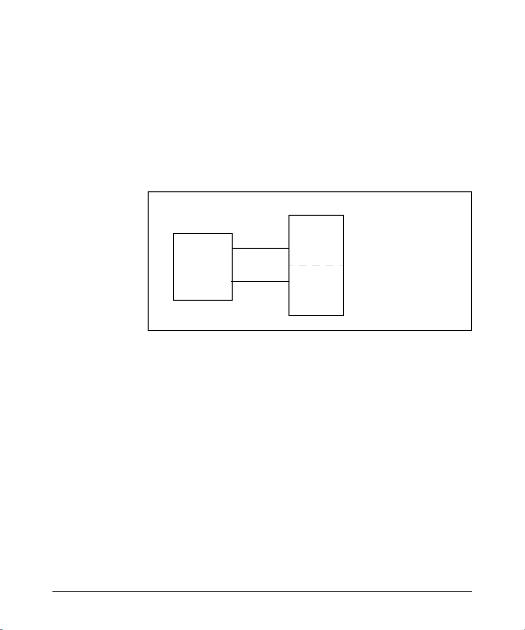
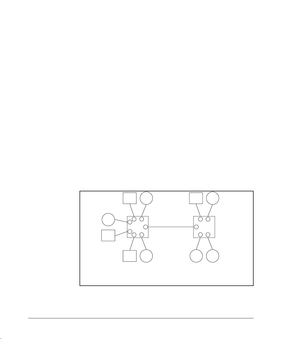
Overlapping (Tagged) VLANs. A port on the switch can be a member of
more than one VLAN if the device to which it is connected complies with the
802.1Q VLAN standard. For example, a port connected to a central server using
a network interface card (NIC) that complies with the 802.1Q standard can be
a member of multiple VLANs, allowing members of multiple VLANs to use the
server. Although these VLANs cannot communicate with each other through
the server, they can all access the server over the same connection from the
switch. Where VLANs overlap in this way, VLAN “tags” are used to distinguish
between traffic from different VLANs.
Page 27
Port-Based Virtual LANs (Static VLANs)
ProCurve Switch
Static Virtual LANs (VLANs)
Figure 2-2. Example of Overlapping VLANs Using the Same Server
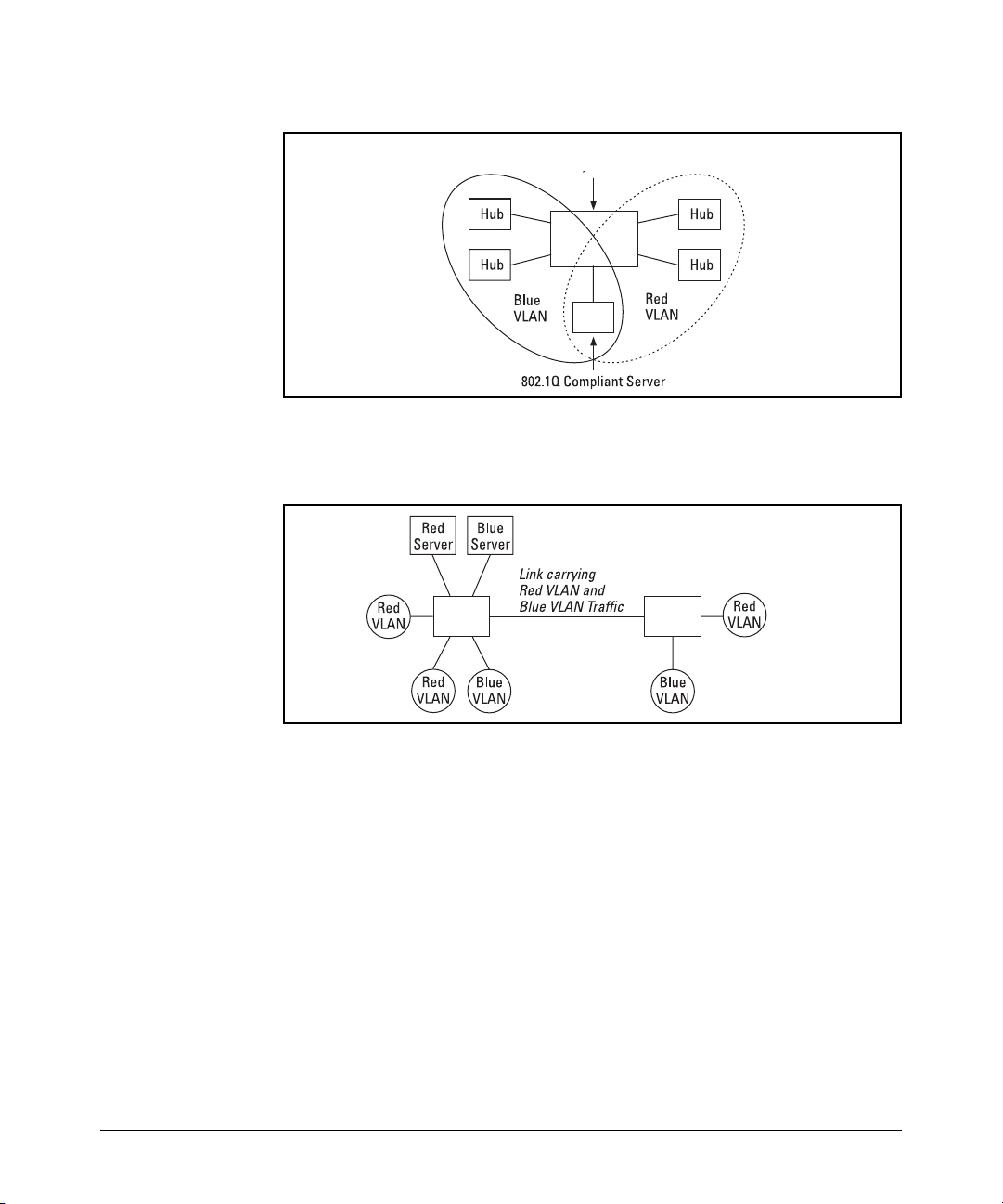
Similarly, using 802.1Q-compliant switches, you can connect multiple VLANs
through a single switch-to-switch link.
ProCurve
Switch
ProCurve
Switch
Figure 2-3. Example of Connecting Multiple VLANs Through the Same Link
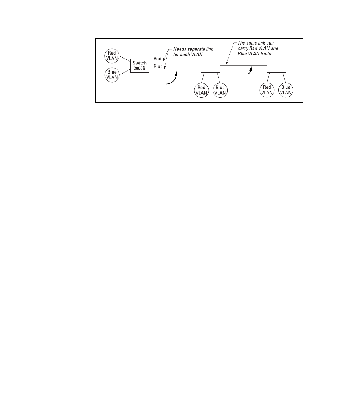
Introducing Tagged VLAN Technology into Networks Running Legacy
(Untagged) VLANs. You can introduce 802.1Q-compliant devices into net-
works that have built untagged VLANs based on earlier VLAN technology. The
fundamental rule is that legacy/untagged VLANs require a separate link for
each VLAN, while 802.1Q, or tagged VLANs can combine several VLANs in one
link. This means that on the 802.1Q-compliant device, separate ports (configured as untagged) must be used to connect separate VLANs to non-802.1Q
devices.
2-5
Page 28
Static Virtual LANs (VLANs)
Port-Based Virtual LANs (Static VLANs)
Switch
2524
Figure 2-4. Example of Tagged and Untagged VLAN Technology in the Same
Network
For more information on VLANs, refer to:
■ “Overview of Using VLANs” (page 2-6)
■ “Menu: Configuring VLAN Parameters (page 2-14)
■ “CLI: Configuring VLAN Parameters” (page 2-14)
■ “Web: Viewing and Configuring VLAN Parameters” (page 2-25)
■ “VLAN Tagging Information” (page 2-26)
■ “Effect of VLANs on Other Switch Features” (page 2-34)
■ “VLAN Restrictions” (page 2-36)
Untagged VLAN Links
Non-802.1Q-
compliant switch
ProCurve
Switch
Tagged VLAN
Link
Switch
ProCurve
Switch
2-6
Overview of Using VLANs
VLAN Support and the Default VLAN
In the factory default configuration, all ports on the switch belong to the
default VLAN (named DEFAULT_VLAN). This places all ports in the switch
into one physical broadcast domain. In the factory-default state, the default
VLAN is the primary VLAN.
You can partition the switch into multiple virtual broadcast domains by adding
one or more additional VLANs and moving ports from the default VLAN to the
new VLANs. You can change the name of the default VLAN, but you cannot
change the default VLAN’s VID (which is always “1”). Although you can remove
all ports from the default VLAN, this VLAN is always present; that is, you
cannot delete it from the switch.
The Primary VLAN
Because certain features and management functions, such as single IPaddress stacking, run on only one VLAN in the switch, and because DHCP and
Bootp can run per-VLAN, there is a need for a dedicated VLAN to manage these
Page 29

Port-Based Virtual LANs (Static VLANs)
Static Virtual LANs (VLANs)
features and ensure that multiple instances of DHCP or Bootp on different
VLANs do not result in conflicting configuration values for the switch. The
primary VLAN is the VLAN the switch uses to run and manage these features
and data. In the factory-default configuration, the switch designates the
default VLAN (DEFAULT_VLAN) as the primary VLAN. However, to provide
more control in your network, you can designate another VLAN as primary.
To summarize, designating a non-default VLAN as primary means that:
■ The stacking feature runs on the switch’s designated primary VLAN
instead of the default VLAN
■ The switch reads DHCP responses on the primary VLAN instead of on the
default VLAN. (This includes such DHCP-resolved parameters as the
TimeP server address, Default TTL, and IP addressing—including the
Gateway IP address—when the switch configuration specifies DHCP as
the source for these values.)
■ The default VLAN continues to operate as a standard VLAN (except, as
noted above, you cannot delete it or change its VID).
■ Any ports not specifically assigned to another VLAN will remain assigned
to the Default VLAN, regardless of whether it is the primary VLAN.
Candidates for primary VLAN include any static VLAN currently configured
on the switch. (A dynamic—GVRP-learned—VLAN that has not been converted to a static VLAN cannot be the primary VLAN.) To display the current
primary VLAN, use the CLI show vlan command.
Note If you configure a non-default VLAN as the primary VLAN, you cannot delete
that VLAN unless you first select a different VLAN to act as primary.
If you manually configure a gateway on the switch, it will ignore any gateway
address received via DHCP or Bootp.
2-7
Page 30
Static Virtual LANs (VLANs)
Port-Based Virtual LANs (Static VLANs)
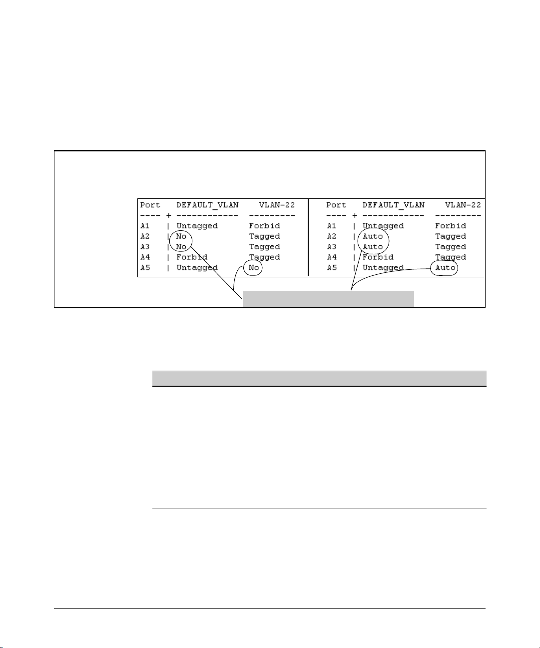
Per-Port Static VLAN Configuration Options
The following figure and table show the options you have for assigning
individual ports to a static VLAN. Note that GVRP, if configured, affects these
options and VLAN behavior on the switch. The display below shows the perport VLAN configuration options. Table 2-1 briefly describes these options.
Example of Per-Port
VLAN Configuration
with GVRP Disabled
(the default)
Enabling GVRP causes “No” to display as “Auto”.
Figure 2-5. Comparing Per-Port VLAN Options With and Without GVRP
Example of Per-Port
VLAN Configuration
with GVRP Enabled
2-8
Table 2-1. Per-Port VLAN Configuration Options
Parameter Effect on Port Participation in Designated VLAN
Tagged
Untagged
No
- or -
Auto
Forbid
Allows the port to join multiple VLANs.
Allows VLAN connection to a device that is configured for an untagged
VLAN instead of a tagged VLAN. The switch allows no more than one
untagged VLAN assignment per port.
: Appears when the switch is not GVRP-enabled; prevents the port from
No
joining that VLAN.
Auto: Appears when GVRP is enabled on the switch; allows the port to
dynamically join any advertised VLAN that has the same VID
Prevents the port from joining the VLAN, regardless of whether GVRP is
enabled on the switch.
Page 31

Port-Based Virtual LANs (Static VLANs)
Static Virtual LANs (VLANs)
General Steps for Using VLANs
1. Plan your VLAN strategy and create a map of the logical topology that will
result from configuring VLANs. Include consideration for the interaction
between VLANs and other features such as Spanning Tree Protocol, load
balancing, and IGMP. (Refer to “Effect of VLANs on Other Switch Features” on page 2-34.) If you plan on using dynamic VLANs, include the port
configuration planning necessary to support this feature. (See chapter 3,
“GVRP”.)
By default, VLAN support is enabled and the switch is configured for eight
VLANs.
2. Configure at least one VLAN in addition to the default VLAN.
3. Assign the desired switch ports to the new VLAN(s).
4. If you are managing VLANs with SNMP in an IP network, each VLAN must
have an IP address. Refer to the chapter on IP addressing in the Manage-
ment and Configuration Guide.
VLAN Operating Notes
■ If you are using DHCP/Bootp to acquire the switch’s configuration, packet
time-to-live, and TimeP information, you must designate the VLAN on
which DHCP is configured for this purpose as the primary VLAN. (In the
factory-default configuration, the DEFAULT_VLAN is the primary VLAN.)
■ IGMP, and some other features operate on a “per VLAN” basis. This means
you must configure such features separately for each VLAN in which you
want them to operate.
■ You can rename the default VLAN, but you cannot change its VID (1) or
delete it from the switch.
■ Any ports not specifically assigned to another VLAN will remain assigned
to the DEFAULT_VLAN.
■ To delete a VLAN from the switch, you must first remove from that VLAN
any ports assigned to it.
■ Changing the number of VLANs supported on the switch requires a reboot.
Other VLAN configuration changes are dynamic.
Multiple VLAN Considerations
Switches use a forwarding database to maintain awareness of which external
devices are located on which VLANs. Some switches, such as those covered
by this guide, have a multiple-forwarding database, which means the switch
allows multiple database entries of the same MAC address, with each entry
2-9
Page 32

Static Virtual LANs (VLANs)
Port-Based Virtual LANs (Static VLANs)
showing the (different) source VLAN and source port. Other switch models
have a single-forwarding database, which means they allow only one database entry of a unique MAC address, along with the source VLAN and source
port on which it is found (see Table 2-6). Not all VLANs on a switch covered
by this guide use the same MAC address (see “VLAN MAC Addresses” on page
2-35). Connecting multiple-forwarding database switch to a single-forwarding
database switch where multiple VLANs exist imposes some cabling and port
VLAN assignment restrictions. Table 2-6 illustrates the functional difference
between the two database types.
Table 2-6. Example of Forwarding Database Content
Multiple-Forwarding Database Single-Forwarding Database
MAC Address Destination
0004ea-84d9f4 1 A5 0004ea-84d9f4 100 A9
0004ea-84d9f4 22 A12 0060b0-880af9 105 A10
0004ea-84d9f4 44 A20 0060b0-880a81 107 A17
0060b0-880a81 33 A20
This database allows multiple destinations
for the same MAC address. If the switch
detects a new destination for an existing
MAC entry, it just adds a new instance of that
MAC to the table.
VLAN ID
Destination
Port
MAC Address Destination
VLAN ID
This database allows only one destination
for a MAC address. If the switch detects a
new destination for an existing MAC entry,
it replaces the existing MAC instance with
a new instance showing the new
destination.
Destination
Port
2-10
Table 2-7 lists the database structure of current ProCurve switch models.
Table 2-7. Forwarding Database Structure for Managed ProCurve Switches
Multiple-Forwarding Databases* Single-Forwarding Database*
Switch 6108 Switch 1600M/2400M/2424M
Series 5300xl switches Switch 4000M/8000M
Series 4100gl switches Series 2500 switches
Series 3400cl switches Switch 800T
Switch 2810 Switch 2000
Series 2800 switches x
Series 2600/2600-PWR switches
*To determine whether other vendors’ devices use single-forwarding
or multiple-forwarding database architectures, refer to the
documentation provided for those devices.
Page 33

Port-Based Virtual LANs (Static VLANs)
Static Virtual LANs (VLANs)
Single-Forwarding Database Operation
When a packet arrives with a destination MAC address that matches a MAC
address in the switch’s forwarding table, the switch tries to send the packet
to the port listed for that MAC address. But, if the destination port is in a
different VLAN than the VLAN on which the packet was received, the switch
drops the packet. This is not a problem for a switch with a multiple-forwarding
database (refer to table 2-7, above) because the switch allows multiple
instances of a given MAC address; one for each valid destination. However, a
switch with a single-forwarding database allows only one instance of a given
MAC address. If (1) you connect the two types of switches through multiple
ports or trunks belonging to different VLANs, and (2) enable routing on the
switch having the multiple-forwarding database; then, on the switch having
the single-forwarding database, the port and VLAN record it maintains for the
connected multiple-forwarding-database switch can frequently change. This
causes poor performance and the appearance of an intermittent or broken
connection.
Example of an Unsupported Configuration and How to Correct It
The Problem. In figure 2-1, the MAC address table for Switch 8000M will
sometimes record the multiple-forwarding database switch as accessed on
port A1 (VLAN 1), and other times as accessed on port B1 (VLAN 2):
Switch 8000M
VLANs.)
VLAN 2
B1
D1
VLAN 2
PC “B”
This switch has a single
forwarding database.
This switch has multiple
forwarding databases.
PC “A”
VLAN 1
A1
C1
VLAN 1
Multiple-Forwarding
Database Switch
Routing Enabled
(Same MAC address for all
Figure 2-1. Example of Invalid Configuration for Single-Forwarding to MultipleForwarding Database Devices in a Multiple VLAN Environment
In figure 2-1, PC “A” sends an IP packet to PC “B”.
2-11
Page 34

Static Virtual LANs (VLANs)
Port-Based Virtual LANs (Static VLANs)
1. The packet enters VLAN 1 in the Switch 8000 with the multiple-forwarding
database switch MAC address in the destination field. Because the 8000M
has not yet learned this MAC address, it does not find the address in its
address table, and floods the packet out all ports, including the VLAN 1
link (port “A1”) to the multiple-forwarding database switch. The multipleforwarding database switch then routes the packet through the VLAN 2
link to the 8000M, which forwards the packet on to PC “B”. Because the
8000M received the packet from the multiple-forwarding database switch
on VLAN 2 (port “B1”), the 8000M’s single forwarding database records
the multiple-forwarding database switch as being on port “B1” (VLAN 2).
2. PC “A” now sends a second packet to PC “B”. The packet again enters
VLAN 1 in the Switch 8000 with the multiple-forwarding database switch’s
MAC address in the destination field. However, this time the Switch
8000M’s single forwarding database indicates that the multiple-forwarding database switch is on port B1 (VLAN 2), and the 8000M drops the
packet instead of forwarding it.
3. Later, the multiple-forwarding database switch transmits a packet to the
8000M through the VLAN 1 link, and the 8000M updates its address table
to indicate that the multiple-forwarding database switch is on port A1
(VLAN 1) instead of port B1 (VLAN 2). Thus, the 8000M’s information on
the location of the multiple-forwarding database switch changes over
time. For this reason, the 8000M discards some packets directed through
it for the multiple-forwarding database switch, resulting in poor performance and the appearance of an intermittent or broken link.
2-12
The Solution. To avoid the preceding problem, use only one cable or port
trunk between the single-forwarding and multiple-forwarding database
devices, and configure the link with multiple, tagged VLANs.
Switch 8000M
PC “A”
VLAN 1
A1
VLAN 1
Multiple-Forwarding
Database Switch
(Routing Enabled)
VLAN
1 & 2
VLAN
1 & 2
VLAN 2
PC “B”
C1
VLAN 2
This switch has a single
forwarding database.
This switch has multiple
forwarding databases.
Figure 2-2. Example of a Solution for Single-Forwarding to Multiple-Forwarding
Database Devices in a Multiple VLAN Environment
Page 35

Port-Based Virtual LANs (Static VLANs)
Static Virtual LANs (VLANs)
Now, the 8000M forwarding database always lists the multiple-forwarding
database switch MAC address on port A1, and the 8000M will send traffic to
either VLAN on the multiple-forwarding database switch.
To increase the network bandwidth of the connection between the devices,
you can use a trunk of multiple physical links rather than a single physical link.
Multiple-Forwarding Database Operation
If you want to connect a switch covered by this guide to another switch that
has a multiple-forwarding database, you can use either or both of the following
connection options:
■ A separate port or port trunk interface for each VLAN. This results in a
forwarding database having multiple instances of the same MAC address
with different VLAN IDs and port numbers. (See table 2-6.) The switches
covered by this guide that use the same MAC address on all VLAN
interfaces cause no problems.
■ The same port or port trunk interface for multiple (tagged) VLANs. This
results in a forwarding database having multiple instances of the same
MAC address with different VLAN IDs, but the same port number.
Allowing multiple entries of the same MAC address on different VLANs
enables topologies such as the following:
2810 Switch
VLAN 1
VLAN 1
Multiple-Forwarding
Database Switch
VLAN 2
VLAN 2
Both switches have
multiple forwarding
databases.
Figure 2-3. Example of a Valid Topology for Devices Having Multiple-Forwarding
Databases in a Multiple VLAN Environment
2-13
Page 36
Static Virtual LANs (VLANs)
Port-Based Virtual LANs (Static VLANs)
Menu: Configuring VLAN Parameters
In the factory default state, support is enabled for up to eight VLANs. (You can
change the switch VLAN configuration to support additional VLANs. Also, all
ports on the switch belong to the default VLAN (DEFAULT_VLAN) and are in
the same broadcast/multicast domain. (The default VLAN is also the default
primary VLAN—see “The Primary VLAN” on page 2-6.) In addition to the
default VLAN, you can configure up to 29 other static VLANs by changing the
“Maximum VLANs” parameter, adding new VLAN names and VIDs, and then
assigning one or more ports to each VLAN. Note that each port can be assigned
to multiple VLANs by using VLAN tagging. (See “802.1Q VLAN Tagging” on
page 2-26.)
To Change VLAN Support Settings
This section describes:
■ Changing the maximum number of VLANs to support
■ Changing the primary VLAN selection (See “Changing the Primary VLAN”
on page 2-22.)
1. From the Main Menu select:
2. Switch Configuration
8. VLAN Menu . . .
1. VLAN Support
2-14
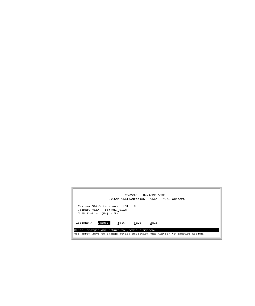
You will then see the following screen:
Figure 2-8. The Default VLAN Support Screen
2. Press [E] (for Edit), then do one or more of the following:
■ To change the maximum number of VLANs, type the new number.
■ To designate a different VLAN as the primary VLAN, select the Primary
VLAN field and use the space bar to select from the existing options.
Page 37

Port-Based Virtual LANs (Static VLANs)
■ To enable or disable dynamic VLANs, select the GVRP Enabled field and
Static Virtual LANs (VLANs)
use the Space bar to toggle between options. (For GVRP information, see
chapter 3, “GVRP”.)
Note For optimal switch memory utilization, set the number of VLANs at the
number you will likely be using or a few more. If you need more VLANs later,
you can increase this number, but a switch reboot will be required at that time.
3. Press [Enter] and then [S] to save the VLAN support configuration and
return to the VLAN Menu screen.
If you changed the value for Maximum VLANs to support, you will see an
asterisk next to the VLAN Support option (see below).
An asterisk indicates
you must reboot the
switch to implement
the new Maximum
VLANs setting.
Figure 2-9. VLAN Menu Screen Indicating the Need To Reboot the Switch
– If you changed the VLAN Support option, you must reboot the
switch before the Maximum VLANs change can take effect. You
can go on to configure other VLAN parameters first, but remember to reboot the switch when you are finished.
– If you did not change the VLAN Support option, a reboot is not
necessary.
4. Press [0] to return to the Main Menu.
2-15
Page 38

Static Virtual LANs (VLANs)
Port-Based Virtual LANs (Static VLANs)
Adding or Editing VLAN Names
Use this procedure to add a new VLAN or to edit the name of an existing VLAN.
1. From the Main Menu select:
2. Switch Configuration
If multiple VLANs are not yet configured you will see a screen similar to
figure 2-10:
8. VLAN Menu . . .
2. VLAN Names
Default VLAN
and VLAN ID
2-16
Figure 2-10. The Default VLAN Names Screen
2. Press [A] (for Add). You will then be prompted for a new VLAN name and
VLAN ID:
802.1Q VLAN ID : 1
Name : _
3. Type in a VID (VLAN ID number). This can be any number from 2 to 4094
that is not already being used by another VLAN. (The switch reserves “1”
for the default VLAN.)
Remember that a VLAN must have the same VID in every switch in which
you configure that same VLAN. (GVRP dynamically extends VLANs with
correct VID numbering to other switches. See chapter 3, “GVRP”.)
4. Press [v] to move the cursor to the Name line and type the VLAN name (up
to 12 characters, with no spaces) of a new VLAN that you want to add,
then press [Enter].
(Avoid these characters in VLAN names:
5. Press [S] (for S
ave). You will then see the VLAN Names screen with the
@, #, $, ^, &, *, (, and ).)
new VLAN listed.
Page 39
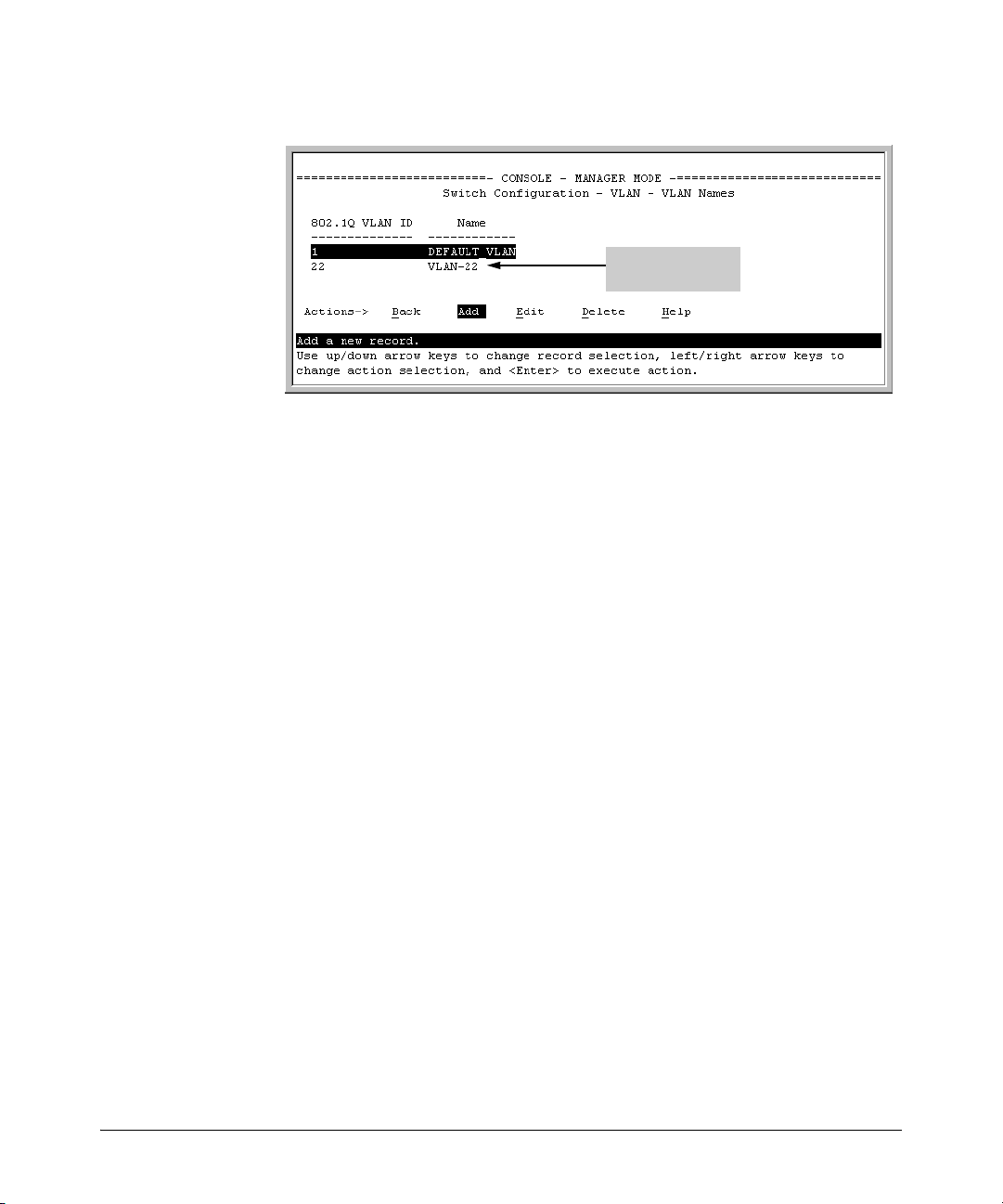
Port-Based Virtual LANs (Static VLANs)
Example of a New
VLAN and ID
Static Virtual LANs (VLANs)
Figure 2-11. Example of VLAN Names Screen with a New VLAN Added
6. Repeat steps 2 through 5 to add more VLANs.
Remember that you can add VLANs until you reach the number specified
in the Maximum VLANs to support field on the VLAN Support screen (see
figure 2-8 on page 2-14). This includes any VLANs added dynamically due
to GVRP operation.
7. Return to the VLAN Menu to assign ports to the new VLAN(s) as described
in the next section, “Adding or Changing a VLAN Port Assignment”.
Adding or Changing a VLAN Port Assignment
Use this procedure to add ports to a VLAN or to change the VLAN assignment(s) for any port. (Ports not specifically assigned to a VLAN are automatically in the default VLAN.)
1. From the Main Menu select:
2. Switch Configuration
8. VLAN Menu . . .
3. VLAN Port Assignment
You will then see a VLAN Port Assignment screen similar to the following:
2-17
Page 40

Static Virtual LANs (VLANs)
Port-Based Virtual LANs (Static VLANs)
Default: In this example,
the “VLAN-22” has been
defined, but no ports
have yet been assigned
to it. (“No” means the
port is not assigned to
that VLAN.)
Using GVRP? If you plan
on using GVRP, any
ports you don’t want to
join should be changed
to “Forbid”.
A port can be assigned
to several VLANs, but
only one of those
assignments can be
“Untagged”.
Figure 2-12. Example of VLAN Port Assignment Screen
2. To change a port’s VLAN assignment(s):
a. Press [E] (for E
dit).
b. Use the arrow keys to select a VLAN assignment you want to change.
c. Press the Space bar to make your assignment selection (No, Tagged,
Untagged, or Forbid).
Note For GVRP Operation: If you enable GVRP on the switch, “No”
converts to “Auto”, which allows the VLAN to dynamically join an
advertised VLAN that has the same VID. See “Per-Port Options for
Dynamic VLAN Advertising and Joining” on page 3-8.
Untagged VLANs: Only one untagged VLAN is allowed per port. Also,
there must be at least one VLAN assigned to each port. In the factory
default configuration, all ports are assigned to the default VLAN
(DEFAULT_VLAN).
For example, if you want ports A4 and A5 to belong to both
DEFAULT_VLAN and VLAN-22, and ports A6 and A7 to belong only to
VLAN-22, you would use the settings in figure page 2-19. (This example
assumes the default GVRP setting—disabled—and that you do not plan
to enable GVRP later.)
2-18
Page 41
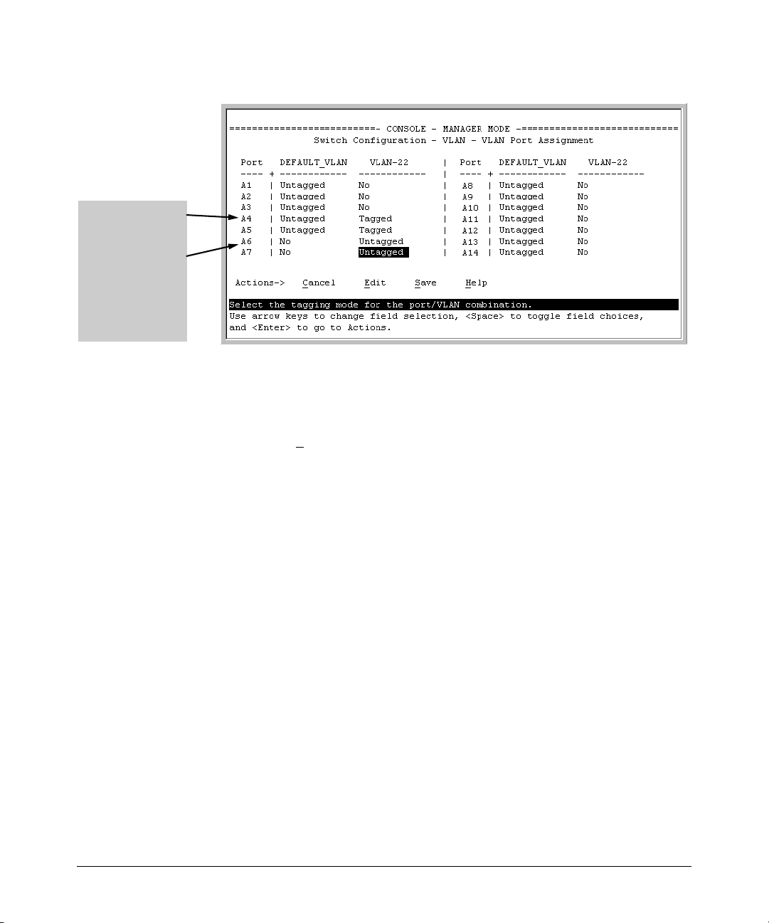
Ports A4 and A5 are
assigned to both
VLANs.
Ports A6 and A7 are
assigned only to
VLAN-22.
All other ports are
assigned only to the
Default VLAN.
Port-Based Virtual LANs (Static VLANs)
Static Virtual LANs (VLANs)
Figure 2-13. Example of VLAN Assignments for Specific Ports
For information on VLAN tags (“Untagged” and “Tagged”), refer to
“802.1Q VLAN Tagging” on page 2-26.
d. If you are finished assigning ports to VLANs, press [Enter] and then [S]
ave) to activate the changes you've made and to return to the
(for S
Configuration menu. (The console then returns to the VLAN menu.)
3. Return to the Main menu.
CLI: Configuring VLAN Parameters
In the factory default state, all ports on the switch belong to the default VLAN
(DEFAULT_VLAN) and are in the same broadcast/multicast domain. (The
default VLAN is also the default primary VLAN—see “The Primary VLAN” on
page 2-6.) You can configure additional static VLANs by adding new VLAN
names, and then assigning one or more ports to each VLAN. Note that each
port can be assigned to multiple VLANs by using VLAN tagging. (See “802.1Q
VLAN Tagging” on page 2-26.)
2-19
Page 42

Static Virtual LANs (VLANs)
Port-Based Virtual LANs (Static VLANs)
VLAN Commands Used in this Section
show vlans below
show vlan <vlan-id> page 2-21
max-vlans page 2-22
primary-vlan <vlan-id> page 2-22
[no] vlan <vlan-id> page 2-23
name <vlan-name> page 2-24
[no] tagged <port-list> page 2-24
[no] untagged <port-list> page 2-24
[no] forbid page 2-24
auto <port-list> page 2-24 (Available if GVRP enabled.)
static-vlan <vlan-id> page 2-23 (Available if GVRP enabled.)
Displaying the Switch’s VLAN Configuration. The next command lists
the VLANs currently running in the switch, with VID, VLAN name, and VLAN
status. Dynamic VLANs appear only if the switch is running with GVRP
enabled and one or more ports has dynamically joined an advertised VLAN.
(In the default configuration, GVRP is disabled. (See chapter 3, “GVRP”.)
2-20
Syntax: show vlan
When GVRP is disabled
(the default), Dynamic
VLANs do not exist on
the switch and do not
appear in this listing.
(See chapter 3,
“GVRP”.)
Figure 2-14. Example of “Show VLAN” Listing (GVRP Enabled)
Page 43

Port-Based Virtual LANs (Static VLANs)
Static Virtual LANs (VLANs)
Displaying the Configuration for a Particular VLAN. This command
uses the VID to identify and display the data for a specific static or dynamic
VLAN.
Syntax: show vlan <vlan-id>
Figure 2-15. Example of “Show VLAN” for a Specific Static VLAN
Show VLAN lists this
data when GVRP is
enabled and at least
one port on the switch
has dynamically
joined the designated
VLAN.
Figure 2-16. Example of “Show VLAN” for a Specific Dynamic VLAN
2-21
Page 44
Static Virtual LANs (VLANs)
Port-Based Virtual LANs (Static VLANs)
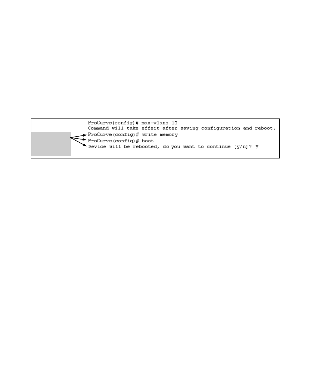
Changing the Number of VLANs Allowed on the Switch. By default,
the switch allows a maximum of 8 VLANs. You can specify any value from 1
to the upper limit for the switch. If GVRP is enabled, this setting includes any
dynamic VLANs on the switch. As part of implementing a new value, you must
execute a write memory command (to save the new value to the startup-config
file) and then reboot the switch.
Syntax: max-vlans <1... 256>
For example, to reconfigure the switch to allow 10 VLANs:
Note that you can
execute these
three steps at
another time.
Figure 2-17. Example of Command Sequence for Changing the Number of VLANs
Changing the Primary VLAN. In the factory-default configuration, the
default VLAN (DEFAULT_VLAN) is the primary VLAN. However, you can
designate any static VLAN on the switch as the primary VLAN. (For more on
the primary VLAN, see “The Primary VLAN” on page 2-6.) To view the available
VLANs and their respective VIDs, use show vlan.
2-22
Syntax: primary-vlan <vlan-id>
For example, to make VLAN 22 the primary VLAN:
ProCurve(config)# primary-vlan 22
Page 45

Port-Based Virtual LANs (Static VLANs)
Static Virtual LANs (VLANs)
Creating a New Static VLAN
Changing the VLAN Context Level.
With this command, entering a new VID creates a new static VLAN. Entering
the VID or name of an existing static VLAN places you in the context level for
that VLAN.
Syntax: vlan <vlan-id> [name <name-str>]
Creates a new static VLAN if a VLAN with that VID does not
already exist, and places you in that VLAN’s context level. If
you do not use the name option, the switch uses “VLAN” and
the new VID to automatically name the VLAN. If the VLAN
already exists, the switch places you in the context level for
that VLAN.
vlan <vlan-name>
Places you in the context level for that static VLAN.
For example, to create a new static VLAN with a VID of 100:
Creating the new VLAN.
Showing the result.
Figure 2-18. Example of Creating a New Static VLAN
To go to a different VLAN context level, such as to the default VLAN:
ProCurve(vlan-100)# vlan default_vlan
ProCurve(vlan-1) _
Converting a Dynamic VLAN to a Static VLAN. If GVRP is running on
the switch and a port dynamically joins a VLAN, you can use the next
command to convert the dynamic VLAN to a static VLAN. (For GVRP and
dynamic VLAN operation, see chapter 3, “GVRP”.) This is necessary if you
2-23
Page 46

Static Virtual LANs (VLANs)
Port-Based Virtual LANs (Static VLANs)
want to make the VLAN permanent. After you convert a dynamic VLAN to
static, you must configure the switch’s per-port participation in the VLAN in
the same way that you would for any static VLAN.
Syntax: static-vlan <vlan-id>(Use show vlan to list current VIDs.)
For example, suppose a dynamic VLAN with a VID of 125 exists on the switch.
The following command converts the VLAN to a static VLAN.
ProCurve(config)# static-vlan 125
Configuring Static VLAN Name and Per-Port Settings. The vlan <vlan-
id> command, used with the options listed below, changes the name of an
existing static VLAN and changes the per-port VLAN membership settings.
Note You can use these options from the configuration level by beginning the
command with vlan <vlan-id>, or from the context level of the specific VLAN.
Syntax: name <vlan-name>
Changes the name of the existing static VLAN. (Avoid
spaces and the following characters in the <vlan-name>
entry: 2, #, $, ^, &, *, (, and ).)
[no] tagged <port-list>
Configures the indicated port(s) as Tagged for the specified
VLAN. The “no” version sets the port(s) to either No or (if
GVRP is enabled) to Auto.
2-24
[no] untagged <port-list>
Configures the indicated port(s) as Untagged for the
specified VLAN. The “no” version sets the port(s) to either
No or (if GVRP is enabled) to Auto.
[no] forbid <port-list>
Configures the indicated port(s) as “forbidden” to
participate in the designated VLAN. The “no” version sets
the port(s) to either No or (if GVRP is enabled) to Auto.
auto <port-list>
Available if GVRP is enabled on the switch. Returns the
per-port settings for the specified VLAN to Auto operation.
Note that Auto is the default per-port setting for a static
VLAN if GVRP is running on the switch. (For information
on dynamic VLAN and GVRP operation, see
chapter 3, “GVRP”.)
Page 47

Port-Based Virtual LANs (Static VLANs)
Static Virtual LANs (VLANs)
For example, if you have a VLAN named VLAN100 with a VID of 100, and all
ports are set to No for this VLAN. To change the VLAN name to “Blue_Team”
and set ports 1-5 to Tagged, you could do so with these commands:
ProCurve(config)# vlan 100 name Blue_Team
ProCurve(config)# vlan 100 tagged 1-5
To move to the vlan 100 context level and execute the same commands:
ProCurve(config)# vlan 100
ProCurve(vlan-100)# name Blue_Team
ProCurve(vlan-100)# tagged 1-5
Similarly, to change the tagged ports in the above examples to No (or Auto, if
GVRP is enabled), you could use either of the following commands.
At the config level, use:
ProCurve(config)# no vlan 100 tagged 1-5
- or -
At the VLAN 100 context level, use:
ProCurve(vlan-100)# no tagged 1-5
Note You cannot use these commands with dynamic VLANs. Attempting to do so
results in the message “VLAN already exists.” and no change occurs.
Web: Viewing and Configuring VLAN Parameters
In the web browser interface you can do the following:
■ Add VLANs
■ Rename VLANs
■ Remove VLANs
■ Configure GVRP mode
■ Select a new Primary VLAN
To configure static VLAN port parameters, you will need to use the menu
interface (available by Telnet from the web browser interface) or the CLI.
1. Click on the Configuration tab.
2. Click on VLAN Configuration.
3. Click on Add/Remove VLANs.
For web-based Help on how to use the web browser interface screen, click on
the
[?] button provided on the web browser screen.
2-25
Page 48
Static Virtual LANs (VLANs)
Port-Based Virtual LANs (Static VLANs)
802.1Q VLAN Tagging
VLAN tagging enables traffic from more than one VLAN to use the same port.
(Even when two or more VLANs use the same port they remain as separate
domains and cannot receive traffic from each other without going through an
external router.) As mentioned earlier, a “tag” is simply a unique VLAN
identification number (VLAN ID, or VID) assigned to a VLAN at the time that
you configure the VLAN name in the switch. The tag can be any number from
1 to 4094 that is not already assigned to a VLAN. When you subsequently assign
a port to a given VLAN, you must implement the VLAN tag (VID) if the port
will carry traffic for more than one VLAN. Otherwise, the port VLAN assignment can remain “untagged” because the tag is not needed. On a given switch,
this means you should use the “Untagged” designation for a port VLAN
assignment where the port is connected to non 802.1Q-compliant device or is
assigned to only one VLAN. Use the “Tagged” designation when the port is
assigned to more than one VLAN or the port is connected to a device that does
comply with the 802.1Q standard.
For example, if port A7 on an 802.1Q-compliant switch is assigned to only the
Red VLAN, the assignment can remain “untagged” because the port will
forward traffic only for the Red VLAN. However, if both the Red and Green
VLANs are assigned to port A7, then at least one of those VLAN assignments
must be “tagged” so that Red VLAN traffic can be distinguished from Green
VLAN traffic. The following illustration shows this concept:
2-26
Server
Red
VLAN
Red
Server
Green
Server
Ports 1-6: Untagged
Port 7: Red VLAN Untagged
Blue
Blue
VLAN
6
5
4
Switch
7
"X"
3
1
2
Green
VLAN
Green VLAN Tagged
White
Server
Red VLAN: Untagged
Green VLAN: Tagged
VLAN
Ports 1-4: Untagged
Port 5: Red VLAN Untagged
White
VLAN
4
3
Switch
5
"Y"
1
2
Green
Red
VLAN
Green VLAN Tagged
Figure 2-19. Example of Tagged and Untagged VLAN Port Assignments
Page 49

Port-Based Virtual LANs (Static VLANs)
■ In switch X:
Static Virtual LANs (VLANs)
• VLANs assigned to ports X1 - X6 can all be untagged because there is
only one VLAN assignment per port. Red VLAN traffic will go out only
the Red ports; Green VLAN traffic will go out only the Green ports,
and so on. Devices connected to these ports do not have to be 802.1Qcompliant.
• However, because both the Red VLAN and the Green VLAN are
assigned to port X7, at least one of the VLANs must be tagged for this
port.
■ In switch Y:
• VLANs assigned to ports Y1 - Y4 can all be untagged because there is
only one VLAN assignment per port. Devices connected to these ports
do not have to be 802.1Q-compliant.
• Because both the Red VLAN and the Green VLAN are assigned to port
Y5, at least one of the VLANs must be tagged for this port.
■ In both switches: The ports on the link between the two switches must be
configured the same. As shown in figure 2-19 (above), the Red VLAN must
be untagged on port X7 and Y5 and the Green VLAN must be tagged on
port X7 and Y5, or vice-versa.
Note Each 802.1Q-compliant VLAN must have its own unique VID number, and that
VLAN must be given the same VID in every device in which it is configured.
That is, if the Red VLAN has a VID of 10 in switch X, then 10 must also be used
for the Red VID in switch Y.
VID Numbers
Figure 2-20. Example of VLAN ID Numbers Assigned in the VLAN Names Screen
2-27
Page 50

Static Virtual LANs (VLANs)
Port-Based Virtual LANs (Static VLANs)
VLAN tagging gives you several options:
■ Since the purpose of VLAN tagging is to allow multiple VLANs on the same
port, any port that has only one VLAN assigned to it can be configured as
“Untagged” (the default).
■ Any port that has two or more VLANs assigned to it can have one VLAN
assignment for that port as “Untagged”. All other VLANs assigned to the
same port must be configured as “Tagged”. (There can be no more than
one Untagged VLAN on a port.)
■ If all end nodes on a port comply with the 802.1Q standard and are
configured to use the correct VID, then, you can configure all VLAN
assignments on a port as “Tagged” if doing so makes it easier to manage
your VLAN assignments, or for security reasons.
For example, in the following network, switches X and Y and servers S1 and
S2 are 802.1Q-compliant. (Server S3 could also be 802.1Q-compliant, but it
makes no difference for this example.)
Red
VLAN
Server
S2
Y1
Switch
Y4
"Y"
Y2Y5
Y3
Green
VLAN
Green VLAN only
Server
S3
Server
S1
Red VLAN: Untagged Red VLAN: Untagged
Green VLAN: Tagged Green VLAN: Tagged
X1
Switch
"X"
X4
Red
VLAN
X2
X3
Green
VLAN
Red VLAN: Untagged
Green VLAN: Tagged
Figure 2-21. Example of Networked 802.1Q-Compliant Devices with Multiple
VLANs on Some Ports
2-28
Page 51

Port-Based Virtual LANs (Static VLANs)
Static Virtual LANs (VLANs)
The VLANs assigned to ports X3, X4, Y2, Y3, and Y4 can all be untagged
because there is only one VLAN assigned per port. Port X1 has multiple VLANs
assigned, which means that one VLAN assigned to this port can be untagged
and any others must be tagged. The same applies to ports X2, Y1, and Y5.
Switch X Switch Y
Port Red VLAN Green VLAN Port Red VLAN Green VLAN
X1 Untagged Tagged Y1 Untagged Tagged
X2 Untagged Tagged
X3 No* Untagged Y3 No* Untagged
X4 Untagged No*
*”No” means the port is not a member of that VLAN. For example, port X3 is not
a member of the Red VLAN and does not carry Red VLAN traffic. Also, if GVRP
were enabled, “Auto” would appear instead of “No”.
Y2 No* Untagged
Y4 Untagged No*
Y5 Untagged Tagged
Note VLAN configurations on ports connected by the same link must match.
Because ports X2 and Y5 are opposite ends of the same point-to-point connection, both ports must have the same VLAN configuration; that is, both ports
configure the Red VLAN as “Untagged” and the Green VLAN as “Tagged”.
To summarize:
VLANs Per
Port
1 Untagged or Tagged. If the device connected to the port is 802.1Q-compliant,
2 or More 1 VLAN Untagged; all others Tagged
Tagging Scheme
then the recommended choice is “Tagged”.
or
All VLANs Tagged
A given VLAN must have the same VID on any 802.1Q-compliant device in which the VLAN is
configured.
The ports connecting two 802.1Q devices should have identical VLAN configurations, as
shown for ports X2 and Y5, above.
2-29
Page 52

Static Virtual LANs (VLANs)
Port-Based Virtual LANs (Static VLANs)
The Secure Management VLAN
Configures a secure Management VLAN by creating an isolated network for
managing the following ProCurve switches that support this feature:
• Series 2600 switches
• Series 2600-PWR switches
• Series 2800 switches
• Switch 2810
• Series 3400cl switches
• Series 4200vl switches
• Series 5300xl switches
• Series 5400zl switches
• Switch 6108
• Series 6400cl switches
• Series 4100gl switches
Access to this VLAN, and to the switch’s management functions (Menu, CLI,
and web browser interface) is available only through ports configured as
members.
■ Multiple ports on the switch can belong to the Management VLAN. This
allows connections for multiple management stations you want to have
access to the Management VLAN, while at the same time allowing Management VLAN links between switches configured for the same Management VLAN.
■ Only traffic from the Management VLAN can manage the switch, which
means that only the workstations and PCs connected to ports belonging
to the Management VLAN can manage and reconfigure the switch.
Figure 2-22 illustrates use of the Management VLAN feature to support management access by a group of management workstations.
2-30
Page 53

Port-Based Virtual LANs (Static VLANs)
Static Virtual LANs (VLANs)
• Switches “A”, “B”, and
“C” are connected by
Switch A
ports belonging to the
management VLAN.
• Hub “X” is connected
to a switch port that
belongs to the
Hub Y
management VLAN. As
a result, the devices
connected to Hub X are
included in the
management VLAN.
• Other devices
connected to the
switches through ports
that are not in the
management VLAN are
excluded from
management traffic.
Links with Ports Belonging to the Management VLAN and other VLANs
Links Between Ports on a Hub and Ports belonging to the Management VLAN
Links Not Belonging to the Management VLAN
Links to Other Devices
Figure 2-22. Example of Potential Security Breaches
In figure 2-23, Workstation 1 has management access to all three switches
through the Management VLAN, while the PCs do not. This is because configuring a switch to recognize a Management VLAN automatically excludes
attempts to send management traffic from any other VLAN.
Hub X
Management Workstations
Switch B
Server
Switch C
Links with Ports
Configured as Members of
the Management VLAN
and other VLANs
Links Not Belonging to the
Management VLAN
System
Management
Workstation
Port A1
Port A3
Port A6
Port A7
Switch
A
1
Shipping
Switch
B
Port B2
Port B4
Port B5
Port B9
2
Server
Switch
C
Port C2
Port C3
Port C6
Port C8
Server
System Server
(on the
DEFAULT_VLAN)
3
4
Server
Marketing
2-31
Page 54

Static Virtual LANs (VLANs)
Port-Based Virtual LANs (Static VLANs)
Figure 2-23. Example of Management VLAN Control in a LAN
Table 2-2. VLAN Membership in Figure 2-23
Switch A1 A3 A6 A7 B2 B4 B5 B9 C2 C3 C6 C8
Management VLAN (VID = 7) Y NNYYYNNY NNN
Marketing VLAN (VID = 12) NNNNNNNNNYYY
Shipping Dept. VLAN (VID = 20) N YYNNNNNNNNN
DEFAULT-VLAN (VID = 1) YYYYYYYYYYYY
Preparation
1. Determine a VID and VLAN name suitable for your Management VLAN.
2. Determine the IP addressing for the Management VLAN (DHCP/Bootp or
Manual.
3. Plan your Management VLAN topology to use ProCurve switches that
support this feature. (See the list on page 2-30.) The ports belonging to the
Management VLAN should be only the following:
• Ports to which you will connect authorized management stations
(such as Port A7 in figure 2-23.)
• Ports on one switch that you will use to extend the Management VLAN
to ports on other ProCurve switches (such as ports A1 and B2 or B4
and C2 in figure 2-23 on page 2-32.).
Hubs dedicated to connecting management stations to the Management VLAN
can also be included in the above topology. Note that any device connected
to a hub in the Management VLAN will also have Management VLAN access.
4. Configure the Management VLAN on the selected switch ports.
5. Test the management VLAN from all of the management stations authorized to use the Management VLAN, including any SNMP-based network
management stations. Ensure that you include testing any Management
VLAN links between switches.
Note If you configure a Management VLAN on a switch by using a Telnet connection
through a port that is not in the Management VLAN, then you will lose
management contact with the switch if you log off your Telnet connection or
execute write memory and reboot the switch.
2-32
Page 55
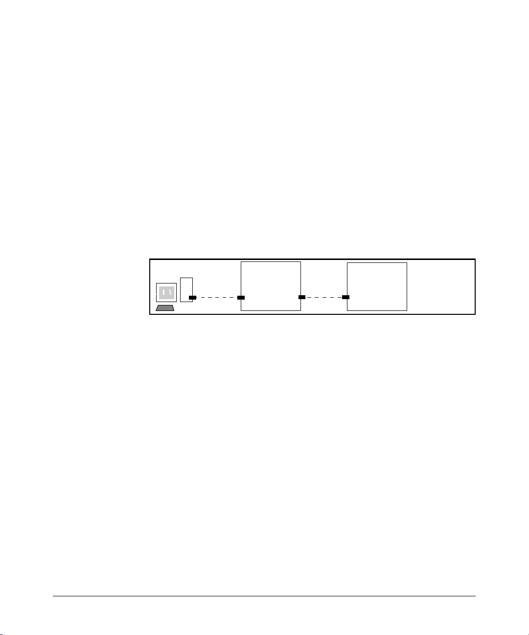
Port-Based Virtual LANs (Static VLANs)
Static Virtual LANs (VLANs)
Configuration
Syntax: [ no ] management-vlan < vlan-id | vlan-name >
Default: Disabled
To confirm the Management VLAN configuration, use the
show running-config command.
For example, suppose you have already configured a VLAN named My_VLAN
with a VID of 100. Now you want to configure the switch to do the following:
■ Use My_VLAN as a Management VLAN (tagged, in this case) to connect
port A1 on switch “A” to a management station. (The management station
includes a network interface card with 802.1Q tagged VLAN capability.)
■ Use port A2 to extend the Management VLAN to port B1 (which is already
configured as a tagged member of My_VLAN) on an adjacent switch.
ProCurve
Switch
A1
“A”
A2
ProCurve
B1
Switch
B”
“
Figure 2-24. Illustration of Configuration Example
ProCurve(config)# management-vlan 100
ProCurve(config)# vlan 100 tagged a1
ProCurve(config)# vlan 100 tagged a2
Deleting the Management VLAN. You can disable the Secure Management feature without deleting the VLAN itself. For example, either of the
following commands disables the Secure Management feature in the above
example:
ProCurve(config)# no management-vlan 100
ProCurve(config)# no management-vlan my_vlan
Operating Notes for Management VLANs
■ Only one Management-VLAN can be active in the switch. If one Manage-
ment-VLAN VID is saved in the startup-config file and you configure a
different VID in the running-config file, the switch uses the running-config
version until you either use the write-memory command or reboot the
switch.
2-33
Page 56
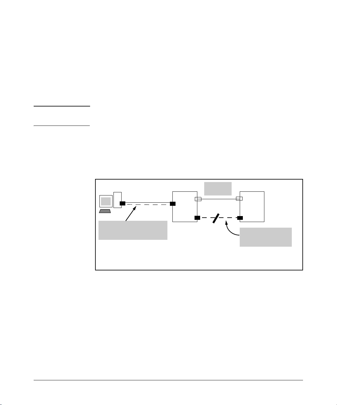
Static Virtual LANs (VLANs)
Port-Based Virtual LANs (Static VLANs)
■ During a Telnet session to the switch, if you configure the Management-
VLAN to a VID that excludes the port through which you are connected
to the switch, you will continue to have access only until you terminate
the session by logging out or rebooting the switch.
■ During a web browser session to the switch, if you configure the Manage-
ment-VLAN to a VID that excludes the port through which you are
connected to the switch, you will continue to have access only until you
close the browser session or rebooting the switch.
Note The Management-VLAN feature does not control management access through
a direct connection to the switch’s serial port.
■ Enabling Spanning Tree where there are multiple links using separate
VLANs, including the Management VLAN, between a pair of switches,
Spanning Tree will force the blocking of one or more links. This may
include the link carrying the Management VLAN, which will cause loss of
management access to some devices.
VLAN 1
Switch
1
VLAN 40
Switch
2
2-34
VLAN 20 (Management VLAN)
VLAN 1
VLAN 40
Even though the ports on the Management VLAN link between Switch 1 and Switch 2 do not belong
to the other VLANs connecting the two switches, enabling Spanning Tree will block one of the two
links. This is because Spanning Tree operates per-switch and not per-VLAN.
VLAN 20 Only
(Management VLAN)
Blocked
Figure 2-25. Example of Inadvertently Blocking a Management VLAN Link by
Implementing Spanning Tree
Effect of VLANs on Other Switch Features
Spanning Tree Operation with VLANs
Because the switch follows the 802.1Q VLAN recommendation to use singleinstance spanning tree, Spanning Tree operates across all ports on the switch
(regardless of VLAN assignments) instead of on a per-VLAN basis. This means
that if redundant physical links exist between the switch and another 802.1Q
device, all but one link will be blocked, regardless of whether the redundant
Page 57

Port-Based Virtual LANs (Static VLANs)
Static Virtual LANs (VLANs)
links are in separate VLANs. However, you can use port trunking to prevent
Spanning Tree from unnecessarily blocking ports (and to improve overall
network performance).
Note that Spanning Tree operates differently in different devices. For example, in the (obsolete, non-802.1Q) ProCurve Switch 2000 and the ProCurve
Switch 800T, Spanning Tree operates on a per-VLAN basis, allowing redundant
physical links as long as they are in separate VLANs.
IP Interfaces
There is a one-to-one relationship between a VLAN and an IP network interface. Since the VLAN is defined by a group of ports, the state (up/down) of
those ports determines the state of the IP network interface associated with
that VLAN. When a VLAN comes up because one or more of its ports is up, the
IP interface for that VLAN is also activated. Likewise, when a VLAN is
deactivated because all of its ports are down, the corresponding IP interface
is also deactivated.
VLAN MAC Addresses
Some switch models use the same MAC address for all configured VLANs,
while other switch models use a different MAC address for each configured
VLAN.
One (Same) MAC Address for all VLANs Different MAC Address for Each VLAN
2600
2600-PWR
2810
2800
3400cl
5300xl
6400cl
4100gl
6108
You can send an 802.2 test packet to the VLAN MAC address to verify
connectivity to the switch. Likewise, you can assign an IP address to the VLAN
interface, and when you Ping that address, ARP will resolve the IP address to
this MAC address.
Port Trunks
When assigning a port trunk to a VLAN, all ports in the trunk are automatically
assigned to the same VLAN. You cannot split trunk members across multiple
VLANs. Also, a port trunk is tagged, untagged, or excluded from a VLAN in the
same way as for individual, untrunked ports.
2-35
Page 58

Static Virtual LANs (VLANs)
Port-Based Virtual LANs (Static VLANs)
Port Monitoring
If you designate a port on the switch for network monitoring, this port will
appear in the Port VLAN Assignment screen and can be configured as a
member of any VLAN. For information on how broadcast, multicast, and
unicast packets are tagged inside and outside of the VLAN to which the
monitor port is assigned, see the appendix on troubleshooting in the Manage-
ment and Configuration Guide.
VLAN Restrictions
■ A port must be a member of at least one VLAN. In the factory default
configuration, all ports are assigned to the default VLAN
(DEFAULT_VLAN; VID = 1).
■ A port can be assigned to several VLANs, but only one of those assign-
ments can be untagged. (The “Untagged” designation enables VLAN operation with non 802.1Q-compliant devices.)
■ An external router must be used to communicate between tagged VLANs
on the switch.
■ Before you can delete a VLAN, you must first re-assign all ports in the
VLAN to another VLAN.
2-36
Jumbo Packet Support
Jumbo packet support is enabled per-VLAN and applies to all ports belonging
to the VLAN. For more information, refer to the chapter titled “Port Status and
Basic Configuration” in the Management and Configuration Guide for your
switch.
Page 59

GVRP
3
Contents
Overview . . . . . . . . . . . . . . . . . . . . . . . . . . . . . . . . . . . . . . . . . . . . . . . . . . . . . . 3-2
Introduction . . . . . . . . . . . . . . . . . . . . . . . . . . . . . . . . . . . . . . . . . . . . . . . . . . . 3-3
General Operation . . . . . . . . . . . . . . . . . . . . . . . . . . . . . . . . . . . . . . . . . . . 3-4
Per-Port Options for Handling GVRP “Unknown VLANs” . . . . . . . . . . 3-6
Per-Port Options for Dynamic VLAN Advertising and Joining . . . . . . 3-8
GVRP and VLAN Access Control . . . . . . . . . . . . . . . . . . . . . . . . . . . . . . 3-10
Port-Leave From a Dynamic VLAN . . . . . . . . . . . . . . . . . . . . . . . . 3-10
Planning for GVRP Operation . . . . . . . . . . . . . . . . . . . . . . . . . . . . . . . . 3-10
Configuring GVRP On a Switch . . . . . . . . . . . . . . . . . . . . . . . . . . . . . . . 3-11
Menu: Viewing and Configuring GVRP . . . . . . . . . . . . . . . . . . . . . 3-12
CLI: Viewing and Configuring GVRP . . . . . . . . . . . . . . . . . . . . . . . 3-13
Web: Viewing and Configuring GVRP . . . . . . . . . . . . . . . . . . . . . . 3-16
GVRP Operating Notes . . . . . . . . . . . . . . . . . . . . . . . . . . . . . . . . . . . . . . 3-17
3-1
Page 60

GVRP
Overview
Overview
This chapter describes GVRP and how to configure it with the switch’s builtin interfaces, and assumes an understanding of VLANs, which are described
in Chapter 2, “Static Virtual LANs (VLANs)”.
For general information on how to use the switch’s built-in interfaces, refer to
these chapters in the Management and Configuration Guide for your switch:
■ Chapter 3, “Using the Menu Interface”
■ Chapter 4, “Using the Command Line Interface (CLI)”
■ Chapter 5, “Using the Web Browser Interface”
■ Chapter 6, “Switch Memory and Configuration”
3-2
Page 61

GVRP
Introduction
Introduction
Feature Default Menu CLI Web
view GVRP configuration n/a page 3-12 page 3-13 page 3-16
list static and dynamic VLANs
on a GVRP-enabled switch
enable or disable GVRP disabled page 3-12 page 3-14 page 3-16
enable or disable GVRP on
individual ports
control how individual ports
will handle advertisements for
new VLANs
convert a dynamic VLAN to a
static VLAN
configure static VLANs DEFAULT_VLAN
GVRP—GARP VLAN Registration Protocol—is an application of the Generic
Attribute Registration Protocol—GARP. GVRP is defined in the IEEE 802.1Q
standard, and GARP is defined in the IEEE 802.1D-1998 standard.
n/a — page 3-15 page 3-16
enabled page 3-12 page 3-14 —
Learn page 3-12 page 3-14 page 3-16
n/a — page 3-16 —
page 2-14 page 2-19 page 2-25
(VID = 1)
Note To understand and use GVRP you must have a working knowledge of 802.1Q
VLAN tagging. (See “Port-Based Virtual LANs (Static VLANs)” on page 2-3.)
GVRP uses “GVRP Bridge Protocol Data Units” (“GVRP BPDUs”) to “advertise” static VLANs. In this manual, a GVRP BPDU is termed an advertisement.
Advertisements are sent outbound from ports on a switch to the devices
directly connected to those ports.
GVRP enables the switch to dynamically create 802.1Q-compliant VLANs on
links with other devices running GVRP. This enables the switch to automatically create VLAN links between GVRP-aware devices. (A GVRP link can
include intermediate devices that are not GVRP-aware.) This operation
reduces the chances for errors in VLAN configuration by automatically providing VLAN ID (VID) consistency across the network. That is, you can use
GVRP to propagate VLANs to other GVRP-aware devices instead of manually
having to set up VLANs across your network. After the switch creates a
dynamic VLAN, you can optionally use the CLI static <vlan-id> command to
convert it to a static VLAN or allow it to continue as a dynamic VLAN for as
long as needed. You can also use GVRP to dynamically enable port membership in static VLANs configured on a switch.
3-3
Page 62

GVRP
Introduction
General Operation
When GVRP is enabled on a switch, the VID for any static VLANs configured
on the switch is advertised (using BPDUs—Bridge Protocol Data Units) out
all ports, regardless of whether a port is up or assigned to any particular VLAN.
A GVRP-aware port on another device that receives the advertisements over
a link can dynamically join the advertised VLAN.
A dynamic VLAN (that is, a VLAN learned through GVRP) is tagged on the port
on which it was learned. Also, a GVRP-enabled port can forward an advertisement for a VLAN it learned about from other ports on the same switch (internal
source), but the forwarding port will not itself join that VLAN until an advertisement for that VLAN is received through a link from another device (external source) on that specific port
Operating Note: When a GVRP-aware port on a switch learns a VID through GVRP from another device, the switch begins
advertising that VID out all of its ports except the port on which the VID was learned.
Core switch with static
VLANs (VID= 1, 2, & 3). Port 2
is a member of VIDs 1, 2, & 3.
1. Port 2 advertises VIDs 1, 2,
& 3.
2. Port 1 receives advertise-
ment of VIDs 1, 2, & 3 AND
becomes a member of VIDs
1, 2, & 3.
3. Port 3 advertises VIDs 1, 2,
& 3, but port 3 is NOT a
member of VIDs 1, 2, & 3 at
this point.
4. Port 4 receives advertise-
ment of VIDs 1, 2, & 3 AND
becomes a member of VIDs
1, 2, & 3.
5. Port 5 advertises VIDs 1, 2,
& 3, but port 5 is NOT a
member of VIDs 1, 2, & 3 at
this point.
Port 6 is statically configured
to be a member of VID 3.
Switch 1
GVRP On
2
11. Port 2 receives
advertisement of VID 3. (Port
2 is already statically
configured for VID 3.)
Switch 2
GVRP On
1
3
9. Port 3 receives advertise-
ment of VID 3 AND becomes
a member of VID 3. (Still not
a member of VIDs 1 & 2.)
10. Port 1 advertises VID 3.
Switch 3
GVRP On
4
5
7. Port 5 receives advertise-
ment of VID 3 AND becomes
a member of VID 3. (Still not
a member of VIDs 1 & 2.)
8. Port 4 advertises VID 3.
Figure 3-1. Example of Forwarding Advertisements and Dynamic Joining
3-4
Static VLAN configured End Device
(NIC or switch) with
GVRP On
6
6. Port 6 advertises VID 3.
Page 63

GVRP
Introduction
Note that if a static VLAN is configured on at least one port of a switch, and
that port has established a link with another device, then all other ports of that
switch will send advertisements for that VLAN.
For example, in the following figure, Tagged VLAN ports on switch “A” and
switch “C” advertise VLANs 22 and 33 to ports on other GVRP-enabled
switches that can dynamically join the VLANs.
5
Switch “C”
GVRP On
Tagged
VLAN 33
Switch “D”
GVRP On
Switch “C”:
Port 5 dynamically joins VLAN 22.
Ports 11 and 12 belong to Tagged VLAN 33.
11
Switch “E”
2
12
3
6
Switch “E”:
Port 2 dynamically joins VLANs 22 and 33.
Port 7 dynamically joins VLANs 33 and 22.
GVRP On
7
Switch “A”
GVRP On
1
Tagged
VLAN 22
Switch “B”
(No GVRP)
Tagged
VLAN 22
Switch “D”:
Port 3 dynamically joins VLANs 22 and 33.
Port 6 dynamically joins VLAN 22 and 33.
Figure 3-2. Example of GVRP Operation
Note A port can learn of a dynamic VLAN through devices that are not aware of
GVRP (Switch “B”, above). VLANs must be disabled in GVRP-unaware devices
to allow tagged packets to pass through.
A GVRP-aware port receiving advertisements has these options:
■ If there is not already a static VLAN with the advertised VID on the
receiving port, then dynamically create the VLAN and become a member.
3-5
Page 64

GVRP
Introduction
■ If the switch already has a static VLAN assignment with the same VID as
in the advertisement, and the port is configured to Auto for that VLAN,
then the port will dynamically join the VLAN and begin moving that
VLAN’s traffic. (For more detail on Auto, see “Per-Port Options for
Dynamic VLAN Advertising and Joining” on page 3-8.)
■ Ignore the advertisement for that VID.
■ Don’t participate in that VLAN.
Note also that a port belonging to a Tagged or Untagged static VLAN has these
configurable options:
■ Send VLAN advertisements, and also receive advertisements for VLANs
on other ports and dynamically join those VLANs.
■ Send VLAN advertisements, but ignore advertisements received from
other ports.
■ Avoid GVRP participation by not sending advertisements and dropping
any advertisements received from other devices.
IP Addressing. A dynamic VLAN does not have an IP address, and moves
traffic on the basis of port membership in VLANs. However, after GVRP
creates a dynamic VLAN, you can convert it to a static VLAN. Note that it is
then necessary to assign ports to the VLAN in the same way that you would
for a static VLAN that you created manually. In the static state you can
configure IP addressing on the VLAN and access it in the same way that you
would any other static (manually created) VLAN.
3-6
Per-Port Options for Handling GVRP “Unknown VLANs”
An “unknown VLAN” is a VLAN that the switch learns of by receiving an
advertisement for that VLAN on a port that is not already a member of that
VLAN. If the port is configured to learn unknown VLANs, then the VLAN is
dynamically created and the port becomes a tagged member of the VLAN. For
example, suppose that in figure 3-2 (page 3-5), port 1 on switch “A” is connected to port 5 on switch “C”. Because switch “A” has VLAN 22 statically
configured, while switch “C” does not have this VLAN statically configured
(and does not “Forbid” VLAN 22 on port 5), VLAN 22 is handled as an
“Unknown VLAN” on port 5 in switch “C”. Conversely, if VLAN 22 was
statically configured on switch C, but port 5 was not a member, port 5 would
become a member when advertisements for VLAN 22 were received from
switch “A”.
When you enable GVRP on a switch, you have the per-port join-request options
listed in Table 3-1.
Page 65

Table 3-1. Options for Handling “Unknown VLAN” Advertisements:
GVRP
Introduction
Unknown VLAN
Mode
Learn
(the Default)
Block Prevents the port from joining any new dynamic VLANs for which it receives
Disable Causes the port to ignore and drop all GVRP advertisements it receives and
Operation
Enables the port to become a member of any unknown VLAN for which it
receives an advertisement. Allows the port to advertise other VLANs that
have at least one other port on the same switch as a member.
an advertisement.
Allows the port to advertise other VLANs that have at least one other port
as a member.
also prevents the port from sending any GVRP advertisements.
The CLI show gvrp command and the menu interface VLAN Support screen
show a switch’s current GVRP configuration, including the Unknown VLAN
settings.
GVRP Enabled
(Required for Unknown
VLAN operation.)
Unknown VLAN Settings
Learn
Default:
Figure 3-3. Example of GVRP Unknown VLAN Settings
3-7
Page 66

GVRP
Introduction
Per-Port Options for Dynamic VLAN Advertising and Joining
Initiating Advertisements. As described in the preceding section, to
enable dynamic joins, GVRP must be enabled and a port must be configured
to Learn (the default). However, to send advertisements in your network, one
or more static (Tagged, Untagged, or Auto) VLANs must be configured on one
or more switches (with GVRP enabled), depending on your topology.
Enabling a Port for Dynamic Joins. You can configure a port to dynamically join a static VLAN. The join will then occur if that port subsequently
receives an advertisement for the static VLAN. (This is done by using the Auto
and Learn options described in table 3-2, below.
Parameters for Controlling VLAN Propagation Behavior. You can configure an individual port to actively or passively participate in dynamic VLAN
propagation or to ignore dynamic VLAN (GVRP) operation. These options are
controlled by the GVRP “Unknown VLAN” and the static VLAN configuration
parameters, as described in the following table:
Table 3-2. Controlling VLAN Behavior on Ports with Static VLANs
Per-Port
“Unknown
VLAN”
(GVRP)
Configuration
Port Activity:
Tagged or Untagged (Per VLAN)
Static VLAN Options—Per VLAN Specified on Each Port
Port Activity:
2
2
Auto
(Per VLAN)
1
Port Activity: Forbid (Per VLAN)
2
Learn
(the Default)
3-8
The port:
• Belongs to specified VLAN.
• Advertises specified VLAN.
• Can become a member of
dynamic VLANs for which it
receives advertisements.
• Advertises dynamic VLANs
that have at least one other
port (on the same switch) as a
member.
The port:
• Will become a member of
specified VLAN if it receives
advertisements for specified
VLAN from another device.
• Will advertise specified VLAN.
• Can become a member of
other, dynamic VLANs for
which it receives
advertisements.
• Will advertise a dynamic VLAN
that has at least one other port
(on the same switch) as a
member.
The port:
1. Will not become a member of
the specified VLAN.
1. Will not advertise specified
VLAN.
1. Can become a member of
other dynamic VLANs for
which it receives
advertisements.
1. Will advertise a dynamic VLAN
that has at least one other port
on the same switch as a
member.
Page 67

GVRP
Introduction
Per-Port
Static VLAN Options—Per VLAN Specified on Each Port
1
“Unknown
VLAN”
(GVRP)
Configuration
Block The port:
Port Activity:
Tagged or Untagged (Per VLAN)
• Belongs to the specified VLAN.
• Advertises this VLAN.
• Will not become a member of
new dynamic VLANs for which
it receives advertisements.
• Will advertise dynamic VLANs
that have at least one other
port as a member.
Port Activity:
2
2
Auto
(Per VLAN)
The port:
• Will become a member of
specified VLAN if it receives
advertisements for this VLAN.
• Will advertise this VLAN.
• Will not become a member of
new dynamic VLANs for which
it receives advertisements.
• Will advertise dynamic VLANs
that have at least one other
port (on the same switch) as a
Port Activity: Forbid (Per VLAN)
The port:
• Will not become a member of
the specified VLAN.
• Will not advertise this VLAN.
• Will not become a member of
dynamic VLANs for which it
receives advertisements.
• Will advertise dynamic VLANs
that have at least one other
port (on the same switch) as a
member.
member.
Disable The port:
• Is a member of the specified
VLAN.
• Will ignore GVRP PDUs.
• Will not join any advertised
VLANs.
• Will not advertise VLANs.
1
Each port on the switch must be a Tagged or Untagged member of at least one VLAN. Thus, any port configured for
The port:
• Will not become a member of
the specified VLAN.
• Will ignore GVRP PDUs.
• Will not join any dynamic
VLANs.
• Will not advertise VLANs.
The port:
• Will not become a member of
this VLAN.
• Will ignore GVRP PDUs.
• Will not join any dynamic
VLANs.
• Will not advertise VLANs.
GVRP to Learn or Block will generate and forward advertisements for static VLAN(s) configured on the switch and also
for dynamic VLANs the switch learns on other ports.
2
2
To configure tagging, Auto, or Forbid, see “Configuring Static VLAN Name and Per-Port Settings” on page 2-24 (for the
CLI) or “Adding or Changing a VLAN Port Assignment” on page 2-17 (for the menu).
As the preceding table indicates, when you enable GVRP, a port that has a
Tagged or Untagged static VLAN has the option for both generating advertisements and dynamically joining other VLANs.
Note In table 3-2, above, the Unknown VLAN parameters are configured on a per-
port basis using the CLI. The Tagged, Untagged, Auto, and Forbid options are
configured per static VLAN on every port, using either the menu interface or
the CLI.
Because dynamic VLANs operate as Tagged VLANs, and because a tagged port
on one device cannot communicate with an untagged port on another device,
ProCurve recommends that you use Tagged VLANs for the static VLANs you
will use to generate advertisements.
3-9
Page 68

GVRP
Introduction
GVRP and VLAN Access Control
When you enable GVRP on a switch, the default GVRP parameter settings
allow all of the switch’s ports to transmit and receive dynamic VLAN advertisements (GVRP advertisements) and to dynamically join VLANs. The two
preceding sections describe the per-port features you can use to control and
limit VLAN propagation. To summarize, you can:
■ Allow a port to advertise and/or join dynamic VLANs (Learn mode—the
default).
■ Allow a port to send VLAN advertisements, but not receive them from
other devices; that is, the port cannot dynamically join a VLAN but other
devices can dynamically join the VLANs it advertises (Block mode).
■ Prevent a port from participating in GVRP operation (Disable mode).
Port-Leave From a Dynamic VLAN
A dynamic VLAN continues to exist on a port for as long as the port continues
to receive advertisements of that VLAN from another device connected to that
port or until you:
■ Convert the VLAN to a static VLAN (See “Converting a Dynamic VLAN to
a Static VLAN” on page 2-23.)
■ Reconfigure the port to Block or Disable
■ Disable GVRP
■ Reboot the switch
3-10
The time-to-live for dynamic VLANs is 10 seconds. That is, if a port has not
received an advertisement for an existing dynamic VLAN during the last 10
seconds, the port removes itself from that dynamic VLAN.
Planning for GVRP Operation
These steps outline the procedure for setting up dynamic VLANs for a segment.
1. Determine the VLAN topology you want for each segment (broadcast
domain) on your network.
2. Determine the VLANs that must be static and the VLANs that can be
dynamically propagated.
3. Determine the device or devices on which you must manually create static
VLANs in order to propagate VLANs throughout the segment.
Page 69

GVRP
Introduction
4. Determine security boundaries and how the individual ports in the segment will handle dynamic VLAN advertisements. (See table 3-1 on page
3-7 and table 3-2 on page 3-8.)
5. Enable GVRP on all devices you want to use with dynamic VLANs and
configure the appropriate “Unknown VLAN” parameter (Learn, Block, or
Disable) for each port.
6. Configure the static VLANs on the switch(es) where they are needed,
along with the per-VLAN parameters (Tagged, Untagged, Auto, and Forbid—
see table 3-2 on page 3-8) on each port.
7. Dynamic VLANs will then appear automatically, according to the configuration options you have chosen.
8. Convert dynamic VLANs to static VLANs where you want dynamic VLANs
to become permanent.
Configuring GVRP On a Switch
The procedures in this section describe how to:
■ View the GVRP configuration on a switch
■ Enable and disable GVRP on a switch
■ Specify how individual ports will handle advertisements
To view or configure static VLANs for GVRP operation, refer to “Per-Port Static
VLAN Configuration Options” on page 2-8.
3-11
Page 70

GVRP
Introduction
Menu: Viewing and Configuring GVRP
1. From the Main Menu, select:
2. Switch Configuration . . .
8. VLAN Menu . . .
1. VLAN Support
Figure 3-4. The VLAN Support Screen (Default Configuration)
2. Do the following to enable GVRP and display the Unknown VLAN fields:
a. Press [E] (for E
b. Use [v] to move the cursor to the GVRP Enabled field.
c. Press the Space bar to select Ye s.
d. Press [v] again to display the Unknown VLAN fields.
dit).
The Unknown VLAN
fields enable you to
configure each port to:
– Learn - Dynamically
join any advertised
VLAN and advertise
all VLANs learned
through other ports.
– Block - Do not
dynamically join any
VLAN, but still
advertise all VLANs
learned through other
ports.
– Disable - Ignore and
drop all incoming
advertisements and
do not transmit any
advertisements.
3-12
Figure 3-5. Example Showing Default Settings for Handling Advertisements
Page 71
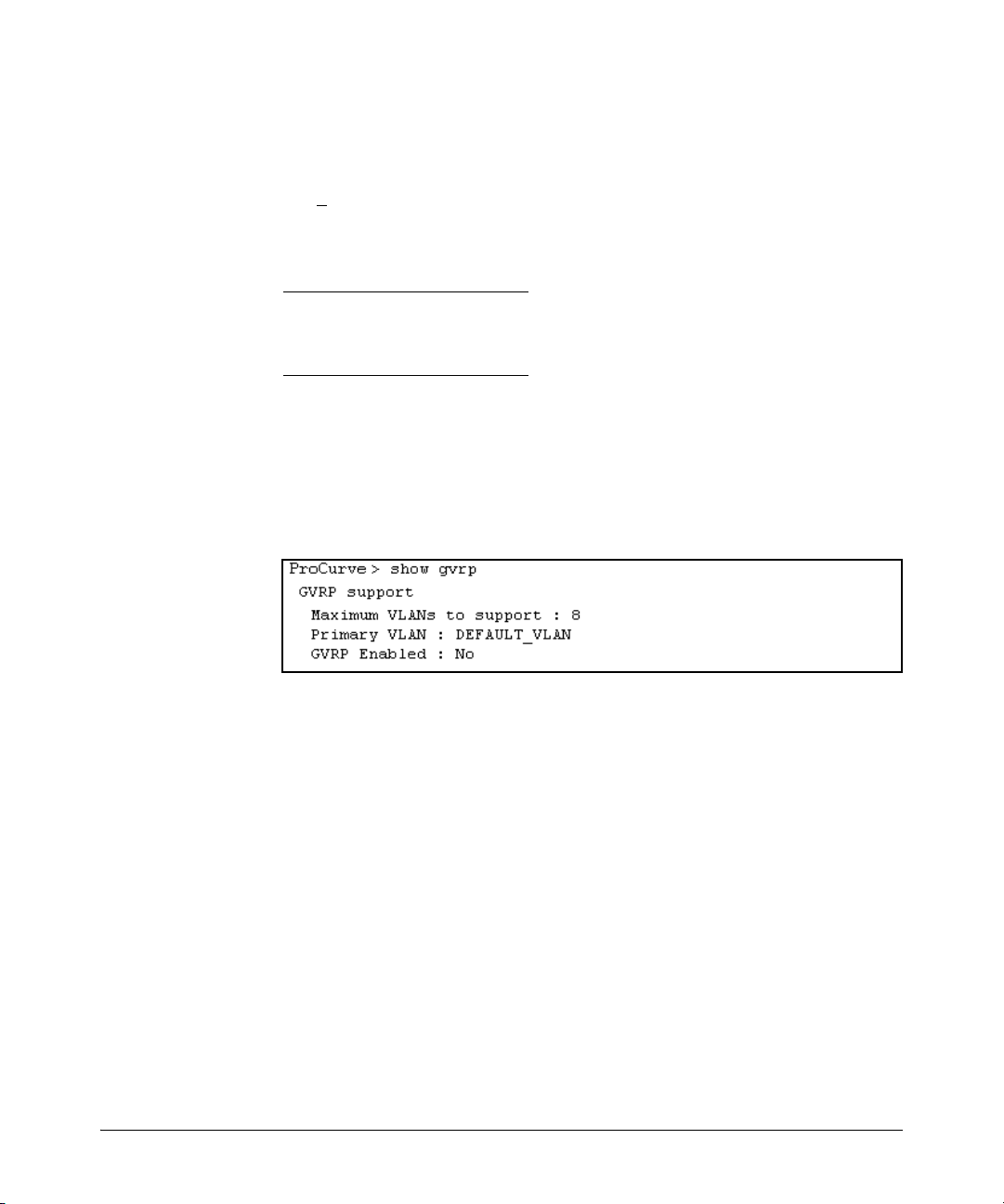
GVRP
Introduction
3. Use the arrow keys to select the port you want, and the Space bar to select
Unknown VLAN option for any ports you want to change.
4. When you finish making configuration changes, press [Enter], then [S] (for
ave) to save your changes to the Startup-Config file.
S
CLI: Viewing and Configuring GVRP
GVRP Commands Used in This Section
show gvrp below
gvrp page 3-14
unknown-vlans page 3-14
Displaying the Switch’s Current GVRP Configuration. This command
shows whether GVRP is disabled, along with the current settings for the
maximum number of VLANs and the current Primary VLAN. (For more on the
last two parameters, see “Port-Based Virtual LANs (Static VLANs)” on page
2-3.)
Syntax: show gvrp Shows the current settings.
Figure 3-6. Example of “Show GVRP” Listing with GVRP Disabled
3-13
Page 72

GVRP
Introduction
This example includes
non-default settings for
the Unknown VLAN field
for some ports.
Figure 3-7. Example of Show GVRP Listing with GVRP Enabled
Enabling and Disabling GVRP on the Switch. This command enables
GVRP on the switch.
Syntax: gvrp
This example enables GVRP:
ProCurve(config)# gvrp
This example disables GVRP operation on the switch:
ProCurve(config)# no gvrp
Enabling and Disabling GVRP On Individual Ports. When GVRP is
enabled on the switch, use the unknown-vlans command to change the
Unknown VLAN field for one or more ports. You can use this command at
either the Manager level or the interface context level for the desired port(s).
Syntax: interface <port-list> unknown-vlans < learn | block | disable >
Changes the Unknown VLAN field setting for the specified
port(s).
For example, to change and view the configuration for ports A1-A2 to Block:
3-14
Page 73

GVRP
Introduction
Figure 3-8. Example of Preventing Specific Ports from Joining Dynamic VLANs
Displaying the Static and Dynamic VLANs Active on the Switch. The
show vlans command lists all VLANs present in the switch.
Syntax: show vlans
For example, in the following illustration, switch “B” has one static VLAN (the
default VLAN), with GVRP enabled and port 1 configured to Learn for
Unknown VLANs. Switch “A” has GVRP enabled and has three static VLANs:
the default VLAN, VLAN-222, and VLAN-333. In this scenario, switch B will
dynamically join VLAN-222 and VLAN-333:
Switch “A”
GVRP enabled.
3 Static VLANs:
– DEFAULT_VLAN
– VLAN-222
– VLAN-333
Port 1: Set to
“Learn” Mode
Switch “B”
GVRP enabled.
1 Static VLANs:
– DEFAULT_VLAN
Figure 3-9. Example of Switches Operating with GVRP Enabled
The show vlans command lists the dynamic (and static) VLANs in switch “B”
after it has learned and joined VLAN-222 and VLAN-333.
3-15
Page 74

GVRP
Introduction
Dynamic VLANs
Learned from
Switch “A”
through Port 1
Figure 3-10. Example of Listing Showing Dynamic VLANs
Converting a Dynamic VLAN to a Static VLAN. If a port on the switch
has joined a dynamic VLAN, you can use the following command to convert
that dynamic VLAN to a static VLAN:
Syntax: static <dynamic-vlan-id>
For example, to convert dynamic VLAN 333 (from the previous example) to a
static VLAN:
3-16
ProCurve(config)# static 333
When you convert a dynamic VLAN to a static VLAN, all ports on the switch
are assigned to the VLAN in Auto mode.
Web: Viewing and Configuring GVRP
To view, enable, disable, or reconfigure GVRP:
1. Click on the Configuration tab.
2. Click on VLAN Configuration and do the following:
a. To enable or disable GVRP, click on GVRP Enabled.
b. To change the Unknown VLAN field for any port:
i. Click on GVRP Security and make the desired changes.
ii. Click on Apply to save and implement your changes to the
Unknown VLAN fields.
For web-based Help on how to use the web browser interface screen, click on
the
[?] button provided on the web browser screen.
Page 75

GVRP
Introduction
GVRP Operating Notes
■ A dynamic VLAN must be converted to a static VLAN before it can have
an IP address.
■ The total number of VLANs on the switch (static and dynamic combined)
cannot exceed the current Maximum VLANs setting. For example, in the
factory default state, the switch supports eight VLANs. Thus, in a case
where four static VLANs are configured on the switch, the switch can
accept up to four additional VLANs in any combination of static and
dynamic. Any additional VLANs advertised to the switch will not be added
unless you first increase the Maximum VLANs setting. In the Menu interface, click on 2. Switch Configuration ... | 8. VLAN Menu | 1. VLAN Support. In
the global config level of the CLI, use max-vlans.
■ Converting a dynamic VLAN to a static VLAN and then executing the write
memory command saves the VLAN in the startup-config file and makes it
a permanent part of the switch’s VLAN configuration.
■ Within the same broadcast domain, a dynamic VLAN can pass through a
device that is not GVRP-aware. This is because a hub or a switch that is
not GVRP-ware will flood the GVRP (multicast) advertisement packets
out all ports.
■ GVRP assigns dynamic VLANs as Tagged VLANs. To configure the VLAN
as Untagged, you must first convert it to a static VLAN.
■ Rebooting a switch on which a dynamic VLAN exists deletes that VLAN.
However, the dynamic VLAN re-appears after the reboot if GVRP is
enabled and the switch again receives advertisements for that VLAN
through a port configured to add dynamic VLANs.
■ By receiving advertisements from other devices running GVRP, the switch
learns of static VLANs on those other devices and dynamically (automatically) creates tagged VLANs on the links to the advertising devices.
Similarly, the switch advertises its static VLANs to other GVRP-aware
devices, as well as the dynamic VLANs the switch has learned.
■ A GVRP-enabled switch does not advertise any GVRP-learned VLANs out
of the port(s) on which it originally learned of those VLANs.
3-17
Page 76

GVRP
Introduction
3-18
Page 77

Multimedia Traffic Control with IP Multicast (IGMP)
Contents
Overview . . . . . . . . . . . . . . . . . . . . . . . . . . . . . . . . . . . . . . . . . . . . . . . . . . . . . . 4-2
General Operation and Features . . . . . . . . . . . . . . . . . . . . . . . . . . . . . . . . . . 4-3
IGMP Features . . . . . . . . . . . . . . . . . . . . . . . . . . . . . . . . . . . . . . . . . . . . . . 4-3
IGMP Terms . . . . . . . . . . . . . . . . . . . . . . . . . . . . . . . . . . . . . . . . . . . . . . . . 4-4
IGMP Operating Features . . . . . . . . . . . . . . . . . . . . . . . . . . . . . . . . . . . . . 4-5
Basic Operation . . . . . . . . . . . . . . . . . . . . . . . . . . . . . . . . . . . . . . . . . 4-5
Enhancements . . . . . . . . . . . . . . . . . . . . . . . . . . . . . . . . . . . . . . . . . . 4-5
CLI: Configuring and Displaying IGMP . . . . . . . . . . . . . . . . . . . . . . . . . . . . . 4-6
4
Web: Enabling or Disabling IGMP . . . . . . . . . . . . . . . . . . . . . . . . . . . . . . . . 4-11
How IGMP Operates . . . . . . . . . . . . . . . . . . . . . . . . . . . . . . . . . . . . . . . . . . . 4-11
IGMP Operating Notes . . . . . . . . . . . . . . . . . . . . . . . . . . . . . . . . . . . . . . 4-12
Displaying IGMP Data. . . . . . . . . . . . . . . . . . . . . . . . . . . . . . . . . . . 4-12
Supported Standards and RFCs . . . . . . . . . . . . . . . . . . . . . . . . . . . . . . 4-13
Operation With or Without IP Addressing . . . . . . . . . . . . . . . . . . . . . . 4-13
Automatic Fast-Leave IGMP . . . . . . . . . . . . . . . . . . . . . . . . . . . . . . . . . 4-14
Using Delayed Group Flush . . . . . . . . . . . . . . . . . . . . . . . . . . . . . . . . . . 4-17
Forced Fast-Leave IGMP . . . . . . . . . . . . . . . . . . . . . . . . . . . . . . . . . . . . 4-17
Setting Fast-Leave and Forced Fast-Leave from the CLI . . . . . . . . . . 4-17
Setting Forced Fast-Leave Using the MIB . . . . . . . . . . . . . . . . . . . 4-18
Listing the MIB-Enabled Forced Fast-Leave Configuration . . . . 4-18
Configuring Per-Port Forced Fast-Leave IGMP . . . . . . . . . . . . . . . . . . 4-20
Using the Switch as Querier . . . . . . . . . . . . . . . . . . . . . . . . . . . . . . . . . . . . . 4-21
Querier Operation . . . . . . . . . . . . . . . . . . . . . . . . . . . . . . . . . . . . . . . . . . 4-21
Excluding Multicast Addresses from IP Multicast Filtering . . . . . . . . . . . 4-22
4-1
Page 78

Multimedia Traffic Control with IP Multicast (IGMP)
Overview
Overview
This chapter describes Multimedia Traffic Control with IP Multicast (IGMP),
and explains how to configure IGMP controls to reduce unnecessary
bandwidth usage on a per-port basis.
For the latest information on IGMP, see the software release notes posted on
the ProCurve Networking support web site at http://www.procurve.com.
For general information on how to use the switch’s built-in interfaces, refer to
these chapters in the Management and Configuration Guide for your switch:
■ Chapter 3, “Using the Menu Interface”
■ Chapter 4, “Using the Command Line Interface (CLI)”
■ Chapter 5, “Using the Web Browser Interface”
■ Appendix C, “Switch Memory and Configuration”
4-2
Page 79

Multimedia Traffic Control with IP Multicast (IGMP)
General Operation and Features
General Operation and Features
IGMP Features
Feature Default Menu CLI Web
view igmp configuration n/a — page 4-6 —
show igmp status for multicast
groups used by the selected
VLAN
enabling or disabling IGMP
(Requires VLAN ID Context)
per-port packet control auto — page 4-9 —
IGMP traffic priority normal — page 4-10 —
querier enabled — page 4-10 —
fast-leave disabled — page 4-14 —
n/a — Yes —
disabled — page 4-8 page 4-11
In a network where IP multicast traffic is transmitted for various multimedia
applications, you can use the switch to reduce unnecessary bandwidth usage
on a per-port basis by configuring IGMP (Internet Group Management
Protocol controls). In the factory default state (IGMP disabled), the switch
simply floods all IP multicast traffic it receives on a given VLAN through all
ports on that VLAN (except the port on which it received the traffic). This can
result in significant and unnecessary bandwidth usage in networks where IP
multicast traffic is a factor. Enabling IGMP allows the ports to detect IGMP
queries and report packets and manage IP multicast traffic through the switch.
IGMP is useful in multimedia applications such as LAN TV, desktop
conferencing, and collaborative computing, where there is multipoint
communication; that is, communication from one to many hosts, or
communication originating from many hosts and destined for many other
hosts. In such multipoint applications, IGMP will be configured on the hosts,
and multicast traffic will be generated by one or more servers (inside or
outside of the local network). Switches in the network (that support IGMP)
can then be configured to direct the multicast traffic to only the ports where
needed. If multiple VLANs are configured, you can configure IGMP on a perVLAN basis.
4-3
Page 80

Multimedia Traffic Control with IP Multicast (IGMP)
General Operation and Features
Enabling IGMP allows detection of IGMP queries and report packets in order
to manage IP multicast traffic through the switch. If no other querier is
detected, the switch will then also function as the querier. (If you need to
disable the querier feature, you can do so through the IGMP configuration
MIB. Refer to “Changing the Querier Configuration Setting” on page 4-10.)
Note IGMP configuration on the switch operates at the VLAN context level. If you
are not using VLANs, then configure IGMP in VLAN 1 (the default VLAN)
context.
IGMP Terms
■ IGMP Device: A switch or router running IGMP traffic control
features.
■ IGMP Host: An end-node device running an IGMP (multipoint, or
multicast communication) application.
■ Querier: A required IGMP device that facilitates the IGMP protocol
and traffic flow on a given LAN. This device tracks which ports are
connected to devices (IGMP clients) that belong to specific multicast
groups, and triggers updates of this information. A querier uses data
received from the queries to determine whether to forward or block
multicast traffic on specific ports. When the switch has an IP address
on a given VLAN, it automatically operates as a Querier for that VLAN
if it does not detect a multicast router or another switch functioning
as a Querier. When enabled (the default state), the switch’s querier
function eliminates the need for a multicast router. In most cases,
ProCurve recommends that you leave this parameter in the default
“enabled” state even if you have a multicast router performing the
querier function in your multicast group. For more information, see
“How IGMP Operates” on page 4-11.
4-4
Page 81

Multimedia Traffic Control with IP Multicast (IGMP)
General Operation and Features
IGMP Operating Features
Basic Operation
In the factory default configuration, IGMP is disabled. If multiple VLANs are
not configured, you must configure IGMP on the default VLAN
(DEFAULT_VLAN; VID = 1). If multiple VLANs are configured, you must
configure IGMP on a per-VLAN basis for every VLAN where this feature is
desired.
Enhancements
With the CLI, you can configure these additional options:
■ Forward with High Priority. Disabling this parameter (the default)
causes the switch or VLAN to process IP multicast traffic, along with other
traffic, in the order received (usually, normal priority). Enabling this
parameter causes the switch or VLAN to give a higher priority to IP
multicast traffic than to other traffic.
■ Auto/Blocked/Forward: You can use the console to configure individual
ports to any of the following states:
• Auto (the default): Causes the switch to interpret IGMP packets and
to filter IP multicast traffic based on the IGMP packet information for
ports belonging to a multicast group. This means that IGMP traffic
will be forwarded on a specific port only if an IGMP host or multicast
router is connected to the port.
• Blocked: Causes the switch to drop all IGMP transmissions received
from a specific port and to block all outgoing IP Multicast packets for
that port. This has the effect of preventing IGMP traffic from moving
through specific ports.
• Forward: Causes the switch to forward all IGMP and IP multicast
transmissions through the port.
■ Operation With or Without IP Addressing: This feature helps to
conserve IP addresses by enabling IGMP to run on VLANs that do not have
an IP address. See “Operation With or Without IP Addressing” on page
4-13.
■ Querier Capability: The switch performs this function for IGMP on
VLANs having an IP address when there is no other device in the VLAN
acting as querier. See “Querier Operation” on page 4-21.
4-5
Page 82

Multimedia Traffic Control with IP Multicast (IGMP)
CLI: Configuring and Displaying IGMP
Notes Whenever IGMP is enabled, the switch generates an Event Log message
indicating whether querier functionality is enabled.
IP multicast traffic groups are identified by IP addresses in the range of
224.0.0.0 to 239.255.255.255. Also, incoming IGMP packets intended for
reserved, or “well-known” multicast addresses automatically flood through all
ports (except the port on which the packets entered the switch). For more on
this topic, see “Excluding Multicast Addresses from IP Multicast Filtering” on
page 4-22.
For more information, refer to “How IGMP Operates” on page 4-11.
CLI: Configuring and Displaying IGMP
IGMP Commands Used in This Section
show ip igmp configuration
config
vid [config]
group <ip address>
ip igmp page 4-8
high-priority-forward page 4-10
auto <[ethernet] <port-list> page 4-9
blocked <[ethernet] <port-list> page 4-9
forward <[ethernet] <port-list> page 4-9
querier page 4-10
show ip igmp See the appendix on monitoring and analyzing switch
page 4-7
operation in the Management and Configuration
Guide.
4-6
Page 83
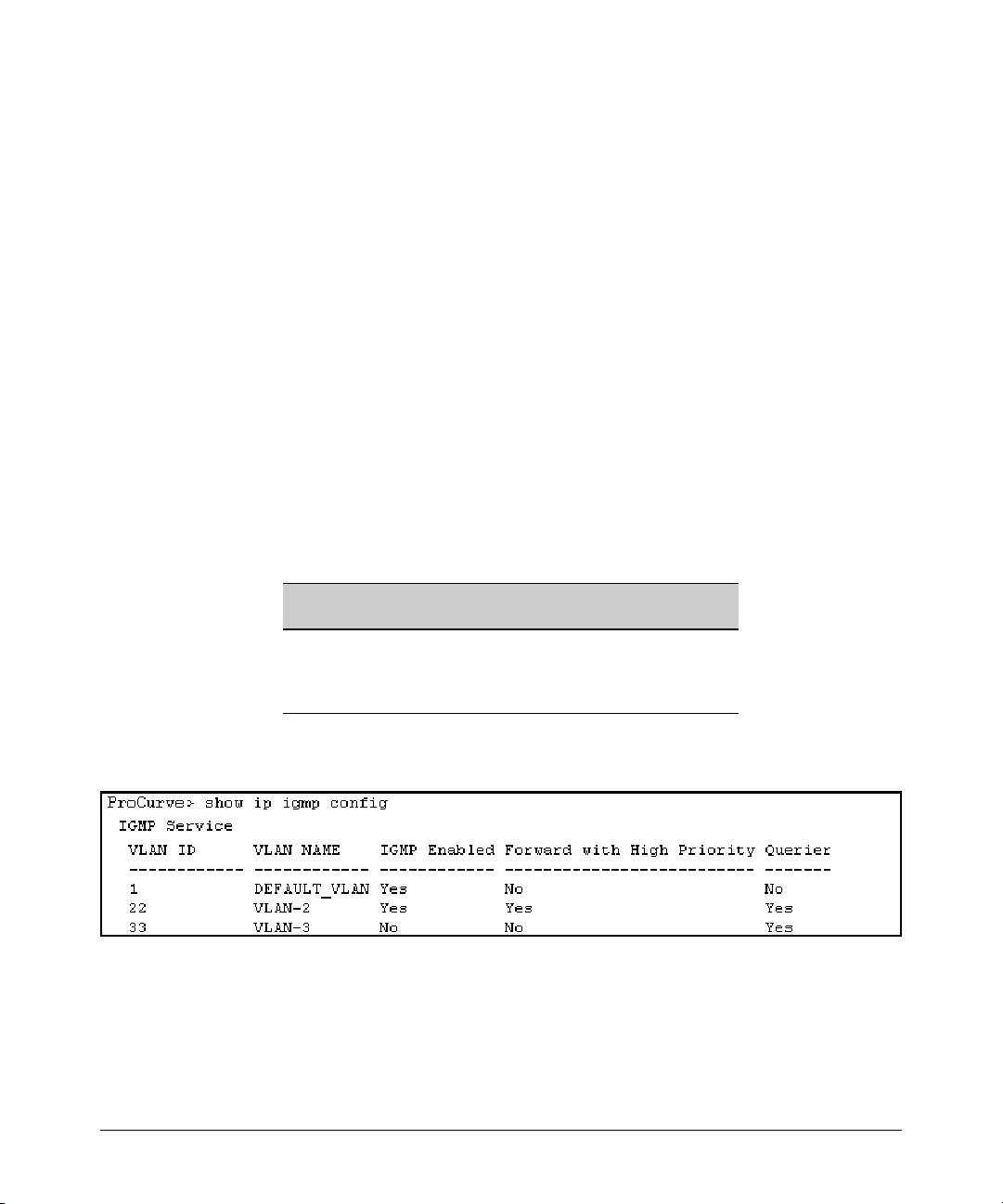
Multimedia Traffic Control with IP Multicast (IGMP)
CLI: Configuring and Displaying IGMP
Viewing the Current IGMP Configuration. This command lists the IGMP
configuration for all VLANs configured on the switch or for a specific VLAN.
Syntax: show ip igmp config
IGMP configuration for all VLANs on the switch.
Syntax: show ip igmp < vid > config
IGMP configuration for a specific VLAN on the switch, including
per-port data
Syntax: show ip igmp group < ip-address >
Lists the ports on which the specified multicast group IP address
is registered.
(For IGMP operating status, see the appendix on monitoring and analyzing
switch operation in the Management and Configuration Guide.)
For example, suppose you have the following VLAN and IGMP configurations
on the switch:
VLAN ID VLAN Name IGMP
Enabled
1 DEFAULT_VLAN Yes No No
22 VLAN-2 Yes Yes Yes
33 VLAN-3 No No No
Forward with
High Priority
You could use the CLI to display this data as follows:
Figure 4-1. Example Listing of IGMP Configuration for All VLANs in the Switch
The following version of the show ip igmp command includes the VLAN ID (
designation, and combines the above data with the IGMP per-port
configuration:
Querier
vid)
4-7
Page 84

Multimedia Traffic Control with IP Multicast (IGMP)
CLI: Configuring and Displaying IGMP
IGMP Configuration
for the Selected
VLAN
IGMP Configuration
On the Individual
Ports in the VLAN
Figure 4-2. Example Listing of IGMP Configuration for A Specific VLAN
Enabling or Disabling IGMP on a VLAN. You can enable IGMP on a
VLAN, along with the last-saved or default IGMP configuration (whichever
was most recently set), or you can disable IGMP on a selected VLAN. Note
that this command must be executed in a VLAN context.
Syntax: [no] ip igmp
For example, here are methods to enable and disable IGMP on the default
VLAN (VID = 1).
ProCurve(config)# vlan 1 ip igmp
Enables IGMP on VLAN 1.
ProCurve(vlan-1)# ip igmp
Same as above.
ProCurve(config)# no vlan 1 ip igmp
Disables IGMP on VLAN 1.
Note If you disable IGMP on a VLAN and then later re-enable IGMP on that VLAN,
the switch restores the last-saved IGMP configuration for that VLAN. For more
on how switch memory operates, see the chapter on switch memory and
configuration in the Management and Configuration Guide.
4-8
Page 85

Multimedia Traffic Control with IP Multicast (IGMP)
CLI: Configuring and Displaying IGMP
You can also combine the ip igmp command with other IGMP-related
commands, as described in the following sections.
Configuring Per-Port IGMP Packet Control. Use this command in the
VLAN context to specify how each port should handle IGMP traffic.
Syntax: vlan < vid > ip igmp
[ auto <port-list> | blocked <port-list> | forward <port-list> ]
Syntax: vlan < vid > ip igmp
Enables IGMP on the specified VLAN. In a VLAN context,
use only
auto
< port-list > (Default operation)
ip igmp without the VLAN specifier.
Filter multicast traffic on the specified ports. Forward
IGMP traffic to hosts on the ports that belong to the
multicast group for which the traffic is intended. (Also
forward any multicast traffic through any of these ports
that is connected to a multicast router.) This is the default
IGMP port configuration.
blocked < port-list >
Drop all multicast traffic received from devices on the
specified ports, and prevent any outgoing multicast
traffic from moving through these ports.
forward < port-list >
Forward all multicast traffic through the specified port.
For example, suppose you wanted to configure IGMP as follows for VLAN 1
on ports A1 - A6:
■ Ports A1 - A2: Auto
■ Ports A3 - A4: Forward
■ Ports A5 - A6: Block
Depending on the privilege level, you could use one of the following
commands to configure IGMP on VLAN 1 with the above settings:
ProCurve(config)# vlan 1
ProCurve(vlan-1)# ip igmp auto a1,a2
ProCurve(vlan-1)# ip igmp forward a3,a4
ProCurve(vlan-1)# ip igmp blocked a5,a6
4-9
Page 86

Multimedia Traffic Control with IP Multicast (IGMP)
CLI: Configuring and Displaying IGMP
The following command displays the VLAN and per-port configuration
resulting from the above commands.
ProCurve> show ip igmp 1 config
Configuring IGMP Traffic Priority. This command allows you to
prioritize IGMP traffic as either “high” or “normal” (the default).
Syntax:
[no] vlan < vid > ip igmp high-priority-forward
Assigns “high” priority to IGMP traffic. The “
no” form
returns a high-priority setting to (the default) “normal”
priority. (The switch services the traffic at its inbound
priority.)
ProCurve(config)# vlan 1 ip igmp high-priority-forward
This example configures high priority for IGMP traffic on
VLAN 1.
ProCurve(vlan-1)# ip igmp high-priority-forward
Same as above command, but in the VLAN 1 context
level.
ProCurve(vlan 1)# no ip igmp high-priority-forward
Returns IGMP traffic to “normal” priority.
ProCurve> show ip igmp config
Show command to display results of above high-priority
commands.
Configuring the Querier Function. In its default configuration, the switch
is capable of operating as an IGMP querier. This command lets you disable or
re-enable this function.
Syntax: [no] vlan <vid> ip igmp querier
Disables or re-enables the ability for the switch to become
querier, if necessary, on the specified VLAN. The default
querier capability is “enabled”.
4-10
ProCurve(config)# no vlan 1 ip igmp querier
Disables the querier function on VLAN 1.
ProCurve> show ip igmp config
This is the show command used to display results of the
above querier command.
Page 87

Multimedia Traffic Control with IP Multicast (IGMP)
Web: Enabling or Disabling IGMP
Web: Enabling or Disabling IGMP
In the web browser interface you can enable or disable IGMP on a per-VLAN
basis. To configure other IGMP features, telnet to the switch console and use
the CLI.
To Enable or Disable IGMP:
1. Click on the Configuration tab.
2. Click on the Device Features button.
3. If more than one VLAN is configured, use the VLAN pull-down menu to
select the VLAN on which you want to enable or disable IGMP.
4. Use the Multicast Filtering (IGMP) menu to enable or disable IGMP.
5. Click on Apply Changes button to implement the configuration change.
For web-based help on how to use the web browser interface screen, click on
the ? button provided on the web browser screen.
How IGMP Operates
The Internet Group Management Protocol (IGMP) is an internal protocol of
the Internet Protocol (IP) suite. IP manages multicast traffic by using
switches, multicast routers, and hosts that support IGMP. (In ProCurve’s
implementation of IGMP, a multicast router is not necessary as long as a
switch is configured to support IGMP with the querier feature enabled.) A set
of hosts, routers, and/or switches that send or receive multicast data streams
to or from the same source(s) is termed a multicast group, and all devices in
the group use the same multicast group address.
Message Types
The multicast group running version 2 of IGMP uses three fundamental types
of messages to communicate:
■ Query: A message sent from the querier (multicast router or switch)
asking for a response from each host belonging to the multicast group. If
a multicast router supporting IGMP is not present, then the switch must
assume this function in order to elicit group membership information
4-11
Page 88

Multimedia Traffic Control with IP Multicast (IGMP)
How IGMP Operates
from the hosts on the network. (If you need to disable the querier feature,
you can do so through the CLI, using the IGMP configuration MIB. See
“Configuring the Querier Function” on page 4-10.)
■ Report (Join): A message sent by a host to the querier to indicate that
the host wants to be or is a member of a given group indicated in the report
message.
■ Leave Group: A message sent by a host to the querier to indicate that the
host has ceased to be a member of a specific multicast group.
IGMP Operating Notes
IGMP identifies members of a multicast group (within a subnet) and allows
IGMP-configured hosts (and routers) to join or leave multicast groups based
on the following process.
■ An IP multicast packet includes the multicast group (address) to which
the packet belongs.
■ When an IGMP client connected to a switch port needs to receive multi-
cast traffic from a specific group, it joins the group by sending an IGMP
report (join request) to the network. (The multicast group specified in the
join request is determined by the requesting application running on the
IGMP client.)
■ When a networking device with IGMP enabled receives the join request
for a specific group, it forwards any IP multicast traffic it receives for that
group through the port on which the join request was received.
■ When the client is ready to leave the multicast group, it sends a Leave
Group message to the network and ceases to be a group member.
■ When the leave request is detected, the appropriate IGMP device will
cease transmitting traffic for the designated multicast group through the
port on which the leave request was received (as long as there are no other
current members of that group on the affected port).
4-12
Displaying IGMP Data.
To display data showing active group addresses, reports, queries, querier
access port, and active group address data (port, type, and access), see the
appendix on monitoring and analyzing switch operation in the Management
and Configuration Guide.
Page 89

Multimedia Traffic Control with IP Multicast (IGMP)
How IGMP Operates
Supported Standards and RFCs
ProCurve’s implementation of IGMP supports the following standards and
operating capabilities:
• RFC2236 (IGMP V.2, with backwards support for IGMP V.1)
• IETF draft for IGMP and MLD snooping switches (for IGMP V1,
V2 V3)
• Full IGMPv2 support as well as full support for IGMPv1 Joins.
• Ability to operate in IGMPv2 Querier mode on VLANs with an IP
address.
The ProCurve implementation is subject to the following restrictions:
• Interoperability with RFC3376 (IGMPv3)
• Interoperability with IGMPv3 Joins. When the switch receives an
IGMPv3 Join, it accepts the host request and begins forwarding
the IGMP traffic. This means ports that have not joined the group
and are not connected to routers or the IGMP Querier will not
receive the group's multicast traffic.
• No support for the IGMPv3 “Exclude Source” or “Include Source”
options in the Join Reports. Rather, the group is simply joined
from all sources.
• No support for becoming a version 3 Querier. The switch will
become a version 2 Querier in the absence of any other Querier
on the network.
Note IGMP is supported in the HP MIB, rather than the standard IGMP MIBs, as the
latter reduce Group Membership detail in switched environments.
Operation With or Without IP Addressing
You can configure IGMP on VLANs that do not have IP addressing. The benefit
of IGMP without IP addressing is a reduction in the number of IP addresses
you have to use and configure. This can be significant in a network with a large
number of VLANs. The limitation on IGMP without IP addressing is that the
switch cannot become Querier on any VLANs for which it has no IP address—
so the network administrator must ensure that another IGMP device will act
as Querier. It is also advisable to have an additional IGMP device available as
a backup Querier. See the following table.
4-13
Page 90

Multimedia Traffic Control with IP Multicast (IGMP)
How IGMP Operates
Table 4-1.Comparison of IGMP Operation With and Without IP Addressing
IGMP Function Available With IP Addressing
Configured on the VLAN
Forward multicast group traffic to any port on
the VLAN that has received a join request for
that multicast group.
Forward join requests (reports) to the Querier. Yes None
Configure individual ports in the VLAN to Auto
(the default)/Blocked, or Forward.
Configure IGMP traffic forwarding to normal or
high-priority forwarding.
Age-Out IGMP group addresses when the last
IGMP client on a port in the VLAN leaves the
group.
Support Fast-Leave IGMP (below) and Forced
Fast-Leave IGMP (page 4-14).
Support automatic Querier election. No Querier operation not available.
Operate as the Querier. No Querier operation not available.
Available as a backup Querier. No Querier operation not available.
Available
Without IP
Addressing?
Yes None
Yes None
Yes None
Yes Requires that another IGMP device in the VLAN has an IP
Yes
Operating Differences
Without an IP Address
address and can operate as Querier. This can be a
multicast router or another switch configured for IGMP
operation. (ProCurve recommends that the VLAN also
include a device operating as a backup Querier in case
the device operating as the primary Querier fails for any
reason.
4-14
Automatic Fast-Leave IGMP
IGMP Operation Presents a “Delayed Leave” Problem. Where multiple
IGMP clients are connected to the same port on an IGMP device (switch or
router), if only one IGMP client joins a given multicast group, then later sends
a Leave Group message and ceases to belong to that group, the IGMP device
retains that IGMP client in its IGMP table and continues forwarding IGMP
traffic to the IGMP client until the Querier triggers confirmation that no other
group members exist on the same port. This means that the switch continues
to transmit unnecessary multicast traffic through the port until the Querier
renews the multicast group status.
Fast-Leave IGMP. Depending on the switch model, Fast-Leave is enabled
or disabled in the default configuration.
Page 91

Multimedia Traffic Control with IP Multicast (IGMP)
Table 4-2.IGMP: Data-Driven and Non-Data Driven Behavior
How IGMP Operates
Switch Model or
Series
Switch 5300
Switch 2800
Switch 2810
Switch 2500
Switch 2600
Switch 2600-PWR
Switch 4100
Switch 6108
Data-
Driven
IGMP
Included?
Yes Always
No Disabled in
IGMP Fast-
Leave Setting
Enabled
the Default
Configuration
Default IGMP Behavior
Drops unjoined multicast traffic except for
always-forwarded traffic toward the Querier
or multicast routers, and out of IGMP-forward
ports. Selectively forwards joined multicast
traffic.
IGMP Fast-Leave disabled in the default
configuration. Floods unjoined multicast
traffic to all ports. Selectively forwards joined
multicast traffic.
On switches that do not support Data-Driven IGMP, unregistered multicast
groups are flooded to the VLAN rather than pruned. In this scenario, FastLeave IGMP can actually increase the problem of multicast flooding by
removing the IGMP group filter before the Querier has recognized the IGMP
Leave. The Querier will continue to transmit the multicast group during this
short time, and because the group is no longer registered the switch will then
flood the multicast group to all ports.
On ProCurve switches that do support Data-Driven IGMP (“Smart” IGMP),
when unregistered multicasts are received the switch automatically filters
(drops) them. Thus, the sooner the IGMP Leave is processed, the sooner this
multicast traffic stops flowing.
Because of the multicast flooding problem mentioned above, the IGMP
FastLeave feature is disabled by default on all ProCurve switches that do not
support Data-Driven IGMP. (See table 4-2, above.) The feature can be enabled
on these switches via an SNMP set of this object:
hpSwitchIgmpPortForceLeaveState.< vid >.< port number>
However, this is not recommended as this will increase the amount of
multicast flooding during the period between the client's IGMP Leave and the
Querier's processing of that Leave. For more on this topic, refer to “Forced
Fast-Leave IGMP” on page 4-17.
ProCurve recommends that the following settings be used.
■ Use Delayed Group Flush on the Series 2600 switches whenever Fast
Leave or Forced Fast Leave are set on a port (see page 4-17).
■ Forced fast leave can be used when there are multiple devices
attached to a port.
4-15
Page 92

Multimedia Traffic Control with IP Multicast (IGMP)
How IGMP Operates
Automatic Fast-Leave Operation. If a switch port is:
a. Connected to only one end node
b. The end node currently belongs to a multicast group; i.e. is an IGMP
client
c. The end node subsequently leaves the multicast group
Then the switch does not need to wait for the Querier status update interval,
but instead immediately removes the IGMP client from its IGMP table and
ceases transmitting IGMP traffic to the client. (If the switch detects multiple
end nodes on the port, automatic Fast-Leave does not activate—regardless of
whether one or more of these end nodes are IGMP clients.)
In the next figure, automatic Fast-Leave operates on the switch ports for IGMP
clients “3A” and “5A”, but not on the switch port for IGMP clients “7A” and 7B,
Server “7C”, and printer “7D”.
Fast-Leave IGMP
automatically operates
on the ports connected
to IGMP clients 3A and
5A, but does not
operate on the port
connected to Switch 7X
because the switch
detects multiple end
nodes on that port.
Routing
Switch
Acting as
Querier
Fast-Leave IGMP
activates on these
two ports.
3A
A1 A3
ProCurve Switch with
Automatic Fast-Leave
A4
5A
A6
7A
Fast-Leave IGMP does
not activate on this port.
Switch 7X
7B
Server
7C
Printer
7D
Figure 4-3. Example of Automatic Fast-Leave IGMP Criteria
When client “3A” running IGMP is ready to leave the multicast group, it
transmits a Leave Group message. Because the switch knows that there is only
one end node on port A3, it removes the client from its IGMP table and halts
multicast traffic (for that group) to port A3. If the switch is not the Querier, it
does not wait for the actual Querier to verify that there are no other group
members on port A3. If the switch itself is the Querier, it does not query port
A3 for the presence of other group members.
Note that Fast-Leave operation does not distinguish between end nodes on
the same port that belong to different VLANs. Thus, for example, even if all of
the devices on port A6 in figure 4-3 belong to different VLANs, Fast-Leave does
not operate on port A6.
4-16
Page 93

Multimedia Traffic Control with IP Multicast (IGMP)
How IGMP Operates
Using Delayed Group Flush
This feature continues to filter IGMP-Left groups for a specified additional
period of time. The delay in flushing the group filter prevents stale traffic from
being forwarded by the server. Delayed Group Flush is enabled or disabled
for the entire switch.
Syntax:
Syntax: Show igmp delayedflush
igmp delayedflush <time period>
Enables the switch to continue to flush IGMP-Left groups
for a specified period of time (0 - 255 seconds). The default
setting is Disabled. To disable, reset the time period to zero.
Displays the current setting for the switch.
Forced Fast-Leave IGMP
Forced Fast-Leave IGMP speeds up the process of blocking unnecessary IGMP
traffic to a switch port that is connected to multiple end nodes. (This feature
does not activate on ports where the switch detects only one end node). For
example, in figure 4-3, even if you configured Forced Fast-Leave on all ports
in the switch, the feature would activate only on port A6 (which has multiple
end nodes) when a Leave Group request arrived on that port.
When a port having multiple end nodes receives a Leave Group request from
one end node for a given multicast group “X”, Forced Fast-Leave activates and
waits a small amount of time to receive a join request from any other group
“X” member on that port. If the port does not receive a join request for that
group within the forced-leave interval, the switch then blocks any further
group “X” traffic to the port.
Setting Fast-Leave and Forced Fast-Leave from the CLI
In previous software versions, Fast-Leave and Forced Fast-Leave options for
a port were set exclusively through the MIB
allow a port to be configured for Fast-Leave or Forced Fast-leave operation
from the CLI. Note that these commands must be executed in a VLAN context
. The following commands now
4-17
Page 94

Multimedia Traffic Control with IP Multicast (IGMP)
How IGMP Operates
Syntax: [no] ip igmp fastleave <port-list>
Enables IGMP Fast-Leaves on the specified ports in the VLAN
(the default setting). In the Config context, use the VLAN
specifier, for example, vlan < vid > ip igmp fastleave <port-list>.
The “no” form disables Fast-Leave on the specified ports.
[no] ip igmp forcedfastleave <port-list>
Forces IGMP Fast-Leaves on the specified ports in the VLAN,
even if they are cascaded.
To view the IGMP Fast-Leave status of a port use the show running-config or
show configuration commands.
Setting Forced Fast-Leave Using the MIB
Fast-Leave and Forced Fast-Leave options for a port can also be set through
the switch’s MIB (Management Information Base).
Feature Default Settings Function
Forced FastLeave state2 (disabled)
1 (enabled)
2 (disabled)
Uses the setmib command to enable or disable
Forced Fast-Leave on individual ports. When
enabled on a port, Forced Fast-Leave operates only
if the switch detects multiple end nodes (and at least
one IGMP client) on that port.
Note on VLAN
Numbers
4-18
In the ProCurve switches covered in this guide, the walkmib and setmib
commands use an internal VLAN number (and not the VLAN ID, or VID) to
display or change many per-vlan features, such as the Forced Fast-Leave state.
Because the internal VLAN number for the default VLAN is always 1
(regardless of whether VLANs are enabled on the switch), and because a
discussion of internal VLAN numbers for multiple VLANs is beyond the scope
of this manual, this section concentrates on examples that use the default
VLAN.
Listing the MIB-Enabled Forced Fast-Leave Configuration
The Forced Fast-Leave configuration data is available in the switch’s MIB, and
includes the state (enabled or disabled) for each port and the Forced-Leave
Interval for all ports on the switch.
To List the Forced Fast-Leave State for all Ports in the Switch. In
the CLI, use the walkmib command, as shown below.
Page 95

1. Enter either of the following walkmib command options:
walkmib hpSwitchIgmpPortForcedLeaveState
- OR -
walkmib 1.3.6.1.4.1.11.2.14.11.5.1.7.1.15.3.1.5
The resulting display lists the Forced Fast-Leave state for all ports in the
switch, by VLAN. (A port belonging to more than one VLAN will be listed
once for each VLAN, and if multiple VLANs are not configured, all ports
will be listed as members of the default VLAN.) The following command
produces a listing such as that shown in figure 4-4:
Internal VLAN Number for the Default VLAN
Note: Internal VLAN numbers reflect the sequence
in which VLANs are created, and are not re lated to
the unique VID assigned to each VLAN. (See the
“Note on VLAN Numbers on page 4-18.)
Multimedia Traffic Control with IP Multicast (IGMP)
Sequential Port
Numbers
Ports 1-6: 6- Port 109/1000T Module in Slot A
How IGMP Operates
The 2 at the end of a port
listing shows that Forced
Fast-Leave is disabled on
the corresponding port.
1 at the end of a port
The
listing shows that Forced
Fast-Leave is enabled on
the corresponding port.
Figure 4-4. Example of a Forced Fast-Leave Listing where all Ports are Members of the Default VLAN
To List the Forced Fast-Leave State for a Single Port. (See the “Note
on VLAN Numbers” on page 4-18.)
Go to the switch’s command prompt and use the getmib command, as shown
below.
Syntax:
getmib hpSwitchIgmpPortForcedLeaveState.<vlan number><.port number>
- OR -
getmib 1.3.6.1.4.1.11.2.14.11.5.1.7.1.15.3.1.5.<vlan number><.port number>
For example, the following command to list the state for port A6 (which,
in this case, belongs to the default VLAN) produces the indicated listing:
4-19
Page 96

Multimedia Traffic Control with IP Multicast (IGMP)
How IGMP Operates
The 2 shows that Fast Forced-Leave
is disabled on the selected port.
6 specifies port A6.
The
1 indicates the default VLAN.
The
(See the “Note on VLAN Numbers”
on page 4-18.)
Figure 4-5. Example Listing the Forced Fast-Leave State for a Single Port on the Default
VLAN
Configuring Per-Port Forced Fast-Leave IGMP
In the factory-default configuration, Forced Fast-Leave is disabled for all ports
on the switch. To enable (or disable) this feature on individual ports, use the
switch’s setmib command, as shown below.
Configuring Per-Port Forced Fast-Leave IGMP on Ports. This
procedure enables or disables Forced Fast-Leave on ports in a given VLAN.
(See the “Note on VLAN Numbers” on page 4-18.)
4-20
Syntax:
setmib hpSwitchIgmpPortForcedLeaveState.< vlan number >< .port number >
-i < 1 | 2 >
- OR -
setmib 1.3.6.1.4.1.11.2.14.11.5.1.7.1.15.3.1.5.< vlan number >< .port number > -i
< 1 | 2 >
where:
1 = Forced Fast-Leave enabled
2 = Forced Fast-Leave disabled
For example, suppose that your switch has a six-port gigabit module in
slot A, and port C1 is a member of the default VLAN. In this case, the port
number is “49” (In the MIB, slot A = ports 1-24; slot B = ports 25-48; slot
C = ports 49-72, and so on.) To enable Forced Fast-Leave on C6 (53), you
would execute the following command and see the indicated result:
Page 97

Multimedia Traffic Control with IP Multicast (IGMP)
Figure 4-6. Example of Changing the Forced Fast-Leave Configuration on Port 49
Using the Switch as Querier
Verifies Forced Fast-Leave enabled.
49 indicates port C1.
1 indicates the default VLAN. (See
the note on page 4-18.)
Using the Switch as Querier
Querier Operation
The function of the IGMP Querier is to poll other IGMP-enabled devices in an
IGMP-enabled VLAN to elicit group membership information. The switch
performs this function if there is no other device in the VLAN, such as a
multicast router, to act as Querier. Although the switch automatically ceases
Querier operation in an IGMP-enabled VLAN if it detects another Querier on
the VLAN, you can also use the Command Prompt to disable the Querier
capability for that VLAN.
Note A Querier is required for proper IGMP operation. For this reason, if you disable
the Querier function on a switch, ensure that there is an IGMP Querier (and,
preferably, a backup Querier) available on the same VLAN.
If the switch becomes the Querier for a particular VLAN (for example, the
DEFAULT_VLAN), then subsequently detects queries transmitted from
another device on the same VLAN, the switch ceases to operate as the Querier
for that VLAN. If this occurs, the switch Event Log lists a pair of messages
similar to these:
I 01/15/01 09:01:13 igmp: DEFAULT_VLAN: Other Querier detected
I 01/15/01 09:01:13 igmp: DEFAULT_VLAN: This switch is no longer
Querier
4-21
Page 98

Multimedia Traffic Control with IP Multicast (IGMP)
Excluding Multicast Addresses from IP Multicast Filtering
In the above scenario, if the other device ceases to operate as a Querier on the
default VLAN, then the switch detects this change and can become the Querier
as long as it is not pre-empted by some other IGMP Querier on the VLAN. In
this case, the switch Event Log lists messages similar to the following to
indicate that the switch has become the Querier on the VLAN:
I 01/15/01 09:21:55 igmp: DEFAULT_VLAN: Querier Election in
process
I 01/15/01 09:22:00 igmp: DEFAULT_VLAN: This switch has been
elected as Querier
Excluding Multicast Addresses from IP
Multicast Filtering
Each multicast host group is identified by a single IP address in the range of
224.0.0.0 through 239.255.255.255. Specific groups of consecutive addresses
in this range are termed “well-known” addresses and are reserved for
predefined host groups. IGMP does not filter these addresses, so any packets
the switch receives for such addresses are flooded out all ports assigned to
the VLAN on which they were received (except the port on which the packets
entered the VLAN).
4-22
The following table lists the 32 well-known address groups (8192 total
addresses) that IGMP does not filter on the switches covered in this guide, as
well as on the 1600M, 2400M, 2424M, 2650M, 4000M, 6108M, 8000M, and Switch
2500 Series devices.
Table 4-3.IP Multicast Address Groups Excluded from IGMP Filtering
Groups of Consecutive Addresses in
the Range of 224.0.0.X to 239.0.0.X*
224.0.0.x 232.0.0.x 224.128.0.x 232.128.0.x
225.0.0.x 233.0.0.x 225.128.0.x 233.128.0.x
226.0.0.x 234.0.0.x 226.128.0.x 234.128.0.x
227.0.0.x 235.0.0.x 227.128.0.x 235.128.0.x
228.0.0.x 236.0.0.x 228.128.0.x 236.128.0.x
229.0.0.x 237.0.0.x 229.128.0.x 237.128.0.x
230.0.0.x 238.0.0.x 230.128.0.x 238.128.0.x
231.0.0.x 239.0.0.x 231.128.0.x 239.128.0.x
* X is any value from 0 to 255.
Groups of Consecutive Addresses in
the Range of 224.128.0.X to 239.128.0.X*
Page 99

Multimedia Traffic Control with IP Multicast (IGMP)
Excluding Multicast Addresses from IP Multicast Filtering
Notes: IP Multicast Filters. This operation applies to the ProCurve Switch
1600M, 2400M, 2424M, 4000M, and 8000M, but not to the Switch 2500,
2600, 2600-PWR, 2800, 2810, 4100, and 5300 Series devices or the Switch
6108 (which do not have static multicast traffic/security filters).
IP multicast addresses occur in the range from 224.0.0.0 through
239.255.255.255 (which corresponds to the Ethernet multicast address range
of 01005e-000000 through 01005e-7fffff). Where a switch has a static Traffic/
Security filter configured with a “Multicast” filter type and a “Multicast
Address” in this range, the switch will use the static filter unless IGMP learns
of a multicast group destination in this range. In this case, IGMP dynamically
takes over the filtering function for the multicast destination address(es) for
as long as the IGMP group is active. If the IGMP group subsequently
deactivates, the switch returns filtering control to the static filter.
Reserved Addresses Excluded from IP Multicast (IGMP) Filtering.
Traffic to IP multicast groups in the IP address range of 224.0.0.0 to 224.0.0.255
will always be flooded because addresses in this range are “well known” or
“reserved” addresses. Thus, if IP Multicast is enabled and there is an IP
multicast group within the reserved address range, traffic to that group will
be flooded instead of filtered by the switch.
Number of IP Multicast Addresses Allowed. Multicast filters and IGMP
filters (addresses) together can total up to 255 in the switch. If multiple VLANs
are configured, then each filter is counted once per VLAN in which it is used.
4-23
Page 100

Multimedia Traffic Control with IP Multicast (IGMP)
Excluding Multicast Addresses from IP Multicast Filtering
4-24
 Loading...