

HP J4897A, Procurve 2708, J4898A, Procurve 2724 Installation Manual
installation guide
hp procurve
series 2700 switches
www.hp.com/go/hpprocurve


z3.book Page i Friday, November 1, 2002 5:40 PM
HP Procurve
Series 2700 Switches
Installation Guide

z3.book Page ii Friday, November 1, 2002 5:40 PM
© Copyright 2002 Hewlett-Packard Company
All Rights Reserved.
This document contains information which is protected by
copyright. Reproduction, adaptation, or translation without
prior permission is prohibited, except as allowed under the
copyright laws.
Publication Number
5990-3055
October 2002
Applicable Products
HP Procurve Switch 2708 (HP J4898A)
HP Procurve Switch 2724 (HP J4897A)
Disclaimer
The information contained in this document is subject to
change without notice.
HEWLETT-PACKARD COMPANY MAKES NO WARRANTY
OF ANY KIND WITH REGARD TO THIS MATERIAL,
INCLUDING, BUT NOT LIMITED TO, THE IMPLIED
WARRANTIES OF MERCHANTABILITY AND FITNESS
FOR A PARTICULAR PURPOSE. Hewlett-Packard shall not
be liable for errors contained herein or for incidental or
consequential damages in connection with the furnishing,
performance, or use of this material.
Hewlett-Packard assumes no responsibility for the use or
reliability of its software on equipment that is not furnished
by Hewlett-Packard.
Warranty
See the Customer Support/Warranty booklet included with
the product.
A copy of the specific warranty terms applicable to your
Hewlett-Packard products and replacement parts can be
obtained from your HP Sales and Service Office or
authorized dealer.
Hewlett-Packard Company
8000 Foothills Boulevard, m/s 5552
Roseville, California 95747-5552
http://www.hp.com/go/hpprocurve
Safety
Before installing and operating this product, please read the
“Installation Precautions” in chapter 2, “Installing the Series
2700 Switches”, and the safety statements in appendix C,
“Safety and EMC Regulatory Statements”.

z3.book Page iii Friday, November 1, 2002 5:40 PM
Contents
1 Introducing the HP Procurve Series 2700 Switches
Front of the Switch . . . . . . . . . . . . . . . . . . . . . . . . . . . . . . . . . . . . . . . . . . . . 1-2
Back of the Switch . . . . . . . . . . . . . . . . . . . . . . . . . . . . . . . . . . . . . . . . . . . . 1-5
Network Ports . . . . . . . . . . . . . . . . . . . . . . . . . . . . . . . . . . . . . . . . . . . . . . 1-2
Reset Button . . . . . . . . . . . . . . . . . . . . . . . . . . . . . . . . . . . . . . . . . . . . . . . 1-2
LEDs . . . . . . . . . . . . . . . . . . . . . . . . . . . . . . . . . . . . . . . . . . . . . . . . . . . . . . 1-3
Mode LED View Button and Indicator LEDs . . . . . . . . . . . . . . . . . . . . . 1-4
Power Connector . . . . . . . . . . . . . . . . . . . . . . . . . . . . . . . . . . . . . . . . . . . 1-5
Features . . . . . . . . . . . . . . . . . . . . . . . . . . . . . . . . . . . . . . . . . . . . . . . . . . . . . . 1-6
Switch Operation Overview . . . . . . . . . . . . . . . . . . . . . . . . . . . . . . . . . . . . 1-7
Address Table Operation . . . . . . . . . . . . . . . . . . . . . . . . . . . . . . . . . . . . . 1-7
2 Installing the Series 2700 Switches
Included Parts . . . . . . . . . . . . . . . . . . . . . . . . . . . . . . . . . . . . . . . . . . . . . . . . 2-1
Installation Procedures . . . . . . . . . . . . . . . . . . . . . . . . . . . . . . . . . . . . . . . . 2-2
Summary . . . . . . . . . . . . . . . . . . . . . . . . . . . . . . . . . . . . . . . . . . . . . . . . . . . 2-2
Installation Precautions: . . . . . . . . . . . . . . . . . . . . . . . . . . . . . . . . . . . . . . 2-3
1. Prepare the Installation Site . . . . . . . . . . . . . . . . . . . . . . . . . . . . . . . . 2-4
2. Verify the Switch Operates Correctly . . . . . . . . . . . . . . . . . . . . . . . . . 2-5
LED Behavior: . . . . . . . . . . . . . . . . . . . . . . . . . . . . . . . . . . . . . . . . . . 2-6
3. Mount the Switch . . . . . . . . . . . . . . . . . . . . . . . . . . . . . . . . . . . . . . . . . 2-7
Rack or Cabinet Mounting . . . . . . . . . . . . . . . . . . . . . . . . . . . . . . . . 2-7
Wall Mounting . . . . . . . . . . . . . . . . . . . . . . . . . . . . . . . . . . . . . . . . . . 2-10
Horizontal Surface Mounting . . . . . . . . . . . . . . . . . . . . . . . . . . . . . 2-12
4. Connect the Switch to a Power Source . . . . . . . . . . . . . . . . . . . . . . 2-12
5. Connect the Network Cables . . . . . . . . . . . . . . . . . . . . . . . . . . . . . . . 2-12
Using the RJ-45 Connectors . . . . . . . . . . . . . . . . . . . . . . . . . . . . . . 2-13
Example Network Topology . . . . . . . . . . . . . . . . . . . . . . . . . . . . . . . . . . . 2-14
As a Desktop Switch . . . . . . . . . . . . . . . . . . . . . . . . . . . . . . . . . . . . . . . . 2-14
iii

z3.book Page iv Friday, November 1, 2002 5:40 PM
3 Troubleshooting
Basic Troubleshooting Tips . . . . . . . . . . . . . . . . . . . . . . . . . . . . . . . . . . . . 3-1
Diagnosing with the LEDs . . . . . . . . . . . . . . . . . . . . . . . . . . . . . . . . . . . . . 3-3
Hardware Diagnostic Tests . . . . . . . . . . . . . . . . . . . . . . . . . . . . . . . . . . . . 3-4
HP Customer Support Services . . . . . . . . . . . . . . . . . . . . . . . . . . . . . . . . . 3-5
A Specifications
Testing the Switch by Resetting It . . . . . . . . . . . . . . . . . . . . . . . . . . . . . 3-4
Checking the Switch LEDs . . . . . . . . . . . . . . . . . . . . . . . . . . . . . . . . 3-4
Testing Twisted-Pair Cabling . . . . . . . . . . . . . . . . . . . . . . . . . . . . . . . . . . 3-5
Testing End-to-End Network Communications . . . . . . . . . . . . . . . . . . 3-5
Physical . . . . . . . . . . . . . . . . . . . . . . . . . . . . . . . . . . . . . . . . . . . . . . . . . . A-1
Electrical . . . . . . . . . . . . . . . . . . . . . . . . . . . . . . . . . . . . . . . . . . . . . . . . . A-1
Environmental . . . . . . . . . . . . . . . . . . . . . . . . . . . . . . . . . . . . . . . . . . . . A-1
Acoustic . . . . . . . . . . . . . . . . . . . . . . . . . . . . . . . . . . . . . . . . . . . . . . . . . . A-1
Connectors . . . . . . . . . . . . . . . . . . . . . . . . . . . . . . . . . . . . . . . . . . . . . . . . A-2
Safety . . . . . . . . . . . . . . . . . . . . . . . . . . . . . . . . . . . . . . . . . . . . . . . . . . . . A-2
B Switch Ports and Network Cables
Switch Ports . . . . . . . . . . . . . . . . . . . . . . . . . . . . . . . . . . . . . . . . . . . . . . . B-1
Twisted-Pair Cables . . . . . . . . . . . . . . . . . . . . . . . . . . . . . . . . . . . . . . . . B-1
Twisted-Pair Cable/Connector Pin-Outs . . . . . . . . . . . . . . . . . . . . . . . B-3
Straight-Through Twisted-Pair Cable for
10 Mbps or 100 Mbps Network Connections . . . . . . . . . . . . . . . . . . . . B-4
Cable Diagram . . . . . . . . . . . . . . . . . . . . . . . . . . . . . . . . . . . . . . . . . B-4
Pin Assignments . . . . . . . . . . . . . . . . . . . . . . . . . . . . . . . . . . . . . . . B-4
Crossover Twisted-Pair Cable for
10 Mbps or 100 Mbps Network Connection . . . . . . . . . . . . . . . . . . . . . B-5
Cable Diagram. . . . . . . . . . . . . . . . . . . . . . . . . . . . . . . . . . . . . . . . . . B-5
Pin Assignments . . . . . . . . . . . . . . . . . . . . . . . . . . . . . . . . . . . . . . . . B-5
Straight-Through Twisted-Pair Cable for
1000 Mbps Network Connections . . . . . . . . . . . . . . . . . . . . . . . . . . . . . B-6
Cable Diagram . . . . . . . . . . . . . . . . . . . . . . . . . . . . . . . . . . . . . . . . . B-6
Pin Assignments . . . . . . . . . . . . . . . . . . . . . . . . . . . . . . . . . . . . . . . B-6
iv

z3.book Page v Friday, November 1, 2002 5:40 PM
C Safety and EMC Regulatory Statements
Safety Information . . . . . . . . . . . . . . . . . . . . . . . . . . . . . . . . . . . . . . . . . . . C-1
EMC Regulatory Statements . . . . . . . . . . . . . . . . . . . . . . . . . . . . . . . . . . C-8
Index . . . . . . . . . . . . . . . . . . . . . . . . . . . . . . . . . . . . . . . . . . . . . . . . . . . . Index-1
v

z3.book Page vi Friday, November 1, 2002 5:40 PM
z3.book Page 1 Friday, November 1, 2002 5:40 PM
Introducing the HP Procurve Series 2700
Switches
The HP Procurve Series 2700 Switches are multiport switches that can be used
to build high-performance switched workgroup networks. These switches are
store-and-forward devices that offer low latency for high-speed networking.
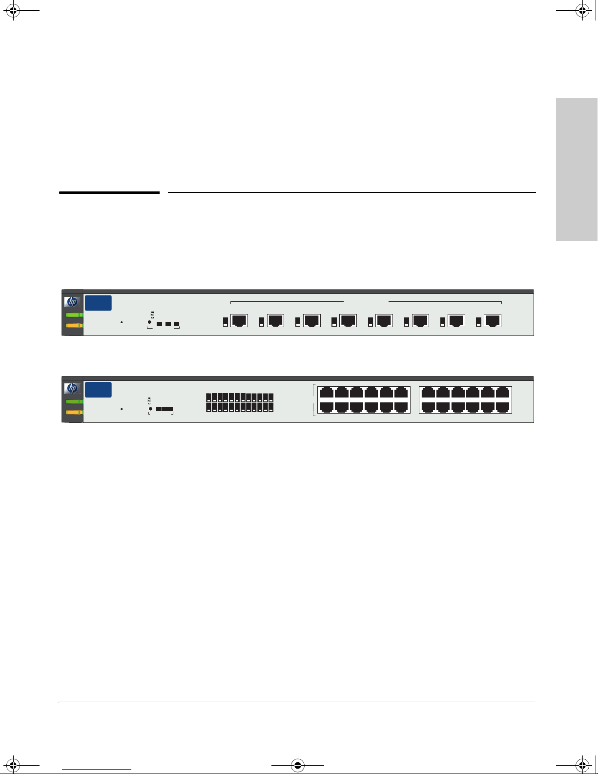
HP Procurve Switch 2708 (HP J4898A)
1
Introducing the HP Procurve
Series 2700 Switches
hp procurve
switch
2708
Power
J4898A
Fault
Reset
Spd mode:
off = 10 Mbps
flash = 100 Mbps
on = 1000 Mbps
Act FDx
Mode LED View
Spd
HP Procurve Switch 2724 (HP J4897A)
hp procurve
switch 2724
Power
J4897A
Fault
Reset Mode LED View
Spd mode:
off = 10 Mbps
flash = 100 Mbps
on = 1000 Mbps
Act FDx
1
Link
Mode
7
Spd
Link
Mode
Throughout this manual, these switches will be abbreviated as the Switch 2708
and the Switch 2724 respectively.
The Switch 2708 has 8 auto-sensing 10/100/1000Base-T RJ-45 ports. The Switch
2724 has 24 auto-sensing 10/100/1000Base-T RJ-45 ports.
These switches are designed to be used primarily to provide Gigabit/second
network speed to the desktop. You can also directly connect servers and
peripherals to these switches and connect them to a network backbone or to
other switches, hubs, or routers.
Link
Mode
2
3456
8
9
1
10 11 12
10/100/1000Base-T Ports
1
13
19
2
2
182417231622152114
10/100/1000Base-T Ports
20
(all ports are IEEE Auto MDI/MDI-X)
3
3
(all ports are IEEE Auto MDI/MDI-X)
4
4
2345 6 131415161718
1
789101112 192021222324
5
5
6
6
7
7
8
8
This chapter describes your HP Series 2700 Switches including:
■ Front and back of the switches
■ Features
■ Switch operation overview
1-1
z3.book Page 2 Friday, November 1, 2002 5:40 PM
Introducing the HP Procurve Series 2700 Switches
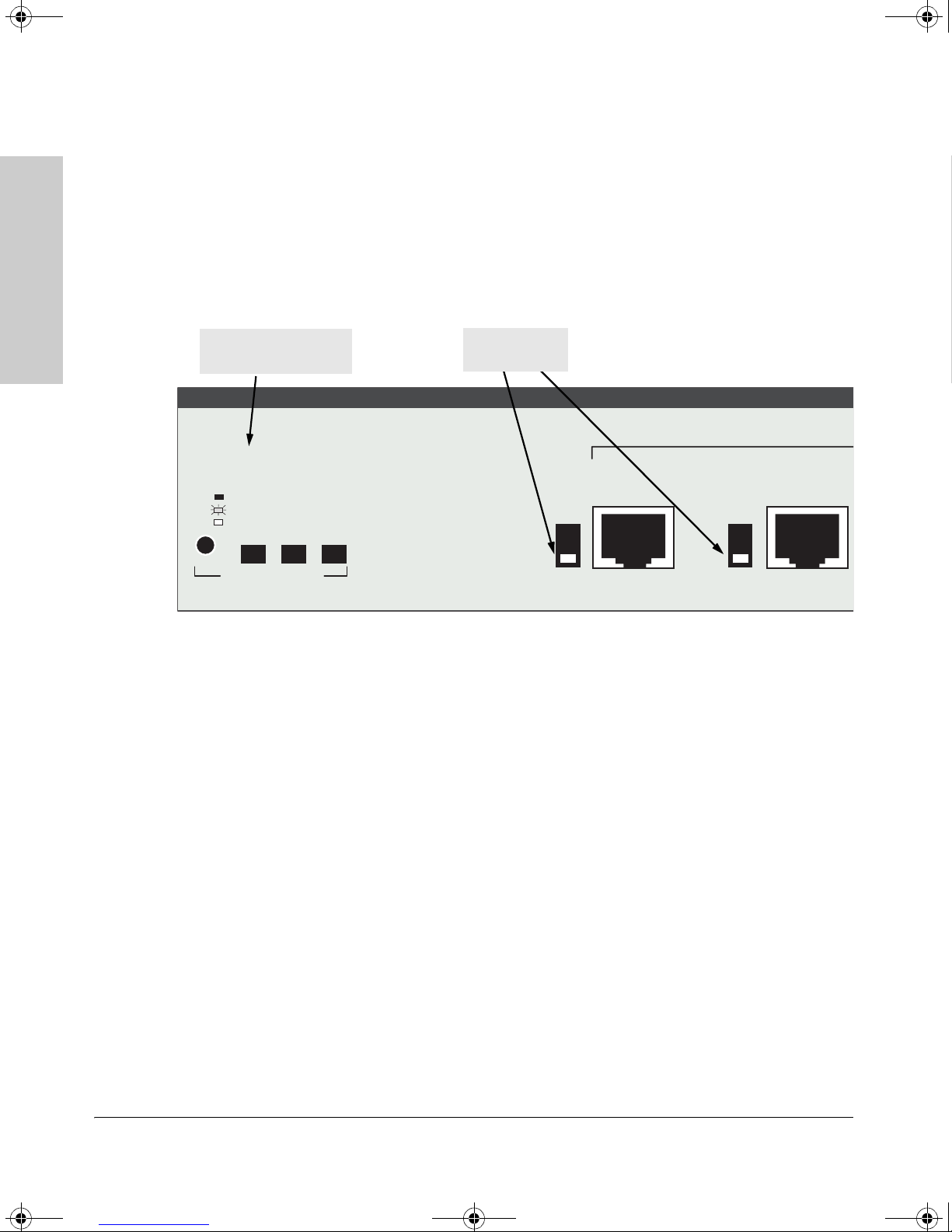
Front of the Switch
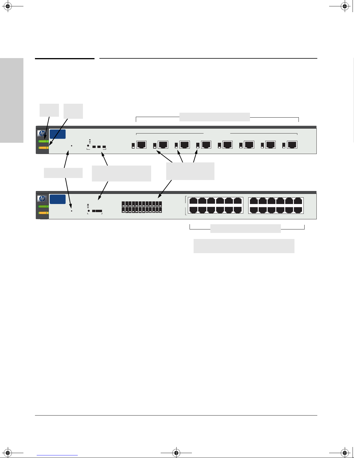
Front of the Switch
hp procurve
2708
switch
J4898A
hp procurve
switch 2724
J4897A
Fault
LED
Spd mode:
off = 10 Mbps
flash = 100 Mbps
on = 1000 Mbps
Reset
Reset Mode LED View
Mode LED View
Spd mode:
off = 10 Mbps
flash = 100 Mbps
on = 1000 Mbps
Act FDx
Act FDx
Spd
Mode
Mode LED View button
and indicator LEDs
1
3456
2
Link
Mode
7
8
9
Spd
Link
Mode
Link
1
10 11 12
10/100/1000Base-T RJ-45 ports
10/100/1000Base-T Ports
1
2
2
3
3
(all ports are IEEE Auto MDI/MDI-X)
4
4
5
5
6
6
7
7
8
8
Link and Mode LEDs
for each port
2345 6 131415161718
1
182417231622152114
13
20
19
10/100/1000Base-T Ports
(all ports are IEEE Auto MDI/MDI-X)
789101112 192021222324
Power
LED
Series 2700 Switches
Introducing the HP Procurve
Power
Fault
Reset button
Power
Fault
10/100/1000Base-T RJ-45 ports
All 10/100/1000Base-T RJ-45 ports have the
IEEE 802.3ab “Auto MDI/MDI-X” feature
1-2
Network Ports
8 auto-sensing 10/100/1000Base-T RJ-45 ports
All these ports have the IEEE 802.3ab “Auto MDI/MDI-X” feature, which
means that you can use either straight-through or crossover twisted-pair
cables to connect any network devices to the switch.
Reset Button
This button is used to reset the switch while it is powered on. This action
executes the switch self test.
z3.book Page 3 Friday, November 1, 2002 5:40 PM
Introducing the HP Procurve Series 2700 Switches
Front of the Switch
LEDs
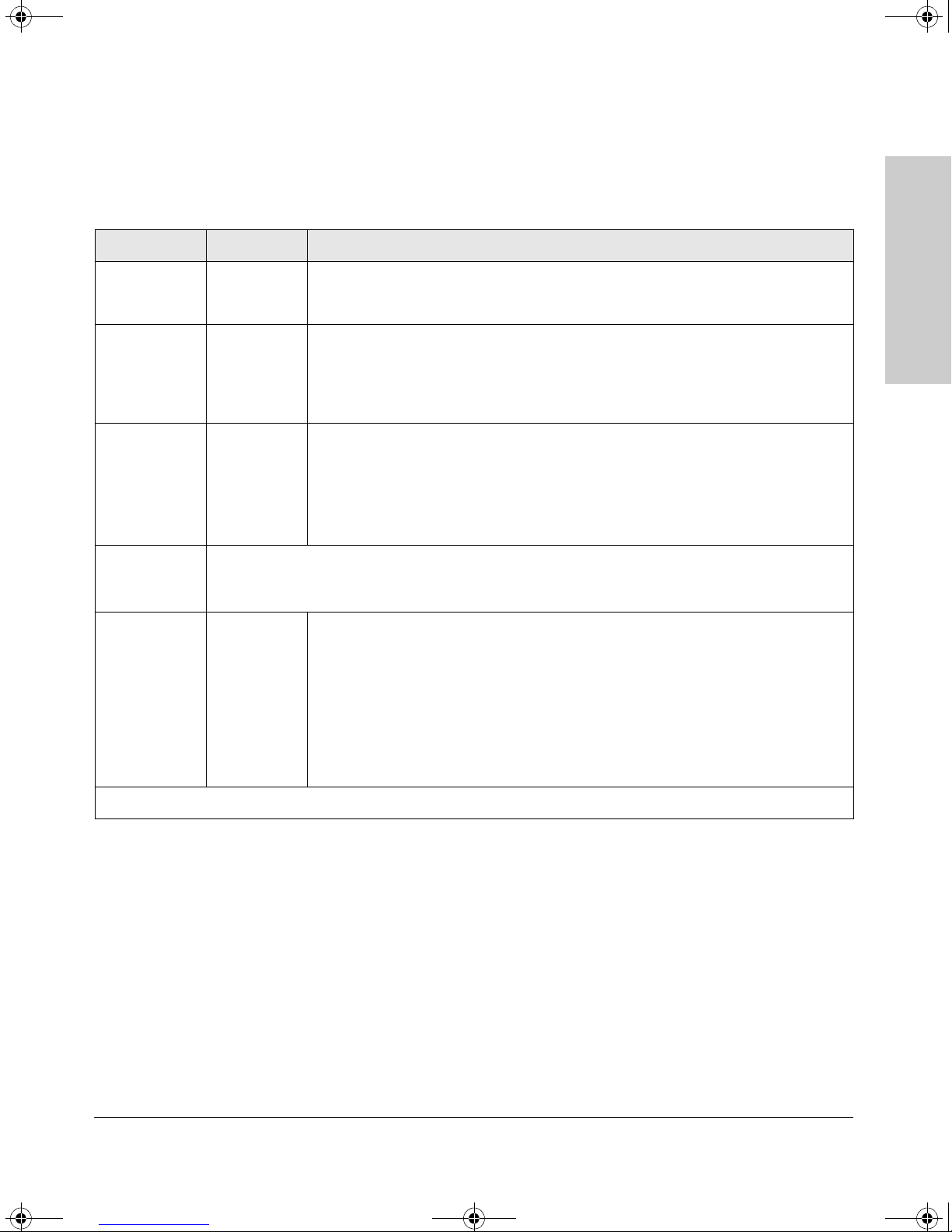
Table 1-1. Switch LEDs
Switch LEDs State Meaning
Power
(green)
Fault
(orange)
Link
(green –
overlaid with
the port
number)
Mode
(green)
On The switch is receiving power.
Off The switch is NOT receiving power.
Off The normal state; indicates that there are no fault conditions on the switch.
On On briefly after the switch is powered on or reset, at the beginning of switch self test.
If on for a prolonged time, the switch has a hardware failure, or has failed its self test.
See chapter 3, “Troubleshooting” for more information.
On Indicates the port is enabled and receiving a link indication from the connected
device.
Off One of these conditions exists:
• no active network cable is connected to the port
• the port is not receiving a link signal
Displays network activity information, or whether the port is configured for full-duplex operation, or
the speed of the connection depending on the mode selected. See “Mode LED View Button and
Indicator LEDs” on the next page for more information.
Introducing the HP Procurve
Series 2700 Switches
Mode LED
View
indicators
(3 green LEDs)
* The flashing behavior is a repeated 1.6 second cycle of two quick flashes followed by an off period.
Act Indicates that the port Mode LEDs are displaying network activity information.
FDx Indicates that the port Mode LEDs are lit for ports that are in Full Duplex Mode.
Spd Indicates that the po rt Mode LEDs are displayi ng the connection speed at which each
port is operating:
• if the port Mode LED is off, the port is operating at 10 Mbps
• if the port Mode LED is flashing*, the port is operating at 100 Mbps
• if the port Mode LED is on continuously, the port is operating at 1000 Mbps
1-3
z3.book Page 4 Friday, November 1, 2002 5:40 PM
Introducing the HP Procurve Series 2700 Switches
Front of the Switch
Mode LED View Button and Indicator LEDs
To optimize the amount of information that can be displayed for each of the
switch ports, the Series 2700 Switches use a Mode LED for each port. The
operation of this LED is controlled by the Mode LED View button, and the
current setting is indicated by the Mode indicator LEDs near the button. Press
the button to change from one mode to the next.
Series 2700 Switches
Introducing the HP Procurve
Mode LED View button
and indicator LEDs
Spd mode:
off = 10 Mbps
flash = 100 Mbps
on = 1000 Mbps
Act FDx
Mode LED View
■ If the Activity (Act) indicator LED is lit, the Mode LED for each port
Spd
Mode LEDs
(one per port)
Link
1
Mode
1
2
2
displays activity information for the port — it flickers as network traffic
is received and transmitted through the port.
■ If the Full Duplex (FDx) indicator LED is lit, the Mode LEDs light for those
ports that are operating in full duplex.
■ If the Speed (Spd) indicator LED is lit, the Mode LEDs behave as follows
to indicate the connection speed for the port:
• Off = 10 Mbps
• Flashing = 100 Mbps (the flashing behavior is a repeated 1.6 sec. cycle
of two quick flashes followed by an off period)
• On = 1000 Mbps
1-4
z3.book Page 5 Friday, November 1, 2002 5:40 PM
Introducing the HP Procurve Series 2700 Switches
Back of the Switch
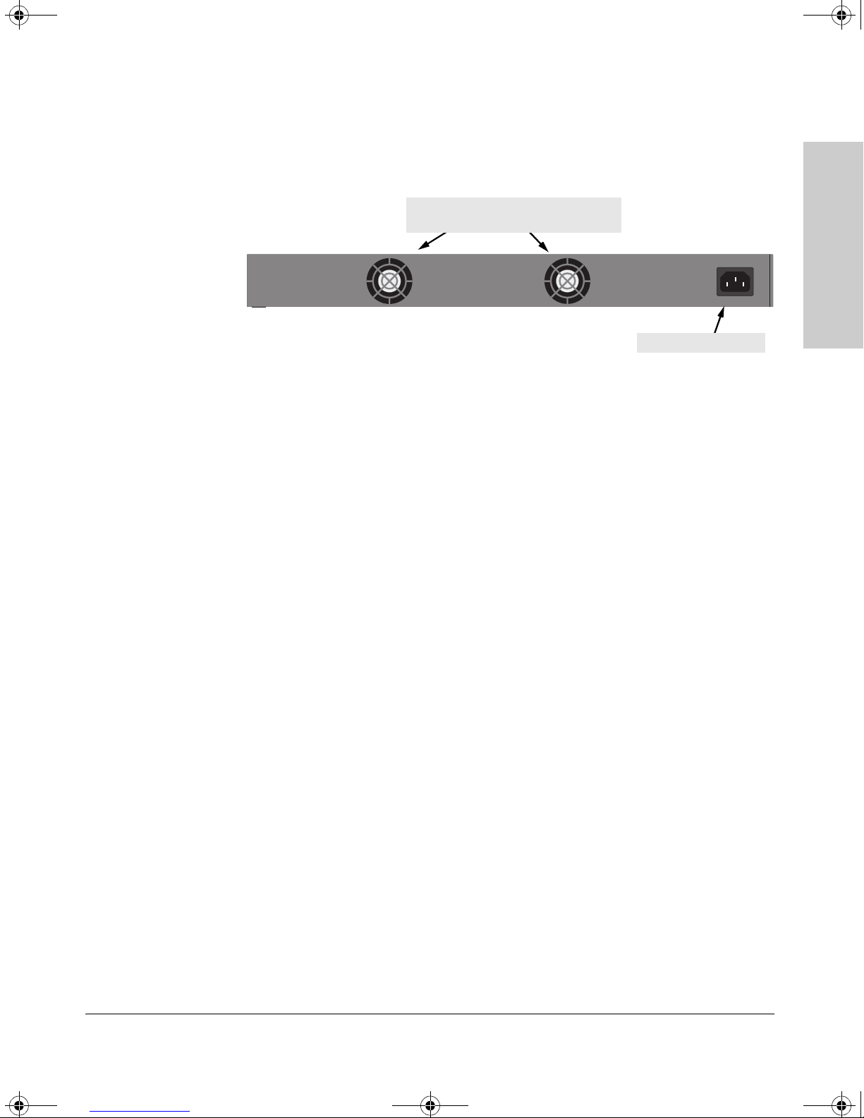
Back of the Switch
cooling vents - make sure these are not
obstructed for proper switch operation
Line: 50/60 Hz.
100-240 V~ 1.5 A (1, 5 A)
AC power connector
Power Connector
The Series 2700 Switches do not have a power switch; they are powered on
when connected to an active AC power source. The switches automatically
adjust to any voltage between 100--240 volts and either 50 or 60 Hz. There are
no voltage range settings required.
Introducing the HP Procurve
Series 2700 Switches
1-5

z3.book Page 6 Friday, November 1, 2002 5:40 PM
Introducing the HP Procurve Series 2700 Switches
Features
Series 2700 Switches
Introducing the HP Procurve
Features
The features of the Series 2700 Switches include:
■ 8 or 24 auto-sensing 10/100/1000Base-T RJ-45 ports.
■ plug-and-play networking — all ports are enabled — just connect the
network cables to active network devices and your switched network is
operational.
■ IEEE 802.3ab “Auto MDI/MDI-X” on all twisted-pair ports, meaning that
all connections can be made using straight-through twisted-pair
cables. Cross-over cables are not required, although they will also work.
Complying with the IEEE 802.3ab standard, the pin operation of each port
is automatically adjusted for the attached device: if the switch detects that
another switch or hub is connected to the port, it configures the port as
MDI; if the switch detects that an end-node device is connected to the
port, it configures the port as MDI-X.
■ automatic learning of the hardware addresses in each switch’s address
forwarding table (the Switch 2708 has an 8000-entry table, the Switch 2724
has a 32,000-entry table).
■ automatically negotiated full-duplex operation for the twisted-pair ports
when connected to other auto-negotiating devices.
■ auto-negotiation of flow control for ports operating at full duplex.
1-6

z3.book Page 7 Friday, November 1, 2002 5:40 PM
Switch Operation Overview
Address Table Operation
Address Learning. As devices are connected to the switch ports, either
directly or through hubs or other switches that are connected to the switch,
the MAC addresses of those devices are learned automatically and stored in
the Series 2700 Switch’s address table. The switch also identifies the number
of the port on which each address is learned so it knows the relative network
location of each device.
Forwarding, Filtering, Flooding. When the switch receives a packet, it
determines the destination address, and looks for the address in the address
table. Based on the port location of that address, the switch then determines
whether to forward, filter-out, or flood the packet.
■ forward - if the destination address is on a different port than the one on
■ filter out - if the destination address is on the same port as the one on
■ flood - whenever a new destination address is found in a packet received
Introducing the HP Procurve Series 2700 Switches
Switch Operation Overview
Introducing the HP Procurve
Series 2700 Switches
which the packet was received, the packet is forwarded to the destination
port and on to the destination device.
which the packet was received, the packet is filtered out. The switch
thereby isolates local traffic so the rest of the network connected to the
switch does not use bandwidth dealing with unnecessary traffic.
on a port, the destination address will not yet be in the switch’s address
table and the Series 2700 Switch cannot know whether to forward or filter
out the packet. In this case, it sends the packet to all the other switch
ports. This is referred to as “flooding”. When the destination device
receives the packet, it replies, and the switch learns the new address from
the reply packet. Then, all future packets destined for that address are
forwarded or filtered out appropriately.
Network Moves and Changes. When devices are moved in the network,
and become connected to a different switch port, the Series 2700 Switch
automatically recognizes the change and updates the address table with the
new port location of the device. Communication with the device is automatically maintained, without any address table manipulation being required.
1-7

z3.book Page 8 Friday, November 1, 2002 5:40 PM

z3.book Page 1 Friday, November 1, 2002 5:40 PM
Installing the Series 2700 Switches
The HP Series 2700 Switches are easy to install. They come with an accessory
kit that includes the brackets for mounting the switch in a standard 19-inch
telco rack or an equipment cabinet, or on a wall, and with rubber feet that can
be attached so the switch can be securely located on a horizontal surface. The
brackets are designed to allow mounting the switch in a variety of orientations.
This chapter shows you how to install your Series 2700 Switches.
2
Installing the Series 2700
Switches
Included Parts
The Series 2700 Switches are shipped with the following components:
■ HP Procurve Series 2700 Switches Installation Guide (5990-3055), this
manual
■ Customer Support/Warranty booklet
■ Accessory kit (5064-2085)
• two mounting brackets
• four 8 mm M4 screws to attach the mounting brackets to the switch
• four 5/8-inch number 12-24 screws to attach the switch to a rack
• four rubber feet
■ Power cord, one of the following:
Australia/New Zealand
China
Continental Europe
Denmark
Japan
Switzerland
United Kingdom/Hong Kong/Singapore
United States/Canada/Mexico
8120-6803
8120-8377
8120-6802
8120-6806
8120-6804
8120-6807
8120-8709
8120-6805
2-1

z3.book Page 2 Friday, November 1, 2002 5:40 PM
Installing the Series 2700 Switches
Installation Procedures
Installation Procedures
Summary
Follow these easy steps to install your switch. The rest of this chapter provides
details on these steps.
1. Prepare the installation site. Make sure that the physical environment
2. Verify that the switch passes its self test. This is a simple process of
into which you will be installing the switch is properly prepared including
having the correct network cabling ready to connect to the switch, and
having a good location for the switch. Please see page 2-3 for some
installation precautions.
plugging the switch into a power source and observing that the LEDs on
the switch’s front panel show correct operation. See page 2-6.
Switches
Installing the Series 2700
3. Mount the switch. The Series 2700 Switches can be mounted in a 19-inch
telco rack or equipment cabinet, on a wall, or on a horizontal surface.
4. Connect power to the switch. Once the switch is mounted, plug it in to
the nearby AC power source.
5. Connect the network devices. Using the appropriate network cables,
connect servers, hubs, other switches, routers, and other network devices
to the switch ports.
At this point, the switch is fully installed and your network should be up and
running. See the rest of this chapter if you need more detailed information on
any of these installation steps.
2-2
 Loading...