

HP Elite 7500MT, Elite 7300MT, Pro 3300MT, Pro 3305MT, Pro 3300 Maintenance And Service Manual

Maintenance & Service Guide
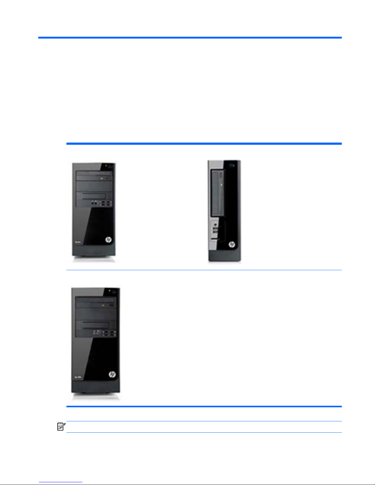
HP Elite 7500 Microtower
HP Elite 7300 Microtower
HP Pro 3300 Microtower
HP Pro 3305 Microtower
HP Pro 3300 Small Form Factor

© Copyright 2011, 2012 Hewlett-Packard
Development Company, L.P. The
information contained herein is subject to
change without notice.
Microsoft and Windows are trademarks of
Microsoft Corporation in the U.S. and other
countries.
The only warranties for HP products and
services are set forth in the express
warranty statements accompanying such
products and services. Nothing herein
should be construed as constituting an
additional warranty. HP shall not be liable
for technical or editorial errors or omissions
contained herein.
This document contains proprietary
information that is protected by copyright.
No part of this document may be
photocopied, reproduced, or translated to
another language without the prior written
consent of Hewlett-Packard Company.
Maintenance & Service Guide
Third Edition (June 2012)
Second Edition (August 2011)
First Edition (June 2011)
Document Part Number: 663321-003

About This Book
WARNING! Text set off in this manner indicates that failure to follow directions could result in bodily
harm or loss of life.
CAUTION: Text set off in this manner indicates that failure to follow directions could result in
damage to equipment or loss of information.
NOTE: Text set off in this manner provides important supplemental information.
iii

iv About This Book

Table of contents
1 Product Features ............................................................................................................................................ 1
Standard Configuration ........................................................................................................................ 1
Serviceability Features ......................................................................................................................... 2
Microtower Components ...................................................................................................................... 2
Small Form Factor Components .......................................................................................................... 3
2 Installing and Customizing the Software ...................................................................................................... 4
Installing the Operating System ........................................................................................................... 4
Downloading Microsoft Windows Updates ........................................................................................... 4
Installing or Upgrading Device Drivers (Windows systems) ................................................................. 5
Accessing Disk Image (ISO) Files ........................................................................................................ 5
Protecting the Software ........................................................................................................................ 5
3 Computer Setup (F10) Utility ......................................................................................................................... 6
Computer Setup (F10) Utilities ............................................................................................................. 6
Using Computer Setup (F10) Utilities .................................................................................. 7
Computer Setup—File ......................................................................................................... 8
Computer Setup—Storage .................................................................................................. 9
Computer Setup—Security ................................................................................................ 11
Computer Setup—Power ................................................................................................... 14
Computer Setup—Advanced ............................................................................................. 15
Recovering the Configuration Settings ............................................................................................... 16
4 Illustrated parts catalog ............................................................................................................................... 17
Microtower (MT) Chassis Spare Parts ............................................................................................... 17
Computer Major Components ............................................................................................ 17
Cables ................................................................................................................................ 21
Misc Parts .......................................................................................................................... 21
Drives ................................................................................................................................. 22
Misc Boards ....................................................................................................................... 23
Sequential Part Number Listing ......................................................................................... 24
v

Small Form Factor (SFF) Chassis Spare Parts .................................................................................. 28
Computer major components ............................................................................................ 28
Cables ................................................................................................................................ 30
Misc Parts .......................................................................................................................... 31
Drives ................................................................................................................................. 33
Misc Boards ....................................................................................................................... 33
Sequential Part Number Listing ......................................................................................... 33
5 Serial ATA (SATA) Drive Guidelines and Features .................................................................................... 36
SATA Hard Drives .............................................................................................................................. 36
SATA Hard Drive Cables .................................................................................................................... 36
SATA Data Cable .............................................................................................................. 36
SMART ATA Drives ............................................................................................................................ 37
Hard Drive Capacities ........................................................................................................................ 37
6 Routine Care, and Disassembly Preparation ............................................................................................. 38
Electrostatic Discharge Information .................................................................................................... 38
Generating Static ............................................................................................................... 38
Preventing Electrostatic Damage to Equipment ................................................................ 39
Personal Grounding Methods and Equipment ................................................................... 39
Grounding the Work Area .................................................................................................. 40
Recommended Materials and Equipment .......................................................................... 40
Operating Guidelines .......................................................................................................................... 41
Routine Care ...................................................................................................................................... 42
General Cleaning Safety Precautions ................................................................................ 42
Cleaning the Computer Case ............................................................................................ 42
Cleaning the Keyboard ...................................................................................................... 42
Cleaning the Monitor .......................................................................................................... 43
Cleaning the Mouse ........................................................................................................... 43
Service Considerations ...................................................................................................................... 43
Power Supply Fan ............................................................................................................. 43
Tools and Software Requirements .................................................................................... 43
Screws ............................................................................................................................... 44
Cables and Connectors ..................................................................................................... 44
Hard Drives ........................................................................................................................ 44
Lithium Coin Cell Battery ................................................................................................... 45
7 Removal and Replacement Procedures Microtower (MT) Chassis .......................................................... 46
Preparation for Disassembly .............................................................................................................. 46
Access Panel ...................................................................................................................................... 47
vi

Front Bezel ......................................................................................................................................... 49
Memory .............................................................................................................................................. 51
DDR3-SDRAM DIMMs ...................................................................................................... 51
Populating DIMM Sockets ................................................................................................. 53
Removing Memory Modules .............................................................................................. 55
Expansion Cards ................................................................................................................................ 58
Cable Management ............................................................................................................................ 65
Cable Connections ............................................................................................................ 66
Drives ................................................................................................................................................. 67
Drive Positions ................................................................................................................... 68
Installing Additional Drives ................................................................................................. 69
System Board Drive Connections ..................................................................... 70
Removing an Optical Drive ............................................................................... 71
Removing a Hard Drive ..................................................................................... 74
Front I/O and USB Panel Housing Assembly ..................................................................................... 81
Power Switch/LED Assembly ............................................................................................................. 84
System Fan ........................................................................................................................................ 86
Fan Sink Assembly ............................................................................................................................. 88
Processor ........................................................................................................................................... 90
Power Supply ..................................................................................................................................... 95
System Board ..................................................................................................................................... 97
Battery ................................................................................................................................................ 99
8 Removal and Replacement Procedures Small Form Factor (SFF) Chassis .......................................... 101
Preparation for Disassembly ............................................................................................................ 101
Access Panel .................................................................................................................................... 102
Front Bezel ....................................................................................................................................... 104
Memory ............................................................................................................................................ 105
DDR3-SDRAM DIMMs .................................................................................................... 105
Populating DIMM Sockets ............................................................................................... 106
Removing DIMMs ............................................................................................................ 107
Expansion Card ................................................................................................................................ 110
Cable Management .......................................................................................................................... 115
Cable Connections .......................................................................................................... 116
Drives ............................................................................................................................................... 117
Drive Positions ................................................................................................................. 117
Removing Drives ............................................................................................................. 118
Removing an Optical Drive ............................................................................. 118
Removing the Hard Drive ................................................................................ 120
Power Switch .................................................................................................................................... 124
Front USB Assembly ........................................................................................................................ 126
vii

Fan Assembly ................................................................................................................................... 129
Fan Sink ........................................................................................................................................... 131
Processor ......................................................................................................................................... 133
Power Supply ................................................................................................................................... 135
System Board ................................................................................................................................... 137
Battery .............................................................................................................................................. 139
Appendix A Connector Pin Assignments .................................................................................................... 141
Ethernet BNC ................................................................................................................................... 141
USB .................................................................................................................................................. 141
Microphone ....................................................................................................................................... 141
Headphone ....................................................................................................................................... 142
Line-in Audio .................................................................................................................................... 142
Line-out Audio .................................................................................................................................. 142
4-Pin Power (for CPU) ...................................................................................................................... 142
Monitor ............................................................................................................................................. 143
Serial Interface, Powered and Non-Powered ................................................................................... 143
DVI Connector .................................................................................................................................. 144
24-Pin Power .................................................................................................................................... 145
PCI Express ..................................................................................................................................... 146
PCI Express ..................................................................................................................................... 147
Appendix B Power Cord Set Requirements ................................................................................................ 148
General Requirements ..................................................................................................................... 148
Japanese Power Cord Requirements .............................................................................................. 148
Country-Specific Requirements ........................................................................................................ 149
Appendix C POST Error Messages .............................................................................................................. 150
POST Numeric Codes and Text Messages ..................................................................................... 151
Interpreting POST Diagnostic Front Panel LEDs and Audible Codes .............................................. 159
Appendix D Troubleshooting Without Diagnostics .................................................................................... 163
Safety and Comfort .......................................................................................................................... 163
Before You Call for Technical Support ............................................................................................. 163
Helpful Hints ..................................................................................................................................... 164
Solving General Problems ................................................................................................................ 166
Solving Power Problems .................................................................................................................. 169
Solving Diskette Problems ............................................................................................................... 170
Solving Hard Drive Problems ........................................................................................................... 173
Solving Media Card Reader Problems ............................................................................................. 176
viii

Solving Display Problems ................................................................................................................. 178
Solving Audio Problems ................................................................................................................... 182
Solving Printer Problems .................................................................................................................. 184
Solving Keyboard and Mouse Problems .......................................................................................... 185
Solving Hardware Installation Problems ........................................................................................... 187
Solving Network Problems ............................................................................................................... 188
Solving Memory Problems ............................................................................................................... 192
Solving Processor Problems ............................................................................................................ 193
Solving CD-ROM and DVD Problems .............................................................................................. 194
Solving USB Flash Drive Problems .................................................................................................. 196
Solving Front Panel Component Problems ...................................................................................... 197
Solving Internet Access Problems .................................................................................................... 197
Solving Software Problems .............................................................................................................. 200
Contacting Customer Support .......................................................................................................... 201
Appendix E Password Security and Resetting CMOS ............................................................................... 202
Resetting the Password Jumper – Models 3300/3305 ..................................................................... 203
Resetting the Password Jumper – Model 7300/7500 ....................................................................... 204
Clearing and Resetting the CMOS – Models 3300/3305 ................................................................. 205
Clearing and Resetting the CMOS – Model 7300/7500 ................................................................... 206
Appendix F Backup and Recovery ............................................................................................................... 207
Windows 7 – Backup and Recovery ................................................................................................. 207
Backing Up Your Information ........................................................................................... 207
Performing a Recovery .................................................................................................... 209
Using the Windows Recovery Tools ............................................................... 209
Using F11 ........................................................................................................ 210
Using a Windows 7 Operating System DVD (purchased separately) ............. 210
Windows Vista – Backup and Recovery ........................................................................................... 211
Backing Up Your Information ........................................................................................... 211
Performing a Recovery .................................................................................................... 212
Using the Windows Recovery Tools ............................................................... 213
Using F11 ........................................................................................................ 213
Using a Windows Vista Operating System DVD (purchased separately) ....... 214
Appendix G Specifications ........................................................................................................................... 215
MT Specifications ............................................................................................................................. 215
SFF Specifications ........................................................................................................................... 216
Index ................................................................................................................................................................. 217
ix

x
1 Product Features
Standard Configuration
HP Pro 3300 MT HP Pro 3300 SFF
HP Elite 7500/7300 MT
NOTE: The drive configuration shown above may be different than your computer model.
Standard Configuration 1
Serviceability Features
The computers include features that make them easy to upgrade and service. A Torx T-15 or flat
blade screwdriver is needed for many of the installation procedures described in this guide.
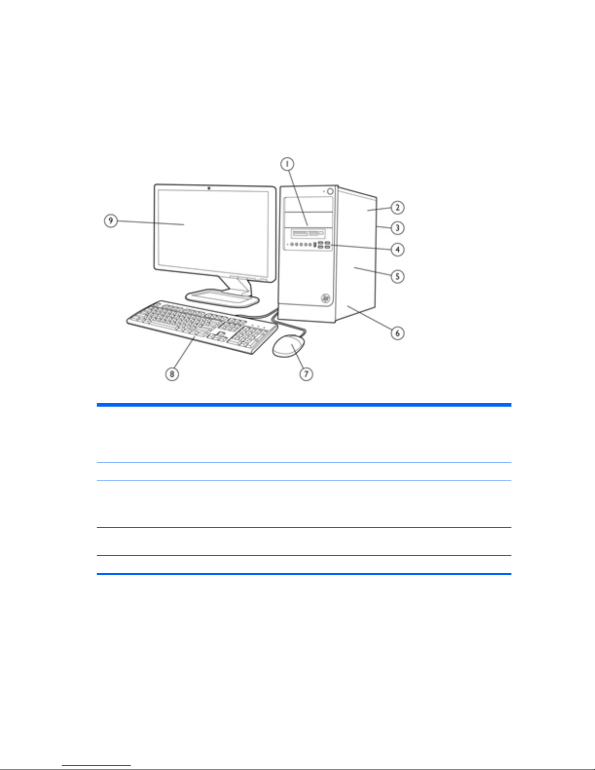
Microtower Components
Table 1-1 Microtower Components
1 (2) external 5.25” drive bays for optional optical
drives
(1) external 3.5” drive bay for optional media
reader
6 (3) PCIe x1 slots, (1) PCIe x16 slot, (1) miniPCI
slot
2 Power Supply 7 USB Scroll Mouse
3 Rear I/O includes: (4) USB 2.0 ports, SPDIF out,
RJ-45 network interface, DVI-D and VGA video
interfaces, microphone jack, audio in/out jacks,
5.1/7.1 channel audio jacks*
1
8 HP USB Standard Value Keyboard
4 Front I/O includes: (4) USB 2.0 ports, dedicated
headphone output, microphone jack
9 Monitor (sold separately)
5 (2) internal 3.5” hard drive bays
1
HP Pro 3300 supports 5.1 channel audio, HP Pro 3305 supports 7.1 channel audio
2 Chapter 1 Product Features
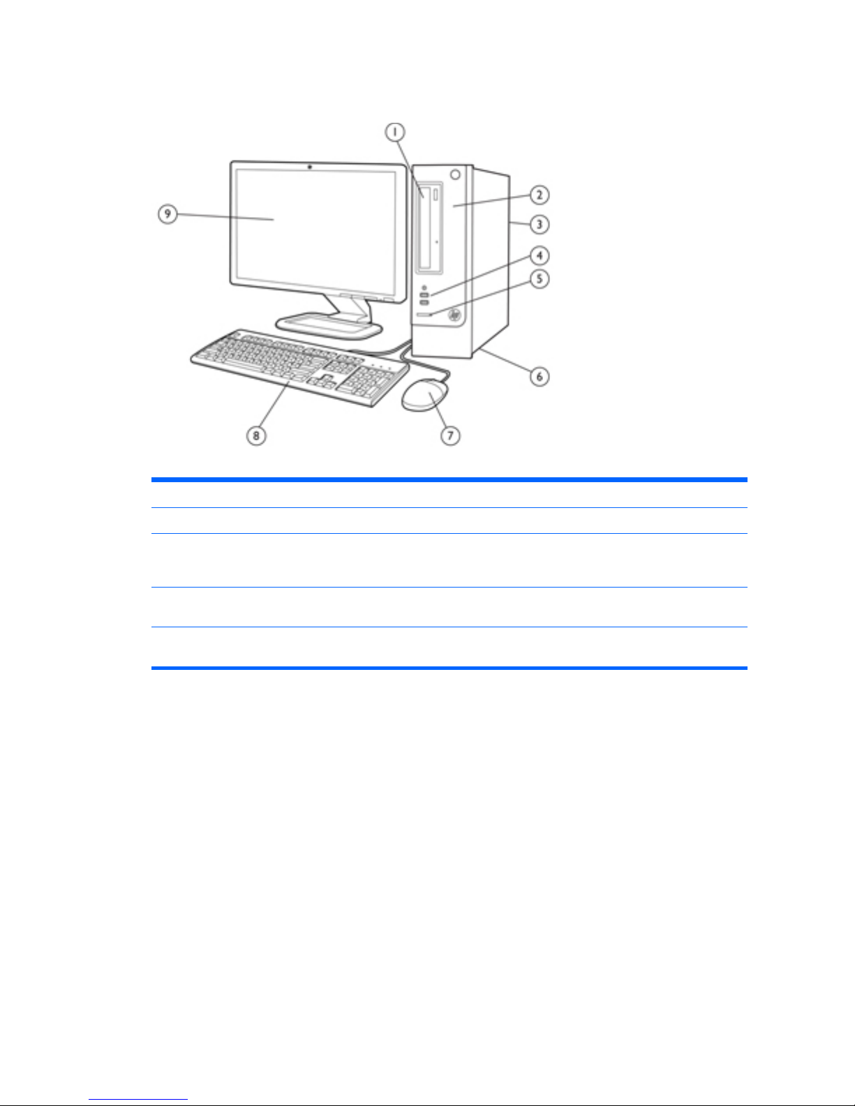
Small Form Factor Components
Table 1-2 Microtower Components
1 External 5.25” drive bay for optical drive 6 Power Supply
2 Internal 3.5” hard drive bay 7 USB Scroll Mouse
3 Rear I/O includes: (3) PCIe x1 slots, (1) PCIe x16
slot, (2) miniPCI slots USB 2.0 ports; network,
DVI-D and VGA video ports, and audio
8 HP USB Standard Value Keyboard
4 Front I/O includes: (2) USB 2.0 ports, dedicated
headphone output
9 Monitor (sold separately)
5 HP 6-in-1 Media Card Reader HP Pro 3300 supports 5.1 channel audio, HP Pro
3305 supports 7.1 channel audio
Small Form Factor Components 3

2 Installing and Customizing the
Software
If your computer was not shipped with a Microsoft operating system, some portions of this
documentation do not apply. Additional information is available in online help after you install the
operating system.
NOTE: If the computer was shipped with Windows 7 loaded, you will be prompted to register the
computer with HP Total Care before installing the operating system. You will see a brief movie
followed by an online registration form. Fill out the form, click the Begin button, and follow the
instructions on the screen.
CAUTION: Do not add optional hardware or third-party devices to the computer until the operating
system is successfully installed. Doing so may cause errors and prevent the operating system from
installing properly.
NOTE: Be sure there is a 10.2-cm (4-inch) clearance at the back of the unit and above the monitor
to permit the required airflow.
Installing the Operating System
The first time you turn on the computer, the operating system is installed automatically. This process
takes about 5 to 10 minutes, depending on which operating system is being installed. Carefully read
and follow the instructions on the screen to complete the installation.
CAUTION: Once the automatic installation has begun, DO NOT TURN OFF THE COMPUTER
UNTIL THE PROCESS IS COMPLETE. Turning off the computer during the installation process may
damage the software that runs the computer or prevent its proper installation.
NOTE: If the computer shipped with more than one operating system language on the hard drive,
the installation process could take up to 60 minutes.
If your computer was not shipped with a Microsoft operating system, some portions of this
documentation do not apply. Additional information is available in online help after you install the
operating system.
Downloading Microsoft Windows Updates
1. To set up your Internet connection, click Start > Internet Explorer and follow the instructions on
the screen.
2. Once an Internet connection has been established, click the Start button.
4 Chapter 2 Installing and Customizing the Software

3. Select the All Programs menu.
4. Click on the Windows Update link.
In Windows 7, the Windows Update screen appears. Click view available updates and make
sure all critical updates are selected. Click the Install button and follow the instructions on the
screen.
In Windows XP, you will be directed to the Microsoft Windows Update Web site. If you see
one or more pop-up windows that ask you to install a program from
http://www.microsoft.com,
click Yes to install the program. Follow the instructions on the Microsoft Web site to scan for
updates and install critical updates and service packs.
It is recommended that you install all of the critical updates and service packs.
5. After the updates have been installed, Windows will prompt you to reboot the machine. Be sure
to save any files or documents that you may have open before rebooting. Then select Yes to
reboot the machine.
Installing or Upgrading Device Drivers (Windows
systems)
When installing optional hardware devices after the operating system installation is complete, you
must also install the drivers for each of the devices.
If prompted for the i386 directory, replace the path specification with C:\i386, or use the Browse
button in the dialog box to locate the i386 folder. This action points the operating system to the
appropriate drivers.
Obtain the latest support software, including support software for the operating system from
http://www.hp.com/support. Select your country and language, select Download drivers and
software (and firmware), enter the model number of the computer, and press Enter.
Accessing Disk Image (ISO) Files
There are disk image files (ISO files) included on your PC that contain the installation software for
additional software. These CD image files are located in the folder C:\SWSetup\ISOs. Each .iso file
can be burned to CD media to create an installation CD. It is recommended that these disks be
created and the software installed in order to get the most from your PC. The software and image file
names are:
●
Corel WinDVD SD and BD – installation software for WinDVD – used to play DVD movies
● HP Insight Diagnostics OR Vision Diagnostics – software to perform diagnostic activities on your
PC
Protecting the Software
To protect the software from loss or damage, keep a backup copy of all system software,
applications, and related files stored on the hard drive. Refer to the operating system or backup utility
documentation for instructions on making backup copies of your data files.
Installing or Upgrading Device Drivers (Windows systems) 5

3 Computer Setup (F10) Utility
Computer Setup (F10) Utilities
Use Computer Setup (F10) Utility to do the following:
●
Change factory default settings.
●
Set the system date and time.
● Set, view, change, or verify the system configuration, including settings for processor, graphics,
memory, audio, storage, communications, and input devices.
●
Modify the boot order of bootable devices such as hard drives, optical drives, or USB flash
media devices.
●
Enable Quick Boot, which is faster than Full Boot but does not run all of the diagnostic tests run
during a Full Boot. You can set the system to:
❑
always Quick Boot (default);
❑
periodically Full Boot (from every 1 to 30 days); or
❑
always Full Boot.
● Select Post Messages Enabled or Disabled to change the display status of Power-On Self-Test
(POST) messages. Post Messages Disabled suppresses most POST messages, such as
memory count, product name, and other non-error text messages. If a POST error occurs, the
error is displayed regardless of the mode selected. To manually switch to Post Messages
Enabled during POST, press any key (except F1 through F12).
●
Establish an Ownership Tag, the text of which is displayed each time the system is turned on or
restarted.
●
Enter the Asset Tag or property identification number assigned by the company to this computer.
●
Enable the power-on password prompt during system restarts (warm boots) as well as during
power-on.
●
Establish a setup password that controls access to the Computer Setup (F10) Utility and the
settings described in this section.
●
Secure integrated I/O functionality, including the serial, USB, or parallel ports, audio, or
embedded NIC, so that they cannot be used until they are unsecured.
●
Enable or disable removable media boot ability.
6 Chapter 3 Computer Setup (F10) Utility

●
Solve system configuration errors detected but not automatically fixed during the Power-On SelfTest (POST).
●
Replicate the system setup by saving system configuration information on a USB device and
restoring it on one or more computers.
●
Execute self-tests on a specified ATA hard drive (when supported by drive).
●
Enable or disable DriveLock security (when supported by drive).
Using Computer Setup (F10) Utilities
Computer Setup can be accessed only by turning the computer on or restarting the system.
To access the Computer Setup Utilities menu, complete the following steps:
1. Turn on or restart the computer. If you are in Microsoft Windows, click Start > Shut Down >
Restart.
2. Press either Esc or F10 while the “Press the ESC key for Startup Menu” message is displayed at
the bottom of the screen.
Pressing Esc displays a menu that allows you to access different options available at startup.
NOTE: If you do not press Esc or F10 at the appropriate time, you must restart the computer
and again press Esc or F10 when the monitor light turns green to access the utility.
3. If you pressed Esc, press F10 to enter Computer Setup.
4. A choice of five headings appears in the Computer Setup Utilities menu: File, Storage, Security,
Power, and Advanced.
5. Use the arrow (left and right) keys to select the appropriate heading. Use the arrow (up and
down) keys to select the option you want, then press Enter. To return to the Computer Setup
Utilities menu, press Esc.
6. To apply and save changes, select File > Save Changes and Exit.
●
If you have made changes that you do not want applied, select Ignore Changes and Exit.
●
To reset to factory settings or previously saved default settings (some models), select
Apply Defaults and Exit. This option will restore the original factory system defaults.
CAUTION: Do NOT turn the computer power OFF while the BIOS is saving the Computer Setup
(F10) changes because the CMOS could become corrupted. It is safe to turn off the computer only
after exiting the F10 Setup screen.
Table 3-1 Computer Setup (F10) Utility
Heading Table
File
Computer Setup—File on page 8
Storage
Computer Setup—Storage on page 9
Security
Computer Setup—Security on page 11
Power
Computer Setup—Power on page 14
Advanced
Computer Setup—Advanced on page 15
Computer Setup (F10) Utilities 7

Computer Setup—File
NOTE: Support for specific Computer Setup options may vary depending on the hardware
configuration.
Table 3-2 Computer Setup—File
Option Description
System Information Lists:
●
Product name
●
SKU number (some models)
● Processor type/speed/stepping
● Cache size (L1/L2/L3) (dual core processors have this listed twice)
●
Installed memory size/speed, number of channels (single or dual) (if applicable)
●
Integrated MAC address for embedded, enabled NIC (if applicable)
● System BIOS (includes family name and version)
●
Chassis serial number
●
Asset tracking number
About Displays copyright notice.
Set Time and Date Allows you to set system time and date.
Apply Defaults and
Exit
Applies the currently selected default settings and clears any established passwords.
Ignore Changes
and Exit
Exits Computer Setup without applying or saving any changes.
Save Changes and
Exit
Saves changes to system configuration or default settings and exits Computer Setup.
8 Chapter 3 Computer Setup (F10) Utility

Computer Setup—Storage
NOTE: Support for specific Computer Setup options may vary depending on the hardware
configuration.
Table 3-3 Computer Setup—Storage
Option Description
Device Configuration Lists all installed BIOS-controlled storage devices.
When a device is selected, detailed information and options are displayed. The following options
may be presented:
CD-ROM: Model, firmware version, serial number.
Hard Disk: Size, model, firmware version, serial number.
● SMART (ATA disks only)
●
Translation mode (ATA disks only)
●
Connector color(ATA disks only)
Lets you select the translation mode to be used for the device. This enables the BIOS to
access disks partitioned and formatted on other systems and may be necessary for users of
older versions of UNIX (e.g., SCO UNIX version 3.2). Options are Automatic, Bit-Shift,
LBA Assisted, User, and Off.
Available only when the drive translation mode is set to User, allows you to specify the
parameters (logical cylinders, heads, and sectors per track) used by the BIOS to translate
disk I/O requests (from the operating system or an application) into terms the hard drive can
accept. Logical cylinders may not exceed 1024. The number of heads may not exceed 256.
The number of sectors per track may not exceed 63.
CAUTION: Ordinarily, the translation mode selected automatically by the BIOS should not
be changed. If the selected translation mode is not compatible with the translation mode that
was active when the disk was partitioned and formatted, the data on the disk will be
inaccessible.
Diskette: Model and firmware version.
NOTE: Displays for USB diskette drives.
Default Values (ATA disks only)
SATA Defaults
See Translation Mode above for details.
Storage Options SATA Emulation
Allows you to choose how the SATA controller and devices are accessed by the operating
system. There are two supported options: IDE and AHCI (default).
IDE - This is the most backwards-compatible setting of the three options. Operating systems
usually do not require additional driver support in IDE mode.
AHCI (default option) - Allows operating systems with AHCI device drivers loaded to take
advantage of more advanced features of the SATA controller.
NOTE: The RAID/AHCI device driver must be installed prior to attempting to boot from a RAID/
AHCI volume. If you attempt to boot from a RAID/AHCI volume without the required device driver
installed, the system will crash (blue screen). RAID volumes may become corrupted if they are
booted to after disabling RAID.
Computer Setup (F10) Utilities 9

Table 3-3 Computer Setup—Storage (continued)
DPS Self-Test Allows you to execute self-tests on ATA hard drives capable of performing the Drive Protection
System (DPS) self-tests.
NOTE: This selection will only appear when at least one drive capable of performing the DPS
self-tests is attached to the system.
Boot Order Allows you to:
● Specify the order in which EFI boot sources (such as a internal hard drive, USB hard drive,
USB optical drive, or internal optical drive) are checked for a bootable operating system
image. Each device on the list may be individually excluded from or included for
consideration as a bootable operating system source.
EFI boot sources always have precedence over legacy boot sources.
●
Specify the order in which legacy boot sources (such as a network interface card, internal
hard drive, USB optical drive, or internal optical drive) are checked for a bootable operating
system image. Each device on the list may be individually excluded from or included for
consideration as a bootable operating system source.
●
Specify the order of attached hard drives. The first hard drive in the order will have priority in
the boot sequence and will be recognized as drive C (if any devices are attached).
NOTE: You can use F5 to disable individual boot items, as well as disable EFI boot and/or
legacy boot.
NOTE: MS-DOS drive lettering assignments may not apply after a non-MS-DOS operating
system has started.
Shortcut to Temporarily Override Boot Order
To boot one time from a device other than the default device specified in Boot Order, restart the
computer and press Esc (to access the boot menu) and then F9 (Boot Order), or only F9 (skipping
the boot menu) when the monitor light turns green. After POST is completed, a list of bootable
devices is displayed. Use the arrow keys to select the preferred bootable device and press Enter.
The computer then boots from the selected non-default device for this one time.
10 Chapter 3 Computer Setup (F10) Utility

Computer Setup—Security
NOTE: Support for specific Computer Setup options may vary depending on the hardware
configuration.
Table 3-4 Computer Setup—Security
Option Description
Setup Password Allows you to set and enable a setup (administrator) password.
NOTE: If the setup password is set, it is required to change Computer Setup options, flash the
ROM, and make changes to certain plug and play settings under Windows.
NOTE: This selection will only appear when at least one drive that supports the DriveLock
feature is attached to the system.
See the Desktop Management Guide for more information.
Power-On Password Allows you to set and enable a power-on password. The power-on password prompt appears
after a power cycle. If the user does not enter the correct power-on password, the unit will not
boot.
NOTE: This selection will only appear when at least one drive that supports the DriveLock
feature is attached to the system.
See the Desktop Management Guide for more information.
Password Options
(This selection appears
only if a power-on
password or setup
password is set.)
Allows you to enable/disable:
●
Lock Legacy Resources (appears if a setup password is set). Default is enabled.
●
Setup Browse Mode (appears if a setup password is set) (allows viewing, but not changing,
the F10 Setup Options without entering setup password). Default is enabled.
●
Password prompt on F9, F11, & F12 (allows access to menus without entering setup
password). Default is enabled.
●
Network Server Mode (appears if a power-on password is set). Default is disabled.
See the Desktop Management Guide for more information.
Device Security Allows you to set Device Available/Device Hidden (default is Device Available) for:
●
Embedded security device (some models)
●
System audio
● Serial ports (some models)
●
Parallel port (some models)
●
Network controller
NOTE: You must disable AMT before trying to hide the network controller.
●
SATA0
● SATA1
●
SATA2
Computer Setup (F10) Utilities 11

Table 3-4 Computer Setup—Security (continued)
USB Security Allows you to set Enabled/Disabled (default is Enabled) for:
● Front USB Ports
◦ USB Port 1
◦ USB Port 2
◦
USB Port 3
◦
USB Port 4
●
Rear USB Ports
◦
USB Port 8
◦ USB Port 9
◦
USB Port 10
◦
USB Port 11
● Internal USB Ports
◦
USB Port 0
◦
USB Port 5 (some models)
Slot Security Allows you to disable anyPCI Express or MiniCard slot. Default is enabled.
Network Boot Enables/disables the computer’s ability to boot from an operating system installed on a network
server. (Feature available on NIC models only; the network controller must be either a PCI
expansion card or embedded on the system board.) Default is enabled.
System IDs Allows you to view:
● Product Name
● Serial number
● Universal Unique Identifier (UUID) number. The UUID can only be updated if the current
chassis serial number is invalid. (These ID numbers are normally set in the factory and are
used to uniquely identify the system.)
●
SKU Number
●
Family Name
● Asset tag (18-byte identifier), a property identification number assigned by the company to
the computer.
● Feature Byte
● Build ID
● Keyboard locale setting for System ID entry
12 Chapter 3 Computer Setup (F10) Utility

Table 3-4 Computer Setup—Security (continued)
System Security
(some models: these
options are hardware
dependent)
Data Execution Prevention (enable/disable) - Helps prevent operating system security breaches.
Default is enabled.
Virtualization Technology (VTx/VTd)(some models) (enable/disable) - Controls the virtualization
features of the processor and DMA remapping features of the chipset. Changing this setting
requires turning the computer off and then back on. Default is disabled.
Intel TXT (LT) Support (some models) (enable/disable) - Controls the underlying processor and
chipset features needed to support a virtual appliance. Changing this setting requires turning the
computer off and then back on. Default is disabled. To enable this feature you must enable the
following features:
●
Embedded Security Device Support
●
Virtualization Technology
●
Virtualization Technology Directed I/O
Embedded Security Device Support (some models) (enable/disable) - Permits activation and
deactivation of the Embedded Security Device. Changing this setting requires turning the
computer off and then back on.
NOTE: To configure the Embedded Security Device, a Setup password must be set.
●
Reset to Factory Settings (some models) (Do not reset/Reset) - Resetting to factory defaults
will erase all security keys. Changing this setting requires turning the computer off and then
back on. Default is Do not reset.
CAUTION: The embedded security device is a critical component of many security
schemes. Erasing the security keys will prevent access to data protected by the Embedded
Security Device. Choosing Reset to Factory Settings may result in significant data loss.
OS management of Embedded Security Device (some models) (enable/disable) - This option
allows the user to limit operating system control of the Embedded Security Device. Changing this
setting requires turning the computer off and then back on. This option allows the user to limit OS
control of the Embedded Security Device. Default is enabled.
Reset of Embedded Security Device through OS (some models) (enable/disable) - This option
allows the user to limit the operating system ability to request a Reset to Factory Settings of the
Embedded Security Device. Changing this setting requires turning the computer off and then back
on. Default is disabled.
NOTE: To enable this option, a Setup password must be set.
Computer Setup (F10) Utilities 13

Computer Setup—Power
NOTE: Support for specific Computer Setup options may vary depending on the hardware
configuration.
Table 3-5 Computer Setup—Power
Option Description
OS Power
Management (some
models)
● Runtime Power Management— Enable/Disable. Allows certain operating systems to reduce
processor voltage and frequency when the current software load does not require the full
capabilities of the processor. Default is enabled.
● Idle Power Savings—Extended/Normal. Allows certain operating systems to decrease the
processors power consumption when the processor is idle. Default is extended.
●
Unique Sleep State Blink Rates—Enable/Disable. This feature is designed to provide a
visual indication of what sleep state the system is in. Each sleep state has a unique blink
pattern. Default is disabled.
◦
S0 (On) = Solid green LED.
◦ S3 (Stand By)= 3 blinks at 1Hz (50% duty cycle) followed by a pause of 2 seconds
(green LED) — repeated cycles of 3 blinks and a pause.
◦
S4 (Hibernation)= 4 blinks at 1Hz (50% duty cycle) followed by a pause of 2 seconds
(green LED) — repeated cycles of 4 blinks and a pause.
◦ S5 (Soft Off) = LED is off.
NOTE: If this feature is disabled, S4 and S5 both have the LED off. S1 (no longer
supported) and S3 use 1 blink per second.
Hardware Power
Management
SATA Power Management – Enables or disables SATA bus and/or device power management.
Default is enabled.
S5 Maximum Power Savings – Turns off power to all nonessential hardware when system is off to
meet EUP Lot 6 requirement of less than 1 Watt power usage. Default is disabled.
S5 Wake on LAN (enable/disable).
●
To disable Wake on LAN during the off state (S5), use the arrow (left and right) keys to
select the Advanced > Device Options menu and set the S5 Wake on LAN feature to
Disable. This obtains the lowest power consumption available on the computer during S5. It
does not affect the ability of the computer to Wake on LAN from suspend or hibernation, but
will prevent it from waking from S5 via the network. It does not affect operation of the
network connection while the computer is on.
●
If a network connection is not required, completely disable the network controller (NIC) by
using the arrow (left and right) keys to select the Security > Device Security menu. Set the
Network Controller option to Device Hidden. This prevents the network controller from being
used by the operating system and reduces the power used by the computer in S5.
Thermal CPU Fan Speed (view only) – Lets you view fan speed.
System Fan Speed (view only) – Lets you view fan speed.
14 Chapter 3 Computer Setup (F10) Utility

Computer Setup—Advanced
NOTE: Support for specific Computer Setup options may vary depending on the hardware
configuration.
Table 3-6 Computer Setup—Advanced (for advanced users)
Option Heading
Power-On Options Allows you to set:
● POST messages (enable/disable). Default is disabled.
●
After Power Loss (off/on/previous state). Default is Power off. Setting this option to:
◦
Power off—causes the computer to remain powered off when power is restored.
◦ Power on—causes the computer to power on automatically as soon as power is
restored.
◦
Previous state—causes the computer to power on automatically as soon as power is
restored, if it was on when power was lost.
NOTE: If you turn off power to the computer using the switch on a power strip, you will not be
able to use the suspend/sleep feature or the Remote Management features.
● POST Delay (in seconds). Enabling this feature will add a user-specified delay to the POST
process. This delay is sometimes needed for hard disks on some PCI cards that spin up very
slowly, so slowly that they are not ready to boot by the time POST is finished. The POST
delay also gives you more time to select F10 to enter Computer (F10) Setup. Default is
None.
BIOS Power-On Allows you to set the computer to turn on automatically at a time you specify.
Bus Options On some models, allows you to enable or disable:
● PCI SERR# Generation. Default is enabled.
●
PCI VGA Palette Snooping, which sets the VGA palette snooping bit in PCI configuration
space; only needed when more than one graphics controller is installed. Default is disabled.
Device Options Allows you to set:
●
Num Lock State at Power-On (off/on). Default is off.
●
Integrated Video (enable/disable). Use this option to disable the integrated video controller
when another video controller is present in the system. Default is enabled.
●
Multi-Processor (enable/disable). Use this option to disable multi-processor support under
the OS. Default is enabled.
●
Hyper-threading (enable/disable) (some models). Use this option to disable processor hyperthreading.
●
NIC Option ROM Download (PXE, iSCSI, disabled). The BIOS contains an embedded NIC
option ROM to allow the unit to boot through the network to a PXE server. This is typically
used to download a corporate image to a hard drive. The NIC option ROM takes up memory
space below 1MB commonly referred to as DOS Compatibility Hole (DCH) space. This
space is limited. This F10 option will allow users to disable the downloading of this
embedded NIC option ROM thus giving more DCH space for additional PCI cards which may
need option ROM space. The default will be to have the NIC option-ROM-enabled. Default is
PXE.
Computer Setup (F10) Utilities 15

Table 3-6 Computer Setup—Advanced (for advanced users) (continued)
VGA Configuration Displayed only if there is an add-in video card in the system. Allows you to specify which VGA
controller will be the “boot” or primary VGA controller.
AMT Configuration
(some models)
Allows you to set:
● AMT (enable/disable). Allows you to enable or disable functions of the embedded
Management Engine (ME) such as Active Management Technology (AMT). If set to disable,
the Management Engine is set to a temporarily disabled state and will not provide functions
beyond necessary system configuration. Default is enabled.
● Unconfigure AMT/ME (enable/disable). Allows you to unconfigure any provisioned
management settings for AMT. The AMT settings are restored to factory defaults. This
feature should be used with caution as AMT will not be able to provide any set AMT
management functions once unconfigured. Default is disabled.
●
Watchdog Timer (enable/disable). Allows you to set amount of time for a operating system
and BIOS watchdog alert to be sent if the timers are not deactivated. BIOS watchdog is
deactivated by BIOS and would indicate that a halt occurred during execution if the alert is
sent to the management console. An operating system alert is deactivated by the operating
system image and would indicate that a hang occurred during its initialization. Default is
enabled.
Recovering the Configuration Settings
This method of recovery requires that you first perform the Save to Removable Media command
with the Computer Setup (F10) Utility before Restore is needed.
NOTE: It is recommended that you save any modified computer configuration settings to a USB
flash media device and save the device for possible future use.
To restore the configuration, insert the USB flash media device with the saved configuration and
perform the Restore from Removable Media command with the Computer Setup (F10) Utility.
16 Chapter 3 Computer Setup (F10) Utility
4 Illustrated parts catalog
This chapter provides spare part information for all chassis.
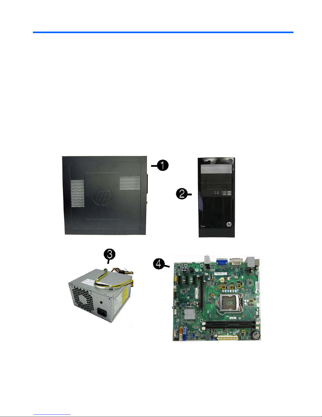
Microtower (MT) Chassis Spare Parts
Computer Major Components
Microtower (MT) Chassis Spare Parts 17

Item Description Spare part number
(1) Access panel 657104-001
(2) Front bezel
For use on 3300/3305 models 657109-001
For use on 7500/7300 models (not illustrated; bezel is identical except for branding) 657112-001
(3) Power supply, 300W 656721-001
(4) System board (includes replacement thermal material)
For use in models with AMD processors on 3305 models 638404-001
For use in models with 65W Intel processors on 3300 models 656598-001
For use in models with 95W Intel processors on 3300 models 660281-001
For use in models with Intel processors on 7300 models 656599-001
For use in models with Intel processors on 7500 models 687940-001
Memory modules (not illustrated)
PC3-10600, 1333-MHz for use in 7300 and 3300 series models
● 4-GB 585157-001
●
2-GB 635803-001
●
1-GB 635802-001
PC3-12800, 1666-MHz for use in 7500 models
●
4-GB 671613-001
●
2-GB 671612-001
Processors (include replacement thermal material; not illustrated)
Intel processors
Intel Core i7
● 3770K (3.5-GHz, 8-MB L3 cache, 77W) for use only on 7500 models 688165-001
●
3770 (3.4-GHz, 8-MB L3 cache, 77W) for use only on 7500 models 688164-001
●
2600S (2.8-GHz, 8-MB L3 cache, 65W) 638419-001
Intel Core i5
●
3570K (3.4-GHz, 6-MB L3 cache, 77W) for use only on 7500 models 688163-001
●
3570 (3.4-GHz, 6-MB L3 cache, 77W) for use only on 7500 models 688162-001
● 3550 (3.3-GHz, 6-MB L3 cache, 77W) for use only on 7500 models 687944-001
●
3470 (3.2-GHz, 6-MB L3 cache, 77W) for use only on 7500 models 687943-001
●
3450 (3.1-GHz, 6-MB L3 cache, 77W) for use only on 7500 models 687942-001
● 3330 (3.0-GHz, 6-MB L3 cache, 77W) for use only on 7500 models 687941-001
●
2500S (2.7-GHz, 6-MB L3 cache, 65W) 638420-001
●
2500 (3.3-GHz, 6-MB L3 cache, 65W) for use in 7500/7300 models 638631-001
18 Chapter 4 Illustrated parts catalog

Item Description Spare part number
●
2405S (2.5-GHz, 6-MB L3 cache, 65W) 656790-001
●
2400S (2.5-GHz, 6-MB L3 cache, 65W) 640953-001
● 2400 (3.1-GHz, 6-MB L3 cache, 65W) for use in 7500/7300 models 638630-001
●
2320 (3.0 GHz, 6-MB L3 cache, 95W) for use in 3300 series models 665121-001
●
2310 (2.9-GHz, 6-MB L3 cache, 65W) for use in 7500/7300 models 657111-001
● 2300 (2.8-GHz, 6-MB L3 cache, 65W) for use in 7500/7300 models 654601-001
Intel Core i3
●
2130 (3.4 GHz, 3-MB L3 cache, 65W) for use in 3300 series models 665120-001
● 2120 (3.3-GHz, 3-MB L3 cache, 65W) 638629-001
●
2105 (3.1-GHz, 3-MB L3 cache, 65W) 655970-001
●
2100 (3.1-GHz, 3-MB L3 cache, 65W) 638628-001
Intel Pentium Dual-Core
●
G860 (3.0 GHz, 3-MB L3 cache, 65W) 665122-001
●
G850 (2.9-GHz, 3-MB L3 cache, 65W) 655973-001
● G840 (2.8-GHz, 3-MB L3 cache, 65W) 655972-001
●
G630 (2.7 GHz, 3-MB L3 cache, 65W) 665123-001
●
G620 (2.6-GHz, 3-MB L3 cache, 65W) 655971-001
AMD processors (for use in model 3305)
Phenom II
●
X6 1065T, quad core, 2-MB L2 cache, 2.9 GHz, E0 666426-001
● X6 1055T, quad core, 2-MB L2 cache, 2.8 GHz, C3 617838-001
●
X6 1035T, quad core, 2-MB L2 cache, 2.6 GHz, C3 617837-001
●
X4 z960T, dual core, 1-MB cache, 3.0 GHz, E0 632923-001
● X4 z840T, dual core, 1-MB cache, 2.9 GHz, E0 638410-001
●
X2 565, dual core, 1-MB cache, 3.4 GHz, C3 657101-001
●
X2 560, dual core, 1-MB cache, 3.3 GHz, C3 657100-001
● X2 550, dual core, 1-MB cache, 3.1 GHz, C3 614518-001
Athlon II X4
●
650, dual core, 2-MB cache, 3.2 GHz, C3 638004-001
● X4 645, dual core, 2-MB cache, 3.1 GHz, C3 628883-001
●
X4 635, dual core, 2-MB cache, 2.9 GHz, C3 617834-001
●
X3 455, dual core, 1.5-MB cache, 3.3 GHz, C3 638003-001
● X3 450, dual core, 1.5-MB cache, 3.2 GHz, C3 628882-001
●
X2 270, dual core, 1-MB cache, 3.4 GHz, C3 632922-001
Microtower (MT) Chassis Spare Parts 19

Item Description Spare part number
●
X2 265, dual core, 1-MB cache, 3.3 GHz, C3 632921-001
628881-001
●
X2 260, dual core, 1-MB cache, 3.2 GHz, C3 614513-001
●
X2 220, dual core, 1-MB cache, 2.8 GHz, C2 611192-001
Sempron
●
145, single core, 1-MB cache, 2.9 GHz, C3 638005-001
20 Chapter 4 Illustrated parts catalog
 Loading...