

Page 1

Maintenance & Service Guide
HP Pro 2110 Small Form Factor
HP Pro 3120 Minitower
HP Pro 3120 Small Form Factor
HP Pro 3125 Minitower
HP Pro 3130 Minitower
HP Pro 3130 Small Form Factor
Page 2

© Copyright 2010 Hewlett-Packard
Development Company, L.P. The information
contained herein is subject to change
without notice.
Microsoft and Windows are trademarks of
Microsoft Corporation in the U.S. and other
countries.
The only warranties for HP products and
services are set forth in the express warranty
statements accompanying such products and
services. Nothing herein should be
construed as constituting an additional
warranty. HP shall not be liable for technical
or editorial errors or omissions contained
herein.
This document contains proprietary
information that is protected by copyright.
No part of this document may be
photocopied, reproduced, or translated to
another language without the prior written
consent of Hewlett-Packard Company.
Maintenance & Service Guide
HP Pro 2110 Small Form Factor
HP Pro 3120 Minitower
HP Pro 3120 Small Form Factor
HP Pro 3125 Minitower
HP Pro 3130 Minitower
HP Pro 3130 Small Form Factor
First Edition (May 2010)
Document Part Number: 621937-001
Page 3

About This Book
WARNING! Text set off in this manner indicates that failure to follow directions could result in bodily
harm or loss of life.
CAUTION: Text set off in this manner indicates that failure to follow directions could result in damage
to equipment or loss of information.
NOTE: Text set off in this manner provides important supplemental information.
iii
Page 4

iv About This Book
Page 5

Table of contents
1 Installing and Customizing the Software ........................................................................... 1
Installing the Operating System .................................................................................................. 1
Downloading Microsoft Windows Updates ................................................................................. 2
Installing or Upgrading Device Drivers (Windows systems) ............................................................ 2
Accessing Disk Image (ISO) Files ............................................................................................... 2
Protecting the Software ............................................................................................................. 3
2 Computer Setup (F10) Utility ............................................................................................. 4
HP Pro 2110 – Computer Setup (F10) Utilities ............................................................................. 4
Using Computer Setup (F10) Utilities ............................................................................ 5
Computer Setup—Main ............................................................................................. 6
Computer Setup—Advanced ...................................................................................... 7
Computer Setup—Boot .............................................................................................. 8
Computer Setup—Power ............................................................................................ 9
Computer Setup—PC Health ..................................................................................... 10
Computer Setup—Exit .............................................................................................. 10
HP Pro 3120 – Computer Setup (F10) Utilities ........................................................................... 11
Using Computer Setup (F10) Utilities .......................................................................... 11
Computer Setup—Main ........................................................................................... 12
Computer Setup—Advanced .................................................................................... 14
Computer Setup—Power .......................................................................................... 15
Computer Setup—Boot ............................................................................................ 16
Computer Setup—Exit .............................................................................................. 17
HP Pro 3125 – Computer Setup (F10) Utilities ........................................................................... 17
Using Computer Setup (F10) Utilities .......................................................................... 17
Computer Setup—Main ........................................................................................... 18
Computer Setup—Advanced .................................................................................... 20
Computer Setup—Power .......................................................................................... 21
Computer Setup—Boot ............................................................................................ 21
Computer Setup—Exit .............................................................................................. 22
HP Pro 3130 – Computer Setup (F10) Utilities ........................................................................... 23
Using Computer Setup (F10) Utilities .......................................................................... 23
Computer Setup—Main ........................................................................................... 24
Computer Setup—Advanced .................................................................................... 26
v
Page 6

Computer Setup—Power .......................................................................................... 27
Computer Setup—Boot ............................................................................................ 28
Computer Setup—Exit .............................................................................................. 29
3 Serial ATA (SATA) Drive Guidelines and Features ............................................................. 30
SATA Hard Drives .................................................................................................................. 30
SATA Hard Drive Cables ........................................................................................................ 30
SATA Data Cable ................................................................................................... 30
SMART ATA Drives ................................................................................................................ 31
Hard Drive Capacities ............................................................................................................ 31
4 Identifying the Chassis, Routine Care, and Disassembly Preparation ............................... 32
Chassis Designation ............................................................................................................... 33
Minitower .............................................................................................................. 33
Small Form Factor ................................................................................................... 34
Electrostatic Discharge Information ........................................................................................... 35
Generating Static .................................................................................................... 35
Preventing Electrostatic Damage to Equipment ............................................................ 35
Personal Grounding Methods and Equipment ............................................................. 36
Grounding the Work Area ....................................................................................... 36
Recommended Materials and Equipment .................................................................... 37
Operating Guidelines ............................................................................................................. 37
Routine Care ......................................................................................................................... 38
General Cleaning Safety Precautions ......................................................................... 38
Cleaning the Computer Case .................................................................................... 38
Cleaning the Keyboard ............................................................................................ 38
Cleaning the Monitor ............................................................................................... 39
Cleaning the Mouse ................................................................................................ 39
Service Considerations ........................................................................................................... 39
Power Supply Fan ................................................................................................... 39
Tools and Software Requirements .............................................................................. 40
Screws ................................................................................................................... 40
Cables and Connectors ........................................................................................... 40
Hard Drives ............................................................................................................ 40
Lithium Coin Cell Battery .......................................................................................... 41
5 Removal and Replacement Procedures Minitower (MT) Chassis ....................................... 42
Preparation for Disassembly .................................................................................................... 42
Access Panel ......................................................................................................................... 43
Front Bezel ............................................................................................................................ 44
Bezel Blanks .......................................................................................................................... 45
Memory ................................................................................................................................ 45
DDR3-SDRAM DIMMs .............................................................................................. 45
vi
Page 7

Populating DIMM Sockets ........................................................................................ 47
Installing Memory Modules ....................................................................................... 52
Expansion Cards .................................................................................................................... 54
Cable Management ............................................................................................................... 60
Cable Connections .................................................................................................. 61
HP Pro 3120 ........................................................................................... 61
HP Pro 3125 ........................................................................................... 61
HP Pro 3130 ........................................................................................... 62
Drives ................................................................................................................................... 63
Drive Positions ........................................................................................................ 63
Installing Additional Drives ....................................................................................... 64
System Board Drive Connections ................................................................ 65
Removing an Optical Drive ........................................................................ 68
Removing an Internal 3.5-inch Hard Drive ................................................... 69
Front I/O and USB Panel Housing Assembly ............................................................................. 72
Power Switch/LED Assembly ................................................................................................... 73
System Fan ............................................................................................................................ 74
Heat sink assembly ................................................................................................................. 75
Processor .............................................................................................................................. 76
Power Supply ........................................................................................................................ 79
System Board ........................................................................................................................ 82
Battery .................................................................................................................................. 84
Type 1 Battery Holder .............................................................................................. 85
Type 2 Battery Holder .............................................................................................. 85
Type 3 Battery Holder .............................................................................................. 86
6 Removal and Replacement Procedures Small Form Factor (SFF) Chassis ........................... 87
Preparation for Disassembly .................................................................................................... 87
Access Panel ......................................................................................................................... 88
Front Bezel ............................................................................................................................ 89
Installing Additional Memory ................................................................................................... 90
DIMMs .................................................................................................................. 90
DDR3-SDRAM DIMMs .............................................................................................. 90
Populating DIMM Sockets ........................................................................................ 91
Installing DIMMs ..................................................................................................... 95
Expansion Cards .................................................................................................................... 97
System Fan .......................................................................................................................... 103
Cable Management ............................................................................................................. 104
Cable Connections ................................................................................................ 105
HP Pro 2110 ......................................................................................... 105
HP Pro 3120 ......................................................................................... 105
HP Pro 3130 ......................................................................................... 106
Optical Drive Eject Button ..................................................................................................... 107
vii
Page 8

Drives ................................................................................................................................. 109
Drive Positions ...................................................................................................... 109
Installing and Removing Drives ............................................................................... 110
System Board Drive Connections .............................................................. 111
Removing the Optical Drive ..................................................................... 113
Removing the Hard Drive ........................................................................ 114
Front I/O Assembly .............................................................................................................. 117
Power Switch/LED Assembly ................................................................................................. 119
Heat sink ............................................................................................................................ 122
Processor ............................................................................................................................ 123
Power Supply ...................................................................................................................... 126
System Board ...................................................................................................................... 128
Battery ................................................................................................................................ 130
Type 1 Battery Holder ............................................................................................ 131
Type 2 Battery Holder ............................................................................................ 131
7 Restore and Recovery ................................................................................................... 133
Microsoft System Restore ....................................................................................................... 133
System Recovery .................................................................................................................. 133
System Recovery Options ....................................................................................... 134
System Recovery from the Windows Start Menu ........................................................ 134
System Recovery at System Startup .......................................................................... 135
System Recovery from Recovery Discs ...................................................................... 135
Recovery Discs ..................................................................................................................... 136
Choosing Recovery Discs ....................................................................................... 136
Creating Recovery Discs ........................................................................................ 137
8 Computer Diagnostic Features ....................................................................................... 138
Hewlett-Packard Vision Diagnostics ........................................................................................ 138
Accessing HP Vision Diagnostics ............................................................................. 138
Survey Tab ........................................................................................................... 139
Test Tab ............................................................................................................... 140
Status Tab ............................................................................................................ 140
History Tab .......................................................................................................... 141
Errors Tab ............................................................................................................ 141
Help Tab .............................................................................................................. 142
Saving and Printing Information in HP Vision Diagnostics ........................................... 142
Downloading the Latest Version of HP Vision Diagnostics ........................................... 142
Protecting the Software ......................................................................................................... 143
9 Troubleshooting Without Diagnostics ............................................................................ 144
Safety and Comfort .............................................................................................................. 144
Before You Call for Technical Support .................................................................................... 144
viii
Page 9

Helpful Hints ........................................................................................................................ 145
Solving General Problems ..................................................................................................... 147
Solving Diskette Problems ...................................................................................................... 151
Solving Hard Drive Problems ................................................................................................. 153
Solving Media Card Reader Problems .................................................................................... 154
Solving Display Problems ...................................................................................................... 156
Solving Audio Problems ........................................................................................................ 159
Solving Printer Problems ........................................................................................................ 161
Solving Keyboard and Mouse Problems .................................................................................. 162
Solving Hardware Installation Problems .................................................................................. 165
Solving Network Problems .................................................................................................... 167
Solving Memory Problems ..................................................................................................... 170
Solving CD-ROM and DVD Problems ...................................................................................... 171
Solving USB Flash Drive Problems .......................................................................................... 174
Solving Front Panel Component Problems ................................................................................ 175
Solving Internet Access Problems ............................................................................................ 176
Solving Software Problems .................................................................................................... 179
Contacting Customer Support ................................................................................................ 180
10 POST Error Messages .................................................................................................. 181
POST Text Messages ............................................................................................................ 181
Interpreting POST Diagnostic Audible Codes ........................................................................... 182
11 Password Security and Resetting CMOS ...................................................................... 184
Resetting the Password Jumper ............................................................................................... 184
Clearing and Resetting the CMOS ......................................................................................... 185
Appendix A Connector Pin Assignments ........................................................................... 187
Ethernet BNC ...................................................................................................................... 187
USB .................................................................................................................................... 187
Microphone ........................................................................................................................ 187
Headphone ......................................................................................................................... 188
Line-in Audio ....................................................................................................................... 188
Line-out Audio ...................................................................................................................... 188
4-Pin Power (for CPU) ........................................................................................................... 188
Monitor .............................................................................................................................. 189
24-Pin Power ....................................................................................................................... 189
PCI Express ......................................................................................................................... 190
PCI Express ......................................................................................................................... 191
Appendix B Power Cord Set Requirements ....................................................................... 192
General Requirements .......................................................................................................... 192
Japanese Power Cord Requirements ....................................................................................... 192
ix
Page 10

Country-Specific Requirements ............................................................................................... 193
Appendix C Specifications ................................................................................................ 194
Minitower models ................................................................................................................ 194
Small form factor models ....................................................................................................... 195
Index ............................................................................................................................... 196
x
Page 11

1 Installing and Customizing the
Software
If your computer was not shipped with a Microsoft operating system, some portions of this
documentation do not apply. Additional information is available in online help after you install the
operating system.
NOTE: If the computer was shipped with Windows Vista or Windows 7 loaded, you will be
prompted to register the computer with HP Total Care before installing the operating system. You will
see a brief movie followed by an online registration form. Fill out the form, click the Begin button, and
follow the instructions on the screen.
CAUTION: Do not add optional hardware or third-party devices to the computer until the operating
system is successfully installed. Doing so may cause errors and prevent the operating system from
installing properly.
NOTE: Be sure there is a 10.2-cm (4-inch) clearance at the back of the unit and above the monitor to
permit the required airflow.
Installing the Operating System
The first time you turn on the computer, the operating system is installed automatically. This process
takes about 5 to 10 minutes, depending on which operating system is being installed. Carefully read
and follow the instructions on the screen to complete the installation.
CAUTION: Once the automatic installation has begun, DO NOT TURN OFF THE COMPUTER UNTIL
THE PROCESS IS COMPLETE. Turning off the computer during the installation process may damage the
software that runs the computer or prevent its proper installation.
NOTE: If the computer shipped with more than one operating system language on the hard drive, the
installation process could take up to 60 minutes.
If your computer was not shipped with a Microsoft operating system, some portions of this
documentation do not apply. Additional information is available in online help after you install the
operating system.
Installing the Operating System
1
Page 12

Downloading Microsoft Windows Updates
1. To set up your Internet connection, click Start > Internet Explorer and follow the instructions
on the screen.
2. Once an Internet connection has been established, click the Start button.
3. Select the All Programs menu.
4. Click on the Windows Update link.
In Windows Vista and Windows 7, the Windows Update screen appears. Click view
available updates and make sure all critical updates are selected. Click the Install button and
follow the instructions on the screen.
In Windows XP, you will be directed to the Microsoft Windows Update Web site. If you see
one or more pop-up windows that ask you to install a program from
click Yes to install the program. Follow the instructions on the Microsoft Web site to scan for
updates and install critical updates and service packs.
It is recommended that you install all of the critical updates and service packs.
After the updates have been installed, Windows will prompt you to reboot the machine. Be sure to
5.
save any files or documents that you may have open before rebooting. Then select Yes to reboot
the machine.
http://www.microsoft.com,
Installing or Upgrading Device Drivers (Windows systems)
When installing optional hardware devices after the operating system installation is complete, you must
also install the drivers for each of the devices.
If prompted for the i386 directory, replace the path specification with C:\i386, or use the Browse
button in the dialog box to locate the i386 folder. This action points the operating system to the
appropriate drivers.
Obtain the latest support software, including support software for the operating system from
http://www.hp.com/support. Select your country and language, select Download drivers and
software (and firmware), enter the model number of the computer, and press Enter.
Accessing Disk Image (ISO) Files
There are disk image files (ISO files) included on your PC that contain the installation software for
additional software. These CD image files are located in the folder C:\SWSetup\ISOs. Each .iso file
can be burned to CD media to create an installation CD. It is recommended that these disks be created
and the software installed in order to get the most from your PC. The software and image file names
are:
Corel WinDVD SD and BD – installation software for WinDVD – used to play DVD movies
●
HP Insight Diagnostics OR Vision Diagnostics – software to perform diagnostic activities on your
●
PC
2 Chapter 1 Installing and Customizing the Software
Page 13

Protecting the Software
To protect the software from loss or damage, keep a backup copy of all system software, applications,
and related files stored on the hard drive. Refer to the operating system or backup utility documentation
for instructions on making backup copies of your data files.
Protecting the Software
3
Page 14

2 Computer Setup (F10) Utility
The computer setup utility differs for the different models.
HP Pro 2110 – Computer Setup (F10) Utilities
Use Computer Setup (F10) Utility to do the following:
Change factory default settings.
●
Set the system date and time.
●
Set, view, change, or verify the system configuration, including settings for processor, graphics,
●
memory, audio, storage, communications, and input devices.
Modify the boot order of bootable devices such as hard drives, diskette drives, optical drives, or
●
USB flash media devices.
Restrict a device from booting the unit.
●
Run hard drive self-tests.
●
View CPU and system temperatures.
●
Establish a supervisor password that controls access to Computer Setup (F10) Utility and the
●
settings described in this section.
Secure integrated I/O functionality, including the serial, USB, or parallel ports, audio, or
●
embedded NIC, so that they cannot be used until they are unsecured.
Enable or disable pre-boot messages.
●
Enable or disable USB legacy support.
●
4 Chapter 2 Computer Setup (F10) Utility
Page 15

Using Computer Setup (F10) Utilities
Computer Setup can be accessed only by turning the computer on or restarting the system. To access
the Computer Setup Utilities menu, complete the following steps:
Turn on or restart the computer.
1.
As soon as the computer is turned on, press F10 before the system boots to the operating system
2.
to enter Computer Setup. Press Enter to bypass the title screen, if necessary.
NOTE: If you do not press F10 at the appropriate time, you must restart the computer and again
press F10 before the unit boots to the operating system to access the utility.
The Computer Setup Utility screen is divided into menu headings and actions.
3.
Six menu headings appear on the Computer Setup Utility screen:
Main
●
Advanced
●
Boot
●
Power
●
PC Health
●
Exit
●
Use the arrow keys to select the appropriate heading, then press Enter. Use the arrow (up and
down) keys to select the option you want, then press Enter. To return to the previous screen, press
Esc.
To apply and save changes, press the F10 key.
4.
If you have made changes that you do not want applied, press the F5 key to return to the previous
values.
To load optimized default values, press the F7 key.
CAUTION: Do NOT turn the computer power OFF while the ROM is saving the Computer Setup
(F10) changes because the CMOS could become corrupted. It is safe to turn off the computer only after
exiting the F10 Setup screen.
Table 2-1 Computer Setup (F10) Utility Main Menu
Heading Table
Main
Advanced
Boot
Computer Setup—Main on page 6
Computer Setup—Advanced on page 7
Computer Setup—Boot on page 8
Power
PC Health
Exit
Computer Setup—Power on page 9
Computer Setup—PC Health on page 10
Computer Setup—Exit on page 10
HP Pro 2110 – Computer Setup (F10) Utilities
5
Page 16

Computer Setup—Main
NOTE: Support for specific Computer Setup options may vary depending on the hardware
configuration.
Table 2-2 Computer Setup—Main
Option Description
System Information
System IDs
Allows you to view the following system information:
Processor Type (view only)
●
Processor Speed (view only)
●
CPUID/PatchID (view only)
●
Cache Size (view only)
●
Memory Size (view only)
●
Integrated MAC (view only)
●
System BIOS (view only)
●
Allows you to view or change the following system identification information:
Product Name (press Enter to change)
●
Serial Number (press Enter to change)
●
UUID (press Enter to change)
●
SKU Number (press Enter to change)
●
Family Name (view only)
●
Asset Tag Number (press Enter to change)
●
Feature Byte (press Enter to change)
●
Build ID (press Enter to change)
●
Set Time and Date
SATA Port 1
SATA Port 2
SATA Port 3
SATA Port 4
Allows you to set system time and date.
Allows or displays the following for each SATA Port:
Port Configuration — Disable/enable SATA Port
●
HDD Self-Test for selected channel:
●
SMART Status Check
◦
HDD Short Self-Test
◦
HDD Extended Self-Test
◦
Vendor (view only)
●
Size (view only)
●
Firmware (view only)
●
6 Chapter 2 Computer Setup (F10) Utility
Page 17

Table 2-2 Computer Setup—Main (continued)
Option Description
SATA Controller
Onboard FDC
Controller
Drive A
Halt On
POST Delay
Allows you to choose how the SATA controller and devices are accessed by the operating system.
The following options are available:
Native Mode - 4 SATA port
●
Compatible Mode - 2 PATA devices and 2 SATA devices (ports)
●
Disables/enables the floppy disk controller.
(view only)
Allows you to set POST error behavior to:
No Errors
●
All Errors
●
All But Keyboard
●
Allows you to set a POST delay to:
0 seconds
●
5 seconds
●
10 seconds
●
15 seconds
●
30 seconds
●
Computer Setup—Advanced
NOTE: Support for specific Computer Setup options may vary depending on the hardware
configuration.
Table 2-3 Computer Setup—Advanced
Option Description
Execute Disable Bit
Intel (R)
Virtualization Tech
Init Display First
Disables/enables hardware DEP function.
Allows you to enable/disable the processor's Virtualization Technology feature.
Allows you to select the primary display device:
OnChip VGA
●
PCI Slot
●
PCIEx
●
HP Pro 2110 – Computer Setup (F10) Utilities
7
Page 18

Table 2-3 Computer Setup—Advanced (continued)
Option Description
MAX DVMT
Allocation
Onboard HD Audio
OnChip USB
Controller
USB Legacy Support
Onboard LAN
Onboard LAN Boot
ROM
Onboard Serial Port
1
Allows you to specify the DVMT/system memory allocated for video memory:
128MB
●
256MB
●
Max
●
Allows you to disable/enable onboard HD audio.
Disables/enables the universal host controller interface for USB (Universal Serial Bus).
Disables/enables USB legacy support function (USB keyboard, USB mouse, and USB flash media).
Disables/enables onboard LAN controller.
Disables/enables the boot ROM of the onboard LAN chip.
Allows you to select a setting for the onboard serial port:
Disabled
●
3F8/IRQ4
●
2F8/IRQ3
●
3E8/IRQ4
●
●
Computer Setup—Boot
NOTE: Support for specific Computer Setup options may vary depending on the hardware
configuration.
Table 2-4 Computer Setup—Boot
Option Description
ESC Boot Menu
F9 Diagnostics
F10 Setup Prompt
F11 Recovery
Allows you to enable/disable the option to press the ESC key to access the Boot menu during
computer startup.
Disables/enables F9 Boot Menu prompt message on the logo screen.
Disables/enables the F10 Setup prompt message on the logo screen.
Disables/enables F11 Recovery and provides the option of showing the F11 Recovery prompt
message on the logo screen. Choose from the following:
●
●
●
2E8/IRQ3
Disabled
Enabled no prompt
Enabled and prompt
8 Chapter 2 Computer Setup (F10) Utility
Page 19

Table 2-4 Computer Setup—Boot (continued)
Option Description
F12 Boot from LAN
Prompt
Hard Disk Boot Seq.
Optical Drive Boot
Seq.
Network Boot Seq.
First Boot Device
Second Boot Device
Third Boot Device
Fourth Boot Device
Set Supervisor
Password
Disables/enables the F12 Boot from LAN prompt message on the logo screen.
Allows you to specify the order of attached hard drive devices (such as USB HDD storage or USB
flash media). The first drive in the order has priority in the boot sequence and is recognized as
drive C (if any devices are attached).
Allows you to specify the order in which attached optical drives (including USB ODD) are checked
for a bootable operating system image.
Allows you to specify the order in which network devices (including UP NIC cards) are checked for
a bootable operating system image.
Allows you to specify which devices will boot first, second, third, and fourth or to disable any of the
four:
Removable
●
CDROM
●
Hard Disk
●
Network
●
NOTE: MS-DOS drive lettering assignments may not apply after a non-MS-DOS operating system
has started.
Allows you to establish a password to control access to Computer Setup.
BIOS Write
Protection
Disables/enables BIOS upgrading.
Computer Setup—Power
NOTE: Support for specific Computer Setup options may vary depending on the hardware
configuration.
Table 2-5 Computer Setup—Power
Option Description
After AC Power Loss
Wake on PCI Device
from S5
RTC Alarm Resume
Allows you to select system power loss behavior:
Off
●
On
●
Last State
●
Disables/enables waking up from S5 by PCI device.
Disables/enables RTC (real-time clock) alarm.
HP Pro 2110 – Computer Setup (F10) Utilities
9
Page 20

Computer Setup—PC Health
NOTE: Support for specific Computer Setup options may vary depending on the hardware
configuration.
Table 2-6 Computer Setup—PC Health
Option Description
Chassis Opened
Warning
System Fan Fail
Check
Smart Fan Function
Current CPU
Temperature
Current System
Temperature
Current CPU Fan
Speed
Current System Fan
Speed
Allows you to disable/enable the chassis intrusion function and clear the intrusion warning.
Disables/enables detection of system fan during POST.
Disables/enables Smart Fan functionality. Enabling optimizes fan control for best acoustic behavior.
(view only)
(view only)
(view only)
(view only)
Computer Setup—Exit
Table 2-7 Computer Setup—Exit
Option Description
Save & Exit Setup
Allows you to save current settings and exit Computer Setup.
Exit Without Saving
Load Optimal
Defaults
Allows you to exit Computer Setup without saving changes.
Allows you to reset Computer Setup to factory defaults.
10 Chapter 2 Computer Setup (F10) Utility
Page 21

HP Pro 3120 – Computer Setup (F10) Utilities
Use Computer Setup (F10) Utility to do the following:
Change factory default settings.
●
Set the system date and time.
●
Set, view, change, or verify the system configuration, including settings for graphics, audio,
●
storage, communications, and input devices.
View settings for processor and memory.
●
Modify the boot order of bootable devices such as hard drives, optical drives, or USB flash media
●
devices.
Run hard drive self-tests.
●
Establish a supervisor password that controls access to Computer Setup (F10) Utility and the
●
settings described in this section.
Using Computer Setup (F10) Utilities
Computer Setup can be accessed only by turning the computer on or restarting the system. To access
the Computer Setup Utilities menu, complete the following steps:
Turn on or restart the computer.
1.
As soon as the computer is turned on, press F10 before the computer boots to the operating
2.
system to enter Computer Setup.
NOTE: If you do not press F10 at the appropriate time, you must restart the computer and again
press F10 before the computer boots to the operating system to access the utility.
The Computer Setup Utility screen is divided into menu headings and actions.
3.
Five menu headings appear on the Computer Setup Utility screen:
Main
●
Advanced
●
Power
●
Boot
●
Exit
●
Use the arrow keys to select the appropriate heading, then press Enter. Use the arrow (up and
down) keys to select the option you want, then press Enter. To return to the previous screen, press
Esc.
CAUTION: Do NOT turn the computer power OFF while the ROM is saving the Computer Setup
(F10) changes because the CMOS could become corrupted. It is safe to turn off the computer only after
exiting the F10 Setup screen.
HP Pro 3120 – Computer Setup (F10) Utilities
11
Page 22

Computer Setup—Main
NOTE: Support for specific Computer Setup options may vary depending on the hardware
configuration.
Table 2-8 Computer Setup—Main
Option Description
System Time
System Date
System IDs
Language
Floppy Diskette A
Allows you to set system time.
Allows you to set system date.
Allows you to view the following system identification information:
Product Name (view only)
●
Serial Number (view only)
●
UUID (view only)
●
SKU Number (view only)
●
Family Name (view only)
●
Feature Byte (view only)
●
Build ID (view only)
●
Allows you to select language.
Allows you to set drive A to:
Disabled
●
1.44 MB 3.5”
●
Not Installed (default)
●
12 Chapter 2 Computer Setup (F10) Utility
Page 23

Table 2-8 Computer Setup—Main (continued)
1st Drive
2nd Drive
3rd Drive
4th Drive
System Information
For each, allows you to adjust or view:
Capacity (Size - HDD only) - view only
●
Transfer Mode- view only
●
Smart Support - run HDD self-test for selected channel:
●
SMART Status Check
◦
SMART Short Self-Test
◦
SMART Extended Self-Test
◦
Allows you to view:
Installed Memory
●
Memory Bank 1
●
Memory Bank 2
●
Memory Bank 3
●
Memory Bank 4
●
BIOS Revision
●
Core Version
●
HP Pro 3120 – Computer Setup (F10) Utilities
13
Page 24

Computer Setup—Advanced
NOTE: Support for specific Computer Setup options may vary depending on the hardware
configuration.
WARNING! Setting items on this menu to incorrect values may cause your system to malfunction.
Table 2-9 Computer Setup—Advanced
Option Description
CPU Type
CPU Speed
Cache RAM
Cache RAM (L2)
Cache RAM (L3)
Primary Video
Adapter
USB Ports
SATA Controller
SATA Controller
Mode
Onboard Audio
(view only)
(view only)
(view only)
(view only)
(view only)
Allows you to select the boot display device when more than 2 video options are offered by the
system:
PCI-E (default)
●
Onboard
●
Allows you to disable/enable individual USB ports.
Allows you to disable/enable the SATA controller. Default is enabled.
If SATA Controller is enabled, allows you to set the mode to:
IDE (default)
●
AHCI
●
RAID
●
Allows you to set the onboard audio to:
Enabled
●
Disabled
●
Auto (default)
●
Onboard LAN
Onboard LAN Boot
ROM
Change Supervisor
Password
Change User
Password
Supervisor
Password
User Password
Allows you to disable/enable onboard LAN controller. Default is enabled.
Disables/enables the boot ROM of the onboard LAN chip. Default is enabled.
Allows you to establish, disable, or change the supervisor password.
Allows you to establish, disable, or change the user password.
NOTE: Only displays if a Supervisor password is set.
Allows you to view whether the supervisor password is enabled or disabled.
Allows you to view whether the user password is enabled or disabled.
14 Chapter 2 Computer Setup (F10) Utility
Page 25

Computer Setup—Power
NOTE: Support for specific Computer Setup options may vary depending on the hardware
configuration.
Table 2-10 Computer Setup—Power
Option Description
After AC Power
Failure
XD (Execute Disable)
(if supported by
hardware)
Virtualization
Technology
WOL in S5
Allows you to select system restart behavior after power loss:
Auto
●
Power On
●
Stay Off (default)
●
Allows you to disable/enable the processor's XD feature. Default is enabled.
Allows you to enable/disable the processor's Virtualization Technology feature. Default is disabled.
Disables/enables limited Wake on LAN from S5. Note that the computer can only wake from S5
during a normal shutdown event. Default is disabled.
HP Pro 3120 – Computer Setup (F10) Utilities
15
Page 26

Computer Setup—Boot
NOTE: Support for specific Computer Setup options may vary depending on the hardware
configuration.
Table 2-11 Computer Setup—Boot
Option Description
Boot-time
Diagnostic
Screen
Boot Device
Priority
Disables/enables POST diagnostic messages display during boot. Default is disabled.
Allows you to specify which device groups will boot first, second, third, and fourth or to disable any of
the four. Also allows you to set the device boot priority within each group.
1st Boot Device
2nd Boot Device
3rd Boot Device
4th Boot Device
Floppy Group
Boot Priority
CD-ROM Group
Boot Priority
HDD Group Boot
Priority
Allows you to set the device group boot priority:
CD-ROM Group
●
Hard Drive Group
●
Floppy Group
●
Network Boot Group
●
NOTE: MS-DOS drive lettering assignments may not apply after a non-MS-DOS
operating system has started.
Specifies boot device priority within removable devices.
NOTE: This computer does not support floppy drives.
Specifies boot device priority within CD/DVD drives.
Specifies boot device priority within hard drives.
Network Group
Boot Priority
16 Chapter 2 Computer Setup (F10) Utility
Specifies boot device priority within bootable network devices.
Page 27

Computer Setup—Exit
NOTE: Support for specific Computer Setup options may vary depending on the hardware
configuration.
Table 2-12 Computer Setup—Exit
Option Description
Exit Saving Changes
Exit Discarding
Changes
Load Setup Defaults
Discard Changes
Save Changes
Press Enter to exit saving changes.
Press Enter to exit discarding changes.
Press Enter to load setup defaults.
Press Enter to discard changes.
Press Enter to save changes.
HP Pro 3125 – Computer Setup (F10) Utilities
Use Computer Setup (F10) Utility to do the following:
Change factory default settings.
●
Set the system date and time.
●
Set, view, change, or verify the system configuration, including settings for graphics, audio,
●
storage, communications, and input devices.
View settings for processor and memory.
●
Modify the boot order of bootable devices such as hard drives, optical drives, or USB flash media
●
devices.
Run hard drive self-tests.
●
Establish a supervisor password that controls access to Computer Setup (F10) Utility and the
●
settings described in this section.
Using Computer Setup (F10) Utilities
Computer Setup can be accessed only by turning the computer on or restarting the system. To access
the Computer Setup Utilities menu, complete the following steps:
Turn on or restart the computer.
1.
As soon as the computer is turned on, press F10 before the computer boots to the operating
2.
system to enter Computer Setup.
NOTE: If you do not press F10 at the appropriate time, you must restart the computer and again
press F10 before the computer boots to the operating system to access the utility.
The Computer Setup Utility screen is divided into menu headings and actions.
3.
HP Pro 3125 – Computer Setup (F10) Utilities
17
Page 28

Five menu headings appear on the Computer Setup Utility screen:
Main
●
Advanced
●
Power
●
Boot
●
Exit
●
Use the arrow keys to select the appropriate heading, then press Enter. Use the arrow (up and
down) keys to select the option you want, then press Enter. To return to the previous screen, press
Esc.
CAUTION: Do NOT turn the computer power OFF while the ROM is saving the Computer Setup
(F10) changes because the CMOS could become corrupted. It is safe to turn off the computer only after
exiting the F10 Setup screen.
Computer Setup—Main
NOTE: Support for specific Computer Setup options may vary depending on the hardware
configuration.
Table 2-13 Computer Setup—Main
Option Description
System Time
System Date
System IDs
Language
Floppy Diskette A
Allows you to set system time.
Allows you to set system date.
Allows you to view or change the following system identification information:
Product Name (press Enter to change)
●
Serial Number (press Enter to change)
●
UUID (press Enter to change)
●
● SKU Number (press Enter to change)
Family Name (view only)
●
Feature Byte (press Enter to change)
●
Build ID (press Enter to change)
●
Allows you to select language.
Allows you to set drive A to:
Disabled
●
1.44 MB 3.5”
●
Not Installed
●
18 Chapter 2 Computer Setup (F10) Utility
Page 29

Table 2-13 Computer Setup—Main (continued)
1st Drive
2nd Drive
3rd Drive
4th Drive
System Information
For each, allows you to adjust or view:
Port Configuration - disable/enable the SATA port for the selected drive
●
Capacity (Size - HDD only) - view only
●
Transfer Mode- view only
●
Smart Support - run HDD self-test for selected channel:
●
SMART Status Check
◦
SMART Short Self-Test
◦
SMART Extended Self-Test
◦
Allows you to view:
Installed Memory
●
● Memory Bank 1
Memory Bank 2
●
Memory Bank 3
●
Memory Bank 4
●
BIOS Revision
●
Core Version
●
HP Pro 3125 – Computer Setup (F10) Utilities
19
Page 30

Computer Setup—Advanced
NOTE: Support for specific Computer Setup options may vary depending on the hardware
configuration.
WARNING! Setting items on this menu to incorrect values may cause your system to malfunction.
Table 2-14 Computer Setup—Advanced
Option Description
CPU Type
CPU Speed
Cache RAM (L2)
Cache RAM (L3)
Primary Video
Adapter
SATA1 Controller
SATA1 Controller
Mode
USB Ports
Onboard LAN
Onboard LAN Boot
ROM
(view only)
(view only)
(view only)
(view only)
Allows you to select the boot display device when more than 2 video options are offered by the
system:
Onboard
●
PCI-E
●
Allows you to disable/enable the SATA controller.
If SATA Controller is enabled, allows you to set the mode to:
IDE
●
AHCI
●
Allows you to disable/enable individual USB ports.
Allows you to disable/enable onboard LAN controller.
Disables/enables the boot ROM of the onboard LAN chip.
Supervisor
Password
User Password
Change Supervisor
Password
Change User
Password
Onboard Audio
Allows you to view whether the supervisor password is enabled or disabled.
Allows you to view whether the user password is enabled or disabled.
NOTE: Only displays if a Supervisor password is set.
Allows you to establish, disable, or change the supervisor password.
Allows you to establish, disable, or change the user password.
NOTE: Only displays if a Supervisor password is set.
Allows you to set the onboard audio to:
Disabled
●
Enabled
●
Auto
●
20 Chapter 2 Computer Setup (F10) Utility
Page 31

Computer Setup—Power
NOTE: Support for specific Computer Setup options may vary depending on the hardware
configuration.
Table 2-15 Computer Setup—Power
Option Description
After AC Power
Failure
S5 Maximum Power
Savings
WOL in S5
NX (No Execute)
Virtualization
Technology
Allows you to select system restart behavior after power loss:
●
●
●
Disables/enables S5 Maximum Power Savings. Enabling this feature reduces the power of this
system as much as possible in the S5 state. This feature must be disabled if you want to enable
Wake on LAN from S5.
Disables/enables limited Wake on LAN from S5. Note that the computer can only wake from S5
during a normal shutdown event. The S5 Maximum Power Savings feature must be disabled in
order to enable limited Wake on LAN from S5.
Allows you to disable/enable the processor's NX feature.
Allows you to enable/disable the processor's Virtualization Technology feature.
Computer Setup—Boot
NOTE: Support for specific Computer Setup options may vary depending on the hardware
configuration.
Stay Off
Power On
Auto
Table 2-16 Computer Setup—Boot
Option Description
Boot-time
Diagnostic
Screen
Disables/enables POST diagnostic messages display during boot.
HP Pro 3125 – Computer Setup (F10) Utilities
21
Page 32

Table 2-16 Computer Setup—Boot (continued)
Boot Device
Priority
Allows you to specify which device groups will boot first, second, third, and fourth or to disable any of
the four. Also allows you to set the device boot priority within each group.
1st Boot Device
2nd Boot Device
3rd Boot Device
4th Boot Device
Floppy Group
Boot Priority
CD-ROM Group
Boot Priority
HDD Group Boot
Priority
Network Group
Boot Priority
Allows you to set the device group boot priority:
CD-ROM Group
●
Hard Drive Group
●
Floppy Group
●
Network Boot Group
●
NOTE: MS-DOS drive lettering assignments may not apply after a non-MS-DOS
operating system has started.
Specifies boot device priority within removable devices.
NOTE: This computer does not support floppy drives.
Specifies boot device priority within CD/DVD drives.
Specifies boot device priority within hard drives.
Specifies boot device priority within bootable network devices.
Computer Setup—Exit
NOTE: Support for specific Computer Setup options may vary depending on the hardware
configuration.
Table 2-17 Computer Setup—Exit
Option Description
Exit Saving Changes
Exit Discarding
Changes
Load Setup Defaults
Discard Changes
Save Changes
Press Enter to exit saving changes.
Press Enter to exit discarding changes.
Press Enter to load setup defaults.
Press Enter to discard changes.
Press Enter to save changes.
22 Chapter 2 Computer Setup (F10) Utility
Page 33

HP Pro 3130 – Computer Setup (F10) Utilities
Use Computer Setup (F10) Utility to do the following:
Change factory default settings.
●
Set the system date and time.
●
Set, view, change, or verify the system configuration, including settings for graphics, audio,
●
storage, communications, and input devices.
View settings for processor and memory.
●
Modify the boot order of bootable devices such as hard drives, optical drives, or USB flash media
●
devices.
Run hard drive self-tests.
●
Establish a supervisor password that controls access to Computer Setup (F10) Utility and the
●
settings described in this section.
Using Computer Setup (F10) Utilities
Computer Setup can be accessed only by turning the computer on or restarting the system. To access
the Computer Setup Utilities menu, complete the following steps:
Turn on or restart the computer.
1.
As soon as the computer is turned on, press F10 before the computer boots to the operating
2.
system to enter Computer Setup.
NOTE: If you do not press F10 at the appropriate time, you must restart the computer and again
press F10 before the computer boots to the operating system to access the utility.
The Computer Setup Utility screen is divided into menu headings and actions.
3.
Five menu headings appear on the Computer Setup Utility screen:
Main
●
Advanced
●
Power
●
Boot
●
Exit
●
Use the arrow keys to select the appropriate heading, then press Enter. Use the arrow (up and
down) keys to select the option you want, then press Enter. To return to the previous screen, press
Esc.
CAUTION: Do NOT turn the computer power OFF while the ROM is saving the Computer Setup
(F10) changes because the CMOS could become corrupted. It is safe to turn off the computer only after
exiting the F10 Setup screen.
HP Pro 3130 – Computer Setup (F10) Utilities
23
Page 34

Computer Setup—Main
NOTE: Support for specific Computer Setup options may vary depending on the hardware
configuration.
Table 2-18 Computer Setup—Main
Option Description
System Time
System Date
System IDs
Language
Floppy Diskette A
Allows you to set system time.
Allows you to set system date.
Allows you to view the following system identification information:
Product Name (view only)
●
Serial Number (view only)
●
UUID (view only)
●
SKU Number (view only)
●
Family Name (view only)
●
Feature Byte (view only)
●
Build ID (view only)
●
Allows you to select language.
Allows you to set drive A to:
Disabled
●
1.44 MB 3.5”
●
Not Installed (default)
●
24 Chapter 2 Computer Setup (F10) Utility
Page 35

Table 2-18 Computer Setup—Main (continued)
1st Drive
2nd Drive
3rd Drive
4th Drive
System Information
For each, allows you to adjust or view:
Capacity (Size - HDD only) - view only
●
Transfer Mode- view only
●
Smart Support - run HDD self-test for selected channel:
●
SMART Status Check
◦
SMART Short Self-Test
◦
SMART Extended Self-Test
◦
Allows you to view:
Installed Memory
●
Memory Bank 1
●
Memory Bank 2
●
Memory Bank 3
●
Memory Bank 4
●
BIOS Revision
●
Core Version
●
HP Pro 3130 – Computer Setup (F10) Utilities
25
Page 36

Computer Setup—Advanced
NOTE: Support for specific Computer Setup options may vary depending on the hardware
configuration.
WARNING! Setting items on this menu to incorrect values may cause your system to malfunction.
Table 2-19 Computer Setup—Advanced
Option Description
CPU Type
CPU Speed
Cache RAM
Cache RAM (L2)
Cache RAM (L3)
Primary Video
Adapter
USB Ports
SATA Controller
SATA Controller
Mode
Onboard Audio
(view only)
(view only)
(view only)
(view only)
(view only)
Allows you to select the boot display device when more than 2 video options are offered by the
system:
PCI-E
●
Onboard (default)
●
Allows you to disable/enable individual USB ports.
Allows you to disable/enable the SATA controller. Default is enabled.
If SATA Controller is enabled, allows you to set the mode to:
IDE
●
AHCI (default)
●
RAID
●
Allows you to set the onboard audio to:
Enabled
●
Disabled
●
Auto (default)
●
Onboard LAN
Onboard LAN Boot
ROM
Change Supervisor
Password
Change User
Password
Allows you to disable/enable onboard LAN controller. Default is enabled.
Disables/enables the boot ROM of the onboard LAN chip. Default is enabled.
Allows you to establish, disable, or change the supervisor password.
Allows you to establish, disable, or change the user password.
NOTE: Only displays if a Supervisor password is set.
26 Chapter 2 Computer Setup (F10) Utility
Page 37

Table 2-19 Computer Setup—Advanced (continued)
Onboard Video
Memory Size
Onboard 1394
DVMT/FIXED
Memory
Allows you to set onboard video memory size to:
Enabled, 32MB
●
Enabled, 64MB
●
Enabled, 128MB (default)
●
Allows you to enable/disable all 1394 ports. Default is enabled.
Allows you to specify the DVMT/system memory allocated for video memory:
128MB
●
256MB (default)
●
Maximum DVMT
●
Computer Setup—Power
NOTE: Support for specific Computer Setup options may vary depending on the hardware
configuration.
Table 2-20 Computer Setup—Power
Option Description
After AC Power
Failure
XD (Execute Disable)
(if supported by
hardware)
Virtualization
Technology
WOL in S5
Allows you to select system restart behavior after power loss:
Auto
●
Power On
●
Stay Off (default)
●
Allows you to disable/enable the processor's XD feature. Default is enabled.
Allows you to enable/disable the processor's Virtualization Technology feature. Default is disabled.
Disables/enables limited Wake on LAN from S5. Note that the computer can only wake from S5
during a normal shutdown event. Default is disabled.
HP Pro 3130 – Computer Setup (F10) Utilities
27
Page 38

Computer Setup—Boot
NOTE: Support for specific Computer Setup options may vary depending on the hardware
configuration.
Table 2-21 Computer Setup—Boot
Option Description
Boot-time
Diagnostic
Screen
Boot Device
Priority
Disables/enables POST diagnostic messages display during boot. Default is disabled.
Allows you to specify which device groups will boot first, second, third, and fourth or to disable any of
the four. Also allows you to set the device boot priority within each group.
1st Boot Device
2nd Boot Device
3rd Boot Device
4th Boot Device
Floppy Group
Boot Priority
CD-ROM Group
Boot Priority
HDD Group Boot
Priority
Allows you to set the device group boot priority:
CD-ROM Group
●
Hard Drive Group
●
Floppy Group
●
Network Boot Group
●
NOTE: MS-DOS drive lettering assignments may not apply after a non-MS-DOS
operating system has started.
Specifies boot device priority within removable devices.
NOTE: This computer does not support floppy drives.
Specifies boot device priority within CD/DVD drives.
Specifies boot device priority within hard drives.
Network Group
Boot Priority
ESC: Boot Menu
F9: Diagnostics
F10: Setup
F11: Recovery
F12: Boot from
LAN
Allows you to enable/disable the option to press the ESC key to access the Boot menu during computer
startup. Default is enabled.
Disables/enables the F9 Boot Menu prompt message on the logo screen. Default is enabled.
Disables/enables the F10 Setup prompt message on the logo screen. Default is enabled.
Disables/enables the F11 Recovery prompt message on the logo screen. Default is enabled.
Disables/enables the F12 Boot from LAN prompt message on the logo screen. Default is enabled.
28 Chapter 2 Computer Setup (F10) Utility
Specifies boot device priority within bootable network devices.
Page 39

Computer Setup—Exit
NOTE: Support for specific Computer Setup options may vary depending on the hardware
configuration.
Table 2-22 Computer Setup—Exit
Option Description
Exit Saving Changes
Exit Discarding
Changes
Load Setup Defaults
Discard Changes
Save Changes
Press Enter to exit saving changes.
Press Enter to exit discarding changes.
Press Enter to load setup defaults.
Press Enter to discard changes.
Press Enter to save changes.
HP Pro 3130 – Computer Setup (F10) Utilities
29
Page 40

3 Serial ATA (SATA) Drive Guidelines
and Features
NOTE: HP only supports the use of SATA hard drives on these models of computer. No Parallel ATA
(PATA) drives are supported.
SATA Hard Drives
Serial ATA Hard Drive Characteristics
Number of pins/conductors in data cable 7/7
Number of pins in power cable 15
Maximum data cable length 39.37 in (100 cm)
Data interface voltage differential 400-700 mV
Drive voltages 3.3 V, 5 V, 12 V
Jumpers for configuring drive N/A
Data transfer rate 3.0 Gb/s
SATA Hard Drive Cables
SATA Data Cable
Always use an HP approved SATA 3.0 Gb/s cable as it is fully backwards compatible with the SATA
1.5 Gb/s drives.
Current HP desktop products ship with SATA 3.0 Gb/s hard drives.
SATA data cables are susceptible to damage if overflexed. Never crease a SATA data cable and never
bend it tighter than a 30 mm (1.18 in) radius.
The SATA data cable is a thin, 7-pin cable designed to transmit data for only a single drive.
30 Chapter 3 Serial ATA (SATA) Drive Guidelines and Features
Page 41

SMART ATA Drives
The Self Monitoring Analysis and Recording Technology (SMART) ATA drives for the HP Personal
Computers have built-in drive failure prediction that warns the user or network administrator of an
impending failure or crash of the hard drive. The SMART drive tracks fault prediction and failure
indication parameters such as reallocated sector count, spin retry count, and calibration retry count. If
the drive determines that a failure is imminent, it generates a fault alert.
Hard Drive Capacities
The combination of the file system and the operating system used in the computer determines the
maximum usable size of a drive partition. A drive partition is the largest segment of a drive that may be
properly accessed by the operating system. A single hard drive may therefore be subdivided into a
number of unique drive partitions in order to make use of all of its space.
Because of the differences in the way that drive sizes are calculated, the size reported by the operating
system may differ from that marked on the hard drive or listed in the computer specification. Drive size
calculations by drive manufacturers are bytes to the base 10 while calculations by Microsoft are bytes
to the base 2.
Drive/Partition Capacity Limits
File System Controller Type Operating System Partition Drive
FAT 32 ATA Windows XP/Windows Vista/Windows 7 32 GB 2 TB
NTFS ATA Windows XP/Windows Vista/Windows 7 2 TB 2 TB
Maximum Size
SMART ATA Drives
31
Page 42

4 Identifying the Chassis, Routine
Care, and Disassembly Preparation
This chapter provides general service information for the computer. Adherence to the procedures and
precautions described in this chapter is essential for proper service.
CAUTION: When the computer is plugged into an AC power source, voltage is always applied to
the system board. You must disconnect the power cord from the power source before opening the
computer to prevent system board or component damage.
32 Chapter 4 Identifying the Chassis, Routine Care, and Disassembly Preparation
Page 43

Chassis Designation
Minitower and small form factor chassis are available.
Minitower
Figure 4-1 Bezel without reset button (left) and with reset button (right)
Figure 4-2 Bezel without reset button (left) and with reset button (right) for China only
Chassis Designation
33
Page 44

Small Form Factor
Figure 4-3 Small form factor
34 Chapter 4 Identifying the Chassis, Routine Care, and Disassembly Preparation
Page 45

Electrostatic Discharge Information
A sudden discharge of static electricity from your finger or other conductor can destroy static-sensitive
devices or microcircuitry. Often the spark is neither felt nor heard, but damage occurs. An electronic
device exposed to electrostatic discharge (ESD) may not appear to be affected at all and can work
perfectly throughout a normal cycle. The device may function normally for a while, but it has been
degraded in the internal layers, reducing its life expectancy.
Networks built into many integrated circuits provide some protection, but in many cases, the discharge
contains enough power to alter device parameters or melt silicon junctions.
Generating Static
The following table shows that:
Different activities generate different amounts of static electricity.
●
Static electricity increases as humidity decreases.
●
Event 55% 40% 10%
Walking across carpet
Walking across vinyl floor
Motions of bench worker
Removing DIPs* from plastic tube
Removing DIPs* from vinyl tray
Removing DIPs* from Styrofoam
Removing bubble pack from PCB
Packing PCBs in foam-lined box
*These are then multi-packaged inside plastic tubes, trays, or Styrofoam.
7,500 V
3,000 V
400 V
400 V
2,000 V
3,500 V
7,000 V
5,000 V
NOTE: 700 volts can degrade a product.
Preventing Electrostatic Damage to Equipment
Relative Humidity
15,000 V
5,000 V
800 V
700 V
4,000 V
5,000 V
20,000 V
11,000 V
35,000 V
12,000 V
6,000 V
2,000 V
11,500 V
14,500 V
26,500 V
21,000 V
Many electronic components are sensitive to ESD. Circuitry design and structure determine the degree
of sensitivity. The following packaging and grounding precautions are necessary to prevent damage to
electric components and accessories.
To avoid hand contact, transport products in static-safe containers such as tubes, bags, or boxes.
●
Protect all electrostatic parts and assemblies with conductive or approved containers or
●
packaging.
Keep electrostatic sensitive parts in their containers until they arrive at static-free stations.
●
Electrostatic Discharge Information
35
Page 46

Place items on a grounded surface before removing them from their container.
●
Always be properly grounded when touching a sensitive component or assembly.
●
Avoid contact with pins, leads, or circuitry.
●
Place reusable electrostatic-sensitive parts from assemblies in protective packaging or conductive
●
foam.
Personal Grounding Methods and Equipment
Use the following equipment to prevent static electricity damage to equipment:
●
Wrist straps are flexible straps with a maximum of one-megohm ± 10% resistance in the ground
cords. To provide proper ground, a strap must be worn snug against bare skin. The ground cord
must be connected and fit snugly into the banana plug connector on the grounding mat or
workstation.
●
Heel straps/Toe straps/Boot straps can be used at standing workstations and are
compatible with most types of shoes or boots. On conductive floors or dissipative floor mats, use
them on both feet with a maximum of one-megohm ± 10% resistance between the operator and
ground.
Static Shielding Protection Levels
Method Voltage
Antistatic plastic
Carbon-loaded plastic
Metallized laminate
Grounding the Work Area
To prevent static damage at the work area, use the following precautions:
Cover the work surface with approved static-dissipative material. Provide a wrist strap connected
●
to the work surface and properly grounded tools and equipment.
Use static-dissipative mats, foot straps, or air ionizers to give added protection.
●
Handle electrostatic sensitive components, parts, and assemblies by the case or PCB laminate.
●
Handle them only at static-free work areas.
Turn off power and input signals before inserting and removing connectors or test equipment.
●
Use fixtures made of static-safe materials when fixtures must directly contact dissipative surfaces.
●
Keep work area free of nonconductive materials such as ordinary plastic assembly aids and
●
Styrofoam.
1,500
7,500
15,000
Use field service tools, such as cutters, screwdrivers, and vacuums, that are conductive.
●
36 Chapter 4 Identifying the Chassis, Routine Care, and Disassembly Preparation
Page 47

Recommended Materials and Equipment
Materials and equipment that are recommended for use in preventing static electricity include:
Antistatic tape
●
Antistatic smocks, aprons, or sleeve protectors
●
Conductive bins and other assembly or soldering aids
●
Conductive foam
●
Conductive tabletop workstations with ground cord of one-megohm +/- 10% resistance
●
Static-dissipative table or floor mats with hard tie to ground
●
Field service kits
●
Static awareness labels
●
Wrist straps and footwear straps providing one-megohm +/- 10% resistance
●
Material handling packages
●
Conductive plastic bags
●
Conductive plastic tubes
●
Conductive tote boxes
●
Opaque shielding bags
●
Transparent metallized shielding bags
●
Transparent shielding tubes
●
Operating Guidelines
To prevent overheating and to help prolong the life of the computer:
Keep the computer away from excessive moisture, direct sunlight, and extremes of heat and cold.
●
Operate the computer on a sturdy, level surface. Leave a 10.2-cm (4-inch) clearance on all vented
●
sides of the computer and above the monitor to permit the required airflow.
Never restrict the airflow into the computer by blocking any vents or air intakes. Do not place the
●
keyboard, with the keyboard feet down, directly against the front of the desktop unit as this also
restricts airflow.
Occasionally clean the air vents on all vented sides of the computer. Lint, dust, and other foreign
●
matter can block the vents and limit the airflow. Be sure to unplug the computer before cleaning
the air vents.
Never operate the computer with the cover or side panel removed.
●
Do not stack computers on top of each other or place computers so near each other that they are
●
subject to each other’s re-circulated or preheated air.
Operating Guidelines
37
Page 48

If the computer is to be operated within a separate enclosure, intake and exhaust ventilation must
●
be provided on the enclosure, and the same operating guidelines listed above will still apply.
Keep liquids away from the computer and keyboard.
●
Never cover the ventilation slots on the monitor with any type of material.
●
Install or enable power management functions of the operating system or other software, including
●
sleep states.
Routine Care
General Cleaning Safety Precautions
Never use solvents or flammable solutions to clean the computer.
1.
Never immerse any parts in water or cleaning solutions; apply any liquids to a clean cloth and
2.
then use the cloth on the component.
Always unplug the computer when cleaning with liquids or damp cloths.
3.
Always unplug the computer before cleaning the keyboard, mouse, or air vents.
4.
Disconnect the keyboard before cleaning it.
5.
Wear safety glasses equipped with side shields when cleaning the keyboard.
6.
Cleaning the Computer Case
Follow all safety precautions in General Cleaning Safety Precautions on page 38 before cleaning the
computer.
To clean the computer case, follow the procedures described below:
To remove light stains or dirt, use plain water with a clean, lint-free cloth or swab.
●
For stronger stains, use a mild dishwashing liquid diluted with water. Rinse well by wiping it with
●
a cloth or swab dampened with clear water.
For stubborn stains, use isopropyl (rubbing) alcohol. No rinsing is needed as the alcohol will
●
evaporate quickly and not leave a residue.
After cleaning, always wipe the unit with a clean, lint-free cloth.
●
Occasionally clean the air vents on the computer. Lint and other foreign matter can block the vents
●
and limit the airflow.
Cleaning the Keyboard
Follow all safety precautions in General Cleaning Safety Precautions on page 38 before cleaning the
keyboard.
To clean the tops of the keys or the keyboard body, follow the procedures described in
Computer Case on page 38.
38 Chapter 4 Identifying the Chassis, Routine Care, and Disassembly Preparation
Cleaning the
Page 49

When cleaning debris from under the keys, review all rules in General Cleaning Safety Precautions
on page 38 before following these procedures:
CAUTION: Use safety glasses equipped with side shields before attempting to clean debris from
under the keys.
Visible debris underneath or between the keys may be removed by vacuuming or shaking.
●
Canned, pressurized air may be used to clean debris from under the keys. Caution should be used
●
as too much air pressure can dislodge lubricants applied under the wide keys.
If you remove a key, use a specially designed key puller to prevent damage to the keys. This tool
●
is available through many electronic supply outlets.
CAUTION: Never remove a wide leveled key (like the space bar) from the keyboard. If these
keys are improperly removed or installed, the keyboard may not function properly.
Cleaning under a key may be done with a swab moistened with isopropyl alcohol and squeezed
●
out. Be careful not to wipe away lubricants necessary for proper key functions. Use tweezers to
remove any fibers or dirt in confined areas. Allow the parts to air dry before reassembly.
Cleaning the Monitor
Wipe the monitor screen with a clean cloth moistened with water or with a towelette designed for
●
cleaning monitors. Do not use sprays or aerosols directly on the screen; the liquid may seep into
the housing and damage a component. Never use solvents or flammable liquids on the monitor.
To clean the monitor body follow the procedures in
●
Cleaning the Mouse
Before cleaning the mouse, ensure that the power to the computer is turned off.
Clean the mouse ball by first removing the retaining plate and the ball from the housing. Pull out
●
any debris from the ball socket and wipe the ball with a clean, dry cloth before reassembly.
To clean the mouse body, follow the procedures in
●
Service Considerations
Listed below are some of the considerations that you should keep in mind during the disassembly and
assembly of the computer.
Power Supply Fan
The power supply fan is a variable-speed fan based on the temperature in the power supply.
CAUTION: The cooling fan is always on when the computer is in the “On” mode. The cooling fan is
off when the computer is in “Standby,” “Suspend,” or “Off” modes.
You must disconnect the power cord from the power source before opening the computer to prevent
system board or component damage.
Cleaning the Computer Case on page 38.
Cleaning the Computer Case on page 38.
Service Considerations
39
Page 50

Tools and Software Requirements
To service the computer, you need the following:
Torx T-15 screwdriver (HP screwdriver with bits, PN 161946-001)
●
Torx T-15 screwdriver with small diameter shank (for certain front bezel removal)
●
Flat-bladed screwdriver (may sometimes be used in place of the Torx screwdriver)
●
Phillips #2 screwdriver
●
Diagnostics software
●
HP tamper-resistant T-15 wrench (Smart Cover FailSafe Key, PN 166527-001) or HP tamper-
●
resistant bits (Smart Cover FailSafe Key, PN 166527-002)
Screws
The screws used in the computer are not interchangeable. They may have standard or metric threads
and may be of different lengths. If an incorrect screw is used during the reassembly process, it can
damage the unit. HP strongly recommends that all screws removed during disassembly be kept with the
part that was removed, then returned to their proper locations.
CAUTION: Metric screws have a black finish. U.S. screws have a silver finish and are used on hard
drives only.
CAUTION: As each subassembly is removed from the computer, it should be placed away from the
work area to prevent damage.
Cables and Connectors
Most cables used throughout the unit are flat, flexible cables. These cables must be handled with care
to avoid damage. Apply only the tension required to seat or unseat the cables during insertion or
removal from the connector. Handle cables by the connector whenever possible. In all cases, avoid
bending or twisting the cables, and ensure that the cables are routed in such a way that they cannot be
caught or snagged by parts being removed or replaced.
CAUTION: When servicing this computer, ensure that cables are placed in their proper location
during the reassembly process. Improper cable placement can damage the computer.
Hard Drives
Handle hard drives as delicate, precision components, avoiding all physical shock and vibration. This
applies to failed drives as well as replacement spares.
If a drive must be mailed, place the drive in a bubble-pack mailer or other suitable protective
●
packaging and label the package “Fragile: Handle With Care.”
Do not remove hard drives from the shipping package for storage. Keep hard drives in their
●
protective packaging until they are actually mounted in the CPU.
Avoid dropping drives from any height onto any surface.
●
40 Chapter 4 Identifying the Chassis, Routine Care, and Disassembly Preparation
Page 51

If you are inserting or removing a hard drive, turn off the computer. Do not remove a hard drive
●
while the computer is on or in standby mode.
Before handling a drive, ensure that you are discharged of static electricity. While handling a
●
drive, avoid touching the connector. For more information about preventing electrostatic damage,
refer to
Do not use excessive force when inserting a drive.
●
Avoid exposing a hard drive to liquids, temperature extremes, or products that have magnetic
●
fields such as monitors or speakers.
Electrostatic Discharge Information on page 35
Lithium Coin Cell Battery
The battery that comes with the computer provides power to the real-time clock and has a minimum
lifetime of about three years.
See the appropriate removal and replacement chapter for the chassis you are working on in this guide
for instructions on the replacement procedures.
WARNING! This computer contains a lithium battery. There is a risk of fire and chemical burn if the
battery is handled improperly. Do not disassemble, crush, puncture, short external contacts, dispose in
water or fire, or expose it to temperatures higher than 140ºF (60ºC). Do not attempt to recharge the
battery.
NOTE: Batteries, battery packs, and accumulators should not be disposed of together with the
general household waste. In order to forward them to recycling or proper disposal, please use the
public collection system or return them to HP, their authorized partners, or their agents.
Service Considerations
41
Page 52

5 Removal and Replacement
Procedures Minitower (MT) Chassis
Adherence to the procedures and precautions described in this chapter is essential for proper service.
After completing all necessary removal and replacement procedures, run the Diagnostics utility to verify
that all components operate properly.
NOTE: Not all features listed in this guide are available on all computers.
Preparation for Disassembly
Close any open software applications.
1.
Exit the operating system.
2.
Remove any diskette or compact disc from the computer.
3.
Turn off the computer and any peripheral devices that are connected to it.
4.
CAUTION: Turn off the computer before disconnecting any cables.
CAUTION: Regardless of the power-on state, voltage is always present on the system board as
long as the system is plugged into an active AC outlet. In some systems the cooling fan is on even
when the computer is in the “Standby,” or “Suspend” modes. The power cord should always be
disconnected before servicing a unit.
Disconnect the power cord from the electrical outlet and then from the computer.
5.
Disconnect all peripheral device cables from the computer.
6.
NOTE: During disassembly, label each cable as you remove it, noting its position and routing.
Keep all screws with the units removed.
CAUTION: The screws used in the computer are of different thread sizes and lengths; using the
wrong screw in an application may damage the unit.
42 Chapter 5 Removal and Replacement Procedures Minitower (MT) Chassis
Page 53
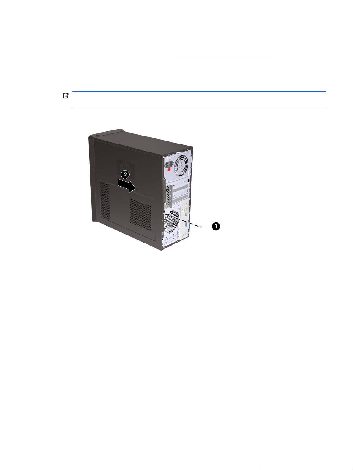
Access Panel
Prepare the computer for disassembly (
1.
2. Loosen the screw (1) that secures the access panel to the computer chassis.
3. Slide the access panel back (2) about 1.3 cm (1/2 inch), then lift it off the unit.
NOTE: You may want to lay the computer on its side to install internal parts. Be sure the side
with the access panel is facing up.
Figure 5-1 Removing the Computer Access Panel
Preparation for Disassembly on page 42).
To replace the access panel, reverse the removal steps.
Access Panel
43
Page 54

Front Bezel
Prepare the computer for disassembly (
1.
Remove the access panel (
2.
3. Press outward on the three latches on the right side of the bezel (1), then rotate the right side of
the bezel off the chassis (2) followed by the left side.
Figure 5-2 Removing the Front Bezel
Access Panel on page 43).
Preparation for Disassembly on page 42).
NOTE: The appearance of the front bezel may vary.
To reinstall the front bezel, reverse the removal procedure.
44 Chapter 5 Removal and Replacement Procedures Minitower (MT) Chassis
Page 55

Bezel Blanks
On some models, there are bezel blanks covering the 3.5-inch and 5.25-inch external drive bays that
need to be removed before installing a drive. To remove a bezel blank:
Remove the front bezel (
1.
To remove the lower 5.25-inch bezel blank, gently twist and pull on the bezel blank until it breaks
2.
free from the front bezel (1), then discard the bezel blank. If the blank needs to be replaced at a
later date, you can order a replacement blank from HP.
To remove the 3.5-inch bezel blank, press the two retaining tabs towards the outer left edge of the
3.
bezel (2) and pull the bezel blank inwards to free it from the front bezel (3).
Figure 5-3 Removing a Bezel Blank
Front Bezel on page 44).
Replace the front bezel.
4.
Memory
The computer comes with double data rate 3 synchronous dynamic random access memory (DDR3SDRAM) dual inline memory modules (DIMMs).
DDR3-SDRAM DIMMs
The memory sockets on the system board can be populated with up to four industry-standard DIMMs.
These memory sockets are populated with at least one preinstalled DIMM. To achieve the maximum
memory support, you can populate the system board with up to either 8 GB or 16 GB of memory
configured in a high-performing dual channel mode, depending on model.
Model Number Maximum Memory
HP Pro 3120 8 GB
HP Pro 3125 16 GB
HP Pro 3130 16 GB
Bezel Blanks
45
Page 56

For proper system operation, the DDR3-SDRAM DIMMs must be:
industry-standard 240-pin
●
unbuffered non-ECC PC3-10600 DDR3-1333 MHz-compliant
●
1.5 volt DDR3-SDRAM DIMMs
●
The DDR3-SDRAM DIMMs must also:
support CAS latency 9 DDR3 1333 MHz (9-9-9 timing)
●
contain the mandatory JEDEC SPD information
●
In addition, the computer supports:
512-Mbit, 1-Gbit, and 2-Gbit non-ECC memory technologies
●
single-sided and double-sided DIMMs
●
DIMMs constructed with x8 and x16 DDR devices; DIMMs constructed with x4 SDRAM are not
●
supported
NOTE: The system will not operate properly if you install unsupported DIMMs.
The system will automatically operate in single channel mode, dual channel mode, or flex mode,
depending on how the DIMMs are installed.
The system will operate in single channel mode if the DIMM sockets are populated in one channel
●
only.
The system will operate in a higher-performing dual channel mode if the total memory capacity of
●
the DIMMs in Channel A is equal to the total memory capacity of the DIMMs in Channel B. The
technology and device width can vary between the channels. For example, if Channel A is
populated with two 1-GB DIMMs and Channel B is populated with one 2-GB DIMM, the system
will operate in dual channel mode.
The system will operate in flex mode if the total memory capacity of the DIMMs in Channel A is
●
not equal to the total memory capacity of the DIMMs in Channel B. In flex mode, the channel
populated with the least amount of memory describes the total amount of memory assigned to dual
channel and the remainder is assigned to single channel. For optimal speed, the channels should
be balanced so that the largest amount of memory is spread between the two channels. If one
channel will have more memory than the other, the larger amount should be assigned to Channel
A. For example, if you are populating the sockets with one 2-GB DIMM, and three 1-GB DIMMs,
Channel A should be populated with the 2-GB DIMM and one 1-GB DIMM, and Channel B should
be populated with the two 1-GB DIMMs. With this configuration, 4 GB will run as dual channel
and 1 GB will run as single channel.
In any mode, the maximum operational speed is determined by the slowest DIMM in the system.
●
46 Chapter 5 Removal and Replacement Procedures Minitower (MT) Chassis
Page 57

Populating DIMM Sockets
There are four DIMM sockets on the system board, with two sockets per channel.
DIMM Socket Locations – HP Pro 3120
When installing memory modules:
If installing only one memory module, install it in DIMM1.
●
If installing 2 memory modules:
●
2 matching memory modules - install in DIMM1 and DIMM3.
◦
2 non-matching memory modules - install in DIMM1 and DIMM3. Install the larger (GB)
◦
module in DIMM1 and smaller (MB) module in DIMM3.
Memory
47
Page 58

If installing 3 memory modules:
●
3 matching memory modules - install in DIMM1, DIMM3, and DIMM2.
◦
2 matching memory modules and 1 non-matching memory module of smaller size (MB) than
◦
combined matching modules (example: 2x2GB and 1x1GB) - install the matching pair in
DIMM1 and DIMM2 and smaller (MB) module in DIMM2.
If installing 4 memory modules:
●
4 matching memory modules - install in DIMM1, DIMM3, DIMM2, and DIMM4.
◦
3 matching memory modules and 1 non-matching memory module of smaller size (MB) than
◦
combined matching modules (example: 3x2GB & 1x1GB) -install the matching pair in
DIMM2, DIMM4, and DIMM1 and smaller (MB) module in DIMM3.
Figure 5-4 DIMM Socket Locations – HP Pro 3120
Table 5-1 DIMM Socket Locations – HP Pro 3120
Item Description Socket Color Insertion Order
1 XMM1 socket, Channel A
(populate first)
2 XMM2 socket, Channel B Blue 3
3 XMM3 socket, Channel A Black 2
4 XMM4 socket, Channel B Blue 4
NOTE: A DIMM must occupy the XMM1 socket.
Black 1
48 Chapter 5 Removal and Replacement Procedures Minitower (MT) Chassis
Page 59

DIMM Socket Locations – HP Pro 3125
When installing memory modules:
If installing only one memory module, install it in DIMM3.
●
If installing 2 memory modules:
●
2 matching memory modules - install in DIMM3 and DIMM4.
◦
2 non-matching memory modules - install in DIMM3 and DIMM4. Install the larger (GB)
◦
module in DIMM3 and smaller (MB) module in DIMM4.
If installing 3 memory modules:
●
3 matching memory modules - install in DIMM3, DIMM4, and DIMM1.
◦
2 matching memory modules and 1 non-matching memory module of smaller size (MB) than
◦
combined matching modules (example: 2x2GB and 1x1GB) - install the matching pair in
DIMM3 and DIMM4 and smaller (MB) module in DIMM1.
If installing 4 memory modules:
●
4 matching memory modules - install in DIMM3, DIMM4, DIMM1, and DIMM2.
◦
3 matching memory modules and 1 non-matching memory module of smaller size (MB) than
◦
combined matching modules (example: 3x2GB & 1x1GB) -install the matching pair in
DIMM3, DIMM4, and DIMM1 and smaller (MB) module in DIMM2.
Figure 5-5 DIMM Socket Locations – HP Pro 3125
Memory
49
Page 60

Table 5-2 DIMM Socket Locations – HP Pro 3125
Item Description Socket Color Insertion Order
1 XMM1 socket, Channel B Blue 3
2 XMM2 socket, Channel B Blue 4
3 XMM3 socket, Channel A
(populate first)
4 XMM4 socket, Channel A Black 2
NOTE: A DIMM must occupy the XMM3 socket.
Black 1
DIMM Socket Locations – HP Pro 3130
When installing memory modules:
If installing only one memory module, install it in DIMM2.
●
If installing 2 memory modules:
●
2 matching memory modules - install in DIMM2 and DIMM4.
◦
2 non-matching memory modules - install in DIMM2 and DIMM4. Install the larger (GB)
◦
module in DIMM2 and smaller (MB) module in DIMM4.
If installing 3 memory modules:
●
3 matching memory modules - install in DIMM2, DIMM4, and DIMM1.
◦
2 matching memory modules and 1 non-matching memory module of smaller size (MB) than
◦
combined matching modules (example: 2x2GB and 1x1GB) - install the matching pair in
DIMM2 and DIMM4 and smaller (MB) module in DIMM1.
If installing 4 memory modules:
●
4 matching memory modules - install in DIMM2, DIMM4, DIMM1, and DIMM3.
◦
3 matching memory modules and 1 non-matching memory module of smaller size (MB) than
◦
combined matching modules (example: 3x2GB & 1x1GB) -install the matching pair in
DIMM2, DIMM4, and DIMM1 and smaller (MB) module in DIMM3.
50 Chapter 5 Removal and Replacement Procedures Minitower (MT) Chassis
Page 61

Figure 5-6 DIMM Socket Locations – HP Pro 3130
Table 5-3 DIMM Socket Locations – HP Pro 3130
Item Description Socket Color Insertion Order
1 XMM1 socket, Channel B Black 3
2 XMM2 socket, Channel B
(populate first)
3 XMM3 socket, Channel A Black 4
4 XMM4 socket, Channel A Blue 2
NOTE: A DIMM must occupy the XMM2 socket.
Blue 1
Memory
51
Page 62

Installing Memory Modules
CAUTION: You must disconnect the power cord and wait approximately 30 seconds for the power
to drain before adding or removing memory modules. Regardless of the power-on state, voltage is
always supplied to the memory modules as long as the computer is plugged into an active AC outlet.
Adding or removing memory modules while voltage is present may cause irreparable damage to the
memory modules or system board.
The memory module sockets have gold-plated metal contacts. When upgrading the memory, it is
important to use memory modules with gold-plated metal contacts to prevent corrosion and/or
oxidation resulting from having incompatible metals in contact with each other.
Static electricity can damage the electronic components of the computer or optional cards. Before
beginning these procedures, ensure that you are discharged of static electricity by briefly touching a
grounded metal object.
When handling a memory module, be careful not to touch any of the contacts. Doing so may damage
the module.
Prepare the computer for disassembly (
1.
Remove the access panel (
2.
Locate the memory module sockets on the system board.
3.
WARNING! To reduce risk of personal injury from hot surfaces, allow the internal system
components to cool before touching.
Access Panel on page 43).
Preparation for Disassembly on page 42).
52 Chapter 5 Removal and Replacement Procedures Minitower (MT) Chassis
Page 63

4. Open both latches of the memory module socket (1), and insert the memory module into the
socket (2).
Figure 5-7 Installing a DIMM
NOTE: A memory module can be installed in only one way. Match the notch on the module with
the tab on the memory socket.
A DIMM must occupy the DIMM1 socket. Always populate the blue sockets before the black
sockets in each channel.
To create a dual-channel memory configuration, the memory capacity of Channel A must equal the
memory capacity of Channel B. Refer to
Populating DIMM Sockets on page 47 for more
information.
Push the DIMM module down firmly into the socket, ensuring that the module is fully inserted and
5.
properly seated. The DIMM must be pushed all the way down into the socket and sit evenly in the
socket to avoid memory corruption. Make sure the latches are in the closed position (3).
Repeat steps 4 and 5 to install any additional modules.
6.
Replace the computer access panel.
7.
Reconnect the power cord and any external devices, then turn on the computer. The computer
8.
should automatically recognize the additional memory when you turn on the computer.
Lock any security devices that were disengaged when the access panel was removed.
9.
Memory
53
Page 64

Expansion Cards
The HP Pro 3120, HP Pro 3125, and HP Pro 3130 all have three PCI Express x1 expansion slots and
one PCI Express x16 expansion slot. The expansion slots accommodate full-height or half-height
expansion cards.
Expansion Slot Locations
Figure 5-8 Expansion Slot Locations – HP Pro 3120
54 Chapter 5 Removal and Replacement Procedures Minitower (MT) Chassis
Page 65

Figure 5-9 Expansion Slot Locations – HP Pro 3125
Figure 5-10 Expansion Slot Locations – HP Pro 3130
Expansion Cards
55
Page 66

Table 5-4 Expansion Slot Locations
Item Description
1 PCI Express x1 expansion slot
2 PCI Express x1 expansion slot
3 PCI Express x1 expansion slot
4 PCI Express x16 expansion slot
NOTE: You can install a PCI Express x1, x4, x8, or x16 expansion card in the PCI Express x16
expansion slot.
To remove, replace, or add an expansion card:
Prepare the computer for disassembly (
1.
Remove the access panel (
2.
Locate the correct vacant expansion socket on the system board and the corresponding expansion
3.
Access Panel on page 43).
Preparation for Disassembly on page 42).
slot on the back of the computer chassis.
On the rear of the computer, a slot cover lock secures the expansion card brackets in place.
4.
Remove the screw from the slot cover lock then slide the slot cover lock up to remove it from the
chassis.
Figure 5-11 Opening the Slot Cover Lock
Before installing an expansion card, remove the expansion slot cover or the existing expansion
5.
card.
56 Chapter 5 Removal and Replacement Procedures Minitower (MT) Chassis
Page 67

NOTE: Before removing an installed expansion card, disconnect any cables that may be
attached to the expansion card.
If you are installing an expansion card in a vacant socket, you must use a flatblade
a.
screwdriver to pry out the metal shield on the rear panel that covers the expansion slot. Be
sure to remove the appropriate shield for the expansion card you are installing.
Figure 5-12 Removing an Expansion Slot Cover
If you are removing a standard PCI Express x1 card, hold the card at each end, and
b.
carefully rock it back and forth until the connectors pull free from the socket. Pull the
expansion card straight up from the socket then away from the inside of the chassis to release
it from the chassis frame. Be sure not to scrape the card against the other components.
Figure 5-13 Removing a PCI Express x1 Expansion Card
Expansion Cards
57
Page 68

If you are removing a PCI Express x16 card, pull the retention arm on the back of the
c.
expansion socket away from the card and carefully rock the card back and forth until the
connectors pull free from the socket. Be sure not to scrape the card against the other
components.
Figure 5-14 Removing a PCI Express x16 Expansion Card
Store the removed card in anti-static packaging.
6.
If you are not installing a new expansion card, install an expansion slot cover to close the open
7.
slot.
CAUTION: After removing an expansion card, you must replace it with a new card or
expansion slot cover for proper cooling of internal components during operation.
58 Chapter 5 Removal and Replacement Procedures Minitower (MT) Chassis
Page 69

To install a new expansion card, hold the card just above the expansion socket on the system
8.
board then move the card toward the rear of the chassis so that the bottom of the bracket on the
card slides into the small slot on the chassis. Press the card straight down into the expansion
socket on the system board.
Figure 5-15 Installing an Expansion Card
NOTE: When installing an expansion card, press firmly on the card so that the whole connector
seats properly in the expansion card slot.
Replace the slot cover lock and secure it in place with the screw that was previously removed.
9.
Figure 5-16 Securing the Expansion Cards and Slot Covers
Connect external cables to the installed card, if needed. Connect internal cables to the system
10.
board, if needed.
Replace the computer access panel.
11.
Expansion Cards
59
Page 70

Reconnect the power cord and any external devices, then turn on the computer.
12.
Lock any security devices that were disengaged when the access panel was removed.
13.
Reconfigure the computer, if necessary. Refer to
14.
instructions on using Computer Setup.
Cable Management
Always follow good cable management practices when working inside the computer.
Keep cables away from major heat sources like the heat sink.
●
Do not jam cables on top of expansion cards or memory modules. Printed circuit cards like these
●
are not designed to take excessive pressure on them.
Some flat ribbon cables come prefolded. Never change the folds on these cables.
●
Never bend a SATA data cable tighter than a 30 mm (1.18 in) radius.
●
Never crease a SATA data cable.
●
Do not rely on components like the drive cage, power supply, or computer cover to push cables
●
down into the chassis. Always position the cables to lay properly by themselves.
When removing the power supply power cable from the 24-pin connector on the system board, always
follow these steps:
1. Squeeze on the top of the retaining latch attached to the cable end of the connector (1).
Computer Setup (F10) Utility on page 4 for
2. Grasp the cable end of the connector and pull it straight up (2).
CAUTION: Always pull the connector - NEVER pull on the cable. Pulling on the cable could
damage the cable and result in a failed power supply.
60 Chapter 5 Removal and Replacement Procedures Minitower (MT) Chassis
Page 71

Cable Connections
HP Pro 3120
System board connectors are color-coded to make it easier to find the proper connection.
Connector Name Connector Color Description
ATX PWR white Power supply, 24-pin
ATX_CPU white Power supply, 4-pin
CHASSIS_FAN1 brown Chassis fan
CPU_FAN white Heat sink fan
F_USB2 black Media card reader
J_PANEL black Power switch
FRNT AUD yellow Front I/O audio
F_USB1 white Front I/O USB
SATA1 dark blue Primary hard drive
SATA2 white Primary optical drive
SATA3 light blue Second hard drive
SATA4 orange Second optical drive
HP Pro 3125
System board connectors are color-coded to make it easier to find the proper connection.
Connector Name Connector Color Description
P15 white Power supply, 24-pin
PU521 white Power supply, 4-pin
SYS_FAN brown Chassis fan
CPU_FAN white Heat sink fan
J18 black Power switch
F_AUDIO yellow Front I/O audio
F_USB1 white Front I/O USB
F_USB3 white Media card reader
SATA1 dark blue Primary hard drive
SATA2 white Primary optical drive
SATA3 light blue Second hard drive
SATA4 orange Second optical drive
Cable Management
61
Page 72

HP Pro 3130
System board connectors are color-coded to make it easier to find the proper connection.
Connector Name Connector Color Description
ATX1 white Power supply, 24-pin
PWR1 white Power supply, 4-pin
SYS_FAN1 brown Chassis fan
CPU_FAN1 white Heat sink fan
JPF1 black Power switch
JAUD1 yellow Front I/O audio
JUSB2 white Front I/O USB
JUSB1 white Media card reader
JJ1394_1 red 1394 connector
SATA1 dark blue Primary hard drive
SATA2 white Primary optical drive
SATA3 light blue Second hard drive
SATA4 orange Second optical drive
62 Chapter 5 Removal and Replacement Procedures Minitower (MT) Chassis
Page 73
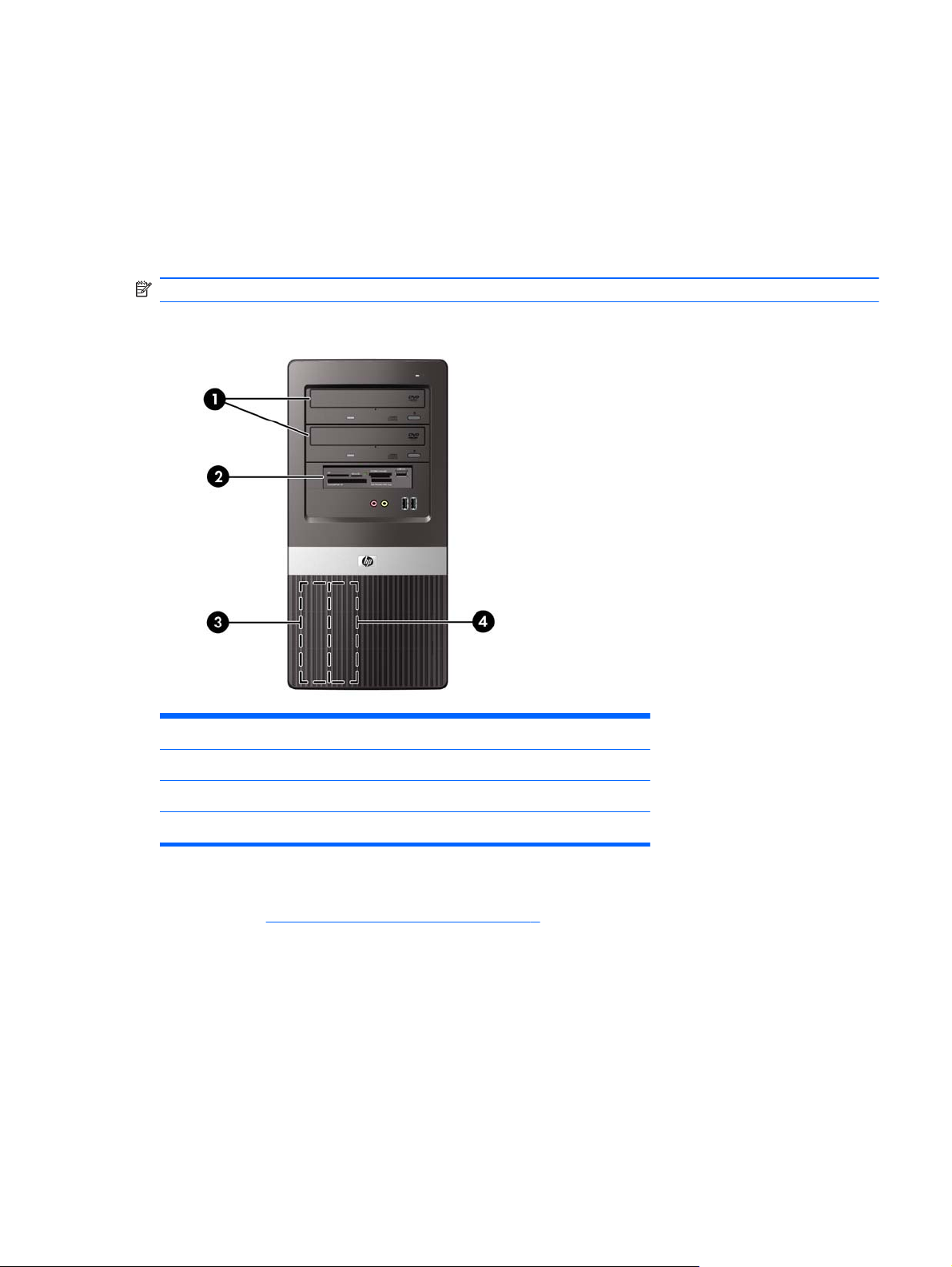
Drives
The computer supports up to five drives that may be installed in various configurations.
This section describes the procedure for replacing or upgrading the storage drives. A Torx T-15
screwdriver is needed to remove and install the guide screws on a drive.
Drive Positions
NOTE: Front bezel appearance may vary.
Figure 5-17 Drive Positions
1 Two 5.25-inch external drive bays for optional drives (optical drives shown)
2 One 3.5-inch external drive bay for optional drive (media card reader shown)
3 Primary 3.5-inch internal hard drive bay
4 Secondary 3.5-inch internal hard drive bay for optional hard drive
To verify the type, size, and capacity of the storage devices installed in the computer, run Computer
Setup. Refer to
Computer Setup (F10) Utility on page 4 for more information.
Drives
63
Page 74

Installing Additional Drives
When installing additional drives, follow these guidelines:
The primary Serial ATA (SATA) hard drive must be connected to the dark blue primary SATA
●
connector on the system board.
Connect the first SATA optical drive to the white SATA connector on the system board.
●
Always populate the dark blue and white connectors before the light blue and orange connectors.
●
The system does not support Parallel ATA (PATA) optical drives or PATA hard drives.
●
CAUTION: To prevent loss of work and damage to the computer or drive:
If you are inserting or removing a drive, shut down the operating system properly, turn off the
computer, and unplug the power cord. Do not remove a drive while the computer is on or in standby
mode.
Before handling a drive, ensure that you are discharged of static electricity. While handling a drive,
avoid touching the connector.
Handle a drive carefully; do not drop it.
Do not use excessive force when inserting a drive.
Avoid exposing a hard drive to liquids, temperature extremes, or products that have magnetic fields
such as monitors or speakers.
If a drive must be mailed, place the drive in a bubble-pack mailer or other protective packaging and
label the package “Fragile: Handle With Care.”
64 Chapter 5 Removal and Replacement Procedures Minitower (MT) Chassis
Page 75

System Board Drive Connections
Refer to the following illustrations and tables to identify the system board drive connectors.
System Board Drive Connections
Figure 5-18 System Board Drive Connections – HP Pro 3120
Table 5-5 System Board Drive Connections – HP Pro 3120
No. System Board Connector System Board Label Color
1 SATA0 SATA0 dark blue
2 SATA1 SATA1 white
3 SATA2 SATA2 light blue
4 SATA3 SATA3 orange
5 Media Card Reader F_USB2 white
Drives
65
Page 76

Figure 5-19 System Board Drive Connections – HP Pro 3125
Table 5-6 System Board Drive Connections – HP Pro 3125
No. System Board Connector System Board Label Color
1 SATA1 SATA1 dark blue
2 SATA2 SATA2 white
3 SATA3 SATA3 light blue
4 SATA4 SATA4 orange
5 Media Card Reader F_USB1 white
66 Chapter 5 Removal and Replacement Procedures Minitower (MT) Chassis
Page 77

Figure 5-20 System Board Drive Connections – HP Pro 3130
Table 5-7 System Board Drive Connections – HP Pro 3130
No. System Board Connector System Board Label Color
1 SATA1 SATA1 dark blue
2 SATA2 SATA2 white
3 SATA3 SATA3 light blue
4 SATA4 SATA4 orange
5 Media Card Reader JUSB1 white
Drives
67
Page 78

Removing an Optical Drive
CAUTION: All removable media should be taken out of a drive before removing the drive from the
computer.
To remove an optical drive:
Prepare the computer for disassembly (
1.
Remove the access panel (
2.
Remove the front bezel (
3.
4. Disconnect the power cable (1) and data cable (2) from the rear of the optical drive.
Figure 5-21 Disconnecting the Power and Data Cables
5. Pull out the drive latch and swing it to the left(1), then slide the drive out of the front of the chassis
(2).
Access Panel on page 43).
Front Bezel on page 44).
Preparation for Disassembly on page 42).
Figure 5-22 Removing the Optical Drive
Reverse the removal procedure to install an optical drive.
If installing a new optical drive in a previously unused drive bay, first remove the break-away EMF
shield from the front of the PC.
68 Chapter 5 Removal and Replacement Procedures Minitower (MT) Chassis
Page 79

When inserting an optical drive, pull out on the drive latch and insert its peg into the hole marked 2,
and then slide the drive back until it locks into position.
Removing an Internal 3.5-inch Hard Drive
NOTE: Before you remove the old hard drive, be sure to back up the data from the old hard drive so
that you can transfer the data to the new hard drive. Also, if you are replacing the primary hard drive,
make sure you have created a Recovery Disc Set to restore the operating system, software drivers, and
any software applications that were preinstalled on the computer. If you do not have this CD set, select
Start > HP Backup and Recovery and create it now.
Prepare the computer for disassembly (
1.
Remove the access panel (
2.
Remove the two screws that secure the hard drive cage to the chassis.
3.
Figure 5-23 Removing the Hard Drive Cage Screws
Access Panel on page 43).
Preparation for Disassembly on page 42).
Drives
69
Page 80

4. Push down the latch on the side of the hard drive cage (1), then slide the hard drive cage away
from the bottom of the chassis (2) as shown below.
Figure 5-24 Releasing the Hard Drive Cage
Lift the hard drive cage out of the chassis.
5.
Figure 5-25 Removing the Hard Drive Cage
70 Chapter 5 Removal and Replacement Procedures Minitower (MT) Chassis
Page 81

6. Disconnect the power cable (1) and data cable (2) from the back of the hard drive.
Figure 5-26 Disconnecting the Hard Drive Cables
7. Remove the four screws that secure the hard disk drive to the hard drive cage (1), then slide the
hard disk drive out of the hard drive cage (2).
Figure 5-27 Removing the Hard Drive
Drives
71
Page 82

Front I/O and USB Panel Housing Assembly
Prepare the computer for disassembly (
1.
Remove the access panel (
2.
Lay the computer on its side with the front facing toward you.
3.
Remove the front bezel (
4.
Unplug the two cables from the yellow and white system board connectors on the system board.
5.
Remove the screw that secures the housing to the chassis, and then pull the assembly away from
6.
the chassis while guiding the cables through the hole in the chassis.
Access Panel on page 43)
Front Bezel on page 44).
Preparation for Disassembly on page 42).
To install the housing assembly, reverse the removal procedures.
When installing the assembly, note that the assembly has hooks that fit into slots in the chassis, as
shown in the following images.
72 Chapter 5 Removal and Replacement Procedures Minitower (MT) Chassis
Page 83

Power Switch/LED Assembly
Prepare the computer for disassembly (
1.
Remove the access panel (
2.
Lay the computer on its side with the front facing toward you.
3.
Remove the front bezel (
4.
Remove the optical drive (
5.
Disconnect the braided cables from the black system board connector.
6.
Remove the cable from the clips in the optical drive cage.
7.
Press the tab on the top of the power switch to disengage it from the chassis, lift the switch upward
8.
to disengage the tab at the bottom of the switch from the chassis, and then pull the power switch
away from the chassis while guiding the wires through the hole in the chassis.
Access Panel on page 43).
Front Bezel on page 44).
Removing an Optical Drive on page 68).
Preparation for Disassembly on page 42).
Power Switch/LED Assembly
73
Page 84

Remove the power switch cable from the clips located in the optical drive bay on the inside of the
9.
chassis.
To install the power switch/LED assembly, reverse the removal procedures.
System Fan
Prepare the computer for disassembly (
1.
Remove the access panel (
2.
Lay the computer on its side with the rear facing toward you.
3.
Disconnect the cable from the red/brown system board connector.
4.
Remove the four Phillips screws that secure the fan to the chassis, rotate the top of the fan forward,
5.
and then remove the fan from the chassis.
Preparation for Disassembly on page 42).
Access Panel on page 43).
NOTE: Rear I/O panel appearance may vary.
To install the fan, reverse the removal procedures.
74 Chapter 5 Removal and Replacement Procedures Minitower (MT) Chassis
Page 85

NOTE: Arrows on the side of the fan indicate the direction the fan blows. Make sure the fan is
oriented so air flows out of the chassis and the system fan cable exits from the bottom right side of the
system fan.
Heat sink assembly
There are two different types of heat sinks available. One uses four Torx screws to secure it to the
system board. The other uses a latch and clips. Both heat sink types are shown in the following section.
Prepare the computer for disassembly (
1.
Remove the access panel (
2.
Lay the computer on its side with the rear facing toward you.
3.
4. Disconnect the heat sink fan control cable (1) from the white system board connector.
If the computer uses a heat sink secured with four Torx screws, loosen the four captive torx T15
5.
screws (2) that secure the heat sink to the system board.
Access Panel on page 43).
Preparation for Disassembly on page 42).
6. If the heat sink is secured using a lever mechanism, lift the lever (1) that secures the heat sink latch
to the heat sink bracket attached to the system board.
7. After loosening the lever, press downward on the lever to release the square clip (2) from the tab
on the heat sink bracket.
8. Use the lever to maneuver the square clip on the opposite side on the heat sink (3) free from the
tab on the heat sink bracket.
Heat sink assembly
75
Page 86

Lift the heat sink from the processor and set it on its side to keep from contaminating the work area
9.
with thermal grease.
To install a heat sink, reverse the removal procedures.
CAUTION: For heat sinks secured with retaining screws, tighten the screws in diagonally opposite
pairs (as in an X) to evenly seat the heat sink to the processor. This is especially important as the pins
on the socket are very fragile and any damage to them may require replacing the system board.
When installing the heat sink, recommended torque = 4-6 in-lbs.
NOTE: When installing a new heat sink, remove protective plastic cover from thermal pad on bottom
of heat-sink.
When installing a heat sink, if sufficient pressure is not applied during heat sink installation, heat sink
may cant (tilt), causing boot errors.
CAUTION: Do not apply pressure to the heat sink fan blades or center area. This may damage the
fan. When installing the heat sink, apply pressure only to fan frame.
Processor
The computer may use an Intel or an AMD processor. Removal and replacement procedures vary
depending on processor type.
Prepare the computer for disassembly (
1.
Preparation for Disassembly on page 42).
Remove the access panel (
2.
Lay the computer on its side with the rear facing toward you.
3.
Disconnect the heat sink control cable from the system board and remove the heatsink
4.
assembly on page 75).
76 Chapter 5 Removal and Replacement Procedures Minitower (MT) Chassis
Access Panel on page 43).
Heat sink
Page 87
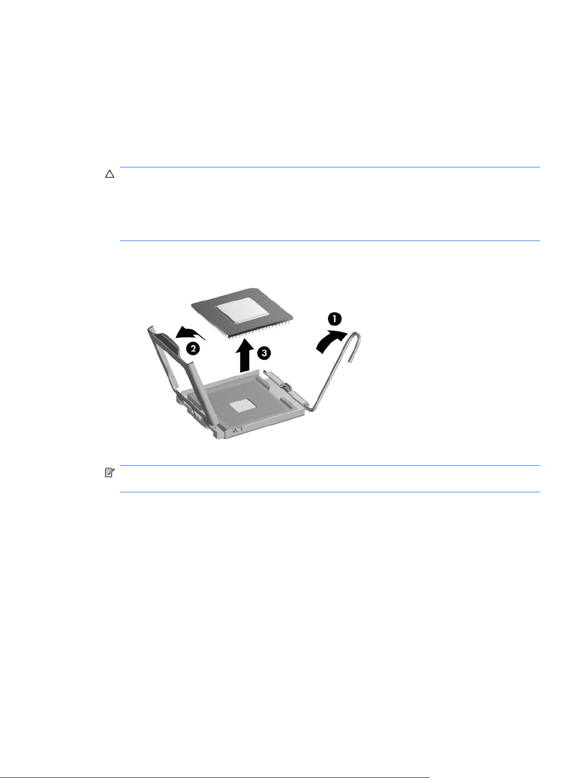
If the computer has an Intel processor, go to steps 7 – 9.
5.
If the computer has an AMD processor, go to steps 10 – 11.
6.
7. Rotate the locking lever to its full open position (1).
8. Raise and rotate the microprocessor retainer to its full open position (2).
9. Carefully lift the processor from the socket (3).
CAUTION: Do NOT handle the pins in the processor socket. These pins are very fragile and
handling them could cause irreparable damage. Once pins are damaged it may be necessary to
replace the system board.
CAUTION: The heat sink must be installed within 24 hours of installing the processor to prevent
damage to the processor’s solder connections.
NOTE: Steps 10 – 11 are for computers with AMD processors. See steps 7 – 9 for instructions
to remove Intel processors.
10. Rotate the locking lever to its full open position (1).
Processor
77
Page 88
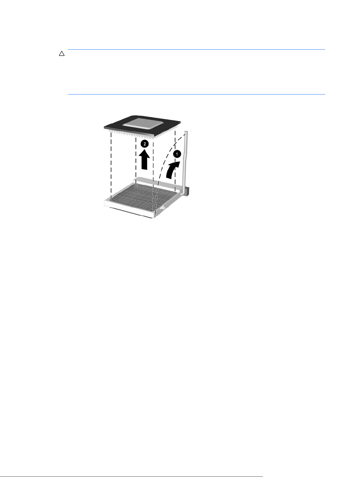
11. Carefully lift the processor from the socket (2).
CAUTION: Do NOT handle the pins in the processor socket. These pins are very fragile and
handling them could cause irreparable damage. Once pins are damaged it may be necessary to
replace the system board.
CAUTION: The heat sink must be installed within 24 hours of installing the processor to prevent
damage to the processor’s solder connections.
To install a new processor:
Place the processor in its socket. Make sure the gold triangle on the processor is aligned with the
1.
triangle on the socket.
If installing an Intel processor, close the retainer.
2.
Secure the locking lever.
3.
If reusing the existing heat sink, go to step 4.
If using a new heat sink, go to step 7.
If reusing the existing heat sink, clean the bottom of the heat sink with the alcohol pad provided in
4.
the spares kit.
Apply the thermal grease provided in the spares kit to the top of the processor and install the heat
5.
sink atop the processor.
Go to step 8.
6.
If using a new heat sink, remove the protective covering from the bottom of the heat sink and
7.
place it in position atop the processor.
Secure the heat sink to the system board, and then attach the heat sink control cable to the system
8.
board, if applicable.
78 Chapter 5 Removal and Replacement Procedures Minitower (MT) Chassis
Page 89

CAUTION: Heat sink retaining screws should be tightened in diagonally opposite pairs (as in
an X) to evenly seat the heat sink on the processor. This is especially important as the pins on the
socket are very fragile and any damage to them may require replacing the system board.
NOTE: After installing a new processor onto the system board, always update the system ROM
to ensure that the latest version of the BIOS is being used on the computer. The latest system ROM
BIOS can be found on the Web at:
Power Supply
The power supply is secured to the back of the chassis with four Torx screws. Additionally, the power
supply is held in place by a lever on the interior chassis floor.
WARNING! Voltage is always present on the system board when the computer is plugged into an
active AC outlet. To avoid possible personal injury and damage to the equipment the power cord
should be disconnected from the computer and/or the AC outlet before opening the computer.
Table 5-8 Model 3120 power supply cable connections
Power supply connector label Connects to
P1 Main power connector (24 pin)
P7 CPU power connector (4 pin)
http:\\h18000.www1.hp.com/support/files.
P4 Hard drive 1
P3 Optical drive 1
P5 Hard drive 2
P2 Optical drive 2
Table 5-9 Model 3125 power supply cable connections
Power supply connector label Connects to
P1 Main power connector (24 pin)
P6 CPU power connector (4 pin)
P4 Hard drive 1
P3 Optical drive 1
P5 Hard drive 2
P2 Optical drive 2
Table 5-10 Model 3130 power supply cable connections
Power supply connector label Connects to
P1 Main power connector (24 pin)
P7 CPU power connector (4 pin)
Power Supply
79
Page 90

Table 5-10 Model 3130 power supply cable connections
(continued)
P4 Hard drive 1
P3 Optical drive 1
P5 Hard drive 2
P2 Optical drive 2
NOTE: If the power supply includes a voltage select switch, make sure to set the red switch to the
setting (230 V or 115 V) appropriate for the country in which the computer is used. See the table at the
end of this section for a list of settings. Spare power supplies normally arrive set for 230 V.
Prepare the computer for disassembly (
1.
Remove the access panel (
2.
Lay the computer on its side with the rear facing toward you.
3.
Disconnect all power cables from the mass storage devices and from the system board (two
4.
Access Panel on page 43).
Preparation for Disassembly on page 42).
connectors).
Remove the four screws that secure the power supply to the chassis.
5.
NOTE: Rear appearance varies by model.
80 Chapter 5 Removal and Replacement Procedures Minitower (MT) Chassis
Page 91

Inside of the unit, press the power supply release latch on the chassis base, and then lift up the
6.
rear of the power supply to disengage it from the chassis.
NOTE: System board appearance varies by model.
Slide the power supply toward the front/bottom of the computer, then lift the power supply out of
7.
the computer.
To install the power supply, reverse the removal procedure.
Table 5-11 Country power supply settings
Country Voltage setting Country Voltage setting
Austria 230W Mexico 115W
Australia 230W The Netherlands 230W
Argentina 230W New Zealand 230W
Belgium 230W Portugal 230W
Brazil 230W Norway 230W
Canada 115W People's Republic of China 230W
Caribbean 230W Singapore 230W
Denmark 230W South Korea 230W
Finland 230W Spain 230W
France 230W Sweden 230W
Germany 230W Switzerland 230W
India 230W Taiwan 115W
Italy 230W Thailand 230W
Power Supply
81
Page 92

Table 5-11 Country power supply settings (continued)
Japan 115W The United Kingdom 230W
Latin America 115W The United States 115W
System Board
When replacing the system board, be sure that the following components are removed from the
defective system board and installed on the replacement system board:
Memory modules
●
Processor
●
Expansion cards
●
To remove the system board:
Prepare the computer for disassembly (
1.
Remove the access panel (
2.
Lay the computer on its side with the rear facing toward you.
3.
Remove the front bezel (
4.
Remove an expansion cards (
5.
Disconnect the power, and data cables from the back of all installed drives.
6.
Disconnect all cables from the system board.
7.
8. Remove the eight screws that secure the system board to the chassis (1).
Access Panel on page 43).
Front Bezel on page 44).
Expansion Cards on page 54).
Preparation for Disassembly on page 42).
82 Chapter 5 Removal and Replacement Procedures Minitower (MT) Chassis
Page 93

9. Slide the system board toward the front of the chassis (2), and then lift it up and out of the chassis.
NOTE: System board appearance varies by model.
To install the system board, reverse the removal procedure.
Note the following when installing a system board:
To insure correct installation while fastening the first two screws, press the system board firmly in
●
place against the rear I/O panel so that the system board screw holes are aligned to the mounting
holes in the chassis.
When installing a system board, align the ports on the rear of the system board to cutouts in the
●
rear of the chassis (keep EMI tabs on top of the connectors), and firmly slide toward the chassis
rear until system board screw holes are aligned to mounting holes in the chassis.
Ensure ground fingers make contact with the connectors on the system board and are not
●
damaged.
When installing the system board, recommended torque = 4-6 in-lbs.
●
When replacing the system board, you must also change the chassis serial number in the BIOS.
●
After installing a new system board, always update the system ROM to ensure that the latest
●
version of the BIOS is being used on the computer. The latest system ROM BIOS can be found at:
http:\\h18000.www1.hp.com/support/files.
System Board
83
Page 94

Battery
The battery that comes with your computer provides power to the real-time clock and has a lifetime of
about three years. When replacing the battery, use a battery equivalent to the battery originally
installed on the computer. The computer comes with a 3-volt lithium coin cell battery.
NOTE: The lifetime of the lithium battery can be extended by plugging the computer into a live AC
wall socket. The lithium battery is only used when the computer is NOT connected to AC power.
WARNING! This computer contains an internal lithium manganese dioxide battery. There is a risk of
fire and burns if the battery is not handled properly. To reduce the risk of personal injury:
❑
❑
❑
❑
CAUTION: Before replacing the battery, it is important to back up the computer CMOS settings.
When the battery is removed or replaced, the CMOS settings will be cleared. Refer to the
Troubleshooting Guide for information on backing up the CMOS settings.
NOTE: Batteries, battery packs, and accumulators should not be disposed of together with the
general household waste. In order to forward them to recycling or proper disposal, please use the
public collection system or return them to HP, its authorized partners, or its agents.
Do not attempt to recharge the battery.
Do not expose to temperatures higher than 60°C (140°F)
Do not disassemble, crush, puncture, short external contacts, or dispose of in fire or water.
Replace the battery only with the HP/Compaq spare designated for this product.
CAUTION: Static electricity can damage the electronic components of the computer or optional
equipment. Before beginning these procedures, ensure that you are discharged of static electricity by
briefly touching a grounded metal object.
Prepare the computer for disassembly (
1.
Remove the access panel (
2.
NOTE: It may be necessary to remove an expansion card to gain access to the battery.
Locate the battery and battery holder on the system board.
3.
Access Panel on page 43).
Preparation for Disassembly on page 42).
84 Chapter 5 Removal and Replacement Procedures Minitower (MT) Chassis
Page 95

Type 1 Battery Holder
Lift the battery out of its holder.
1.
Slide the replacement battery into position, positive side up.
2.
The battery holder automatically secures the battery in the proper position.
3.
Replace the computer access panel.
4.
Plug in the computer and turn on power to the computer.
5.
Reset the date and time, your passwords, and any special system setups, using Computer Setup.
6.
Refer to the Computer Setup (F10) Utility Guide.
Type 2 Battery Holder
To release the battery from its holder, squeeze the metal clamp that extends above one edge of
1.
the battery. When the battery pops up, lift it out (1).
To insert the new battery, slide one edge of the replacement battery under the holder’s lip with the
2.
positive side up (2). Push the other edge down until the clamp snaps over the other edge of the
battery.
Replace the computer access panel.
3.
Battery
85
Page 96

Plug in the computer and turn on power to the computer.
4.
Reset the date and time, your passwords, and any special system setups, using Computer Setup.
5.
Refer to the Computer Setup (F10) Utility Guide.
Type 3 Battery Holder
1. Pull back on the clip (1) that holds the battery in place, then remove the battery (2).
Insert the new battery and position the clip back in place.
2.
Replace the computer access panel.
3.
Plug in the computer and turn on power to the computer.
4.
Reset the date and time, your passwords, and any special system setups, using Computer Setup.
5.
Refer to the Computer Setup (F10) Utility Guide.
86 Chapter 5 Removal and Replacement Procedures Minitower (MT) Chassis
Page 97

6 Removal and Replacement
Procedures Small Form Factor (SFF)
Chassis
Adherence to the procedures and precautions described in this chapter is essential for proper service.
After completing all necessary removal and replacement procedures, run the Diagnostics utility to verify
that all components operate properly.
NOTE: Not all features listed in this guide are available on all computers.
Preparation for Disassembly
See Identifying the Chassis, Routine Care, and Disassembly Preparation on page 32 for initial safety
procedures.
Remove/disengage any security devices that prohibit opening the computer.
1.
Close any open software applications.
2.
Exit the operating system.
3.
Remove any compact disc or media card from the computer.
4.
Turn off the computer and any peripheral devices that are connected to it.
5.
CAUTION: Turn off the computer before disconnecting any cables.
Regardless of the power-on state, voltage is always present on the system board as long as the
system is plugged into an active AC outlet. In some systems the cooling fan is on even when the
computer is in the “Standby,” or “Suspend” modes. The power cord should always be
disconnected before servicing a unit.
Disconnect the power cord from the electrical outlet and then from the computer.
6.
Disconnect all peripheral device cables from the computer.
7.
NOTE: During disassembly, label each cable as you remove it, noting its position and routing.
Keep all screws with the units removed.
CAUTION: The screws used in the computer are of different thread sizes and lengths; using the
wrong screw in an application may damage the unit.
Preparation for Disassembly
87
Page 98

Access Panel
Prepare the computer for disassembly (
1.
If the computer is on a stand, remove the computer from the stand.
2.
3. Loosen the thumbscrew (1), and then grasp the handle and remove the panel from the computer
(2).
Figure 6-1 Removing the Access Panel
Preparation for Disassembly on page 87).
To install the access panel, reverse the removal procedure.
88 Chapter 6 Removal and Replacement Procedures Small Form Factor (SFF) Chassis
Page 99

Front Bezel
NOTE: Computer appearance may vary.
Prepare the computer for disassembly (
1.
Remove the access panel (
2.
3. Lift up the three tabs on the side of the bezel (1), then rotate the bezel off the chassis (2).
Figure 6-2 Removing the Front Bezel
To install the front bezel, reverse the removal procedure.
Access Panel on page 88).
Preparation for Disassembly on page 87).
Front Bezel
89
Page 100

Installing Additional Memory
The computer comes with double data rate 3 synchronous dynamic random access memory (DDR3SDRAM) dual inline memory modules (DIMMs).
DIMMs
The memory sockets on the system board can be populated with up to four industry-standard DIMMs.
These memory sockets are populated with at least one preinstalled DIMM. To achieve the maximum
memory support, you can populate the system board with up to either 4 GB, 8 GB, or 16-GB of
memory configured in a high-performing dual channel mode.
Model Number Maximum Memory
HP Pro 2110 4 GB
HP Pro 3120 8 GB
HP Pro 3130 16 GB
DDR3-SDRAM DIMMs
For proper system operation, the DDR3-SDRAM DIMMs must be:
industry-standard 240-pin
●
unbuffered non-ECC PC3-8500 DDR3-1066 MHz-compliant or PC3-10600 DDR3-1333 MHz-
●
compliant
1.5 volt DDR3-SDRAM DIMMs
●
The DDR3-SDRAM DIMMs must also:
support CAS latency 7 DDR3 1066 MHz (7-7-7 timing) and CAS latency 9 DDR3 1333 MHz
●
(9-9-9 timing)
contain the mandatory JEDEC SPD information
●
In addition, the computer supports:
512-Mbit, 1-Gbit, and 2-Gbit non-ECC memory technologies
●
single-sided and double-sided DIMMs
●
DIMMs constructed with x8 and x16 DDR devices; DIMMs constructed with x4 SDRAM are not
●
supported
NOTE: The system will not operate properly if you install unsupported DIMMs.
90 Chapter 6 Removal and Replacement Procedures Small Form Factor (SFF) Chassis
 Loading...