

HP Pro 2000, Pro 2080 Maintenance And Service Manual

Maintenance & Service Guide
HP Pro 2000 Business PCs
HP Pro 2080 Business PCs

© Copyright 2009 Hewlett-Packard
Development Company, L.P. The
information contained herein is subject to
change without notice.
Microsoft and Windows are trademarks of
Microsoft Corporation in the U.S. and other
countries.
The only warranties for HP products and
services are set forth in the express
warranty statements accompanying such
products and services. Nothing herein
should be construed as constituting an
additional warranty. HP shall not be liable
for technical or editorial errors or omissions
contained herein.
This document contains proprietary
information that is protected by copyright.
No part of this document may be
photocopied, reproduced, or translated to
another language without the prior written
consent of Hewlett-Packard Company.
Maintenance & Service Guide
HP Pro 2000 Business PCs
HP Pro 2080 Business PCs
First Edition (November 2009)
Document Part Number: 597664-001

About This Book
WARNING! Text set off in this manner indicates that failure to follow directions could result in bodily
harm or loss of life.
CAUTION: Text set off in this manner indicates that failure to follow directions could result in
damage to equipment or loss of information.
NOTE: Text set off in this manner provides important supplemental information.
iii

iv About This Book

Table of contents
1 Product Features ............................................................................................................................................ 1
Standard Configuration Features ......................................................................................................... 1
Serviceability Features ......................................................................................................................... 2
Front Panel Components ..................................................................................................................... 3
Media Card Reader Components ......................................................................................................... 4
Rear Panel Components ...................................................................................................................... 5
2 Installing and Customizing the Software ...................................................................................................... 6
Installing the Operating System ........................................................................................................... 6
Downloading Microsoft Windows Updates ........................................................................................... 6
Installing or Upgrading Device Drivers (Windows systems) ................................................................. 7
Accessing Disk Image (ISO) Files ........................................................................................................ 7
Protecting the Software ........................................................................................................................ 7
3 Computer Setup (F10) Utility ......................................................................................................................... 8
Computer Setup (F10) Utilities ............................................................................................................. 8
Using Computer Setup (F10) Utilities .................................................................................. 8
Computer Setup—Main ..................................................................................................... 10
Computer Setup—Advanced ............................................................................................. 11
Computer Setup—Boot ...................................................................................................... 12
Computer Setup—Power ................................................................................................... 13
Computer Setup—PC Health ............................................................................................. 13
Computer Setup—Exit ....................................................................................................... 14
4 Serial ATA (SATA) Drive Guidelines and Features .................................................................................... 15
SATA Hard Drives .............................................................................................................................. 15
SATA Hard Drive Cables .................................................................................................................... 15
SATA Data Cable .............................................................................................................. 15
SMART ATA Drives ............................................................................................................................ 16
Hard Drive Capacities ........................................................................................................................ 16
5 Identifying the Chassis, Routine Care, and Disassembly Preparation .................................................... 17
Electrostatic Discharge Information .................................................................................................... 17
v

Generating Static ............................................................................................................... 17
Preventing Electrostatic Damage to Equipment ................................................................ 18
Personal Grounding Methods and Equipment ................................................................... 18
Grounding the Work Area .................................................................................................. 19
Recommended Materials and Equipment .......................................................................... 19
Operating Guidelines .......................................................................................................................... 20
Routine Care ...................................................................................................................................... 21
General Cleaning Safety Precautions ................................................................................ 21
Cleaning the Computer Case ............................................................................................ 21
Cleaning the Keyboard ...................................................................................................... 21
Cleaning the Monitor .......................................................................................................... 22
Cleaning the Mouse ........................................................................................................... 22
Service Considerations ...................................................................................................................... 22
Power Supply Fan ............................................................................................................. 22
Tools and Software Requirements .................................................................................... 22
Screws ............................................................................................................................... 23
Cables and Connectors ..................................................................................................... 23
Hard Drives ........................................................................................................................ 23
Lithium Coin Cell Battery ................................................................................................... 24
6 Removal and Replacement Procedures Microtower (MT) Chassis .......................................................... 25
Preparation for Disassembly .............................................................................................................. 25
Access Panel ...................................................................................................................................... 26
Front Bezel ......................................................................................................................................... 27
Bezel Blanks ....................................................................................................................................... 28
Memory .............................................................................................................................................. 29
DDR3-SDRAM DIMMs ...................................................................................................... 29
Populating DIMM Sockets ................................................................................................. 30
Installing Memory Modules ................................................................................................ 31
Expansion Cards ................................................................................................................................ 33
Cable Management ............................................................................................................................ 37
Cable Connections ............................................................................................................ 38
Drives ................................................................................................................................................. 39
Drive Positions ................................................................................................................... 39
Installing Additional Drives ................................................................................................. 40
System Board Drive Connections ..................................................................... 41
Removing an Optical Drive ............................................................................... 42
Installing an Optical Drive into the 5.25-inch Drive Bay .................................... 43
Removing an External 3.5-inch Drive ................................................................ 44
Installing a Drive into the 3.5-inch External Drive Bay ...................................... 45
Removing an Internal 3.5-inch Hard Drive ........................................................ 46
Installing an Internal 3.5-inch Hard Drive .......................................................... 50
Front I/O and USB Panel Housing Assembly ..................................................................................... 53
vi

Power Switch/LED Assembly ............................................................................................................. 54
System Fan ........................................................................................................................................ 55
Heat sink assembly ............................................................................................................................ 56
Processor ........................................................................................................................................... 57
Power Supply ..................................................................................................................................... 58
System Board ..................................................................................................................................... 60
Battery ................................................................................................................................................ 61
Type 1 Battery Holder ........................................................................................................ 62
Type 2 Battery Holder ........................................................................................................ 62
Type 3 Battery Holder ........................................................................................................ 63
Installing a Security Lock .................................................................................................................... 64
HP/Kensington MicroSaver Security Cable Lock ............................................................... 64
Padlock .............................................................................................................................. 64
HP Business PC Security Lock .......................................................................................... 65
Hood Sensor ...................................................................................................................... 67
HP Chassis Security Kit ..................................................................................................... 68
Appendix A Connector Pin Assignments ...................................................................................................... 69
Ethernet BNC ..................................................................................................................................... 69
USB .................................................................................................................................................... 69
Microphone ......................................................................................................................................... 69
Headphone ......................................................................................................................................... 70
Line-in Audio ...................................................................................................................................... 70
Line-out Audio .................................................................................................................................... 70
4-Pin Power (for CPU) ........................................................................................................................ 70
Monitor ............................................................................................................................................... 71
Serial Interface, Powered and Non-Powered ..................................................................................... 71
DVI Connector .................................................................................................................................... 72
24-Pin Power ...................................................................................................................................... 72
PCI Express ....................................................................................................................................... 73
PCI Express ....................................................................................................................................... 74
Appendix B Power Cord Set Requirements .................................................................................................. 75
General Requirements ....................................................................................................................... 75
Japanese Power Cord Requirements ................................................................................................ 75
Country-Specific Requirements .......................................................................................................... 76
Appendix C Troubleshooting Without Diagnostics ...................................................................................... 77
Safety and Comfort ............................................................................................................................ 77
Before You Call for Technical Support ............................................................................................... 77
Helpful Hints ....................................................................................................................................... 78
Solving General Problems .................................................................................................................. 80
Solving Power Problems .................................................................................................................... 83
vii

Solving Hard Drive Problems ............................................................................................................. 84
Solving Media Card Reader Problems ............................................................................................... 85
Solving Display Problems ................................................................................................................... 87
Solving Audio Problems ..................................................................................................................... 91
Solving Printer Problems .................................................................................................................... 92
Solving Keyboard and Mouse Problems ............................................................................................ 94
Solving Hardware Installation Problems ............................................................................................. 96
Solving Network Problems ................................................................................................................. 98
Solving Memory Problems ............................................................................................................... 101
Solving CD-ROM and DVD Problems .............................................................................................. 102
Solving USB Flash Drive Problems .................................................................................................. 104
Solving Front Panel Component Problems ...................................................................................... 105
Solving Internet Access Problems .................................................................................................... 106
Solving Software Problems .............................................................................................................. 108
Interpreting Power LED and Beep Codes ........................................................................................ 109
Resetting the Password Jumper ...................................................................................................... 110
Resetting the CMOS Jumper ........................................................................................................... 111
Contacting Customer Support .......................................................................................................... 112
Appendix D Specifications ............................................................................................................................ 113
Index ................................................................................................................................................................. 115
viii
1 Product Features
Standard Configuration Features
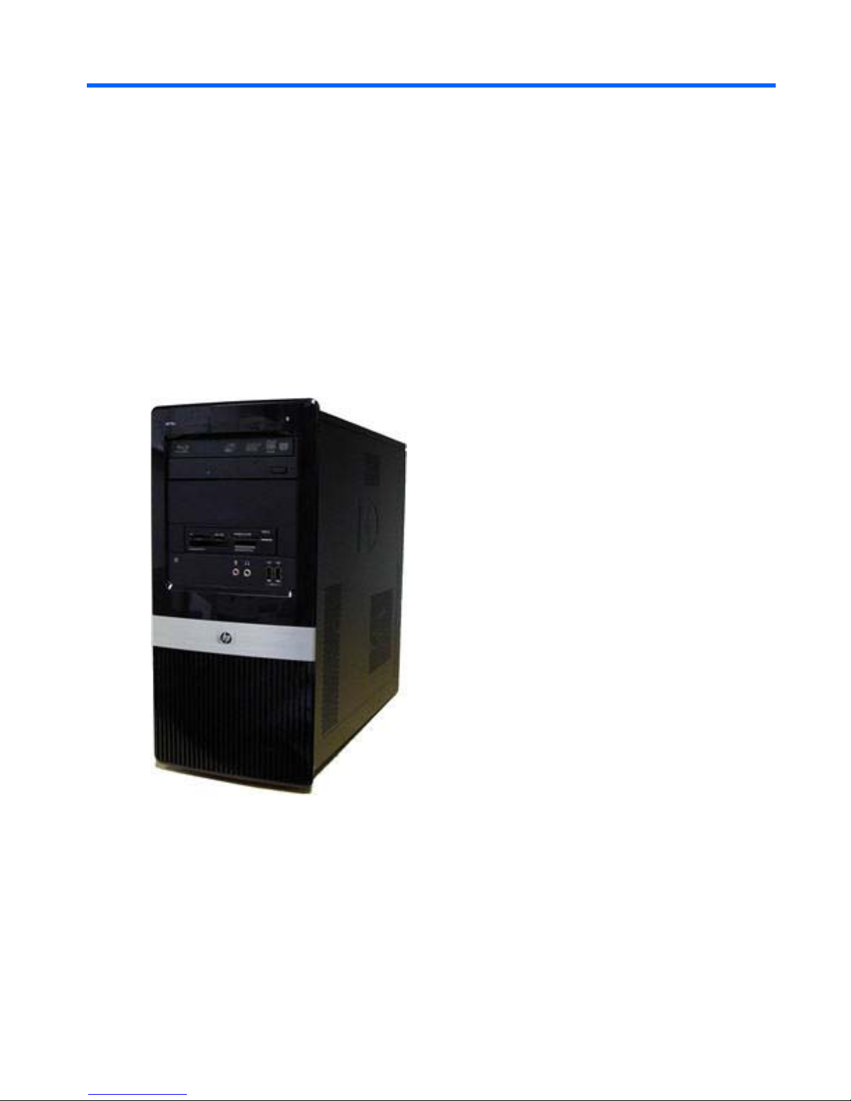
HP Pro Business PC features may vary depending on the model. For a complete listing of the
hardware and software installed in the computer, run the diagnostic utility (included on some
computer models only). Instructions for using the utility are provided in the Troubleshooting Guide.
Figure 1-1 HP Pro 2000
Standard Configuration Features 1
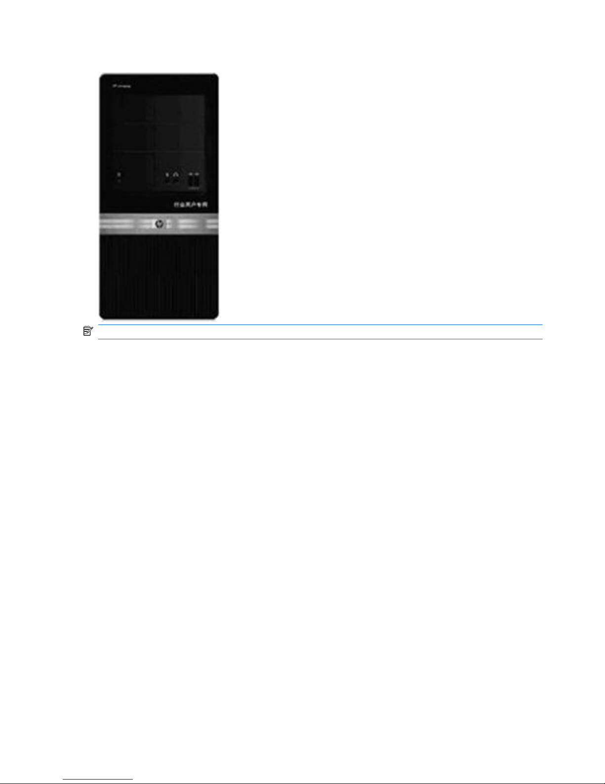
Figure 1-2 HP Pro 2080
NOTE: The drive configuration shown above may be different than your computer model.
Serviceability Features
The Microtower computer includes features that make it easy to upgrade and service. A Torx T-15 or
flat blade screwdriver is needed for many of the installation procedures described in this guide.
2 Chapter 1 Product Features
Front Panel Components
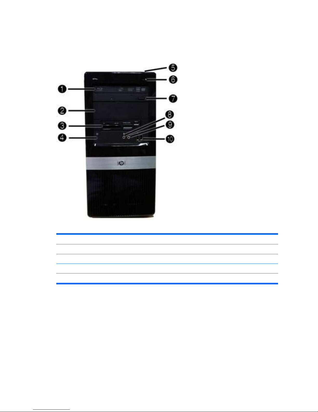
Drive configuration may vary by model.
Figure 1-3 Front Panel Components
Table 1-1 Front Panel Components
1
5.25-inch Optical Drive
1
6 Hard Drive Activity Light
2 5.25-inch Optical Drive Bay 7 Optical Drive Eject Button
3
3.5-inch Media Card Reader (optional)
2
8 Microphone Connector
4 Recovery/Reset Button 9 Headphone Connector
5 Dual-State Power Button 10 USB (Universal Serial Bus) 2.0 Ports
1
Some models have bezel blanks covering one or both of the 5.25-inch drive bays.
2
Some models have a bezel blank covering the 3.5-inch drive bay.
Front Panel Components 3
Media Card Reader Components
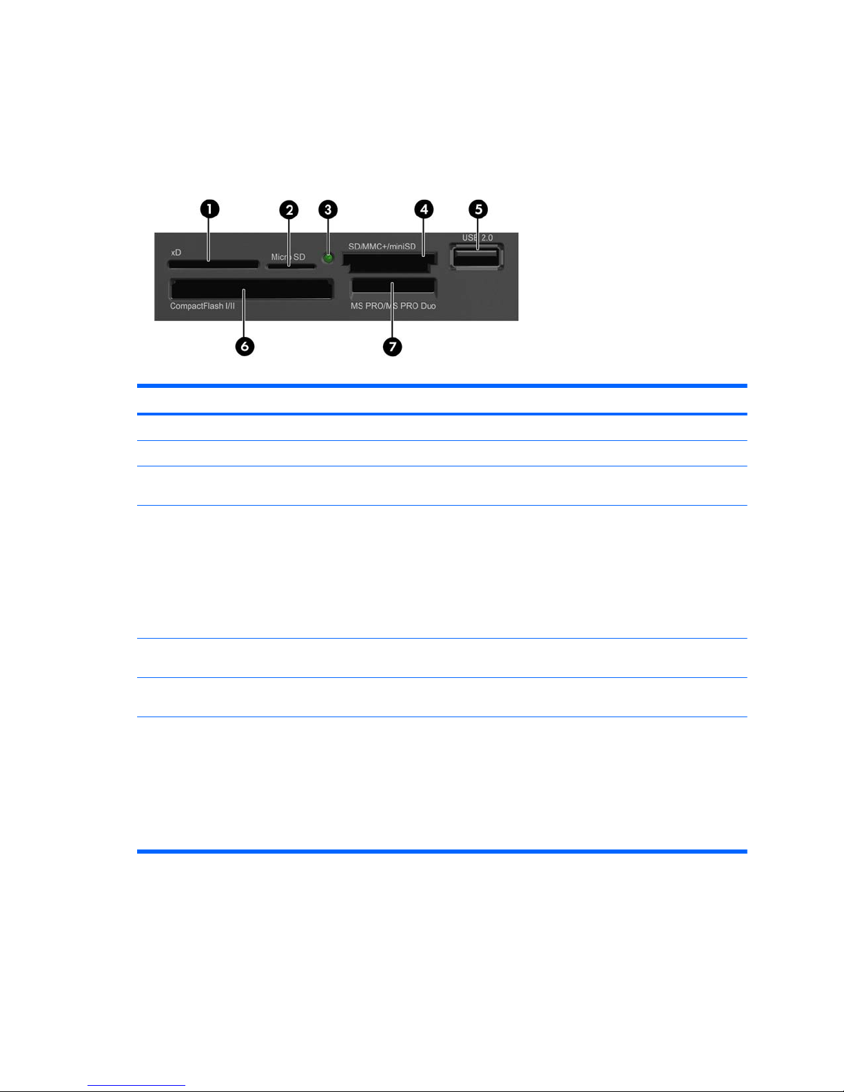
The media card reader is an optional device available on some models only. Refer to the following
illustration and table to identify the media card reader components.
Figure 1-4 Media Card Reader Components
Table 1-2 Media Card Reader Components
No. Slot Media
1 xD
●
xD-Picture Card (xD)
2 MicroSD ● MicroSD (T-Flash) ● MicroSDHC
3 Media Card Reader
Activity Light
4 SD/MMC+/miniSD ● Secure Digital (SD)
●
Secure Digital High
Capacity (SDHC)
●
MiniSD
● MiniSDHC
●
MultiMediaCard
(MMC)
●
Reduced Size
MultiMediaCard (RS
MMC)
● MultiMediaCard 4.0
(MMC Plus)
●
Reduced Size
MultiMediaCard 4.0
(MMC Mobile)
●
MMC Micro (adapter
required)
5 USB
●
USB (Universal Serial
Bus) Port
6 CompactFlash I/II
●
CompactFlash Card
Type 1
●
CompactFlash Card
Type 2
●
MicroDrive
7 MS PRO/MS PRO DUO
●
Memory Stick (MS)
● MagicGate Memory
Stick (MG)
●
MagicGate Memory
Duo
●
Memory Stick Select
● Memory Stick Duo
(MS Duo)
●
Memory Stick PRO
(MS PRO)
●
Memory Stick PRO
Duo (MS PRO Duo)
● Memory Stick PRO-
HG Duo
● Memory Stick Micro
(M2) (adapter
required)
4 Chapter 1 Product Features
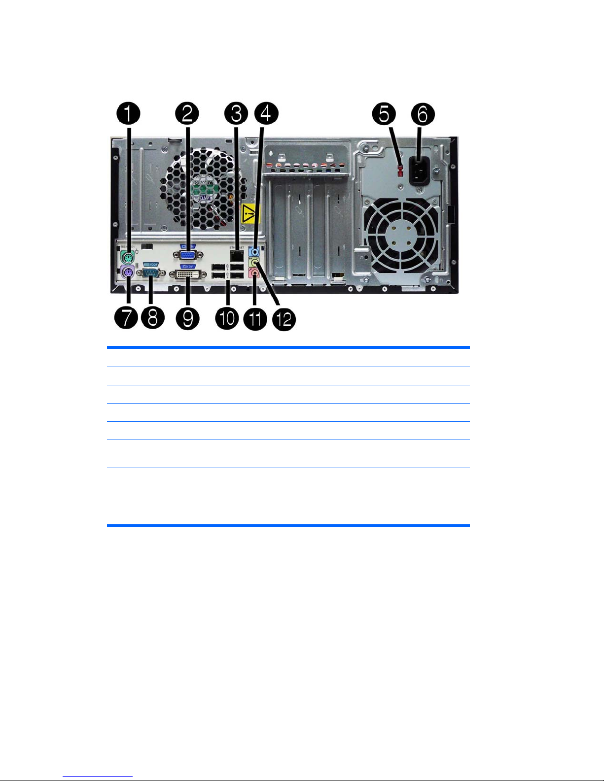
Rear Panel Components
Figure 1-5 Rear Panel Components
Table 1-3 Rear Panel Components
1 Mouse PS/2 connector 7 Keyboard PS/2 connector
2 VGA Monitor Connector 8 Serial connector
3 RJ-45 Network Connector 9 DVI Connector
4 Line-In Audio Connector (blue) 10 Universal Serial Bus (USB) Ports
5 Voltage Switch 11 Microphone Connector (pink)
6 Power Cord Connector 12 Line-Out Connector for powered audio
devices (green)
NOTE: Arrangement and number of connectors may vary by model.
When a device is plugged into the blue Line-In Audio Connector, a dialog box will pop up asking if
you want to use the connector for a line-in device or a microphone. You can reconfigure the
connector at any time by double-clicking the Realtek HD Audio Manager icon in the Windows taskbar.
Rear Panel Components 5

2 Installing and Customizing the
Software
If your computer was not shipped with a Microsoft operating system, some portions of this
documentation do not apply. Additional information is available in online help after you install the
operating system.
NOTE: If the computer was shipped with Windows Vista or Windows 7 loaded, you will be prompted
to register the computer with HP Total Care before installing the operating system. You will see a
brief movie followed by an online registration form. Fill out the form, click the Begin button, and follow
the instructions on the screen.
CAUTION: Do not add optional hardware or third-party devices to the computer until the operating
system is successfully installed. Doing so may cause errors and prevent the operating system from
installing properly.
NOTE: Be sure there is a 10.2-cm (4-inch) clearance at the back of the unit and above the monitor
to permit the required airflow.
Installing the Operating System
The first time you turn on the computer, the operating system is installed automatically. This process
takes about 5 to 10 minutes, depending on which operating system is being installed. Carefully read
and follow the instructions on the screen to complete the installation.
CAUTION: Once the automatic installation has begun, DO NOT TURN OFF THE COMPUTER
UNTIL THE PROCESS IS COMPLETE. Turning off the computer during the installation process may
damage the software that runs the computer or prevent its proper installation.
NOTE: If the computer shipped with more than one operating system language on the hard drive,
the installation process could take up to 60 minutes.
If your computer was not shipped with a Microsoft operating system, some portions of this
documentation do not apply. Additional information is available in online help after you install the
operating system.
Downloading Microsoft Windows Updates
1. To set up your Internet connection, click Start > Internet Explorer and follow the instructions on
the screen.
2. Once an Internet connection has been established, click the Start button.
3. Select the All Programs menu.
6 Chapter 2 Installing and Customizing the Software

4. Click on the Windows Update link.
In Windows Vista and Windows 7, the Windows Update screen appears. Click view available
updates and make sure all critical updates are selected. Click the Install button and follow the
instructions on the screen.
In Windows XP, you will be directed to the Microsoft Windows Update Web site. If you see
one or more pop-up windows that ask you to install a program from
http://www.microsoft.com,
click Yes to install the program. Follow the instructions on the Microsoft Web site to scan for
updates and install critical updates and service packs.
It is recommended that you install all of the critical updates and service packs.
5. After the updates have been installed, Windows will prompt you to reboot the machine. Be sure
to save any files or documents that you may have open before rebooting. Then select Yes to
reboot the machine.
Installing or Upgrading Device Drivers (Windows
systems)
When installing optional hardware devices after the operating system installation is complete, you
must also install the drivers for each of the devices.
If prompted for the i386 directory, replace the path specification with C:\i386, or use the Browse
button in the dialog box to locate the i386 folder. This action points the operating system to the
appropriate drivers.
Obtain the latest support software, including support software for the operating system from
http://www.hp.com/support. Select your country and language, select Download drivers and
software (and firmware), enter the model number of the computer, and press Enter.
Accessing Disk Image (ISO) Files
There are disk image files (ISO files) included on your PC that contain the installation software for
additional software. These CD image files are located in the folder C:\SWSetup\ISOs. Each .iso file
can be burned to CD media to create an installation CD. It is recommended that these disks be
created and the software installed in order to get the most from your PC. The software and image file
names are:
●
Corel WinDVD SD and BD – installation software for WinDVD – used to play DVD movies
●
HP Insight Diagnostics OR Vision Diagnostics – software to perform diagnostic activities on your
PC
Protecting the Software
To protect the software from loss or damage, keep a backup copy of all system software,
applications, and related files stored on the hard drive. Refer to the operating system or backup utility
documentation for instructions on making backup copies of your data files.
Installing or Upgrading Device Drivers (Windows systems) 7

3 Computer Setup (F10) Utility
Computer Setup (F10) Utilities
Use Computer Setup (F10) Utility to do the following:
●
Change factory default settings.
●
Set the system date and time.
●
Set, view, change, or verify the system configuration, including settings for processor, graphics,
memory, audio, storage, communications, and input devices.
●
Modify the boot order of bootable devices such as hard drives, diskette drives, optical drives, or
USB flash media devices.
●
Restrict a device from booting the unit.
●
Run hard drive self-tests.
●
View CPU and system temperatures.
●
Establish a supervisor password that controls access to Computer Setup (F10) Utility and the
settings described in this section.
●
Secure integrated I/O functionality, including the serial, USB, or parallel ports, audio, or
embedded NIC, so that they cannot be used until they are unsecured.
●
Enable or disable pre-boot messages.
●
Enable or disable USB legacy support.
Using Computer Setup (F10) Utilities
Computer Setup can be accessed only by turning the computer on or restarting the system.
To access the Computer Setup Utilities menu, complete the following steps:
1. Turn on or restart the computer.
2. As soon as the computer is turned on, press F10 before the system boots to the operating
system to enter Computer Setup. Press Enter to bypass the title screen, if necessary.
NOTE: If you do not press F10 at the appropriate time, you must restart the computer and
again press F10 before the unit boots to the operating system to access the utility.
3. The Computer Setup Utility screen is divided into menu headings and actions.
8 Chapter 3 Computer Setup (F10) Utility

Six menu headings appear on the Computer Setup Utility screen:
●
Main
●
Advanced
●
Boot
●
Power
●
PC Health
●
Exit
Use the arrow keys to select the appropriate heading, then press Enter. Use the arrow (up and
down) keys to select the option you want, then press Enter. To return to the previous screen,
press Esc.
4. To apply and save changes, press the F10 key.
If you have made changes that you do not want applied, press the F5 key to return to the
previous values.
To load optimized default values, press the F7 key.
CAUTION: Do NOT turn the computer power OFF while the ROM is saving the Computer Setup
(F10) changes because the CMOS could become corrupted. It is safe to turn off the computer only
after exiting the F10 Setup screen.
Table 3-1 Computer Setup (F10) Utility Main Menu
Heading Table
Main Computer Setup—Main on page 10
Advanced
Computer Setup—Advanced on page 11
Boot
Computer Setup—Boot on page 12
Power
Computer Setup—Power on page 13
PC Health
Computer Setup—PC Health on page 13
Exit
Computer Setup—Exit on page 14
Computer Setup (F10) Utilities 9

Computer Setup—Main
NOTE: Support for specific Computer Setup options may vary depending on the hardware
configuration.
Table 3-2 Computer Setup—Main
Option Description
System Information Allows you to view the following system information:
● Product Name (view only)
●
SKU Number (view only)
●
Processor Type (view only)
● Processor Speed (view only)
●
CPUID/PatchID (view only)
●
Cache Size (view only)
● Memory Size (view only)
●
Integrated MAC (view only)
●
System BIOS (view only)
● Chassis Serial Number (view only)
● Asset Tag Number (press Enter to change)
●
UUID (view only)
Set Time and Date Allows you to set system time and date.
SATA Port 1
SATA Port 2
SATA Port 3
SATA Port 4
Allows or displays the following for each SATA Port:
●
Port Configuration — Disable/enable SATA Port
●
HDD Self-Test for selected channel:
◦ SMART Status Check
◦ HDD Short Self-Test
◦
HDD Extended Self-Test
●
Vendor (view only)
● Size (view only)
●
Firmware (view only)
SATA Controller Allows you to choose how the SATA controller and devices are accessed by the operating
system. The following options are available:
● Native Mode - 4 SATA ports
●
Compatible Mode - 2 PATA devices and 2 SATA devices (ports)
Onboard FDC
Controller
Disables/enables the floppy disk controller.
Drive A (view only)
10 Chapter 3 Computer Setup (F10) Utility

Option Description
Halt On Allows you to set POST error behavior to:
●
No Errors
●
All Errors
● All But Keyboard
POST Delay Allows you to set a POST delay to:
● 0 seconds
●
5 seconds
●
10 seconds
● 15 seconds
●
30 seconds
Computer Setup—Advanced
NOTE: Support for specific Computer Setup options may vary depending on the hardware
configuration.
Table 3-3 Computer Setup—Advanced
Option Description
Execute Disable Bit Disables/enables hardware DEP function.
Intel ® Virtualization
Tech
Disables/enables Intel's Virtualization Technology feature.
Init Display First Allows you to select the primary display device:
●
OnChip VGA
●
PCI Slot
● PCIEx
MAX DVMT Allocation Allows you to specify the DVMT/system memory allocated for video memory.:
●
128MB
●
256MB
● Max
Onboard HD Audio Allows you to disable/enable onboard audio controller.
OnChip USB
Controller
Disables/enables the universal host controller interface for USB (Universal Serial Bus).
USB Legacy Support Disables/enables USB legacy support function (USB keyboard, USB mouse, and USB flash
media).
Onboard LAN Disables/enables onboard LAN controller.
Table 3-2 Computer Setup—Main (continued)
Computer Setup (F10) Utilities 11

Option Description
Onboard LAN Boot
ROM
Disables/enables the boot ROM of the onboard LAN chip.
Onboard Serial Port 1 Allows you to select a setting for the onboard serial port:
●
Disabled
●
3F8/IRQ4
● 2F8/IRQ3
● 3E8/IRQ4
●
2E8/IRQ3
Computer Setup—Boot
NOTE: Support for specific Computer Setup options may vary depending on the hardware
configuration.
Table 3-4 Computer Setup—Boot
Option Description
F9 Boot Menu Disables/enables F9 Boot Menu.
F10 Setup Prompt Disables/enables the F10 Setup prompt message on the logo screen.
F11 Recovery Disables/enables F11 Recovery and provides the option of showing the F11 Recovery prompt
message on the logo screen. Choose from the following:
● Disabled
●
Enabled no prompt
●
Enabled and prompt
F12 Boot from LAN
Prompt
Disables/enables the F12 Boot from LAN prompt message on the logo screen.
Hard Disk Boot Seq. Allows you to specify the order of attached hard drive devices (such as USB HDD storage or USB
flash media). The first drive in the order has priority in the boot sequence and is recognized as
drive C (if any devices are attached).
Optical Drive Boot
Seq.
Allows you to specify the order in which attached optical drives (including USB ODD) are checked
for a bootable operating system image.
Network Boot Seq. Allows you to specify the order in which network devices (including UP NIC cards) are checked for
a bootable operating system image.
First Boot Device
Second Boot Device
Third Boot Device
Fourth Boot Device
Allows you to specify which devices will boot first, second, third, and fourth or to disable any of the
four:
● Removable
●
CDROM
●
Hard Disk
● Network
NOTE: MS-DOS drive lettering assignments may not apply after a non-MS-DOS operating
system has started.
Table 3-3 Computer Setup—Advanced (continued)
12 Chapter 3 Computer Setup (F10) Utility

Option Description
Set Supervisor
Password
Allows you to establish a password to control access to Computer Setup.
BIOS Write Protection Disables/enables BIOS upgrading.
Computer Setup—Power
NOTE: Support for specific Computer Setup options may vary depending on the hardware
configuration.
Table 3-5 Computer Setup—Power
Option Description
After AC Power Loss Allows you to select system power loss behavior:
●
Off
●
On
● Last State
Wake on PCI Device
from S5
Disables/enables waking up from S5 by PCI device.
RTC Alarm Resume Disables/enables RTC (real-time clock) alarm.
Computer Setup—PC Health
NOTE: Support for specific Computer Setup options may vary depending on the hardware
configuration.
Table 3-6 Computer Setup—PC Health
Option Description
Chassis Opened
Warning
Allows you to disable/enable the chassis intrusion function and clear the intrusion warning.
●
Disabled
●
Enabled
● Clear
System Fan Fail
Check
Disables/enables detection of system fan during POST.
Smart Fan Function Disables/enables Smart Fan functionality. Enabling optimizes fan control for best acoustic
behavior.
Current CPU
Temperature
(view only)
Current System
Temperature
(view only)
Table 3-4 Computer Setup—Boot (continued)
Computer Setup (F10) Utilities 13

Option Description
Current CPU Fan
Speed
(view only)
Current System Fan
Speed
(view only)
Computer Setup—Exit
Table 3-7 Computer Setup—Exit
Option Description
Save Changes and Exit Allows you to save current settings and exit Computer Setup.
Discard Changes and
Exit
Allows you to exit Computer Setup without saving changes.
Load Optimal Defaults Allows you to reset Computer Setup to factory defaults.
Table 3-6 Computer Setup—PC Health (continued)
14 Chapter 3 Computer Setup (F10) Utility

4 Serial ATA (SATA) Drive Guidelines
and Features
NOTE: HP only supports the use of SATA hard drives on these models of computer. No Parallel
ATA (PATA) drives are supported.
SATA Hard Drives
Serial ATA Hard Drive Characteristics
Number of pins/conductors in data cable 7/7
Number of pins in power cable 15
Maximum data cable length 39.37 in (100 cm)
Data interface voltage differential 400-700 mV
Drive voltages 3.3 V, 5 V, 12 V
Jumpers for configuring drive N/A
Data transfer rate 3.0 Gb/s
SATA Hard Drive Cables
SATA Data Cable
Always use an HP approved SATA 3.0 Gb/s cable as it is fully backwards compatible with the SATA
1.5 Gb/s drives.
Current HP desktop products ship with SATA 3.0 Gb/s hard drives.
SATA data cables are susceptible to damage if overflexed. Never crease a SATA data cable and
never bend it tighter than a 30 mm (1.18 in) radius.
The SATA data cable is a thin, 7-pin cable designed to transmit data for only a single drive.
SATA Hard Drives 15

SMART ATA Drives
The Self Monitoring Analysis and Recording Technology (SMART) ATA drives for the HP Personal
Computers have built-in drive failure prediction that warns the user or network administrator of an
impending failure or crash of the hard drive. The SMART drive tracks fault prediction and failure
indication parameters such as reallocated sector count, spin retry count, and calibration retry count. If
the drive determines that a failure is imminent, it generates a fault alert.
Hard Drive Capacities
The combination of the file system and the operating system used in the computer determines the
maximum usable size of a drive partition. A drive partition is the largest segment of a drive that may
be properly accessed by the operating system. A single hard drive may therefore be subdivided into a
number of unique drive partitions in order to make use of all of its space.
Because of the differences in the way that drive sizes are calculated, the size reported by the
operating system may differ from that marked on the hard drive or listed in the computer specification.
Drive size calculations by drive manufacturers are bytes to the base 10 while calculations by
Microsoft are bytes to the base 2.
Drive/Partition Capacity Limits
Maximum Size
File System Controller Type Operating System Partition Drive
FAT 32 ATA Windows XP/Windows Vista/Windows 7 32 GB 2 TB
NTFS ATA Windows XP/Windows Vista/Windows 7 2 TB 2 TB
16 Chapter 4 Serial ATA (SATA) Drive Guidelines and Features

5 Identifying the Chassis, Routine Care,
and Disassembly Preparation
This chapter provides general service information for the computer. Adherence to the procedures and
precautions described in this chapter is essential for proper service.
CAUTION: When the computer is plugged into an AC power source, voltage is always applied to
the system board. You must disconnect the power cord from the power source before opening the
computer to prevent system board or component damage.
Electrostatic Discharge Information
A sudden discharge of static electricity from your finger or other conductor can destroy static-sensitive
devices or microcircuitry. Often the spark is neither felt nor heard, but damage occurs. An electronic
device exposed to electrostatic discharge (ESD) may not appear to be affected at all and can work
perfectly throughout a normal cycle. The device may function normally for a while, but it has been
degraded in the internal layers, reducing its life expectancy.
Networks built into many integrated circuits provide some protection, but in many cases, the
discharge contains enough power to alter device parameters or melt silicon junctions.
Generating Static
The following table shows that:
●
Different activities generate different amounts of static electricity.
●
Static electricity increases as humidity decreases.
Relative Humidity
Event 55% 40% 10%
Walking across carpet
Walking across vinyl floor
Motions of bench worker
Removing DIPs* from plastic tube
7,500 V
3,000 V
400 V
400 V
15,000 V
5,000 V
800 V
700 V
35,000 V
12,000 V
6,000 V
2,000 V
Electrostatic Discharge Information 17

Removing DIPs* from vinyl tray
Removing DIPs* from Styrofoam
Removing bubble pack from PCB
Packing PCBs in foam-lined box
2,000 V
3,500 V
7,000 V
5,000 V
4,000 V
5,000 V
20,000 V
11,000 V
11,500 V
14,500 V
26,500 V
21,000 V
*These are then multi-packaged inside plastic tubes, trays, or Styrofoam.
NOTE: 700 volts can degrade a product.
Preventing Electrostatic Damage to Equipment
Many electronic components are sensitive to ESD. Circuitry design and structure determine the
degree of sensitivity. The following packaging and grounding precautions are necessary to prevent
damage to electric components and accessories.
●
To avoid hand contact, transport products in static-safe containers such as tubes, bags, or
boxes.
●
Protect all electrostatic parts and assemblies with conductive or approved containers or
packaging.
●
Keep electrostatic sensitive parts in their containers until they arrive at static-free stations.
●
Place items on a grounded surface before removing them from their container.
●
Always be properly grounded when touching a sensitive component or assembly.
●
Avoid contact with pins, leads, or circuitry.
●
Place reusable electrostatic-sensitive parts from assemblies in protective packaging or
conductive foam.
Personal Grounding Methods and Equipment
Use the following equipment to prevent static electricity damage to equipment:
●
Wrist straps are flexible straps with a maximum of one-megohm ± 10% resistance in the ground
cords. To provide proper ground, a strap must be worn snug against bare skin. The ground cord
must be connected and fit snugly into the banana plug connector on the grounding mat or
workstation.
●
Heel straps/Toe straps/Boot straps can be used at standing workstations and are compatible
with most types of shoes or boots. On conductive floors or dissipative floor mats, use them on
both feet with a maximum of one-megohm ± 10% resistance between the operator and ground.
Static Shielding Protection Levels
Method Voltage
Antistatic plastic
Carbon-loaded plastic
Metallized laminate
1,500
7,500
15,000
18 Chapter 5 Identifying the Chassis, Routine Care, and Disassembly Preparation

Grounding the Work Area
To prevent static damage at the work area, use the following precautions:
● Cover the work surface with approved static-dissipative material. Provide a wrist strap connected
to the work surface and properly grounded tools and equipment.
● Use static-dissipative mats, foot straps, or air ionizers to give added protection.
● Handle electrostatic sensitive components, parts, and assemblies by the case or PCB laminate.
Handle them only at static-free work areas.
● Turn off power and input signals before inserting and removing connectors or test equipment.
● Use fixtures made of static-safe materials when fixtures must directly contact dissipative
surfaces.
● Keep work area free of nonconductive materials such as ordinary plastic assembly aids and
Styrofoam.
●
Use field service tools, such as cutters, screwdrivers, and vacuums, that are conductive.
Recommended Materials and Equipment
Materials and equipment that are recommended for use in preventing static electricity include:
●
Antistatic tape
●
Antistatic smocks, aprons, or sleeve protectors
●
Conductive bins and other assembly or soldering aids
●
Conductive foam
●
Conductive tabletop workstations with ground cord of one-megohm +/- 10% resistance
●
Static-dissipative table or floor mats with hard tie to ground
●
Field service kits
●
Static awareness labels
●
Wrist straps and footwear straps providing one-megohm +/- 10% resistance
●
Material handling packages
●
Conductive plastic bags
●
Conductive plastic tubes
●
Conductive tote boxes
●
Opaque shielding bags
●
Transparent metallized shielding bags
●
Transparent shielding tubes
Electrostatic Discharge Information 19

Operating Guidelines
To prevent overheating and to help prolong the life of the computer:
●
Keep the computer away from excessive moisture, direct sunlight, and extremes of heat and
cold.
●
Operate the computer on a sturdy, level surface. Leave a 10.2-cm (4-inch) clearance on all
vented sides of the computer and above the monitor to permit the required airflow.
●
Never restrict the airflow into the computer by blocking any vents or air intakes. Do not place the
keyboard, with the keyboard feet down, directly against the front of the desktop unit as this also
restricts airflow.
●
Occasionally clean the air vents on all vented sides of the computer. Lint, dust, and other foreign
matter can block the vents and limit the airflow. Be sure to unplug the computer before cleaning
the air vents.
●
Never operate the computer with the cover or side panel removed.
●
Do not stack computers on top of each other or place computers so near each other that they
are subject to each other’s re-circulated or preheated air.
●
If the computer is to be operated within a separate enclosure, intake and exhaust ventilation
must be provided on the enclosure, and the same operating guidelines listed above will still
apply.
●
Keep liquids away from the computer and keyboard.
●
Never cover the ventilation slots on the monitor with any type of material.
●
Install or enable power management functions of the operating system or other software,
including sleep states.
20 Chapter 5 Identifying the Chassis, Routine Care, and Disassembly Preparation

Routine Care
General Cleaning Safety Precautions
1. Never use solvents or flammable solutions to clean the computer.
2. Never immerse any parts in water or cleaning solutions; apply any liquids to a clean cloth and
then use the cloth on the component.
3. Always unplug the computer when cleaning with liquids or damp cloths.
4. Always unplug the computer before cleaning the keyboard, mouse, or air vents.
5. Disconnect the keyboard before cleaning it.
6. Wear safety glasses equipped with side shields when cleaning the keyboard.
Cleaning the Computer Case
Follow all safety precautions in General Cleaning Safety Precautions on page 21 before cleaning the
computer.
To clean the computer case, follow the procedures described below:
●
To remove light stains or dirt, use plain water with a clean, lint-free cloth or swab.
●
For stronger stains, use a mild dishwashing liquid diluted with water. Rinse well by wiping it with
a cloth or swab dampened with clear water.
●
For stubborn stains, use isopropyl (rubbing) alcohol. No rinsing is needed as the alcohol will
evaporate quickly and not leave a residue.
●
After cleaning, always wipe the unit with a clean, lint-free cloth.
●
Occasionally clean the air vents on the computer. Lint and other foreign matter can block the
vents and limit the airflow.
Cleaning the Keyboard
Follow all safety precautions in General Cleaning Safety Precautions on page 21 before cleaning the
keyboard.
To clean the tops of the keys or the keyboard body, follow the procedures described in
Cleaning the
Computer Case on page 21.
When cleaning debris from under the keys, review all rules in
General Cleaning Safety Precautions
on page 21 before following these procedures:
CAUTION: Use safety glasses equipped with side shields before attempting to clean debris from
under the keys.
●
Visible debris underneath or between the keys may be removed by vacuuming or shaking.
●
Canned, pressurized air may be used to clean debris from under the keys. Caution should be
used as too much air pressure can dislodge lubricants applied under the wide keys.
Routine Care 21

●
If you remove a key, use a specially designed key puller to prevent damage to the keys. This
tool is available through many electronic supply outlets.
CAUTION: Never remove a wide leveled key (like the space bar) from the keyboard. If these
keys are improperly removed or installed, the keyboard may not function properly.
●
Cleaning under a key may be done with a swab moistened with isopropyl alcohol and squeezed
out. Be careful not to wipe away lubricants necessary for proper key functions. Use tweezers to
remove any fibers or dirt in confined areas. Allow the parts to air dry before reassembly.
Cleaning the Monitor
●
Wipe the monitor screen with a clean cloth moistened with water or with a towelette designed for
cleaning monitors. Do not use sprays or aerosols directly on the screen; the liquid may seep into
the housing and damage a component. Never use solvents or flammable liquids on the monitor.
●
To clean the monitor body follow the procedures in
Cleaning the Computer Case on page 21.
Cleaning the Mouse
Before cleaning the mouse, ensure that the power to the computer is turned off.
●
Clean the mouse ball by first removing the retaining plate and the ball from the housing. Pull out
any debris from the ball socket and wipe the ball with a clean, dry cloth before reassembly.
●
To clean the mouse body, follow the procedures in
Cleaning the Computer Case on page 21.
Service Considerations
Listed below are some of the considerations that you should keep in mind during the disassembly and
assembly of the computer.
Power Supply Fan
The power supply fan is a variable-speed fan based on the temperature in the power supply.
CAUTION: The cooling fan is always on when the computer is in the “On” mode. The cooling fan is
off when the computer is in “Standby,” “Suspend,” or “Off” modes.
You must disconnect the power cord from the power source before opening the computer to prevent
system board or component damage.
Tools and Software Requirements
To service the computer, you need the following:
●
Torx T-15 screwdriver (HP screwdriver with bits, PN 161946-001)
● Torx T-15 screwdriver with small diameter shank (for certain front bezel removal)
● Flat-bladed screwdriver (may sometimes be used in place of the Torx screwdriver)
●
Phillips #2 screwdriver
22 Chapter 5 Identifying the Chassis, Routine Care, and Disassembly Preparation
 Loading...