

Page 1
Part I
Click here to access Part II
on hp.com.
Page 2

Page 3

PCL 5 Printer LanguageTechnical
Reference Manual
HP Part No. 5961-0509
Printed in USA
First Edition - October 1992
Page 4

Notice
This document contains proprietary information which is protected by
copyright. All rights are reserved. No part of this document may be
photocopied, reproduced, or translated to another language without
the prior written consent of Hewlett-Packard Company. The
information contained in this document is subject to change without
notice.
ii EN
Page 5
Printing History
This manual was created using HP Tag/Vectra software on an
HP Vectra Personal Computer. The body text is printed in Helvetica
fonts. The camera-ready copy was printed on an HP LaserJet IIISi
printer with Resolution Enhancement technology (REt) and was then
reproduced using standard offset printing.
First Edition – October 1992
NOTICE
This document is the current edition of the technical reference manual for PCL
5 and earlier printers. It replaces the September 1990 edition of the HP PCL 5
Printer Language Technical Reference Manual (p/n 33459-90903). If you have
ordered another PCL Technical Reference document, this manual and the PCL
5 Comparison Guide are the updated replacement documents.
EN iii
Page 6

Trademark Credits
Intellifont and Garth Graphic are U.S. registered trademarks of Agfa
Division, Miles Inc. CG Triumvirate and Shannon are trademarks of
Agfa Division, Miles Inc. CG Bodoni, CG Century Schoolbook, CG
Goudy Old Style, CG Melliza, Microstyle, CG Omega, CG Palacio,
CG Times and CG Trump Mediaeval are products of Agfa Division,
Miles Inc. CG Times, a product of Agfa Division, Miles Inc., is based
on Times New Roman, a U.S. registered trademark of Monotype
Corporation plc. PCL, and Vectra are U.S. registered trademarks of
Hewlett-Packard Company. Resolution Enhancement is a trademark
of Hewlett-Packard Company. IBM is a registered trademark of
International Business Machines Corporation. Microsoft, Windows,
and MS-DOS are U.S. registered trademarks of Microsoft
Corporation. TrueType and Macintosh are registered trademarks of
Apple Computer, Inc. PostScript is a registered trademark of Adobe
Systems, Inc. Centronics is a U.S. registered trademark of Centronics
Corporation. ITC Avant Garde Gothic, ITC Benguiat, ITC Bookman,
ITC Cheltenham, ITC Galliard, ITC Korinna, ITC Lubalin Graph, ITC
Souvenir, ITC Zapf Chancery and ITC Zapf Dingbats are U.S.
registered trademarks of International Typeface Corporation. ITC
Tiffany is a trademark of International Typeface Corporation. Futura is
a U.S. registered trademark of Fundicion Tipografica Neufville, S.A.
Serifa is a trademark of Fundicion Tipografica Neufville, S.A. Letraset
is a registered trademark of Esselte Pendaflex Corporation. Revue
and University Roman are trademarks of Esselte Pendaflex
Corporation. Helvetica and Times Roman are trademarks of Linotype
AG and its subsidiaries. Univers is a U.S. registered trademark of
Linotype AG and its subsidiaries. Antique Olive is a trademark of
Monsieur Marcel OLIVE. Arial and Gill Sans are registered
trademarks of The Monotype Corporation plc.
iv EN
Page 7

Inside This Manual
What You Can Learn From This Manual
Hewlett-Packard has developed a standard set of printer features for
use in all HP printers. Printer features are accessed through the
corresponding commands of Hewlett-Packard’s PCL language. This
manual describes the PCL 5 printer language. This includes
descriptions of the commands available for Hewlett-Packard PCL 5
LaserJet printers and the basic requirements of PCL language
programming. With the release of new LaserJet family printers there
are new features added which supplement the existing PCL base set.
Features of future printer releases are not covered in this document.
The new features are described in the latest version of the P CL 5
Comparison Guide. Programmers should familiarize themselves with
the information provided in the PCL 5 Comparison Guide in addition
to the information in this document.
Experienced Users
This manual was written for people with some programming
experience. Many of the concept discussions assume some
programming knowledge.
When writing a PCL language program, you should know the PCL
language concepts and commands presented in this manual, and
should be aware of the differences in implementation of the PCL 5
printer language for the various HP LaserJet printers, as described in
the PCL 5 Comparison Guide.
Non-technical Users
Many software applications (word processing software, spreadsheets,
etc.) allow you to embed printer commands as escape sequences in
the body of your documents. This manual presents the full syntax and
explanation of all the commands supported by PCL 5 LaserJet
printers. These commands enable you to take advantage of the
LaserJet printer’s advanced feature set.
EN v
Page 8

Note Since actual implementation of printer commands within software
applications varies from package to package, specific examples are
not given. For examples of printer command usage with many popular
software packages, refer to HP’s Software Application Notes,
provided with the printer. The most current versions of software
application notes can be obtained through the HP Forum on
CompuServe, by fax using the HP FIRST fax service, or through
HP’s literature distribution. Refer to Appendix A for more information.
Chapter Summaries
A brief description of each chapter is provided below.
Chapter 1 - Introduction to HP PCL
This chapter gives a brief history of the development of the PCL
language, describes the PCL language levels (architecture), and
describes the PCL command structure (control codes and escape
sequences).
Chapter 2 - The Page
This chapter introduces the idea of the logical page and identifies the
area in which printing can occur. It also describes the PCL coordinate
system and the HP-GL/2 picture frame.
Chapter 3 - The Print Environment
This chapter introduces the printer’s feature settings, collectively, as
the print environment. It includes descriptions of the factory default
environment, user default environment, and the modified print
environment. The effect of printer reset functions is also described.
Chapter 4 - PCL Job Control Commands
This chapter describes the commands which provide job control.
Job control commands are usually grouped together and sent at the
beginning of a job. Job control includes restoration of the User Default
Environment, selection of the number of copies of each page to be
printed, duplex print commands, and unit of measure specification.
vi EN
Page 9

Chapter 5 - Page Control Commands
This chapter describes the commands providing page format control.
Page format control allows you to select the page source, size,
orientation, margins, and text spacing.
Chapter 6 - Cursor Positioning
This chapter describes how to position the cursor within the logical
page.
Chapter 7 - Fonts
This chapter describes basic font information including font
characteristics.
Chapter 8 - PCL Font Selection
This chapter describes how to select a font for printing using the font
characteristics commands. The underline feature is described at the
end of the chapter.
Chapter 9 - Font Management
This chapter describes font management which provides
mechanisms for downloading and manipulating soft fonts.
Chapter 10 - User-Defined Symbol Sets
This chapter describes the capability of some PCL 5 printers to
enable users to define their own symbol sets for special needs.
Chapter 11 - Soft Font Creation
This chapter describes how to organize font/character data for
downloading to the printer.
Chapter 12 - Macros
This chapter describes macro commands which store a block of PCL
commands and data which can be used repeatedly without redefining
the block. The macro function reduces the number of commands that
must be sent to the printer.
EN vii
Page 10

Chapter 13 - The PCL Print Model
This chapter describes the PCL print model which allows for special
effects when printing.
Chapter 14 - PCL Rectangular Area Fill Graphics
This chapter describes how to define and fill a rectangular area with
one of the predefined PCL patterns, or with a user-defined pattern.
Chapter 15 - Raster Graphics
This chapter describes how to download raster graphics to the printer,
and includes various techniques for reducing the amount of data
needed to define the raster image.
Chapter 16 - Status Readback
This chapter describes the PCL status readback features. Status
readback enables you to obtain PCL status information from the
printer, such as: available printer (user) memory, a list of fonts and
symbol sets, and the ID numbers of macros and user-defined
patterns.
Chapter 17 - An Introduction to HP-GL/2 Vector
Graphics
This chapter introduces basic information for HP-GL/2. It lists the
vector graphics commands, and describes the HP-GL/2 command
syntax. An overview of several important topics is also provided, such
as the PCL Picture Frame concept, scaling, pen status and location,
and absolute vs. relative pen movement.
Chapter 18 - The Picture Frame
This chapter describes how to set up an area on the page for printing
vector graphics (the PCL Picture Frame). It discuses the commands
necessary to define and position the picture frame, along with the
commands used to enter and exit HP-GL/2 mode.
viii EN
Page 11

Chapter 19 - The Configuration and Status Group
This chapter describes the commands used to set default conditions
and values for programmable HP-GL/2 features. It also explains the
commands used for scaling, establishing a soft-clip window, and
rotating the HP-GL/2 coordinate system.
Chapter 20 - The Vector Group
This chapter provides information about pen movement and drawing
lines, arcs, and circles. It also covers a way to encode coordinates for
increased print speed.
Chapter 21 - The Polygon Group
This chapter explains the polygon mode and how it is used to draw
polygons, subpolygons and circles. The commands for drawing and
filling wedges and rectangles are also described in this chapter.
Chapter 22 - The Line and Fill Attributes Group
This chapter describes the commands used to vary the line types and
fill patterns used to create HP-GL/2 graphics.
Chapter 23 - The Character Group
This chapter contains information about the commands used to print
text (labels) in HP-GL/2 mode. This allows you to print HP-GL/2 labels
in almost any size, slant and direction using proportional or
fixed-spaced scalable fonts.
Chapter 24 - Programming Hints
This chapter provides programming information for use during the
development of PCL software.
EN ix
Page 12

Related Documentation
The following related manuals provide further information about
HP LaserJet printers, including their features and functions.
PCL 5 Comparison Guide
This document contains supplemental information for programming
PCL 5 LaserJet printers. It identifies how different HP PCL 5 LaserJet
printers implement the commands described in the HP PCL 5 Printer
Language Technical Reference Manual. It provides printer-specific
information on feature sets, paper handling, fonts, and the printer’s
control panel.
Intellifont Scalable Typeface Format
This document provides information for designing scalable fonts using
Agfa’s Font Access Interchange Standard (FAIS). This document can
be obtained from Agfa Division, Miles Inc. by writing to the address
below or by phone.
Agfa Division, Miles Inc.
Typographic Systems
OEM Technical Support
90 Industrial Way
Wilmington, MA 01887
(508) 658-5600
TrueType Font Files
This document, which provides information for designing scalable
fonts using Microsoft Corporation’s TrueType font scaling technology
has been made available in downloadable form on both CompuServe
and Internet. Contact Microsoft Corporation for details.
x EN
Page 13

Contents
Notice . . . . . . . . . . . . . . . . . . . . . . . . . . . . . . . . . . . . . . . . . . . . . . . . . . . . . . . . . . . . . ii
Printing History . . . . . . . . . . . . . . . . . . . . . . . . . . . . . . . . . . . . . . . . . . . . . . . . . . . . . . iii
Trademark Credits . . . . . . . . . . . . . . . . . . . . . . . . . . . . . . . . . . . . . . . . . . . . . . . . . . . . iv
Inside This Manual . . . . . . . . . . . . . . . . . . . . . . . . . . . . . . . . . . . . . . . . . . . . . . . . . . . v
What You Can Learn From This Manual. . . . . . . . . . . . . . . . . . . . . . . . . . . . . . . . v
Related Documentation. . . . . . . . . . . . . . . . . . . . . . . . . . . . . . . . . . . . . . . . . . . . . . . . x
PCL 5 Comparison Guide. . . . . . . . . . . . . . . . . . . . . . . . . . . . . . . . . . . . . . . . . . . x
Intellifont Scalable Typeface Format. . . . . . . . . . . . . . . . . . . . . . . . . . . . . . . . . . . x
TrueType Font Files. . . . . . . . . . . . . . . . . . . . . . . . . . . . . . . . . . . . . . . . . . . . . . . . x
Introduction to HP PCL
PCL Printer Language Architecture . . . . . . . . . . . . . . . . . . . . . . . . . . . . . . . . . . . . .1-2
What are Printer Commands?. . . . . . . . . . . . . . . . . . . . . . . . . . . . . . . . . . . . . . . . . .1-3
Control Codes. . . . . . . . . . . . . . . . . . . . . . . . . . . . . . . . . . . . . . . . . . . . . . . . . . .1-3
PCL Commands . . . . . . . . . . . . . . . . . . . . . . . . . . . . . . . . . . . . . . . . . . . . . . . . .1-3
HP-GL/2 Commands . . . . . . . . . . . . . . . . . . . . . . . . . . . . . . . . . . . . . . . . . . . . .1-4
PJL Commands . . . . . . . . . . . . . . . . . . . . . . . . . . . . . . . . . . . . . . . . . . . . . . . . .1-4
Syntax of Escape Sequences . . . . . . . . . . . . . . . . . . . . . . . . . . . . . . . . . . . . . . . . . .1-5
Two-Character Escape Sequences. . . . . . . . . . . . . . . . . . . . . . . . . . . . . . . . . . .1-5
Parameterized Escape Sequences. . . . . . . . . . . . . . . . . . . . . . . . . . . . . . . . . . .1-6
The Page
Logical Page . . . . . . . . . . . . . . . . . . . . . . . . . . . . . . . . . . . . . . . . . . . . . . . . . . . . . . .2-2
Printed Dots . . . . . . . . . . . . . . . . . . . . . . . . . . . . . . . . . . . . . . . . . . . . . . . . . . . . . . .2-3
PCL Coordinate System . . . . . . . . . . . . . . . . . . . . . . . . . . . . . . . . . . . . . . . . . . . . . .2-4
Units of the PCL Coordinate System. . . . . . . . . . . . . . . . . . . . . . . . . . . . . . . . . . . . .2-5
PCL Units . . . . . . . . . . . . . . . . . . . . . . . . . . . . . . . . . . . . . . . . . . . . . . . . . . . . . .2-5
Decipoints . . . . . . . . . . . . . . . . . . . . . . . . . . . . . . . . . . . . . . . . . . . . . . . . . . . . . .2-5
Columns & Rows . . . . . . . . . . . . . . . . . . . . . . . . . . . . . . . . . . . . . . . . . . . . . . . .2-5
Printer Internal Units . . . . . . . . . . . . . . . . . . . . . . . . . . . . . . . . . . . . . . . . . . . . . .2-5
HP-GL/2 Picture Frame. . . . . . . . . . . . . . . . . . . . . . . . . . . . . . . . . . . . . . . . . . . . . . .2-6
Printable Area . . . . . . . . . . . . . . . . . . . . . . . . . . . . . . . . . . . . . . . . . . . . . . . . . . . . . .2-7
EN Contents-1
Page 14

The Print Environment
Factory Default Environment. . . . . . . . . . . . . . . . . . . . . . . . . . . . . . . . . . . . . . . . . . .3-2
User Default Environment . . . . . . . . . . . . . . . . . . . . . . . . . . . . . . . . . . . . . . . . . . . . .3-6
Modified Print Environment . . . . . . . . . . . . . . . . . . . . . . . . . . . . . . . . . . . . . . . . . . . .3-7
Resetting the Print Environment . . . . . . . . . . . . . . . . . . . . . . . . . . . . . . . . . . . . . . . .3-8
Printer Reset. . . . . . . . . . . . . . . . . . . . . . . . . . . . . . . . . . . . . . . . . . . . . . . . . . . .3-8
Cold Reset . . . . . . . . . . . . . . . . . . . . . . . . . . . . . . . . . . . . . . . . . . . . . . . . . . . . .3-9
PCL Job Control Commands
Printer Reset Command . . . . . . . . . . . . . . . . . . . . . . . . . . . . . . . . . . . . . . . . . . . . . .4-2
Universal Exit Language Command . . . . . . . . . . . . . . . . . . . . . . . . . . . . . . . . . . . . .4-3
Number of Copies Command . . . . . . . . . . . . . . . . . . . . . . . . . . . . . . . . . . . . . . . . . .4-4
Simplex/Duplex Print Command . . . . . . . . . . . . . . . . . . . . . . . . . . . . . . . . . . . . . . . .4-5
Left Offset Registration Command . . . . . . . . . . . . . . . . . . . . . . . . . . . . . . . . . . . . . .4-7
Top Offset Registration Command . . . . . . . . . . . . . . . . . . . . . . . . . . . . . . . . . . . . . .4-8
Duplex Page Side Selection Command . . . . . . . . . . . . . . . . . . . . . . . . . . . . . . . . .4-10
Job Separation Command. . . . . . . . . . . . . . . . . . . . . . . . . . . . . . . . . . . . . . . . . . . .4-11
Output Bin Selection Command . . . . . . . . . . . . . . . . . . . . . . . . . . . . . . . . . . . . . . .4-12
Unit of Measure Command . . . . . . . . . . . . . . . . . . . . . . . . . . . . . . . . . . . . . . . . . . .4-13
Page Control Commands
Page Size Command. . . . . . . . . . . . . . . . . . . . . . . . . . . . . . . . . . . . . . . . . . . . . . . . .5-2
PAPER SOURCE COMMAND . . . . . . . . . . . . . . . . . . . . . . . . . . . . . . . . . . . . . . . . .5-4
Logical Page Orientation Command . . . . . . . . . . . . . . . . . . . . . . . . . . . . . . . . . . . . .5-5
Print Direction Command . . . . . . . . . . . . . . . . . . . . . . . . . . . . . . . . . . . . . . . . . . . . .5-9
Text Area . . . . . . . . . . . . . . . . . . . . . . . . . . . . . . . . . . . . . . . . . . . . . . . . . . . . . . . . .5-11
Left Margin Command. . . . . . . . . . . . . . . . . . . . . . . . . . . . . . . . . . . . . . . . . . . . . . .5-13
Right Margin Command . . . . . . . . . . . . . . . . . . . . . . . . . . . . . . . . . . . . . . . . . . . . .5-14
Clear Horizontal Margins Command . . . . . . . . . . . . . . . . . . . . . . . . . . . . . . . . . . . .5-15
Top Margin Command . . . . . . . . . . . . . . . . . . . . . . . . . . . . . . . . . . . . . . . . . . . . . . .5-16
Text Length Command . . . . . . . . . . . . . . . . . . . . . . . . . . . . . . . . . . . . . . . . . . . . . .5-18
Perforation Skip Command . . . . . . . . . . . . . . . . . . . . . . . . . . . . . . . . . . . . . . . . . . .5-19
Horizontal Motion Index (HMI) Command . . . . . . . . . . . . . . . . . . . . . . . . . . . . . . . .5-20
Vertical Motion Index (VMI) Command . . . . . . . . . . . . . . . . . . . . . . . . . . . . . . . . . .5-22
Common VMI Settings . . . . . . . . . . . . . . . . . . . . . . . . . . . . . . . . . . . . . . . . . . .5-23
Line Spacing Command . . . . . . . . . . . . . . . . . . . . . . . . . . . . . . . . . . . . . . . . . . . . .5-24
Contents-2 EN
Page 15

Cursor Positioning
Absolute vs. Relative Cursor Positioning. . . . . . . . . . . . . . . . . . . . . . . . . . . . . . . . . .6-2
Cursor Positioning Units . . . . . . . . . . . . . . . . . . . . . . . . . . . . . . . . . . . . . . . . . . . . . .6-3
PCL Units . . . . . . . . . . . . . . . . . . . . . . . . . . . . . . . . . . . . . . . . . . . . . . . . . . . . . .6-3
Decipoints . . . . . . . . . . . . . . . . . . . . . . . . . . . . . . . . . . . . . . . . . . . . . . . . . . . . . .6-4
Columns & Rows . . . . . . . . . . . . . . . . . . . . . . . . . . . . . . . . . . . . . . . . . . . . . . . .6-4
Horizontal Cursor Positioning (Columns) Command. . . . . . . . . . . . . . . . . . . . . . . . .6-5
Horizontal Cursor Positioning (Decipoints) Command . . . . . . . . . . . . . . . . . . . . . . .6-6
Horizontal Cursor Positioning (PCL Units) Command. . . . . . . . . . . . . . . . . . . . . . . .6-7
Horizontal Cursor Positioning Control Codes . . . . . . . . . . . . . . . . . . . . . . . . . . . . . .6-8
CR - Carriage Return . . . . . . . . . . . . . . . . . . . . . . . . . . . . . . . . . . . . . . . . . . . . .6-8
SP - Space . . . . . . . . . . . . . . . . . . . . . . . . . . . . . . . . . . . . . . . . . . . . . . . . . . . . .6-8
BS - Backspace . . . . . . . . . . . . . . . . . . . . . . . . . . . . . . . . . . . . . . . . . . . . . . . . .6-9
HT - Horizontal Tab. . . . . . . . . . . . . . . . . . . . . . . . . . . . . . . . . . . . . . . . . . . . . . .6-9
Vertical Cursor Positioning (Rows) Command . . . . . . . . . . . . . . . . . . . . . . . . . . . .6-10
Vertical Cursor Positioning (Decipoints) Command . . . . . . . . . . . . . . . . . . . . . . . .6-11
Vertical Cursor Positioning (PCL Units) Command . . . . . . . . . . . . . . . . . . . . . . . . .6-12
Half-Line Feed Command . . . . . . . . . . . . . . . . . . . . . . . . . . . . . . . . . . . . . . . . . . . .6-13
Vertical Cursor Positioning Control Codes . . . . . . . . . . . . . . . . . . . . . . . . . . . . . . .6-13
LF - Line Feed. . . . . . . . . . . . . . . . . . . . . . . . . . . . . . . . . . . . . . . . . . . . . . . . . .6-13
FF - Form Feed. . . . . . . . . . . . . . . . . . . . . . . . . . . . . . . . . . . . . . . . . . . . . . . . .6-13
Line Termination Command . . . . . . . . . . . . . . . . . . . . . . . . . . . . . . . . . . . . . . . . . .6-14
Push/Pop Cursor Position Command . . . . . . . . . . . . . . . . . . . . . . . . . . . . . . . . . . .6-15
Fonts
Font Sources. . . . . . . . . . . . . . . . . . . . . . . . . . . . . . . . . . . . . . . . . . . . . . . . . . . .7-2
Symbol Set . . . . . . . . . . . . . . . . . . . . . . . . . . . . . . . . . . . . . . . . . . . . . . . . . . . . . . . .7-3
Spacing . . . . . . . . . . . . . . . . . . . . . . . . . . . . . . . . . . . . . . . . . . . . . . . . . . . . . . . . . . .7-4
Pitch . . . . . . . . . . . . . . . . . . . . . . . . . . . . . . . . . . . . . . . . . . . . . . . . . . . . . . . . . . . . .7-5
Height . . . . . . . . . . . . . . . . . . . . . . . . . . . . . . . . . . . . . . . . . . . . . . . . . . . . . . . . . . . .7-5
Style . . . . . . . . . . . . . . . . . . . . . . . . . . . . . . . . . . . . . . . . . . . . . . . . . . . . . . . . . . . . .7-6
Stroke Weight . . . . . . . . . . . . . . . . . . . . . . . . . . . . . . . . . . . . . . . . . . . . . . . . . . . . . .7-6
Typeface Family. . . . . . . . . . . . . . . . . . . . . . . . . . . . . . . . . . . . . . . . . . . . . . . . . . . . .7-7
Orientation. . . . . . . . . . . . . . . . . . . . . . . . . . . . . . . . . . . . . . . . . . . . . . . . . . . . . . . . .7-8
Bitmap Fonts and Scalable Typefaces . . . . . . . . . . . . . . . . . . . . . . . . . . . . . . . . . . .7-9
Internal Fonts . . . . . . . . . . . . . . . . . . . . . . . . . . . . . . . . . . . . . . . . . . . . . . . . . . . . .7-11
Special Effects. . . . . . . . . . . . . . . . . . . . . . . . . . . . . . . . . . . . . . . . . . . . . . . . . . . . .7-11
EN Contents-3
Page 16

PCL Font Selection
Primary and Secondary Fonts. . . . . . . . . . . . . . . . . . . . . . . . . . . . . . . . . . . . . . . . . .8-5
Font Resolution . . . . . . . . . . . . . . . . . . . . . . . . . . . . . . . . . . . . . . . . . . . . . . . . . . . . .8-5
Symbol Set Command . . . . . . . . . . . . . . . . . . . . . . . . . . . . . . . . . . . . . . . . . . . . . . .8-6
Example . . . . . . . . . . . . . . . . . . . . . . . . . . . . . . . . . . . . . . . . . . . . . . . . . . . . . . .8-7
7-bit ISO Symbol Sets . . . . . . . . . . . . . . . . . . . . . . . . . . . . . . . . . . . . . . . . . . . .8-8
Spacing Command . . . . . . . . . . . . . . . . . . . . . . . . . . . . . . . . . . . . . . . . . . . . . . . . . .8-9
Example . . . . . . . . . . . . . . . . . . . . . . . . . . . . . . . . . . . . . . . . . . . . . . . . . . . . . . .8-9
Pitch Command. . . . . . . . . . . . . . . . . . . . . . . . . . . . . . . . . . . . . . . . . . . . . . . . . . . .8-10
Example . . . . . . . . . . . . . . . . . . . . . . . . . . . . . . . . . . . . . . . . . . . . . . . . . . . . . .8-11
Height Command . . . . . . . . . . . . . . . . . . . . . . . . . . . . . . . . . . . . . . . . . . . . . . . . . .8-12
Example . . . . . . . . . . . . . . . . . . . . . . . . . . . . . . . . . . . . . . . . . . . . . . . . . . . . . .8-13
Style Command. . . . . . . . . . . . . . . . . . . . . . . . . . . . . . . . . . . . . . . . . . . . . . . . . . . .8-14
Example . . . . . . . . . . . . . . . . . . . . . . . . . . . . . . . . . . . . . . . . . . . . . . . . . . . . . .8-15
Stroke Weight Command . . . . . . . . . . . . . . . . . . . . . . . . . . . . . . . . . . . . . . . . . . . .8-16
Example . . . . . . . . . . . . . . . . . . . . . . . . . . . . . . . . . . . . . . . . . . . . . . . . . . . . . .8-17
Typeface Family Command . . . . . . . . . . . . . . . . . . . . . . . . . . . . . . . . . . . . . . . . . . .8-18
Example . . . . . . . . . . . . . . . . . . . . . . . . . . . . . . . . . . . . . . . . . . . . . . . . . . . . . .8-19
Orientation. . . . . . . . . . . . . . . . . . . . . . . . . . . . . . . . . . . . . . . . . . . . . . . . . . . . . . . .8-20
Font Selection Examples. . . . . . . . . . . . . . . . . . . . . . . . . . . . . . . . . . . . . . . . . . . . .8-21
Bitmap, Fixed-Spaced Font. . . . . . . . . . . . . . . . . . . . . . . . . . . . . . . . . . . . . . . .8-21
Scalable, Proportional-Spaced Font . . . . . . . . . . . . . . . . . . . . . . . . . . . . . . . . .8-22
Summary of Font Selection by Characteristic . . . . . . . . . . . . . . . . . . . . . . . . . . . . .8-23
Font Selectionby ID Command . . . . . . . . . . . . . . . . . . . . . . . . . . . . . . . . . . . . . . . .8-26
Examples . . . . . . . . . . . . . . . . . . . . . . . . . . . . . . . . . . . . . . . . . . . . . . . . . . . . .8-27
Select Default Font Command . . . . . . . . . . . . . . . . . . . . . . . . . . . . . . . . . . . . . . . .8-27
HP-GL/2 Font Selection . . . . . . . . . . . . . . . . . . . . . . . . . . . . . . . . . . . . . . . . . . . . .8-27
Transparent Print Data Command. . . . . . . . . . . . . . . . . . . . . . . . . . . . . . . . . . . . . .8-28
Example . . . . . . . . . . . . . . . . . . . . . . . . . . . . . . . . . . . . . . . . . . . . . . . . . . . . . .8-28
Underline Command . . . . . . . . . . . . . . . . . . . . . . . . . . . . . . . . . . . . . . . . . . . . . . . .8-29
Font Management
Downloading Soft Fonts . . . . . . . . . . . . . . . . . . . . . . . . . . . . . . . . . . . . . . . . . . . . . .9-2
Temporary vs. Permanent Fonts . . . . . . . . . . . . . . . . . . . . . . . . . . . . . . . . . . . . . . . .9-3
Deleting Fonts . . . . . . . . . . . . . . . . . . . . . . . . . . . . . . . . . . . . . . . . . . . . . . . . . . . . . .9-3
Font ID Command . . . . . . . . . . . . . . . . . . . . . . . . . . . . . . . . . . . . . . . . . . . . . . . . . . .9-4
Example . . . . . . . . . . . . . . . . . . . . . . . . . . . . . . . . . . . . . . . . . . . . . . . . . . . . . . .9-4
Font Control Command . . . . . . . . . . . . . . . . . . . . . . . . . . . . . . . . . . . . . . . . . . . . . . .9-5
Examples . . . . . . . . . . . . . . . . . . . . . . . . . . . . . . . . . . . . . . . . . . . . . . . . . . . . . .9-5
Font Management Example . . . . . . . . . . . . . . . . . . . . . . . . . . . . . . . . . . . . . . . . . . .9-7
Unbound Scalable Fonts . . . . . . . . . . . . . . . . . . . . . . . . . . . . . . . . . . . . . . . . . . . . . .9-8
Bound and Unbound Fonts . . . . . . . . . . . . . . . . . . . . . . . . . . . . . . . . . . . . . . . . .9-8
Font Selection and Unbound Fonts . . . . . . . . . . . . . . . . . . . . . . . . . . . . . . . . . .9-8
Contents-4 EN
Page 17

User-Defined Symbol Sets
Symbol Set ID Code Command . . . . . . . . . . . . . . . . . . . . . . . . . . . . . . . . . . . . . . .10-2
Define Symbol Set. . . . . . . . . . . . . . . . . . . . . . . . . . . . . . . . . . . . . . . . . . . . . . . . . .10-4
Header Size (UI) . . . . . . . . . . . . . . . . . . . . . . . . . . . . . . . . . . . . . . . . . . . . . . . .10-5
Encoded Symbol Set Designator (UI) . . . . . . . . . . . . . . . . . . . . . . . . . . . . . . . .10-6
Format (UB) . . . . . . . . . . . . . . . . . . . . . . . . . . . . . . . . . . . . . . . . . . . . . . . . . . .10-6
Symbol Set Type (UB) . . . . . . . . . . . . . . . . . . . . . . . . . . . . . . . . . . . . . . . . . . .10-6
First Code (UI) . . . . . . . . . . . . . . . . . . . . . . . . . . . . . . . . . . . . . . . . . . . . . . . . .10-7
Last Code (UI) . . . . . . . . . . . . . . . . . . . . . . . . . . . . . . . . . . . . . . . . . . . . . . . . .10-7
Character Requirements (Array of UB) and character requirement . . . . . . . . .10-7
Symbol Map (Array of UI) . . . . . . . . . . . . . . . . . . . . . . . . . . . . . . . . . . . . . . . .10-11
Symbol Set Control Command . . . . . . . . . . . . . . . . . . . . . . . . . . . . . . . . . . . . . . .10-12
User-Defined Symbol Set Examples . . . . . . . . . . . . . . . . . . . . . . . . . . . . . . . . . . .10-13
Unicode Symbol Index Example . . . . . . . . . . . . . . . . . . . . . . . . . . . . . . . . . . .10-13
MSL Symbol Index Example. . . . . . . . . . . . . . . . . . . . . . . . . . . . . . . . . . . . . .10-14
Soft Font Creation
Font Classifications. . . . . . . . . . . . . . . . . . . . . . . . . . . . . . . . . . . . . . . . . . . . . .11-2
Coordinate System . . . . . . . . . . . . . . . . . . . . . . . . . . . . . . . . . . . . . . . . . . . . . . . . .11-4
Bitmap Fonts. . . . . . . . . . . . . . . . . . . . . . . . . . . . . . . . . . . . . . . . . . . . . . . . . . .11-4
Intellifont Scalable Fonts. . . . . . . . . . . . . . . . . . . . . . . . . . . . . . . . . . . . . . . . . .11-4
TrueType Scalable Fonts. . . . . . . . . . . . . . . . . . . . . . . . . . . . . . . . . . . . . . . . . .11-5
Font Header Command. . . . . . . . . . . . . . . . . . . . . . . . . . . . . . . . . . . . . . . . . . . . . .11-6
Font Header Format . . . . . . . . . . . . . . . . . . . . . . . . . . . . . . . . . . . . . . . . . . . . . . . .11-6
Data Types . . . . . . . . . . . . . . . . . . . . . . . . . . . . . . . . . . . . . . . . . . . . . . . . . . .11-14
Font Descriptor Size (UI) . . . . . . . . . . . . . . . . . . . . . . . . . . . . . . . . . . . . . . . .11-15
Header Format (UB) . . . . . . . . . . . . . . . . . . . . . . . . . . . . . . . . . . . . . . . . . . . .11-15
Font Type (UB) . . . . . . . . . . . . . . . . . . . . . . . . . . . . . . . . . . . . . . . . . . . . . . . .11-15
Style MSB (UI) . . . . . . . . . . . . . . . . . . . . . . . . . . . . . . . . . . . . . . . . . . . . . . . .11-16
Baseline Position (UI) . . . . . . . . . . . . . . . . . . . . . . . . . . . . . . . . . . . . . . . . . . .11-18
Cell Width (UI) . . . . . . . . . . . . . . . . . . . . . . . . . . . . . . . . . . . . . . . . . . . . . . . .11-18
Cell Height (UI) . . . . . . . . . . . . . . . . . . . . . . . . . . . . . . . . . . . . . . . . . . . . . . . .11-18
Orientation (UB) . . . . . . . . . . . . . . . . . . . . . . . . . . . . . . . . . . . . . . . . . . . . . . .11-19
Spacing (B) . . . . . . . . . . . . . . . . . . . . . . . . . . . . . . . . . . . . . . . . . . . . . . . . . . .11-20
Symbol Set (UI) . . . . . . . . . . . . . . . . . . . . . . . . . . . . . . . . . . . . . . . . . . . . . . .11-20
Pitch (UI). . . . . . . . . . . . . . . . . . . . . . . . . . . . . . . . . . . . . . . . . . . . . . . . . . . . .11-21
Height (UI) . . . . . . . . . . . . . . . . . . . . . . . . . . . . . . . . . . . . . . . . . . . . . . . . . . .11-22
xHeight (UI). . . . . . . . . . . . . . . . . . . . . . . . . . . . . . . . . . . . . . . . . . . . . . . . . . .11-22
Width Type (SB) . . . . . . . . . . . . . . . . . . . . . . . . . . . . . . . . . . . . . . . . . . . . . . .11-23
Style LSB (UB) . . . . . . . . . . . . . . . . . . . . . . . . . . . . . . . . . . . . . . . . . . . . . . . .11-23
Stroke Weight (SB) . . . . . . . . . . . . . . . . . . . . . . . . . . . . . . . . . . . . . . . . . . . . .11-23
Typeface (UB) . . . . . . . . . . . . . . . . . . . . . . . . . . . . . . . . . . . . . . . . . . . . . . . . .11-24
Serif Style (UB) . . . . . . . . . . . . . . . . . . . . . . . . . . . . . . . . . . . . . . . . . . . . . . . .11-27
Quality (UB) . . . . . . . . . . . . . . . . . . . . . . . . . . . . . . . . . . . . . . . . . . . . . . . . . .11-28
Placement (SB). . . . . . . . . . . . . . . . . . . . . . . . . . . . . . . . . . . . . . . . . . . . . . . .11-28
EN Contents-5
Page 18

Underline Position (Distance) (SB) . . . . . . . . . . . . . . . . . . . . . . . . . . . . . . . . .11-29
Underline Thickness (UB) . . . . . . . . . . . . . . . . . . . . . . . . . . . . . . . . . . . . . . . .11-29
Text Height (UI) . . . . . . . . . . . . . . . . . . . . . . . . . . . . . . . . . . . . . . . . . . . . . . . .11-29
Text Width (UI) . . . . . . . . . . . . . . . . . . . . . . . . . . . . . . . . . . . . . . . . . . . . . . . .11-29
First Code (UI) . . . . . . . . . . . . . . . . . . . . . . . . . . . . . . . . . . . . . . . . . . . . . . . .11-30
Last Code / Number of Characters (UI) . . . . . . . . . . . . . . . . . . . . . . . . . . . . .11-30
Pitch Extended (UB) . . . . . . . . . . . . . . . . . . . . . . . . . . . . . . . . . . . . . . . . . . . .11-30
Height Extended (UB) . . . . . . . . . . . . . . . . . . . . . . . . . . . . . . . . . . . . . . . . . . .11-31
Cap Height (UI). . . . . . . . . . . . . . . . . . . . . . . . . . . . . . . . . . . . . . . . . . . . . . . .11-31
Font Number (ULI) . . . . . . . . . . . . . . . . . . . . . . . . . . . . . . . . . . . . . . . . . . . . .11-32
Font Name (ASC16) . . . . . . . . . . . . . . . . . . . . . . . . . . . . . . . . . . . . . . . . . . . .11-33
X Resolution (UI) . . . . . . . . . . . . . . . . . . . . . . . . . . . . . . . . . . . . . . . . . . . . . .11-33
Y Resolution (UI) . . . . . . . . . . . . . . . . . . . . . . . . . . . . . . . . . . . . . . . . . . . . . .11-34
Scale Factor (UI). . . . . . . . . . . . . . . . . . . . . . . . . . . . . . . . . . . . . . . . . . . . . . .11-34
Master Underline Position (SI) . . . . . . . . . . . . . . . . . . . . . . . . . . . . . . . . . . . .11-34
Master Underline Thickness (Height) (UI) . . . . . . . . . . . . . . . . . . . . . . . . . . .11-34
Font Scaling Technology (UB) . . . . . . . . . . . . . . . . . . . . . . . . . . . . . . . . . . . .11-34
Variety (UB) . . . . . . . . . . . . . . . . . . . . . . . . . . . . . . . . . . . . . . . . . . . . . . . . . .11-35
OR Threshold (UI) . . . . . . . . . . . . . . . . . . . . . . . . . . . . . . . . . . . . . . . . . . . . .11-35
Global Italic Angle (SI) . . . . . . . . . . . . . . . . . . . . . . . . . . . . . . . . . . . . . . . . . .11-35
Global Intellifont Data Size (UI). . . . . . . . . . . . . . . . . . . . . . . . . . . . . . . . . . . .11-35
Global Intellifont Data . . . . . . . . . . . . . . . . . . . . . . . . . . . . . . . . . . . . . . . . . . .11-35
Character Complement (Array of UB). . . . . . . . . . . . . . . . . . . . . . . . . . . . . . .11-35
Checksum. . . . . . . . . . . . . . . . . . . . . . . . . . . . . . . . . . . . . . . . . . . . . . . . . . . .11-39
Copyright . . . . . . . . . . . . . . . . . . . . . . . . . . . . . . . . . . . . . . . . . . . . . . . . . . . .11-39
Segmented Font Data (Format 15) . . . . . . . . . . . . . . . . . . . . . . . . . . . . . . . . .11-39
Font Header Examples . . . . . . . . . . . . . . . . . . . . . . . . . . . . . . . . . . . . . . . . . . . . .11-43
Character Definitions. . . . . . . . . . . . . . . . . . . . . . . . . . . . . . . . . . . . . . . . . . . . . . .11-48
Character Code Command . . . . . . . . . . . . . . . . . . . . . . . . . . . . . . . . . . . . . . . . . .11-49
Character Definition Command . . . . . . . . . . . . . . . . . . . . . . . . . . . . . . . . . . . . . . .11-50
Character Descriptor Formats . . . . . . . . . . . . . . . . . . . . . . . . . . . . . . . . . . . . . . . .11-51
Character Descriptor and Data Format for PCL Bitmap Fonts . . . . . . . . . . . .11-51
Character Descriptor and Data Format for Intellifont Scalable Fonts . . . . . . .11-60
Character Descriptor and Data Format for TrueType Fonts . . . . . . . . . . . . . .11-65
Character Definition Examples . . . . . . . . . . . . . . . . . . . . . . . . . . . . . . . . . . . . . . .11-70
Macros
Macro Creation . . . . . . . . . . . . . . . . . . . . . . . . . . . . . . . . . . . . . . . . . . . . . . . . . . . .12-3
Macro Invocation . . . . . . . . . . . . . . . . . . . . . . . . . . . . . . . . . . . . . . . . . . . . . . . . . . .12-4
Temporary / Permanent Macros . . . . . . . . . . . . . . . . . . . . . . . . . . . . . . . . . . . . . . .12-5
Deleting Macros . . . . . . . . . . . . . . . . . . . . . . . . . . . . . . . . . . . . . . . . . . . . . . . . . . .12-6
Macro ID . . . . . . . . . . . . . . . . . . . . . . . . . . . . . . . . . . . . . . . . . . . . . . . . . . . . . . . . .12-6
Example . . . . . . . . . . . . . . . . . . . . . . . . . . . . . . . . . . . . . . . . . . . . . . . . . . . . . .12-6
Contents-6 EN
Page 19

Macro Control . . . . . . . . . . . . . . . . . . . . . . . . . . . . . . . . . . . . . . . . . . . . . . . . . . . . .12-7
Example . . . . . . . . . . . . . . . . . . . . . . . . . . . . . . . . . . . . . . . . . . . . . . . . . . . . . .12-8
Macro Control Example. . . . . . . . . . . . . . . . . . . . . . . . . . . . . . . . . . . . . . . . . . . . . .12-9
The PCL Print Model
Command Sequence. . . . . . . . . . . . . . . . . . . . . . . . . . . . . . . . . . . . . . . . . . . . . . . .13-5
Source Transparency Mode Command. . . . . . . . . . . . . . . . . . . . . . . . . . . . . . . . . .13-6
Pattern Transparency Mode Command. . . . . . . . . . . . . . . . . . . . . . . . . . . . . . . . . .13-7
Pattern ID (Area Fill ID) Command . . . . . . . . . . . . . . . . . . . . . . . . . . . . . . . . . . . . .13-8
Select Current Pattern Command . . . . . . . . . . . . . . . . . . . . . . . . . . . . . . . . . . . . .13-12
User-Defined Pattern Graphics . . . . . . . . . . . . . . . . . . . . . . . . . . . . . . . . . . . . . . .13-13
User-Defined Pattern Implementation. . . . . . . . . . . . . . . . . . . . . . . . . . . . . . .13-13
User-Defined Pattern Command . . . . . . . . . . . . . . . . . . . . . . . . . . . . . . . . . . . . . .13-16
Format (Byte 0). . . . . . . . . . . . . . . . . . . . . . . . . . . . . . . . . . . . . . . . . . . . . . . .13-17
Continuation (Byte 1) . . . . . . . . . . . . . . . . . . . . . . . . . . . . . . . . . . . . . . . . . . .13-17
Pixel Encoding (Byte 2). . . . . . . . . . . . . . . . . . . . . . . . . . . . . . . . . . . . . . . . . .13-17
Reserved (Byte 3). . . . . . . . . . . . . . . . . . . . . . . . . . . . . . . . . . . . . . . . . . . . . .13-18
Height in Pixels (Bytes 4 and 5) . . . . . . . . . . . . . . . . . . . . . . . . . . . . . . . . . . .13-18
Width in Pixels (Bytes 6 and 7) . . . . . . . . . . . . . . . . . . . . . . . . . . . . . . . . . . . .13-18
Pattern Image . . . . . . . . . . . . . . . . . . . . . . . . . . . . . . . . . . . . . . . . . . . . . . . . .13-18
Master X Resolution (UI) . . . . . . . . . . . . . . . . . . . . . . . . . . . . . . . . . . . . . . . .13-18
Master Y Resolution (UI) . . . . . . . . . . . . . . . . . . . . . . . . . . . . . . . . . . . . . . . .13-18
User-defined Pattern Example . . . . . . . . . . . . . . . . . . . . . . . . . . . . . . . . . . . .13-19
Set Pattern Reference Point Command . . . . . . . . . . . . . . . . . . . . . . . . . . . . . . . .13-22
Pattern Control Command. . . . . . . . . . . . . . . . . . . . . . . . . . . . . . . . . . . . . . . . . . .13-23
PCL Rectangular Area Fill Graphics
Rectangular Area Fill Procedure . . . . . . . . . . . . . . . . . . . . . . . . . . . . . . . . . . .14-1
Horizontal Rectangle Size (Decipoints) Command . . . . . . . . . . . . . . . . . . . . . . . . .14-3
Horizontal Rectangle Size (PCL Units) Command . . . . . . . . . . . . . . . . . . . . . . . . .14-3
Vertical Rectangle Size (Decipoints) Command . . . . . . . . . . . . . . . . . . . . . . . . . . .14-4
Vertical Rectangle Size (PCL Units) Command . . . . . . . . . . . . . . . . . . . . . . . . . . .14-4
Pattern ID (Area Fill ID) Command . . . . . . . . . . . . . . . . . . . . . . . . . . . . . . . . . . . . .14-5
Fill Rectangular Area Command . . . . . . . . . . . . . . . . . . . . . . . . . . . . . . . . . . . . . . .14-9
Pattern Transparency for Rectangular Area Fill. . . . . . . . . . . . . . . . . . . . . . . . . . .14-11
Rectangular Area Fill Examples . . . . . . . . . . . . . . . . . . . . . . . . . . . . . . . . . . . . . .14-13
Pre-defined Pattern Examples . . . . . . . . . . . . . . . . . . . . . . . . . . . . . . . . . . . .14-13
User-defined Pattern Example . . . . . . . . . . . . . . . . . . . . . . . . . . . . . . . . . . . .14-17
Raster Graphics
Raster Graphics Command Sequence . . . . . . . . . . . . . . . . . . . . . . . . . . . . . . . . . .15-4
Raster Graphics Resolution Command. . . . . . . . . . . . . . . . . . . . . . . . . . . . . . . . . .15-6
EN Contents-7
Page 20

Raster Graphics Presentation Mode Command . . . . . . . . . . . . . . . . . . . . . . . . . . .15-8
Raster Height Command. . . . . . . . . . . . . . . . . . . . . . . . . . . . . . . . . . . . . . . . . . . .15-11
Raster Width Command . . . . . . . . . . . . . . . . . . . . . . . . . . . . . . . . . . . . . . . . . . . .15-13
Start Raster Graphics Command . . . . . . . . . . . . . . . . . . . . . . . . . . . . . . . . . . . . .15-14
Raster Y Offset Command . . . . . . . . . . . . . . . . . . . . . . . . . . . . . . . . . . . . . . . . . .15-15
Set Compression Method Command . . . . . . . . . . . . . . . . . . . . . . . . . . . . . . . . . .15-16
Unencoded (Method 0) . . . . . . . . . . . . . . . . . . . . . . . . . . . . . . . . . . . . . . . . . .15-16
Run-length Encoding (Method 1) . . . . . . . . . . . . . . . . . . . . . . . . . . . . . . . . . .15-16
Tagged Image File Format Encoding (Method 2) . . . . . . . . . . . . . . . . . . . . . .15-17
Delta Row Compression (Method 3). . . . . . . . . . . . . . . . . . . . . . . . . . . . . . . .15-20
Example: Delta Row Compression . . . . . . . . . . . . . . . . . . . . . . . . . . . . . . . . .15-24
Adaptive Compression (Method 5) . . . . . . . . . . . . . . . . . . . . . . . . . . . . . . . .15-25
Transfer Raster Data Command . . . . . . . . . . . . . . . . . . . . . . . . . . . . . . . . . . . . . .15-29
End Raster Graphics Command . . . . . . . . . . . . . . . . . . . . . . . . . . . . . . . . . . . . . .15-30
Raster Graphics Example . . . . . . . . . . . . . . . . . . . . . . . . . . . . . . . . . . . . . . . . . . .15-31
Status Readback
Memory Status Request . . . . . . . . . . . . . . . . . . . . . . . . . . . . . . . . . . . . . . . . . .16-2
Entity Status . . . . . . . . . . . . . . . . . . . . . . . . . . . . . . . . . . . . . . . . . . . . . . . . . . .16-3
Status Response . . . . . . . . . . . . . . . . . . . . . . . . . . . . . . . . . . . . . . . . . . . . . . .16-5
Status Response Syntax . . . . . . . . . . . . . . . . . . . . . . . . . . . . . . . . . . . . . . . . . . . . .16-6
Set Status Readback Location Type Command . . . . . . . . . . . . . . . . . . . . . . . . . . .16-8
Set Status Readback Location Unit Command . . . . . . . . . . . . . . . . . . . . . . . . . . . .16-9
Inquire Status Readback Entity Command . . . . . . . . . . . . . . . . . . . . . . . . . . . . . .16-10
Entity Status Responses . . . . . . . . . . . . . . . . . . . . . . . . . . . . . . . . . . . . . . . . . . . .16-11
Font Response . . . . . . . . . . . . . . . . . . . . . . . . . . . . . . . . . . . . . . . . . . . . . . . .16-11
Font Extended Response . . . . . . . . . . . . . . . . . . . . . . . . . . . . . . . . . . . . . . . .16-15
Macro Response. . . . . . . . . . . . . . . . . . . . . . . . . . . . . . . . . . . . . . . . . . . . . . .16-16
User-Defined Pattern Response . . . . . . . . . . . . . . . . . . . . . . . . . . . . . . . . . . .16-17
Symbol Set Response . . . . . . . . . . . . . . . . . . . . . . . . . . . . . . . . . . . . . . . . . .16-18
Entity Error Codes . . . . . . . . . . . . . . . . . . . . . . . . . . . . . . . . . . . . . . . . . . . . . . . . .16-19
Free Space Command . . . . . . . . . . . . . . . . . . . . . . . . . . . . . . . . . . . . . . . . . . . . .16-21
Memory Status Response . . . . . . . . . . . . . . . . . . . . . . . . . . . . . . . . . . . . . . .16-22
Memory Error Response. . . . . . . . . . . . . . . . . . . . . . . . . . . . . . . . . . . . . . . . .16-23
Flush All Pages Command . . . . . . . . . . . . . . . . . . . . . . . . . . . . . . . . . . . . . . . . . .16-24
Echo Command. . . . . . . . . . . . . . . . . . . . . . . . . . . . . . . . . . . . . . . . . . . . . . . . . . .16-25
Echo Response . . . . . . . . . . . . . . . . . . . . . . . . . . . . . . . . . . . . . . . . . . . . . . .16-26
Status Readback Programming Hints . . . . . . . . . . . . . . . . . . . . . . . . . . . . . . . . . .16-27
Contents-8 EN
Page 21

An Introduction to HP-GL/2 Vector Graphics
Learning HP-GL/2 . . . . . . . . . . . . . . . . . . . . . . . . . . . . . . . . . . . . . . . . . . . . . . . . . .17-2
HP-GL/2 Commands and Syntax . . . . . . . . . . . . . . . . . . . . . . . . . . . . . . . . . . . . .17-3
Understanding HP-GL/2 Syntax . . . . . . . . . . . . . . . . . . . . . . . . . . . . . . . . . . . .17-6
Notations Used to Express Syntax . . . . . . . . . . . . . . . . . . . . . . . . . . . . . . . . . .17-8
Omitting Optional Parameters. . . . . . . . . . . . . . . . . . . . . . . . . . . . . . . . . . . . . .17-9
Parameter Formats. . . . . . . . . . . . . . . . . . . . . . . . . . . . . . . . . . . . . . . . . . . . .17-10
Using HP-GL/2 With Programming Languages. . . . . . . . . . . . . . . . . . . . . . . . . . .17-13
Example:BASIC . . . . . . . . . . . . . . . . . . . . . . . . . . . . . . . . . . . . . . . . . . . . . . .17-13
Example:C Programming Language. . . . . . . . . . . . . . . . . . . . . . . . . . . . . . . .17-14
The HP-GL/2 Coordinate System . . . . . . . . . . . . . . . . . . . . . . . . . . . . . . . . . . . . .17-15
HP-GL/2 & PCL Orientation Interactions. . . . . . . . . . . . . . . . . . . . . . . . . . . . . . . .17-17
The Vector Graphics Limits . . . . . . . . . . . . . . . . . . . . . . . . . . . . . . . . . . . . . . . . . .17-19
HP-GL/2 Units of Measure . . . . . . . . . . . . . . . . . . . . . . . . . . . . . . . . . . . . . . . . . .17-20
Plotter Units . . . . . . . . . . . . . . . . . . . . . . . . . . . . . . . . . . . . . . . . . . . . . . . . . .17-20
User-units . . . . . . . . . . . . . . . . . . . . . . . . . . . . . . . . . . . . . . . . . . . . . . . . . . . .17-20
Pen Status and Location . . . . . . . . . . . . . . . . . . . . . . . . . . . . . . . . . . . . . . . . . . . .17-21
Pen Status . . . . . . . . . . . . . . . . . . . . . . . . . . . . . . . . . . . . . . . . . . . . . . . . . . .17-21
Pen Location. . . . . . . . . . . . . . . . . . . . . . . . . . . . . . . . . . . . . . . . . . . . . . . . . .17-23
Scaling. . . . . . . . . . . . . . . . . . . . . . . . . . . . . . . . . . . . . . . . . . . . . . . . . . . . . . . . . .17-24
Absolute and Relative Pen Movement. . . . . . . . . . . . . . . . . . . . . . . . . . . . . . . . . .17-25
The Picture Frame
Defining the Image Area(PCL Picture Frame). . . . . . . . . . . . . . . . . . . . . . . . . . . . .18-2
Automatically Adjusting Image Size to Fit the PCL Picture Frame . . . . . . . . . . . . .18-3
Creating a Page Size-Independent Plot . . . . . . . . . . . . . . . . . . . . . . . . . . . . . .18-3
Typical HP-GL/2 PlotCommand Sequence . . . . . . . . . . . . . . . . . . . . . . . . . . . . . . .18-5
Horizontal Picture Frame Size. . . . . . . . . . . . . . . . . . . . . . . . . . . . . . . . . . . . . . . . .18-8
Example:. . . . . . . . . . . . . . . . . . . . . . . . . . . . . . . . . . . . . . . . . . . . . . . . . . . . . .18-9
Vertical Picture Frame Size (Decipoints). . . . . . . . . . . . . . . . . . . . . . . . . . . . . . . . .18-9
Example:To specify a vertical picture frame size of 6.5 inches, send: . . . . . . .18-9
Set Picture Frame Anchor Point . . . . . . . . . . . . . . . . . . . . . . . . . . . . . . . . . . . . . .18-10
Example:. . . . . . . . . . . . . . . . . . . . . . . . . . . . . . . . . . . . . . . . . . . . . . . . . . . . .18-10
HP-GL/2 Plot Horizontal Size . . . . . . . . . . . . . . . . . . . . . . . . . . . . . . . . . . . . . . . .18-11
Example:. . . . . . . . . . . . . . . . . . . . . . . . . . . . . . . . . . . . . . . . . . . . . . . . . . . . .18-11
HP-GL/2 Plot Vertical Size . . . . . . . . . . . . . . . . . . . . . . . . . . . . . . . . . . . . . . . . . .18-12
Example:. . . . . . . . . . . . . . . . . . . . . . . . . . . . . . . . . . . . . . . . . . . . . . . . . . . . .18-12
Enter HP-GL/2 Mode. . . . . . . . . . . . . . . . . . . . . . . . . . . . . . . . . . . . . . . . . . . . . . .18-13
Example:. . . . . . . . . . . . . . . . . . . . . . . . . . . . . . . . . . . . . . . . . . . . . . . . . . . . .18-13
Enter PCL Mode . . . . . . . . . . . . . . . . . . . . . . . . . . . . . . . . . . . . . . . . . . . . . . . . . .18-14
Example:. . . . . . . . . . . . . . . . . . . . . . . . . . . . . . . . . . . . . . . . . . . . . . . . . . . . .18-14
Default Settings . . . . . . . . . . . . . . . . . . . . . . . . . . . . . . . . . . . . . . . . . . . . . . . . . . .18-15
EN Contents-9
Page 22

The Configuration and Status Group
Establishing Default Conditions. . . . . . . . . . . . . . . . . . . . . . . . . . . . . . . . . . . . . . . .19-3
The Scaling Points P1 and P2. . . . . . . . . . . . . . . . . . . . . . . . . . . . . . . . . . . . . . . . .19-4
Using the Scale Command . . . . . . . . . . . . . . . . . . . . . . . . . . . . . . . . . . . . . . . . . . .19-4
Using Scaling Effectively . . . . . . . . . . . . . . . . . . . . . . . . . . . . . . . . . . . . . . . . . . . . .19-8
Enlarging or Reducing a Picture . . . . . . . . . . . . . . . . . . . . . . . . . . . . . . . . . . . .19-8
Drawing Equal-Size Pictures on a Page . . . . . . . . . . . . . . . . . . . . . . . . . . . . .19-10
Creating Mirror-Images . . . . . . . . . . . . . . . . . . . . . . . . . . . . . . . . . . . . . . . . . .19-12
Adapting the HP-GL/2 Coordinate System to Match the PCL System . . . . . .19-15
Windowing: Setting Up Soft-Clip Limits. . . . . . . . . . . . . . . . . . . . . . . . . . . . . . . . .19-18
CO, Comment . . . . . . . . . . . . . . . . . . . . . . . . . . . . . . . . . . . . . . . . . . . . . . . . . . . .19-19
DF, Default Values. . . . . . . . . . . . . . . . . . . . . . . . . . . . . . . . . . . . . . . . . . . . . . . . .19-19
IN, Initialize . . . . . . . . . . . . . . . . . . . . . . . . . . . . . . . . . . . . . . . . . . . . . . . . . . . . . .19-21
IP, Input P1 and P2 . . . . . . . . . . . . . . . . . . . . . . . . . . . . . . . . . . . . . . . . . . . . . . . .19-23
IR, Input Relative P1 and P2 . . . . . . . . . . . . . . . . . . . . . . . . . . . . . . . . . . . . . . . . .19-26
IW, Input Window . . . . . . . . . . . . . . . . . . . . . . . . . . . . . . . . . . . . . . . . . . . . . . . . .19-29
PG, Advance Full Page . . . . . . . . . . . . . . . . . . . . . . . . . . . . . . . . . . . . . . . . . . . . .19-33
RO, Rotate Coordinate System. . . . . . . . . . . . . . . . . . . . . . . . . . . . . . . . . . . . . . .19-34
Angle of Rotation . . . . . . . . . . . . . . . . . . . . . . . . . . . . . . . . . . . . . . . . . . . . . .19-34
RP, Replot . . . . . . . . . . . . . . . . . . . . . . . . . . . . . . . . . . . . . . . . . . . . . . . . . . . . . . .19-39
SC, Scale . . . . . . . . . . . . . . . . . . . . . . . . . . . . . . . . . . . . . . . . . . . . . . . . . . . . . . .19-40
For Scaling Types 0 and 1: . . . . . . . . . . . . . . . . . . . . . . . . . . . . . . . . . . . . . . .19-41
For Scaling Type 2: . . . . . . . . . . . . . . . . . . . . . . . . . . . . . . . . . . . . . . . . . . . . .19-44
The Vector Group
Drawing Lines . . . . . . . . . . . . . . . . . . . . . . . . . . . . . . . . . . . . . . . . . . . . . . . . . . . . .20-2
Drawing Circles . . . . . . . . . . . . . . . . . . . . . . . . . . . . . . . . . . . . . . . . . . . . . . . . . . . .20-4
Drawing Arcs . . . . . . . . . . . . . . . . . . . . . . . . . . . . . . . . . . . . . . . . . . . . . . . . . . . . . .20-5
Angle of Rotation . . . . . . . . . . . . . . . . . . . . . . . . . . . . . . . . . . . . . . . . . . . . . . .20-7
Drawing Bezier Curves . . . . . . . . . . . . . . . . . . . . . . . . . . . . . . . . . . . . . . . . . . . . . .20-8
AA, Arc Absolute . . . . . . . . . . . . . . . . . . . . . . . . . . . . . . . . . . . . . . . . . . . . . . . . . . .20-9
AR, Arc Relative . . . . . . . . . . . . . . . . . . . . . . . . . . . . . . . . . . . . . . . . . . . . . . . . . .20-13
AT, Absolute Arc Three Point. . . . . . . . . . . . . . . . . . . . . . . . . . . . . . . . . . . . . . . . .20-16
BR, Bezier Relative . . . . . . . . . . . . . . . . . . . . . . . . . . . . . . . . . . . . . . . . . . . . . . . .20-19
BZ, Bezier Absolute. . . . . . . . . . . . . . . . . . . . . . . . . . . . . . . . . . . . . . . . . . . . . . . .20-22
CI, Circle . . . . . . . . . . . . . . . . . . . . . . . . . . . . . . . . . . . . . . . . . . . . . . . . . . . . . . . .20-25
PA, Plot Absolute. . . . . . . . . . . . . . . . . . . . . . . . . . . . . . . . . . . . . . . . . . . . . . . . . .20-30
PD, Pen Down . . . . . . . . . . . . . . . . . . . . . . . . . . . . . . . . . . . . . . . . . . . . . . . . . . . .20-31
PE, Polyline Encoded . . . . . . . . . . . . . . . . . . . . . . . . . . . . . . . . . . . . . . . . . . . . . .20-34
Encoding PE Flag Values and X,Y Coordinates . . . . . . . . . . . . . . . . . . . . . .20-37
Example: Using the PE Command . . . . . . . . . . . . . . . . . . . . . . . . . . . . . . . . .20-41
PR, Plot Relative . . . . . . . . . . . . . . . . . . . . . . . . . . . . . . . . . . . . . . . . . . . . . . . . . .20-44
U, Pen Up . . . . . . . . . . . . . . . . . . . . . . . . . . . . . . . . . . . . . . . . . . . . . . . . . . . . . . .20-46
RT, Relative Arc Three Point . . . . . . . . . . . . . . . . . . . . . . . . . . . . . . . . . . . . . . . . .20-48
Contents-10 EN
Page 23

The Polygon Group
Using the Polygon Buffer. . . . . . . . . . . . . . . . . . . . . . . . . . . . . . . . . . . . . . . . . . . . .21-2
Drawing Rectangles . . . . . . . . . . . . . . . . . . . . . . . . . . . . . . . . . . . . . . . . . . . . . . . .21-3
Drawing Wedges . . . . . . . . . . . . . . . . . . . . . . . . . . . . . . . . . . . . . . . . . . . . . . . . . . .21-6
Drawing Polygons . . . . . . . . . . . . . . . . . . . . . . . . . . . . . . . . . . . . . . . . . . . . . . . . .21-10
Drawing Subpolygons . . . . . . . . . . . . . . . . . . . . . . . . . . . . . . . . . . . . . . . . . . .21-11
Filling Polygons. . . . . . . . . . . . . . . . . . . . . . . . . . . . . . . . . . . . . . . . . . . . . . . .21-12
Drawing Circles in Polygon Mode . . . . . . . . . . . . . . . . . . . . . . . . . . . . . . . . . .21-14
`Approximating Polygon Buffer Use . . . . . . . . . . . . . . . . . . . . . . . . . . . . . . . .21-14
Counting the Points in a Polygon . . . . . . . . . . . . . . . . . . . . . . . . . . . . . . . . . .21-15
Counting the Points in a Circle or Arc . . . . . . . . . . . . . . . . . . . . . . . . . . . . . . .21-16
EA, Edge Rectangle Absolute. . . . . . . . . . . . . . . . . . . . . . . . . . . . . . . . . . . . . . . .21-17
EP, Edge Polygon . . . . . . . . . . . . . . . . . . . . . . . . . . . . . . . . . . . . . . . . . . . . . . . . .21-21
ER, Edge Rectangle Relative . . . . . . . . . . . . . . . . . . . . . . . . . . . . . . . . . . . . . . . .21-23
EW, Edge Wedge . . . . . . . . . . . . . . . . . . . . . . . . . . . . . . . . . . . . . . . . . . . . . . . . .21-27
FP, Fill Polygon . . . . . . . . . . . . . . . . . . . . . . . . . . . . . . . . . . . . . . . . . . . . . . . . . . .21-31
PM, Polygon Mode Command. . . . . . . . . . . . . . . . . . . . . . . . . . . . . . . . . . . . . . . .21-34
(PM0) or (PM) . . . . . . . . . . . . . . . . . . . . . . . . . . . . . . . . . . . . . . . . . . . . . . . . .21-34
(PM1) . . . . . . . . . . . . . . . . . . . . . . . . . . . . . . . . . . . . . . . . . . . . . . . . . . . . . . .21-36
(PM2) . . . . . . . . . . . . . . . . . . . . . . . . . . . . . . . . . . . . . . . . . . . . . . . . . . . . . . .21-37
RA, Fill Rectangle Absolute. . . . . . . . . . . . . . . . . . . . . . . . . . . . . . . . . . . . . . . . . .21-39
RR, Fill Rectangle Relative . . . . . . . . . . . . . . . . . . . . . . . . . . . . . . . . . . . . . . . . . .21-42
WG, Fill Wedge . . . . . . . . . . . . . . . . . . . . . . . . . . . . . . . . . . . . . . . . . . . . . . . . .21-45
The Line and Fill Attributes Group
Using Line Attributes and Types . . . . . . . . . . . . . . . . . . . . . . . . . . . . . . . . . . . . . . .22-2
Using Fill Types . . . . . . . . . . . . . . . . . . . . . . . . . . . . . . . . . . . . . . . . . . . . . . . . . . . .22-4
Selecting a “Pen” and Changing Line Width . . . . . . . . . . . . . . . . . . . . . . . . . . . . . .22-5
AC, Anchor Corner . . . . . . . . . . . . . . . . . . . . . . . . . . . . . . . . . . . . . . . . . . . . . . . . .22-6
FT, Fill Type. . . . . . . . . . . . . . . . . . . . . . . . . . . . . . . . . . . . . . . . . . . . . . . . . . . . . . .22-9
LA, Line Attributes . . . . . . . . . . . . . . . . . . . . . . . . . . . . . . . . . . . . . . . . . . . . . . . . .22-15
Line Ends . . . . . . . . . . . . . . . . . . . . . . . . . . . . . . . . . . . . . . . . . . . . . . . . . . . .22-17
Line Joins . . . . . . . . . . . . . . . . . . . . . . . . . . . . . . . . . . . . . . . . . . . . . . . . . . . .22-17
Miter Limi . . . . . . . . . . . . . . . . . . . . . . . . . . . . . . . . . . . . . . . . . . . . . . . . . . . .22-19
LT, Line Type . . . . . . . . . . . . . . . . . . . . . . . . . . . . . . . . . . . . . . . . . . . . . . . . . . . . .22-22
PW, Pen Width . . . . . . . . . . . . . . . . . . . . . . . . . . . . . . . . . . . . . . . . . . . . . . . . . . .22-29
RF, Raster Fill Definition . . . . . . . . . . . . . . . . . . . . . . . . . . . . . . . . . . . . . . . . . . . .22-32
SM, Symbol Mode . . . . . . . . . . . . . . . . . . . . . . . . . . . . . . . . . . . . . . . . . . . . . . . . .22-35
SP, Select Pen. . . . . . . . . . . . . . . . . . . . . . . . . . . . . . . . . . . . . . . . . . . . . . . . . . . .22-38
SV, Screened Vectors . . . . . . . . . . . . . . . . . . . . . . . . . . . . . . . . . . . . . . . . . . . . . .22-39
TR, Transparency Mode . . . . . . . . . . . . . . . . . . . . . . . . . . . . . . . . . . . . . . . . . . . .22-42
UL, User-Defined Line Type . . . . . . . . . . . . . . . . . . . . . . . . . . . . . . . . . . . . . . . . .22-44
WU, Pen Width Unit Selection . . . . . . . . . . . . . . . . . . . . . . . . . . . . . . . . . . . . . . . .22-46
EN Contents-11
Page 24

The Character Group
Printing Labels . . . . . . . . . . . . . . . . . . . . . . . . . . . . . . . . . . . . . . . . . . . . . . . . . . . .23-3
Moving to the Carriage Return Point. . . . . . . . . . . . . . . . . . . . . . . . . . . . . . . . .23-5
Control Codes. . . . . . . . . . . . . . . . . . . . . . . . . . . . . . . . . . . . . . . . . . . . . . . . . .23-6
Default Label Conditions . . . . . . . . . . . . . . . . . . . . . . . . . . . . . . . . . . . . . . . . . . . . .23-7
Enhancing Labels . . . . . . . . . . . . . . . . . . . . . . . . . . . . . . . . . . . . . . . . . . . . . . . . . .23-8
Character Size and Slant . . . . . . . . . . . . . . . . . . . . . . . . . . . . . . . . . . . . . . . . .23-8
Character Spaces and Text Lines . . . . . . . . . . . . . . . . . . . . . . . . . . . . . . . . . . .23-8
Label Orientation and Placement . . . . . . . . . . . . . . . . . . . . . . . . . . . . . . . . . . .23-9
Terminating Labels . . . . . . . . . . . . . . . . . . . . . . . . . . . . . . . . . . . . . . . . . . . . .23-11
Working with the Character Cell . . . . . . . . . . . . . . . . . . . . . . . . . . . . . . . . . . . . . .23-12
Using Fonts . . . . . . . . . . . . . . . . . . . . . . . . . . . . . . . . . . . . . . . . . . . . . . . . . . . . . .23-15
Printing with Fixed-Spaced and Proportional Fonts . . . . . . . . . . . . . . . . . . . .23-15
Designating and Selecting Fonts. . . . . . . . . . . . . . . . . . . . . . . . . . . . . . . . . . . . . .23-17
Standard and Alternate Fonts. . . . . . . . . . . . . . . . . . . . . . . . . . . . . . . . . . . . .23-17
AD, Alternate Font Definition . . . . . . . . . . . . . . . . . . . . . . . . . . . . . . . . . . . . . . . . .23-18
CF, Character Fill Mode. . . . . . . . . . . . . . . . . . . . . . . . . . . . . . . . . . . . . . . . . . . . .23-20
CP, Character Plot . . . . . . . . . . . . . . . . . . . . . . . . . . . . . . . . . . . . . . . . . . . . . . . . .23-24
DI, Absolute Direction . . . . . . . . . . . . . . . . . . . . . . . . . . . . . . . . . . . . . . . . . . . . . .23-29
DR, Relative Direction . . . . . . . . . . . . . . . . . . . . . . . . . . . . . . . . . . . . . . . . . . . . . .23-37
Example:Using the DR Command . . . . . . . . . . . . . . . . . . . . . . . . . . . . . . . . .23-41
DT, Define Label Terminator . . . . . . . . . . . . . . . . . . . . . . . . . . . . . . . . . . . . . . . . .23-44
DV, Define Variable Text Path . . . . . . . . . . . . . . . . . . . . . . . . . . . . . . . . . . . . . . . .23-46
Example:Using theDV Command . . . . . . . . . . . . . . . . . . . . . . . . . . . . . . . . . .23-49
ES, Extra Space . . . . . . . . . . . . . . . . . . . . . . . . . . . . . . . . . . . . . . . . . . . . . . . . . .23-51
FI, Select Primary Font . . . . . . . . . . . . . . . . . . . . . . . . . . . . . . . . . . . . . . . . . . . . .23-54
Example:Using the FI Command . . . . . . . . . . . . . . . . . . . . . . . . . . . . . . . . . .23-54
FN, Select Secondary Font . . . . . . . . . . . . . . . . . . . . . . . . . . . . . . . . . . . . . . . . . .23-56
Example:Using the FN Command . . . . . . . . . . . . . . . . . . . . . . . . . . . . . . . . .23-57
LB, Label . . . . . . . . . . . . . . . . . . . . . . . . . . . . . . . . . . . . . . . . . . . . . . . . . . . . . . . .23-59
LO, Label Origin . . . . . . . . . . . . . . . . . . . . . . . . . . . . . . . . . . . . . . . . . . . . . . . . . .23-62
SA, Select Alternate Font . . . . . . . . . . . . . . . . . . . . . . . . . . . . . . . . . . . . . . . . . . .23-66
SB, Scalable or Bitmap Fonts . . . . . . . . . . . . . . . . . . . . . . . . . . . . . . . . . . . . . . . .23-67
SD, Standard Font Definition. . . . . . . . . . . . . . . . . . . . . . . . . . . . . . . . . . . . . . . . .23-68
Kind 1: Symbol Set . . . . . . . . . . . . . . . . . . . . . . . . . . . . . . . . . . . . . . . . . . . . .23-69
Kind 2: Font Spacing. . . . . . . . . . . . . . . . . . . . . . . . . . . . . . . . . . . . . . . . . . . .23-70
Kind 3: Pitch . . . . . . . . . . . . . . . . . . . . . . . . . . . . . . . . . . . . . . . . . . . . . . . . . .23-70
Kind 4: Height . . . . . . . . . . . . . . . . . . . . . . . . . . . . . . . . . . . . . . . . . . . . . . . . .23-71
Kind 5: Posture . . . . . . . . . . . . . . . . . . . . . . . . . . . . . . . . . . . . . . . . . . . . . . . .23-71
Kind 6: Stroke Weight . . . . . . . . . . . . . . . . . . . . . . . . . . . . . . . . . . . . . . . . . . .23-71
Kind 7: Typeface . . . . . . . . . . . . . . . . . . . . . . . . . . . . . . . . . . . . . . . . . . . . . . .23-72
Example:Using the SD Command . . . . . . . . . . . . . . . . . . . . . . . . . . . . . . . . .23-73
SI, Absolute Character Size . . . . . . . . . . . . . . . . . . . . . . . . . . . . . . . . . . . . . . . . .23-74
Example:Using the SI Command . . . . . . . . . . . . . . . . . . . . . . . . . . . . . . . . . .23-75
SL, Character Slant . . . . . . . . . . . . . . . . . . . . . . . . . . . . . . . . . . . . . . . . . . . . . . . .23-78
Example:Using the SL Command. . . . . . . . . . . . . . . . . . . . . . . . . . . . . . . . . .23-79
Contents-12 EN
Page 25

SR, Relative Character Size . . . . . . . . . . . . . . . . . . . . . . . . . . . . . . . . . . . . . . . . .23-81
Example:Using the SR Command . . . . . . . . . . . . . . . . . . . . . . . . . . . . . . . . .23-83
SS, Select Standard Font . . . . . . . . . . . . . . . . . . . . . . . . . . . . . . . . . . . . . . . . . . .23-85
TD, Transparent Data . . . . . . . . . . . . . . . . . . . . . . . . . . . . . . . . . . . . . . . . . . . . . .23-86
Programming Hints
PCL Command Parsing. . . . . . . . . . . . . . . . . . . . . . . . . . . . . . . . . . . . . . . . . . . . . .24-2
Job Control . . . . . . . . . . . . . . . . . . . . . . . . . . . . . . . . . . . . . . . . . . . . . . . . . . . . . . .24-3
Printer Reset. . . . . . . . . . . . . . . . . . . . . . . . . . . . . . . . . . . . . . . . . . . . . . . . . . .24-3
PCL Page Control 1 . . . . . . . . . . . . . . . . . . . . . . . . . . . . . . . . . . . . . . . . . . . . . . . .24-4
Paper Source . . . . . . . . . . . . . . . . . . . . . . . . . . . . . . . . . . . . . . . . . . . . . . . . . .24-4
Page Size . . . . . . . . . . . . . . . . . . . . . . . . . . . . . . . . . . . . . . . . . . . . . . . . . . . . .24-4
Text Area/Margins . . . . . . . . . . . . . . . . . . . . . . . . . . . . . . . . . . . . . . . . . . . . . . .24-4
HMI . . . . . . . . . . . . . . . . . . . . . . . . . . . . . . . . . . . . . . . . . . . . . . . . . . . . . . . . . .24-4
PCL Cursor Positioning . . . . . . . . . . . . . . . . . . . . . . . . . . . . . . . . . . . . . . . . . . . . . .24-5
Fonts . . . . . . . . . . . . . . . . . . . . . . . . . . . . . . . . . . . . . . . . . . . . . . . . . . . . . . . . . . . .24-5
PCL Raster Graphics . . . . . . . . . . . . . . . . . . . . . . . . . . . . . . . . . . . . . . . . . . . . . . .24-7
Macros. . . . . . . . . . . . . . . . . . . . . . . . . . . . . . . . . . . . . . . . . . . . . . . . . . . . . . . . . . .24-8
HP-GL/2 Vector Graphics . . . . . . . . . . . . . . . . . . . . . . . . . . . . . . . . . . . . . . . . . . . .24-9
Performance . . . . . . . . . . . . . . . . . . . . . . . . . . . . . . . . . . . . . . . . . . . . . . . . . . . . .24-10
PCL Commands . . . . . . . . . . . . . . . . . . . . . . . . . . . . . . . . . . . . . . . . . . . . . . .24-10
Print Data . . . . . . . . . . . . . . . . . . . . . . . . . . . . . . . . . . . . . . . . . . . . . . . . . . . .24-10
Print Overrun . . . . . . . . . . . . . . . . . . . . . . . . . . . . . . . . . . . . . . . . . . . . . . . . .24-10
Page Protection . . . . . . . . . . . . . . . . . . . . . . . . . . . . . . . . . . . . . . . . . . . . . . .24-10
I/O . . . . . . . . . . . . . . . . . . . . . . . . . . . . . . . . . . . . . . . . . . . . . . . . . . . . . . . . . .24-11
Troubleshooting Commands . . . . . . . . . . . . . . . . . . . . . . . . . . . . . . . . . . . . . . . . .24-12
End-of-Line Wrap . . . . . . . . . . . . . . . . . . . . . . . . . . . . . . . . . . . . . . . . . . . . . .24-12
Example . . . . . . . . . . . . . . . . . . . . . . . . . . . . . . . . . . . . . . . . . . . . . . . . . . . . .24-12
Display Functions Mode . . . . . . . . . . . . . . . . . . . . . . . . . . . . . . . . . . . . . . . . .24-12
Example . . . . . . . . . . . . . . . . . . . . . . . . . . . . . . . . . . . . . . . . . . . . . . . . . . . . .24-13
Auto Continue Mode . . . . . . . . . . . . . . . . . . . . . . . . . . . . . . . . . . . . . . . . . . . .24-14
Common Errors . . . . . . . . . . . . . . . . . . . . . . . . . . . . . . . . . . . . . . . . . . . . . . . . . . .24-15
20 ERROR . . . . . . . . . . . . . . . . . . . . . . . . . . . . . . . . . . . . . . . . . . . . . . . . . . .24-15
21 ERROR . . . . . . . . . . . . . . . . . . . . . . . . . . . . . . . . . . . . . . . . . . . . . . . . . . .24-15
22 ERROR . . . . . . . . . . . . . . . . . . . . . . . . . . . . . . . . . . . . . . . . . . . . . . . . . . .24-15
40 ERROR . . . . . . . . . . . . . . . . . . . . . . . . . . . . . . . . . . . . . . . . . . . . . . . . . . .24-15
Customer Support
Help From Your Organization . . . . . . . . . . . . . . . . . . . . . . . . . Customer Support-1
Help From Your Dealer . . . . . . . . . . . . . . . . . . . . . . . . . . . . . . Customer Support-1
Help from HP . . . . . . . . . . . . . . . . . . . . . . . . . . . . . . . . . . . . . Customer Support-1
Index
EN Contents-13
Page 26

Contents-14 EN
Page 27

Introduction to
1
HP PCL
PCL PRINTER LANGUAGE HISTORY
Hewlett-Packard created the PCL printer language (simply
referred to as “PCL” elsewhere in this manual) to provide an
economical and efficient way for application programs to control
a range of printer features across a number of printing devices.
HP has evolved both the definition and implementations of PCL
to provide the optimal price and performance balance. PCL 5
represents a new breakthrough in price/performance leadership.
Its features were selected in direct response to customer
requests. HP will continue to lead enhancements to the PCL
printer language to deliver powerful technology advances.
PCL commands are compact escape sequence codes that are
embedded in the print job data stream. This approach minimizes
both data transmission and command decoding overhead.
HP PCL formatters and fonts are designed to quickly translate
application output into high-quality, device-specific, raster print
images.
PCL printer language commonality from HP printer to HP printer
helps to minimize printer support problems and protect HP
printer customer investment in applications and printer driver
software.
EN PCL PRINTER LANGUAGE HISTORY 1-1
Page 28
PCL Printer Language Architecture
PCL printer language structure has been useful to guide language
functionality growth and command syntax definition. The PCL printer
language has evolved through five major levels of functionality driven
by the combination of printer technology developments, changing
user needs, and application software improvements. The five phases
of the PCL printer language evolution are:
PCL 1 Print and Space functionality is the base set of
functions provided for simple, convenient, single-user
workstation output.
PCL 2 EDP (Electronic Data Processing) /Transaction
functionality is a superset of PCL 1. Functions were
added for general purpose, multi-user system printing.
PCL 3 Office Word Processing functionality is a superset of
PCL 2. Functions were added for high-quality, office
document production.
PCL 4 Page Formatting functionality is a superset of PCL 3.
Functions were added for new page printing
capabilities.
PCL 5 Office Publishing functionality is a superset of PCL 4.
New publishing capabilities include font scaling and
HP-GL/2 graphics.
The PCL printer language model succeeds because the following
points are observed:
z All HP LaserJet printers implement PCL printer language
features consistently.
z HP printers implement the above language feature groups in very
cost-effective formatters.
z HP printers have the ability to ignore most unsupported
commands.
1-2 Introduction to HP PCL EN
Page 29

What are Printer Commands?
PCL printer commands provide access to printer features. There are
four general types of HP printer language commands:
z control codes
z PCL commands
z HP-GL/2 commands
z PJL commands
Control Codes
A control code is a character that initiates a printer function, for
example Carriage Return (CR), Line Feed (LF), Form Feed (FF), etc.
PCL Commands
PCL commands provide access to the printer’s PCL control structure.
The PCL structure controls all of the printer’s features except those
used for vector graphics, which are controlled by the HP-GL/2
commands.
PCL printer commands consist of two or more characters. The first
character is always the ASCII escape character, identified by the ?
symbol. ? is a special control code which identifies the subsequent
string of characters as a printer command. As the printer monitors
incoming data from a computer, it “looks” for this character. When this
character appears, the printer reads it and its associated characters
as a command to perform and not as data to print.
Note PCL printer commands (other than single-character control codes)
are also referred to as escape sequences. The terms printer
command and escape sequence are used interchangeably
throughout this manual.
Once a PCL command sets a parameter, that parameter remains set
until that PCL command is repeated with a new value, or the printer is
reset to its user default environment. For example, if you send the
printer a command to set line spacing to 3 lines/inch, each page
prints 3 lines/inch until the printer receives a different Line Spacing
command, or the printer is reset.
EN What are Printer Commands? 1-3
Page 30

HP-GL/2 Commands
HP-GL/2, vector graphic commands are two letter mnemonic codes
designed to remind you of the function name (such as IN for Initialize).
Following the two letter mnemonic may be one or more parameters,
which identify details of how to process the command. For additional
information on HP-GL/2 commands, refer to Chapters 17 through 23.
PJL Commands
PJL (Printer Job Language) commands provide a different type of
printer control. Unlike PCL and HP-GL/2, which control the placement
of dots on the printed page, PJL supplies job-level control. One of the
main features PJL offers is the ability to switch printer languages
(personalities) between jobs. For example, applications supporting
PJL can print one job using PCL, and then print the next job using
PostScript or another printer language, without any operator
intervention.
PJL also provides two-way communications with the printer. For
example, PJL can request information from the printer such as printer
model, configuration, printer status, and job status. PJL also can be
used to change the printer’s control panel settings and modify the
message displayed on the control panel.
The PJL language is designed to be used by application developers
and technical support personnel only.
1-4 Introduction to HP PCL EN
Page 31

Syntax of Escape Sequences
There are two forms of PCL escape sequences: two-character
escape sequences and parameterized escape sequences.
Two-Character Escape Sequences
Two-character escape sequences have the following form:
? X
where “X” is a character that defines the operation to be performed.
“X” may be any character from the ASCII table within the range
48-126 decimal (“0” through “~” - see Appendix A). For a list of the
two-character escape sequences supported by the printer, refer to the
“PCL Feature Support Matrix” in Chapter 1 of the PCL 5 Comparison
Guide.
Following are examples of two-character escape sequences:
? E a two-character escape sequence used for
resetting the printer.
? 9 a two-character escape sequence used for
resetting the left and right margins to the printer’s
default settings.
EN Syntax of Escape Sequences 1-5
Page 32

Parameterized Escape Sequences
Parameterized escape sequences have the following form:
? X y z1 # z2 # z3 ... # Zn[data]
where y, #, zi (z1, z2, z3...) and [data] may be optional, depending on
the command.
X Parameterized Character - A character from the
ASCII table within the range 33-47 decimal
(“!” through “/”) indicating that the escape sequence is
parameterized.
y Group Character - A character from the ASCII table
within the range 96-126 decimal (“ ‘ ” through “ ~ ”) that
specifies the group type of control being performed.
# Value Field - A group of characters specifying a
numeric value. The numeric value is represented as an
ASCII string of characters within the range 48-57
decimal (“0” through “9”) that may be preceded by a “+”
or “—” sign and may contain a fractional portion
indicated by the digits after a decimal point (“ . ”).
Numeric value fields are within the range -32767 to
65535. If an escape sequence requires a value field
and a value is not specified, a value of zero is
assumed.
zi Parameter Character - Any character from the ASCII
table within the range 96-126 decimal (“ ‘ ” through
“ ~ ”). This character specifies the parameter to which
the previous value field applies. This character is used
when combining escape sequences.
Zn Termination Character - Any character from the
ASCII table within the range 64-94 decimal
(“ @ ” through “ ^ ”). This character specifies the
parameter to which the previous value field applies.
This character terminates the escape sequence.
[data] Binary Data is eight-bit data (for example, graphics
data, downloaded fonts, etc.). The number of bytes of
binary data is specified by the value field of the escape
sequence. Binary data immediately follows the
terminating character of the escape sequence.
1-6 Introduction to HP PCL EN
Page 33

The following is an example of an escape sequence with a
termination character and no parameter character. This escape
sequence performs a single function.
Notes Some escape sequences shown in this manual contain spaces
between characters for clarity. Do not include these spaces when
using escape sequences.
Also, in the escape sequence a script “
l” is used to indicate a lower
case “l” for clarity.
The following is an example of an escape sequence with a parameter
character and a termination character. This escape sequence
performs two functions. It is the combination of two commands
(?&l1O and ?&l2A):
Notice that the “?”and the “&l”are dropped from the second printer
command when the two commands are combined. Also, the
upper-case “O” that terminated the first command becomes a
lower-case “o” parameter character when these commands are
combined.
EN Syntax of Escape Sequences 1-7
Page 34

Use these three rules to combine and shorten printer commands:
1 The first two characters after “?” (the parameterized and group
character) must be the same in all of the commands to be
combined. In the example above, these are “
2 All alphabetic characters within the combined printer command
are lower-case, except the final letter which is always upper-case.
In the combined example above, “O” becomes “o”. The final
character in the printer command must always be upper-case to
let the printer know that the command is complete.
3 The printer commands are performed in the order that they are
combined (from left to right). Be sure to combine commands in
the order that they are to be performed.
&” and “l”.
1-8 Introduction to HP PCL EN
Page 35

2
The Page
Introduction
This chapter describes the PCL coordinate system. It defines
the logical page and the printable area; it introduces the HP-GL/2
(vector graphics) picture frame, and identifies the boundaries of each.
EN Introduction 2-1
Page 36

Logical Page
The PCL logical page (also referred to as the PCL addressable area)
defines the area in which the PCL cursor can be positioned. Although
the printer does not actually have a cursor (like the blinking underline
character used on most computer terminals), the cursor position
refers to the Currently Active Position of the cursor (also referred to as
the CAP). The location of the “cursor” is the position on the logical
page where the next character will be positioned. The cursor can be
moved to different points on the logical page using the cursor
positioning commands (see Chapter 6, Cursor Positioning). The PCL
cursor cannot be moved outside of the logical page bounds.
The size of the logical page for the media (paper, transparencies,
labels, etc.) is defined in Table 2-1 and Table 2-2.
2-2 The Page EN
Page 37

Printed Dots
The high quality output achieved by HP LaserJet printers is due in
part to the ability to lay down a fine grid of “dots” on the page. The
density of this grid is referred to as the printer’s resolution. From
the first HP LaserJet (the “LaserJet Classic”) until recently, all
HP LaserJet family printers printed at a resolution of 300
dots-per-inch. In a one inch square, the printer could print a dot
anywhere in a grid of up to 300 dots horizontally by 300 dots
vertically, for a total of 90,000 possible dot locations per square inch
(300 × 300 = 90,000).
The LaserJet 4 printer is capable of printing at either 300 or 600 dpi
resolution. At 600 dots-per-inch, it becomes possible to print up to
360,000 dots per square inch (600 x 600 = 360,000). Print resolution
of LaserJet 4 is selectable and can be specified either from the
printer’s control panel or programmed through PJL commands.
Figure 2-1 300 vs 600 DPI Dot Sizes
Note Refer to Appendix E of the PCL 5 Comparison Guide or the printer
User’s Manual to determine the default print resolution for a specific
HP LaserJet printer.
The printer’s physical dot size has no direct bearing on the size of
“PCL Units” used in cursor movements. PCL Units were previously
referred to as “PCL dots”, but should not be confused with the
printer’s physically printed dots. The size of PCL Units can also
be specified (see the Unit of Measure Command in Chapter 4 for
more information).
EN Printed Dots 2-3
Page 38

PCL Coordinate System
The PCL coordinate system is defined as shown in Figure 2-2.
Figure 2-2 X,Y PCL Coordinates
The point (0,0) is at the intersection of the left edge of the logical page
and the current top margin position.
Note Since the point (0,0) is always at the intersection of the left edge of
the logical page and the current top margin position, it moves if the
top margin is changed, and rotates around the page if the orientation
is changed.
2-4 The Page EN
Page 39

Units of the PCL Coordinate System
The units of the X-axis of the PCL coordinate system may be PCL
Units, decipoints, or columns. The units of the Y-axis may be PCL
Units, decipoints, or rows.
PCL Units
These are user-definable units of measure which are used in PCL
commands affecting various PCL cursor moves. The number of
units-per-inch used in PCL cursor moves is determined by the current
setting of the Unit of Measure command (see “Unit of Measure
Command” in Chapter 4).
Note PCL Units were formerly referred to as “PCL Dots”. They were
renamed “PCL Units” to prevent confusion with the printer’s physically
printed “dots”, which are determined by the printer’s resolution.
Decipoints
In PCL terminology, a decipoint is 1/720 inch or one-tenth of a
PCL point (a PCL point is 1/72 inch as opposed to a typographic point
which is 1/72 inch).
Columns & Rows
The width of a column is defined by the current horizontal motion
index (HMI). The distance between rows is defined by the current
vertical motion index (VMI), or lines-per-inch (lpi). HMI, VMI and
lpi are described in Chapter 5, Page Control Commands.
Printer Internal Units
Internally, the printer uses a different unit of measure. It maps PCL
Units, decipoints, and columns and rows to this unit of measure. This
internal unit is 1/7200 inch. All positioning is kept in internal units and
rounded to physical dot positions when data is printed.
EN Units of the PCL Coordinate System 2-5
Page 40

HP-GL/2 Picture Frame
In addition to text and raster graphics, HP-GL/2 vector graphics
can be placed on the PCL logical page. HP-GL/2 vector graphics
are incorporated using the concept of the HP-GL/2 picture frame
(see Figure 2-3). Within this picture frame, HP-GL/2 uses its own
coordinate system and units of measure. The HP-GL/2 coordinate
system and units are described in detail in Chapter 17, An
Introduction to HP-GL/2 V ector Graphics, and Chapter 18, The
Picture Frame.
Note If no HP-GL/2 picture frame size is specified (using the commands
described in Chapter 18), then the default HP-GL/2 picture frame is
used. The default HP-GL/2 picture frame is the current top and
bottom margins and the left and right edges of the logical page. The
HP-GL/2 picture frame rotates with the PCL page orientation, but is
not affected by the PCL print direction.
Figure 2-3 PCL Logical Page with HP-GL/2 Picture Frame
2-6 The Page EN
Page 41

Printable Area
The printable area is the area of the physical page in which the
printer is able to place a dot. The physical page refers to the size of
the media (letter, legal, etc.) installed in the printer.
The relationship between physical page, logical page, default picture
frame, and printable area is defined in Table 2-1 and Table 2-2.
Table 2-1 Portrait Logical Page & Printable Area Boundaries
DIMENSIONS
(at 300 DPI - double for 600 DPI)
PAPER SIZE A B C D E F G H
LETTER 2550 3300 2400 3300 75 0 50 150
Legal List 1 2550 4200 2400 4200 75 0 50 150
LEDGER 3300 5100 3150 5100 75 0 50 150
EXECUTIVE 2175 3150 2025 3150 75 0 50 150
A4 2480 3507 2338 3507 71 0 50 150
A3 3507 4960 3365 4960 71 0 50 150
COM-10 1237 2850 1087 2850 75 0 50 150
MONARCH 1162 2250 1012 2250 75 0 50 150
C5 1913 2704 1771 2704 71 0 50 150
B5 2078 2952 1936 2952 71 0 50 150
DL 1299 2598 1157 2598 71 0 50 150
EN Printable Area 2-7
Page 42
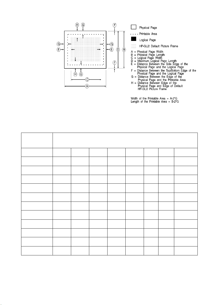
Table 2-2 Landscape Logical Page & Printable Area Boundaries
DIMENSIONS
(at 300 DPI - double for 600 DPI)
PAPER SIZE A B C D E F G H
LETTER 3300 2550 3180 2550 60 0 50 150
Legal List 1 4200 2550 4080 2550 60 0 50 150
LEDGER 5100 3300 4980 3300 60 0 50 150
EXECUTIVE 3150 2175 3030 2175 60 0 50 150
A4 3507 2480 3389 2480 59 0 50 150
A3 4960 3507 4842 3507 59 0 50 150
COM-10 2850 1237 2730 1237 60 0 50 150
MONARCH 2250 1162 2130 1162 60 0 50 150
C5 2704 1913 2586 1913 59 0 50 150
B5 2952 2078 2834 2078 59 0 50 150
DL 2598 1299 2480 1299 59 0 50 150
2-8 The Page EN
Page 43

The HP LaserJet printers perform pixel-level clipping. When printing
characters or graphics, if any portion of the character cell or graphic is
outside the printable area, only that portion outside the printable area
is clipped (see Figure 2-4).
Figure 2-4 Printable Area Character Cell Positioning
Notes Pixel level clipping can also occur at the logical page for PCL when
the page is positioned using the Left Registration command.
Pixel level clipping also occurs at the picture frame for HP-GL/2.
Characters are clipped if they fall across a margin (left, right, top, and
bottom). Refer to “Text Area” in Chapter 5 for additional information.
EN Printable Area 2-9
Page 44

2-10 The Page EN
Page 45

The Print
3
Environment
Introduction
The group of all of the printer’s current feature settings,
collectively, is referred to as the print environment. The printer
maintains four print environments: the Factory Default
Environment, the User Default Environment, the Modified
Print Environment and the Overlay Environment. This chapter
describes the Factory Default Environment, the User Default
Environment, and the Modified Print Environment (the Overlay
Environment is described in Chapter 12, Macros).
Default settings refer to the settings programmed into the printer
at the factory or settings selected using the control panel. The
term “default” simply refers to the settings the printer uses unless
printer commands select other settings.
Each time a job is printed, some of the printer’s feature settings
may be changed from their default values to produce the desired
printed output for that job. After the job prints, the job-specific
feature settings are longer be required, since the next job is likely
to have different output requirements. The next job should clear
all previous job settings by performing a reset. This allows a job
to start with the default settings as a known base set, and vary
only those settings that are needed. Starting with the default
environment at the beginning of each print job eliminates the
need to set every feature each time a job is run.
Note The print environment features presented in this chapter are for a
variety of HP LaserJet printers. Not all of the features are applicable
to every printer. To identify variations and default settings for specific
printers, refer to Chapter 3 of the PCL 5 Comparison Guide.
EN Introduction 3-1
Page 46
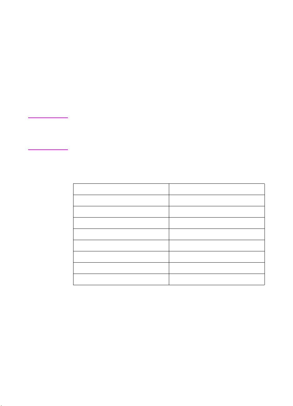
Factory Default Environment
A factory default is a feature setting programmed into the printer at
the factory. The group of all of the printer’s feature settings set to their
factory settings is referred to as the Factory Default Environment.
These features are described in this manual. Since the HP-GL/2
features are used for HP-GL/2 operation only, the print environment
features are separated, for convenience, into two lists or contexts:
PCL and HP-GL/2. Table 3-1 lists typical PCL print environment
features, and Table 3-2 lists typical HP-GL/2 print environment
features.
Note he factory default settings for the printer features are not shown here,
since they differ depending on the printer model. To identify variations
and default settings for specific printers, refer to Chapter 3 of the
PCL 5 Comparison Guide.
Table 3-1 Factory Default Print Environment Features –
PCL Context
JOB CONTROL FONTS
Number of Copies
Duplex
Binding
2
2, 3
2
Symbol Set
Spacing
Pitch
Registration Height
2
Tr ay
Manual Feed
2
Style
Stroke Weight
1
23
4
5
User-defined Units Typeface
Underlining Mode
1. The font characteristics are determined by the default font. The default font can
be the factory default font or the user-selected default font from the printer’s
control panel or from a font cartridge containing a default font.
2. User default values may be selected by the user from the printer’s control panel
for these items.
3. Selectable from the printer control panel if duplex is selected.
4. Selectable from the printer’s control panel if a fixed-space scalable font has been
selected as the user default.
5. Selectable from the printer’s control panel if a proportional scalable font has been
selected as the user default.
3-2 The Print Environment EN
Page 47
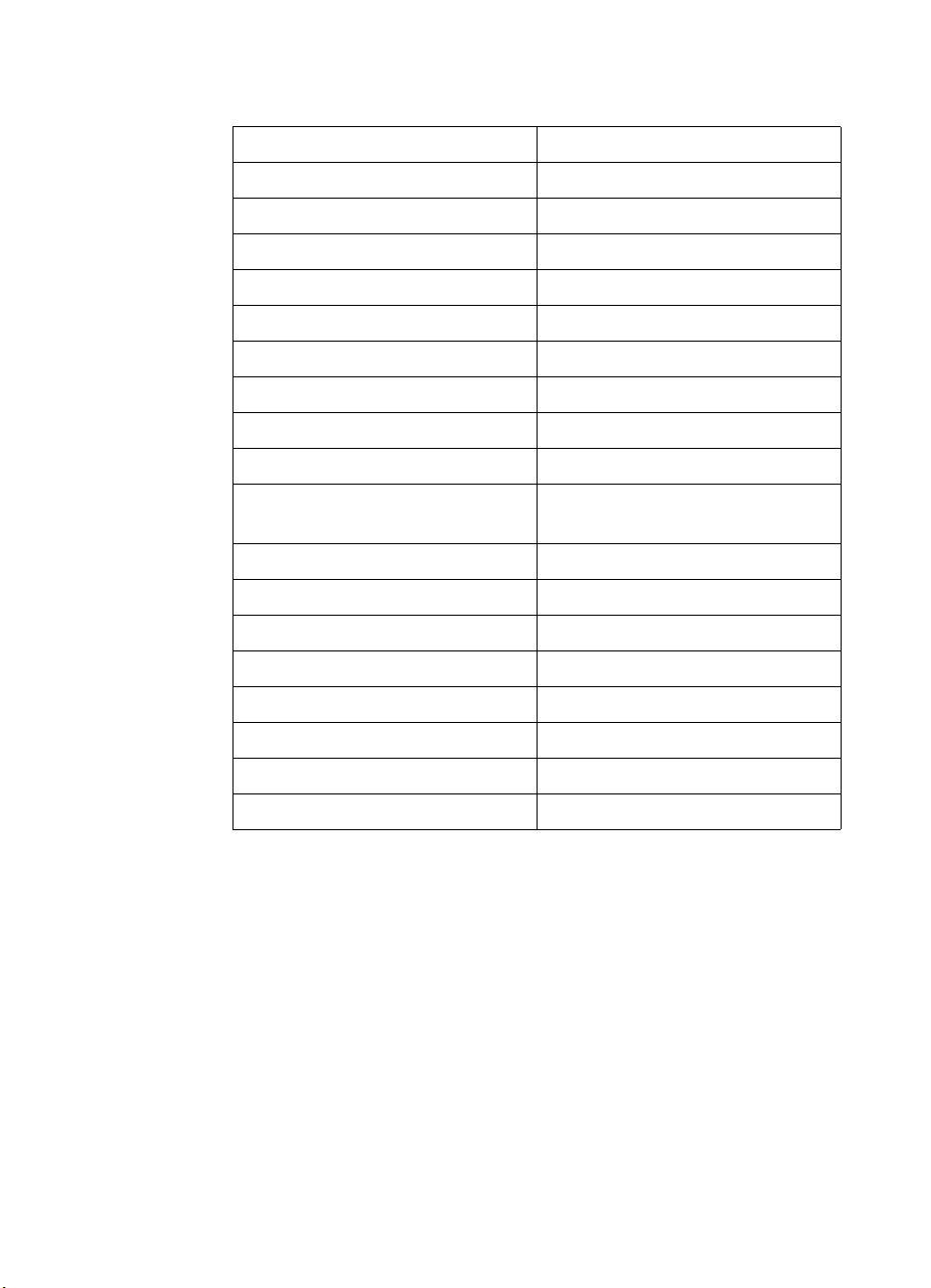
Table 3-1 Factory Default Print Environment Features –
PCL Context (continued)
PAGE CONTROL FONT MANAGEMENT
Print Direction Font ID
Orientation
Page Size
2
2
Character Code
Symbol Set ID
Paper Source RASTER GRAPHICS
Vertical Motion Index
Horizontal Motion Index
2
Left Graphics Margin
2
Resolution
Top Margin Compression Mode
Text Length Raster Height
Left Margin Raster Width
Right Margin Raster Graphics Presentation
Mode
Perforation Skip PICTURE FRAME
Line Termination Picture Frame Width
PRINT MODEL Picture Frame Height
Current Pattern Picture Frame Anchor Point
Source Transparency Mode HP-GL/2 plot Horizontal Size
Pattern Transparency Mode HP-GL/2 Plot Vertical Size
Pattern Reference Point MACRO
Pattern Rotation Macro ID
1. The font characteristics are determined by the default font. The default font can
be the factory default font or the user-selected default font from the printer’s
control panel or from a font cartridge containing a default font.
2. User default values may be selected by the user from the printer’s control panel
for these items.
3. Selectable from the printer control panel if duplex is selected.
4. Selectable from the printer’s control panel if a fixed-space scalable font has been
selected as the user default.
5. Selectable from the printer’s control panel if a proportional scalable font has been
selected as the user default.
EN Factory Default Environment 3-3
Page 48

Table 3-1 Factory Default Print Environment Features –
PCL Context (continued)
RECTANGULAR AREA FILL TROUBLESHOOTING
Horizontal Rectangle Size End-of-Line Wrap
Vertical Rectangle Size Display Functions
Pattern (Area Fill) ID
STATUS READBACK
Current Location Type
Current Location Unit
1. The font characteristics are determined by the default font. The default font can
be the factory default font or the user-selected default font from the printer’s
control panel or from a font cartridge containing a default font.
2. User default values may be selected by the user from the printer’s control panel
for these items.
3. Selectable from the printer control panel if duplex is selected.
4. Selectable from the printer’s control panel if a fixed-space scalable font has been
selected as the user default.
5. Selectable from the printer’s control panel if a proportional scalable font has been
selected as the user default.
1.
2.
3.
4.
5.
3-4 The Print Environment EN
Page 49

Table 3-2 Factory Default Print Environment Features –
HP-GL/2 Context
CHARACTER GROUP POLYGON GROUP
Symbol Set Polygon Buffer
Font Spacing Polygon Mode
Pitch LINE AND FILL ATTRIBUTE
GROUP
Height Line Type
Posture Line Type Repeat Length
Stroke Weight Line Cap
Typeface Line Join
Character Direction Miter Limit
Character Direction Mode Pen Turret
Character Size Mode Pen Width
Character Width Pen Width Selection Mode
Character Height Selected Pen
Character Slant Symbol Mode
Extra Horizontal Space Fill Type
Extra Vertical Space User-defined Line Type
Character Fill Mode Anchor Corner
Label Origin User-defined Fill Types
Label Terminator PALETTE EXTENSION
Transparent Data Mode Number of Pens
Primary Font ID Transparency Mode
Secondary Font ID Screened Vector
Scalable or Bitmap Font CONFIGURATION & STATUS
GROUP
VECTOR GROUP Scale Mode
Plotting Mode Window
Pen State Coordinate System Orientation
P1, P2
EN Factory Default Environment 3-5
Page 50

User Default Environment
There are several PCL features in the printer for which user defaults
may be selected from the printer’s control panel. User default settings
are stored in the User Default Environment and are retained even if
the printer is turned OFF. Some of these features are listed below
(for a complete set of the control panel user default features refer to
Chapter 3 of the PCL 5 Comparison Guide.)
z Number of Copies
z Font Selection (Font Source, Font Number, Pitch
z Duplex/Simplex
z Binding Edge
z
Tr ay
z Paper (Page Size: Paper and Envelopes)
z Manual Feed
z Orientation
z Symbol Set
2
Notes Refer to “Horizontal Motion Index (HMI) Command” in Chapter 5 for
the implications of setting the user default font (source, number, pitch
or point size).
1
or Point Size1)
Refer to the printer User’s Manual for instructions on how to select
these user defaults from the control panel.
The PJL (Printer Job Language) “SET” command overrides the PCL
user default environment for the duration of a PJL job. If PJL is not
active, then the PCL user default environment has precedence. Refer
to “PCL Commands” in Chapter 1 for more information.
1. For scalable typefaces: fixed-space typefaces are selected only by pitch; and
proportionally-spaced typefaces are selected only by point size.
2. Selectable only if duplex is On.
3-6 The Print Environment EN
Page 51

Modified Print Environment
The current printer feature settings constitute the Modified Print
Environment. Whenever a feature setting is altered using escape
sequences, the new setting is recorded in the Modified Print
Environment.
The Modified Print Environment is saved during a macro call or
overlay and restored upon its completion.
A Modified Print Environment consists of the current settings for the
items listed in Table 3-1 and Table 3-2, with the exception of the items
listed in Table 3-3, below.
Table 3-3 Items Not Included in Modified Print Environment
PCL Context HP-GL/2 Context
Overlay environment HP-GL/2 overlay environment
Current cursor position Duplex registration
Cursor position stack Polygon buffer
Downloaded fonts/macros
User-defined patterns
Note Not all of the Modified Print Environment features are applicable to
every printer. To identify variations and default settings for specific
printers, refer to the PCL 5 Comparison Guide.
EN Modified Print Environment 3-7
Page 52

Resetting the Print Environment
Resets are used to return the printer to a known environment.
Depending on the type of reset performed, the printer returns to either
the User Default Environment or the Factory Default Environment.
Printer Reset
A Printer Reset restores the User Default Environment and deletes
temporary fonts, macros, user-defined symbol sets, and patterns. A
Printer Reset is performed by sending the
the printer’s control panel (see the printer User’s Manual). The Printer
Reset command is described in Chapter 4, PCL Job Control
Commands.
E
The
been received. The control panel [RESET] discards any formatted
pages which have not yet been printed.
E command prints any partial pages of data that may have
C
E
E command, or through
C
Both resets (
HP-GL/2 settings to their default values.
E
E and the control panel [RESET] ) return the
C
E
E used in HP-GL/2 mode
C
returns the printer to PCL mode in addition to resetting the print
environment. The HP-GL/2 IN (Initialize) command resets HP-GL/2
settings to their default values without affecting the PCL settings
(refer to the Initialize command described in Chapter 19, The
Configuration and Status Group, for additional information).
Notes Hewlett-Packard strongly recommends the use of both the
command and the
E
%–12345X command (Universal Exit
C
Language/Start of PJL — also referred to as the UEL Command) at
the beginning and end of each job. (The order of these commands is
critical. Refer to Table 4-1 for an example of their usage.)
The UEL Command (
E
%–12345X) has the same effect as the
C
command, and also enters PJL Mode of operation for printers that
support PJL (refer to “Universal Exit Language Command” in Chapter
4 for more information). The
E
E command should be included to
C
ensure backward compatibility (the UEL command is ignored if
received by a printer that does not support PJL).
E
E
C
E
E
C
3-8 The Print Environment EN
Page 53

Cold Reset
A Cold Reset restores the Factory Default Environment which
includes resetting the control panel items to their factory default
settings. A Cold Reset is performed by power cycling the printer while
holding [ON LINE] until a 08 COLD RESET is displayed.
EN Resetting the Print Environment 3-9
Page 54

3-10 The Print Environment EN
Page 55

PCL Job Control
4
Commands
Introduction
A job typically consists of three parts:
z Commands providing job control.
z Commands providing page control.
z Print data.
Table 4-1 Structure of a Typical Job
?%–12345X UEL Command (exit language)
?E Printer Reset Command.
Preamble Job Control Commands.
Page 1 Page Control Commands.
Data
Page 2 Page Control Commands.
Data.
•
•
•
Page n Page Control Commands.
Data.
?E Printer Reset Command.
?%–12345X UEL Command (exit language).
1. If a number of consecutive pages within a job have the same format (such as
margins, VMI, HMI, etc.), the associated page control commands only need to
be sent once for that group of pages.
EN Introduction 4-1
•
•
•
1
Page 56

This chapter describes the commands providing job control. Job
control commands are usually grouped together and sent at the
beginning of a job. Page control commands and data are associated
with each printed page of a job. Job control commands include the
following:
z Printer Reset.
z Universal End of Language/Start of PJL.
z Number of Copies.
z Simplex/Duplex Print.
z Left and Top Offset Registration.
z Duplex Page Side Selection.
z Job Separation.
z Output Bin Selection.
z Unit of Measure.
Printer Reset Command
Receipt of the Printer Reset command restores the User Default
Environment, deletes temporary fonts, macros, user-defined symbol
sets and patterns. It also prints any partial pages of data which may
have been received.
? E
Notes Hewlett-Packard strongly recommends the use of both the ? E
command and the ?%–12345X command (Universal Exit
Language/Start of PJL — also referred to as the UEL Command) at
the beginning and end of each job. (The order of these commands is
critical. Refer to Table 4-1 for an example.)
The UEL Command (?%–12345X) has the same effect as the ? E
command, and also enters PJL Mode of operation for printers that
support PJL (refer to the next section, "“Universal Exit Language
Command” for more information). The ? E command should be
included to ensure backward compatibility (the UEL command is
ignored if received by a printer that does not support PJL).
4-2 PCL Job Control Commands EN
Page 57

Universal Exit Language Command
The Universal Exit Language (UEL) command causes the PCL
printer language to shut down and exit. Control is then returned to the
Printer Job Language (PJL). Both PCL 5 and HP-GL/2 recognize this
command.
? % – 1 2 3 4 5 X
Default = N/A
Range = –12345
This command performs the following actions:
z Prints all data received before the Exit Language command.
z Performs a printer reset (same effect as ? E).
z Shuts down the PCL 5 printer language processor.
z Turns control over to PJL.
Notes Hewlett-Packard strongly recommends the use of both ? E (printer
reset) and ?%–12345X (UEL command) at the beginning and end of
each job. (The order of these commands is critical. Refer to Structure
of a Typical JobTable 4-1 for an example.)
The UEL Command (?%–12345X) has the same effect as the ? E
command, and also enters PJL Mode of operation for printers that
support PJL. The ? E command should be included to ensure
backward compatibility (the UEL command is ignored if received by a
printer that does not support PJL).
EN Universal Exit Language Command 4-3
Page 58

Number of Copies Command
The Number of Copies command designates the number of printed
copies of each page.
? & l # X
# = Number of copies (1 to 32767 maximum)
Default = 1 (Configurable from control panel)
Range = 1-32767
This command can be received anywhere within a page and affects
the current page as well as subsequent pages.
(Values 32767 execute as 32767 values 1 are ignored.
Maximum number of copies=99 for LaserJet II, IIP, III, IIID, IIIP
and earlier LaserJet printers.)
Example
To print 3 copies of a page, send:
?&l3X
Figure 4-1 Number of Copies
Note The HP-GL/2 Replot (RP) command is inactive for PCL 5 printers;
use the Number of Copies command for multiple HP-GL/2 plots. To
be effective, the Number of Copies command must be issued from
PCL prior to closing the page on which the plot is defined.
4-4 PCL Job Control Commands EN
Page 59

Simplex/Duplex Print Command
This command designates either simplex or duplex printing mode for
duplex printers. Simplex mode prints an image on only one side of a
sheet (page). Duplex mode prints images on both sides of a sheet.
? & l # S
# = 0 - Simplex
1 - Duplex, Long-Edge Binding
2 - Duplex, Short-Edge Binding
Default = 0
Range = 0-2 (Other values ignored)
Long-Edge bound duplexed pages are bound along the length of the
physical page (see Figure 4-2). Short-edge bound duplexed pages
are bound along the width of the physical page (see Figure 4-3).
Selecting long-edge binding usually results in font rotation. This may
be a concern if available user memory is critical.
Note If this command is received by a printer which does not contain the
duplex feature, it is ignored. Printers which do not contain the duplex
feature print in simplex mode (front side of sheet) only.
EN Simplex/Duplex Print Command 4-5
Page 60

Figure 4-2 Long-Edge Binding Mode
Figure 4-3 Short-Edge Binding Mode
4-6 PCL Job Control Commands EN
Page 61

Left Offset Registration Command
The Left (long-edge) Offset Registration command designates the
position of the logical page across the width (short side) of the
physical page. This command can be used to adjust the text position
on the page to allow additional room for the page binding.
? & l # U
# = The number of decipoints (1/720 inch)
Default = 0
Range = –32767 to 32767
The value (#) is a signed number valid to 2 decimal places. The units
are decipoints. Positive values cause the logical page, regardless of
orientation, to move right along the width of the physical page, except
on the back side (duplex print) of sheets printed in long-edge binding
duplex mode, where positive values cause it to move left (refer to
Figure 4-4 and Figure 4-5).
Negative values cause the logical page, regardless of orientation,
to move left along the width of the physical page, except on the back
side of sheets printed in long-edge binding duplex mode, where
negative values cause it to move right (refer to Figure 4-4 and
Figure 4-5).
Notes The +/– value is absolute with respect to the default position of the
logical page along the width of the physical page. It is not relative to
the present location.
The registration commands may cause data loss by moving the
logical page outside the printable area.
This command has the same effect regardless of orientation.
This command can be used in both simplex and duplex modes.
EN Left Offset Registration Command 4-7
Page 62

Top Offset Registration Command
The Top (short-edge) Offset Registration command designates the
position of the logical page along the length (long side) of the physical
page.
? & l # Z
# = The number of decipoints (1/720 inch)
Default = 0
Range = –32767 to 32767
The value (#) is a signed number valid to 2 decimal places. The units
are decipoints. Positive values cause the logical page, regardless of
orientation, to move down along the length of the physical page,
except on the backside of sheets printed in short-edge binding duplex
mode, where positive values cause it to move up (refer to Figure 4-4
and Figure 4-5).
Negative values cause the logical page, regardless of orientation,
to move up, along the length of the physical page, except on the
backside of sheets printed in short-edge binding duplex mode, where
negative values cause it to move down (refer to Figure 4-4 and
Figure 4-5).
Notes The +/– value is absolute with respect to the default position of the
logical page along the length of the physical page. It is not relative to
the current location of the logical page.
The registration command may cause data loss by moving the logical
page outside the printable area.
This command has the same effect regardless of orientation.
This command can be used in both simplex and duplex modes.
4-8 PCL Job Control Commands EN
Page 63
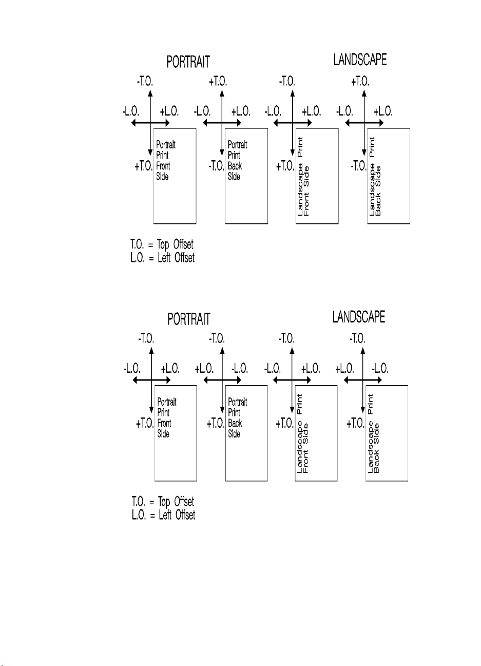
Figure 4-4 Short-Edge Binding Mode Offsets
Figure 4-5 Long-Edge Binding Mode Offsets
EN Top Offset Registration Command 4-9
Page 64

Duplex Page Side Selection Command
The Duplex Page Side Selection command causes a Form Feed and
designates which side of the sheet to print.
The ability to skip a page while duplexing may be required at certain
locations in a document. For example, a chapter typically begins on
the front side of a page.
?&a#G
# = 0 - Select next side
1 - Select front side
2 - Select back side
Default = 0
Range = 0-2 (All other values ignored)
If this command is received by a printer which does not have duplex
or if duplexing is not enabled, these commands just eject the current
page (sheet), positioning the cursor at the default position on the next
page.
Example
To print on the front side of a page, regardless of the current side,
send the following:
?&a1G
In this example, if the printer is currently formatting a front side, it will
stop formatting, eject that page (sheet, skipping the back side), and
begin printing on the next front page.
4-10 PCL Job Control Commands EN
Page 65

Job Separation Command
Job separation provides a means of identifying one print job from
others in the printer’s output tray. It usually does this by physically
offsetting one print job from the next.
The Job Separation command toggles the printer’s separation
mechanism. This command must be sent between each job to enable
the separation mechanism.
? & l 1 T
HP recommends that the Job Separation command be included at the
end of each job, just before the Printer Reset command. HP also
recommends that this command be included in the programs even
though printers with job separation are not currently being used. This
ensures that if a printer with job separation is eventually added, job
separation will be performed.
If this command is received by a printer which does not have job
separation, the command is ignored.
Note It is possible to perform job offset in printers which do not have a
mechanical offset mechanism but have dual paper trays. In dual bin
printers, job offset can be performed by placing colored paper in the
second tray and using Paper Source command to select the tray to
feed a blank sheet of colored paper at the end of a job. This method
should only be used in special cases where the end user can control
its use, for example, the program should only be available for a dual
bin printer which can always contain colored paper in one tray.
EN Job Separation Command 4-11
Page 66

Output Bin Selection Command
The Output Bin Selection command selects either of the two output
paper bins (upper or lower [rear]) for paper output.
? & l # G
# = 1 - Upper Output Bin
2 - Lower (Rear) Output Bin
Default = Upper Output Bin
Range = 1, 2
Note If this command is received by a printer which does not contain the
dual output bin feature, it is ignored.
4-12 PCL Job Control Commands EN
Page 67

Unit of Measure Command
The Unit of Measure command establishes the unit of measure for
PCL Unit cursor movements.
? & u # D
# =Number of units-per-inch
Default = 300
Range = 96, 100, 120, 144, 150, 160, 180, 200, 225, 240, 288, 300, 360,
400, 450, 480, 600, 720, 800, 900, 1200, 1440, 1800, 2400, 3600,
7200.
The value field defines the number of units-per-inch used in the
following commands:
z Vertical Cursor Position (PCL Units).
z Horizontal Cursor Position (PCL Units).
z Vertical Rectangle Size (PCL Units).
z Horizontal Rectangle Size (PCL Units).
In addition, the current unit of measure setting affects the HMI setting,
which in turn determines how cursor movement values are rounded.
This affects the result of the following commands:
z Horizontal Cursor Position (Columns).
z Horizontal Tab (HT control code).
z Space (SP control code).
z Backspace (BS control code).
z Bitmap Character Delta X (“Delta X (SI),” Chapter 11).
For example, if the unit of measure is set to 96 (one PCL Unit = 1/96
inch), then the HMI is rounded to the nearest 1/96 inch. If the unit of
measure is set to 300 (one PCL Unit = 1/300 inch), the HMI is
rounded to the nearest 1/300 inch.
Note HMI is set either as a result of font selection or through the use of
the HMI command. The rounding behavior just described only applies
when the HMI is at its default setting (derived from the currently
selected font). If the HMI Command was used to override the HMI
setting, the rounding behavior described above does not apply.
(See “Horizontal Motion Index (HMI) Command” in Chapter 5 for more
information.)
EN Unit of Measure Command 4-13
Page 68

The current unit of measure setting affects all PCL Unit moves,
horizontal and vertical rectangle size, bitmap and scalable font
metrics (how the cursor moves after printing a character). The Unit of
Measure command does not affect the interpretation of binary raster
data (bitmap fonts, raster graphics or patterns).
Once the units of measure is changed, it stays in effect until another
is selected or the printer is reset. A control panel or ? E reset returns
the current unit of measure setting back to the device default setting
(300).
The units value is part of the modified print environment. As such, it is
saved and restored whenever a macro is called or an overlay invoked,
and defaulted when establishing the overlay environment in
preparation for an overlay.
Note Values out of range are mapped to the supported value with the
minimum relative error. For example, a unit selection of 4801 would
be mapped to 7200, since the relative error (0.3332) is less than the
relative error when mapped to 3600 (0.3336):
14801 7200–
----------------------------------- 0.3332
7200
4801 3600–
--------------------------------
3600
0.3336=<=
{|4801-7200| over 7200}=0.3332 < {| 4801-3600|over 3600}=0.3336
Figure 4-6 compares a 4-unit vertical and horizontal cursor move with
a unit of measure setting of 100 versus 200 units-per-inch. Note that
the cursor move distance is halved when the Units per inch is
doubled.
4-14 PCL Job Control Commands EN
Page 69

Figure 4-6 Cursor Moves at Different Unit of Measure Settings
The printer’s physical dot size has no direct bearing on the size of
PCL Units used in cursor movements. In addition, PCL Units are not
affected by the current control panel or PJL resolution setting.
Note If no other unit of measure value has been specified, then the default
is one Unit equals 1/300 inch. In this case, a cursor movement of
450 Units moves the cursor 1.5 inches, whether printed at 300 or
600 dpi print resolution.
EN Unit of Measure Command 4-15
Page 70

4-16 PCL Job Control Commands EN
Page 71

Page Control
5
Note If a number of consecutive pages within a job have the same
Commands
Introduction
Page control commands and data are associated with each
printed page of a job. These commands determine such features
as page source, size, orientation, margins, and text spacing. This
chapter describes the commands providing page format control.
format, the associated page control commands should be sent
only once for that group of pages. Remember, once a PCL
command is set, it remains in effect until changed by another
command.
EN Introduction 5-1
Page 72

Page Size Command
The Page Size command designates the size of the paper which in
turn defines the size of the logical page.
? & l # A
PA P ER :
# = 1 - Executive (7¼ x 10½ in.)
2 - Letter (8½ x 11 in.)
3 - Legal (8½ x 14 in.)
6 - Ledger (11 x 17 in.)
26 - A4 (210mm x 297mm)
27 - A3 (297mm x 420mm)
ENVELOPES:
# = 80 - Monarch (Letter - 3 7/8 x 7½ in.)
81 - Com-10 (Business - 4 1/8 x 9½ in.)
90 - International DL (110mm x 220mm)
91 - International C5 (162mm x 229mm)
100 - International B5 (176mm x 250mm)
Default = 2 (Configurable from Control Panel)
Range = 1, 2, 3, 6, 26, 27, 80, 81, 90, 91, 100 (Other values ignored)
Note Refer to the “PCL Feature Support Matrix” in Chapter 1 of the PCL 5
Comparison Guide or the printer User’s Manual for lists of supported
paper and/or envelope sizes on specific printers.
Upon receipt of this command any unprinted pages are printed, the
top margin, text length, and left and right margins are set to their user
defaults, and any automatic macro overlay is disabled. The cursor is
moved to the left edge of the logical page at the top margin on the
following page (see Figure 5-5). Also, certain HP-GL/2 state variables
are reset (refer to Table 5-1, under “Sending a Page Size
Command:”).
The factory default Page Size is Letter (A4 for 220v option printer);
however, a user default Page Size may be selected from the control
panel. The Page Size command takes precedence over the printer’s
control panel FORM setting.
5-2 Page Control Commands EN
Page 73

If the Page Size command selection differs from that of the installed
paper tray size and the requested page size is not currently available
in another non-secure source, then a message is displayed on the
control panel requesting installation of a paper tray of the specified
size.
Note The Page Size command is not supported on the HP LaserJet,,
LaserJet+, or the LaserJet 500+ printers.
Example
To select a legal size page, send:
? & l3A
If the current source paper tray is “LETTER” and the requested page
size is not currently available in another non-secure source the
following attendance message is displayed:
1
xx
‘‘LOAD LEGAL’’
1 xx = A two-letter mnemonic depending on the printer.
When the printer senses the existing paper supply has been removed
and replaced with the requested paper size, the print job continues
automatically.
EN Page Size Command 5-3
Page 74

PAPER SOURCE COMMAND
The Paper Source command designates the location to feed paper, or
it prints the current page.
? & l # H
# = 0 - Print the current page
(paper source remains unchanged).
1 - Feed paper from the a printer-specific tray.
2 - Feed paper from manual input.
3 - Feed envelope from manual input.
4 - Feed paper from lower tray.
5 - Feed from optional paper source.
6 - Feed envelope from optional envelope. feeder
1 Must be used in conjunction with Page Size command, envelope selection.
Default = Printer Dependent (Configurable from Control Panel)
Range = Printer Dependent
Note Not all HP LaserJet printers support all possible paper sources. The
implementation of paper source locations varies slightly from printer
to printer. Refer to the “PCL Feature Support Matrix” in Chapter 1 of
the PCL 5 Comparison Guide or the printer User’s Manual for paper
source feature implementation details for specific HP LaserJet
printers.
1
The Paper Source command causes the current page to be printed
and the cursor to be moved to the left edge of the logical page at the
top margin position for the next page (see Figure 5-5).
Example
To feed paper from the manual feed slot, send:
?&l2H
If the selection requires operator action (such as manually feeding
paper), a printer message appears in the display, prompting for the
appropriate action (see the printer User’s Manual for specific
behavior).
5-4 Page Control Commands EN
Page 75

Logical Page Orientation Command
Orientation defines the position of the logical page and the default
direction of print with respect to the physical page as shown in
Figure 5-1.
? & l # O
# = 0 - Portrait
1 - Landscape
2 - Reverse Portrait
3 - Reverse Landscape
Default = 0
Range = 0-3 (Other values ignored)
Notes This command can be used only once per page. To print multiple
directions per page use the Print Direction command.
This command affects the HP-GL/2 environment (refer to Table 5-1
and the ***“HP-GL/2 and PCL Orientation Interaction” section in
Chapter 15 for additional information).
The Orientation command causes the page length, top margin, text
length, left and right margins, horizontal motion index (HMI), and
vertical motion index (VMI) to return to their user default values, and
disables the automatic macro overlay. All data received prior to this
command is printed, and a Form Feed and Carriage Return executed.
The cursor is moved to the left edge of the logical page at the top
margin cursor position (see Figure 5-5).
The factory default orientation is portrait. Landscape orientation may
be selected as the user default orientation using the control panel.
Note The HP LaserJet 2000, LaserJet IID, LaserJet IIP and all PCL 5
printers automatically rotate all fonts to the current orientation.
Table 5-1 shows how changing certain PCL features (such as a reset,
orientation, page size or page length) or changing the HP-GL/2
picture presentation directives (picture frame width or height,
horizontal or vertical plot size, or picture frame anchor point) affect the
HP-GL/2 state variables.
EN Logical Page Orientation Command 5-5
Page 76

Table 5-1 HP-GL/2 State Variables
?E
or
Control Panel Reset:
Changing Orientation
or
Sending a Page Size
Command:
Redefinition of the
horizontal
and/or vertical
picture frame:
z executes “IN” command
z defaults picture frame
z defaults picture frame anchor
point
z defaults HP-GL/2 plot size
z Defaults picture frame anchor
point.
z Defaults picture frame.
z Defaults HP-GL/2 plot size.
z Defaults P1 and P2 (“IP;”).
z Defaults soft-clip window
(“IW;’”).
z Clears the polygon buffer
(“PM0;PM2”).
z Updates the current position to
the lower-left corner of the
picture frame (P1).
z Defaults P1 and P2 (“IP”).
z Defaults soft-clip window (“IW”).
z Clears the polygon buffer
(“PM0;PM2”).
z Updates the current position to
the lower-left corner of the
picture frame (P1).
Redefinition of the Picture
Frame Anchor Point:
z Defaults P1 and P2 (“IP”).
z Defaults soft-clip window (“IW”).
z Clears the polygon buffer
(“PM0;PM2”).
z Updates the current position to
the lower-left corner of the
picture frame (P1).
Specifications of a New
HP-GL/2 Plot Size:
z Changes the picture frame
scaling factor.
5-6 Page Control Commands EN
Page 77

Figure 5-1 Page Orientation With Default Print Direction
The orientation of the HP-GL/2 picture is also affected by the logical
page orientation. Figure 5-2 illustrates the effect of logical page
orientation on the HP-GL/2 picture orientation. It is possible to alter
the HP-GL/2 picture orientation within the logical page using the
HP-GL/2 RO command (refer to Chapter 21, for additional
information).
Most HP-GL/2 state variables retain their previous HP-GL/2 value
upon receipt of this command (they are not affected by PCL mode).
However, certain changes to the PCL state can affect the HP-GL/2
state (see Table 5-1).
EN Logical Page Orientation Command 5-7
Page 78

Figure 5-2 HP-GL/2 Picture Orientation with Respect to
Logical Page Orientation
5-8 Page Control Commands EN
Page 79

Print Direction Command
The Print Direction command rotates the logical page coordinate
system with respect to the current orientation without performing a
page eject. This rotation is performed in 90° increments in a
counterclockwise direction. This allows printing in four directions on
the same page.
? & a # P
# = 0 - 0° rotation.
90 - 90° ccw rotation.
180 - 180° ccw rotation.
270 - 270° ccw rotation.
Default = 0
Range = 0, 90, 180, 270 (Other values ignored)
Changing the print direction causes the following:
z The print origin moves with the logical page rotation. For
example, rotating a default page (portrait orientation, 0° print
direction) 90° causes data to print in the landscape direction
across the “portrait” page.
z The margins are translated (when the print direction changes by
90°, the left margin becomes the new top margin, the former top
margin becomes the new right margin, etc.)
z The cursor position remains at the same physical location.
z All subsequent printing (characters, area fill patterns, raster
images) is rotated to coincide with the new print direction.
z Any current raster graphics end when the print direction changes.
z Print Direction does not default HMI.
Note The Print Direction Command does not affect HP-GL/2 vector graphic
images. HP-GL/2 graphics can be rotated only with the Orientation
command (?&l#O) or the HP-GL/2 “RO” command.
EN Print Direction Command 5-9
Page 80

Figure 5-3 Changing Print Direction on a Page
5-10 Page Control Commands EN
Page 81

Text Area
Text printing may be restricted to a specific area within the logical
page using the Left Margin, Right Margin, Top Margin, Text Length,
and Perforation Skip Mode commands. This area is known as the
text area.
The left margin defines the distance between the left edge of the
logical page and the left edge of the text area. The right margin
defines the distance between the left edge of the logical page and the
right edge of the text area. The width of the text area is the distance
between the left and right margins. The top margin defines the
distance between the top of the logical page and the top of the text
area. The text length defines the length of the text area which in effect
defines the bottom margin. The perforation region is the distance from
the bottom of the text area to the top of the text area (top margin) on
the next page. The text area is shown in Figure 5-4.
In general, characters are printed when they fall within the text area.
However, characters can be printed between the bottom of the text
area and the top of the text area on the next page only if perforation
skip is disabled. Characters are printed outside the text area if a
cursor move escape sequence positions the cursor outside the text
area (but within the printable area). Characters that fall on (or outside)
a margin as a result of printing a character string, are clipped
(not printed).
Notes Attempting to print characters across a margin results in the
characters being discarded.
The default text area and the default HP-GL/2 picture frame are
the same.
EN Text Area 5-11
Page 82

Figure 5-4 Text Area Within the Page
5-12 Page Control Commands EN
Page 83

Left Margin Command
The Left Margin command sets the left margin to the left edge of the
specified column.
? & a # L
# = Column number
Default = Column 0 (Left bound of logical page)
Range = 0 - Right margin
The first column within a line is column 0, which is located at the left
edge of the logical page (the HMI setting defines the distance
between columns, which thereby defines the maximum number of
columns on the logical page). If the value field specifies a column
greater than the current right margin, the command is ignored.
Margins represent a physical position and once set do not change
with subsequent changes in HMI.
If the cursor is to the left of the new left margin, the cursor is moved to
the new left margin.
Example
To set the left margin to column 5, send:
?&a5L
EN Left Margin Command 5-13
Page 84

Right Margin Command
The Right Margin command sets the right margin to the right edge of
the specified column.
? & a # M
# = Column number
Default = Logical Page right bound
Range = Current left margin - Logical page right bound
The maximum right column is located at the right edge of the logical
page (the HMI setting defines the distance between columns, which
thereby defines the maximum number of columns on the logical
page). If the value field specifies a column which is greater than the
right edge of the logical page, the right margin is set to the right edge
of the logical page. If the value field specifies a column less than the
left margin, the command is ignored.
Margins represent a physical position and once set do not change
with subsequent changes in HMI.
If the cursor position is to the right of the new right margin, the cursor
is moved to the new right margin.
Example
To set the right margin to column 45, send:
?&a45M
5-14 Page Control Commands EN
Page 85

Clear Horizontal Margins Command
The Clear Horizontal Margins command resets the left and right
margins. The left margin is set to the left edge of the logical page
(column 0) and the right margin is set to the right edge of the logical
page.
? 9
EN Clear Horizontal Margins Command 5-15
Page 86

Top Margin Command
The Top Margin command designates the number of lines between
the top of the logical page and the top of the text area.
? & l # E
# = Number of lines
Default = 1/2 inch down from top of logical page
Range = 0 - Length of logical page (Other values ignored)
1 If logical page length is <½inch, then the top margin is set to top of logical page.
The Top Margin command is ignored if the value field (#) is greater
than the current logical page length or if the current VMI is 0 (VMI
defines the distance between lines of text).
Receipt of a Top Margin command resets the text length according to
the following equation:
The top margin represents a physical position and once set does not
change with subsequent changes in VMI or line spacing.
The vertical cursor position for the first line of print is determined by
the current values of the top margin and VMI using the following
equation:
Note The default cursor position is not located at the intersection of the
top margin and the left bound of the logical page (refer to Figure 5-5).
The cursor is actually positioned down 75% of the VMI distance
(0.75 × VMI) from the top margin. This positions the cursor at the
relative base line position of a character cell for correct character
positioning.
1
Example
To set the top margin to line 4, send:
?&l4E
5-16 Page Control Commands EN
Page 87

Note The first line of the logical page is line 0.
Figure 5-5 Margin Cursor Positioning
EN Top Margin Command 5-17
Page 88

Text Length Command
The Text Length command designates the number of lines (at a given
VMI) within the logical page available for printing text, the text area.
This effectively defines the bottom margin.
? & l # F
# = Number of lines
Default = 1/2 inch less than maximum text length1
Range = Logical page length minus top margin
1 Maximum text length = INT(logical page length - top margin). However, if the max
text length is less than ½inch, the text length is set to the maximum allowable.
The value field (#) sets the text length in lines referenced from the top
margin. If a value greater than the logical page length minus the top
margin is specified or if the current VMI is 0, the command is ignored.
The user default text length is invoked whenever the orientation, page
length, page size, or top margin is changed. The user default text
length is computed as follows:
Note The user default VMI is selectable using the control panel; VMI is
calculated from the FORM menu setting.
Example
To select a text length of 60 lines, send:
?&l6ØF
5-18 Page Control Commands EN
Page 89

Perforation Skip Command
The perforation region is the distance from the bottom of the text area
of one page to the top of the text area (top margin) of the next page.
When perforation skip is enabled, a Line Feed or Half-Line Feed,
which would move the cursor beyond the bottom of the text area,
causes the cursor to move to the top of the text area on the next page.
When perforation skip is disabled, a Line Feed or Half-Line Feed
allows the cursor to move to the next line or half-line in the perforation
region, allowing printing to continue there.
? & l # L
# = 0 - Disable
1 - Enable
Default = 1
Range = 0-1 (Other values ignored)
Whenever the perforation skip mode is changed, the top margin and
page length are returned to their default values.
Note When perforation skip is disabled, some print lines can fall outside the
printable area and be lost. If lines of data could fall into the
unprintable area, perforation skip should be enabled.
EN Perforation Skip Command 5-19
Page 90

Horizontal Motion Index (HMI) Command
The Horizontal Motion Index (HMI) command designates the width of
the columns.
? & k # H
# = Number of 1/120 inch increments.
Default = Determined by the pitch value in the default font header.
Range = 0 - 32767 (valid to four decimal places)
The value field is valid to 4 decimal places. A value of zero (0)
indicates no horizontal motion.
When fixed pitch fonts are selected, all printable characters including
the Space and Backspace characters are affected by HMI. When
proportional fonts are selected, the HMI affects only the Space control
code character.
HMI is reset to match the new font when any of the font
characteristics are changed and when switching between primary
and secondary fonts with Shift In and Shift Out.
HMI is equal to the pitch value in the font header. The factory default
font’s HMI is 12 (12/120 = 1/10 inch per character, or 10 characters
per inch).
Note When HMI is not specifically set using the HMI command, PCL cursor
moves are rounded to the nearest full increment determined by the
current unit of measure setting. For example, if the unit of measure is
set to 96 (one PCL Unit = 1/96 inch), then the HMI is rounded to the
nearest 1/96 inch. If the unit of measure is set to 300 (one PCL Unit =
1/300 inch), the HMI is rounded to the nearest 1/300 inch.
5-20 Page Control Commands EN
Page 91

Example
To print the printer’s resident 16.66 pitch Line Printer font at 17.75 cpi,
send ?(s16.66H to select the Line Printer font, then send the
command ?&k6.76H to change HMI. This value field is calculated
as follows:
Each character then occupies 6.76/120 inch or 1/17.75 inch.
To use Courier 12 point (10 cpi) and print 80 characters across A4
paper, requires adjusting the HMI value. The HMI value is calculated
as follows:
* This value was obtained from Figure 2-3 which identifies the page sizes
(in 300 dpi dots).
EN Horizontal Motion Index (HMI) Command 5-21
Page 92
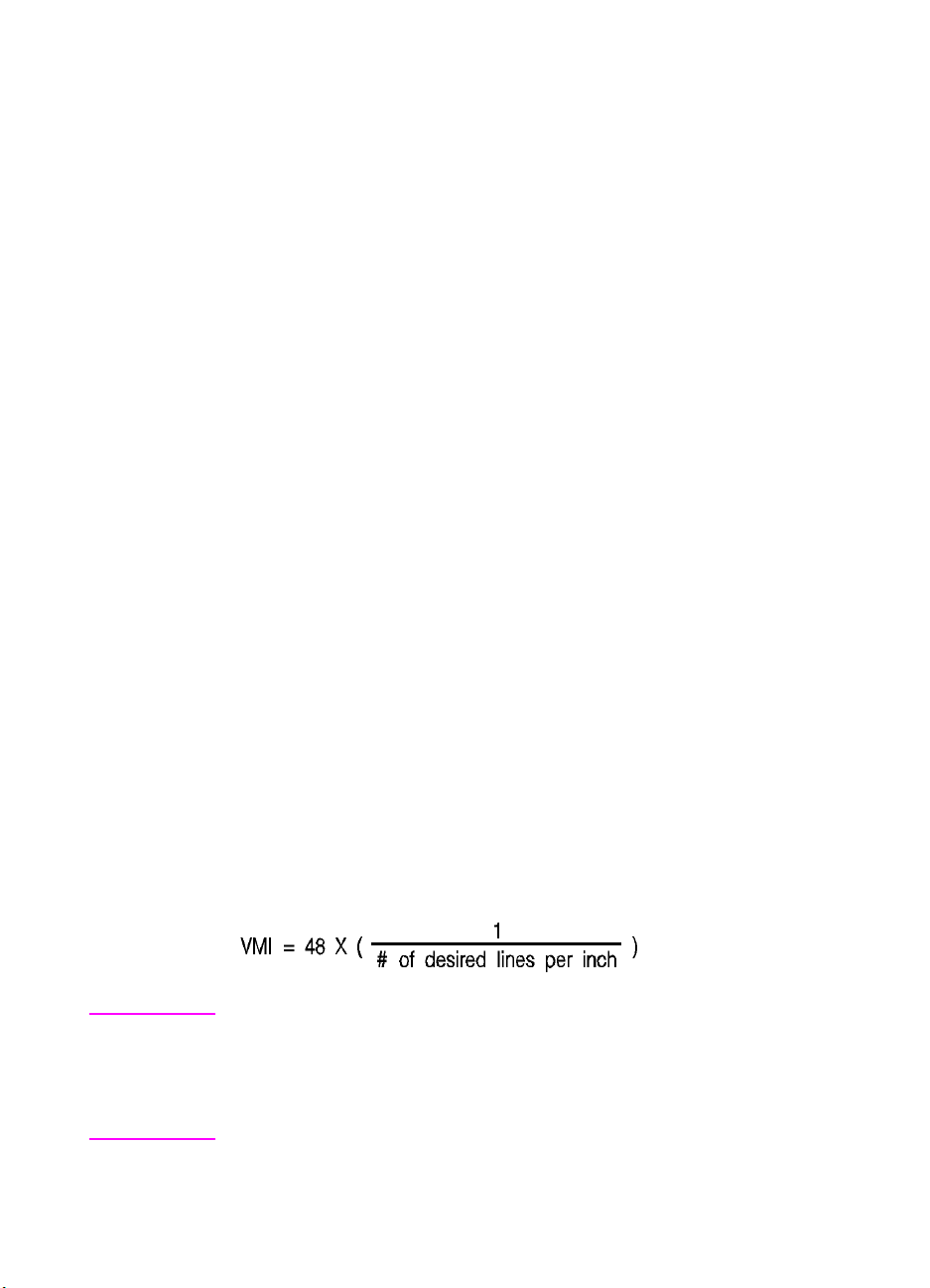
Vertical Motion Index (VMI) Command
The Vertical Motion Index (VMI) command designates the height of
the rows. (The vertical distance the cursor moves for a Line Feed
operation.)
? & l # C
# = number of 1/48 inch increments between rows.
Default = 8
Range = 0 - Current logical page length up to a maximum of 32767
If the specified VMI is greater than the current logical page length, the
command is ignored.
The value field is valid to 4 decimal places. A Ø in the value field
indicates no vertical movement.
This command affects the Line Feed and Half-Line Feed spacing.
The factory default VMI is 8, which corresponds to 6 lines-per-inch. A
user default VMI can be selected from the control panel using the
FORM menu item (refer to the printer User’s Manual for additional
information).
Example
To designate a VMI of 6 (8 lines-per-inch) send:
?&l6C (6/48 = 1/8 inch/line)
The following equation converts lines-per-inch spacing to VMI:
Note A change in the control panel FORM setting results in a modification
of VMI. If the Page Length command (?&l#P) follows a VMI change,
the physical size of the page is recalculated. Therefore, depending on
the VMI modification made, the printer may request a different paper
size.
5-22 Page Control Commands EN
Page 93

Common VMI Settings
To print 66 lines per page on letter-size paper, in portrait orientation
(with one-half inch top and bottom margins) send:
?&l7.27C 7.27 = (10/66) x 48
To print 66 lines per page on letter or legal-size paper, in landscape
orientation (with one-half inch top and bottom margins) send:
?&l5.45C 5.45 = (7.5/66) x 48
EN Vertical Motion Index (VMI) Command 5-23
Page 94

Line Spacing Command
The Line Spacing command sets the number of lines printed per inch.
Only the values listed below are valid.
? & l # D
# = 1 - 1 lpi
2 - 2 lpi
3 - 3 lpi
4 - 4 lpi
6 - 6 lpi
8 - 8 lpi
12 - 12 lpi
16 - 16 lpi
24 - 24 lpi
48 - 48 lpi
Default = 6
Range = 0,1,2,3,4,6,8,12,16,24,48 (Other values are ignored)
This command performs the same function as the Vertical Motion
Index (VMI) command except that it identifies the VMI in
lines-per-inch (lpi).
The factory default lines-per-inch setting is 6. A user default line
spacing can be selected from the control panel using the FORM
menu item.
Example
To select 12 lpi, send:
?&l12D
Note Once a PCL command sets a parameter, that parameter remains in
effect until another command changes it. The most recently received
command has precedence.
5-24 Page Control Commands EN
Page 95

6
Cursor Positioning
Introduction
This section describes the cursor positioning commands.
Although the printer does not actually have a cursor, the PCL
cursor position refers to the Current Active Position (CAP), like
the blinking underline character (cursor) used on most
computers. This “cursor” identifies the current position on the
page; the pointer, where a printing command begins laying out
page data. The cursor can be moved anywhere within the logical
page using a combination of horizontal and vertical cursor
positioning commands and control codes.
In addition to cursor commands positioning the cursor, the cursor
is automatically positioned after certain operations, such as
printing characters and graphics. After printing a character, the
cursor is positioned to the right, at a distance equal to the width
of that character. This is controlled by the character design
described under “Character Width” in Chapter 10, and allows
printing characters without requiring a cursor position command
for each character printed. When printing graphics, the cursor
can also be positioned at a new location. These new positions
are identified in the graphics sections.
HP-GL/2 vector graphics has its own HP-GL/2 cursor (referred
to as the “pen”) that can be positioned within the HP-GL/2
addressable area. For additional information on HP-GL/2 pen
positioning refer to Chapter 17, An Introduction to HP-GL/2
Vector Graphics.
EN Introduction 6-1
Page 96

Absolute vs. Relative Cursor Positioning
Either absolute or relative motion can be specified.
Absolute motion always specifies the distance to move referenced
from the top margin at the left bound of the logical page (0,0),
regardless of the current active position (CAP) (see Figure 6-1). An
unsigned value field in a cursor position command indicates absolute
cursor movement.
Relative motion specifies the distance to move referenced from the
current active position (CAP) (see Figure 6-1). A signed (+/-) value
field in a cursor position command indicates relative cursor
movement.
Figure 6-1 Absolute and Relative Cursor Positioning
6-2 Cursor Positioning EN
Page 97

Cursor Positioning Units
Cursor positioning is done in PCL coordinate system units. The units
of the X-axis of the PCL coordinate system may be PCL Units,
decipoints, or columns. The units of the Y-axis of the PCL
coordinate system may be PCL Units, decipoints, or rows.
PCL Units
The current unit size used in PCL Unit moves is determined by the
value specified in the Unit of Measure command, defining the number
of units-per-inch used in the following commands:
z Vertical Cursor Position (PCL Units).
z Horizontal Cursor Position (PCL Units).
z Vertical Rectangle Size (PCL Units).
z Horizontal Rectangle Size (PCL Units).
In addition, the current unit of measure setting affects how cursor
movement values are rounded, in turn affecting the result of the
following commands:
z Horizontal Cursor Position (Columns).
z Horizontal Tab (HT control code).
z Space (SP control code).
z Backspace (BS control code).
z Bitmap Character Delta X (Delta X (SI), Chapter 11).
For more information, refer to the next section, “Horizontal Cursor
Positioning (Columns) Command.”
If no unit of measure value is specified, the default number of
units-per-inch for PCL Unit moves (horizontal and vertical rectangle
size, etc.) is one Unit equals 1/300 inch. This is true even when a
different resolution (such as 600 dpi) is selected on the printer.
EN Cursor Positioning Units 6-3
Page 98

Decipoints
In PCL terminology, a decipoint is 1/720 inch or one-tenth of a PCL
point (a PCL point is exactly 1/72 inch as opposed to a typographic
point which is approximately 1/72 inch).
Columns & Rows
The width of a column is defined by the current horizontal motion
index (HMI), as described under “Horizontal Motion Index (HMI)
Command” in Chapter 5. The distance between rows is defined by the
current vertical motion index (VMI), as described under “Vertical
Motion Index (VMI) Command” in Chapter 5. HMI is the distance
between consecutive characters. VMI is the distance between
consecutive lines of text. HMI and VMI are described in more detail in
Chapter 5.
HP-GL/2 has its own coordinate system and units. For additional
information about the HP-GL/2 coordinate system and units, refer to
Chapter 17, An Introduction to HP-GL/2 Vector Graphics.
6-4 Cursor Positioning EN
Page 99

Horizontal Cursor Positioning (Columns) Command
This Horizontal Cursor Positioning command moves the cursor to a
new column on the current line.
? & a # C
# = Number of Columns
Default = NA
Range = 0 - logical page right bound (valid to 4 decimal places)
The width of a column is defined by the current HMI.
Note The current unit of measure setting affects how HMI values are
rounded. For example, if the unit of measure is set to 96 (one
PCL Unit = 1/96 inch), then the HMI is rounded to the nearest 1/96
inch. If the unit of measure is set to 300 (one PCL Unit = 1/300 inch),
the HMI is rounded to the nearest 1/300 inch.
A value field (#) with a plus sign (+) indicates the new position is to
the right of and relative to the current cursor position; a minus sign (–)
indicates the new position is to the left of and relative to the current
cursor position. No sign indicates an absolute distance which is
referenced from the left edge of the logical page. The first column
within a line is column 0. This sequence ignores margins and can
therefore be used to set the current active position (CAP) to any
location along the current line.
If a request is made for a location outside the printer’s logical page,
the CAP is moved to the appropriate logical page limit.
EN Horizontal Cursor Positioning (Columns) Command 6-5
Page 100

Horizontal Cursor Positioning (Decipoints) Command
This Horizontal Cursor Positioning command moves the cursor to a
new position along the horizontal axis.
? & a # H
# = Number of Decipoints (1/720 inch)
Default = NA
Range = 0 - logical page right bound (rounded to the first decimal place)
A value field (#) with a plus sign (+) indicates the new position is to
the right of and relative to the current cursor position; a minus sign (–)
indicates the new position is to the left of and relative to the current
cursor position. No sign indicates an absolute distance which is
referenced from the left edge of the logical page. The left most
position is 0 and the right most position is the right bound of the
logical page.
If a request is made for a location outside the printer’s logical page,
the current active position (CAP) is moved to the appropriate logical
page limit.
The value field is valid to two decimal places.
6-6 Cursor Positioning EN
 Loading...