

Page 1
PCL 5 Printer Language
Technical Reference Manual
ABCDE
HP Part No. 5961-0509
Printed in USA
First Edition - October 1992
Page 2
Notice
HEWLETT-PACKARD MAKES NO WARRANTY OF
ANY KIND WITH REGARD TO THIS MATERIAL,
INCLUDING, BUT NOT LIMITED TO, THE
IMPLIED WARRANTIES OF MERCHANTABILITY
AND FITNESS FOR A PARTICULAR PURPOSE.
Hewlett-Packard shall not be liable for errors contained
herein or for incidental or consequential damages in
connection with the furnishing, performance, or use of
this material.
This document contains proprietary information whichis
protected by copyright. All rights are reserved. No part
of this do cument may be photo copied, repro duced, or
translated to another language without the prior written
consent of Hewlett-Packard Company. The information
contained in this document is subject to change without
notice.
c
Copyright 1992 Hewlett-Packard Company
Page 3

Printing History
This document is the current edition of the technical reference manual
for PCL 5 and earlier printers. It replaces the September 1990 edition of
the
33459-90903). If you have ordered another PCL Technical Reference
document, this manual and the
updated replacement do cuments.
This manual was created using
on an HP Vectra Personal Computer. The bo dy text is
printed in
copywas printed on an HP LaserJet IIISi printer with
Resolution Enhancement technology (RET) and was
then repro duced using standard oset printing.
First Edition | October 1992
HP PCL 5 Printer Language Technical Reference Manual
Century Schoolbook
NOTICE
PCL 5 Comparison Guide
HP Tag/Vectra
fonts. The camera-ready
are the
software
(p/n
iii
Page 4
Trademark Credits
Intellifont
trademarks of Agfa Division, Miles Inc.
and
Shannon
and
Garth Graphic
are U.S. registered
CG Triumvirate
are trademarks of Agfa Division, Miles Inc.
CG Bodoni,CG Century Schoolbook,CG Goudy Old
Style,CG Mel liza,Microstyle,CG Omega,CG Palacio
CG Times
Agfa Division, Miles Inc.
Division, Miles Inc., is based on
and
CG Trump Mediaeval
CG Times
are products of
, a product of Agfa
Times New Roman
,
a U.S. registered trademark of Monotype Corporation
plc.
PCL
, and
Vectra
Hewlett-Packard Company.
a trademark of Hewlett-Packard Company.
are U.S. registered trademarks of
Resolution Enhancement
IBM
is a
is
registered trademark of International Business Machines
Corporation.
Microsoft,Windows
, and
MS-DOS
are
U.S. registered trademarks of Microsoft Corporation.
TrueType
of Apple Computer, Inc.
trademark of Adob e Systems, Inc.
registered trademark of Centronics Corp oration.
and
Macintosh
are registered trademarks
PostScript
is a registered
Centronics
is a U.S.
ITC
Avant Garde Gothic,ITC Benguiat,ITC Bookman,ITC
Cheltenham,ITC Gal liard,ITC Korinna,ITC Lubalin
Graph,ITC Souvenir,ITC Zapf Chancery
Dingbats
Typeface Corporation.
are U.S. registered trademarks of International
ITC Tiany
is a trademark of
International Typeface Corporation.
Futura
and
ITC Zapf
is a U.S.
registered trademark of Fundicion Tipograca Neufville,
S.A.
Serifa
Neufville, S.A.
Esselte Pendaex Corporation.
Roman
Helvetica
AG and its subsidiaries.
trademark of Linotype AG and its subsidiaries.
Olive
Arial
is a trademark of Fundicion Tipograca
Letraset
is a registered trademark of
Revue
and
University
are trademarks of Esselte Pendaex Corporation.
and
Times Roman
are trademarks of Linotype
Univers
is a U.S. registered
Antique
is a trademark of Monsieur Marcel OLIVE.
and
Gill Sans
are registered trademarks of The
Monotype Corporation plc.
,
iv
Page 5
Inside This Manual
What You Can Learn
From This Manual
Hewlett-Packard has developed a standard set of printer
features for use in all HP printers. Printer features
are accessed through the corresponding commands of
Hewlett-Packard's PCL language. This manual describes
the PCL 5 printer language. This includes descriptions
of the commands available for Hewlett-Packard PCL
5 LaserJet printers and the basic requirements of
PCL language programming. With the release of new
LaserJet family printers there are new features added
which supplement the existing PCL base set. Features of
future printer releases are not covered in this do cument.
The new features are described in the latest version of
the
PCL 5 Comparison Guide
. Programmers should
familiarize themselves with the information provided
in the
PCL 5 Comparison Guide
in addition to the
information in this do cument.
Experienced Users
This manual was written for people with some
programming experience. Many of the concept
discussions assume some programming knowledge.
When writing a PCL language program, you should
know the PCL language concepts and commands
presented in this manual, and should be aware of the
dierences in implementation of the PCL 5 printer
language for the various HP LaserJet printers, as
described in the
PCL 5 Comparison Guide
.
Non-technical Users
Many software applications (word processing software,
spreadsheets, etc.) allowyou to embed printer
commands as
escape sequences
in the bo dy of your
documents. This manual presents the full syntax and
v
Page 6
explanation of all the commands supported by PCL 5
LaserJet printers. These commands enable you to take
advantage of the LaserJet printer's advanced feature set.
Note
Since actual implementation of printer commands within
software applications varies from package to package,
specic examples are not given. For examples of printer
command usage with many popular software packages,
refer to HP's
Software Application Notes,
provided with
the printer. The most currentversions of software
application notes can be obtained through the HP
Forum on CompuServe, by fax using the HP FIRST fax
service, or through HP's literature distribution. Refer to
Appendix A for more information.
Chapter Summaries
A brief description of eachchapter is provided below.
Chapter 1 - Introduction to HP PCL
This chapter gives a brief history of the development
of the PCL language, describ es the PCL language
levels (architecture), and describes the PCL command
structure (control codes and escap e sequences).
Chapter 2 - The Page
This chapter introduces the idea of the logical page and
identies the area in which printing can o ccur. It also
describes the PCL co ordinate system and the HP-GL/2
picture frame.
Chapter 3 - The Print Environment
This chapter introduces the printer's feature settings,
collectively, as the printenvironment. It includes
descriptions of the factory default environment,
user default environment, and the modied print
environment. The eect of printer reset functions is also
described.
vi
Page 7
Chapter 4 - Job Control Commands
This chapter describes the commands which provide job
control. Job control commands are usually grouped
together and sent at the beginning of a job. Job control
includes restoration of the User Default Environment,
selection of the number of copies of each page to be
printed, duplex print commands, and unit of measure
specication.
Chapter 5 - Page Control Commands
This chapter describes the commands providing page
format control. Page format control allows you to select
the page source, size, orientation, margins, and text
spacing.
Chapter 6 - Cursor Positioning
This chapter describes how to position the cursor within
the logical page.
Chapter 7 - Fonts
This chapter describes basic font information including
fontcharacteristics.
Chapter 8 - Font Selection
This chapter describes how to select a font for printing
using the fontcharacteristics commands. The underline
feature is describ ed at the end of the chapter.
Chapter 9 - Font Management
This chapter describes font management which provides
mechanisms for downloading and manipulating soft
fonts.
Chapter 10 - User-Dened Symbol Sets
This chapter describes the capability of some PCL 5
printers to enable users to dene their own symbol sets
for special needs.
Chapter 11 - Soft Font Creation
This chapter describes how to organize font/character
data for downloading to the printer.
vii
Page 8
Chapter 12 - Macros
This chapter describes macro commands which store a
block of PCL commands and data which can b e used
repeatedly without redening the block. The macro
function reduces the number of commands that must be
sent to the printer.
Chapter 13 - The PCL Print Model
This chapter describes the PCL print model which allows
for special eects when printing.
Chapter 14 - PCL Rectangular Area Fill Graphics
This chapter describes how to dene and ll a
rectangular area with one of the predened PCL
patterns, or with a user-dened pattern.
Chapter 15 - Raster Graphics
This chapter describes howtodownload raster graphics
to the printer, and includes various techniques for
reducing the amount of data needed to dene the raster
image.
Chapter 16 - Status Readback
This chapter describes the PCL status readback features.
Status readback enables you to obtain PCL status
information from the printer, such as: available printer
(user) memory, a list of fonts and symbol sets, and the
ID numbers of macros and user-dened patterns.
viii
Chapter 17 - An Introduction to HP-GL/2 Graphics
This chapter introduces basic information for HP-GL/2.
It lists the vector graphics commands, and describes
the HP-GL/2 command syntax. An overview of several
important topics is also provided, such as the PCL
Picture Frame concept, scaling, pen status and lo cation,
and absolute vs. relative pen movement.
Page 9
Chapter 18 - The Picture Frame
This chapter describes how to set up an area on the page
for printing vector graphics (the PCL Picture Frame). It
discuses the commands necessary to dene and position
the picture frame, along with the commands used to
enter and exit HP-GL/2 mode.
Chapter 19 - The Conguration and Status Group
This chapter describes the commands used to set default
conditions and values for programmable HP-GL/2
features. It also explains the commands used for scaling,
establishing a soft-clip window, and rotating the
HP-GL/2 coordinate system.
Chapter 20 - The Vector Group
This chapter provides information ab out pen movement
and drawing lines, arcs, and circles. It also covers a way
to encode coordinates for increased print speed.
Chapter 21 - The Polygon Group
This chapter explains the polygon mode and howitis
used to draw polygons, subpolygons and circles. The
commands for drawing and lling wedges and rectangles
are also describ ed in this chapter.
Chapter 22 - The Line and Fill Attributes Group
This chapter describes the commands used to vary the
line types and ll patterns used to create HP-GL/2
graphics.
Chapter 23 - The Character Group
This chapter contains information ab out the commands
used to print text (lab els) in HP-GL/2 mode. This
allows you to print HP-GL/2 lab els in almost any size,
slant and direction using proportional or xed-spaced
scalable fonts.
Chapter 24 - Programming Hints
This chapter provides programming information for use
during the development of PCL software.
ix
Page 10
Related
Documentation
The following related manuals provide further
information about HP LaserJet printers, including their
features and functions.
PCL 5 Comparison
Guide
Intellifont Scalable
Typeface Format
TrueTypeFont Files
This document contains supplemental information for
programming PCL 5 LaserJet printers. It identies how
dierent HP PCL 5 LaserJet printers implement the
commands described in the
Technical Reference Manual
HP PCL 5 Printer Language
. It provides printer-specic
information on feature sets, paper handling, fonts, and
the printer's control panel.
This document provides information for designing
scalable fonts using Agfa's Font Access Interchange
Standard (FAIS). This do cument can be obtained from
Agfa Division, Miles Inc. by writing to the address
beloworby phone.
Agfa Division, Miles Inc.
Typographic Systems
OEM Technical Support
90 Industrial Way
Wilmington, MA 01887
(508) 658-5600
This document, which provides information for designing
scalable fonts using Microsoft Corporation's TrueType
font scaling technology has b een made available in
downloadable form on both CompuServe and Internet.
Contact Microsoft Corporation for details.
x
Page 11
Contents
1. Introduction to HP PCL
PCL Printer Language History . . . . . 1-1
PCL Printer Language Architecture . . . 1-2
What are Printer Commands? . . . . . 1-3
Control Codes . . . . . . . . . . . 1-3
PCL Commands . . . . . . . . . . 1-3
HP-GL/2 Commands . . . . . . . . 1-4
PJL Commands . . . . . . . . . . 1-4
Syntax of Escape Sequences . . . . . . 1-5
Two-Character Escape Sequences . . . 1-5
Parameterized Escape Sequences . . . 1-6
2. The Page
Introduction . . . . . . . . . . . . . 2-1
Logical Page . . . . . . . . . . . . . 2-2
Printed Dots . . . . . . . . . . . . . 2-3
PCL Coordinate System . . . . . . . . 2-5
Units of the PCL Coordinate System . . 2-6
PCL Units . . . . . . . . . . . . . 2-6
Decipoints . . . . . . . . . . . . . 2-6
Columns & Rows . . . . . . . . . . 2-6
Printer Internal Units . . . . . . . . 2-6
HP-GL/2 Picture Frame . . . . . . . . 2-7
Printable Area . . . . . . . . . . . . 2-8
Contents-1
Page 12
3. The PrintEnvironment
Introduction . . . . . . . . . . . . . 3-1
Factory Default Environment . . . . . 3-2
User Default Environment. . . . . . . 3-6
Modied PrintEnvironment . . . . . . 3-7
Resetting the PrintEnvironment . . . . 3-8
Printer Reset . . . . . . . . . . . . 3-8
Cold Reset . . . . . . . . . . . . . 3-9
4. PCL Job Control Commands
Introduction . . . . . . . . . . . . . 4-1
Printer Reset Command . . . . . . . . 4-3
Universal Exit Language Command . . . 4-4
Number of Copies Command . . . . . . 4-5
Example . . . . . . . . . . . . . . 4-5
Simplex/Duplex Print Command . . . . 4-7
Left Oset Registration Command . . . 4-10
Top Oset Registration Command . . . 4-12
Duplex Page Side Selection Command . . 4-15
Example . . . . . . . . . . . . . . 4-15
Job Separation Command . . . . . . . 4-16
Output Bin Selection Command . . . . 4-17
Unit of Measure Command . . . . . . 4-18
Contents-2
5. Page Control Commands
Introduction . . . . . . . . . . . . . 5-1
Page Size Command . . . . . . . . . 5-2
Example . . . . . . . . . . . . . . 5-3
Paper Source Command . . . . . . . . 5-4
Example . . . . . . . . . . . . . . 5-5
Logical Page Orientation Command . . . 5-6
Print Direction Command . . . . . . . 5-11
Text Area . . . . . . . . . . . . . . 5-13
Left Margin Command . . . . . . . . 5-15
Example . . . . . . . . . . . . . . 5-15
Right Margin Command . . . . . . . . 5-16
Example . . . . . . . . . . . . . . 5-16
Clear Horizontal Margins Command . . 5-17
Page 13
Top Margin Command . . . . . . . . 5-18
Example . . . . . . . . . . . . . . 5-19
Text Length Command . . . . . . . . 5-20
Example . . . . . . . . . . . . . . 5-20
Perforation Skip Command . . . . . . 5-21
Horizontal Motion Index (HMI) Command 5-22
Example . . . . . . . . . . . . . . 5-23
Vertical Motion Index (VMI) Command . 5-24
Example . . . . . . . . . . . . . . 5-24
Common VMI Settings . . . . . . . 5-25
Line Spacing Command . . . . . . . . 5-26
Example . . . . . . . . . . . . . . 5-26
6. Cursor Positioning
Introduction . . . . . . . . . . . . . 6-1
Absolute vs. Relative Cursor Positioning 6-2
Cursor Positioning Units . . . . . . . 6-3
PCL Units . . . . . . . . . . . . . 6-3
Decipoints . . . . . . . . . . . . . 6-4
Columns & Rows . . . . . . . . . . 6-4
Horizontal Cursor Positioning (Columns)
Command . . . . . . . . . . . . 6-5
Horizontal Cursor Positioning (Decipoints)
Command . . . . . . . . . . . . 6-6
Horizontal Cursor Positioning (PCL Units)
Command . . . . . . . . . . . . 6-7
Horizontal Cursor Positioning Control
Codes . . . . . . . . . . . . . . 6-8
CR - Carriage Return . . . . . . . . 6-8
SP - Space . . . . . . . . . . . . . 6-8
BS - Backspace . . . . . . . . . . . 6-9
HT - Horizontal Tab . . . . . . . . 6-9
Vertical Cursor Positioning (Rows)
Command . . . . . . . . . . . . 6-10
Vertical Cursor Positioning (Decip oints)
Command . . . . . . . . . . . . 6-11
Vertical Cursor Positioning (PCL Units)
Command . . . . . . . . . . . . 6-12
Contents-3
Page 14
Half-Line Feed Command . . . . . . . 6-13
Vertical Cursor Positioning Control Codes 6-14
LF - Line Feed . . . . . . . . . . . 6-14
FF - Form Feed . . . . . . . . . . 6-14
Line Termination Command . . . . . . 6-15
Push/Pop Cursor Position Command . . 6-16
7. Fonts
Introduction . . . . . . . . . . . . . 7-1
Font Sources . . . . . . . . . . . . 7-3
Symbol Set . . . . . . . . . . . . . 7-4
Spacing . . . . . . . . . . . . . . . 7-5
Pitch . . . . . . . . . . . . . . . . 7-6
Height . . . . . . . . . . . . . . . 7-7
Style . . . . . . . . . . . . . . . . 7-8
StrokeWeight . . . . . . . . . . . . 7-8
Typeface Family . . . . . . . . . . . 7-9
Orientation . . . . . . . . . . . . . 7-10
Bitmap Fonts and Scalable Typefaces . . 7-11
Internal Fonts . . . . . . . . . . . . 7-13
Special Eects . . . . . . . . . . . . 7-13
8. PCL Font Selection
Introduction . . . . . . . . . . . . . 8-1
Primary and Secondary Fonts . . . . . 8-6
Font Resolution . . . . . . . . . . . 8-6
Symbol Set Command . . . . . . . . . 8-7
Example . . . . . . . . . . . . . . 8-8
7-bit ISO Symbol Sets . . . . . . . . 8-8
Spacing Command . . . . . . . . . . 8-9
Example . . . . . . . . . . . . . . 8-10
Pitch Command . . . . . . . . . . . 8-11
Example . . . . . . . . . . . . . . 8-13
Height Command . . . . . . . . . . . 8-14
Example . . . . . . . . . . . . . . 8-15
Style Command . . . . . . . . . . . 8-16
Example . . . . . . . . . . . . . . 8-17
StrokeWeight Command . . . . . . . 8-19
Contents-4
Page 15
Example . . . . . . . . . . . . . . 8-21
Typeface Family Command . . . . . . 8-22
Example . . . . . . . . . . . . . . 8-23
Orientation . . . . . . . . . . . . . 8-24
Font Selection Examples . . . . . . . . 8-25
Bitmap, Fixed-Spaced Font . . . . . 8-25
Scalable, Prop ortional-Spaced Font . . 8-26
Summary of Font Selection by
Characteristic . . . . . . . . . . . 8-28
Font Selection by ID Command . . . . 8-31
Examples . . . . . . . . . . . . . 8-32
Select Default Font Command . . . . . 8-33
HP-GL/2 Font Selection . . . . . . . . 8-33
Transparent Print Data Command . . . 8-34
Example . . . . . . . . . . . . . . 8-34
Underline Command . . . . . . . . . 8-35
9. Font Management
Introduction . . . . . . . . . . . . . 9-1
Downloading Soft Fonts . . . . . . . . 9-2
Temporary vs. PermanentFonts . . . . 9-3
Deleting Fonts . . . . . . . . . . . . 9-4
Font ID Command . . . . . . . . . . 9-5
Example . . . . . . . . . . . . . . 9-5
Font Control Command . . . . . . . . 9-6
Examples . . . . . . . . . . . . . 9-6
Font Management Example . . . . . . 9-8
Unbound Scalable Fonts . . . . . . . . 9-9
Bound and Unbound Fonts . . . . . 9-9
Font Selection and Unbound Fonts . . 9-9
Symbol Collections . . . . . . . . 9-10
Character Complement Numbers . . 9-11
Character Requirements Number . . 9-12
Final Font Selection . . . . . . . . 9-13
Symbol Set Mapping Table . . . . 9-13
Printing a Character . . . . . . . 9-15
Contents-5
Page 16
10. User-Dened Symbol Sets
Introduction . . . . . . . . . . . . . 10-1
Symbol Set ID Code Command . . . . . 10-2
Dene Symbol Set . . . . . . . . . . 10-5
Header Size (UI) . . . . . . . . . . 10-7
Encoded Symbol Set Designator (UI) . 10-7
Format (UB) . . . . . . . . . . . . 10-7
Symbol Set Type (UB) . . . . . . . 10-8
First Code (UI) . . . . . . . . . . 10-8
Last Code (UI) . . . . . . . . . . . 10-8
Character Requirements (Array of UB) 10-9
Symbol Map (Array of UI) . . . . . . 10-12
Symbol Set Control Command . . . . . 10-13
User-Dened Symbol Set Examples . . . 10-14
Unicode Symbol Index Example . . . 10-14
MSL Symbol Index Example . . . . . 10-15
11. Soft Font Creation
Introduction . . . . . . . . . . . . . 11-1
Font Classications . . . . . . . . . 11-2
Coordinate System . . . . . . . . . . 11-4
Bitmap Fonts . . . . . . . . . . . 11-4
Intellifont Scalable Fonts . . . . . . 11-5
TrueType Scalable Fonts . . . . . . 11-5
Font Header Command . . . . . . . . 11-6
Font Header Format . . . . . . . . . 11-7
Data Types . . . . . . . . . . . . 11-17
Font Descriptor Size (UI) . . . . . . 11-17
Header Format (UB) . . . . . . . . 11-17
FontType (UB) . . . . . . . . . . 11-18
Style MSB (UI) . . . . . . . . . . 11-19
Baseline Position (UI) . . . . . . . . 11-21
Cell Width (UI) . . . . . . . . . . 11-21
Cell Height (UI) . . . . . . . . . . 11-21
Orientation (UB) . . . . . . . . . . 11-23
Spacing (B) . . . . . . . . . . . . 11-23
Symbol Set (UI) . . . . . . . . . . 11-24
Pitch (UI) . . . . . . . . . . . . . 11-25
Contents-6
Page 17
Height (UI) . . . . . . . . . . . . 11-25
xHeight (UI) . . . . . . . . . . . . 11-26
Width Type (SB) . . . . . . . . . . 11-26
Style LSB (UB) . . . . . . . . . . 11-27
StrokeWeight (SB) . . . . . . . . . 11-27
Typeface (UB) . . . . . . . . . . . 11-28
Current Usage . . . . . . . . . . 11-28
Vendor Number - Bits 15 - 12 . . 11-28
Typeface Family Number - Bits 11 -
0 . . . . . . . . . . . . . 11-29
Example . . . . . . . . . . . . 11-29
Previous Usage . . . . . . . . . . 11-29
Vendor-Version . . . . . . . . . 11-30
Typeface Base Value . . . . . . 11-30
Serif Style (UB) . . . . . . . . . . 11-31
Quality (UB) . . . . . . . . . . . . 11-32
Placement (SB) . . . . . . . . . . 11-32
Underline Position (Distance) (SB) . . 11-32
Underline Thickness (UB) . . . . . . 11-33
Text Height (UI) . . . . . . . . . . 11-33
Text Width (UI) . . . . . . . . . . 11-33
First Code (UI) . . . . . . . . . . 11-33
Last Code / Number of Characters (UI) 11-34
Pitch Extended (UB) . . . . . . . . 11-34
Height Extended (UB) . . . . . . . 11-35
Cap Height (UI) . . . . . . . . . . 11-35
Font Number (ULI) . . . . . . . . . 11-36
Font Name (ASC16) . . . . . . . . 11-37
X Resolution (UI) . . . . . . . . . 11-38
Y Resolution (UI) . . . . . . . . . 11-38
Scale Factor (UI) . . . . . . . . . . 11-38
Master Underline Position (SI) . . . . 11-38
Master Underline Thickness (Height)
(UI) . . . . . . . . . . . . . . 11-38
Font Scaling Technology (UB) . . . . 11-39
Variety (UB) . . . . . . . . . . . . 11-39
OR Threshold (UI) . . . . . . . . . 11-39
Global Italic Angle (SI) . . . . . . . 11-39
Contents-7
Page 18
Global Intellifont Data Size (UI) . . . 11-39
Global Intellifont Data . . . . . . . 11-39
Character Complement (Array of UB) . 11-40
Checksum . . . . . . . . . . . . . 11-43
Copyright . . . . . . . . . . . . . 11-44
Segmented Font Data (Format 15) . . 11-45
Segment Identier (UI) . . . . . . 11-46
Segment Size (UI) . . . . . . . . 11-46
Formats of Data Segments . . . . . 11-46
AP (Application Support Segment) 11-46
CC (Character Complement) . . . 11-46
CP, copyright . . . . . . . . . 11-46
GI (Global Intellifont Data) . . . 11-47
GT (Global TrueType Data) . . . 11-47
IF (IntellifontFace Data) . . . . 11-47
PA (PANOSE Description) . . . 11-47
PF (PS-Compatible Font Name) . 11-48
XW (x-windows font name) . . . 11-48
Checksum . . . . . . . . . . . . 11-48
Font Header Examples . . . . . . . . 11-49
Bitmap Example . . . . . . . . . . 11-49
Intellifont Scalable Example . . . . . 11-51
Character Denitions . . . . . . . . . 11-53
Character Code Command . . . . . . . 11-54
Character Denition Command . . . . . 11-55
Character Descriptor Formats . . . . . 11-56
Character Descriptor and Data Format
for PCL Bitmap Fonts . . . . . . 11-57
Format (UB) . . . . . . . . . . . 11-58
Continuation (B) . . . . . . . . . 11-58
Descriptor Size (UB) . . . . . . . 11-58
Class (UB) . . . . . . . . . . . 11-58
Class 1 - Bitmap Data . . . . . . 11-59
Class 2 - Compressed Bitmap Data . 11-59
Orientation (UB) . . . . . . . . . 11-61
Left Oset (SI) . . . . . . . . . . 11-61
Top Oset (SI) . . . . . . . . . . 11-61
Character Width (UI) . . . . . . . 11-62
Contents-8
Page 19
Character Height (UI) . . . . . . . 11-62
Delta X (SI) . . . . . . . . . . . 11-62
Character Data . . . . . . . . . . 11-62
Character Descriptor and Data Format
for Intellifont Scalable Fonts . . . 11-63
Format (UB) . . . . . . . . . . . 11-66
Continuation (B) . . . . . . . . . 11-66
Descriptor Size (UB) . . . . . . . 11-66
Class (UB) . . . . . . . . . . . 11-67
Class 3 -Intellifont Scalable Character
Contour Data . . . . . . . . . 11-67
Class 4 - Intellifont Scalable
Compound Character Data . . . 11-67
Contour Data Size (UI) . . . . . . 11-68
Metric Data Oset (SI) . . . . . . 11-68
Character Intellifont Data Oset (SI) 11-68
Contour Tree Oset (SI) . . . . . . 11-68
XY Data Oset (SI) . . . . . . . 11-68
Metric Data . . . . . . . . . . . 11-68
Character Intellifont Scalable Data . 11-69
Contour Tree Data . . . . . . . . 11-69
XY Coordinate Data . . . . . . . 11-69
Checksum . . . . . . . . . . . . 11-69
Compound Character Escapement (SI) 11-69
Number of Comp onents (UB) . . . 11-69
Component List . . . . . . . . . 11-70
Character Descriptor and Data Format
for TrueType Fonts . . . . . . . 11-71
Format (UB) . . . . . . . . . . . 11-72
Continuation (B) . . . . . . . . . 11-73
Descriptor Size (UB) . . . . . . . 11-73
Class (UB) . . . . . . . . . . . 11-74
Character Data Size (UI) . . . . . 11-75
Glyph ID (UI) . . . . . . . . . . 11-76
TrueType Glyph Data . . . . . . . 11-76
Checksum (UB) . . . . . . . . . 11-76
Character Denition Examples . . . . . 11-77
Bitmap Portrait Character Example . 11-77
Contents-9
Page 20
Bitmap Landscape Character Example 11-79
12. Macros
Introduction . . . . . . . . . . . . . 12-1
Macro Creation . . . . . . . . . . . 12-3
Macro Invocation . . . . . . . . . . . 12-5
Temporary / Permanent Macros . . . . 12-7
Deleting Macros . . . . . . . . . . . 12-7
Macro ID . . . . . . . . . . . . . . 12-8
Example . . . . . . . . . . . . . . 12-8
Macro Control . . . . . . . . . . . . 12-9
Example . . . . . . . . . . . . . . 12-11
Macro Control Example . . . . . . . . 12-12
13. The PCL Print Mo del
Introduction . . . . . . . . . . . . . 13-1
Command Sequence . . . . . . . . . . 13-6
Source Transparency Mo de Command . . 13-7
Pattern Transparency Mode Command . 13-8
Pattern ID (Area Fill ID) Command . . 13-9
Select Current Pattern Command . . . . 13-13
User-Dened Pattern Graphics . . . . . 13-14
User-Dened Pattern Implementation . 13-14
Pattern Reference Point. . . . . . 13-16
User-Dened Pattern Command . . . . 13-18
Format (Byte 0) . . . . . . . . . . 13-21
Continuation (Byte 1) . . . . . . . . 13-21
Pixel Encoding (Byte 2) . . . . . . . 13-21
Reserved (Byte 3) . . . . . . . . . 13-21
Height in Pixels (Bytes 4 and 5) . . . 13-21
Width in Pixels (Bytes 6 and 7) . . . 13-21
Pattern Image . . . . . . . . . . . 13-21
Master X Resolution (UI) . . . . . . 13-21
Master Y Resolution (UI) . . . . . . 13-21
User-dened Pattern Example . . . . 13-22
Set Pattern Reference Point Command . 13-25
Pattern Control Command . . . . . . . 13-26
Contents-10
Page 21
14. PCL Rectangular Area Fill Graphics
Introduction . . . . . . . . . . . . . 14-1
Rectangular Area Fill Procedure . . . 14-2
Horizontal Rectangle Size (Decip oints)
Command . . . . . . . . . . . . 14-3
Horizontal Rectangle Size (PCL Units)
Command . . . . . . . . . . . . 14-4
Vertical Rectangle Size (Decip oints)
Command . . . . . . . . . . . . 14-5
Vertical Rectangle Size (PCL Units)
Command . . . . . . . . . . . . 14-6
Pattern ID (Area Fill ID) Command . . 14-7
Fill Rectangular Area Command . . . . 14-11
Pattern Transparency for Rectangular Area
Fill . . . . . . . . . . . . . . . 14-14
Rectangular Area Fill Examples . . . . 14-16
Pre-dened Pattern Examples . . . . 14-16
Solid Fill (Black/White) . . . . . . 14-16
Shaded Fill . . . . . . . . . . . 14-18
Cross-hatch Fill . . . . . . . . . 14-20
User-dened Pattern Example . . . . 14-22
15. Raster Graphics
Introduction . . . . . . . . . . . . . 15-1
Raster Graphics Command Sequence . . 15-4
Raster Graphics Resolution Command . 15-6
Raster Graphics Presentation Mo de
Command . . . . . . . . . . . . 15-9
Raster Height Command . . . . . . . 15-12
Raster Width Command . . . . . . . . 15-15
Start Raster Graphics Command . . . . 15-17
Raster Y Oset Command . . . . . . . 15-19
Set Compression Metho d Command . . . 15-20
Unencoded (Metho d 0) . . . . . . . 15-20
Run-length Encoding (Method 1) . . . 15-21
Tagged Image File Format Enco ding
(Method 2) . . . . . . . . . . . 15-21
Contents-11
Page 22
Examples: Run-length and TIFF
Compression . . . . . . . . . 15-25
Delta Row Compression (Metho d 3) . 15-26
Adaptive Compression (Method 5) . . 15-31
Adaptive Compression Operation
Hints . . . . . . . . . . . . 15-34
Transfer Raster Data Command . . . . 15-36
End Raster Graphics Command . . . . 15-38
Raster Graphics Example . . . . . . . 15-39
16. Status Readback
Introduction . . . . . . . . . . . . . 16-1
Memory Status Request . . . . . . . 16-2
Entity Status . . . . . . . . . . . 16-3
Status Response . . . . . . . . . . 16-5
Status Response Syntax . . . . . . . . 16-6
Set Status Readback Lo cation Type
Command . . . . . . . . . . . . 16-9
Set Status Readback Lo cation Unit
Command . . . . . . . . . . . . 16-10
Inquire Status ReadbackEntity Command 16-12
Entity Status Responses . . . . . . . . 16-12
Font Response . . . . . . . . . . . 16-13
Bitmap Fonts . . . . . . . . . . 16-14
Scalable Fonts . . . . . . . . . . 16-16
Unbound Scalable Fonts . . . . . . 16-16
Soft Fonts . . . . . . . . . . . . 16-17
Location Type 1 (Currently Selected)
Font... .. .. . .. .. . 16-17
Font Extended Response . . . . . . 16-19
Macro Response . . . . . . . . . . 16-21
User-Dened Pattern Response . . . . 16-22
Symbol Set Response . . . . . . . . 16-23
Entity Error Codes . . . . . . . . . . 16-24
. . . . . . . . . . . . . . . . . 16-24
ERROR=INVALID ENTITY . . . 16-24
ERROR=INVALID LOCATION . . 16-24
ERROR=NONE . . . . . . . . . 16-25
Contents-12
Page 23
ERROR=INTERNAL ERROR . . . 16-25
Free Space Command . . . . . . . . . 16-26
Memory Status Response . . . . . . 16-28
Memory Error Resp onse . . . . . . . 16-29
Flush All Pages Command . . . . . . . 16-30
Echo Command . . . . . . . . . . . 16-32
Echo Response . . . . . . . . . . . 16-33
Status Readback Programming Hints . . 16-34
17. An Introduction to HP-GL/2 Graphics
Learning HP-GL/2 . . . . . . . . . . 17-2
HP-GL/2 Commands and Syntax . . . . 17-4
Understanding HP-GL/2 Syntax . . . 17-8
Notations Used to Express Syntax . . 17-10
Mnemonic . . . . . . . . . . . . 17-10
parameters . . . . . . . . . . . . 17-10
[] . . . . . . . . . . . . . . . 17-10
[param1,param2 . . . [,param1,param2]] 17-10
params . . . params . . . . . . . . 17-10
text . . . text . . . . . . . . . . . 17-10
(.... ) . . . . . . . . . . . . . . 17-10
; . . . . . . . . . . . . . . . . 17-11
, . . . . . . . . . . . . . . . . 17-11
Omitting Optional Parameters . . . . 17-12
Parameter Formats . . . . . . . . . 17-13
Using HP-GL/2 With Programming
Languages . . . . . . . . . . . . 17-16
Example: BASIC . . . . . . . . . . 17-16
Example: C Programming Language . 17-17
The HP-GL/2 Co ordinate System . . . 17-18
HP-GL/2 & PCL Orientation Interactions 17-21
The Vector Graphics Limits . . . . . . 17-23
HP-GL/2 Units of Measure . . . . . . 17-25
Plotter Units . . . . . . . . . . . . 17-25
User-units . . . . . . . . . . . . . 17-25
Pen Status and Location . . . . . . . 17-26
Pen Status . . . . . . . . . . . . . 17-26
Pen Location . . . . . . . . . . . . 17-28
Contents-13
Page 24
Scaling . . . . . . . . . . . . . . . 17-29
Absolute and RelativePen Movement. . 17-31
18. The Picture Frame
Introduction . . . . . . . . . . . . . 18-1
Dening the Image Area (PCL Picture
Frame) . . . . . . . . . . . . . . 18-2
Automatically Adjusting Image Size to Fit
the PCL Picture Frame . . . . . . 18-3
Creating a Page Size-Independent Plot 18-3
Typical HP-GL/2 Plot Command Sequence 18-5
Example: Creating and Using a PCL
Picture Frame . . . . . . . . . . 18-7
Horizontal Picture Frame Size (decipoints) 18-10
Example: . . . . . . . . . . . . . 18-10
Vertical Picture Frame Size (Decip oints) . 18-11
Example:To specify a vertical picture
frame size of 6.5 inches, send: . . . 18-11
Set Picture Frame Anchor Point . . . . 18-12
Example: . . . . . . . . . . . . . 18-13
HP-GL/2 Plot Horizontal Size . . . . . 18-14
Example: . . . . . . . . . . . . . 18-14
HP-GL/2 Plot Vertical Size . . . . . . 18-15
Example: . . . . . . . . . . . . . 18-15
Enter HP-GL/2 Mo de . . . . . . . . . 18-16
Example: . . . . . . . . . . . . . 18-17
Enter PCL Mode . . . . . . . . . . . 18-17
Example: . . . . . . . . . . . . . 18-18
Default Settings . . . . . . . . . . . 18-18
Example: Creating a Simple Drawing . 18-21
Contents-14
19. The Conguration and Status Group
Introduction . . . . . . . . . . . . . 19-1
Establishing Default Conditions . . . . 19-3
The Scaling Points P1 and P2 . . . . . 19-4
Using the Scale Command . . . . . . . 19-5
Using Scaling Eectively . . . . . . . . 19-9
Enlarging or Reducing a Picture . . . 19-9
Page 25
Drawing Equal-Size Pictures on a Page 19-11
Creating Mirror-Images . . . . . . . 19-14
Adapting the HP-GL/2 Coordinate
System to Match the PCL System . 19-17
Windowing: Setting Up Soft-Clip Limits 19-20
CO, Comment . . . . . . . . . . . . 19-21
DF, Default Values . . . . . . . . . . 19-21
IN, Initialize . . . . . . . . . . . . . 19-24
IP, Input P1 and P2 . . . . . . . . . 19-26
IR, Input Relative P1 and P2 . . . . . 19-29
IW, Input Window . . . . . . . . . . 19-33
PG, Advance Full Page . . . . . . . . 19-37
RO, Rotate Coordinate System . . . . . 19-38
RP, Replot . . . . . . . . . . . . . . 19-44
SC, Scale . . . . . . . . . . . . . . 19-45
For Scaling Types 0 and 1: . . . . . . 19-47
For Scaling Type 2: . . . . . . . . . 19-52
20. The Vector Group
Introduction . . . . . . . . . . . . . 20-1
Drawing Lines . . . . . . . . . . . . 20-3
Drawing Circles . . . . . . . . . . . 20-5
Drawing Arcs . . . . . . . . . . . . 20-6
Drawing Bezier Curves . . . . . . . . 20-9
AA, Arc Absolute . . . . . . . . . . 20-11
AR, Arc Relative. . . . . . . . . . . 20-16
AT, Absolute Arc Three Point . . . . . 20-19
BR, Bezier Relative. . . . . . . . . . 20-24
BZ, Bezier Absolute . . . . . . . . . . 20-27
CI, Circle . . . . . . . . . . . . . . 20-31
PA, Plot Absolute . . . . . . . . . . 20-37
PD, Pen Down . . . . . . . . . . . . 20-39
PE, Polyline Encoded . . . . . . . . . 20-41
Encoding PE Flag Values and X,Y
Coordinates . . . . . . . . . . . 20-45
Programming Considerations . . . . . 20-49
PR, Plot Relative. . . . . . . . . . . 20-52
PU, Pen Up . . . . . . . . . . . . . 20-54
Contents-15
Page 26
RT, Relative Arc Three Point . . . . . 20-56
21. The Polygon Group
Introduction . . . . . . . . . . . . . 21-1
Using the Polygon Buer . . . . . . . 21-3
Drawing Rectangles . . . . . . . . . . 21-4
Drawing Wedges . . . . . . . . . . . 21-7
Drawing Polygons . . . . . . . . . . 21-12
Drawing Subpolygons . . . . . . . . 21-13
Filling Polygons . . . . . . . . . . 21-15
Even/Odd Fill Metho d . . . . . . 21-15
Non-Zero Winding Fill Metho d . . . 21-16
Drawing Circles in Polygon Mode . . 21-17
Counting the Points in a Polygon . . . 21-18
Counting the Points in a Circle or Arc 21-19
EA, Edge Rectangle Absolute . . . . . 21-20
EP, Edge Polygon . . . . . . . . . . 21-24
ER, Edge Rectangle Relative. . . . . . 21-27
EW, Edge Wedge . . . . . . . . . . . 21-31
FP, Fill Polygon . . . . . . . . . . . 21-36
PM, Polygon Mode Command . . . . . 21-40
(PM0) or (PM) . . . . . . . . . . . 21-41
(PM1) . . . . . . . . . . . . . . 21-43
(PM2) . . . . . . . . . . . . . . 21-43
RA, Fill Rectangle Absolute . . . . . . 21-45
RR, Fill Rectangle Relative . . . . . . 21-49
WG, Fill Wedge . . . . . . . . . . . 21-54
Contents-16
22. The Line and Fill Attributes Group
Introduction . . . . . . . . . . . . . 22-1
Using Line Attributes and Types . . . . 22-3
Using Fill Types . . . . . . . . . . . 22-5
Selecting a \Pen" and Changing Line
Width . . . . . . . . . . . . . . 22-7
AC, Anchor Corner . . . . . . . . . . 22-8
FT, Fill Type . . . . . . . . . . . . 22-11
LA, Line Attributes . . . . . . . . . . 22-21
Line Ends . . . . . . . . . . . . . 22-23
Page 27
Line Joins . . . . . . . . . . . . . 22-24
Miter Limit . . . . . . . . . . . . 22-26
LT, Line Type . . . . . . . . . . . . 22-30
PW, Pen Width . . . . . . . . . . . 22-38
RF, Raster Fill Denition . . . . . . . 22-42
SM, Symbol Mode . . . . . . . . . . 22-45
SP, Select Pen . . . . . . . . . . . . 22-49
SV, Screened Vectors . . . . . . . . . 22-51
TR, Transparency Mo de . . . . . . . . 22-55
UL, User-Dened Line Type . . . . . . 22-57
WU, Pen Width Unit Selection . . . . . 22-60
23. The Character Group
Introduction . . . . . . . . . . . . . 23-1
Printing Lab els . . . . . . . . . . . . 23-4
Moving to the Carriage Return Point . 23-6
Control Codes . . . . . . . . . . . 23-8
Default Label Conditions . . . . . . . 23-9
Enhancing Labels . . . . . . . . . . . 23-10
Character Size and Slant . . . . . . 23-10
Character Spaces and Text Lines . . . 23-11
Label Orientation and Placement . . . 23-12
Terminating Labels . . . . . . . . . 23-14
Working with the Character Cell . . . . 23-15
Using Fonts . . . . . . . . . . . . . 23-19
Printing with Fixed-Spaced and
Proportional Fonts . . . . . . . . 23-20
Designating and Selecting Fonts . . . . 23-22
Standard and Alternate Fonts . . . . 23-22
AD, Alternate Font Denition . . . . . 23-23
CF, Character Fill Mode . . . . . . . 23-26
CP, Character Plot . . . . . . . . . . 23-30
DI, Absolute Direction . . . . . . . . 23-35
DR, Relative Direction . . . . . . . . 23-45
Example: Using the DR Command . . 23-51
DT, Dene Lab el Terminator . . . . . 23-54
DV, Dene Variable Text Path . . . . . 23-56
Example: Using the DV Command . . 23-60
Contents-17
Page 28
ES, Extra Space . . . . . . . . . . . 23-62
FI, Select Primary Font . . . . . . . . 23-65
Example: Using the FI Command . . 23-66
FN, Select Secondary Font. . . . . . . 23-68
Example: Using the FN Command . . 23-69
LB, Label . . . . . . . . . . . . . . 23-71
LO, Label Origin . . . . . . . . . . . 23-75
SA, Select Alternate Font . . . . . . . 23-80
SB, Scalable or Bitmap Fonts . . . . . 23-81
SD, Standard Font Denition . . . . . 23-83
Kind 1: Symbol Set . . . . . . . . . 23-84
Kind 2: Font Spacing . . . . . . . . 23-85
Kind 3: Pitch . . . . . . . . . . . 23-85
Kind 4: Height. . . . . . . . . . . 23-86
Kind 5: Posture . . . . . . . . . . 23-86
Kind 6: Stroke Weight . . . . . . . 23-87
Kind 7: Typeface . . . . . . . . . . 23-88
Example: Using the SD Command . . 23-88
SI, Absolute Character Size . . . . . . 23-90
Example: Using the SI Command . . 23-91
SL, Character Slant. . . . . . . . . . 23-95
Example: Using the SL Command . . 23-97
SR, Relative Character Size . . . . . . 23-99
Example: Using the SR Command . . 23-102
SS, Select Standard Font . . . . . . . 23-104
TD, Transparent Data . . . . . . . . 23-105
Contents-18
24. Programming Hints
Introduction . . . . . . . . . . . . . 24-1
PCL Command Parsing . . . . . . . . 24-2
Job Control . . . . . . . . . . . . . 24-3
Printer Reset . . . . . . . . . . . . 24-3
PCL Page Control . . . . . . . . . . 24-4
Paper Source . . . . . . . . . . . . 24-4
Page Size . . . . . . . . . . . . . 24-4
Text Area/Margins . . . . . . . . . 24-4
HMI . . . . . . . . . . . . . . . 24-4
PCL Cursor Positioning . . . . . . . . 24-5
Page 29
Fonts . . . . . . . . . . . . . . . . 24-6
PCL Raster Graphics . . . . . . . . . 24-8
Macros . . . . . . . . . . . . . . . 24-9
HP-GL/2 Vector Graphics . . . . . . . 24-10
Performance . . . . . . . . . . . . . 24-11
PCL Commands . . . . . . . . . . 24-11
Print Data . . . . . . . . . . . . . 24-11
Print Overrun . . . . . . . . . . . 24-11
Page Protection . . . . . . . . . . 24-12
I/O . . . . . . . . . . . . . . . . 24-12
Troubleshooting Commands . . . . . . 24-13
End-of-Line Wrap . . . . . . . . . 24-13
Example . . . . . . . . . . . . . . 24-13
Display Functions Mo de . . . . . . . 24-14
Example . . . . . . . . . . . . . . 24-15
Auto Continue Mode . . . . . . . . 24-15
Common Errors . . . . . . . . . . . 24-16
20 ERROR . . . . . . . . . . . . 24-16
21 ERROR . . . . . . . . . . . . 24-16
22 ERROR . . . . . . . . . . . . 24-16
40 ERROR . . . . . . . . . . . . 24-17
A. Customer Support
. . . . . . . . . . . . . . . . . . A-1
Help From Your Organization . . . . A-1
Help From Your Dealer . . . . . . . A-1
Help from HP . . . . . . . . . . . A-2
The CompuServeHPForum . . . . A-2
HP Distribution . . . . . . . . . A-2
HP FIRST Faxback support . . . . A-2
HP's Personal Peripherals Assist Line A-3
Glossary
Index
Contents-19
Page 30
Introduction to HP PCL
1
PCL Printer
Language History
Hewlett-Packard created the PCL printer language
(simply referred to as \PCL" elsewhere in this
manual) to provide an economical and ecientway
for application programs to control a range of printer
features across a number of printing devices. HP has
evolved b oth the denition and implementations of
PCL to provide the optimal price and performance
balance. PCL 5 represents a new breakthrough in
price/performance leadership. Its features were selected
in direct resp onse to customer requests. HP will continue
to lead enhancements to the PCL printer language to
deliver powerful technology advances.
PCL commands are compact escape sequence co des
that are embedded in the print job data stream. This
approach minimizes both data transmission and
command decoding overhead. HP PCL formatters and
fonts are designed to quickly translate application output
into high-quality, device-specic, raster print images.
PCL printer language commonality from HP printer
to HP printer helps to minimize printer support
problems and protect HP printer customer investmentin
applications and printer driver software.
Introduction to HP PCL
PCL PRINTER LANGUAGE HISTORY
1-1
Page 31

PCL Printer
Language
Architecture
PCL printer language structure has b een useful to
guide language functionality growth and command
syntax denition. The PCL printer language has
evolved through ve major levels of functionality
driven by the combination of printer technology
developments, changing user needs, and application
software improvements. The ve phases of the PCL
printer language evolution are:
PCL 1
Print and Space
functionality is the base set
of functions provided for simple, convenient,
single-user workstation output.
PCL 2
EDP (Electronic Data Processing)
/Transaction
functionality is a superset of
PCL 1. Functions were added for general
purpose, multi-user system printing.
PCL 3
Oce WordProcessing
functionalityis a
superset of PCL 2. Functions were added for
high-quality, oce document production.
PCL 4
Page Formatting
functionality is a superset of
PCL 3. Functions were added for new page
printing capabilities.
PCL 5
Oce Publishing
functionality is a superset of
PCL 4. New publishing capabilities include
font scaling and HP-GL/2 graphics.
The PCL printer language mo del succeeds because the
following points are observed:
All HP LaserJet printers implement PCL printer
language features consistently.
HP printers implement the ab ove language feature
groups in very cost-eective formatters.
HP printers have the ability to ignore most
unsupported commands.
1-2 Introduction to HP PCL
PCL PRINTER LANGUAGE ARCHITECTURE
Page 32

What are Printer
Commands?
PCL
printer commands
provide access to printer
features. There are four general types of HP printer
language commands:
control codes
PCL commands
HP-GL/2 commands
PJL commands
Control Codes
PCL Commands
Note
A control code is a character that initiates a printer
function, for example Carriage Return (CR), Line Feed
(LF), Form Feed (FF), etc.
PCL commands provide access to the printer's PCL
control structure. The PCL structure controls all of the
printer's features except those used for vector graphics,
which are controlled by the HP-GL/2 commands.
PCL printer commands consist of two or more
characters. The rst character is always the ASCII
escape character, identied by the
E
C
symbol.
E
is
C
a special control co de which identies the subsequent
string of characters as a printer command. As the
printer monitors incoming data from a computer, it
\looks" for this character. When this character appears,
the printer reads it and its associated characters as a
command to p erform and not as data to print.
PCL printer commands (other than single-character
control codes) are also referred to as
The terms
printer command
and
escape sequences
escapesequence
.
are
used interchangeably throughout this manual.
Once a PCL command sets a parameter, that parameter
remains set until that PCL command is rep eated with
a new value, or the printer is reset to its user default
Introduction to HP PCL
1-3
WHAT ARE PRINTER COMMANDS?
Page 33

environment. For example, if you send the printer a
command to set line spacing to 3 lines/inch, each page
prints 3 lines/inch until the printer receives a dierent
Line Spacing command, or the printer is reset.
HP-GL/2 Commands
PJL Commands
HP-GL/2, vector graphic commands are two letter
mnemonic codes designed to remind you of the function
name (suchasINfor Initialize). Following the two
letter mnemonic may b e one or more parameters, which
identify details of how to pro cess the command. For
additional information on HP-GL/2 commands, refer to
Chapters 17 through 23.
PJL (Printer Job Language) commands provide a
dierenttype of printer control. Unlike PCL and
HP-GL/2, which control the placement of dots on the
printed page, PJL supplies job-level control. One of
the main features PJL oers is the ability to switch
printer languages (personalities) between jobs. For
example, applications supporting PJL can print one job
using PCL, and then print the next job using PostScript
or another printer language | without any operator
intervention.
PJL also provides two-way communications with the
printer. For example, PJL can request information
from the printer such as printer model, conguration,
printer status, and job status. PJL also can be used to
change the printer's control panel settings and mo dify
the message displayed on the control panel.
1-4 Introduction to HP PCL
WHAT ARE PRINTER COMMANDS?
The PJL language is designed to be used by application
developers and technical support personnel only.
Page 34

Syntax of Escape
Sequences
There are two forms of PCL escape sequences:
two-character escape sequences and parameterized escape
sequences.
Two-Character
Escape Sequences
Two-character escap e sequences have the following form:
E
X
C
where \X"is acharacter that denes the operation
to be performed. \X"maybe anycharacter from
the ASCII table within the range 48-126 decimal
(\0" through \~" - see Appendix A). For a list of the
two-character escape sequences supported by the printer,
refer to the \PCL Feature Support Matrix" in Chapter 1
of the
PCL 5 Comparison Guide
.
Following are examples of two-character escape
sequences:
E
E
C
atwo-character escap e sequence used for
resetting the printer.
E
9
C
a two-character escape sequence used for
resetting the left and right margins to the
printer's default settings.
Introduction to HP PCL
SYNTAX OF ESCAPE SEQUENCES
1-5
Page 35

Parameterized
Escape Sequences
Parameterized escape sequences have the following form:
E
Xy#z1#z2#z3
C
...
# Zn[data]
wherey,#,zi(z1, z2, z3
. . . ) and
[data]
optional, depending on the command.
X
Parameterized Character
the ASCII table within the range 33-47
decimal (\!" through \/") indicating that
the escape sequence is parameterized.
y
Group Character
- A character from the
ASCII table within the range 96-126 decimal
(\`" through \~") that species the group
type of control b eing performed.
# Value Field
- A group of characters
specifying a numeric value. The numeric
value is represented as an ASCII string of
characters within the range 48-57 decimal
(\0" through \9") that may be preceded bya
\+" or \0" sign and may contain a fractional
portion indicated by the digits after a decimal
point(\."). Numeric value elds are within
the range -32767 to 65535. If an escape
sequence requires a value eld and a value is
not specied, a value of zero is assumed.
maybe
-Acharacter from
1-6 Introduction to HP PCL
SYNTAX OF ESCAPE SEQUENCES
zi
Parameter Character
-Anycharacter from the
ASCII table within the range 96-126 decimal
(\`" through \~"). This character sp ecies
the parameter to which the previous value
eld applies. This character is used when
combining escape sequences.
Page 36

Zn
Termination Character
from the ASCI I table within the range 64-94
decimal (\@" through \^"). This character
species the parameter to which the previous
value eld applies. This character terminates
the escape sequence.
-Anycharacter
Notes
[data]
The following is an example of an escape sequence with a
termination character and no parameter character. This
escape sequence performs a single function.
Some escape sequences shown in this manual contain
spaces between characters for clarity. Do not include
these spaces when using escap e sequences.
Binary Data
graphics data, downloaded fonts, etc.). The
number of bytes of binary data is specied by
the value eld of the escape sequence. Binary
data immediately follows the terminating
character of the escap e sequence.
is eight-bit data (for example,
Also, in the escape sequence a script \`" is used to
indicate a lower case \l" for clarity.
Introduction to HP PCL
SYNTAX OF ESCAPE SEQUENCES
1-7
Page 37

The following is an example of an escape sequence with
a parameter character and a termination character.
This escape sequence performs two functions. It is the
combination of two commands (
E
C
&`1O
and
E
C
&`2A
):
Notice that the \
the second printer command when the two commands
are combined. Also, the upper-case \O" that terminated
the rst command becomes a lower-case \o" parameter
character when these commands are combined.
E
" and the \&`
C
" are dropp ed from
1-8 Introduction to HP PCL
SYNTAX OF ESCAPE SEQUENCES
Page 38

Use these three rules to combine and shorten printer
commands:
1. The rst twocharacters after \
and group character) must be the same in all of the
commands to b e combined. In the example above,
these are \&" and \`".
2. All alphabetic characters within the combined printer
command are lower-case, except the nal letter which
is always upper-case. In the combined example above,
\O" becomes \o". The nal character in the printer
command must always be upper-case to let the
printer know that the command is complete.
3. The printer commands are performed in the order
that they are combined (from left to right). Be sure
to combine commands in the order that they are to
be p erformed.
E
" (the parameterized
C
Introduction to HP PCL
SYNTAX OF ESCAPE SEQUENCES
1-9
Page 39

The Page
2
Introduction
This chapter describes the PCL coordinate system.
It denes the logical page and the printable area; it
introduces the HP-GL/2 (vector graphics) picture frame,
and identies the b oundaries of each.
The Page
INTRODUCTION
2-1
Page 40

Logical Page
idxjboundaries The PCL
the PCL addressable area) denes the area in which the
PCL cursor can be positioned. Although the printer do es
not actually have a cursor (like the blinking underline
character used on most computer terminals), the cursor
position refers to the Currently ActivePosition of the
cursor (also referred to as the
\cursor" is the position on the logical page where the
next character will be positioned. The cursor can be
moved to dierent points on the logical page using the
cursor positioning commands (see Chapter 6,
Positioning
of the logical page b ounds.
The size of the logical page for the media (paper,
transparencies, labels, etc.) is dened in Figure 2-4 and
Figure 2-5.
). The PCL cursor cannot be moved outside
logical page
CAP
). The location of the
(also referred to as
Cursor
2-2 The Page
LOGICAL PAGE
Page 41

Printed Dots
The high quality output achieved by HP LaserJet
printers is due in part to the abilitytolaydown a ne
grid of \dots" on the page. The density of this grid is
referred to as the printer's
HP LaserJet (the \LaserJet Classic") until recently,
all HP LaserJet family printers printed at a resolution
of 300 dots-p er-inch. In a one inch square, the printer
could print a dot anywhere in a grid of up to 300 dots
horizontally by 300 dots vertically, for a total of 90,000
possible dot locations per square inch (3002300 =
90,000).
The LaserJet 4 printer is capable of printing at either
300 or 600 dpi resolution. At 600 dots-per-inch, it
becomes p ossible to print up to 360,000 dots per square
inch (6002600 = 360,000). Print resolution of LaserJet
4 is selectable and can be specied either from the
printer's control panel or programmed through PJL
commands.
resolution.
From the rst
Figure 2-1. 300 vs 600 DPI Dot Sizes
The Page
PRINTED DOTS
2-3
Page 42
Notes
Refer to Appendix E of the
or the printer
print resolution for a specic HP LaserJet printer.
The printer's physical dot size has no direct bearing
on the size of \PCL Units" used in cursor movements.
PCL Units were previously referred to as \PCL
dots," but
physically printed dots.
also be specied (see the
Chapter 4 for more information).
User's Manual
should not b e confused with the printer's
PCL 5 Comparison Guide
to determine the default
The size of PCL Units can
Unit of Measure Command
in
2-4 The Page
PRINTED DOTS
Page 43

PCL Coordinate
System
The PCL co ordinate system is dened as shown in
Figure 2-2.
Figure 2-2. X,Y PCL Coordinates
Note
The point (0,0) is at the intersection of the left edge of
the logical page and the current top margin position.
Since the p oint (0,0) is always at the intersection of the
left edge of the
position, it moves if the top margin is changed, and
rotates around the page if the orientation is changed.
logical page
PCL COORDINATE SYSTEM
and the
current top margin
The Page
2-5
Page 44

Units of the PCL
Coordinate System
The units of the X-axis of the PCL co ordinate system
may be
the Y-axis may be PCL Units, decipoints, or
PCL Units,decipoints
,or
columns
. The units of
rows
.
PCL Units
Note
Decipoints
Columns & Rows
These are user-denable units of measure which are
used in PCL commands aecting various PCL cursor
moves. The number of units-per-inch used in PCL cursor
moves is determined by the current setting of the
Measure
command (see \Unit of Measure Command" in
Unit of
Chapter 4).
PCL Units were formerly referred to as \PCL Dots."
They were renamed \PCL Units" to prevent confusion
with the printer's physically printed \dots," which are
determined by the printer's resolution.
In PCL terminology, a decipointis
of a PCL point (a PCL point is
opposed to a typographic point whichis
1
inch).
72
1
720
exactly
inch or one-tenth
1
inch as
72
approximately
The width of a column is dened by the current
horizontal motion index (HMI)
rows is dened by the current
(VMI)
described in Chapter 5,
,or
lines-per-inch (lpi)
Page Control Commands
. The distance b etween
vertical motion index
. HMI, VMI and lpi are
.
Printer Internal Units
Internally, the printer uses a dierent unit of measure.
It maps PCL Units, decipoints, and columns and rows
to this unit of measure. This internal unit is
All positioning is kept in internal units and rounded to
physical dot positions when data is printed.
2-6 The Page
UNITS OF THE PCL COORDINATE SYSTEM
1
7200
inch.
Page 45

HP-GL/2 Picture
Frame
In addition to text and raster graphics,
vector graphics
HP-GL/2 vector graphics are incorporated using the
concept of the HP-GL/2 picture frame (see Figure 2-3 ).
Within this picture frame, HP-GL/2 uses its own
coordinate system and units of measure. The HP-GL/2
coordinate system and units are described in detail
in Chapter 17,
Graphics,
can be placed on the PCL logical page.
An Introduction to HP-GL/2 Vector
and Chapter 18,
The PictureFrame
HP-GL/2
.
Note
If no HP-GL/2 picture frame size is specied (using
the commands described in Chapter 18), then the
default HP-GL/2 picture frame is used. The default
HP-GL/2 picture frame is the current top and bottom
margins and the left and right edges of the logical page.
The HP-GL/2 picture frame rotates with the PCL
page orientation, but is not aected by the PCL print
direction.
Figure 2-3. PCL Logical Page with HP-GL/2 Picture Frame
The Page
HP-GL/2 PICTURE FRAME
2-7
Page 46
Printable Area
The
printable area
which the printer is able to place a dot. The
page
refers to the size of the media (letter, legal, etc.)
installed in the printer.
The relationship between physical page, logical page,
default picture frame, and printable area is dened in
Figure 2-4 and Figure 2-5.
is the area of the physical page in
physical
2-8 The Page
PRINTABLE AREA
Page 47

DIMENSIONS
(at 300 DPI - double for 600 DPI)
PAPER SIZE A B C D E F G H
LETTER 2550 3300 2400 3300 75 0 50 150
LEGAL 2550 4200 2400 4200 75 0 50 150
LEDGER 3300 5100 3150 5100 75 0 50 150
EXECUTIVE 2175 3150 2025 3150 75 0 50 150
A4 2480 3507 2338 3507 71 0 50 150
A3 3507 4960 3365 4960 71 0 50 150
COM-10 1237 2850 1087 2850 75 0 50 150
MONARCH 1162 2250 1012 2250 75 0 50 150
C5 1913 2704 1771 2704 71 0 50 150
B5 2078 2952 1936 2952 71 0 50 150
DL 1299 2598 1157 2598 71 0 50 150
Figure 2-4. Portrait Logical Page & Printable Area Boundaries
The Page
PRINTABLE AREA
2-9
Page 48

DIMENSIONS
(at 300 DPI - double for 600 DPI)
PAPER SIZE A B C D E F G H
LETTER 3300 2550 3180 2550 60 0 50 150
LEGAL 4200 2550 4080 2550 60 0 50 150
LEDGER 5100 3300 4980 3300 60 0 50 150
EXECUTIVE 3150 2175 3030 2175 60 0 50 150
A4 3507 2480 3389 2480 59 0 50 150
A3 4960 3507 4842 3507 59 0 50 150
COM-10 2850 1237 2730 1237 60 0 50 150
MONARCH 2250 1162 2130 1162 60 0 50 150
C5 2704 1913 2586 1913 59 0 50 150
B5 2952 2078 2834 2078 59 0 50 150
DL 2598 1299 2480 1299 59 0 50 150
Figure 2-5. Landscape Logical Page & Printable Area Boundaries
2-10 The Page
PRINTABLE AREA
Page 49

The HP LaserJet printers p erform pixel-level clipping.
When printing characters or graphics, if any portion of
the character cell or graphic is outside the printable area,
only that portion outside the printable area is clipped
(see Figure 2-6 ).
Notes
Figure 2-6. Printable Area Character Cell Positioning
Pixel level clipping can also o ccur at the logical page
for PCL when the page is positioned using the Left
Registration command.
Pixel level clipping also occurs at the picture frame for
HP-GL/2.
Characters are clipp ed if they fall across a margin
(left, right, top, and bottom). Refer to \Text Area" in
Chapter 5 for additional information.
PRINTABLE AREA
The Page
2-11
Page 50

The Print Environment
3
Introduction
The group of all of the printer's current feature settings,
collectively, is referred to as the printenvironment. The
printer maintains four printenvironments: the
Default Environment,
the
Modied Print Environment
Environment
. This chapter describes the Factory
the
User Default Environment,
and the
Factory
Overlay
Default Environment, the User Default Environment,
and the Mo died PrintEnvironment (the Overlay
Environment is described in Chapter 12,
Macros
).
Default settings refer to the settings programmed into
the printer at the factory or settings selected using the
control panel. The term \default" simply refers to the
settings the printer uses unless printer commands select
other settings.
Each time a job is printed, some of the printer's feature
settings may be changed from their default values to
produce the desired printed output for that job. After
the job prints, the job-sp ecic feature settings are longer
be required, since the next job is likely to have dierent
output requirements. The next job should clear all
previous job settings by performing a reset. This allows
a job to start with the default settings as a known
base set, and vary only those settings that are needed.
Starting with the default environment at the beginning
of each print job eliminates the need to set every feature
each time a job is run.
The Print Environment
INTRODUCTION
3-1
Page 51

Note
The printenvironment features presented in this chapter
are for a variety of HP LaserJet printers. Not all of the
features are applicable to every printer. To identify
variations and default settings for specic printers, refer
to Chapter 3 of the
PCL 5 Comparison Guide
.
Factory Default
Environment
Note
A factory default is a feature setting programmed
into the printer at the factory. The group of all of the
printer's feature settings set to their factory settings
is referred to as the Factory Default Environment.
These features are described in this manual. Since the
HP-GL/2 features are used for HP-GL/2 operation
only, the printenvironment features are separated,
for convenience, into two lists or contexts: PCL and
HP-GL/2. Table 3-1 lists typical PCL print environment
features, and Table 3-2 lists typical HP-GL/2 print
environment features.
The factory default settings for the printer features
are not shown here, since they dier depending on the
printer mo del. To identify variations and default settings
for specic printers, refer to Chapter 3 of the
Comparison Guide
.
PCL 5
3-2 The Print Environment
FACTORY DEFAULT ENVIRONMENT
Page 52

Table 3-1. Factory Default Print Environment Features | PCL Context
JOB CONTROL FONTS
Number of Copies
Duplex
Binding
2
2,3
2
Registration Height
2
Tray
Manual Feed
2
1
Symbol Set
2
Spacing
4
Pitch
5
Style
StrokeWeight
User-dened Units Typeface
PAGE CONTROL
Print Direction
Orientation
Page Size
2
2
Underlining Mode
FONT MANAGEMENT
FontID
Character Co de
Paper Source Symbol Set ID
Vertical Motion Index
Horizontal Motion Index
2
1
RASTER GRAPHICS
Left Graphics Margin
Top Margin Resolution
Text Length Compression Mode
Left Margin Raster Height
Right Margin Raster Width
Perforation Skip Raster Graphics Presentation Mode
Line Termination
Continued on next page.
1
The font characteristics are determined by the default font. The default font can b e the factory default font
or the user-selected default font from the printer's control panel or from a font cartridge containing a default
font.
2
User default values may b e selected by the user from the printer's control panel for these items.
3
Selectable from the printer control panel if duplex is selected.
4
Selectable from the printer's control panel if a xed-space scalable font has b een selected as the user default.
5
Selectable from the printer's control panel if a prop ortional scalable font has b een selected as the user default.
The Print Environment
FACTORY DEFAULT ENVIRONMENT
3-3
Page 53

Table 3-1.
Factory Default Print Environment Features | PCL Context (continued)
PRINT MODEL PICTURE FRAME
CurrentPattern Picture Frame Width
Source Transparency Mode Picture Frame Height
Pattern Transparency Mo de Picture Frame Anchor Point
Pattern Reference Point
Pattern Rotation HP-GL/2 Plot Vertical Size
RECTANGULAR AREA FILL MACRO
Horizontal Rectangle Size Macro ID
Vertical Rectangle Size
Pattern (Area Fill) ID End-of-Line Wrap
STATUS READBACK
Current Lo cation Type
Current Lo cation Unit
HP-GL/2 plot Horizontal Size
TROUBLESHOOTING
Display Functions
3-4 The Print Environment
FACTORY DEFAULT ENVIRONMENT
Page 54

Table 3-2.
Factory Default Print Environment Features | HP-GL/2 Context
CHARACTER GROUP
POLYGON GROUP
Symbol Set Polygon Buer
Font Spacing Polygon Mode
Pitch
LINE AND FILL ATTRIBUTE GROUP
Height Line Type
Posture Line Type Repeat Length
StrokeWeight Line Cap
Typeface Line Join
Character Direction Miter Limit
Character Direction Mode Pen Turret
Character Size Mode Pen Width
Character Width Pen Width Selection Mode
Character Height Selected Pen
Character Slant Symbol Mode
Extra Horizontal Space Fill Type
Extra Vertical Space User-dened Line Type
Character Fill Mo de Anchor Corner
Label Origin User-dened Fill Types
Label Terminator
PALETTE EXTENSION
Transparent Data Mo de Number of Pens
Primary FontID Transparency Mode
Secondary FontID Screened Vector
Scalable or Bitmap Font
VECTOR GROUP
CONFIGURATION & STATUS GROUP
Scale Mode
Plotting Mode Window
Pen State Coordinate System Orientation
P1, P2
The Print Environment
FACTORY DEFAULT ENVIRONMENT
3-5
Page 55

User Default
Environment
There are several PCL features in the printer for which
user defaults may be selected from the printer's control
panel. User default settings are stored in the User
Default Environment and are retained even if the printer
is turned OFF. Some of these features are listed below
(for a complete set of the control panel user default
features refer to Chapter 3 of the
Guide
.)
PCL 5 Comparison
Notes
Number of Copies
1
Font Selection (Font Source, Font Number, Pitch
Point Size)
1
or
Duplex/Simplex
Binding Edge
2
Tray
Paper (Page Size: Paper and Envelopes)
Manual Feed
Orientation
Symbol Set
1
For scalable typefaces: xed-space typefaces are selected only by
pitch; and prop ortionally-spaced typefaces are selected only by
point size.
2
Selectable only if duplex is On.
Refer to \Horizontal Motion Index (HMI) Command"
in Chapter 5 for the implications of setting the user
default font (source, number, pitch or point size).
Refer to the printer
User's Manual
for instructions
on how to select these user defaults from the control
panel.
The PJL (Printer Job Language) \SET" command
overrides the PCL user default environment for the
duration of a PJL job. If PJL is not active, then
the PCL user default environment has precedence.
Refer to \PJL Commands" in Chapter 1 for more
information.
3-6 The Print Environment
USER DEFAULT ENVIRONMENT
Page 56

Modified Print
Environment
Table 3-3. Items Not Included in Modified Print Environment
PCL Context HP-GL/2 Context
Overlay environment HP-GL/2 overlayenvironment
Current cursor p osition Duplex registration
Cursor position stack Polygon buer
Downloaded fonts/macros
User-dened patterns
The current printer feature settings constitute the
Modied PrintEnvironment. Whenever a feature setting
is altered using escap e sequences, the new setting is
recorded in the Modied PrintEnvironment.
The Mo died Print Environment is saved during a macro
calloroverlay
A Mo died PrintEnvironment consists of the current
settings for the items listed in Table 3-1 and Table 3-2,
with the exception of the items listed in Table 3-3,
below.
and restored upon its completion.
Note
Not all of the Modied PrintEnvironment features are
applicable to every printer. To identify variations and
default settings for specic printers, refer to the
Comparison Guide
.
The Print Environment
MODIFIED PRINT ENVIRONMENT
PCL 5
3-7
Page 57

Resetting the Print
Environment
Resets are used to return the printer to a known
environment. Depending on the type of reset p erformed,
the printer returns to either the User Default
Environment or the Factory Default Environment.
Printer Reset
Note
A Printer Reset restores the User Default Environment
and deletes temporary fonts, macros, user-dened symbol
sets, and patterns. A Printer Reset is performed by
sending the
control panel (see the printer
Printer Reset command is describ ed in Chapter 4,
Job Control Commands
E
The
C
mayhave been received. The control panel
E
E
command, or through the printer's
C
User's Manual
). The
.
E
command prints any partial pages of data that
4
RESET
PCL
5
discards any formatted pages which have not yet b een
printed.
Both resets (
E
E
and the control panel
C
the HP-GL/2 settings to their default values.
4
RESET
5
) return
E
E
C
used
in HP-GL/2 mo de returns the printer to PCL mode
in addition to resetting the printenvironment. The
HP-GL/2
IN (Initialize)
command resets HP-GL/2
settings to their default values without aecting the
PCL settings (refer to the Initialize command described
in Chapter 19,
Conguration and Status Group
, for
additional information).
Hewlett-Packard strongly recommends the use of both
the
E
E
command and the
C
E
%012345X
C
command
(Universal Exit Language/Start of PJL | also referred
to as the
UEL Command
) at the beginning and end
of each job. (The order of these commands is critical.
Refer to Table 4-1 for an example of their usage.)
3-8 The Print Environment
RESETTING THE PRINT ENVIRONMENT
Page 58

The UEL Command (
eect as the
E
E
command, and also enters PJL Mode
C
%012345X
C
) has the same
E
of operation for printers that support PJL (refer to
\Universal Exit Language Command" in Chapter 4
for more information). The
E
E
command should b e
C
included to ensure backward compatibility (the UEL
command is ignored if received by a printer that do es
not support PJL).
Cold Reset
A Cold Reset restores the Factory Default Environment
which includes resetting the control panel items to their
factory default settings. A Cold Reset is performed by
power cycling the printer while holding
08 COLD RESET
is displayed.
4
ON LINE
5
until a
The Print Environment
RESETTING THE PRINT ENVIRONMENT
3-9
Page 59

PCL Job Control Commands
4
Introduction
A job typically consists of three parts:
Commands providing job control.
Commands providing page control.
Print data.
Table 4-1. Structure of a Typical Job
E
%012345X
C
E
E
C
Preamble
Page 1
UEL Command (exit language).
Printer Reset Command.
Job Control Commands.
Page Control Commands.
Data
Page 2
Page Control Commands.
Data.
Page n
Page Control Commands.
Data.
E
E
C
E
%012345X
C
Printer Reset Command.
UEL Command (exit language).
1
1
If anumber of consecutive pages within a job have the same format (such
as margins, VMI, HMI, etc.), the associated page control commands only
need to b e sent once for that group of pages.
PCL Job Control Commands
INTRODUCTION
4-1
Page 60

This chapter describes the commands providing job
control. Job control commands are usually grouped
together and sent at the b eginning of a job. Page
control commands and data are asso ciated with each
printed page of a job. Job control commands include the
following:
Printer Reset.
Universal End of Language/Start of PJL.
Number of Copies.
Simplex/Duplex Print.
Left and Top Oset Registration.
Duplex Page Side Selection.
Job Separation.
Output Bin Selection.
Unit of Measure.
4-2 PCL Job Control Commands
INTRODUCTION
Page 61

Printer Reset
Command
Receipt of the Printer Reset command restores the User
Default Environment, deletes temporary fonts, macros,
user-dened symbol sets and patterns. It also prints any
partial pages of data whichmayhave been received.
E
E
C
Note
Hewlett-Packard strongly recommends the use of both
the
E
E
command and the
C
E
%012345X
C
command
(Universal Exit Language/Start of PJL | also referred
to as the
UEL Command
) at the beginning and end
of each job. (The order of these commands is critical.
Refer to Table 4-1 for an example.)
The UEL Command (
as the
E
E
command, and also enters PJL Mode of
C
E
%012345X
C
) has the same eect
operation for printers that support PJL (refer to the
next section, \Universal Exit Language Command"
for more information). The
E
E
command should b e
C
included to ensure backward compatibility (the UEL
command is ignored if received by a printer that do es
not support PJL).
PCL Job Control Commands
PRINTER RESET COMMAND
4-3
Page 62

Universal Exit
Language
Command
The Universal Exit Language (
UEL
) command causes
the PCL printer language to shut down and exit.
Control is then returned to the Printer Job Language
(PJL). Both PCL 5 and HP-GL/2 recognize this
command.
E
%012345X
C
Note
Default
Range
= N/A
=012345
This command p erforms the following actions:
Prints all data received before the Exit Language
command.
E
E
Performs a printer reset (same eect as
).
C
Shuts down the PCL 5 printer language processor.
Turns control over to PJL.
Hewlett-Packard strongly recommends the use of both
E
E
(printer reset) and
C
E
%012345X
C
(UEL command)
at the b eginning and end of each job. (The order of
these commands is critical. Refer to Table 4-1 for an
example.)
The UEL Command (
eect as the
E
E
C
of operation for printers that support PJL. The
E
%012345X
C
) has the same
command, and also enters PJL Mode
E
E
C
command should b e included to ensure backward
compatibility (the UEL command is ignored if received
by a printer that do es not support PJL).
4-4 PCL Job Control Commands
UNIVERSAL EXIT LANGUAGE COMMAND
Page 63

Number of Copies
Command
The Number of Copies command designates the number
of printed copies of each page.
E
&`#X
C
# = Number of copies (1 to 32767 maximum)
Example
Default
Range
This command can be received anywhere within a page
and aects the current page as well as subsequent pages.
To print 3 copies of a page, send:
= 1 (Congurable from control panel)
= 1-32767
(Values>32767 execute as 32767; values<1 are ignored.
Maximum number of copies=99 for LaserJet II, IIP, III,
IIID, I IIP and earlier LaserJet printers.)
E
&`3X
C
PCL Job Control Commands
NUMBER OF COPIES COMMAND
4-5
Page 64

Figure 4-1. Number of Copies
Note
The HP-GL/2 Replot (RP) command is inactive for
PCL 5 printers; use the Number of Copies command for
multiple HP-GL/2 plots. To be eective, the Number
of Copies command must be issued from PCL prior to
closing the page on which the plot is dened.
4-6 PCL Job Control Commands
NUMBER OF COPIES COMMAND
Page 65

Simplex/Duplex
Print Command
This command designates either simplex or duplex
printing mode for duplex printers. Simplex mode prints
an image on only one side of a sheet (page). Duplex
mode prints images on both sides of a sheet.
E
&`# S
C
# = 0 - Simplex
1 - Duplex, Long-Edge Binding
2 - Duplex, Short-Edge Binding
Note
Default
Range
= 0
= 0-2 (Other values ignored)
Long-Edge bound duplexed pages are b ound along the
length of the physical page (see Figure 4-2). Short-edge
bound duplexed pages are bound along the width of the
physical page (see Figure 4-3).
Selecting long-edge binding usually results in font
rotation. This may be a concern if available user
memory is critical.
If this command is received by a printer which does not
contain the duplex feature, it is ignored. Printers which
do not contain the duplex feature print in simplex mode
(front side of sheet) only.
PCL Job Control Commands
SIMPLEX/DUPLEX PRINT COMMAND
4-7
Page 66

Figure 4-2. Long-Edge Binding Mode
4-8 PCL Job Control Commands
SIMPLEX/DUPLEX PRINT COMMAND
Page 67

Figure 4-3. Short-Edge Binding Mode
PCL Job Control Commands
SIMPLEX/DUPLEX PRINT COMMAND
4-9
Page 68

Left Offset
Registration
Command
The Left (long-edge) Oset Registration command
designates the p osition of the logical page across the
width (short side) of the physical page. This command
can be used to adjust the text position on the page to
allow additional room for the page binding.
E
&`#U
C
# = The number of decipoints (
1
720
inch)
Note
Default
Range
=0
=032767 to 32767
The value (#) is a signed number valid to 2 decimal
places. The units are decip oints. Positive values cause
the logical page, regardless of orientation, to move right
along the width of the physical page, except on the back
side (duplex print) of sheets printed in long-edge binding
duplex mode, where positive values cause it to move left
(refer to Figure 4-4 and Figure 4-5).
Negative values cause the logical page, regardless
of orientation, to move left along the width of the
physical page, except on the back side of sheets printed
in long-edge binding duplex mode, where negative
values cause it to move right (refer to Figure 4-4 and
Figure 4-5).
The +/0value is absolute with resp ect to the default
position of the logical page along the width of the
physical page. It is not relative to the present lo cation.
The registration commands may cause data loss by
moving the logical page outside the printable area.
This command has the same eect regardless of
orientation.
This command can be used in both simplex and
duplex mo des.
4-10 PCL Job Control Commands
LEFT OFFSET REGISTRATION COMMAND
Page 69

PCL Job Control Commands
LEFT OFFSET REGISTRATION COMMAND
4-11
Page 70

Top Offset
Registration
Command
The Top (short-edge) Oset Registration command
designates the p osition of the logical page along the
length (long side) of the physical page.
E
&`#Z
C
# = The number of decipoints (
720
1
inch)
Note
Default
Range
= 0
=032767 to 32767
The value (#) is a signed number valid to 2 decimal
places. The units are decip oints. Positivevalues cause
the logical page, regardless of orientation, to move down
along the length of the physical page, except on the
backside of sheets printed in short-edge binding duplex
mode, where positive values cause it to move up (refer to
Figure 4-4 and Figure 4-5).
Negative values cause the logical page, regardless
of orientation, to move up, along the length of the
physical page, except on the backside of sheets printed
in short-edge binding duplex mode, where negative
values cause it to move down (refer to Figure 4-4 and
Figure 4-5).
The +/0value is absolute with resp ect to the default
position of the logical page along the length of the
physical page. It is not relative to the current lo cation
of the logical page.
The registration command may cause data loss by
moving the logical page outside the printable area.
This command has the same eect regardless of
orientation.
This command can be used in both simplex and
duplex mo des.
4-12 PCL Job Control Commands
TOP OFFSET REGISTRATION COMMAND
Page 71

PCL Job Control Commands
TOP OFFSET REGISTRATION COMMAND
4-13
Page 72

Figure 4-4. Short-Edge Binding Mode Offsets
Figure 4-5. Long-Edge Binding Mode Offsets
4-14 PCL Job Control Commands
TOP OFFSET REGISTRATION COMMAND
Page 73

Duplex Page Side
Selection
Command
The Duplex Page Side Selection command causes a Form
Feed and designates which side of the sheet to print.
The ability to skip a page while duplexing maybe
required at certain locations in a document. For
example, a chapter typically begins on the front side of a
page.
E
& a # G
C
# = 0 - Select next side
1 - Select front side
2 - Select back side
Example
Default
Range
=0
= 0-2 (All other values ignored)
If this command is received by a printer which
does not have duplex or if duplexing is not enabled,
these commands just eject the current page (sheet),
positioning the cursor at the default position on the next
page.
To print on the front side of a page, regardless of the
current side, send the following:
E
&a1G
C
In this example, if the printer is currently formatting a
front side, it will stop formatting, eject that page (sheet,
skipping the back side), and begin printing on the next
front page.
PCL Job Control Commands
DUPLEX PAGE SIDE SELECTION COMMAND
4-15
Page 74

Job Separation
Command
Job separation provides a means of identifying one print
job from others in the printer's output tray. It usually
does this byphysically osetting one print job from the
next.
The Job Separation command toggles the printer's
separation mechanism. This command must be sent
between each job to enable the separation mechanism.
E
&`1T
C
HP recommends that the Job Separation command
be included at the end of each job, just b efore the
Printer Reset command. HP also recommends that this
command be included in the programs even though
printers with job separation are not currently being
used. This ensures that if a printer with job separation
is eventually added, job separation will b e p erformed.
If this command is received by a printer which do es not
have job separation, the command is ignored.
Note
It is p ossible to p erform job oset in printers which
do not have a mechanical oset mechanism but have
dual paper trays. In dual bin printers, job oset can
be p erformed by placing colored paper in the second
tray and using Paper Source command to select the tray
to feed a blank sheet of colored paper at the end of a
job. This method should only be used in special cases
where the end user can control its use, for example, the
program should only be available for a dual bin printer
which can always contain colored paper in one tray.
4-16 PCL Job Control Commands
JOB SEPARATION COMMAND
Page 75

Output Bin
Selection
Command
The
Output Bin Selection
two output paper bins (upper or lower [rear]) for paper
output.
E
&`#G
C
#= 1 - Upper Output Bin
2-Lower (Rear) Output Bin
command selects either of the
Note
Default
Range
If this command is received by a printer which does not
contain the dual output bin feature, it is ignored.
= Upper Output Bin
=1,2
PCL Job Control Commands
OUTPUT BIN SELECTION COMMAND
4-17
Page 76

Unit of Measure
Command
The Unit of Measure command establishes the unit of
measure for
E
C
PCL Unit
&u#D
cursor movements.
# = Number of units-per-inch
Default
Range
= 300
= 96, 100, 120, 144, 150, 160, 180, 200, 225, 240, 288, 300,
360, 400, 450, 480, 600, 720, 800, 900, 1200, 1440, 1800,
2400, 3600, 7200.
The value eld denes the number of units-per-inch used
in the following commands:
Vertical Cursor Position (PCL Units).
Horizontal Cursor Position (PCL Units).
Vertical Rectangle Size (PCL Units).
Horizontal Rectangle Size (PCL Units).
In addition, the current unit of measure setting aects
the HMI setting, which in turn determines how cursor
movement values are rounded. This aects the result of
the following commands:
Horizontal Cursor Position (Columns).
Horizontal Tab (HT control code).
Space (SP control co de).
Backspace (BS control code).
Bitmap Character Delta X (\Delta X," Chapter 11).
For example, if the unit of measure is set to 96 (one PCL
Unit =
1
96
Unit =
inch.
4-18 PCL Job Control Commands
UNIT OF MEASURE COMMAND
1
inch), then the HMI is rounded to the nearest
96
inch. If the unit of measure is set to 300 (one PCL
1
inch), the HMI is rounded to the nearest
300
1
300
Page 77

Note
HMI is set either as a result of font selection or through
the use of the HMI command. The rounding b ehavior
just described only applies when the HMI is at its
default setting (derived from the currently selected font).
If the HMI Command was used to override the HMI
setting, the rounding behavior described ab ove do es not
apply. (See \Horizontal Motion Index Command" in
Chapter 5 for more information.)
The current unit of measure setting aects all PCL Unit
moves, horizontal and vertical rectangle size, bitmap
and scalable font metrics (how the cursor moves after
printing a character). The Unit of Measure command
does not aect the interpretation of binary raster data
(bitmap fonts, raster graphics or patterns).
Once the units of measure is changed, it stays in eect
until another is selected or the printer is reset. A control
panel or
E
E
reset returns the current unit of measure
C
setting back to the device default setting (300).
The units value is part of the mo died print
environment. As such, it is saved and restored whenever
a macro is called or an overlayinvoked, and defaulted
when establishing the overlayenvironment in preparation
for an overlay.
Note
Values out of range are mapp ed to the supported value
with the minimum relative error. For example, a unit
selection of 4801 would be mapped to 7200, since the
relative error (0.3332) is less than the relative error when
mapped to 3600 (0.3336):
j
480107200
7200
j
=0:3332
j
480103600
<
3600
j
=0:3336
PCL Job Control Commands
4-19
UNIT OF MEASURE COMMAND
Page 78

Figure 4-6 compares a 4-unit vertical and horizontal
cursor move with a unit of measure setting of 100 versus
200 units-per-inch. Note that the cursor move distance is
halved when the Units p er inch is doubled.
Figure 4-6. Cursor Moves at Different Unit of Measure Settings
The printer's physical
on the size of
addition, PCL Units are
control panel or PJL resolution setting.
Note
4-20 PCL Job Control Commands
UNIT OF MEASURE COMMAND
If no other unit of measure value has been specied,
then the default is one Unit equals
case, a cursor movement of 450 Units moves the cursor
1.5 inches, whether printed at 300 or 600 dpi print
resolution.
dot size
PCL Units
has
no direct b earing
used in cursor movements. In
not aected by the current
1
inch. In this
300
Page 79

Page Control Commands
5
Introduction
Note
Page control commands and data are asso ciated with
each printed page of a job. These commands determine
such features as page source, size, orientation, margins,
and text spacing. This chapter describes the commands
providing page format control.
If a number of consecutive pages within a job have the
same format, the asso ciated page control commands
should be sent only once for that group of pages.
Remember, once a PCL command is set, it remains in
eect until changed by another command.
Page Control Commands
INTRODUCTION
5-1
Page 80

Page Size
Command
The Page Size command designates the size of the paper
which in turn denes the size of the logical page.
E
&`#A
C
Note
PAPER:
1
#= 1 - Executive(7
2 - Letter (8
3 - Legal (8
1
x 11 in.)
2
1
x 14 in.)
2
4
x10
1
in.)
2
6 - Ledger (11 x 17 in.)
26 - A4 (210mm x 297mm)
27 - A3 (297mm x 420mm)
ENVELOPES:
7
# = 80 - Monarch (Letter - 3
81 - Com-10 (Business - 4
1
x7
8
in.)
2
1
1
x 9
8
in.)
2
90 - International DL (110mm x 220mm)
91 - International C5 (162mm x 229mm)
100 - International B5 (176mm x 250mm)
Default
Range
= 2 (Congurable from Control Panel)
= 1, 2, 3, 6, 26, 27, 80, 81, 90, 91, 100 (Other values
ignored)
Refer to the \PCL Feature Support Matrix" in Chapter
1 of the
Manual
PCL 5 Comparison Guide
or the printer
User's
for lists of supp orted paper and/or envelope
sizes on sp ecic printers.
5-2 Page Control Commands
PAGE SIZE COMMAND
Upon receipt of this command any unprinted pages are
printed, the top margin, text length, and left and righ
t
margins are set to their user defaults, and any automatic
macro overlay is disabled. The cursor is moved to the
left edge of the logical page at the top margin on the
following page (see Figure 5-5 ). Also, certain HP-GL/2
state variables are reset (refer to Table 5-1, under
\Sending a Page Size Command").
Page 81

The factory default Page Size is
Letter
(A4 for 220v
option printer); however, a user default Page Size maybe
selected from the control panel. The Page Size command
takes precedence over the printer's control panel FORM
setting.
If the Page Size command selection diers from that
of the installed paper tray size and the requested page
size is not currently available in another non-secure
source, then a message is displayed on the control panel
requesting installation of a paper tray of the sp ecied
size.
Note
Example
The Page Size command is not supported on the
LaserJet,LaserJet+
, or the
LaserJet 500+
HP
printers.
To select a legal size page, send:
E
&`3A
C
If the current source paper tray is
LETTER
and the
requested page size is not currently available in another
non-secure source the following attendance message is
displayed:
xx1LOAD LEGAL
1xx=A two-letter mnemonic dep ending on the printer.
When the printer senses the existing paper supply has
been removed and replaced with the requested paper
size, the print job continues automatically.
Page Control Commands
PAGE SIZE COMMAND
5-3
Page 82

Paper Source
Command
The Paper Source command designates the lo cation to
feed paper, or it prints the current page.
E
&`#H
C
# = 0 - Print the current page
(paper source remains unchanged).
1 - Feed paper from the a printer-specic tray.
2-Feed paper from manual input.
3-Feed envelope from manual input.
4-Feed paper from lower tray.
5-Feed from optional paper source.
6-Feed envelope from optional envelope. feeder
1
Must be used in conjunction with Page Size command, envelope
1
selection.
Note
Default
Range
= Printer Dep endent (Congurable from Control Panel)
= Printer Dep endent
Not all HP LaserJet printers support all possible paper
sources. The implementation of paper source locations
varies slightly from printer to printer. Refer to the \PCL
Feature Support Matrix" in Chapter 1 of the
Comparison Guide
or the printer
User's Manual
PCL 5
for
paper source feature implementation details for specic
HP LaserJet printers.
5-4 Page Control Commands
PAPER SOURCE COMMAND
Page 83

The Paper Source command causes the current page to
be printed and the cursor to be moved to the left edge of
the logical page at the top margin position for the next
page (see Figure 5-5).
Example
To feed pap er from the manual feed slot, send:
E
&`2H
C
If the selection requires operator action (suchas
manually feeding paper), a printer message appears in
the display, prompting for the appropriate action (see
the printer
User's Manual
for specic behavior).
Page Control Commands
PAPER SOURCE COMMAND
5-5
Page 84

Logical Page
Orientation
Command
Orientation denes the position of the logical page and
the default direction of print with resp ect to the physical
page as shown in Figure 5-1 .
E
&`#O
C
#=0-Portrait
1 - Landscape
2 - Reverse Portrait
3 - Reverse Landscape
Notes
Default
Range
=0
= 0-3 (Other values ignored)
This command can be used only once p er page.
To printmultiple directions per page use the Print
Direction command.
This command aects the HP-GL/2 environment
(refer to Table 5-1 and the \HP-GL/2 and PCL
Orientation Interaction" section in Chapter 15 for
additional information).
The Orientation command causes the page length, top
margin, text length, left and right margins, horizontal
motion index (HMI), and vertical motion index (VMI)
to return to their user default values, and disables the
automatic macro overlay. All data received prior to this
command is printed, and a Form Feed and Carriage
Return executed. The cursor is moved to the left edge of
the logical page at the top margin cursor position (see
Figure 5-5).
The factory default orientation is p ortrait. Landscape
orientation may b e selected as the user default
orientation using the control panel.
5-6 Page Control Commands
LOGICAL PAGE ORIENTATION COMMAND
Page 85

Note
The HP LaserJet 2000, LaserJet IID, LaserJet IIP and
all PCL 5 printers automatically rotate all fonts to the
current orientation.
Table 5-1 shows howchanging certain PCL features
(such as a reset, orientation, page size or page length) or
changing the HP-GL/2 picture presentation directives
(picture frame width or height, horizontal or vertical plot
size, or picture frame anchor point) aect the HP-GL/2
state variables.
Page Control Commands
LOGICAL PAGE ORIENTATION COMMAND
5-7
Page 86

Table 5-1. HP-GL/2 State Variables
E
E
C
or
Control Panel Reset:
Changing Orientation
or
Sending a Page Size Command:
Redenition of the horizontal
and/or vertical picture frame:
Redenition of the Picture
Frame Anchor Point:
executes \IN" command
defaults picture frame
defaults picture frame anchor point
defaults HP-GL/2 plot size
Defaults picture frame anchor point.
Defaults picture frame.
Defaults HP-GL/2 plot size.
Defaults P1 and P2 (\IP;").
Defaults soft-clip window (\IW;").
Clears the p olygon buer (\PM0;PM2;").
Updates the current position to the lower-left
corner of the picture frame (P1).
Defaults P1 and P2 (\IP;").
Defaults soft-clip window (\IW;").
Clears the p olygon buer (\PM0;PM2;").
Updates the current position to the lower-left
corner of the picture frame (P1).
Defaults P1 and P2 (\IP;").
Defaults soft-clip window (\IW;").
Clears the p olygon buer (\PM0;PM2;").
Updates the current position to the lower-left
corner of the picture frame (P1).
Specications of a New
HP-GL/2 Plot Size:
5-8 Page Control Commands
LOGICAL PAGE ORIENTATION COMMAND
Changes the picture frame scaling factor.
Page 87

Figure 5-1. Page Orientation With Default Print Direction
Page Control Commands
LOGICAL PAGE ORIENTATION COMMAND
5-9
Page 88

The orientation of the HP-GL/2 picture is also aected
by the logical page orientation. Figure 5-2 illustrates the
eect of logical page orientation on the HP-GL/2 picture
orientation. It is possible to alter the HP-GL/2 picture
orientation within the logical page using the HP-GL/2
RO command (refer to Chapter 21, for additional
information).
Most HP-GL/2 state variables retain their previous
HP-GL/2 value upon receipt of this command (they are
not aected by PCL mode). However, certain changes
to the PCL state can aect the HP-GL/2 state (see
Table 5-1).
Figure 5-2. HP-GL/2 Picture Orientation with Respect to Logical Page Orientation
5-10 Page Control Commands
LOGICAL PAGE ORIENTATION COMMAND
Page 89
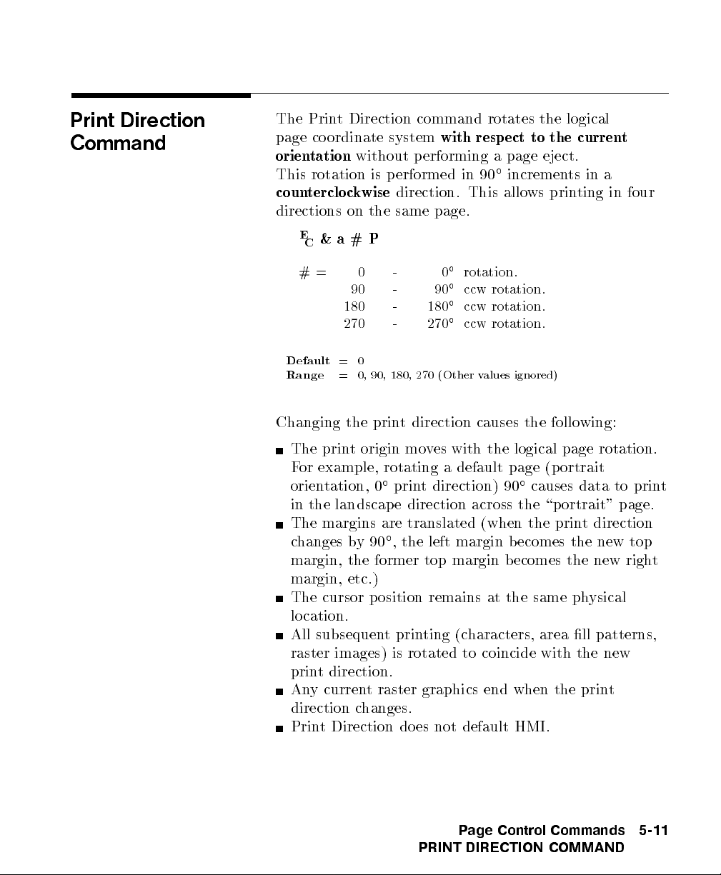
Print Direction
Command
The Print Direction command rotates the logical
page coordinate system
orientation
without performing a page eject.
with respect to the current
This rotation is performed in 90increments in a
counterclockwise
direction. This allows printing in four
directions on the same page.
E
&a#P
C
#= 0 - 0rotation.
90 - 90ccw rotation.
180 - 180ccw rotation.
270 - 270ccw rotation.
Default
Range
= 0
= 0, 90, 180, 270 (Other values ignored)
Changing the print direction causes the following:
The print origin moves with the logical page rotation.
For example, rotating a default page (portrait
orientation, 0print direction) 90causes data to print
in the landscap e direction across the \portrait" page.
The margins are translated (when the print direction
changes by90,the left margin b ecomes the new top
margin, the former top margin becomes the new right
margin, etc.)
The cursor position remains at the same physical
location.
All subsequent printing (characters, area ll patterns,
raster images) is rotated to coincide with the new
print direction.
Any current raster graphics end when the print
direction changes.
Print Direction does not default HMI.
Page Control Commands
PRINT DIRECTION COMMAND
5-11
Page 90

Note
The Print Direction Command does
vector graphic images. HP-GL/2 graphics can be rotated
only with the Orientation command (
HP-GL/2 \RO" command.
not
aect HP-GL/2
E
&`#O
C
) or the
5-12 Page Control Commands
PRINT DIRECTION COMMAND
Figure 5-3. Changing Print Direction on a Page
Page 91

Text Area
Text printing may be restricted to a sp ecic area within
the logical page using the Left Margin, Right Margin,
Top Margin, Text Length, and Perforation Skip Mode
commands. This area is known as the text area.
The left margin denes the distance b etween the left
edge of the logical page and the left edge of the text
area. The right margin denes the distance between the
left edge of the logical page and the right edge of the
text area. The width of the text area is the distance
between the left and right margins. The top margin
denes the distance b etween the top of the logical page
and the top of the text area. The text length denes the
length of the text area which in eect denes the bottom
margin. The perforation region is the distance from the
bottom of the text area to the top of the text area (top
margin) on the next page. The text area is shown in
Figure 5-4.
In general, characters are printed when they fall within
the text area. However, characters can be printed
between the b ottom of the text area and the top of the
text area on the next page only if perforation skip is
disabled. Characters are printed outside the text area
if a cursor move escape sequence p ositions the cursor
outside the text area (but within the printable area).
Characters that fall on (or outside) a margin as a result
of printing a character string, are clipped (not printed).
Notes
Attempting to printcharacters across a margin results
in the characters b eing discarded.
The default text area and the default HP-GL/2 picture
frame are the same.
Page Control Commands
5-13
TEXT AREA
Page 92

5-14 Page Control Commands
TEXT AREA
Figure 5-4. Text Area Within the Page
Page 93

Left Margin
Command
The Left Margin command sets the left margin to the
left edge of the specied column.
E
&a#L
C
# = Column number
Example
Default
Range
The rst column within a line is column 0, whichis
located at the left edge of the logical page (the HMI
setting denes the distance between columns, which
thereby denes the maximum number of columns on the
logical page). If the value eld sp ecies a column greater
than the current right margin, the command is ignored.
Margins representaphysical position and once set do
not change with subsequentchanges in HMI.
If the cursor is to the left of the new left margin, the
cursor is moved to the new left margin.
To set the left margin to column 5, send:
= Column 0 (Left b ound of logical page)
= 0 - Right margin
E
&a5L
C
Page Control Commands
LEFT MARGIN COMMAND
5-15
Page 94

Right Margin
Command
The Right Margin command sets the right margin to the
right edge of the specied column.
E
&a#M
C
# = Column number
Example
Default
Range
= Logical Page right bound
= Current left margin - Logical page right bound
The maximum right column is located at the right edge
of the logical page (the HMI setting denes the distance
between columns, which thereby denes the maximum
number of columns on the logical page). If the value eld
species a column which is greater than the right edge of
the logical page, the right margin is set to the right edge
of the logical page. If the value eld sp ecies a column
less than the left margin, the command is ignored.
Margins representaphysical position and once set do
not change with subsequentchanges in HMI.
If the cursor position is to the right of the new right
margin, the cursor is moved to the new right margin.
To set the right margin to column 45, send:
E
&a45M
C
5-16 Page Control Commands
RIGHT MARGIN COMMAND
Page 95

Clear Horizontal
Margins Command
The Clear Horizontal Margins command resets the left
and right margins. The left margin is set to the left edge
of the logical page (column 0) and the right margin is set
to the right edge of the logical page.
E
9
C
Page Control Commands
CLEAR HORIZONTAL MARGINS COMMAND
5-17
Page 96

Top Margin
Command
The Top Margin command designates the number of
lines between the top of the logical page and the top of
the text area.
E
&`#E
C
# = Number of lines
Default
Range
1
If logical page length is
1
=
inch down from top of logical page
2
= 0 - Length of logical page (Other values ignored)
of logical page.
1
<
inch, then the top margin is set to top
2
1
The Top Margin command is ignored if the value eld
(#) is greater than the current logical page length or if
the current VMI is 0 (VMI denes the distance b etween
lines of text).
Receipt of a Top Margin command resets the text length
according to the following equation:
The top margin represents a physical p osition and once
set does not change with subsequentchanges in VMI or
line spacing.
The vertical cursor p osition for the rst line of printis
determined by the currentvalues of the top margin and
VMI using the following equation:
5-18 Page Control Commands
TOP MARGIN COMMAND
Page 97

Note
The default cursor position is not lo cated at the
intersection of the top margin and the left bound of the
logical page (refer to Figure 5-5). The cursor is actually
positioned down 75% of the VMI distance (0.752VMI)
from the top margin. This positions the cursor at the
relative base line p osition of a character cell for correct
character positioning.
Example
Note
To set the top margin to line 4, send:
E
&`4E
C
The rst line of the logical page is line 0.
Figure 5-5. Margin Cursor Positioning
Page Control Commands
TOP MARGIN COMMAND
5-19
Page 98

Text Length
Command
The Text Length command designates the number of
lines (at a given VMI) within the logical page available
for printing text, the text area. This eectively denes
the bottom margin.
E
&`# F
C
# = Number of lines
Note
Default
Range
1
Maximum text length = INT(logical page length - top margin).
1
=
inch less than maximum text length
2
= Logical page length minus top margin
However, if the max text length is less than
is set to the maximum allowable.
1
1
inch, the text length
2
The value eld (#) sets the text length in lines
referenced from the top margin. If a value greater than
the logical page length minus the top margin is sp ecied
or if the current VMI is 0, the command is ignored.
The user default text length is invoked whenever the
orientation, page length, page size, or top margin is
changed. The user default text length is computed as
follows:
The user default VMI is selectable using the con
trol
panel; VMI is calculated from the FORM menu setting.
Example
5-20 Page Control Commands
TEXT LENGTH COMMAND
To select a text length of 60 lines, send:
E
&`6;F
C
Page 99

Perforation Skip
Command
The perforation region is the distance from the bottom
of the text area of one page to the top of the text area
(top margin) of the next page. When perforation skip
is enabled, a Line Feed or Half-Line Feed, whichwould
move the cursor beyond the bottom of the text area,
causes the cursor to move to the top of the text area on
the next page. When perforation skip is disabled, a Line
Feed or Half-Line Feed allows the cursor to move to the
next line or half-line in the p erforation region, allo wing
printing to continue there.
E
&`#L
C
#= 0-Disable
1 - Enable
Note
Default
Range
= 1
= 0-1 (Other values ignored)
Whenever the perforation skip mode is changed, the top
margin and page length are returned to their default
values.
When perforation skip is disabled, some print lines can
fall outside the printable area and be lost. If lines of
data could fall into the unprintable area, perforation skip
should be enabled.
Page Control Commands
5-21
PERFORATION SKIP COMMAND
Page 100

Horizontal Motion
Index (HMI)
Command
The Horizontal Motion Index (HMI) command
designates the width of the columns.
E
& k#H
C
# = Number of
1
inch increments.
120
Note
Default
Range
= Determined by the pitch value in the default font header.
= 0 - 32767 (valid to four decimal places)
The value eld is valid to 4 decimal places. A value of
zero (0) indicates no horizontal motion.
When xed pitch fonts are selected, all printable
characters including the Space and Backspace characters
are aected by HMI. When prop ortional fonts are
selected, the HMI aects only the Space control co de
character.
HMI is reset to match the new font when any of the font
characteristics are changed and when switching between
primary and secondary fonts with Shift In and Shift Out.
HMI is equal to the pitchvalue in the font
header. The factory default font's HMI is 12
12
(
120
1
=
inch per character, or 10 characters per inch).
10
When HMI is not sp ecically set using the HMI
command, PCL cursor moves are rounded to the nearest
full increment determined by the current unit of measure
setting. For example, if the unit of measure is set to 96
(one PCL Unit =
the nearest
96
1
(one PCL Unit =
nearest
1
300
inch.
1
inch), then the HMI is rounded to
96
inch. If the unit of measure is set to 300
1
inch), the HMI is rounded to the
300
5-22 Page Control Commands
HORIZONTAL MOTION INDEX (HMI) COMMAND
 Loading...