

Page 1

PCL 5
Color Technical Reference
Manual
Edition 1
E00994
5961-0635
Printed in U.S.A. 9/94
Page 2

Notice
The information contain ed in thi s documen t is subject to change witho ut n otic e.
HEWLETT-PACKARD MAKE S NO WARRANTY OF ANY KIND WITH REGARD T O
THIS MA T ERIAL, INCLUD ING , BUT NOT LIMIT ED TO, TH E IMPL IED WARRANTIES
OF MERCHANTABILITY AND FIT NESS FOR A PARTICULAR P URPOSE. HewlettPackard shall not be liable for er rors co ntain ed herein or for incide ntal c on seque ntial d amages in connection with the fur nish in g, per for man ce, or use of this material.
This document con tains pr opr ietar y inf or mation whic h is protec ted by copy rig ht. All righ t s
are reserved. No part of th i s documen t may be photoc opied, reproduc ed, or translated w ithout the prior written consent of Hewlett-Packard Company.
Copyright © 1994 by HEWLETT-PACKARD CO.
Adobe, PostScript, and the PostScript logo are trademarks of Ado be Systems Inco rp orated
which may be registered in certain jurisdictions. AppleTalk is a registered trademark of
Apple Computer, Inc. PCL and Resolution Enhancement are registered tr ademar ks of
Hewlett-Pac kar d Company. IBM is a registered trademark of International Business
Machines Corporation.
First Edition — Septembe r 1994
iiii
Page 3

Inside This Manual
What You Can
Learn
From This Manual
Note All commands describe d in this manual are not nece ssarily
Manual
Organization
This manual describes the PCL 5 commands used to
print color on the HP Color LaserJe t and Desk Jet 1200C
printers. Some of the main topic s include an overview of
the color printing process, using palettes, choosing color
modes, adjusting outpu t color to meet your requir eme nts,
printing color raster graph ics, and HP-GL /2 ve cto r
graphics. Ex amples are prov ided which demon str ate
the use of the PCL 5 color commands.
supported by both printe rs. See the PCL 5 Comparison
Guide for feature support inf ormation for eac h prin ter.
This manual is written primarily for users that are already
familiar with PCL 5 printe r featur es. For infor mation on
using PCL 5, see the PCL 5 Printer Language Technical
Reference Manual.
This manual contain s seve n chapter s. A brief description of
each chapter is prov ided below.
Chapter 1. C olo r Pr in ting Ov er vie w
This chapter explains back gro und in for mation about prin ting color docume nts usin g PCL 5. Topics include palettes,
device-d epen de nt v s. device -in depe ndent color, color selection, pixel encodin g, color modes, and c olor matchin g.
Chapter 2. Us in g Co lo r Mo des
Chapter 2 defines th e four color modes and desc r ibes how to
use them, including descrip tion s of sen ding color raster
data using different pixel encoding modes and color spaces.
iiiiii
Page 4

Chapter 3. Us ing Pal ett es
This chapter descr ibes the palettes associated with the four
color modes and explains how palettes are created, saved,
and modified.
Chapter 4. Modifying Output Color
This chapter explains ho w color can be optimized by co mpensating for differe nt con dition s, such as variation s in
color due to light sou rces, limitations of the orig inal ar twork and variation s in viewin g monitor s. Th e chapter
details the use of halftone rendering algorithms, color
lookup tables, gamma correction , and viewing illumin an t
commands provide d so that user s can requ est and rece ive
colored outpu t that match es the ir expec tation s.
Chapter 5. The PCL Print Model
Chapter 5 describes the pr int mode l and how it deter min es
the printed outcome w he n vario us patter ns, colo rs, and images are applied together on a page. This chapter di scus ses
the role that logical operation s and transparenc y mode s
have on this process.
Chapter 6. Ra ste r Gr ap hi cs
This chapter descr ibes the raster graph ics co mmand s and
also compressing raster graphics images using various compression methods.
iviv
Chapter 7. C olo r Vector Graphi cs (H P-G L/2 )
This chapter di scu s ses pr in ting color pag es using HP-GL/ 2,
the vector graphic s lan guag e inclu de d on all PCL 5 printers. The chapter desc ribes new and/or mod ified HP-GL/2
commands and how they are used to prin t with HP color
printer s.
Index
This manual includes an index for quick access to PCL command information.
Page 5

Related
Documents
The following documents provide related information about
Hewlett-Pac kar d PCL 5 prin ter s.
PCL 5 Printer La ngua ge Technical Reference Ma nual
The PCL 5 Printer Language T echnical Reference Manual
provides a description of the printer comman d langu ag e
that controls PCL 5 prin ter s. Th e manual pr ov ides explanations of each PCL command, and examples demonstrating
how the commands are used to manipulate the printe r.
A lar ge portio n of th e manu al is devoted to HP-G L/2, the
vector- b ased graph ics language in PCL 5 prin ter s.
PCL 5 Comparison Guide
This document provides printer-specific information on
paper handling, internal fonts, PCL command support, and
control panel in for mation . It identifies featu r e differ en ce s
between the var ious PCL 5 printer s, and how the printers
implement the commands describe d in the PCL 5 Printer
Language Technical Refe re nc e Manual .
Printer Job Langua ge Technical Referen ce Manu al
This manual describes PJL, the HP printer job language
used on many of the Hewlett-Pack ar d prin ter s. PJL is used
for switching pr inter languages, r equ esting status information, changin g display messag es, in quir in g about featu r e
settings, and other job-level functions.
PCL/PJL Technical Quick Re fere nce Gui de
This booklet is designed to prov ide quic k acce ss to the syntax of each PCL and PJL command. The commands are
grouped by their func tion so that those familiar with PCL
and/or PJL can fin d the syntax of a specific command w ithout opening the manual.
vv
Page 6

ContentsContents
1. Color Printing Overview
Color Concept s. . . . . . . . . . . . . . . . . . . . . . . . . . . . . . . . . 1-3
Palettes . . . . . . . . . . . . . . . . . . . . . . . . . . . . . . . . . . . . 1-3
Raster Mode . . . . . . . . . . . . . . . . . . . . . . . . . . . . . . . . 1-3
Raster Color vs. Non-Raster Color . . . . . . . . . . . . . . 1- 3
Device-D epen de nt vs. Devic e-I nd epen de nt Color. . . 1-3
Black and White Reference s . . . . . . . . . . . . . . . . . . . 1-4
Color Selection . . . . . . . . . . . . . . . . . . . . . . . . . . . . . . 1-5
Pixe l En c o ding . . . . . . . . . . . . . . . . . . . . . . . . . . . . . . 1 -5
Color Modes . . . . . . . . . . . . . . . . . . . . . . . . . . . . . . . . 1-7
Device-Ind epen de nt Color . . . . . . . . . . . . . . . . . . . . . . . 1- 9
Device-D epen de nt Color. . . . . . . . . . . . . . . . . . . . . . . 1- 9
Dev ic e-In d e pen de n t Color . . . . . . . . . . . . . . . . . . . . . 1 - 9
Color Matchin g. . . . . . . . . . . . . . . . . . . . . . . . . . . . . 1- 1 0
Processing Color Documen t s. . . . . . . . . . . . . . . . . . . . . 1-12
Non-Raster Color vs. Raster Color . . . . . . . . . . . . . 1-12
Color Processing Func tion s . . . . . . . . . . . . . . . . . . . 1 - 13
2. Usi n g C ol o r Mo des
Black-and- Wh ite Mod e (Defau lt) . . . . . . . . . . . . . . . . . . 2-1
Simple Color Mode. . . . . . . . . . . . . . . . . . . . . . . . . . . . . . 2-1
PCL Imaging Mode . . . . . . . . . . . . . . . . . . . . . . . . . . . . . 2-2
HP-GL/2 Imagin g Mode. . . . . . . . . . . . . . . . . . . . . . . . . . 2-2
Simple Color Mode. . . . . . . . . . . . . . . . . . . . . . . . . . . . . . 2-3
Contents-1Contents-1
Page 7

Simple Color Command. . . . . . . . . . . . . . . . . . . . . . . 2-3
PCL Imaging Mode. . . . . . . . . . . . . . . . . . . . . . . . . . . . . 2-5
Configure Image Data (CID) Command. . . . . . . . . . 2-5
Common 6-Byte Header . . . . . . . . . . . . . . . . . . . . . . 2-6
Short Form of CID Command . . . . . . . . . . . . . . . . 2-15
Long Form of CID Command . . . . . . . . . . . . . . . . . 2-17
Examples Using the CID Command. . . . . . . . . . . . 2-25
HP-GL/2 Imagin g Mode . . . . . . . . . . . . . . . . . . . . . . . . 2-28
3. Usin g Pa l ette s
Saving the Palette. . . . . . . . . . . . . . . . . . . . . . . . . . . . . . 3-3
Push/Pop Palette Command . . . . . . . . . . . . . . . . . . . 3-3
Palette Managemen t by ID. . . . . . . . . . . . . . . . . . . . . . . 3-5
Select Palette Command . . . . . . . . . . . . . . . . . . . . . . 3-7
Palette Control ID. . . . . . . . . . . . . . . . . . . . . . . . . . . . . . 3-8
Palette Control . . . . . . . . . . . . . . . . . . . . . . . . . . . . . . . . 3-9
Simple Color Palettes . . . . . . . . . . . . . . . . . . . . . . . . . . 3-1 1
Contents-2Contents-2
CID Color Palettes . . . . . . . . . . . . . . . . . . . . . . . . . . . . 3-13
HP-GL/2 Palettes . . . . . . . . . . . . . . . . . . . . . . . . . . . . . 3-15
Foreground Co l o r . . . . . . . . . . . . . . . . . . . . . . . . . . . . . 3-17
Foreground Color Command. . . . . . . . . . . . . . . . . . 3-17
Programming Color Palettes . . . . . . . . . . . . . . . . . . . . 3-19
Color Component One . . . . . . . . . . . . . . . . . . . . . . . 3-19
Color Component Two . . . . . . . . . . . . . . . . . . . . . . . 3-20
Color Component Th ree. . . . . . . . . . . . . . . . . . . . . . 3-20
Assign Co l o r In d ex. . . . . . . . . . . . . . . . . . . . . . . . . . 3-2 1
Page 8

4. Mo di fyi n g Ou tpu t Co l or
Halftone Ren der Algo rith m s. . . . . . . . . . . . . . . . . . . . . . 4-2
Render Alg or ithm Comman d. . . . . . . . . . . . . . . . . . . 4- 2
User-Defin ed D ithe rs. . . . . . . . . . . . . . . . . . . . . . . . . 4-5
Download Dith er Matr ix Command . . . . . . . . . . . . . 4-6
Multiple Dither Matric e s. . . . . . . . . . . . . . . . . . . . . . 4- 9
Example . . . . . . . . . . . . . . . . . . . . . . . . . . . . . . . . . . 4-10
Color Lookup Tables . . . . . . . . . . . . . . . . . . . . . . . . . . . 4-1 1
Gamma Correction . . . . . . . . . . . . . . . . . . . . . . . . . . . . 4-15
View in g Illumin ant . . . . . . . . . . . . . . . . . . . . . . . . . . . . 4-16
Mon ochro m e Printing . . . . . . . . . . . . . . . . . . . . . . . . . . 4-18
Driver Configuration Comman d. . . . . . . . . . . . . . . . . . 4- 19
5. The PCL Print Model
Command Sequence. . . . . . . . . . . . . . . . . . . . . . . . . . . . . 5-6
Source T r an spare nc y Mod e Command. . . . . . . . . . . . . . 5-7
Pattern Transpar en cy Mode Comman d . . . . . . . . . . . . . 5-8
Logical Operatio ns. . . . . . . . . . . . . . . . . . . . . . . . . . . . . . 5-9
Logical Operations and Transparency Interactions 5-12
Logical Operation Command . . . . . . . . . . . . . . . . . . . . 5-13
T able of Logical Ope ratio ns . . . . . . . . . . . . . . . . . . . 5-1 5
Pixel Placemen t. . . . . . . . . . . . . . . . . . . . . . . . . . . . . . . 5-21
Pixel Placemen t Command . . . . . . . . . . . . . . . . . . . 5-24
Filling with Patterns. . . . . . . . . . . . . . . . . . . . . . . . . . . 5-2 5
Pattern ID (Area Fill ID) Command. . . . . . . . . . . . . . . 5-26
Select Current Pattern Comman d . . . . . . . . . . . . . . . . 5-30
User-Defin ed Patter n Graph ic s . . . . . . . . . . . . . . . . . . 5-31
Download Pattern Comman d . . . . . . . . . . . . . . . . . . . . 5-36
Contents-3Contents-3
Page 9

Set Pattern Reference Point Comman d. . . . . . . . . . . . 5-42
Pattern Control Comman d. . . . . . . . . . . . . . . . . . . . . . 5-43
Rectangular Area Fills (Rules). . . . . . . . . . . . . . . . . . . 5-44
Pattern Tran spare nc y for Rec tan g ular Ar ea Fill. . . . . 5-49
Rectangular Fill Examples. . . . . . . . . . . . . . . . . . . . . . 5-51
6. Raster Graphics
Raster Graphics Command Sequen c e . . . . . . . . . . . . . . 6-5
Raster Graphics Resolution Command . . . . . . . . . . . . . 6-7
Raster Graphics Presen tation Mode Command . . . . . . 6-9
Source Raster Height Command . . . . . . . . . . . . . . . . . 6-12
Source Raster Width Comman d. . . . . . . . . . . . . . . . . . 6-15
Start Raster Graphics Command. . . . . . . . . . . . . . . . . 6-17
Raster Y Offset Command . . . . . . . . . . . . . . . . . . . . . . 6-19
Set Compression Method Command . . . . . . . . . . . . . . 6-20
Unencoded (Method 0). . . . . . . . . . . . . . . . . . . . . . . 6-20
Run-length En cod in g (Method 1 ) . . . . . . . . . . . . . . 6-2 1
Contents-4Contents-4
Tagged Image File Format Encoding (Method 2). . 6-21
Delta Row Compression (Metho d 3) . . . . . . . . . . . . 6-25
Adaptive Compression (Metho d 5) . . . . . . . . . . . . . 6-30
T ran sfer Raster Data Command s . . . . . . . . . . . . . . . . 6-35
End Raster Graphics Command. . . . . . . . . . . . . . . . . . 6-39
Raster Scaling. . . . . . . . . . . . . . . . . . . . . . . . . . . . . . . . 6-40
Destination Raster Width . . . . . . . . . . . . . . . . . . . . 6-41
Destination Raster Height . . . . . . . . . . . . . . . . . . . 6-41
Scale Algo rith m . . . . . . . . . . . . . . . . . . . . . . . . . . . . 6-42
Raster Graphics Example. . . . . . . . . . . . . . . . . . . . . . . 6-43
Color Raster Graphics Example. . . . . . . . . . . . . . . . . . 6-46
Page 10

7. Color V e cto r Gr ap hics (HP-G L/2)
Ent er HP-GL/ 2 M o de. . . . . . . . . . . . . . . . . . . . . . . . . . . . 7 -2
Default Settings when Enter in g HP-G L/2 . . . . . . . . 7-4
MC (Me rge C ontrol). . . . . . . . . . . . . . . . . . . . . . . . . . . . . 7- 6
PC (Pen Color) . . . . . . . . . . . . . . . . . . . . . . . . . . . . . . . . 7-14
NP (Number of Pens). . . . . . . . . . . . . . . . . . . . . . . . . . . 7-16
CR (Color Range). . . . . . . . . . . . . . . . . . . . . . . . . . . . . . 7- 1 8
PP (Pixel Placemen t ). . . . . . . . . . . . . . . . . . . . . . . . . . . 7- 19
Index
Contents-5Contents-5
Page 11

1
Color Printin g Ove r viewColor Printin g Ove r view
Introduction This chapter provides an overview of the way color i s used
in the HP Color LaserJe t and De skJet 1200C prin ter s. I t
previews the remainin g chapter s, w hic h descr ibe th e
specific details of Hewlett-Packard color printing.
Note The features described in this docu men t are a superset of
those supported by the Color LaserJet and DeskJet 1200C
printers. Some features are supported on one or the other
printer s, but not on both . See the PCL 5 Compar is on Guid e
for specific feature sup port for each printer.
Processing a color document inv olves specifyin g a palette or
palettes, and then using the colors within the current
palette to print. For non- r aste r prin ting , items such as
text, rule s, an d v ec tors are simply printed in the curren tly
active color, which is specified using the For egr ou nd Color
command or Select Pen command if in HP- GL /2. For ra ster
printing, the color of each pixel is specified as either a
direct color specific ation , or as an index into the palette,
depending on the pixel en co din g mode.
The PCL Print Model deter min es how color is applied to the
page. The printed re sult can vary in backgro und an d
texture depending on the source transparency mode,
pattern transparency mode, and selected logical operation
(ROP). Besides the pr e-de fin ed shadin g and pattern s, user s
can define new mono chr ome or multicolor patterns.
When printing color pages, a user can choose one of several
color modes, depen din g on the desired r esults. Each color
mode has a palette associated with it. Simple Color Mo de
Page 12

provides a palette of fully satur ated color s wh ose colo rs are
similar to those of a plotter’s pen colors. The palette is
nonprogrammable, and is intended for simple printing of
items such as bar and pie charts. For application s requ ir ing
different or mor e specif ic c olor s, the printer offers the PCL
Imaging and HP-GL/2 Imaging Mo des. The palette c olor s
in these two modes can be modified to pro vid e the desir ed
result.
When choosing color for a particular application, the
Color LaserJet prin ter provides device-dependent and
device-independent color (the DeskJet 1200C supports
only device-dependent color). Device-independent color
provides accurate colo r matc hing based on an absolute color
standard. It is preferred w he n users wan t a prec ise co lor to
match the output from ano the r devic e or to match the colo r
on an existing page.
Besides providing devic e-in de pen den t co lor for prec ise colo r
matching, the HP prin ter s can modify color to compen sate
for various characteristics. The Color LaserJet printer
supports the followin g method s of modifying color (the
DeskJet 1200C printer supp or t s halfton e algorithms and
gamma correction , but not colo r looku p tables or the
View in g Illumin ant c omman d).
Halftone render algorithms determine how colors are
rendered using the printers available colors. Halftone
algorithm s can be used to chang e apparen t resolu tion ,
change the textu re of image s, reduc e the number of
colors, and ch an ge a color image to mono chr ome.
Color lookup tables can remap colors to compensate for
various diff er en ce s in inpu t data, suc h as un w anted color
casts caused by unbalanced photographic light sources.
Gamma correction provides a way to adjust for color
differenc es in display monitors so that the display mor e
closely matches the prin ted ou tpu t.
Since the appearance of colors changes under different
viewing light sources, the Viewing Illuminant command
allows the application to modify outp ut color based on
the light sourc e used to view the pr inte d page .
1-2 Color Printing Overview1-2 Color Printing Overview
Page 13

Color Conc epts This section describes so me of the conce pts and ter mino log y
used in this chapter, such as palettes, raster vs. non-raster
color, device-independent vs. device-dependent color, black
and white refer en ces, co lor selection , pixel en codin g , and
color modes.
Palettes A palette is a collection of colors that ar e sele cte d by their
index numbers. You can create yo ur ow n palette or choose
from one of several fixed palettes. Although only one p alette
is active at any time, all palettes are assigned ID numbers
and can be stored in the pr inte r for later selection usin g the
ID number. They can be deleted when desire d. Palettes can
also be saved (pushed) to a stack and later retriev ed
(popped) when needed.
Raster Mode Raster mode is entered explic itly by the Start Ra ster
command (?*r#A) or implicitly by a Transfe r Raster
command (?*b#V, ?*b#W). Raster mode is exited explicitly
by an End Raster command (?*rC) or implicitly by a
non-raster command.
Raster Color vs.
Non-Raster Color
Device-Dependent
vs. Device-
Independent Color
Palettes are used differently dep en din g on wheth er the
printer is in raster mode.
In non-raster mode, the palette is alway s used for color
selection. The color of text or patter ns is specified using
the Foregrou nd Color comman d ( ?*v#S).
In raster mode, the palette is only used for index ed color
selection; it i s not used for direct color selection. (Indexed
and direct color selection are explain ed later in this
section.)
Device-dependent color spaces are relative to the dev ice ’ s
ability to produce spec ific colors. For example, if red is
specified in a devic e-d epen de nt color space, two differ en t
printers will combin e the same amounts of cyan , mag enta,
yellow, and black toner to produce the color, but the results
Color Printing Overview 1-3Color Printing Overview 1-3
Page 14
will be different because of the different properties of the
toner.
Device-independent color is specified absolutely, in a color
coordinate system that is indep en dent of any device . For
example, if red is specified in a device- ind epen de nt color
space, two printers will alway s p rodu ce the same result,
even though they may need to combine different amounts of
cyan, magenta, y ellow, and black toner. Printer s that
produce devic e-in dep en den t colo r are calibr ated to prec i se
color standards.
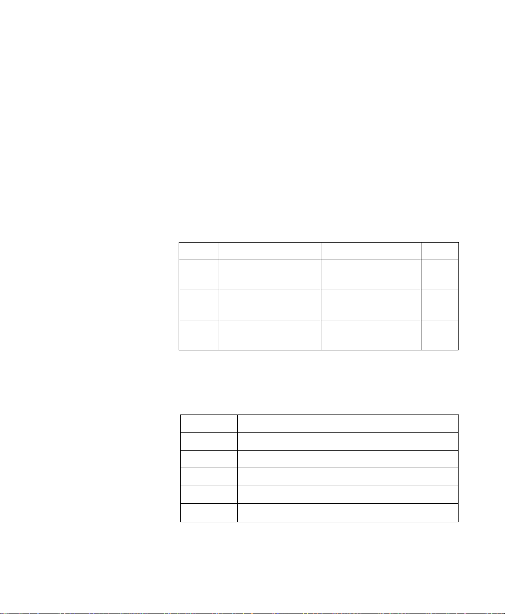
Black and White
References
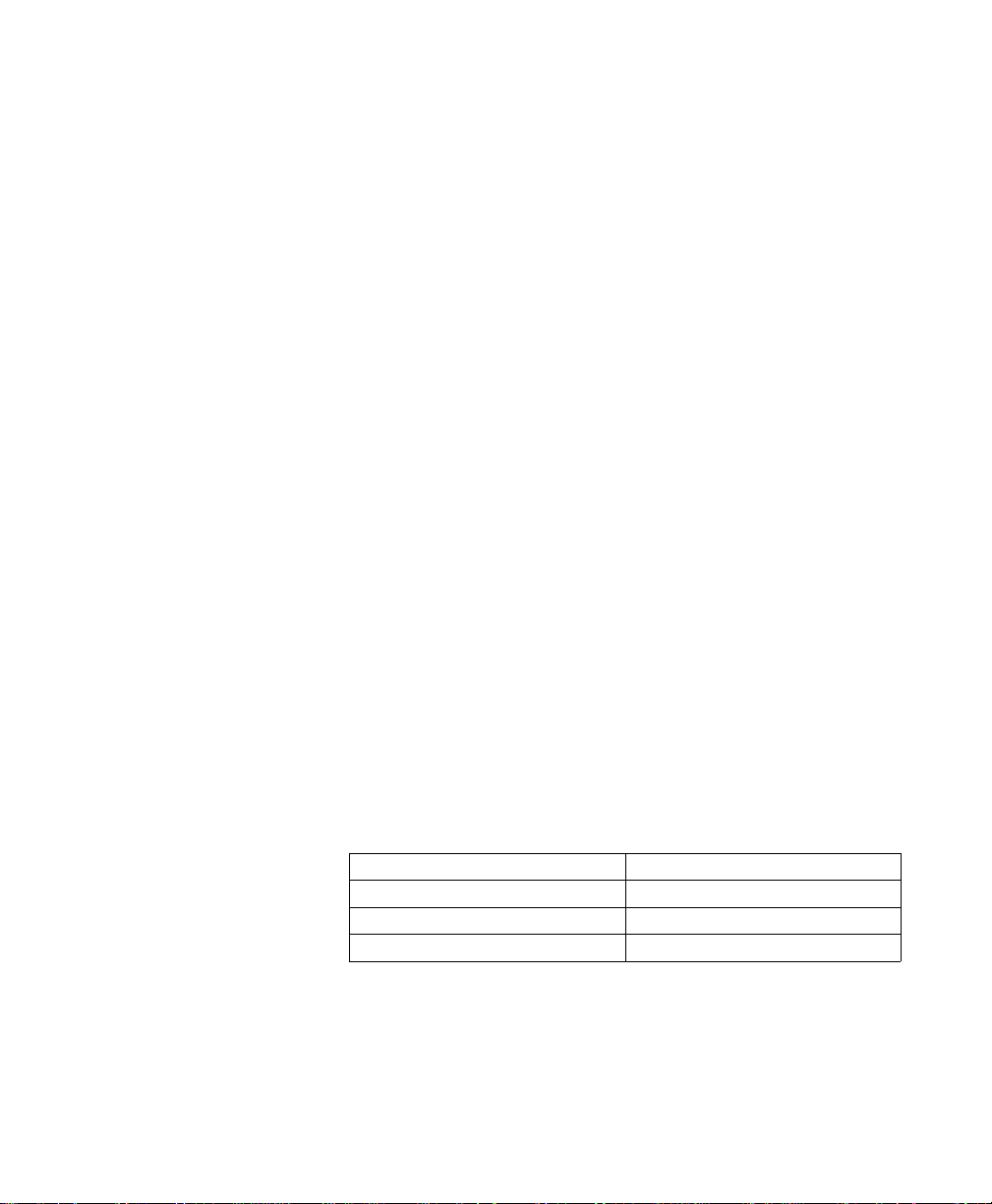
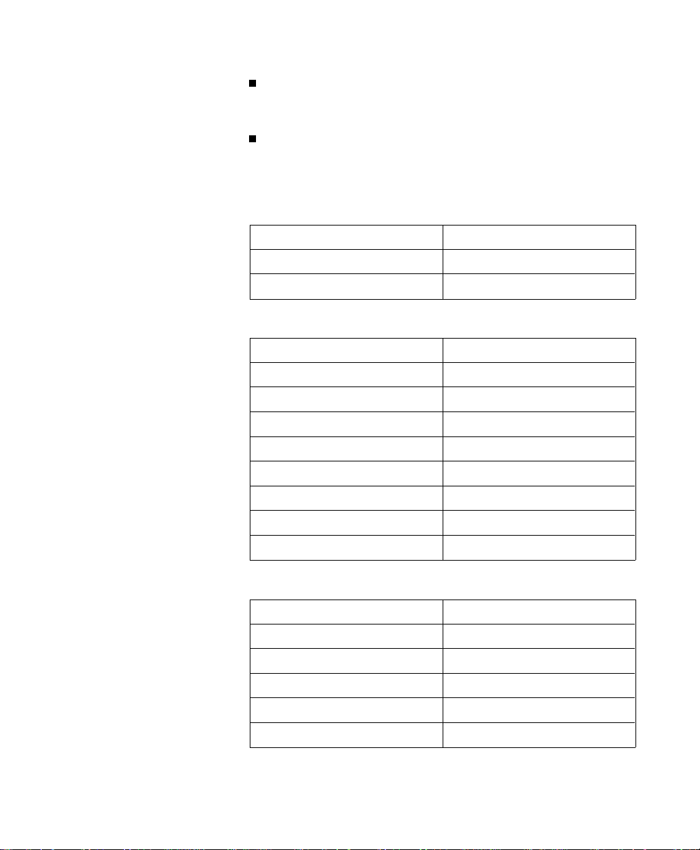
Example: Assuming the white and black refere nces are set as follows:
Device-dep endent color specific ation s are ba sed upon an
arbitrary range of values for each primary color component.
The range endpoints f or each color compon en t are called
black and white references for that c omponent. Colors
relative to these predef ine d limits are derived by specif ying
the amount of each compon en t.
For the Device RGB color space, the maximum limit is
called the white refer ence and the minimu m limit is called
the black reference. Regardless of the number chosen, the
white referenc e repr esen ts the maximu m valu e of a
primary color that a device c an produ c e, and the black
reference re pr esen ts the minimu m valu e of that primar y
color. For example, if 100 is chosen as the white reference
for red in the RGB color model, it represents the reddest
red the device can pr odu ce. If 10 were chosen instead, then
10 would represent the same red.
Scenario 1
White Reference Black Reference
red = 63 red = 0
green = 63 green = 0
blue = 63 blue = 0
1-4 Color Printing Overview1-4 Color Printing Overview
Page 15
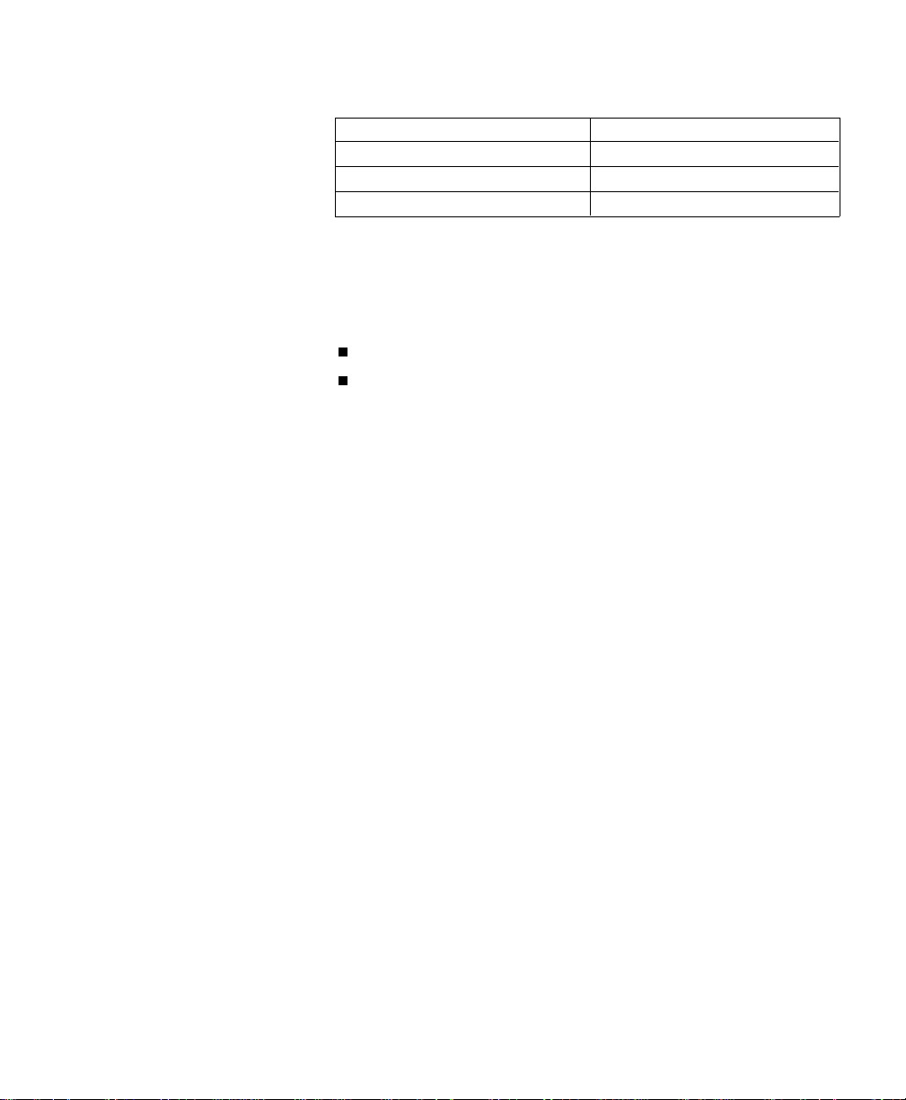
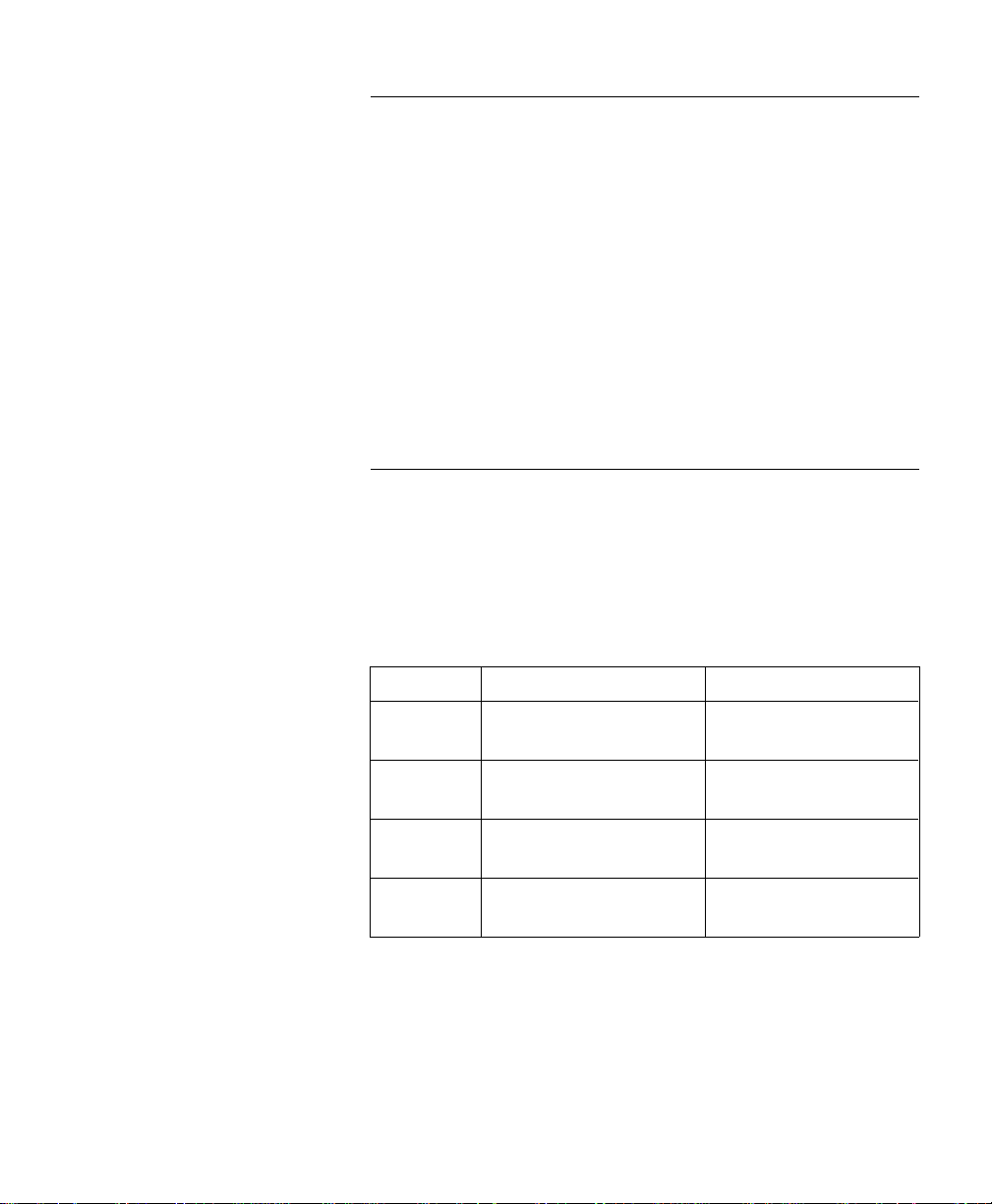
Scenario 2
White Reference Black Reference
red = 63 red = 4
green = 127 green = 0
blue = 31 blue = 0
Using these referen ce values, 50% blue for scenar io 1 is 31,
and 50% blue for scenario 2 is 15.
Color Selection The HP color printer s offer two methods for selecting colo rs:
Indexed selection
Direct selection
In indexed selection, colors are chosen using their palette
index numbers. For non-r aster mode, the palette index
number is specified using the Foregro und Color command .
In raster mode, the data bit combination for each pixel
forms an index nu mber. The example below shows how the
index numbers for an 8-colo r palette are specified:
Three-bit combinations: 0 1 0 1 0 1 0 1
0 0 1 1 0 0 1 1
0 0 0 0 1 1 1 1
Palette index number : 0 1 2 3 4 5 6 7
The number of colors in the palette dictates the numbe r of
bits per pixel of raster data required to sp ecify an index
number. For example, to specify 256 colors you need to send
8 bits of raster data per pixel (2
In direct selection , color s are spec ified u sing the propo rtio ns
of their primary compone nts. For example, using a
24-bit-per- pixel repr esen tation , the color specified by (0xf f,
0xf0, 0x00) for red, green , and blue would pr int a sligh tly
red-tinted yellow. A palette is not u sed for direc t se lec tion .
8
= 256).
Pixe l E nc o ding Colors are encoded in a row of raster data using either
plane or pixe l format. In planar format, all th e pixels in a
row are partially specified by one plane (bit) befo re the next
Color Printing Overview 1-5Color Printing Overview 1-5
Page 16
plane is sent. In pixel for mat, each pixe l is fully spec ified
before sending the next pixel.
Encoding by Plane
Planar encoding uses successive data planes, each
providing one bit for each pixel in a row. Each plane builds
upon the prec edin g plane s until th e pixe l s in a row are fully
defined. A pixel is not fully def ine d un til it has rec eiv ed a ll
the planes for that r ow.
The planes in a row form index number s that defin e a pixel
by selecting a palette entry. For example, an 8-entry palette
requires 3 plane s (2
3
= 8). The underlined bits below
compose the index of th e color of th e thir d pixel in the firs t
row .
?*b#V row 1 plane 1 (red) b1 b1
?*b#V plane 2 (grn) b2 b2
?*b#W plane 3 (blue) b3 b3
b1 b1 b1 b1 . . .
b2 b2 b2 b2 . . .
b3 b3 b3 b3 . . .
?*b#V row 2 plane 1 (red) b1 b1 b1 b1 b1 b1 . . .
Encoding by Pixel
When encoding by pixel, each pixel is fully specified before
any bits are sent for the next pixe l. For examp le, if fou r bits
are needed to define a pixe l, then ever y grou p of four bits in
the data stream defines a pixel. The under line d (c4 . . . c1)
group below define s the secon d pix el in the first ro w.
?*b#W row 1 b4 b3 b2 b1
c4 c3 c2 c1 . . .
?*b#W row 2 b4 b3 b2 b1 . . .
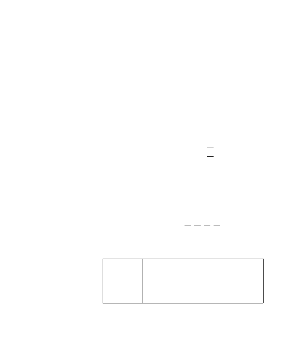
The table below shows the four PCL option s for selectin g
colors and encodin g color raster data.
1-6 Color Printing Overview1-6 Color Printing Overview
Indexed
Selection
Direct
Selection
Planar Encoding Pixel Enco ding
Indexed plan ar Inde xed pixe l
Direct planar Direct pixel
Page 17
Color Modes There are four PCL 5 color modes:
Black and White mode
Simple Color mode
PCL Imaging mode
HP-GL/2 Imagin g mode
All four modes create a palette. The palettes used in the
Black and White mode and Simple Color mode are not
modifiable. You can, however, modify the palettes in the
PCL Imaging and HP-G L/2 Imaging mod es.
You can use more than one mode on the same page. For
example, you could enter the Simple Color mode to print a
headline and a bar chart, PCL Imag in g mode to prin t a
raster photogr aph , and Black and Wh ite mode to prin t
some body text. Each mode i s described in more detail in
Chapter 2, “Using Color Modes.”
Device-Dependent
Color Spaces
The following PCL commands can alter color processing for
device-d epen de nt c olor spaces:
Renderin g Algorithm (?*t#J)
Gamma Correction (?*t#I)
Color Lookup Tables (?*l#W)
Configure Image Data (?*v#W)
Simple Color (?*r#U)
Mono chrome Print Mode (?&b#M)
Color lookup tables or gamma cor r ection (which are
mutually exclu sive) can modify the mapping of inp ut to
output.
Color Printing Overview 1-7Color Printing Overview 1-7
Page 18
Device-Independent
Color Spaces
The following PCL commands can alter color processing for
device-in de pen den t co lor spaces:
Renderin g Algorithm (?*t#J)
Gamma Correction (?*t#I)
Color Lookup Tables (?*l#W)
Configure Image Data (?*v#W)
View in g Illumin ant ( ?*i#W)
Mono chrome Print Mode (?&b#M)
Device-in dependent color spaces ar e supported under the
following conditions:
1. The Configure Imag e Data command (?*v#W) co nfigur es
the current palette and specifies a devic e-in de pen den t
color space.
2. The Render Algorithm comman d (?*t#J) is set to one of
the following:
Nearest Intensity ( ?*t0J)
Device Best (?*t3J, ?*t5J)
Error Diffusion (?*t4J, ?*t6J)
Cluster Order ed Dith er (?*t7J, ?*t8J)
Ordered Dith er (?*t1 1J, ?*t12J)
Color proces sing rever ts to de vice-dependen t pr oc essin g if
the render algor ithm is chang ed from one of the above. This
is because extensiv e devic e characterization is necessary to
achieve device- independenc e— calibration must be based on
known parameter s that aff ect the dev ic e’ s co lor gamut.
Render algorithms such as Snap to Primaries (?*t1J),
Snap Black to White and Colors to Black (?*t2J), or
User-Defin ed Half ton e ( ?*t9J) either limit the number of
colors available, or are undefin ed to the exte nt th at their
performan ce i s not as precise. These algor ith ms, the refore,
produce dev ic e-de pen den t re sults. D ev ice -in depe nd en t color
is again generated if the render algo rith m chan g es to one of
the 5 listed above and the color space has not chan ged.
1-8 Color Printing Overview1-8 Color Printing Overview
Page 19

DeviceIndependent
Color
The PCL language charac ter izes co lor as either devic e-d ependent or device -in depe nd en t. Both categor ies encomp a ss
many color spaces, each with unique characteristics.
Device-
Dependent
Color
Device-
Independent
Color
Device-dep endent color is relative to the devic e’s inhere nt
characteristics. For example, the colors produced by
plotters are relative to the color of the installed plotter
pens. Pen color varies consider ably, especially as pens wear
out, chang in g the color of th e outp ut. Likew ise, for monitor
screens, the red, g re en, and blue scr een ph osph or s
determine the colo rs produ c ed. Fully satu rated co lor s can
vary greatly betw een sc r een s. For p rin ter s, the color
produced on a page depend s on the prin ter’s subtrac tiv e
inks or toner (cyan, mag en ta, yellow, and black).
When using devic e-d epen de nt c olor, devices receiv ing
relative color specific ation s for the same color freque ntly do
not produce the same color. For example, a monitor’s
saturated red may be differen t than a plotter’s. In short,
the same color page may appear considerably different on
different devices.
The HP color printer s prov ide devic e- depe nd en t color
specified using either the Device RGB or CMY color spac es.
In contrast with device-dependent color, device-independent
color is based on an absolute color standar d—th e
tristimulus values of human vision. The device, whether a
printer or other wise, is calibrated to match an indep en dent
color specification. The color specification is translated in
such a way that the resultant colo r is indepen den t of the
device. Examples of color sp aces based on absolute
standards includ e Ko dak P hoto Y CC, CIE L *a*b*, YU V, and
the proposed YCr Cb. Eac h is a transfor m fr om tristimu lu s
CIE XYZ space.
With proper calibration , any dev ic e can provid e a transfo rm
from device-in dependent colo r spac e to the device’s ow n
color space, pro du cin g outp ut fr om diffe re nt dev ic es tha t
have the same color appear an c e. For example, if a monitor’s
Color Printing Overview 1-9Color Printing Overview 1-9
Page 20

parameters are known (gamma, gain , chromatic ity
coordinates for each primar y, and the white point), the
monitor’s RGB pixel information can be transformed into
device-in de pen den t co lor.
The Color LaserJe t prin ter pro vid es device- independe nt
color specified usin g either the CIE L*a*b*, Color imetr ic
RGB, or Luminan ce-Ch ro minan c e color spaces.
Color Matching When attempting to match color produced by differ ent
devices, it is importan t to know the differ en ce betwe en true
color matching and appearance matching.
Proper devic e calibr ation can ach iev e tr ue color match in g ,
so that a side-by-side comparison of a prin ted pag e with the
monitor on which the pag e was desig ned will show an exac t
match. However, true color matching is only satisfac tor y
when using the mon itor as a viewin g refer en ce. V iew ed
away from the screen , the prin ted pag e may appe ar flat and
unsaturated bec ause pr in ter s and monito rs hav e differ en t
dynamic ranges. For example, black on the scre en appear s
gray when compared to printed black, wh ich is
unacceptable if the intent i s pure black . Likewise, the white
produced on a monitor scr een appear s yellow or blue when
compared to a white sheet of paper. True colo r matching
would require that g ray be prin ted in the black area s and
colored dots be printed in the white areas.
1-10 Color Printing Overview1-10 Color Printing Overview
Color Appe arance Matching
Color appearance matching goes beyond true color
matching by inclu din g adju stmen ts for the dynamic range s
of the devices, so the user’s inten t is maintained . For
example, the white areas of a page shown on a monitor
display screen would be pr inte d as white on a printed pag e
because the user spec ified w hite , even thoug h the scr een
cannot duplic ate a wh ite that tru ly matc hes wh ite paper.
Although the prin ted color does not ex ac tly matc h scree n
color, color appearanc e does match , which is what use rs
usually want. To maximize user satisfaction, the PCL
language uses appearan c e match in g when ren der in g
device-in de pen den t co lor.
Page 21

Color Lookup Tables
Color lookup tables, which prov ide addition al co ntrol of th e
printed outpu t, are tran sfor mation s that map input data
into a new output color range based upon poin t-by -poin t
conversions.
Overhead tran sp are ncies pr ovide on e examp le of a good use
for color looku p tables. Let’s say a page is printed on plain
paper and it matches the user’s expectatio ns. When
printing the same documen t on ov er he ad tr ansparency film,
the resulting image looks unsaturated and flat. To
compensate, the user can se nd a color looku p table to
increase color satu ration with out ch angin g compositio n (for
example, using the CIE L*a*b* color space to increase the
a* and b* parameters in equal amoun ts).
Color lookup tables can al so be used to adjust data from a
Kodak CD-ROM , wh ich uses th e Photo Y CC dev ic eindependen t color sp ace . The gamma correction table is
complex and canno t be descr ibed by the traditio nal
logarithmic expr es sion. Howev er, since the data can be
mapped into new data values via tables, the user can
provide a gamma correction table that e ssentially desc ribe s
the complex correction factors.
Color lookup tables can be used to “ne utral-balan c e” an
image. For example, an underwater photog rap h produ c es a
severe bluish cast when printed. The user can eliminate
that cast from the image by providin g a color looku p table
that subtracts some color portion from each of the primaries.
Ill um i nation Mo d els
Illumination sources have different spectral distributions,
causing colors to appear differently under one light source
compared to anothe r. For example, printed colors that look
normal in natural sunlig h t shift in hue when viewed u nd er
fluorescen t and tun g sten ligh ting . The PCL langu ag e
allows the user to compen sate for th e differ enc es in vie win g
illumination using the V iew in g Illu min ant comman d. It
allows the user to select differ ent illu min ation s.
Color Printing Overview 1-11Color Printing Overview 1-11
Page 22

Processing Color
Documents
To process a color pag e, PCL prov ides way s of specify in g
and modifyin g color so that the printe d result ap pear s as
the user desires. This sectio n prov ides a conc eptu al
overview of the process.
Non-Raster Color
vs. Raster Color
All color portions of a page consist of eithe r:
Page Marking Primitives (non-raster data)
Color Raster Data
Page Marking Primitives
Non-raster data con si sts of HP-GL/2 and PCL pag e
marking primitiv es such as glyph s, rules, poly g on s, circ les,
and vectors. Pag e markin g primitiv es con tain no color
information about th e image. They merely mar k the pag e
with attributes as signed to the curren t wo rkin g
environme nt (for example, colo rs, patte rns, log ic al
operation modes, etc.). Page markin g primitives act a s
stencils throu g h which co lor “paint” is poured, forming a
homogeneous pattern.
Page marking primitiv es prin t in the curren tly specif ied
color, which is specified usin g the Foreg ro und Color
command. For ex ample, if y ou specify the color blue using
the Foreground Color co mmand , and then send some tex t to
the printer, the text will be printed blue.
Color Ra ster Da ta
Unlike page markin g primitives, eac h pixel of a colo r ra ster
image contains co lor information. A color raster pixel may
be defined by either:
Palette Entry Indices
Direct Color Spec ific ation s
User-def ine d color pattern s are a form of color raster, but
each pixel of a user -def ine d color pattern can be defined
only by palette entry indice s, not by direct co lor
specification s.
1-12 Color Printing Overview1-12 Color Printing Overview
Page 23

Color Processing
Functions
Given these two color uses, page mark in g primitiv es and
color raster data, color processin g must:
Convert color attributes to an internal re pr esentation
that can be poured through the page marking stencil
onto the destination via some logical oper ation .
Convert multiple-bit-per-pixel color raster to an internal
representation that c an be merge d into th e destinatio n
via some logical operation.
Color processing must have access to the following state
variables, which indic ate the for m and attribu tes by whic h
the two color groups are g ener ated.
Halftone (rendering algorithm)
RGB gamma correction
Device-dep endent color lookup tables for eac h of the
three primaries
Chapter 2 describes in more detail how color raste r data is
specified.
Color Printing Overview 1-13Color Printing Overview 1-13
Page 24
U sing Color M odesU sing Color M odes
Introduction The PCL printer lang uag e has fou r color modes:
Black-and- Wh ite
Simple Color
PCL Imaging
HP-GL/2 Imaging
PCL allows you to use any mode or combination of modes to
accomplish your printing objective s most effic ien tly.
All four of the color modes create a palette. The palette for
each mode is discussed in the section desc ribin g that mode,
and also in Chapter 3 (“Using Palettes”).
2
Black-and-White
Mode (Default)
Black-and- Wh ite Mod e is the defau lt colo r mode. PCL
devices power up in this mode and revert bac k to it
whenever the printer receives an ?E reset.
Black-and- Wh ite mo de i s also selectable using the Simple
Color command (?*r1U). This mode creates an
unmodifiable, default 2-pen palette, with white at index 0
and black at index 1 (compatible with ex isting mon ochr ome
PCL 5 printer s).
Simple Color Mode Simple Color Mode, entered by the Simple Color command
(?*r#U), creates a fixed-size, fixed- color, unmodifiable
palette. Dependin g on the value field, ?*r#U can create a
2-pen Black-and- Wh ite palette, an 8-pen RGB palette, or an
8-pen CMY palette. When using the Simple Color mode, the
pixel encoding mode is always indexed planar.
Page 25

PCL Imaging Mode PCL Imaging Mode, enabled by the Configure Image D a t a
command (?*v#W), allows a maximum of 24 bits per pixel
for color specific ation . Theref ore, mor e color s (prod uc ed by
halftoning) may be specifie d than are obtainable in Simple
Color Mode. In the PCL Imagin g M ode, p ixe l en c oding
mode, bits per pixel, bits per primary, white/black
references, and the color palette are all programmable .
HP-GL/2 Imaging
Mode
In HP-GL/2, the Initialize (IN) command starts color
imaging and perf or m s the following:
Sets the pixel encoding mode to ind ex by plane .
Sets bits per index to 3.
Creates an 8-pen palette that is reprogrammable in
either PCL or HP-G L/2 con tex t s (see Chapter 3, “Usin g
Palettes,” for more information ).
Although default HP- GL /2 palettes are differen t than
default PCL palettes, an HP-GL/ 2 palette is modifiable in
either PCL or HP-G L/ 2 (u sin g the Assig n Color Index
[?*v#I] or Pen Color [PC] commands, respectiv ely ).
Likewise, a PCL palette created by the Con figure Imag e
Data command (?*v#W) is modifiable in both PCL an d
HP-GL/2 using the same comman ds.
The active palette is always transferred between HP-GL/2
and PCL contex ts. Sinc e only one palette at a time can be
active, a new palette created in either contex t overwr ites
the current palette.
2-2 Using Color Modes2-2 Using Color Modes
Page 26

Simple Color
Mode
The Simple Color command (?*r#U) spec ifies colo r
selection from a fixed palette. RGB or CMY raster data
must be sent by plane (?*b#V) as well as by row (?*b#W).
The last plane in each row is sent using the ?*b#W
command; all other planes are sen t using the ?*b#V
command. In Simple Color mode, the pixel en c odin g mode
is always indexed planar.
Simple Color
Command
The Simple Color command creates a fixed-size palette,
whose color specification cannot be modified.
?*r#U
# = –3 – 3 planes, device CMY palette
1 – Single plane K (Black) palette
3 – 3 planes, device RG B palette
Default = 1
Range = –3, 1, 3
The absolute value of the value field specif ies the number of
planes per row of raster data to be sent. The number of
entries in the new palette is 2
1. For example, a 3-plane palette has 8 entries, with index
numbers 0 to 7.
This command destroys the activ e palette and creates a
new palette, which beco mes the active palette . When the
Simple Color mode is active, PCL and HP -G L/2 comman d s
that modify the palette are locked out (NP, PC, ?*v#A,
?*v#B, ?*v#C, ?*v#I). When a Simple Color palette is
popped from the stack ( ?*p#P), it cannot be modified, and
the pixel encoding mode reverts to indexed planar.
A value field of 1 creates a 2-entry Black-and-White
default palette.
n
, with index values 0 to 2n –
Usi ng Color Modes 2 -3Usi ng Color Modes 2 -3
Page 27
A value field of 3 creates an 8-entry Device RGB palette
(compatible with a PCL Imaging Mode palette, but not
an HP-GL/2 default (IN) palette).
A value field of –3 creates an 8-entry palette in De vice
CMY color space.
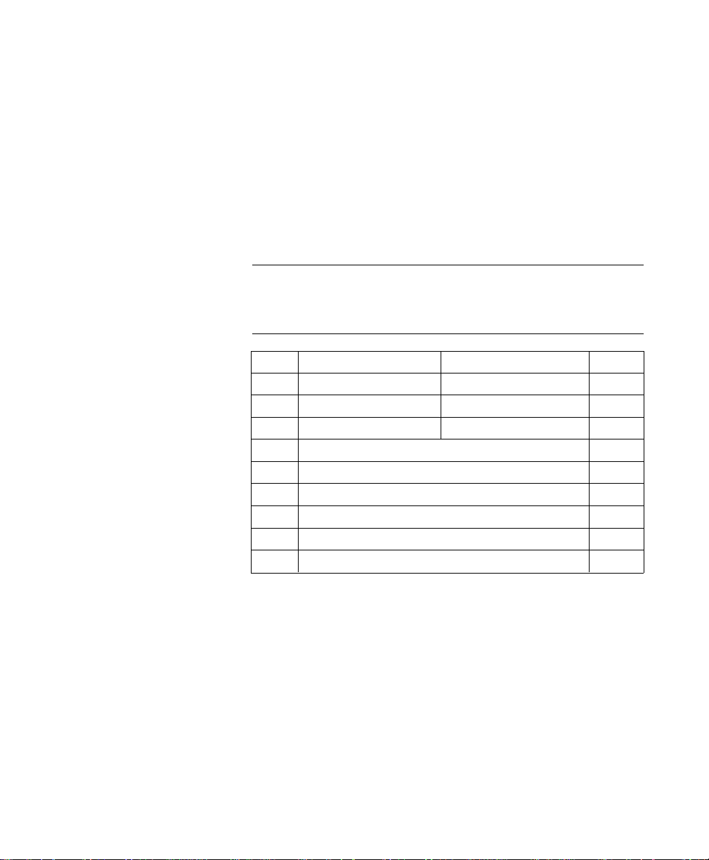
The Simple Color palettes are show n below :
Single Plane (value = 1)
Index Color
0 White
1 Black
3-Plane RGB (value = 3)
Index Color
0 Black
1 Red
2 Green
3 Yellow
4 Blue
2-4 Using Color Modes2-4 Using Color Modes
5Magenta
6 Cyan
7 White
3-Plane CMY (value = –3)
Index Color
0 White
1 Cyan
2Magenta
3 Blue
4 Yellow
Page 28
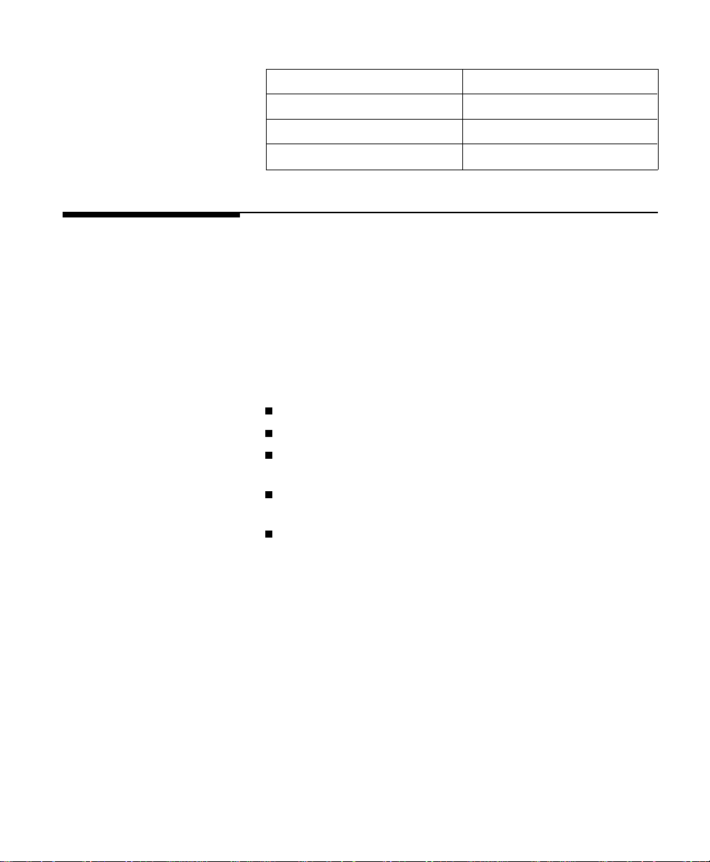
Index Color
5 Green
6 Red
7 Black
PCL Im aging
Mode
Configure Image
Data (CID)
Command
The PCL Imaging mode, entered using the Configure Image
Data (CID) command (?*v#W), creates a variable-sized
programmable palette. It provides half ton ing in the printer,
with multiple color spaces, pix el en codin g mode s, and
reprogrammable palettes.
The CID command provides con fig u ration infor mation for
creating palettes and tran smitting raster data. The CID
command performs the following:
Designates the color space for the defau lt palette
Designates the size of the palette to be created
Provides data for transf or ming color - sp ace -spec ific
values into device-specific values
Provides data for transfor ming devic e-de penden t data
(monitor RGB) to device- ind epen de nt (Colorimetric RGB)
Designates the format of ra ster data and how primary
components are combined to yie ld the r aste r
representation
?*v#W[binar y da ta]
# = Number of data bytes
Default = NA
Range = Short form: 6 bytes
Long form: >6 bytes
Usi ng Color Modes 2 -5Usi ng Color Modes 2 -5
Page 29
Invalid config ur ation s of the CID comman d are igno re d and
the data discarded. An y sign s in the value field are ignor ed.
The data fields in this command must contain byte-alig ned
binary data, not ASCII data.
This command has two forms: the six-byte sho rt for m
described below, and the long form consisting of these six
bytes, plus additional in formation spe cif ic to the color space .
Common 6-Byte
Header
The short and long form s of the CID command use a
common 6-byte header, regardless of which color space is
specified. The header data fields, whose mean ing may v ary
according to the color spaces, are present in all color space
specification s. Th e short for m and lon g for m of the CID
command are explained separ ately in the following pag es.
Byte 15 (MSB) 8 7 0 (LSB) Byte
0
Color space
(UBYTE)
2
Bits/index
(UBYTE)
4
Bits/primary # 2
(UBYTE)
Byte 0 (Color Space)
This byte specifies the color space. The range of values is 0
through 4. All oth er v alues are ignor ed.
Byte V alue Color Space
0 Device RGB (defaul t)
Pixel encoding
mode (UBYTE)
Bits/primary # 1
(UBYTE)
Bits/primary # 3
(UBYTE)
1
3
5
2-6 Using Color Modes2-6 Using Color Modes
1 Device C M Y
2 Colorimetric RGB Spaces
3 CIE L*a*b*
4 Luminance-Chrominance Spaces
Page 30
Note Colorimetric RGB color spaces are based on the 1931
standard 2-deg re e ob server and specified by CIE xy
chromaticity coordinate s. They use the standard D6500
viewing illuminan t and a 45-deg r ee illumination model
with a 0-degree co llec tor geometry for reflective data.
CIE L*a*b* is the CIE 1976 Uniform Color Space based on
the 1931 standard 2-degre e observ er, and using a 45-degree
illumination model with a 0-degree c ollec tor geometr y for
reflective data. Th e viewin g illumin an t is the standard
D6500 illuminant.
Luminance-Chromin an ce spaces are a 3x3 linear
transformatio n from Color imetr ic RGB. Like CIE L*a*b*,
achromatic data is contained in one channel an d chr omatic
data shares the other two chan nels.
Byte 1 (Pixel Enco di n g Mo de)
Byte number 1 designates the format in whic h raster data
is to be transmitted and interprete d. Th e range of this
value field is 0 to 3. All other values for this field are
ignored.
Byte V alue Pi xel En co ding Mod e Restrictions
0
1
Indexed by Plan e
(default)
Bits/index must be
1, 2, 3, 4, 5, 6, 7, or 8
Indexed by Pixel Bits/index must be
1, 2, 4, or 8
2
Direct by Plan e 1 bit per primary
(RGB or CMY only)
3
Direct by Pixel 8 bits per primary
(All Color Spaces)
You need one plane or on e bit/ pixel for each power of two
colors in the palette. For examp le, a 256-co lor palett e
requires 8 plane s or 8 bits/pixel (2
8
= 256).
Usi ng Color Modes 2 -7Usi ng Color Modes 2 -7
Page 31

MODE 0: INDEXED BY PLANE
In mode 0 (default), succ essiv e plane s of data are sent for
each raster row. A plane contains one bit for each pix el in a
row. A pixel is not fully def ine d until it has r eceiv ed all the
planes for that row. The planes in a row form index
numbers that define a pixel by se lec ting a palette entr y.
Assuming 3 bits per index, the underlined column of bits
below is the palette index for pixel 3 of row 1 (i1 is lsb; i3 is
msb). Note that the T ran sf er Raster Data by Plane
command (?*b#V) is used for all planes except the last
plane of each row, which uses the Tr an sfer Raster Data by
Row command (?*b#W).
Example:
?*b#V row 1 plane 1 i1 i1
?*b#V plane 2 i2 i2
?*b#W plane 3 i3 i3
?*b#V row 2 plane 1 i1 i1 i1 i1 i1
?*v6W 00 00 03 08 08 08 # Binary data for CID
represented in hex. Sets
color space to RGB, pixel
encoding mode to 0, palette
size to 8 (3 planes), last 3
bytes ignored.
?*r1A # Start raster .
?*b1V10110000 . . . # Transfer plane 1 (the first
bit for each pixel in the first
row). Combining each bit
with its corresponding bit in
the other plane s forms the
palette index number for
that pixel.
?*b1V011 10000 . . . # T ran sfer plane 2 (the
second bit for each pixe l in
the row).
i1 i1 i1
i2 i2 i2
i3 i3 i3
2-8 Using Color Modes2-8 Using Color Modes
Page 32

?*b1W10101000 . . . # T ran sfer plane 3 (the third
bit for each pixel in the row)
and move to the next row.
Note that the ?*b#W
command is used to send
the last plane of each row.
Usi ng Color Modes 2 -9Usi ng Color Modes 2 -9
Page 33

Example:
MODE 1: INDEXED BY PIXEL
In mode 1, each pixel in a row i s fully specifie d befor e any
bits are sent for the next pixel. The bits for each pix el form
a palette index number. Assuming 4 bits per index, the
underlined block below is the palette index for pixel 2 of
row 1 (i1 is lsb).
?*b#W row 1 i4 i3 i2 i1
?*b#W row 2 i4 i3 i2 i1 i4 i3 i2 i1 . . .
?*b#W row 3 i4 i3 i2 i1 i4 i3 i2 i1 . . .
?*v6W 00 01 04 04 04 04 # Binar y data for CID
?*r1A # Start raster.
?*b1W45 # Most significant nibble
?*b1W6A # First pixel is index 6,
?*b1W03 # First pixel is index 0,
i4 i3 i2 i1 . . .
represented in
hexidecimal. Sets color
space to RGB, pixel
encoding mode to 1, palette
size to 16 (4 bits to address
palette index). Last 3 bytes
ignor ed.
selects palette index 4 for
the first pixel. Second pixel
is set to index 5. Move to
the ne xt row.
second pixel is index 10.
Move to the next row.
second pixel is index 3.
Move to the next row.
2-10 Using Color Modes2-10 Using Color Modes
Page 34

Example:
MODE 2: DIRECT BY PLANE
In mode 2, the color raster data f or eac h row i s down loaded
by sequential planes, but the pixel c olor is direc tly
specified, rather than forming an index into the palette.
The underlined block below def ine s the actu al primar ies for
pixel 3 of row 1.
?*b#V row 1 red plane r r
?*b#V green plane g g
?*b#W blue plane b b
?*b#V row 2 red plane r r r r r
?*v6W 00 02 01 01 01 01 # Binary data for CID
represented in hex. Sets
color space to RGB, pix el
encoding mode to 2. Palette
size is ignored because this
is a direct selection, not
indexed. Last 3 bytes are
always 1 for this mode.
?*r1A # Start raster.
?*b1V10110000 . . . # Transfer plane for primary
color 1. Each bit tu r ns on or
off the red primary for the
pixel defined by the
corresponding bits in each
plane.
?*b1V011 10000 . . . # T r ansfe r plane for primary
color 2. Each bit tu r ns on or
off the green primary of the
pixel.
?*b1W10101000 . . . # Transfer plane for primary
color 3 and move to the next
row. Each bit turns on or off
the blue primary of the pixel.
r rr
g gg
b bb
Using Color Modes 2-11Using Color Modes 2-11
Page 35

Example:
MODE 3: DIRECT BY PIXE L
In mode 3, the color raster data is down loaded pixel by pixel
(as in mode 1), but each pixel dire ctly specifies each color
component (as in mode 2). Assumin g Device RG B spac e
with 8 bits per primary, the underline d block below defin e s
the actual color primar ies for pix el 1 of row 2.
?*b#W row 1 r7–r0 g7–g0 b7–b0 . . .
?*b#W row 2
r7–r0 g7–g0 b7–b0 . . .
?*b#W row 3 r7–r0 g7–g0 b7–b0 . . .
?*v6W 00 03 00 08 08 08 # Binary data for CID
represented in hex. Sets
color space to RGB, pixel
encoding mode to 3.
Palette size is ignored.
Send 8 bits to address each
primary valu e for a pixel.
?*r1A # Start raster.
?*b3W 45 06 30 # Each byte sets a primary
value for the first pixel
and moves to the next row
(45 specifies the red, 06
the green, and 30 the blue
component value of that
pixel).
2-12 Using Color Modes2-12 Using Color Modes
Byte 2 (Number of Bits per Index)
In all pixel encodin g modes, this byte sets the size of the
palette to 2
n
, where n is the number of bits per index.
In pixel encodin g modes 0 and 1 (index ed ), whe re raster
data is interpreted as indices into a palette, this value
specifies the number of bits required to acce ss all palette
entries.
In pixel encoding modes 2 and 3 (direct), this value
determines palette size, but has no effect on the
specification of raster data.
Page 36

Byte 3 (Number of Bits for Primar y #1 )
This byte is ignored in pixel enc od ing modes 0 and 1, but
affects the black and white re fer en ces in device -dep en den t
color spaces. In Devic e RG B, the black refer en c e for
primary #1 is set to 0 and the white referenc e is set to
n
2
– 1, where n is the number of bits for primary #1. These
referenc es are rev er sed in Devic e CM Y color space.
In pixel encoding mode 2, this byte is ignored except in
Device RGB and Device CMY color space, where it
designates the number of data bits needed to specify
primary #1, as well as the number of data planes to be
sent for primary #1.
In pixel encoding mode 3, this byte designates the
number of data bits needed to specify primar y #1.
A value of 0 defaults the black and white ref er ence value s
for primary #1 ac c or ding to the color space.
Byte 4 (Number of Bits for Primar y #2 )
This byte is ignored in pixel enc od ing modes 0 and 1, but
affects the black and white re fer en ces in device -dep en den t
color spaces. In Devic e RG B, the black refer en c e for
primary #2 is set to 0, and the white reference is set to
n
2
– 1, where n is the number of bits for primary #2. These
referenc es are rev er sed in Devic e CM Y color space.
In pixel encoding mode 2, this byte is ignored except in
Device RGB and Devic e CMY color spaces, wh ere i t
designates the number of data bits needed to specify
primary #2, as well as the number of data planes to be
sent for primary #2.
In pixel encoding mode 3, this byte designates the
number of data bits needed to specify primar y #2.
A value of 0 defaults the black and white ref er ence value s
for primary #2 ac c or ding to the color space.
Using Color Modes 2-13Using Color Modes 2-13
Page 37

Byte 5 (Number of Bits for Primar y #3 )
This byte is ignored in pixel enc od ing modes 0 and 1, but
affects the black and white re fer en ces in device -dep en den t
color spaces. In Devic e RG B, the black refer en c e for
primary #3 is set to 0, and the white reference is set 2
n
– 1,
where n is the number of bits for primary #3. These
referenc es are rev er sed in Devic e CM Y space.
In pixel encoding mode 2, this byte is ignored except in
Device RGB and Device CMY color space, where it
designates the number of data bits needed to specify
primary #3, as well as the number of data planes to be
sent for primary #3.
In pixel encoding mode 3, this byte designates the
number of data bits needed to specify primar y #3.
A value of 0 defaults the black and white ref er ence value s
for primary #3 ac c or ding to the color space.
2-14 Using Color Modes2-14 Using Color Modes
Page 38

Short Form of
CID Command
(Configure
Image Data)
The Short Form of the CID command involve s sendin g just
the common 6-byte header. By changing the value of byte 0
(color space ), the short form c an spec ify the follow ing fiv e
color spaces:
Device RGB ?*v6W[0x00, . . . ]
Device CMY ?*v6W[0x01, . . . ]
CIE L*a*b* ?*v6W[0x 03, . . . ]
The following data rang es are allowed in CIE L*a*b*. Hue
is preserved when out-of -r ang e data is clipped.
L* = 0.0 to 100.0
a* = –100.0 to 100.0
b* = –100.0 to 100.0
Colorimetric RGB (SMPTE RGB) ?*v6W[0x02, . . . ]
Non-linear SMPTE RGB with a 2.2 gamma and 1.0 gain is
the default Color imetr ic RGB color space . The shor t for m
allows the following ranges:
R = 0.0 to 1.0
G = 0.0 to 1.0
B = 0.0 to 1.0
Luminance-Chrominance (YUV) ?*v6W[0x04, . . . ]
YUV, which is a linear tran sformation from SMPTE RGB,
is the default Luminanc e-Ch romin an ce color sp ace . The
short form allow s the follow in g rang es:
Y = 0.0 to 1.0
U = –0.89 to 0.89
V = –0.70 to 0.70
Using Color Modes 2-15Using Color Modes 2-15
Page 39

Data Range Sca ling
White and black refer en ces defin e the encodin g range
for devic e-de pen den t co lor spaces. Ho we ve r, deviceindependen t color spaces requ ire input data pre- scaled to
the range 0 to 255. For examp le, to use th e short for m for
the default YUV color space , th e input data mu st hav e th e
following ranges:
Y = 0.0 to 1.0
U = –0.89 to 0.89
V = –0.70 to 0.70
The user must linearly scale (y = mx + b) the input data to
the range 0 – 255:
Y = 0 (0.0) to 255 (1.0)
U = 0 (–0.89) to 255 (0.89)
V = 0 (–0.70) to 255 (0.70)
2-16 Using Color Modes2-16 Using Color Modes
Page 40

Long Form of
CID Command
(Configure
Image Data)
Note The short form for the De vic e RGB color space defau l ts
In addition to the short form, th er e is also a long form of the
CID command for eac h color space. In devic e-in de pen den t
color spaces, the lon g form can spec ify primar ies othe r than
the defaults provided by the short form. For example, a
Sony T r initron RGB primary base can be selecte d for
Colorimetric RGB instead of the default no n- line ar SMPTE
RGB primaries.
Device RGB (Long Form)
The long form for the D evice RGB colo r spac e (valu e field
18) provides explicit entr y of black and white ref er ence s
(range is –32767 to 32767). Black and white refer ence s are
used in the direct pix el encod ing modes (2,3) to set relative
limits for raster data; they are also used when specifyin g
the primary components of new palette entries (?*v#A,
?*v#B, ?*v#C). Black and white referenc es hav e no effec t
on CID default palette colors. Th e refer enc e values are
specified as 16-bit signed integers (sint16).
each primary’s black refere nce to 0 and the white ref eren ce
n
to 2
–1, where n is the number of bits for that primary.
Byte 15 (msb) 8 7 (lsb) 0 Byte
0 Colo r space Pixel encoding mode 1
2 Bits per index Bits per primary #1 3
4 Bits per primary #2 Bits per primary #3 5
6 White r efer en ce for primar y #1 (sint 16) 7
8 White r efer en ce for primar y #2 (sint 16) 9
10 White reference for primary #3 (sint 16) 11
12 Black reference for primary #1 (sint16) 13
14 Black reference for primary #2 (sint16) 15
16 Black reference for primary #3 (sint16) 17
Using Color Modes 2-17Using Color Modes 2-17
Page 41
Device CMY (Long Form)
The long form for the D evice CMY color sp ace (value field i s
18) provides explicit entr y of black and white ref er ence s
(range is –32767 to 32767). Black and white refer ence s are
used in the direct pix el encod ing modes (2,3) to set relative
limits for raster data; they are also used when specifyin g
the primary components of new palette entries (?*v#A,
?*v#B, ?*v#C). Black and white referenc es hav e no effec t
on the default CID palette color s. The refere nce value s are
specified as 16-bit signed integers (sint16).
Note The short form for the Device CM Y color space def aults
each primary’s white refer en ce to 0 and black r efer enc e to
n
2
–1, where n is the number of bits for that primary.
Byte 15 (msb) 8 7 (lsb) 0 Byte
0 Color space Pixel encodin g mode 1
2 Bits per index Bits per primary #1 3
4 Bits per primary #2 Bits per primary #3 5
6 White reference for primary #1 (sint16) 7
8 White reference for primary #2 (sint16) 9
10 White referen ce for primary #3 (sint16) 1 1
12 Black referenc e for primary #1 (sint16) 13
14 Black referenc e for primary #2 (sint16) 15
16 Black referenc e for primary #3 (sint16) 17
2-18 Using Color Modes2-18 Using Color Modes
Page 42

CIE L*a*b* (Long Form)
The long form for the CIE L*a*b* color space allows a
larger data range than the shor t form defaults:
L* = 0.0 to 120.0 (greater than the short form by 20.0)
a* = –159.0 to 128.0 (less than the short form by –32.0 and
greater than the short form by 28.0)
b* = –120.0 to 80.0 (less than the short form by 20.0)
Note Although the data ranges may ex ten d bey ond the def ault
data ranges specified in the shor t for m of the CID
command, the printer will c lip the data to the short form
data ranges.
Maximum and minimu m valu es are spec ified for eac h
primary color. Floating point data must be linearly scaled
(y = mx + b) to the range 0 – 255.
Since a* and b* have no theor etic al limits, L*a*b* data may
be sent outside CID constraints. Then data is clipped to
preserve hue and compressed to the device’s printable
gamut.
Using Color Modes 2-19Using Color Modes 2-19
Page 43

The white point is based on the standard D6500 illumin ant.
Byte 15 (msb) 8 7 (lsb) 0 Byte
0 Color space Pixel encoding mode 1
2 Bits per index Bits per primary # 1 3
4 Bits per primary #2 Bits per primary #3 5
6 Minimum L* value (most significan t wor d) * 7
8 Minimum L* value (least significan t wor d) * 9
10 Maximum L* value (msw) 11
12 Maximum L* value (lsw) 13
14 Minimum a* value (msw ) 15
16 Minimum a* value (lsw ) 17
18 Maximum a* value (msw ) 19
20 Maximum a* value (lsw ) 21
22 Minimum b* value (msw ) 23
24 Minimum b* value (lsw ) 25
26 Maximum b* value (msw ) 27
28 Maximum b* value (lsw ) 29
FLOATING PO INT FO RMA T*
The following format is used for device -in dependent color
floating point specifications:
2-20 Using Color Modes2-20 Using Color Modes
31 30 23 22 0
Sign Exponent Fractional Portion
The above single-prec ision , 32-bit floatin g point
specification is fully complian t with the IEEE Floating
Point Formats.
Page 44

Colorimetric RGB (Long Form)
The long form for Colorimetric RGB allows specificatio ns
other than the def ault n on -lin ear SMPTE RGB with a 2.2
gamma and 1.0 gain. Each RGB primar y and th e white
point is specified in the CID data field by chr omatic ity
coordinates (CIE xy). Th e tristimulu s lumin anc e Y value of
the white point is assumed to be 100% and is therefo re not
specified. For color spaces that are lin ear tran sfor mation s
from CIE XYZ tristimulus coord inate s, gamma and gain are
set to 1.0; otherwise they are set appro priately. Colorime tric
RGB spaces can be used for any monitor having primaries
specified as CIE xy chromaticity coordinates with white
point, such a s the Son y Trinitron or Hitachi Color Monitor.
Byte 15 (msb) 8 7 (lsb) 0 Byte
0 Color space Pixel encoding mode 1
2 Bits per Index Bits per primary #1 3
4 Bits per primary #2 Bits per primar y #3 5
6 x Chromaticity for red primary (msw) 7
8 x Chromaticity for red primary (lsw) 9
10 y Chromaticity for red primar y (msw) 11
12 y Chromaticity for red primar y (lsw) 13
14 x Chromaticity for gr een pr imary (msw) 15
16 x Chromaticity for gr een pr imary (lsw) 17
18 y Chromaticity for gr een pr imary (msw) 19
20 y Chromaticity for gr een pr imary (lsw) 21
22 x Chromaticity for blue primar y (msw) 23
24 x Chromaticity for blue primar y (lsw) 25
26 y Chromaticity for blue primar y (msw) 27
28 y Chromaticity for blue primar y (lsw) 29
30 x Chromaticity for white poin t (m sw) 31
32 x Chromaticity for white poin t (l sw) 33
34 y Chromaticity for white poin t (m sw) 35
36 y Chromaticity for white poin t (l sw) 37
Using Color Modes 2-21Using Color Modes 2-21
Page 45

38 Gamma for red primary (msw) 39
40 Gamma for red primary (lsw) 41
42 Gain for red primary (msw) 43
44 Gain for red primary (lsw) 45
46 Gamma for green primary (msw) 47
48 Gamma for green primary (lsw) 49
50 Gain for green primary (msw) 51
52 Gain for green primary (lsw) 53
54 Gamma for blue primary (msw) 55
56 Gamma for blue primary (lsw) 57
58 Gain for blue primary (msw) 59
60 Gain for blue primary (lsw) 61
62 Minimum re d value (msw) 63
64 Minimum red value (lsw) 65
66 Maximum re d value (msw) 67
68 Maximum red value (lsw) 69
70 Mi nimum green value (msw) 71
72 Minimum green value (lsw) 73
74 Ma ximum green value (msw) 75
76 Maximum green value (lsw) 77
78 Minimum blue value (msw) 79
80 Minimum blue value (lsw) 81
82 Maximum blue value (msw) 83
84 Maximum blue value (lsw) 85
2-22 Using Color Modes2-22 Using Color Modes
Page 46

Luminance-Chrominance (Long Form)
The long form for Lumin an c e-Ch r omin anc e allow s color
spaces other than th e default Y U V, such as Kodak Photo
YCC, the proposed JPEG and TIFF 6.0 YCrCb standard,
YES, and YIQ. These Luminance-Chrominance color spaces
are derived fro m the Color imetr ic RGB space u sing a 3x3
transformation matrix. The tristimulus luminance y value
of the white point is assumed to be 100% and is therefore
not specified.
Byte 15 (msb) 8 7 (lsb) 0 Byte
0 Color space Pixel encoding mo de 1
2 Bits per index Bits per primary #1 3
4 Bits per primary #2 Bits per primar y #3 5
6 Encoding for pr imary #1 R (msw) 7
8 Encoding for pr imary #1 R (lsw) 9
10 Encoding for pr imary #1 G (msw) 11
12 Encoding for pr imary #1 G (lsw) 13
14 Encoding for primary #1 B (msw) 15
16 Encoding for primary #1 B (lsw) 17
18 Encoding for primary #2 R (msw) 19
20 Encoding for primary #2 R (lsw) 21
22 Encoding for pr imary #2 G (msw) 23
24 Encoding for pr imary #2 G (lsw) 25
26 Encoding for primary #2 B (msw) 27
28 Encoding for primary #2 B (lsw) 29
30 Encoding for primary #3 R (msw) 31
32 Encoding for primary #3 R (lsw) 33
34 Encoding for pr imary #3G (msw) 35
36 Encoding for pr imary #3 G (lsw) 37
38 Encoding for primary #3 B (msw) 39
40 Encoding for primary #3 B (lsw) 41
42 Minimum primary #1 valu e (m sw) 43
44 Minimum primary #1 valu e (l sw) 45
46 Maximum primary #1 valu e (m sw) 47
48 Maximum primary #1 valu e (l sw) 49
Using Color Modes 2-23Using Color Modes 2-23
Page 47

50 Minimum primary #2 valu e (m sw) 51
52 Minimum primary #2 valu e (l sw) 53
54 Maximum primary #2 valu e (m sw) 55
56 Maximum primary #2 valu e (l sw) 57
58 Minimum primary #3 valu e (m sw) 59
60 Minimum primary #3 valu e (l sw) 61
62 Maximum primary #3 valu e (m sw) 63
64 Maximum primary #3 valu e (l sw) 65
66 x Chromaticity for red primary (msw) 67
68 x Chromaticity for red primary (lsw) 69
70 y Chromaticity for red primary (msw) 71
72 y Chromaticity for red primary (lsw) 73
74 x Chromaticity for gree n primar y (msw) 75
76 x Chromaticity for gree n primar y (lsw) 77
78 y Chromaticity for gree n primar y (msw) 79
80 y Chromaticity for gree n primar y (lsw) 81
82 x Chromaticity for blue primary (msw) 83
84 x Chromaticity for blue primary (lsw) 85
86 y Chromaticity for blue primary (msw) 87
88 y Chromaticity for blue primary (lsw) 89
90 x Chromaticity for white poin t (msw) 91
92 x Chromaticity for white poin t (lsw) 93
94 y Chromaticity for white poin t (msw) 95
96 y Chromaticity for white poin t (lsw) 97
98 Gamma for red primary (msw) 99
100 Gamma for red primary (lsw) 101
102 Gain for red primar y (m sw) 1 03
104 Gain for red primar y (l sw) 105
106 Gamma for green primary (msw) 107
108 Gamma for green primary (lsw) 109
11 0 Gain for green primary (msw) 11 1
11 2 Gain for green primary (lsw) 11 3
114 Gamma for blue primary (msw) 115
116 Gamma for blue primary (lsw) 117
11 8 Gain for blue primary (msw) 119
2-24 Using Color Modes2-24 Using Color Modes
Page 48

120 Gain for blue primary (lsw) 121
Examples Using
the CID Command
Example: The short form CID command, as a C function, can look
The following examples illustrate u sing the CID command’s
short and long forms for each color sp ace . For clarity, data
is shown as ASCII, rath er than binary and the CID
command (?*v#W) is shown as “CID”. Th e follow in g for ma t
is used:
CID ( data , data , . . . )
Device RGB or Device CMY
SHORT FORM
CID(0,1,8, 8,8, 8) Device RGB, 8 bits/pixel indexed
CID(1,1,8, 8,8, 8) Device CMY, 8 bits/pixel indexed
like this:
short_cid(Co lor _mode , Pixel_mod e, Bitsper Index ,
BitsperColor_1, Bitspe rCo lor _2, Bitsper Color _3)
{
int Color_mode, Pixel_mode , BitsperIndex,
BitsperColor_1, Bitspe rCo lor _2, Bitsper Color _3;
printf(“\033*v6W%c%c%c%c%c%c”,Color_mode,
Pixel_mode, BitsperIndex, BitsperColor_1,
BitsperColor_2, BitsperColor_3);
}
LONG FORM
CID(0,1,8, 8,8, 8, Device RGB, 8 bits/pixel indexed
0,0,0 White reference
100,100,100) Black reference
Using Color Modes 2-25Using Color Modes 2-25
Page 49

CIE L*a*b*
SHORT FORM
CID(3,3,0, 8,8, 8) L*a*b*, direct 8 bits/primary
LONG FORM
CID(3,3,0, 8,8, 8, L*a*b*, direct 8 bits/primary
0.0, 100.0, L* data encoding
–100.0, 100.0, a* data encoding
–100.0, 100.0) b* data encoding
Non-Linear SMPTE RGB, 2.2 Gamma, 1.0 Gain
SHORT FORM
CID(2,3,0, 8,8, 8) RGB, direct 8 bits/primar y
LONG FORM
CID(2,3,0,8,8,8,
0.64, 0.34,
0.31, 0.60,
0.16, 0.07,
0.3127, 0.3290,
2.2, 1.0,
2.2, 1.0,
2.2, 1.0,
0.0, 1.0,
0.0, 1.0,
0.0, 1.0)
RGB, direct 8 bits/primary
|
| Chromaticity coordinates
| for RGB & White Point
|
*
* Gamma and gain for RGB
*
|
| Data range encodin g
|
2-26 Using Color Modes2-26 Using Color Modes
Page 50

Non-Li nea r Son y Trinitron
SHORT FORM
Not Applicable
LONG FORM
CID(2,3,0,8,8,8
0.62, 0.34,
0.30, 0.58,
0.15, 0.09,
0.2800, 0.2933,
2.3, 1.19,
2.3, 1.19,
2.3, 1.19,
0.0, 255.0,
0.0, 255.0,
0.0, 255.0)
YUV Chrominance-Luminance Color Space
SHORT FORM
CID(4,3,0, 8,8, 8) YUV, direct 8 bits/primary
YUV Chromi nance -Lumi n ance wit h So ny Trinitron
LONG FORM
CID(2,3,0,8,8,8
0.30,0.59,0.11,
–0.30,0.59,0.89,
0.70,–0.59,–0.11,
0.0,255.0
–227.0,227.0,
–179.0,179.0
0.62,0.34,
0.30,0.58,
0.15,0.09,
0.2800, 0.2933,
2.3,1.19,
2.3,1.19,
2.3,1.19)
RGB, direct 8 bits/primar y
|
| Chromaticity coordinates
| for RGB
| White Point
*
* Gamma and gain for RGB
*
|
| Data range encoding
|
YUV, direct 8 bits/primary
|
| 3x3 YUV matrix
|
*
* Data encoding
*
|
| Chromaticity
| coordinates
| chromaticity white point
*
* Gamma and
* gain for RGB
Using Color Modes 2-27Using Color Modes 2-27
Page 51

HP-GL/2 Imaging
Mode
The HP-GL/2 Imaging Mode pr ovides a way of using vector
commands in printing docu men ts. Although the default
PCL and HP-GL/2 palettes are not the same, when
transferrin g from PCL to HP-G L/2, ac tive palet te
information does stay th e same. You can switch betw een
PCL and HP-GL/ 2 and use th e same palette, and you can
also modify palettes using either PCL or HP-GL/2.
Compared to monochrome printers, the Color LaserJet and
DeskJet 1200C color printers have some commands tha t
are new and/or modified for use with colo r pr in ters.
Chapter 7 describes the new or modified HP-G L/ 2
commands.
If you are not familiar with usin g HP-GL/ 2, se e the PCL 5
Printer Language Technica l Reference Manu al. It provides a
detailed explanation of using HP-GL/2.
2-28 Using Color Modes2-28 Using Color Modes
Page 52

3
U sing PalettesU sing Palettes
Introduction A palette is a collection of color specifications selected using
index numbers. Th e figur e below illustr ates a palette. Each
palette entry associates an index numbe r with th ree
primary color comp onen t s. For HP-GL/ 2 purposes on ly, a
pen width is also associated with each palette entry.
Page 53

In non-raster mode, the current palette contains all the
colors available to the printer. In raster mode, indexed color
selection uses the palette, but direc t selectio n does not.
Default palettes are created by all the PCL color mode s
(Black and White, Simple Color, PCL Imaging, and
HP-GL/2 Imagin g) . The activ e palette may be modified
when in the PCL Imagin g or HP-G L/2 imag ing modes, but
not when in the Simple Color or Black and White modes.
When switching between PCL 5 and HP-GL/2 contexts, the
active palette is automatically transferred.
Multiple palettes can exist in th e system via the Palette ID
and Palette Stack mechanism. However, only one palette at
a time can be active. A palette created in the PCL co nte xt
remains active and unchanged when switching to the
HP-GL/2 con tex t, and a palette created in th e HP-G L/ 2
context remains active and unchanged when switching to
the PCL contex t. Per fo rmin g a reset or ente rin g PJL
overwrites th e activ e palette with th e defau lt black and
white palette.
Whenever a new palette is created, th e curre ntly or
previously ac tiv e palette is destr oyed. A new palette is
created by power -on and also by the following commands:
PCL Reset (?E)
Simple Color (?*r#U)
Configure Image Data (?*v#W)
HP-GL/2 Initialize (IN)
The active palette can be saved by pushin g it onto the
palette stack with the Push/Po p Palette command (?*p#P).
Popping a palette from the stack destro ys the active
palette—the popped palette bec omes the active palette.
3-2 Using Palettes3-2 Using Palettes
Page 54

Saving the Palette The curren t palette is destroyed when a new palette is cre-
ated. The Push/Pop Palette command (?*p#P) can save
(push) the curr ent palette and then restore (po p) it.
Push/Pop Palette
Command
This command pushes or pops the palette from the palette
stack.
?*p#P
# = 0 Push (save) palette
1 Pop (restore) palette
Default = 0
Range = 0, 1 (invalid v alues are ignored)
A value of 0 (?*p0P) pushes a copy of the active palette onto
the palette stack. When a palette is pushed, the active
palette is not affected.
A value of 1 (?*p1P) pops the most recently pushed palette
and destroys the activ e palette; the popped palette bec omes
the active palette. As with any stack, the last item pushed
is the first item popped.
Pushing a palette saves the following parameters:
Color definition s for eac h palette en try
Pen widths (for HP-GL/2 use)
Color space specification
Black and white refer en ces
Number of bits per index
Pixel encodin g mode
Number of bits per primary
Gamma correction
View in g illuminan t
Color lookup tables
Usi ng P alettes 3-3Usi ng P alettes 3-3
Page 55

Render algo rithm
Downloaded dith er matrix
Pushing a palette does not save the follow in g parameter s.
Foreground color
Color components: 1st, 2nd, and 3rd
Finish mode
Monochrome print mode
The palette stack depth is limited by printer memory.
Attempts to push a palette with insufficient memory cause
an out-of-memor y err or. Attempts to pop from an empty
stack are ignored.
Macros can push and po p palettes. A palette that wa s
popped in an executed macro remains in effect at the end of
the macro (thi s is not true for “called” or “over laid” macr os).
PCL reset commands (?E) and exits to PJL cause the
printer to empty the palette stack an d overw rite the activ e
palette with a non-programmable black an d white palette.
The HP-GL/2 command s IN and DF have no effect on the
palette stack, but they do destroy the active palette and replace it with the default HP- GL/2 palette.
3-4 Using Palettes3-4 Using Palettes
Page 56

Palette
Management
by ID
All palettes hav e a unique ID (identification number). The
default black and white palette create d on power -u p or ?E
has an ID of 0.
Palette management by ID lets applications have multiple
palettes. As shown below, multiple palettes can exist in two
areas: the palette stack and the palette store. The stack
holds palettes that are pushed via a Push /P op Palette co mmand; the store holds palettes havin g palette IDs.
Usi ng P alettes 3-5Usi ng P alettes 3-5
Page 57

Palettes on the stack may not be selected by ID, since only
a copy of a palette is pushed onto the stack; the original palette and ID remain in the palette stor e. A palette popped
from the stack goes into the pale tte store, beco mes the ne w
active palette, an d assumes the ID of the pr eviou sly activ e
palette, which is overwritten. Only one palette at a time
may be active.
Management by ID allows applications to tag d ata, hav e
multiple raster conf igur ation s, and have palettes for different color spaces—all withou t re conf igu rin g the activ e pa lette. For example, one palette can be created for PCL text,
one for HP-GL/2 primitives, one for simple raster, and one
for 24-bit raster. The applicatio n can then switch between
palettes according to what is being sent to the prin ter.
Selecting a new active palette changes the PCL grap hic s
state. Besides color entries, a palette also contain s the
graphics state at the time the bitmap represen tation of the
palette colors was created . This guaran tees co lor reprod uc tion integrity by insuring that the same color specification
triplet always produ ces th e same bitmap represen tation .
As described below, the Select Palette (?&p#S), Palette Con-
trol (?&p#C), and Palette Contr ol ID ( ?&p#I) commands
implement the three basic operatio ns of manageme nt by ID.
Selection of the active palette
Deletion of palettes
Copying of palettes
3-6 Using Palettes3-6 Using Palettes
Page 58

Select Palette
Command
The Select Palette comman d selects a new active palette by
specifyin g an ID number. The previously active palette i s
unchanged.
?&p#S
# = Palette ID number
Default = 0
Range = 0 to 32767 (command is ignored for out-
of-range values)
This command activates the designated palette in the palette store. The command is ignored if the specifie d ID
matches the active palette’s ID, or if no palette with that ID
exists. The designated ID is saved as the palette select ID
in the curren t modified pr in t env ir onmen t.
This command can be used to de-select th e activ e palette
and select as the new active palette a palette created by the
Palette Control command (?&p#C). For example, to copy
the active palette to an ID of 44 and select the new palette
to use or modify, send ?&p44i6c44S.
When a palette creation command is receiv ed such as Configure Image Data (?*v#W), Simple Color (?*r#U), or an
HP-GL/2 IN, the cre ated palette ov erw rite s the activ e palette and is assigned the curren t palette selec t ID, which is
unchanged.
A palette popped from the stac k overw rite s the active palette, and is assigned the current palette select ID , which is
unchanged.
?E resets the palette select ID value to 0 and deletes all palettes in the palette stack and palette store, includin g the active palette which is replaced by a default PCL fixed black
and white palette with a palette selec t ID valu e of 0.
Usi ng P alettes 3-7Usi ng P alettes 3-7
Page 59

Macros affect the palette select ID valu e as follows:
Calling or Overlaying a macr o—sav es the ID valu e and a
copy of the active palette. Upon macro exit, th e restor ed
palette again becomes the active palette with the
restored ID. An ex isting palette with this ID i s deleted.
Executing a macro —do es not save th e ID value or the
active palette; changes re main in effect.
Palette Control ID The Palette Control ID command specif ies the ID number
to be used by the Palette Control Command .
?&p#I
# = Palette ID number
Default = 0
Range = 0 to 32767 (command is ignored for out-
of-range values)
3-8 Using Palettes3-8 Using Palettes
The ID number specifie d by this command is saved as
the palette control ID in the curren t modifie d print
environme nt and is used by the Palette Control co mmand
(?&p#C).
?E or power-up resets the palette contr ol ID to 0, which is
then the default black and white palette ID.
Macros affect the palette con tr ol ID value as follows:
Calling a macro—saves the value and r estor es the value
at exit.
Executing a macro —do es not save th e value; chang e s
remain in effect at exit.
Overlayin g a macro— copies the valu e befor e rese tting to
0, and restores at exit.
Page 60

Palette Control The Palette Control command pr ovides a mech an i sm for
marking and deletion of palettes.
?&p#C
# = 0 - Delete all palettes except tho se in the
stack (active palette delete d)
1 - Delete all palettes in the stack (active
palette is not affected)
2 - Delete palette (specified by Palette
Control ID )
6 - Copy active palette to ID specified by
Palette Control ID
Default = 0
Range = 0, 1, 2, 6 (command is ignored for
unsupported values)
A v alue of 0 deletes all palettes exce pt those on the
palette stack. The active palette is replaced by the
default black and white palette (ID 0). The palette
control ID is not used.
A v alue of 1 clears the palette stack. The active pale tte
is unaffected, an d the palette contr ol I D is not used.
A v alue of 2 deletes th e palette with th e specif ied palette
control ID if it exists; other wise th e command is ign or ed.
For example, to delete palette 53, send ?&p53i2C. If the
active palette’s ID is specified the active palette i s
replaced by the default blac k and white palette. This
option does not chan ge the palette contr ol ID value .
Note When the active palette is replac ed by the defau lt black
and white palette, the graphic s state associate d with the
previous palette is also replaced.
Usi ng P alettes 3-9Usi ng P alettes 3-9
Page 61

A value of 6 creates a copy of the active palette. The copy
receives the ID specif ied by th e last Palette Contr ol ID
command. For example, to copy the active palette to a
palette with an ID of 14, send ?&p14i6C. The copied
palette overwrites any palette that alr eady has an ID
equal to the palette control ID. The copie d palette does
not become the activ e palette. The comman d is ignored if
a palette is to be copied to its own ID.
The Palette Control command pr ov ides a way of manag ing
system memory by deleting palettes in either the stack or
store that are no longer in use.
Palette Control that is exerc ised durin g mac ros can have
significan t impact on palettes that ex i st within the syste m.
Deleting all palettes, or those on the stack, or the current
palette, or all those except on the stack can have adver se
effects when the macr o is exited. The adver se effe ct cou ld
be the deletion of the desired palette, and replaceme nt with
a black and white non-programmable palette.
3-10 Using Palettes3-10 Using Palettes
Page 62

Simple Color
Palettes
The Simple Color command (?*r#U) prov ides a quick way
to select colors from a fixed, non-progr ammable palette.
The Simple Color command overwrites the curren t palette
with one of the fixed pale ttes below. When the Simple Color
command is in effect, the PCL and HP-G L/2 comman ds that
modify a palette entry (NP, CR, PC, ?*v#A, ?*v#B, ?*v#C,
?*v*I, ?*t*I) are locked out. A popp ed simple c olor pale tte
cannot be modified and th e pixe l enc odin g mode re ve rts to
“index by plan e”. O nly the IN or the CID ( ?*v#W)
commands can create a modifiable palette.
As shown below, a value field of 1 (?*r1U) creates a black
and white palette. A valu e of 3 create s an 8-pen palette in
Device RGB color space . A value of –3 create s an 8-pen
palette in Device CMY co lor space. All of the se Simple Co lor
palettes are fixed and non-progr ammable.
Single Plane (value = 1)
Index Color
0 White
1 Black
3-Plane RGB (value = 3)
Index Color
0 Black
1 Red
2 Green
3 Yellow
4 Blue
5Magenta
6 Cyan
7 White
Using Palettes 3-11Using Palettes 3-11
Page 63

3-Plane CMY (value = –3)
Index Color
0 White
1 Cyan
2Magenta
3 Blue
4 Yellow
5 Green
6 Red
7 Black
3-12 Using Palettes3-12 Using Palettes
Page 64

CID Color Pale ttes The Config ure Imag e Data comman d, explain ed in detail in
Chapter 2, creates a palette based upon the parameters in
its data field. CID-created palettes are programmable: any
entry can be re a ssig n ed a differ en t col o r usin g PC L commands (?*v#A, ?*v#B, ?*v#C, ?*v*I) or HP-GL/2 com-
mands (CR, PC, NP). Default palettes vary by color space.
Device RGB
Palettes
The black and white refe renc es spec ified by the CID
command have no effect on the defau lt palettes below.
However, when a CID palette entry is reprogrammed with a
different color, the black and white referen c es are used to
specify the primar y compon ents of the n ew color.
Bits/I ndex = 1
Index Color
0 White
1 Black
Bits/I ndex = 2
Index Color
0 Black
1 Red
2 Green
3 White
Bits/Index = 3 through 8
Index Color
0 Black
1 Red
2 Green
3 Yellow
4 Blue
5Magenta
Using Palettes 3-13Using Palettes 3-13
Page 65

6Cyan
7 White
n > 7 Black
Device CMY
and Device-
Independent
Palettes
A CID command spec ify in g eith er a devic e-in dependen t
color space or the Device CMY color space creates the same
default palettes. This is becau se devic e- ind epen de nt color s
are transfor med in to the printer’s native space, Devic e CMY.
Bits/I ndex = 1
Index Color
0 White
1 Black
Bits/I ndex = 2
Index Color
0 White
1Cyan
2Magenta
3 Black
Bits/Index = 3 through 8
Index Color
0 White
1Cyan
2Magenta
3 Blue
4 Yellow
5 Green
6 Red
7 Black
n > 7 Black
3-14 Using Palettes3-14 Using Palettes
Page 66

HP-GL/2 Palettes Regardless of the color space, a default PCL palette i s
always different th an a defau lt HP-GL/ 2 palette. The
following table shows the default palettes established in
HP-GL/2. Like a defau lt CID palette , a default HP-G L/ 2
palette can be modified in either PCL or HP-GL/2 conte xts
using the following commands:
PCL
Color Components 1, 2, and 3 (?*v#A, ?*v#B, ?*v#C)
Assign Color Index (?*v#I)
HP-GL/2
Number of Pens (NP)
Pen Color A s sig n men t (PC)
Set Relative Color Range (CR)
Note The IN command always establishes the 8-pen palette.
T wo Pens
Pen Number Color
0 White
1 Black
Four Pens
Pen Number Color
0 White
1 Black
2 Red
3 Green
Using Palettes 3-15Using Palettes 3-15
Page 67

Eight Pens
Pen Number Color
0 White
1 Black
2 Red
3 Green
4 Yellow
5 Blue
6Magenta
7Cyan
n > 7 Black
3-16 Using Palettes3-16 Using Palettes
Page 68

Foreground C olor All PCL marking entitie s utilize “foreg ro und” color, which is
selected from the curren t palette u sing the Foregr ou nd
Color command (?*v#S). Foreground color interacts with
raster color depen din g on the print model c omman ds in
effect.
Foreground Color
Command
The Foreground Color comman d sets the fore grou nd co lor
to the specified inde x of the curre nt palette.
?*v#S
# = Index number into curr en t palette
Default = 0
Range = 0 to 2
Specified values that are out-of -rang e of the curre nt palette
are mapped into a new index as follows:
Index = Specified foreground index modulo palette size
For example, spec ifying a foreg r ound color ind ex of 10 wh en
the current palette size is 8 maps to 10 modulo 8, which is
equal to 2. If the current palette was created under
HP-GL/2, the in dex is mapped acc or din g to the HP-G L/ 2
mapping function.
Foregroun d colo r affects the follow ing PCL page markin g
primitives:
Text charac ter s (the y chan g e to the foreg rou n d colo r,
including underlining)
Solid or monochrome pattern ed rectan g ular ar ea fills
(rules)
Monochrome patterns (except HP-GL/2)
Raster images
(current palette size)
– 1
Using Palettes 3-17Using Palettes 3-17
Page 69

The following are no t affected:
User-def ine d color pattern s (for mat 1 down load patter ns)
HP-GL/2 markin g primitives (HP- GL /2 uses “ selec ted
pen”, but ignor es for eg r ou nd color)
Note Foregroun d colo r inter acts with color raster images. In the
printer, all color raster is resolved into three binar y raste r
planes of CMY. Foreground color is applied to these plane s,
modifying the color image. For no interac tion , set
foregroun d color to black wh en sendin g color ra ster images.
After a foreground co lor is selected, chan g in g any of the
following will not chang e for egr oun d colo r until a new
Foreground Color command (?*v#S) is issued:
Active Palette
Configure Image Data (CID) command
Render Alg orithm
User Defined Dither Matrix
Gamma Correction
Color Lookup Tables
View in g Illumin ant
As an exception, Monoch rome Pr in t Mode (?&b#M)
immediately maps foreground c olor to its equivalen t gray.
Similarly, deselection of Monochrome Pr in t Mode
immediately returns foreground color to its color equivalent.
3-18 Using Palettes3-18 Using Palettes
Page 70

Programming
Color Palette s
Except for the default black and white palette or the Simple
Color palettes (?*r#U), palette entries can be modified. The
three primary compon en t s of a color are specif ied and the
resulting color is assigned to the palette entry indicate d by
?*v#I.
In the explanation below, the term “compone nt” r efer s to
the color space primary colors. For example, if the curr ent
color space is CIE L*a*b*, compon ent 1 indic ates CI E L*,
component 2 indic ates CIE a*, and compon en t 3 indic ates
CIE b*.
Color Component
One
This command specifies the first primar y of the palette
entry designated by the Assign Color Index comman d
(?*v#I).
?*v#A
# = First Component
Default = 0
Range = –32767.0000 to 32767.0000 (up to 4
decimal places; command is ignor ed for invalid
configuration s )
The Assign Color In dex co mmand actually applies this
value and then resets it to 0.
Using Palettes 3-19Using Palettes 3-19
Page 71

Color Component
Two
This command specifies the sec on d primar y of the palette
entry designated by the Assign Color Index comman d.
?*v#B
# = Second Compon en t
Default = 0
Range = –32767.0000 to 32767.0000 (up to 4
decimal places; command is ignor ed for invalid
configuration s )
The Assign Color In dex co mmand actually applies this
value and then resets it to 0.
Color Component
Three
This command specifies the third primar y of the palette
entry designated by the Assign Color Index comman d.
?*v#C
# = Third Compon en t
Default = 0
Range = –32767.0000 to 32767.0000 (up to 4
decimal places; command is ignor ed for invalid
configuration s )
The Assign Color In dex co mmand actually applies this
value and then resets it to 0.
3-20 Using Palettes3-20 Using Palettes
Page 72

Assign Color Index This command assign s the thr ee curr en t color compon en t s
to the specified palette index number.
?*v#I
# = Index Number
Default = 0
n
Range = 0 to 2
bits per index (no assignmen t for out-of-r an g e
values)
This command reset s the color componen ts to 0 after
assignmen t. If th e specif ied ind ex number is greater than
the palette size, no index assignment is made, but the three
color componen t s are set to 0.
– 1, where n is the number of
Using Palettes 3-21Using Palettes 3-21
Page 73

4
ModiM odifying Output Colorfying Output Color
Introduction The previous chap ter s of thi s manual have been concerne d
with giving an over vie w of th e color pr in ting pr oc es s,
choosing co lor mod es, and using palettes. This por tion of
the manual explains ho w color can be modified to pr odu c e a
desired result, fro m using half ton e rende r alg orithms t o
change the way color is render ed, to compensatin g for the
yellow cast caused by a tungste n light source in a
photograph . Th e HP co lor printers can modify colors usin g
the following means:
Halftone render algorithms provide a way to modify
images based on a dither cell con c ept. The algorithm
chosen determines how specified colors are “rendered” as
dots on the printed pag e.
Color lookup tables can remap palette colors to
compensate for unw an ted color charac ter istic s of inpu t
data. For example, if a scanned photog r aph had a
reddish cast, a color lookup table cou ld be used to make
the printed image look as if it were taken under a more
balanced light so urc e.
Gamma correctio n prov ides a way to adjust for co lor
differences in display monitors.
The Viewing Illuminant command allows you to vary the
xy chromaticity coordinates for the light source under
which you will be viewing a printed piec e. For example , if
the printed doc ume nt is to be viewe d under a tun gsten
light, the comman d modifies color s so that they have the
correct appear anc e w hen illu minate d by a tungsten ligh t
bulb.
The Monochrome Print Mode command con ve rts eac h
color to its grayscale equiv alen t for faster, draft printing.
Page 74

The Dr iv e r Config u r ati on command pr ovides a way for a
driver to calibrate the output by adjusting color
lightness, saturation, and color map information .
All of these methods of modifyin g outpu t co lor are
explained in the follow in g section s.
Halftone Re nder
Algorithms
Render Algorithm
Command
The HP color printers have the capability of applying
different halfton e ren der algorith ms to achie ve the desired
output on the printed image. Rende r algor ithms allow you
to change the charac ter istics of the image by chang in g the
way pixels are render ed. Each halftone render algorith m
produces a different affect on the output, varying the
texture and co lor appear ance of the printed image.
To choose the type of render in g to be used, use the Rend er
Algorithm comman d, descr ibed below. This command
allows you to choose one of the existing rendering
algorithms or to choose a user -d efin ed patter n created with
the Download Dithe r Matrix command .
The Render Alg orithm c omman d selec ts the alg orith m to b e
used for rendering page marking entities on a given page.
?*t#J
# = 0 - Continuous tone
(device best dither)
1 - Snap to primaries
2 - Snap black to white and othe r color s
to black
3 - Device best dither
4 - Error diffusion
5 - Device best (monoc h rome)
6 - Monochrome error diffusion
4-2 Modifying Output Color4-2 Modifying Output Color
Page 75

7 - Cluster order ed dither
8 - Monochrome cluster dith er
9 - User-defined dither
10 - Monochrome user-defined
1 1 - Ordered dither
12 - Monochrome ordered dither
13 - Noise ordered dither
14 - Monochrome noise ordered dither
Default = 3
Range = 0 to 14 (invalid values are ignored;
values 1 and 2 are ignored for device independent
color)
Snapping to Primaries
This algorithm conver t s each compone nt of a color
specification to its corresponding primary color. For
example, assuming 8 bits per primary, an RGB input value
greater than 128 snaps to 255; a value less than or equal to
128 snaps to 0.
Snapping Black to White
Choosing this option con verts black to white and all othe r
colors to black. Input pr imary color s equal to a black
specification are conve rte d to a white specific ation , an d
other color specific ation s for the inpu t pr imarie s are
converted to the black specification.
Device Best Dith er
This dither pattern produc es the best results for many
images. Note, however, that the recommended dith er
pattern varies with the image, the inten de d use of the
image, and the subjectiv e judgeme nts of the user.
Error Diffusion
The input primaries of a given pix el (x,y ) are prin ted at the
closest density available and the local error is propag ated to
M od ifying Output Color 4-3M od ifyin g O ut put Color 4-3
Page 76

the unprinted ne ighbor ing pixels. Error diffu sion applie s
only to raster data printe d using the Conf igu re Imag e Data
command.
Ordered/ C lustered Dither
The ordered dith er or cluster order ed dith er causes a pix el
to be intensified at a point (x,y) depen din g on the desired
intensity, I(x,y), and on an n x n dither matrix, D, wher e
i = x modulo n
j = y modulo n
For RGB color spaces, if I(x, y) < D(i, j), the point
correspon din g to (x,y) is inten sified; other w ise it is not. The
intensity of each primar y color is determin ed ac co rd ing to
this scheme. The relationship betw een I and D depends on
the specified color space.
Monochro me Ren dering
Monochrome render ing generates a gray value fr om the
three primary colors. The gray value is compu ted accor din g
to the NTSC standard, whic h for the Devic e RGB color
space is:
Gray = 0.3 x Red + 0.59 x Green + 0.1 1 x Blue
Note Since it is impossible to characterize a printer for all
4-4 Modifying Output Color4-4 Modifying Output Color
User-Defined Dithering
For a user-defined dither, the input primaries are compared
against differently dimen sion ed dith er s (e.g. MxN) , whic h
may vary for each primary color.
possible dither algorith ms, rende r algor ithms 1, 2, 9 and 10
are not accessible when in a devic e-in dep enden t colo r spac e.
If one of these render algo rith ms are selec ted whe n in a
device-in de pen den t co lor space, the device best dither will
be used instead.
Page 77

User-Defined
Dithers
The Download Dither Matrix comman d ( ?*m#W) can
create a dither matrix for one or all three primar y colors,
in effect providing halftone screens. User-defined dither
matrices can be used for optimizing the prin ter’s outpu t
capabilities when using devic e-d epen de nt c olor spaces.
They are ignored for device-independent color spaces,
since the printer cann ot be calibr ated as is necessar y for
device-in de pen den t co lor. User-defined half tones can be
downloaded for each component of the color space.
A use r-d efin ed matrix is defined in additive color s (RGB
values). The dither matr ix pixels are def ine d in term s of
device-d epen de nt r esolu tion .
When using the Download D ithe r Matrix co mmand , you
have several options:
You can choose whether to def ine a separate matrix for
each color plane, or use the same matrix for all thr ee
color planes.
You set the height and width of the dither cell. When
using separate matr ic es for each plane , you can use
different size dither cells for each plan e. For example,
you can have a 4 x 4 pixel cell for red, a 4 x 6 cell for
green, an d a 6 x 8 cell for blue.
You download the data bytes for each pixel of th e cell.
Each data byte determin es a threshold—ever y pixel w ith
a value greater than or equal to the thr esh old get s
turned on and every pixel with a value less than the
threshold does not get turned on.
M od ifying Output Color 4-5M od ifyin g O ut put Color 4-5
Page 78

Download Dither
Matrix Command
The Download Dither Matr ix comman d specif ies a single
matrix for all three primary color s, or thre e matric es (on e
for each primary) , which may have diffe rent sizes and
content s.
?*m#W[data]
# = Number of bytes of byte-alig ned binar y data
in the data field
Default = 0
Range = 7 to 32767 (command is ignored for
values of 0 – 6; values larger than
32767 or device limits are clamped;
signs are ignored)
A dow nloade d user-define d dithe r will not take eff ec t unti l
after explicitly selec tin g it via a render algo rith m co mmand
with a value of 9 or 10. Howev er, if the current rende r
algorithm (or l ast ren der algor ith m receiv ed ) was a
user-defin ed alg or ithm (v alu e 9 or 10), then a user -def ine d
matrix will take effect a s soon as it is downloaded. In thi s
case, another ren der algorith m comman d (valu e 9 or 10) is
not needed to “selec t” the dow nloaded user - defin ed dither
matrix. This is due to the fact that the down load ed
user-defin ed dith er algor ith m is the curren tly selecte d
render algorithm.
If the command is sent before dow nloadin g a user -de fin ed
dither matrix, the device will use the device’s user-defined
dither default, if available , or, if no default is available, will
use the default rend er algorith m.
Note The user-de fin ed dith er matrix must be defined for
4-6 Modifying Output Color4-6 Modifying Output Color
processing with additive colors (RG B).
Since user-d efin ed alg or ithms can not be used w he n a
device-in de pen den t co lor space is active , try in g to specify a
Page 79

user-defin ed alg or ithm in this situation cau ses the defau l t
algorithm to be used. The defau lt is used until the
algorithm is chang ed to somethin g other than user-define d,
or until you spec ify a devic e-de pen den t co lor spac e.
The table below shows the format for a dither matrix that is
applied to all three color primaries. The format for
“multiple dither matrices” is supplied after this
explanation. (“uint 16” means unsigned 16-bit integ er ;
“ubyte” means unsigned byte.)
Byte 15 (msb) 8 7 (lsb) 0 Byte
0 Format = 0 Number of planes = 1 1
2 Dither matrix height in pixels (uint 16) 3
4 Dither matrix width in pixels (uint 16) 5
6 byte #0 (ubyte) byte #1 (ubyte) 7
8 byte #2 (ubyte) byte #3 (ubyte) 9
•
•
Format
This byte should be set to 0.
Number of Planes
This byte designates how many dither matrices are
specified by the command. The co mmand is ignored an d the
data discarded for any valu e other th an 1 or 3.
Byte Valu e Value Description
1 One matrix applied to all primaries
3 Each primary has a separate matrix
Height and Width
These bytes designate the size of the dither matrix in
pixels. For example, a value of fou r for heig h t and six for
width produces a dither cell that is four pixels wid e by six
M od ifying Output Color 4-7M od ifyin g O ut put Color 4-7
Page 80

pixels high. Values must be non-zero and sized so the
matrix contains no more than 32767 bytes. Other wise, the
command is ignored and the data discard ed. The minimum
dither matrix size is 1 x 1.
Data Bytes
After specify ing the heig ht and wid th of th e cell, data byte s
are sent row-by- ro w (row-major ord er). Eac h data byte
contains the normalized probabilities, ranging fro m 0 to
255, of one cell.
For example, a 2 x 2 cell could have no pixels prin t for RGB
values of 205 through 255, one pixel for values of 153
through 204, two pixels from 101 through 152, three pixels
for 49 through 100, and all four pixels betw een 0 and 48
(see the illustration below, which represents a halfton e cell
for one of the primary colors—n ote th at the co lor data is in
RGB values).
4-8 Modifying Output Color4-8 Modifying Output Color
Page 81
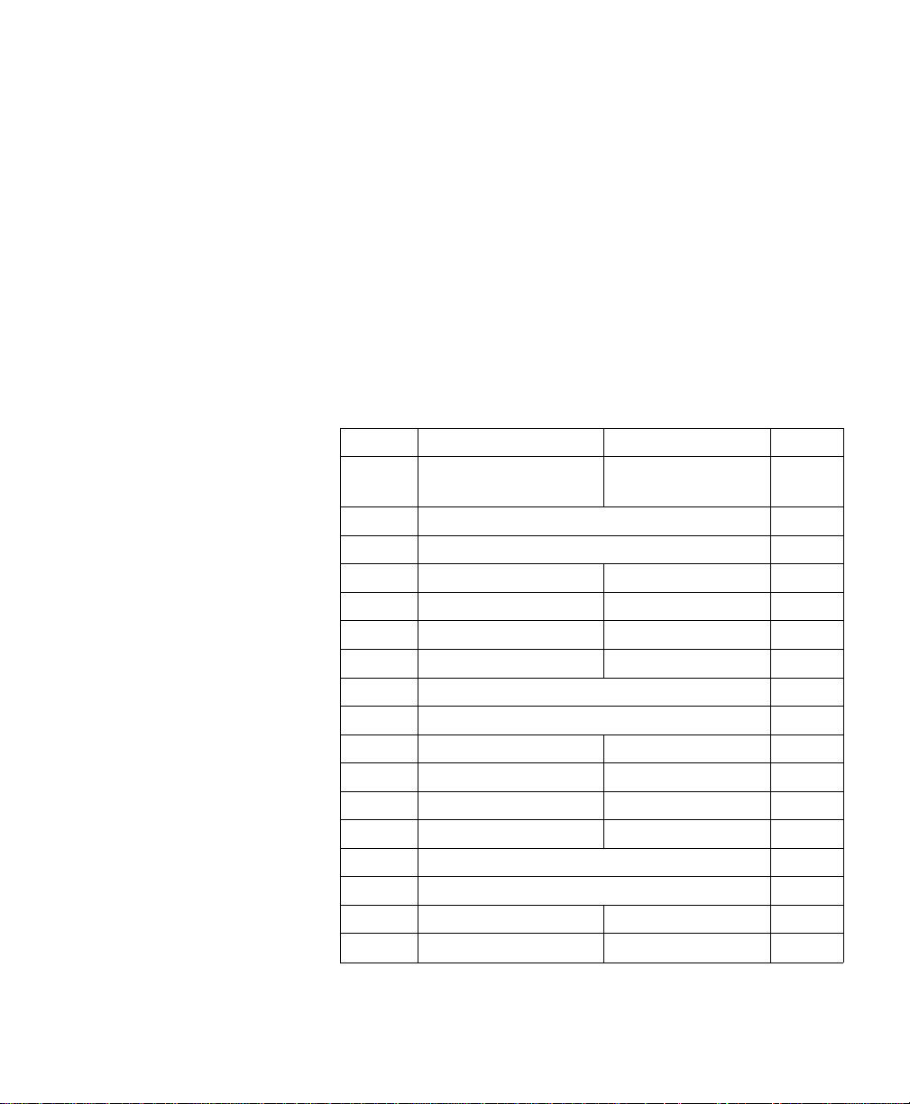
Each dither matrix must be completely specifie d.
Otherwise, the width an d heigh t values may be
misinterpreted if multiple matric es are sent.
If the width, heigh t, and data specific ation s resu lt in an odd
number data bytes, the next matrix specific ation will beg in
on an odd byte boundary. No padding is provided for
even-byte align in g .
Multiple Dither
Matr ices
As noted in the previous table, you set the number of plane s
field to 3 to send separate matrices for each primary. Each
dither matrix must have its own width and height data
fields. As shown below, the matrix specification for each
primary follows the previou s primar y colo r’s matrix
specification .
Byte 15 (msb) 8 7 (lsb) 0 Byte
0 Format = 0 Number of
planes = 3
2 Dither matrix height in pixels (uint 16) 3
4 Dither matrix width in pixels (uint 16) 5
6 byte #0 (ubyte) byte #1 (ubyte) 7
8 byte #2 (ubyte) byte #3 (ubyte) 9
•
•
n Dither matrix height in pixels (uint 16) n + 1
n+2 Dither matrix width in pixels (uint 16) n + 3
n+4 byte #0 (ubyte) byte #1 (ubyte) n + 5
n+6 byte #2 (ubyte) byte #3 (ubyte) n + 7
•
•
m Dither matrix height in pixels (uint 16) m + 1
m + 2 Dith er matr ix width in pixels (uin t 16) m + 3
m + 4 byte #0 (ubyte) byte #1 (ubyte) m + 5
m + 6 byte #2 (ubyte) byte #3 (ubyte) m + 7
1
M od ifying Output Color 4-9M od ifyin g O ut put Color 4-9
Page 82

Example This example produces a 4 x 4 dither matrix that is applied
to all three color primaries (the number of planes i s set to
1). The following command wou ld be sent to create this
dither matrix:
?*m22W010404B0B1B2B3B4 . . . B15 (where the first 6
binary bytes ar e show n as ASCII h er e for clarity, and B1 . . .
B15 indicate the binar y byte data).
The byte-aligned binary data field (shown a s ASCII for
clarity) would be:
Byte 15 (msb) 8 7 (lsb) 0 Byte
00 1 1
20 4 3
40 4 5
6B0 B1 7
8B2 B3 9
•
•
20 B14 B15 21
Note Do not use downloaded dither matr ices as patter ns since
4-10 Modifying Output Color4-10 Modifying Output Color
the orientation of the patter n will not ro tate with chan ge s
in orientation and page rotation.
Page 83

Color Lookup
T ables
Color lookup tables prov ide a way to re-map c olor data for
the following types of applications:
Highlight an d shadow modific ation
Saturation and desatu r ation
Unique gamma correction curves
Special effects for tonal correction
Neutral balancing
Color lookup tables map input data for each primary color
into a new output ran ge b ased on poin t-by -p oin t
conversions. Color look up tables can modify input data for
both device-dep en den t and dev ic e-in dependen t color spac es.
Like the CID command, the fir st byte of the data field
identifies the color spac e to which the lookup tables will be
applied. These tables specify on a point-per-p oin t basis a
transformatio n from an inpu t space of 0 . . . 255 into an
output space of 0 . . . 255. Figure 4-1 on the next page
illustrates the concept.
The unit y looku p ta ble (see the following illustration) is the
default for all color sp ace s; it perfo rms a 1:1 mapping of
input to output (that is, 129 is mapped to 129). The
inversion look up table perfo rms a simple color inversion ; for
example, it inverts the red primar y of a device-dep en den t
RGB color space to create cy an outpu t (fr om 255 red to 0
red, which is 255 cyan).
Color Lookup
Tables Command
This command enables and specifies colo r look up tables.
?*l#W[binary data]
# = Number of bytes of binar y da t a
Default = 0
Range = 0 or 770 (command is ignored for
other values; sign is ignore d)
Mod ifying Ou tp ut Color 4-11Mod ify ing Out put Col or 4-11
Page 84

A value of 0 resets or initializes the color look up tables for
each primary to the un ity c urv e (1:1). A value of 770 means
the data for a color lookup table will be following . The
command is ignored and the data is absorbed for any
number of bytes not equal to 0 or 770.
4-12 Modifying Output Color4-12 Modifying Output Color
Fig ur e 4-1. Colo r L ooku p Tab l esFig ur e 4-1. Colo r L ooku p Tab l es
Page 85

This command enables the color lookup tables un til an ?E,
Configure Image Data (CID) , or anoth er Color Lookup
T ables command with a 0 value field is received.
Note RGB gamma correction (?*t#I) and color lookup tables for
device-d epen de nt c olor spaces are mutu ally ex clusiv e and
overwrite each other.
As shown below, the 256 point-by-point transfo rmatio n
curve for each primary co lor is defined sequ en tially for a
total of 768 bytes, with the additional 2 by tes for specify in g
the color space and reser ved data field.
Byte 15 (msb) 8 7 (lsb) 0 Byte
0 Color Space Reser ved Data Field 1
2 Color Component 1, Index 1 Color Component 1, Index 2 3
4 Color Component 1, Index 3 Color Component 1, Index 4 5
. . .
256 Color Component 1, Index 255 Color Component 1, Index 256 257
258 Color Component 2, Index 1 Color Component 2, Index 2 259
260 Color Component 2, Index 3 Color Component 2, Index 4 261
. . .
512 Color Component 2, Index 255 Color Component 2, Index 256 513
514 Color Component 3, Index 1 Color Component 3, Index 2 515
516 Color Component 3, Index 3 Color Component 3, Index 4 517
. . .
768 Color Component 3, Index 255 Color Component 3, Index 256 769
Mod ifying Ou tp ut Color 4-13Mod ify ing Out put Col or 4-13
Page 86

Byte 0 (Color Space)
Value Color Space
0 Device RGB (default)
1 Device CMY
2 Colorimetric RGB Spaces
3 CIE L*a*b*
4 Luminance-Chr omin ance Spac es
A color looku p table can be attach ed to on e or more of the
color spaces anytime after a CID command . For examp le, a
Luminance- Chr omin an ce space c an have four look up tables
specified, namely:
Device-Depen dent space
CIE L*a*b* space
Colorimetric RGB space
Luminance-Chrominance space
A r eset ( ?E), IN, or CID command sets each of the four
levels of color lookup tables for eac h primar y to the unity
curve.
4-14 Modifying Output Color4-14 Modifying Output Color
Page 87

Gamma Correction Color monitors, whic h ar e by natur e non- line ar, appear
incorrect when given a linear ramp of some color. Gamma
correctio n can significantly impr ove per ceptu al co rrec tn e ss
by adjusting the brightness or darkness of the color data
sent from the monito r to any other non-lin ear device .
Gamma Correction
Command ?*t#I
# = Gamma number
Default = 0 (gamma correction off)
Range = 0.0 to 32767.0 (command is ignore d
for invalid values) *
* The practical ran ge for gamma values is 0.0
to 4.0.
Assuming 8 bits per primary (256 inten sity levels per
primary), the corr ec ted inte nsity for each color primar y is
calculated as follows:
Intensity = ( (1 + log (input / 255) ) / gamma) * 255
Gamma correction is referred to in terms of device-
dependent RGB. This command does not destroy the
content s of devic e-d epen de nt c olor looku p tables, but
setting a gamma value supercedes any looku p table inp ut
in either Device CM Y or Devic e RGB.
Note The default value (0) give s the same result as a gamma
value of 1.0, which results in a unity gamma curve.
Mod ifying Ou tp ut Color 4-15Mod ify ing Out put Col or 4-15
Page 88

Viewing
Illuminant
Printed color s und er go a hue shift wh en viewed u nd er
different illuminations (for example, fluorescent, tungsten,
or daylight). Colors with spec tral char ac teristics outside the
range of an illumin ation sour ce are no t received, chan ging
the appearan ce of mixed color s. Th e V iewing Illumin an t
command (?*i#W) supports communication of standard
illuminations to the prin ter to allow the prin ter to
compensate for differ en t ligh tin g condition s wh en
appearance match in g.
Viewing Illuminant
Command
The View ing Illuminan t co mmand specifie s the relativ e
white point used in the determination of a viewing
illuminant cond ition .
?*i#W[binary data]
# = Number of binary bytes o f da ta
Default = 8
Range = 8 (command is ignored for invalid
values; signs in the valu e field are ignor ed
The binary data field is formatted as follows:
Byte 15 (msb) 8 7 (lsb) 0 Byte
0 x chromaticity white poin t (l sw) 1
2 x chromaticity white poin t (m sw) 3
4 y chromaticity white poin t (l sw) 5
6 y chromaticity white poin t (m sw) 7
The above format adheres to the IEEE floatin g point for m at
as follows:
4-16 Modifying Output Color4-16 Modifying Output Color
31 30 23 22 0
Sign Exponent Fractional Portion
Page 89

The PCL default view in g illumin ant is D65 ( 6500K) . Below
is a table of viewing illuminants and their chr omatic ity
values.
Illuminant x chromaticity y chromaticity
Daylight (D65) (6500K) 0.3127 0.3290
T un gsten (3200K) 0.4476 0.4074
Cool White Fluorescen t
(5630K)
This command affects only devic e-in dependent colo r. The
command acts like a state variable: it is ignored for
White/Black, Dev ice RGB, or Device CMY palettes, but it
becomes active when a new CID comman d specifies a
device-in de pen den t co lor space.
0.3904 0.3914
Mod ifying Ou tp ut Color 4-17Mod ify ing Out put Col or 4-17
Page 90

Monochr o me
Printing
The Monochrome Print Mode command converts each color
value to its grayscale equ ivale nt. This impr ove s
throughpu t, costs less to print, and eliminates waste by
providing a draft mode.
Monochrome Print
Mode Command
The Monochrome Pr in t Mode command desig nate s whethe r
to print using the curren t rende ring mode or a fast
gray-scale equ ivale nt. Page s prin ted usin g the gray -sc ale
equivalen t do not use any color and th er efor e pr in t faster
and more economically.
?&b#M
# = 0 – Print in mixed ren der algorithm mode
1 – Print using gray-scale equiv alen t
Default = 0
Range = 0, 1 (command is ignored for invalid
values)
This command must be sent prior to prin table data;
otherwi se, the curr en t pag e is closed and pr in ted. It may be
sent on a page-by-page basis.
4-18 Modifying Output Color4-18 Modifying Output Color
Page 91

Driver
Configur ation
Command
device_id
function_index
This command specifies the Lig h tne ss, Saturatio n, and Scaling Algorithm to be applied to th e docu men t, an d allow s for
the selection and dow nlo adin g of Color Map s.
?*o#W[device_id function_index Arguments]
# = Specifies the number of bytes to follow
(device ID + function index + argumen t s)
Default = N/A
Range = see description below
Value Printer
6 Color LaserJet printer
function_
index
0 Lightness -100 to 100
1 Saturation -100 to 100
3 Scaling
Description Argument Range
0 Pixel Replic ation
Algorithm
1 Bilinear
2 Modified Bilinear
Mod ifying Ou tp ut Color 4-19Mod ify ing Out put Col or 4-19
Interpolation
Interpolation
Page 92

function_
index
Description Argument Range
4 Select
Color Map
5 Download
Color Map
The following parag r aph s descr ibe the fu n ct ion_inde x
values and their arg u ments.
0 No Adjustment
1 Process Blue
2 Vivid Graphics
3 Transparency
4 Out of Gamut
5 CIE Lab Match
1 CMY Color Space
3 CIELab Color Space
See Ma pID List (14739 bytes)
Lightness Negative values darken (u nlig hten ) the image, text or
graphics colo r, but do not have any effec t on black or white
data. Positive values lighte n the image. Zero tu rns the
lightness adjustment off. This function index requires three
data bytes.
Saturation Negative values desaturate (add gray to) the image, tex t or
Scaling Pixel replication is a backward-compatible scaling
4-20 Modifying Output Color4-20 Modifying Output Color
graphics colo r, but will not have any effect on black or white
data. Positive values increase th e amount of saturation ,
making the image more vivid. Z er o turn s the satur ation
adjustment off. This function index requir es thr ee data
bytes.
algorithm. Bilin ear interpolation is a hig h- quality scaling
algorithm for smo oth -edg e interpolated scaling. Modified
bilinear scaling only inter polates wh en it is best to do so.
This function index re quir es thr ee data bytes.
Page 93

Select Color Map This value specifies which co lor treatmen t mode to use for
rendering the next job.
No Adjust ment
This setting provides linearization only (that is, the user
sees the device as a linear dev ic e).
Process Blue
This setting provides the same results a s V ivid Gr aph ic s
(linearization plus user-preferred enhancements) with the
addition of mapping process blue, which looks sligh tly
purple, to a blue closer to that of a standar d monitor.
Vivid Graphics
This setting adds color satur ation to the resultin g image.
T ra n sparency
This setting uses a map to render the best color output on
transmissive media.
Out of Gamut
This setting prints colors in an imag e that are out of
gamut—all colors that ar e in gamu t snap to white, all
out-of-gamut color s are snap p ed to the gamut sur fac e. This
setting only supports the dev ic e-in de pen den t co lor map.
CIE L*a*b* Match
This map performs a true color matc h to the requested
CIE L*a*b* input (there are no appear anc e matchin g
adjustments). This setting only sup por ts the devic eindependent color map.
Note For screen matchin g , the long for m of the Config ur e Imag e
Data command is used and the color maps are generated
internally depe ndent upon the mon itor calibration data (the
Driver Configuration command is not needed).
Mod ifying Ou tp ut Color 4-21Mod ify ing Out put Col or 4-21
Page 94

Download
Color Map
The printer suppor ts the dow nloading of color adjustment
maps dependent u pon the halfton e re que ste d, the type of
color treatment desir ed (in clud ing devic e-de pen den t or
independ en t), an d the type of media.
Setting Description MapID
Device Dependen t
No
adjustment
Process Blue Cluster-Process Blue-DD 5
Transparency Cluster-Transparency-DD 9
Vivid
Graphics
Out of
Gamut
Cluster-No Adju st-DD 1
Disperse-No Adjust-D D 2
Scatter-No Adju st-DD 3
ErrorDif fusion-No Adju st-DD 4
Disperse-Process Blue-DD 6
Scatter-Pr oc es s Blue-DD 7
ErrorDiffusion-Process Blue-DD 8
Disperse-Transparency-DD 10
Scatter-Transparency-DD 11
ErrorDiffusion-Transparency-DD 12
Cluster-VividGraphics-DD 13
Disperse-VividGraphics-DD 14
Scatter-VividGraphics-DD 15
ErrorDiffusion-VividGraphics-DD 16
Cluster-OutOfGamut-DD 17
Disperse-OutOfGamut-DD 18
4-22 Modifying Output Color4-22 Modifying Output Color
Scatter-OutOfGamut-DD 19
ErrorDiffusion-OutOfGamut-DD 20
Page 95

Setting Description MapID
CIELab
Match
Device-Indep end ent
No
Adjustment
Process Blue Cluster-Process Blue-DI 55
Transparency Cluster-Transparency-DI 59
Cluster-TrueMatch-DD 21
Disperse-TrueMatch-DD 22
Scatter-TrueMatch-DD 23
ErrorDiffusion-TrueMatch-DD 24
Cluster-No Adju st-DI 51
Disperse-No Adjust-D I 52
Scatter-No Adju st-DI 53
ErrorDif fusion-No Adju st-DI 54
Disperse-Process Blue-DI 56
Scatter-Pr oc es s Blue-DI 57
ErrorDiffusion-Process Blue-DI 58
Disperse-Transparency-DI 60
Scatter-Transparency-DI 61
ErrorDiffusion-Transparency-DI 62
Vivid
Graphics
Out of
Gamut
Cluster-VividGraphics-DI 63
Disperse-VividGraphics-DI 64
Scatter-VividGraphics-DI 65
ErrorDiffusion-VividGraphics-DI 66
Cluster-OutOfGamut-DI 67
Disperse-OutOfGamut-DI 68
Scatter-OutOfGamut-DI 69
ErrorDiffusion-OutOfGamut-DI 70
Mod ifying Ou tp ut Color 4-23Mod ify ing Out put Col or 4-23
Page 96

Setting Description MapID
CIELab
Match
Cluster-TrueMatch-DI 71
Disperse-TrueMatch-DI 72
Scatter-TrueMatch-DI 73
ErrorDiffusion-TrueMatch-DI 74
4-24 Modifying Output Color4-24 Modifying Output Color
Page 97

5
The PThe PCL P rint ModelCL Print Model
Introduction The Print Model feature allow s images and char ac ter s to be
filled with color, with any of the printer’ s predefined
shading or cros s-hatch patterns, or with a user-defined
pattern. Images include any raster graph ic, such as one
created with PCL raster gr aph ics commands (as describe d
in Chapter 6, Raster Graphics); a rectangular fill area (as
described later in this chapter a s PCL Rectangular Area
Fill Graphics); or characters selec ted fr om any font.
Figure 5-1 illustrates the use of the prin t model. Th e
following defin ition s are helpfu l in desc ribin g Prin t Model
operation:
Figure 5-1.Figure 5-1. Prin t Mod e l Im agi ngPrint Model Imaging
The PCL Print Model 5-1The PCL Print Model 5-1
Page 98

Pattern—The design which is “painted” through the
non-white area of th e sour c e image onto the destination
image. The pattern is defined by the Current Patte rn
(?*v#T) command. It may be a color pattern or a
single-plan e monoc hrome mask, suc h as the printe r’s
internal pr ed efined shading or cr os s-hatch patterns, or a
user-defined pattern. Foreground color is not applied to a
user-defined color pattern.
When printin g a page, text and r aste r images are pr inte d
using the current patte rn . Once the curren t patter n is
specified, it stays in effec t un til an other is selected or the
printer is reset. A reset retur ns the c urr ent patter n to it s
default value (100% black ). The cur ren t patte rn does not
always apply to rectan gular area fill, which uses
patterns defined by th e rectan g ular area fill pattern
commands.
Fore ground Color—Foreground color is selected from
the current palette usin g the For egro und Color command
(?*v#S). Foreground color affects everything except
user-defined color patter n s an d HP-GL/2 primitiv es.
Raster color mixes with fore groun d co lor (see Chapter 6
“Color Raster Graphics”).
Texture—Textu re is anothe r name for the combinatio n
of pattern and fo re grou n d co lor, or for a color pattern
which is not combined with a for eg r ound color.
Source Image—the Source Image is an image in which
the non-white bits are replac ed by th e specif ied patter n .
The source image func tion s like a stencil th roug h whic h
the pattern is applied to the destination image . The
source image may be one of the follo wing : HP-G L/2
primitives, rules, characte rs, or raster images (single
plane mask or multi-plane color )
Destina ti on Im age— Th e image onto whic h the source
image/texture combination is placed. The destination
image includes any image s placed th ro ugh previo us
operations.
Source Transparency Mode—The transparency or
opaqueness of the source image’s “white” pixels as they
5-2 The PCL Print Model5-2 The PCL Print Model
Page 99

are applied to the destination image (se e the note below ).
Setting the source transpar en cy mode to 1 (opaque)
applies the source image’s white pixels to the destinatio n
image; with a setting of 0 (tran spar ent), th ese p ixe ls
have no effect on the destination.
Pattern Transparency Mode— The tran spar en cy or
opaqueness of the “wh ite pixe l s” in the pattern (see the
note below). When set to 0 (transpar ent), these pix el s
have no effect on the destin ation ; when set to 1 (opaque),
they are applied throu gh th e black pixels of the sour ce
pattern to the destination .
Logical Op era ti o ns —th e Pr int Model u se s logic al
operations, suc h as AND, OR, X OR, an d NO T wh en
determinin g whic h bits of the source, pattern , and
texture beco me part of th e resultin g image. The Logical
Operations command (?*l#O) can var y the log ic a l
operation used, thus varying the outcome.
Note For RGB color imag es, “w h ite” p ixe ls are those for which all
color primaries are greater than or equal to their whit e
referenc e values. For CMY color images, “wh ite” pixe l s are
those for which all color primaries ar e less than or equal to
their white reference values.
When usin g Ren der Algorithm 2 (?*t2J) for halftoning,
black pixels are affected by the tran spar en cy mode in ste ad
of white pixels.
For all renderin g algor ith m s, white dots intr odu ced in the
dithering proc ess are not sub ject to tran spar en cy modes.
Figure 5-2 illustrates the effects of the sourc e and pattern
transparenc y modes on the final image . (The transpar en c y
modes work a little differently w ith rec tang u lar area
fill—see “Pattern Transparency for Rectangu lar Are a Fill”
near the end of this chapter.)
The PCL Print Model 5-3The PCL Print Model 5-3
Page 100
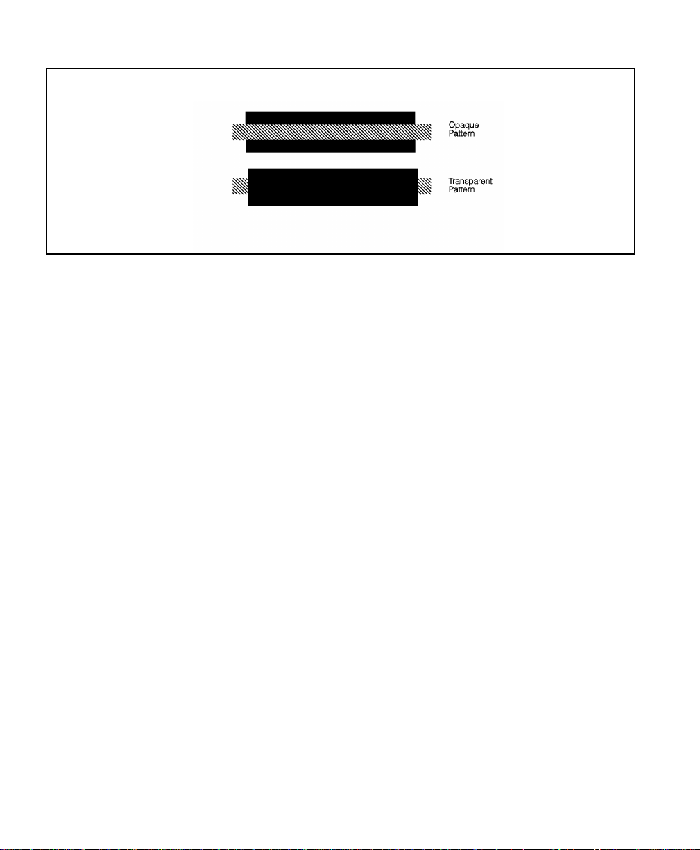
This example uses the default ROP. The output may appear differently depending on the colors used.
Figure 5-2.Fig ur e 5-2. Opaq ue an d Tr ans p ar enc y Mo d esOpaq u e an d Tr an s p ar en c y Mo d es
Figure 5-3 demonstr ates the tr anspar en cy modes. In the
first example (1a), the transparency mode for both the
source image and the patter n is transp are nt. Since the
source mode is “transpar ent,” on ly the non-w h ite re gio n
(the circle) of th e sourc e image is over laid on the
destination. Since th e patter n mode is also transparen t, the
patterned source imag e is applied only to the white areas of
the destination.
In the second example (1b), th e sour ce mode i s still
“transparent,” but the pattern mode is “opaque” – so the
pattern’ s white pix els are applie d to the destination . The
resulting image shows the entir e circ le regio n vi sible and
patterned.
In the third example (1c), the source mode is “opaque” and
the pattern mode is transpar ent. Sinc e the source mode is
opaque, the entire sour c e image (the cir cle and the
surroundin g square) appear s overlaid on to the destination .
The pattern, however, is allowed to pour through only onto
the white-pixe led are a of the destination . The circ le is
visible in the result, but only two opposing quarters appear
patterned.
In the fourth example (1d), both source and pattern modes
are “opaque.” The en tire source image is overlaid on to the
destination, and the entir e circ le is pattern ed.
5-4 The PCL Print Model5-4 The PCL Print Model
 Loading...