

Page 1

HP Pavilion HDX Entertainment Notebook PC
Maintenance and Service Guide
Page 2

© Copyright 2007 Hewlett-Packard
Development Company, L.P.
Bluetooth is a trademark owned by its
proprietor and used by Hewlett-Packard
Company under license. Intel and Core are
trademarks or registered trademarks of Intel
Corporation or its subsidiaries in the United
States and other countries. Microsoft,
Windows, and Windows Vista are either
trademarks or registered trademarks of
Microsoft Corporation in the United States
and/or other countries. SD Logo is a
trademark of its proprietor.
The information contained herein is subject to
change without notice. The only warranties
for HP products and services are set forth in
the express warranty statements
accompanying such products and services.
Nothing herein should be construed as
constituting an additional warranty. HP shall
not be liable for technical or editorial errors
or omissions contained herein.
First Edition: July 2007
Document Part Number: 443051-001
Page 3

Safety warning notice
WARNING! To reduce the possibility of heat-related injuries or of overheating the computer, do not
place the computer directly on your lap or obstruct the computer air vents. Use the computer only on a
hard, flat surface. Do not allow another hard surface, such as an adjoining optional printer, or a soft
surface, such as pillows or rugs or clothing, to block airflow. Also, do not allow the AC adapter to contact
the skin or a soft surface, such as pillows or rugs or clothing, during operation. The computer and the AC
adapter comply with the user-accessible surface temperature limits defined by the International Standard
for Safety of Information Technology Equipment (IEC 60950).
iii
Page 4

iv Safety warning notice
Page 5

Table of contents
1 Product description
2 External component identification
Top components ...................................................................................................................... 6
Display and top components ...................................................................................... 6
Top-left buttons and lights ........................................................................................... 7
Top-right buttons, lights, and fingerprint reader ............................................................. 9
TouchPad ............................................................................................................... 10
Keys ..................................................................................................................................... 11
Front components ................................................................................................................... 12
Rear components ................................................................................................................... 13
Rear left-side components ......................................................................................... 13
Rear right-side components ....................................................................................... 14
Right-side components ............................................................................................................ 15
Left-side components ............................................................................................................... 16
Bottom components ................................................................................................................ 17
3 Illustrated parts catalog
Serial number location ............................................................................................................ 18
Computer major components ................................................................................................... 19
Display assembly components ................................................................................................. 23
Plastics Kit ............................................................................................................................. 24
Mass storage devices ............................................................................................................. 25
Miscellaneous parts ................................................................................................................ 26
Sequential part number listing .................................................................................................. 27
4 Removal and replacement procedures
Preliminary replacement requirements ....................................................................................... 31
Tools required ......................................................................................................... 31
Service considerations ............................................................................................. 31
Plastic parts ............................................................................................. 31
Cables and connectors ............................................................................. 32
Drive handling ......................................................................................... 32
Grounding guidelines .............................................................................................. 33
Electrostatic discharge damage .................................................................. 33
Packaging and transporting guidelines ........................................ 34
Workstation guidelines .............................................................. 34
Equipment guidelines ................................................................. 35
v
Page 6

Unknown user password .......................................................................................... 36
Component replacement procedures ........................................................................................ 37
Serial number ......................................................................................................... 37
Battery ................................................................................................................... 38
Computer feet ......................................................................................................... 39
Display assembly internal components ....................................................................... 40
Hard drive ............................................................................................................. 45
WLAN module ........................................................................................................ 47
TV tuner module ...................................................................................................... 49
Memory module ...................................................................................................... 50
Optical drive .......................................................................................................... 52
Keyboard ............................................................................................................... 54
Hinge cover ........................................................................................................... 56
Rear cover ............................................................................................................. 57
Top cover ............................................................................................................... 59
Fingerprint reader board .......................................................................................... 61
TouchPad on/off board ........................................................................................... 62
Display assembly .................................................................................................... 64
Audio/infrared board .............................................................................................. 67
Bluetooth module .................................................................................................... 68
Front USB board ..................................................................................................... 69
Power connector LED board ..................................................................................... 70
Rear USB board ...................................................................................................... 71
Subwoofer ............................................................................................................. 72
Video connector board ............................................................................................ 73
Processor fan .......................................................................................................... 75
System board ......................................................................................................... 76
Audio connector board ............................................................................................ 80
RTC battery ............................................................................................................ 81
Processor heat sink .................................................................................................. 83
Processor ............................................................................................................... 85
Video board heat sink ............................................................................................. 87
Video board fan ..................................................................................................... 89
Video board ........................................................................................................... 90
5 Computer Setup
Starting Computer Setup ......................................................................................................... 92
Using Computer Setup ............................................................................................................ 93
Computer Setup menus ........................................................................................................... 95
vi
Changing the language of Computer Setup ................................................................ 93
Navigating and selecting in Computer Setup .............................................................. 93
Displaying system information ................................................................................... 93
Restoring default settings in Computer Setup ............................................................... 94
Closing Computer Setup .......................................................................................... 94
File menu ............................................................................................................... 95
Security menu ......................................................................................................... 96
Diagnostics menu .................................................................................................... 96
System Configuration menu ...................................................................................... 97
Page 7

6 Specifications
Computer specifications .......................................................................................................... 98
20.1-inch, WUXGA display specifications ................................................................................ 99
20.1-inch WSXGA+ display specifications .............................................................................. 100
Hard drive specifications ...................................................................................................... 101
DVD±RW and CD-RW Super Multi Double-Layer Combo Drive specifications .............................. 102
System DMA specifications .................................................................................................... 103
System interrupt specifications ............................................................................................... 104
System I/O address specifications .......................................................................................... 105
System memory map specifications ........................................................................................ 107
7 Screw listing
Phillips PM2.5×5.0 screw ..................................................................................................... 108
Black Phillips PM2.0×5.0 captive screw .................................................................................. 113
Phillips PM2.5×12.0 captive screw ........................................................................................ 114
Phillips PM3.0×4.0 screw ..................................................................................................... 115
Phillips PM2.5×8.0 screw ..................................................................................................... 116
Phillips PM2.0×3.0 screw ..................................................................................................... 118
Phillips PM3.0×8.0 screw ..................................................................................................... 119
Phillips PM2.5×4.0 screw ..................................................................................................... 121
Phillips PM3.0×12.0 screw ................................................................................................... 122
Phillips 2.5×3.0 broad-head screw ........................................................................................ 123
Phillips PM2.5×11.0 screw ................................................................................................... 124
Silver Phillips PM2.0×4.0 screw ............................................................................................ 125
Slotted SM1.5×9.0 shoulder screw ........................................................................................ 127
Phillips PM2.5×13.0 captive screw ........................................................................................ 128
Silver Phillips PM2.0×5.0 captive screw ................................................................................. 129
Phillips PM2.5×8.0 captive screw .......................................................................................... 130
Black Phillips PM2.0×4.0 screw ............................................................................................. 131
8 Backup and Recovery
Recovering system information ............................................................................................... 132
Creating recovery discs ......................................................................................... 132
Backing up your information ................................................................................... 133
When to back up ................................................................................... 133
Back up suggestions ............................................................................... 134
Using system restore points ..................................................................................... 134
When to create restore points .................................................................. 134
Create a system restore point ................................................................... 134
Restore to a previous date and time .......................................................... 136
Performing a recovery ........................................................................................... 137
Recovering from the recovery discs ........................................................... 137
Recovering from the partition on the hard drive .......................................... 137
9 Connector pin assignments
Audio-out (headphone) ......................................................................................................... 138
Audio-in (microphone) .......................................................................................................... 138
External monitor ................................................................................................................... 139
RJ-45 (network) .................................................................................................................... 140
vii
Page 8

Universal Serial Bus .............................................................................................................. 141
10 Power cord set requirements
Requirements for all countries or regions ................................................................................. 142
Requirements for specific countries or regions .......................................................................... 143
11 Recycling
Battery ................................................................................................................................ 144
Display ............................................................................................................................... 144
Index ............................................................................................................................... 150
viii
Page 9

1
Product description
Category Description
Product Name
Processors Intel® Core™ 2 Extreme processors (4-MB L2 cache, 800-MHz front side bus
X7900 2.8-GHz processor
X7800 2.6-GHz processor
T7700 2.4-GHz processor
T7500 2.2-GHz processor
T7300 2.0-GHz processor
T7100 1.8-GHz processor
System design supports up to 55-W requirement
Chipset
Southbridge: ICH8m
Graphics
Panels
Memory
Customer-accessible/upgradable
HP Pavilion HDX Entertainment Notebook PC
(FSB), 44-W):
Intel® Core™ Duo processors (4-MB L2 cache, 800-MHz FSB, 35-W):
Northbridge: Intel PM965
ATI Discrete PCI Express x 16 Graphics via MXM
20.1-inch WSXGA UltraBrightView (1680 × 1050), ~300 nits typical brightness
2 SODIMM slots
PC2-5300, 667-MHz, DDR2
Dual-channel support
Supports up to 4096 MB of system memory
4096-MB total system memory (2048 MB × 2)
●
2048-MB total system memory (1024 MB × 2)
●
1024-MB total system memory (512 MB × 2)
●
Hard drives
RAID software support not required for second hard drive
Supports all Serial ATA (SATA) 9.5-mm, 2.5-inch hard drives
1
Page 10

Category Description
Dual hard drive configurations:
400-GB, 4200-rpm (200 GB × 2)
●
320-GB, 5400-rpm (160 GB × 2)
●
280-GB, 5400-rpm (160 GB + 120 GB)
●
240-GB, 5400-rpm (120 GB + 120 MB)
●
200-GB, 7200-rpm (100 GB × 2)
●
Optical drives
Parallel ATA
Fixed (1 screw for removal)
Support for the following optical drives:
Camera
Tilt: +/- 15 degrees, with activity LED
640 × 480 by 30 frames per second
Diskette drive
Audio
10-channel, simultaneous Voice over IP (VoIP) output (V.7.1), with 95-dB signal-to-noise ratio
Dolby home theater support
12-band parametric equalizer (disabled when external connections are made)
Dynamic processing for tunable compression/limiter function
12.7-mm tray load
DVD±RW and CD-RW Super Multi Double-Layer Combo Drive with LightScribe
●
HD-DVD Drive (with read-only function)
●
Low-light VGA camera
Supports external USB drive only
HD audio: SigmaTel STAC9271D5TAyy
(SNR)
Speakers requirements:
4 speakers (40 mm × 20 mm × 10 mm dimensions)
2 speaker enclosures on the display panel, each with a 30-cc chamber
40-mm subwoofer located in base enclosure with 110-cc chamber, mechanically isolated from
V. 7.1 analog out and supported ports
Supports Microsoft Premium requirements
Pavilion-branded Altec Lansing speakers
2 omnidirectional microphones
Modem
Ethernet
Wireless
2Chapter 1 Product description
the computer with soft elastomeric grommets and foam
No integrated modem
Intel 10/100/1000 Gigabit Ethernet network interface card (NIC)
Integrated wireless local area network (WLAN) options by way of wireless module:
Page 11

Category Description
Intel PRO wireless 4965 a/b/g with 2 WLAN antennae built into the display assembly +
Intel PRO wireless 4965 a/b/g/n with 3 WLAN antennae built into the display assembly +
Intel PRO wireless 3945 a/b/g with 2 WLAN antennae built into the display assembly +
Integrated TV tuner options
Integrated analog/DVB-T TV tuner (in the rest of the world)
PAL to F-jack and infrared emitter with cable, included with TV tuner option
TV tuner antennas for both DVB-T and ATSC/NTSC
External media card
Digital Media Slot: supports SD, MMC, SD I/O, MS, MSP, xD-Picture Card; with adapter,
Ports Video ports:
VGA (Dsub 15-pin) supporting 1920 × 1200 external resolution @ 75 Hz, hot plug/unplug,
High-definition multimedia interface (HDMI) V.1.2 supporting 1080p with High-bandwidth
Bluetooth®
Bluetooth
Bluetooth
Integrated NTSC/ATSC hybrid TV tuner (in Canada and the United States)
One ExpressCard 54 slot, supports hybrid analog+ATSC and DVB-T TV tuner
supports mini versions of SD, MMC, and MS Duo (adapter is not included)
and auto-detect for correct output to wide-aspect video (disabled when connected to the HP
xb3000 Notebook Expansion Base and HP Notebook QuickDock)
Digital Content Protection (HDCP) key
Analog audio-out V.7.1
Audio-in (stereo microphone)
Audio-out (stereo headphone, 2 ports)
Center low-frequency effect (LFE) output
Front, rear, and side speaker outputs
Consumer infrared
Stereo audio input
RF input using PAL jack
S-Video capture input
Infrared emitter jack
AC power through 180-W Multipin AC adapter plug (Smart AC adapter)
Consumer infrared
eSATA
Audio ports:
TV tuner ports:
Other ports:
IEEE 1394a
RJ-45 (Ethernet, includes link and activity lights)
3
Page 12

Category Description
S-Video-out (including composite video support) via docking only
USB (4)
Remote control
Software codes for all keys follow Microsoft® Media Center requirements.
The remote control battery is customer-accessible/upgradable.
Remote control weight:
Remote control buttons:
The remote control is docked into the keyboard deck. The remote control can be ejected by
pressing the remote control eject button. The remote control can also be locked onto the
computer.
Without batteries: 41.5 to 46.5 grams
●
With batteries: 45.0 to 50.0 grams
●
MS Start (MCE green)
●
Numeric keypad (0 - 9)
●
Clear
●
Enter
●
Channel up/down
●
Volume up/down
●
Fast forward
●
Reverse
●
Play/pause
●
Previous/next track
●
● OK
Back
●
Mute
●
Guide
●
DVD player
●
TV (in the United States)/Teletext (in Europe, the Middle East, and Africa)
●
QuickPlay launch
●
Record
●
Information
●
Power
●
Music (in the United States)/R (in Europe, the Middle East, and Africa)
●
Photos (in the United States)/G (in Europe, the Middle East, and Africa)
●
4Chapter 1 Product description
Page 13

Category Description
● Video (in the United States)/Y (in Europe, the Middle East, and Africa)
Zoom (in the United States)/B (in Europe, the Middle East, and Africa)
●
Docking
Keyboard/pointing devices
Touchpad supports 2-way scrolling
Taps enabled as default
Power requirements
180-W non-PFC AC adapter with localized cable plug support (multiwire plug with ground
Security
Fingerprint reader with VeriSoft software support
Operating system Preinstalled:
Windows Vista® Ultimate (64-bit)
Windows Vista Premium (32-bit)
Serviceability End-user replaceable parts:
AC adapter
Battery (system)
Hard drives (2)
Expansion port 3 supports the HP xb3000 Notebook Expansion Base and HP Notebook
QuickDock (does not support power via dock)
14.39-inch full-size keyboard with separate numeric keypad
9-cell 2.55-Ah, 83-Wh Li-ion battery
pin, supports 2-pin DC connector)
Security cable slot
Memory module
Optical drive
WLAN module
5
Page 14
2
External component identification
Top components
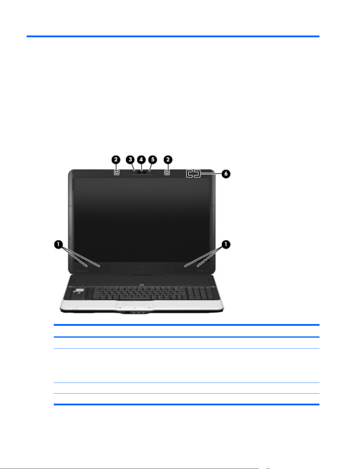
Display and top components
Item Component Description
(1)
(2)
(3)
(4)
6Chapter 2 External component identification
Speakers (4) Produce sound.
Internal microphones (2) (select models only) Record sound.
HP Webcam light On: The integrated camera is in use.
HP Webcam Records video and captures still photographs.
NOTE: If there is a microphone icon next to each
microphone opening, the computer has internal
microphones.
Page 15
Item Component Description
(5)
(6)
HP Webcam rotator Tilts the camera vertically.
Internal display switch Turns off the display if the display is closed while the computer
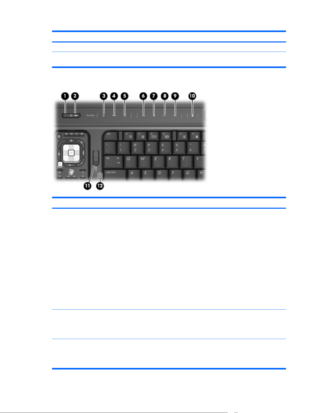
Top-left buttons and lights
is on.
Item Component Description
(1)
(2)
(3)
Power button* ● When the computer is off, press the button to turn on the
Power light
Media button
computer.
When the computer is on, press the button to initiate
●
Sleep.
When the computer is in the Sleep state, press the button
●
briefly to exit Sleep.
When the computer is in Hibernation, press the button
●
briefly to exit Hibernation.
If the computer has stopped responding and Windows®
shutdown procedures are ineffective, press and hold the
power button for at least 5 seconds to turn off the computer.
To learn more about your power settings, select Start >
Control Panel > System and Maintenance > Power
Options.
On: The computer is on.
●
Blinking: The computer is in the Sleep state.
●
Off: The computer is off or in Hibernation.
●
Opens the QuickPlay program (for models with
●
QuickPlay preinstalled).
Opens the DVDPlay program (for models with DVDPlay
●
preinstalled).
Top components 7
Page 16

Item Component Description
NOTE: If the computer has been set up to require a logon
password, you may be asked to log on to Windows.
QuickPlay or DVDPlay opens after you log on. Refer to the
QuickPlay or DVDPlay software Help for more information.
(4)
(5)
(6)
(7)
(8)
(9)
(10)
(11)
(12)
DVD button Opens the DVD playback feature of the QuickPlay program.
NOTE: If the computer has been set up to require a logon
password, you may be asked to log on to Windows.
QuickPlay opens after you log on. Refer to the QuickPlay
software Help for more information.
TV play button Opens the TV module within the QuickPlay program.
Previous/rewind button
Stop button Stops playback.
Play/pause button Plays or pauses media.
Next/fast forward button
Theater mode button Dims the lights on the computer.
Remote control button Ejects the remote control.
Caps lock light On: Caps lock is on.
Plays the previous track or chapter when the button is
●
pressed once.
Rewinds media when the button is pressed
●
simultaneously with the fn key.
Plays the next track or chapter when the button is
●
pressed once.
Fast forwards media when the button is pressed
●
simultaneously with the fn key.
*This table describes factory settings. For information about changing factory settings, refer to the user guides located in Help
and Support.
8Chapter 2 External component identification
Page 17
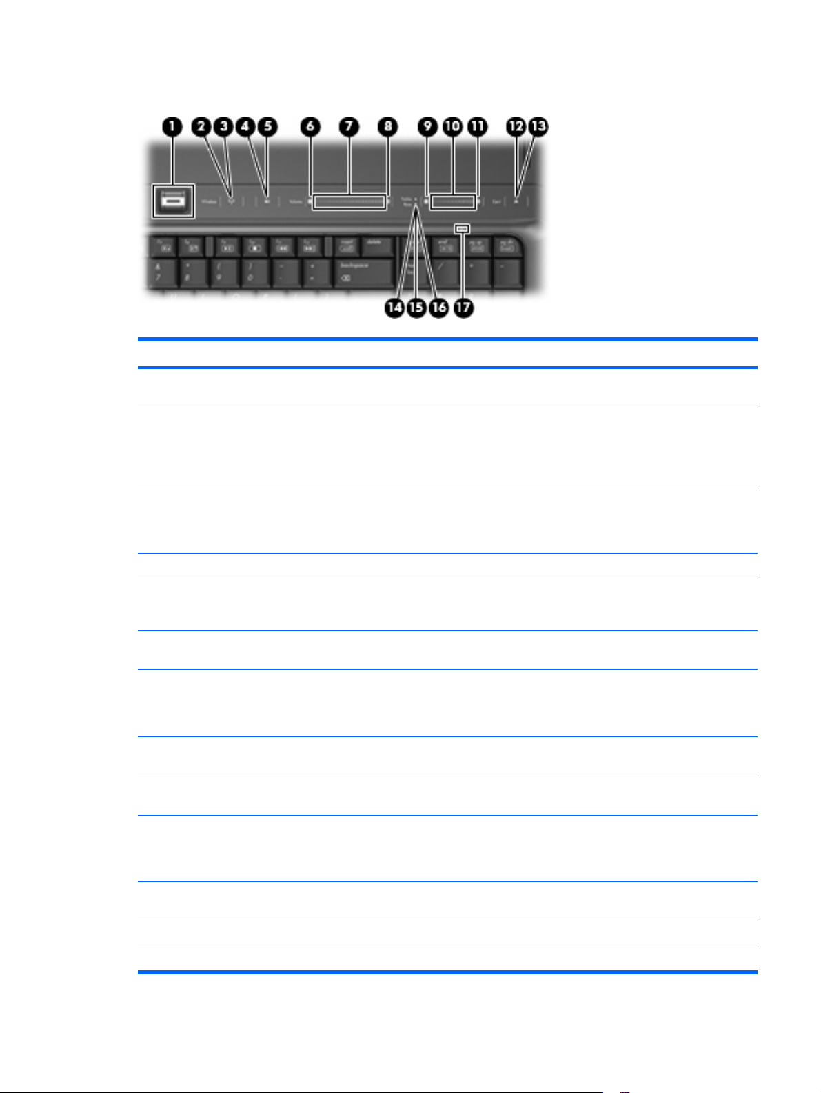
Top-right buttons, lights, and fingerprint reader
Item Component Function
(1)
(2)
(3)
(4)
(5)
(6)
(7)
(8)
Fingerprint reader Allows a fingerprint logon to Windows, instead of a
password logon.
Wireless button Turns the wireless feature on or off, but does not create a
wireless connection.
NOTE: To establish a wireless connection, a wireless
network must already be set up.
Wireless light
Volume mute button Mutes and restores speaker sound.
Volume mute light
Volume down light Blinking: The volume scroll zone is being used to decrease
Volume scroll zone Adjusts speaker volume. Slide your finger to the left to
Volume up light Blinking: The volume scroll zone is being used to increase
Blue: All integrated wireless devices, such as WLAN
●
devices and/or Bluetooth® devices, are turned on.
Amber: All integrated wireless devices are turned off.
●
Blue: Computer sound is turned on.
●
Amber: Computer sound is turned off.
●
speaker volume.
decrease volume and to the right to increase volume. You can
also tap the minus sign on the scroll zone to decrease volume,
or tap the plus sign on the scroll zone to increase volume.
speaker volume.
(9)
(10)
(11)
(12)
(13)
Treble or bass volume down light (select models only) Blinking: The volume scroll zone is being used to decrease
treble or bass volume.
Treble or bass volume scroll zone (select models only) Adjusts treble or bass volume. Slide your finger to the left to
decrease volume and to the right to increase volume. You can
also tap the minus sign on the scroll zone to decrease volume,
or tap the plus sign on the scroll zone to increase volume.
Treble or bass volume up light (select models only) Blinking: The volume scroll zone is being used to increase
treble or bass volume.
Optical drive button Releases the media tray.
Optical drive light Blinking: The optical drive is being accessed.
Top components 9
Page 18
Item Component Function
(14)
(15)
(16)
(17)
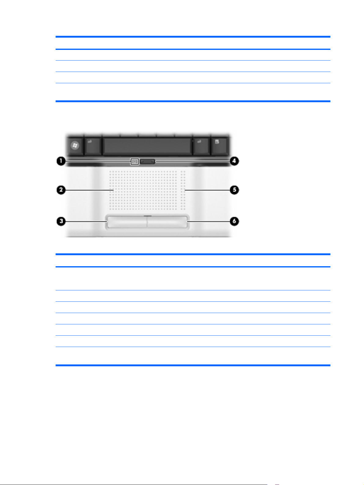
TouchPad
Treble light (select models only) On: The treble volume function is on.
Bass light (select models only) On: The bass volume function is on.
Treble/bass button (select models only) Alternates between treble and bass volume controls.
Num lock light On: Num lock is on or the embedded numeric keypad is
enabled.
Item Component Function
(1)
(2)
(3)
(4)
(5)
(6)
*This table describes factory settings. View or change pointing device preferences by selecting Start > Control Panel >
Hardware and Sound > Mouse.
TouchPad light
TouchPad* Moves the pointer and selects or activates items on the screen.
Left TouchPad button* Functions like the left button on an external mouse.
TouchPad on/off button Enables/disables the TouchPad.
TouchPad scroll zone* Scrolls up or down.
Right TouchPad button* Functions like the right button on an external mouse.
Blue: TouchPad is enabled.
●
Amber: TouchPad is disabled.
●
10 Chapter 2 External component identification
Page 19
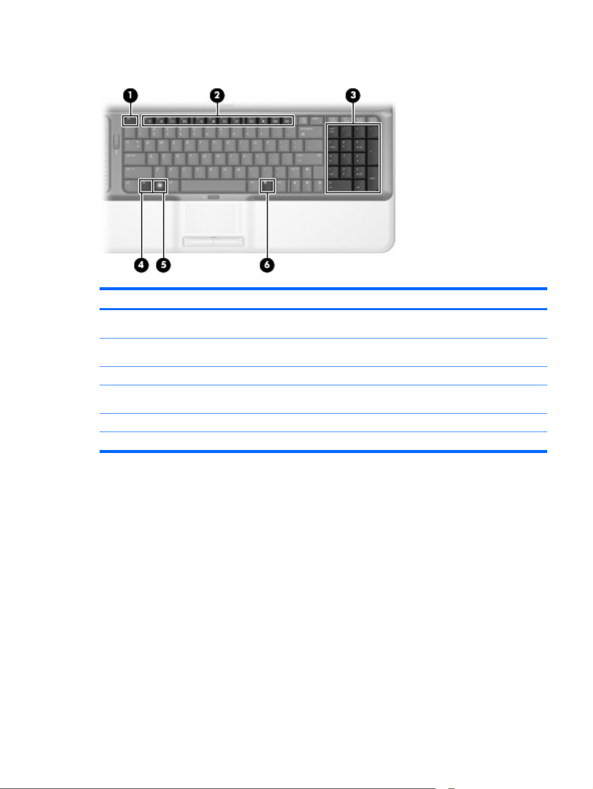
Keys
Item Component Description
(1)
(2)
(3)
(4)
(5)
(6)
esc key Displays system information when pressed in combination
with the fn key.
Function keys Execute frequently used system functions when pressed in
combination with the fn key.
Integrated numeric keypad keys Can be used like the keys on an external numeric keypad.
fn key Executes frequently used system functions when pressed in
combination with a function key or the fn key.
Windows logo key Displays the Windows Start menu.
Windows applications key Displays a shortcut menu for items beneath the pointer.
Keys 11
Page 20
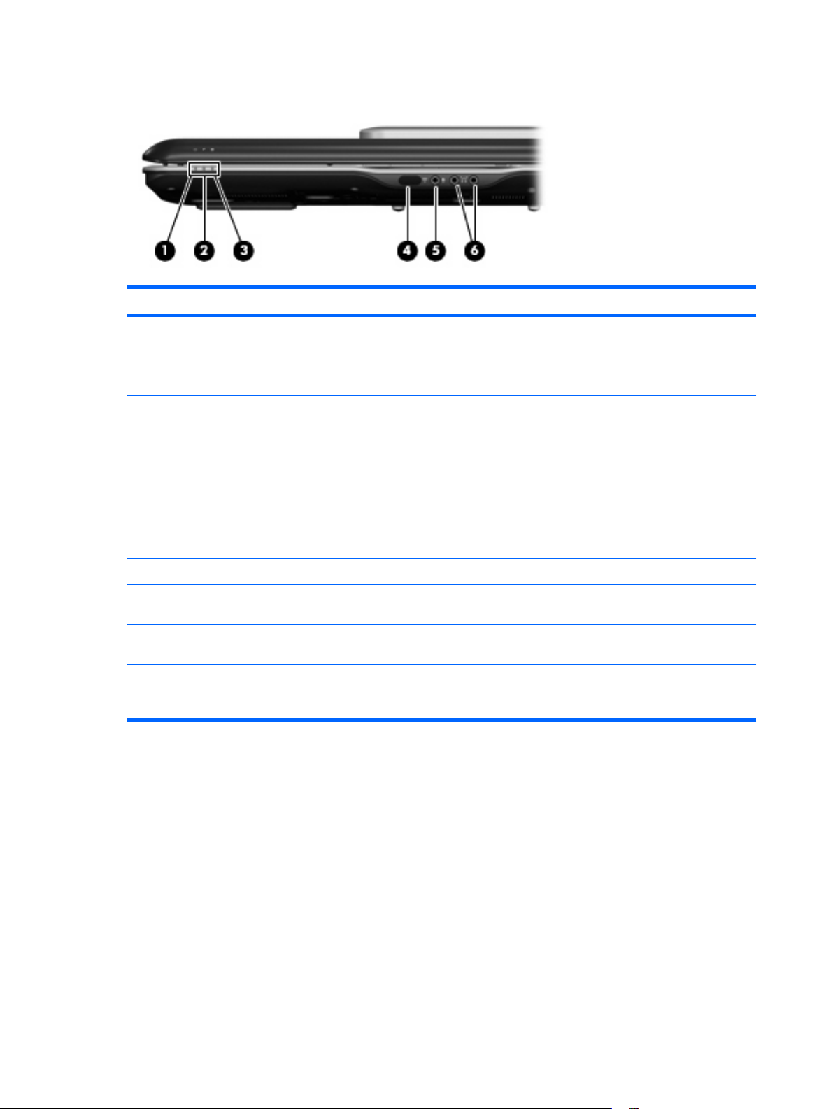
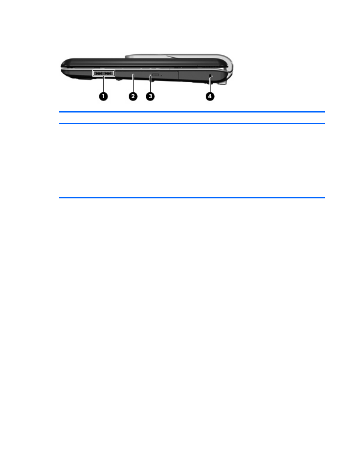
Front components
Item Component Function
(1)
(2)
(3)
(4)
(5)
(6)
Power light
Battery light
Drive light Blinking: The hard drive or optical drive is being accessed.
Consumer infrared lens Receives a signal from a remote control device, such as the
Audio-in (microphone) jack Connects an optional computer headset microphone, stereo
Audio-out (headphone) jacks (2) Produce sound when connected to optional powered stereo
On: The computer is on.
●
Blinking: The computer is in the Sleep state.
●
Off: The computer is off or in Hibernation.
●
On: A battery is charging.
●
Blinking: A battery that is the only available power
●
source has reached a low battery level or a critical
battery level.
Off: If the computer is plugged into an external power
●
source, the light is turned off when all batteries in the
computer are fully charged. If the computer is not
plugged into an external power source, the light stays
off until the battery reaches a low battery level.
HP Remote Control.
array microphone, or monaural microphone.
speakers, headphones, ear buds, a headset, or television
audio.
12 Chapter 2 External component identification
Page 21
Rear components
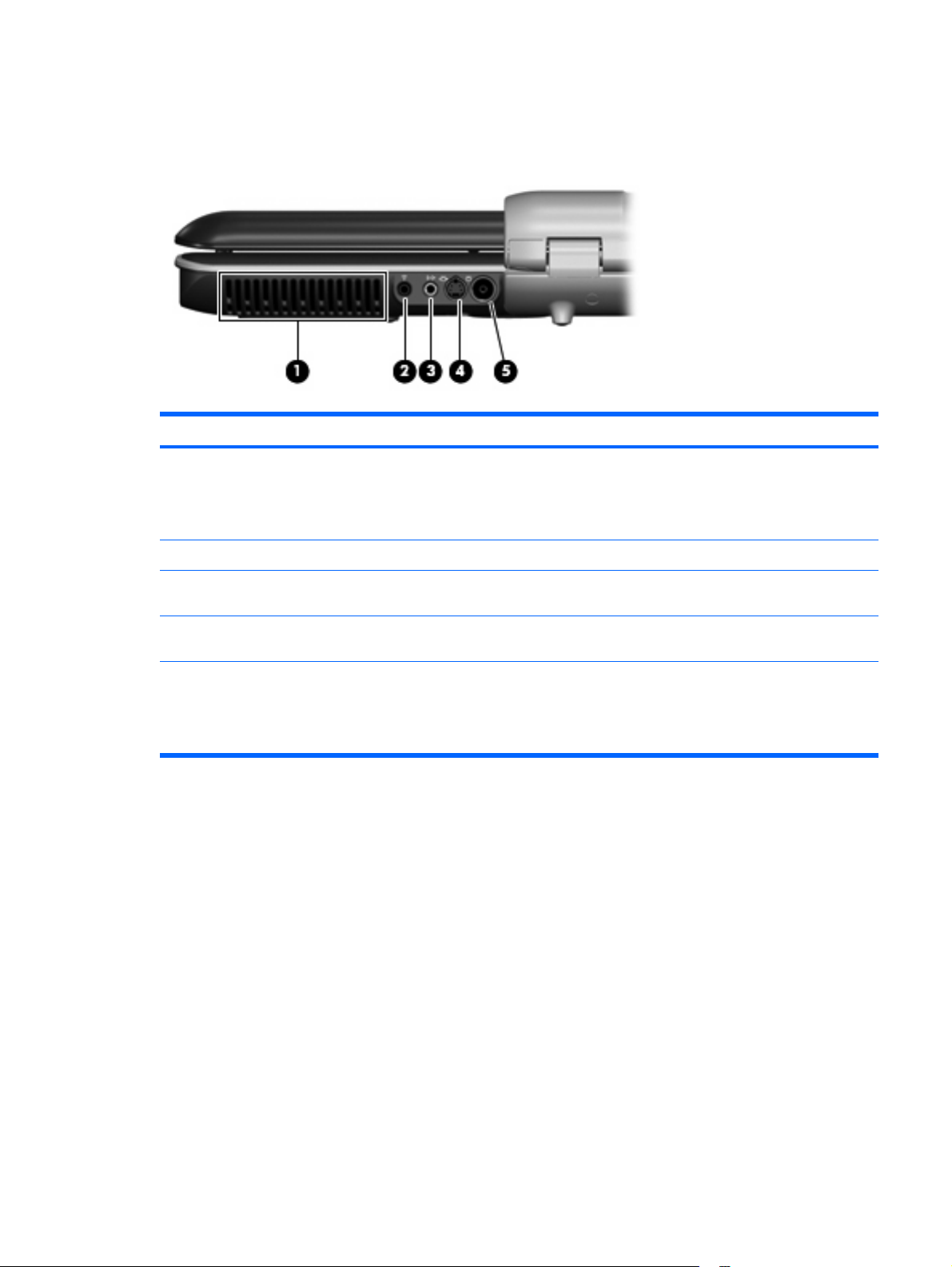
Rear left-side components
Item Component Description
(1)
(2)
(3)
(4)
(5)
Vent Enables airflow to cool internal components.
NOTE: The computer fan starts up automatically to cool
internal components and prevent overheating. It is normal for
the internal fan to cycle on and off during routine operation.
Infrared (IR) emitter jack Connects the computer to your cable or satellite set-top box.
TV audio line-in jack Connects a cable or satellite set-top box to the TV tuner for
high-quality audio.
S-Video-in jack Connects a cable or satellite set-top box to the TV tuner for
high-quality video.
RF coaxial cable jack Connects a coaxial cable or TV antenna.
NOTE: The computer is shipped with an RF coaxial cable
adapter. Depending on your computer model, the adapter
may be required for proper setup.
Rear components 13
Page 22
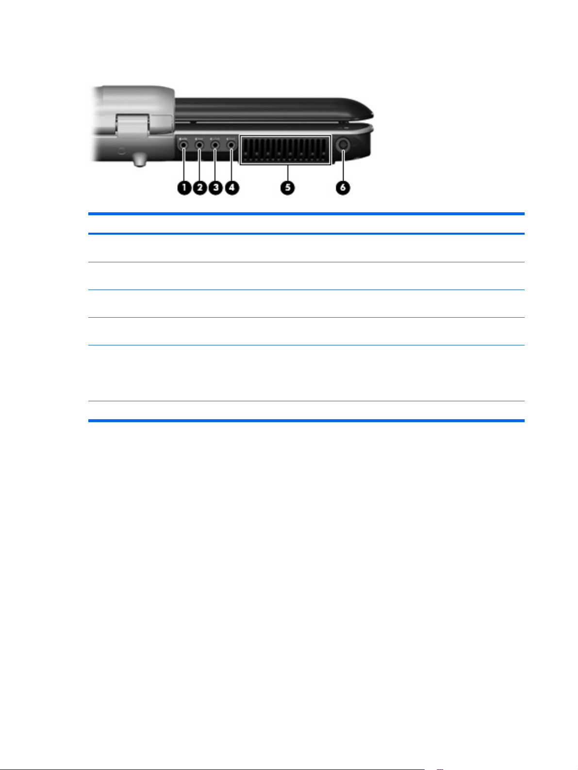
Rear right-side components
Item Component Description
(1)
(2)
(3)
(4)
(5)
(6)
Left- and right-side analog channel output jack Connects optional audio speakers for left- and right-side
audio output.
Rear left- and right-side analog channel output jack Connects optional audio speakers for rear left- and right-side
audio output.
Center channel and subwoofer analog channel output
jack
Front left- and right-side analog channel output jack Connects optional audio speakers for front left- and right-side
Vent Enables airflow to cool internal components.
Power connector Connects an AC adapter.
Connects an optional audio speaker for center channel and
subwoofer audio output.
audio output.
NOTE: The computer fan starts up automatically to cool
internal components and prevent overheating. It is normal for
the internal fan to cycle on and off during routine operation.
14 Chapter 2 External component identification
Page 23
Right-side components
Item Component Function
(1)
(2)
(3)
(4)
USB ports (2) Connect optional USB devices.
Optical drive Reads optical discs, and, on select models, also writes to
optical discs.
Optical drive light Blinking: The optical drive is being accessed.
Security cable slot Attaches an optional security cable to the computer.
NOTE: The security cable is designed to act as a
deterrent, but it may not prevent the computer from being
mishandled or stolen.
Right-side components 15
Page 24
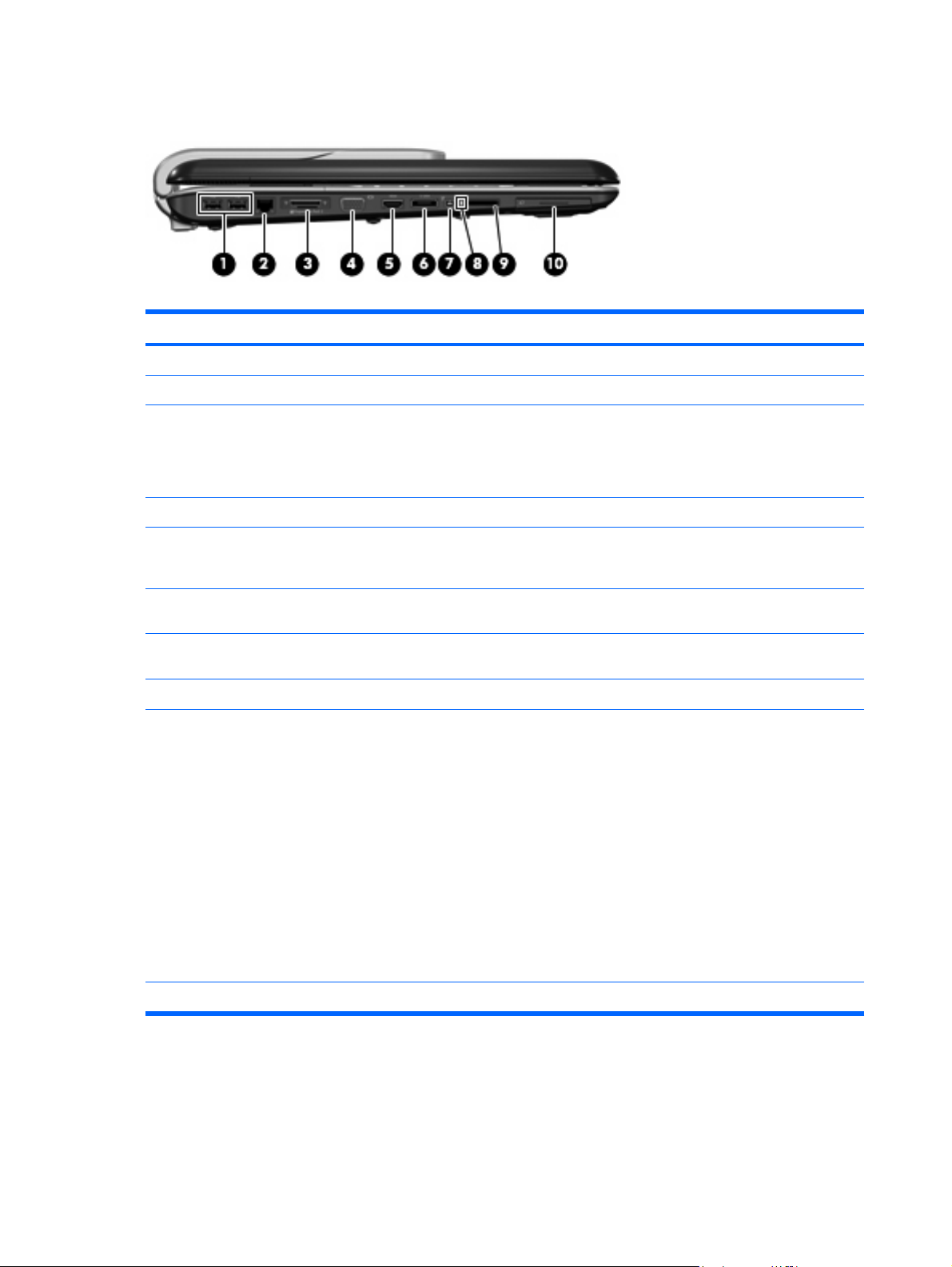
Left-side components
Item Component Function
(1)
(2)
(3)
(4)
(5)
(6)
(7)
(8)
(9)
USB ports (2) Connect optional USB devices.
RJ-45 (network) jack Connects a network cable.
Expansion port 3 Connects the computer to an optional docking device or
expansion product.
NOTE: The computer has only one expansion port. The
term expansion port 3 describes the type of expansion port.
External monitor port Connects an external VGA monitor or projector.
HDMI port (select models only) Connects an optional video or audio device, such as a high-
definition television, or any compatible digital or audio
device.
eSATA port Connects high-performance eSATA components, such as an
1394 port Connects an optional IEEE 1394 or 1394a device, such as
Digital Media Slot light On: A digital card is being accessed.
Digital Media Slot (select models only) Supports the following optional digital card formats:
eSATA external hard drive.
a camcorder.
Memory Stick (MS)
●
Memory Stick Pro (MSP)
●
MultiMediaCard (MMC)
●
(10)
ExpressCard slot Supports optional ExpressCard cards.
16 Chapter 2 External component identification
Secure Digital Input/Output (SD I/O)
●
Secure Digital (SD) Memory Card
●
xD-Picture Card (XD)
●
● xD-Picture Card (XD) Type H
xD-Picture Card (XD) Type M
●
Page 25
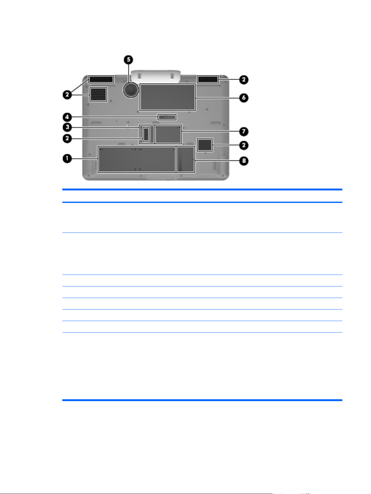
Bottom components
Item Component Function
(1)
(2)
(3)
(4)
(5)
(6)
(7)
(8)
Hard drive bay Holds the hard drives.
NOTE: Depending on the computer model, the computer
may have 1 or 2 hard drives.
Vents (5) Enable airflow to cool internal components.
NOTE: The computer fans start up automatically to cool
internal components and prevent overheating. It is normal
for the internal fans to cycle on and off during routine
operation.
TV tuner module compartment Contains the TV tuner slot.
Battery release latch Releases the battery from the battery bay.
Subwoofer Contains the subwoofer speaker.
Battery bay Holds the battery.
Memory module compartment Contains the memory module slots.
Mini Card compartment (select models only) Holds a WLAN device.
NOTE: To prevent an unresponsive system and the
display of a warning message, replace with only a Mini
Card device authorized for use in the computer by the
governmental agency that regulates wireless devices in your
country. If you replace the device and then receive a
warning message, remove the device to restore computer
functionality. Then contact technical support by selecting
Start > Help and Support > Contact support.
Bottom components 17
Page 26
3
Illustrated parts catalog
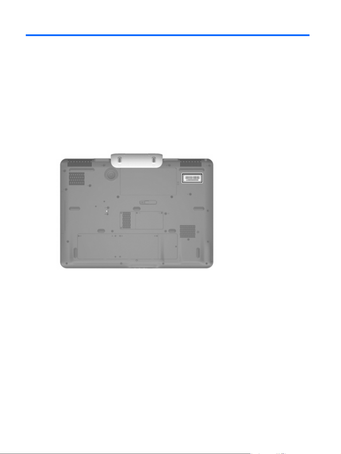
Serial number location
When ordering parts or requesting information, provide the computer serial number and model number
located on the bottom of the computer.
18 Chapter 3 Illustrated parts catalog
Page 27
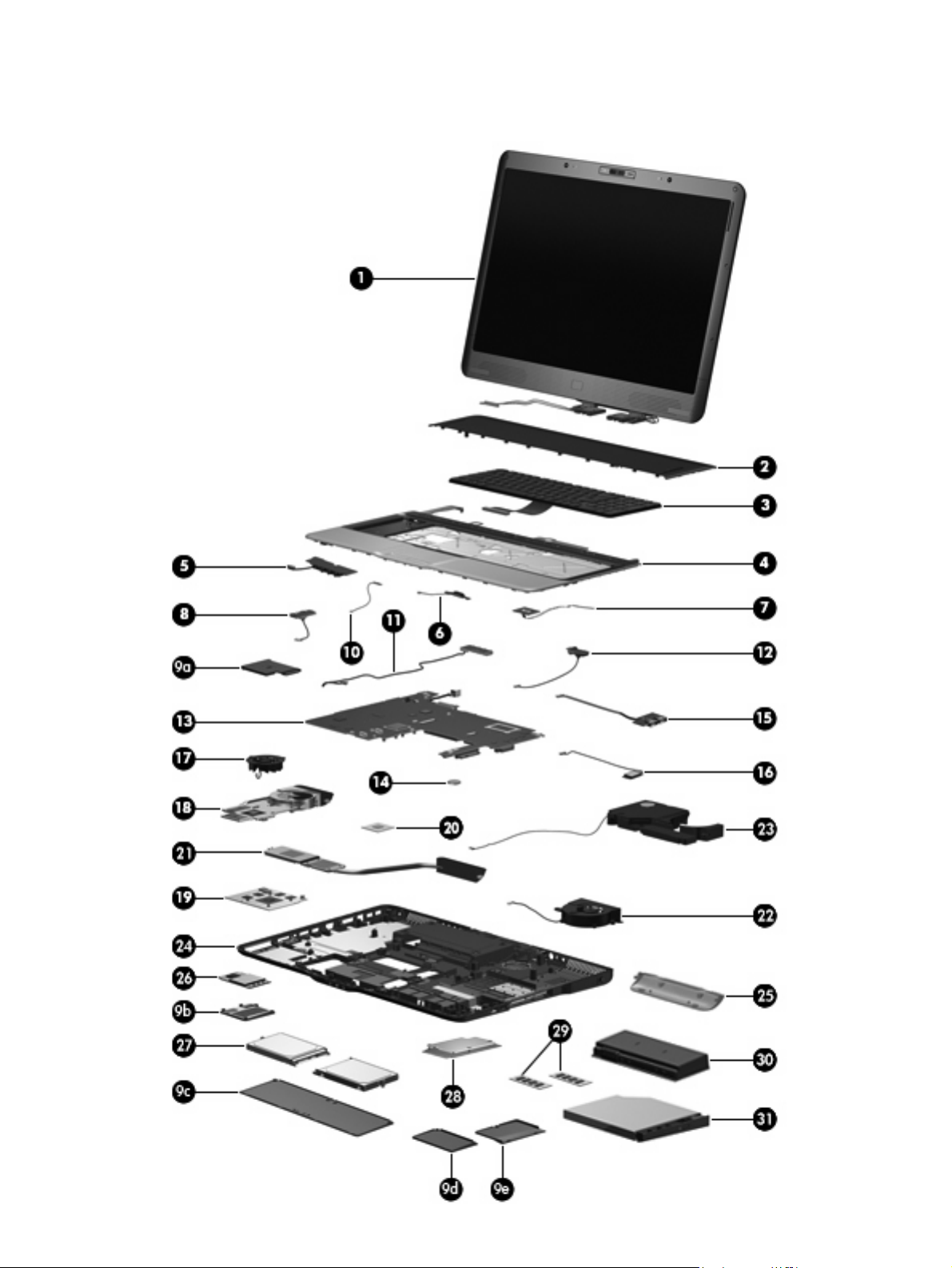
Computer major components
Computer major components 19
Page 28

Item Description Spare part number
(1) Display assemblies (include wireless antenna transceivers and cables, camera module and cable, speakers, and
microphones and cables)
20.1-inch, WUXGA, TFT 452300-001
(2)
(3) Keyboards (include keyboard cable)
For use in France 448159-051
For use in French Canada 448159-121
For use in Germany 448159-041
For use in Italy 448159-061
For use in Latin America 448159-161
For use in the Netherlands and Europe 448159-B31
For use in South Korea 448159-AD1
For use in Spain 448159-071
For use in the United Kingdom 448159-031
For use in the United States 448159-001
20.1-inch, WSXGA, TFT with BrightView 452299-001
NOTE: See Display assembly components on page 23 for more information on display assembly spare part
numbers.
Rear cover
For use in Denmark, Finland, Norway, and Sweden 448159-DH1
448161-001
(4) Top cover (includes TouchPad board cable and TouchPad button cable, and LED boards
(5) Audio/infrared board (includes cable)
(6) TouchPad on/off board (includes cable)
(7) Fingerprint reader board (includes cable)
(8) Rear USB board (includes cable)
(9a) ExpressCard slot bezel
(9b) WLAN module compartment cover
(9c) Hard drive bay cover
(9d) TV tuner module compartment cover
(9e) Memory module compartment cover
(10)
(11) Audio connector board (includes cable)
(12) Video connector board (includes cable)
(13) System board (includes power connector cable, ExpressCard assembly, and
and cables)
Plastics Kit
Power connector LED board (includes cable)
replacement thermal material)
448174-001
452316-001
448167-001
448166-001
452315-001
448171-001
452318-001
452317-001
452321-001
448145-001
20 Chapter 3 Illustrated parts catalog
Page 29

Item Description Spare part number
(14) RTC battery
(15) Front USB board (includes cable)
(16) Bluetooth module
NOTE: The Bluetooth module spare part kit does not include a Bluetooth module cable.
The Bluetooth module cable is available in the Cable Kit, spare part number 448169-001.
(17) Video board fan
(18) Video board heat sink (includes replacement thermal material)
(19) nVidia video board (includes replacement thermal material)
(20) Processors
X7800 2.6-GHz processor 455738-001 and
T7500 2.2-GHz processor 448147-001
T7300 2.0-GHz processor 448146-001
Intel Core 2 Extreme processors (4-MB L2 cache, 800-MHz FSB, 44-W):
X7900 2.8-GHz processor 453908-001
Intel Core 2 Duo processors (4-MB L2 cache, 800-MHz FSB, 35-W):
T7700 2.4-GHz processor 448148-001
452319-001
452314-001
398393-002
448163-001
448176-001
454311-001
452327-001
T7100 1.8-GHz processor 448149-001
(21) Processor heat sink (includes replacement thermal material)
(22) Processor fan
(23) Subwoofer (includes rubber isolators)
(24) Base enclosure (includes microphone and speaker extension cables and rubber feet)
(25) Hinge cover
(26) WLAN modules
Rubber Feet Kit (includes 11 computer feet in 4 sizes, and rubber screw covers)
Intel 802.11a/b/g/n WLAN modules:
For use in Antigua & Barbuda, Argentina, Aruba, the Bahamas, Barbados, Bermuda,
●
Brunei, Canada, the Cayman Islands, Chile, Colombia, Costa Rica, the Dominican
Republic, Ecuador, El Salvador, Guam, Guatemala, Haiti, Honduras, Hong Kong,
India, Indonesia, Malaysia, Mexico, Panama, Paraguay, Peru, Saudi Arabia,
Taiwan, Uruguay, the United States, Venezuela, and Vietnam
For use in Austria, Azerbaijan, Bahrain, Belgium, Brazil, Bulgaria, Croatia, Cyprus,
●
the Czech Republic, Denmark, Egypt, Estonia, Finland, France, Georgia, Germany,
Greece, Hungary, Iceland, Ireland, Israel, Italy, Latvia, Lebanon, Liechtenstein,
Lithuania, Luxembourg, Malta, Monaco, the Netherlands, Norway, Oman, the
Philippines, Poland, Portugal, Qatar, Romania, Russia, Serbia and Montenegro,
Singapore, Slovakia, Slovenia, South Africa, Spain, Sri Lanka, Sweden, Switzerland,
Turkey, Ukraine, the United Kingdom, and Uzbekistan
448175-001
448162-001
448164-001
448173-001
452320-001
452311-001
441086-001
441086-002
For use in Australia, New Zealand, Pakistan, the People's Republic of China, and
●
South Korea
441086-003
Computer major components 21
Page 30

Item Description Spare part number
(27) Hard drives (include hard drive bracket)
250-GB, 5400-rpm 454605-001
200-GB, 4200-rpm 448155-001
160-GB, 5400-rpm 448154-001
120-GB, 7200-rpm 445152-001
120-GB, 5400-rpm 448153-001
Intel 802.11a/b/g WLAN modules:
For use in Antigua & Barbuda, Argentina, Australia, the Bahamas, Barbados, Brunei,
●
Canada, Chile, the Dominican Republic, Guam, Guatemala, Hong Kong, India,
Indonesia, Malaysia, Mexico, New Zealand, Panama, Paraguay, Saudi Arabia,
Taiwan, the United States, and Vietnam
For use in Aruba, Austria, Azerbaijan, Bahrain, Belgium, Bermuda, Brazil, Bulgaria,
●
the Cayman Islands, Colombia, Croatia, Cyprus, the Czech Republic, Denmark,
Egypt, El Salvador, Estonia, Finland, France, Georgia, Germany, Greece, Hungary,
Iceland, Ireland, Italy, Jordan, Latvia, Lebanon, Liechtenstein, Lithuania, Luxembourg,
Malta, Monaco, the Netherlands, Norway, Oman, the Philippines, Poland, Portugal,
Romania, Russia, Serbia and Montenegro, Singapore, Slovakia, Slovenia, South
Africa, Spain, Sri Lanka, Sweden, Switzerland, Turkey, the United Kingdom, and
Uzbekistan
For use in Ecuador, Haiti, Honduras, Pakistan, Peru, the People's Republic of China,
●
Qatar, South Korea, Uruguay, and Venezuela
452063-001
452063-002
452063-003
100-GB, 7200-rpm 452313-001
(28) TV tuner modules
For use only in North America 448168-001
(29) Memory modules (PC2-5300, 667-MHz, DDR2)
1024-MB 448150-001
512-MB 452312-001
(30) 9-cell, 2.55-Ah, 83-Wh battery
(31) Optical drives (include bezel and bracket)
HD-DVD Drive 448156-001
For use only in Europe, the Middle East, and Africa 448168-002
2048-MB 448151-001
448158-001
DVD±RW and CD-RW Super Multi Double-Layer Combo Drive with LightScribe 448157-001
Cable Kit (not illustrated)
448169-001
22 Chapter 3 Illustrated parts catalog
Page 31

Display assembly components
Item Description Spare part number
(1) Display bezel
(2) Camera module (includes camera module brackets)
(3) Display Bracket Kit (includes left, top, and right brackets)
(4) Display panels
20.1-inch, WUXGA, TFT 452302-001
(5) Speaker Kit (includes left and right speakers)
(6) Display inverter
(7) Display hinge/enclosure (includes display panel cable and wireless antenna
20.1-inch, WSXGA+, TFT, BrightView 452301-001
cables)
452307-001
452304-001
452303-001
452310-001
452308-001
452306-001
Display assembly components 23
Page 32

Item Description Spare part number
Display Rubber Pad Kit (not illustrated)
Display Screw Kit (not illustrated)
Plastics Kit
454595-001
452309-001
Item Description Spare part number
(1)
(2)
(3)
(4)
(5)
Plastics Kit
WLAN module compartment cover (includes 1 captive screw, secured by a C-clip)
ExpressCard slot bezel
TV tuner module compartment cover (includes 1 captive screw, secured by a C-clip)
Memory module compartment cover (includes 2 captive screws, secured by C-clips)
Hard drive bay cover (includes 2 captive screws, secured by C-clips)
24 Chapter 3 Illustrated parts catalog
448171-001
Page 33

Mass storage devices
Item Description Spare part number
(1) Optical drives (include bezel and bracket)
HD-DVD Drive 448156-001
(2) Hard drives (include hard drive bracket)
200-GB, 4200-rpm 448155-001
160-GB, 5400-rpm 448154-001
120-GB, 7200-rpm 448152-001
120-GB, 5400-rpm 448153-001
100-GB, 7200-rpm 452313-001
DVD±RW and CD-RW Super Multi Double-Layer Combo Drive with LightScribe 448157-001
250-GB, 5400-rpm 454605-001
Mass storage devices 25
Page 34

Miscellaneous parts
Description Spare part number
180-W PFC AC adapter
ATSC/NTSC TV tuner antenna
ATSC/NTSC/PAL TV tuner
Bluetooth headset
Composite video cable
DVB-T tuner
DVB-T antenna adapter
ExpressCard Kit (includes software CD)
Infrared emitter with cable
Optical wired mouse
Remote controls
For use in Europe, the Middle East, and Africa
For use in North America 448165-001
RF input adapter cable (without ferrite)
USB digital drive
Wired headset
448160-001
439131-001
439130-001
443783-001
407939-001
412175-001
412176-001
445170-001
439129-001
436238-001
448165-002
407940-001
364727-002
371693-001 and
371693-003
Wireless laser mouse (includes cable adapter)
Power cords:
Australia and New Zealand 436848-011
Belgium, Europe, Finland, France, Germany, Greece, the Netherlands, Norway, Portugal, Spain, and
Sweden
Canada, French Canada, Latin America, Thailand, and the United States 436848-001
Denmark 436848-081
India 436848-D61
Italy 436848-061
South Korea 436848-AD1
The United Kingdom and Hong Kong 436848-031
Screw Kit
Phillips PM3.0×12.0 screw
●
Phillips PM3.0×8.0 screw
●
Phillips PM3.0×4.0 screw
●
Phillips PM2.5×13.0 captive screw
●
430958-001
436848-021
448172-001
26 Chapter 3 Illustrated parts catalog
Page 35

Description Spare part number
● Phillips PM2.5×12.0 captive screw
Phillips PM2.5×11.0 screw
●
Phillips PM2.5×8.0 captive screw
●
Phillips PM2.5×8.0 screw
●
Phillips PM2.5×5.0 screw
●
Phillips PM2.5×4.0 screw
●
Phillips PM2.5×3.0 broad-head screw
●
Black Phillips PM2.0×5.0 captive screw
●
Silver Phillips PM2.0×5.0 captive screw
●
Black Phillips PM2.0×4.0 screw
●
Silver Phillips PM2.0×4.0 screw
●
Phillips PM2.0×3.0 screw
●
Slotted SM1.5×9.0 shoulder screw
●
Sequential part number listing
Spare part
number
371693-001 Wired headset with volume control
371693-003 Wired headset with volume control (glossy black)
398393-002 Bluetooth module
413706-001 Thermal Material Kit
436848-001 2-wire power cord for use in the United States
436848-011 2-wire power cord for use in Australia
436848-021 2-wire power cord for use in Europe
436848-031 2-wire power cord for use in the United Kingdom
436848-061 2-wire power cord for use in Italy
436848-081 2-wire power cord for use in Denmark
436848-AD1 2-wire power cord for use in South Korea
436848-D61 2-wire power cord for use in India
Description
NOTE: The Bluetooth module spare part kit does not include a Bluetooth module cable. The Bluetooth module
cable is available in the Cable Kit, spare part number 448169-001.
441086-001 Intel 802.11a/b/g/n WLAN module for use in Antigua & Barbuda, Argentina, Aruba, the Bahamas, Barbados,
Bermuda, Brunei, Canada, the Cayman Islands, Chile, Colombia, Costa Rica, the Dominican Republic, Ecuador,
El Salvador, Guam, Guatemala, Haiti, Honduras, Hong Kong, India, Indonesia, Malaysia, Mexico, Panama,
Paraguay, Peru, Saudi Arabia, Taiwan, Uruguay, the United States, Venezuela, and Vietnam
Sequential part number listing 27
Page 36

Spare part
number
441086-002 Intel 802.11a/b/g/n WLAN module for use in Austria, Azerbaijan, Bahrain, Belgium, Brazil, Bulgaria, Croatia,
441086-003 Intel 802.11a/b/g/n WLAN module for use in Australia, New Zealand, Pakistan, the People's Republic of
443783-001 Bluetooth headset
448145-001 System board (includes power connector cable, ExpressCard assembly, and replacement thermal material)
448146-001 Intel Core 2 Duo T7300 2.0-GHz processor (includes replacement thermal material)
448147-001 Intel Core 2 Duo T7500 2.2-GHz processor (includes replacement thermal material)
448148-001 Intel Core 2 Duo T7700 2.4-GHz processor (includes replacement thermal material)
448149-001 Intel Core 2 Duo T7100 1.8-GHz processor (includes replacement thermal material)
448150-001 1024-MB memory module (PC2-5300, 667-MHz, DDR2)
448151-001 2048-MB memory module (PC2-5300, 667-MHz, DDR2)
448152-001 120-GB, 7200-rpm hard drive (includes hard drive bracket)
Description
Cyprus, the Czech Republic, Denmark, Egypt, Estonia, Finland, France, Georgia, Germany, Greece, Hungary,
Iceland, Ireland, Israel, Italy, Latvia, Lebanon, Liechtenstein, Lithuania, Luxembourg, Malta, Monaco, the
Netherlands, Norway, Oman, the Philippines, Poland, Portugal, Qatar, Romania, Russia, Serbia and
Montenegro, Singapore, Slovakia, Slovenia, South Africa, Spain, Sri Lanka, Sweden, Switzerland, Turkey,
Ukraine, the United Kingdom, and Uzbekistan
China, and South Korea
448153-001 120-GB, 5400-rpm hard drive (includes hard drive bracket)
448154-001 160-GB, 5400-rpm hard drive (includes hard drive bracket)
448155-001 200-GB, 4200-rpm hard drive (includes hard drive bracket)
448156-001 HD-DVD Drive (includes bezel and bracket)
448157-001 DVD±RW and CD-RW Super Multi Double-Layer Combo Drive with LightScribe (includes bezel and bracket)
448158-001 Battery, 9-cell, 2.55-Ah, 83-Wh
448159-001 Keyboard for use in the United States
448159-031 Keyboard for use in the United Kingdom
448159-041 Keyboard for use in France
448159-051 Keyboard for use in Germany
448159-061 Keyboard for use in Italy
448159-071 Keyboard for use in Spain
448159-121 Keyboard for use in French Canada
448159-161 Keyboard for use in Latin America
448159-AD1 Keyboard for use in South Korea
448159-B31 Keyboard for use in the Netherlands and Europe
448159-DH1 Keyboard for use in Denmark, Finland, Norway, and Sweden
448160-001 180-W AC adapter
448161-001 Rear cover
28 Chapter 3 Illustrated parts catalog
Page 37

Spare part
number
448162-001 Processor fan
448163-001 Video board fan
448164-001 Subwoofer (includes rubber isolators)
448165-001 Remote control for use in North America
448165-002 Remote control for use in Europe, the Middle East, and Africa
448166-001 Fingerprint reader board (includes cable)
448167-001 TouchPad on/off board (includes cable)
448168-001 TV tuner module for use in North America
448168-002 TV tuner module for use in Europe, the Middle East, and Africa
448169-001 Cable Kit
448171-001 Plastics Kit (see Plastics Kit on page 24 for more Plastics Kit information)
448172-001 Screw Kit
448173-001 Base enclosure (includes microphone and speaker extension cables and rubber feet)
448174-001 Top cover (includes TouchPad board cable and TouchPad button cable, and LED boards and cables)
448175-001 Processor heat sink (includes replacement thermal material)
Description
448176-001 Video board heat sink (includes replacement thermal material)
452063-001 Intel 802.11a/b/g WLAN module for use in Antigua & Barbuda, Argentina, Aruba, the Bahamas, Barbados,
452063-002 Intel 802.11a/b/g WLAN module for use in Austria, Azerbaijan, Bahrain, Belgium, Brazil, Bulgaria, Croatia,
452063-003 Intel 802.11a/b/g WLAN module for use in Australia, New Zealand, Pakistan, the People's Republic of China,
452299-001 20.1-inch, WSXGA BrightView display assembly (includes camera module and cable, microphones, speakers,
452300-001 20.1-inch, WUXGA BrightView display assembly (includes camera module and cable, microphones, speakers,
452301-001 20.1-inch, WSXGA BrightView display panel
452302-001 20.1-inch, WUXGA BrightView display panel
452303-001 Display Bracket Kit
452304-001 Camera module and camera module bracket
Bermuda, Brunei, Canada, the Cayman Islands, Chile, Colombia, Costa Rica, the Dominican Republic, Ecuador,
El Salvador, Guam, Guatemala, Haiti, Honduras, Hong Kong, India, Indonesia, Malaysia, Mexico, Panama,
Paraguay, Peru, Saudi Arabia, Taiwan, Uruguay, the United States, Venezuela, and Vietnam
Cyprus, the Czech Republic, Denmark, Egypt, Estonia, Finland, France, Georgia, Germany, Greece, Hungary,
Iceland, Ireland, Israel, Italy, Latvia, Lebanon, Liechtenstein, Lithuania, Luxembourg, Malta, Monaco, the
Netherlands, Norway, Oman, the Philippines, Poland, Portugal, Qatar, Romania, Russia, Serbia and
Montenegro, Singapore, Slovakia, Slovenia, South Africa, Spain, Sri Lanka, Sweden, Switzerland, Turkey,
Ukraine, the United Kingdom, and Uzbekistan
and South Korea
and WLAN antennae)
and WLAN antennae)
452306-001 Display hinge/enclosure (includes display cables)
452307-001 Display bezel (includes logos)
452308-001 Display inverter
Sequential part number listing 29
Page 38

Spare part
number
452309-001 Display Screw Kit
452310-001 Speaker Kit (includes left and right speakers)
452311-001 Hinge cover
452312-001 512-MB memory module (PC2-5300, 667-MHz, DDR2)
452313-001 100-GB, 7200-rpm hard drive (includes hard drive bracket)
452314-001 Front USB board (includes cable)
452315-001 Rear USB board (includes cable)
452316-001 Audio/infrared board (includes cable)
452317-001 Audio connector board (includes cable)
452318-001 Power connector LED board (includes cable)
452319-001 RTC battery
452320-001 Rubber Feet Kit (includes 11 computer feet in 4 sizes, and rubber screw covers)
452321-001 Video connector board (includes cable)
452322-001 nVidia video board (includes replacement thermal material)
452327-001 Intel Core 2 Extreme X7800 2.6-GHz processor (includes replacement thermal material)
Description
453908-001 Intel Core 2 Extreme X7900 2.8-GHz processor (includes replacement thermal material)
454311-001 nVidia video board (includes replacement thermal material)
454595-001 Display Rubber Pad Kit
454605-001 250-GB, 5400-rpm hard drive (includes hard drive bracket)
455738-001 Intel Core 2 Extreme X7800 2.6-GHz processor (includes replacement thermal material)
30 Chapter 3 Illustrated parts catalog
Page 39

4
Removal and replacement procedures
Preliminary replacement requirements
Tools required
You will need the following tools to complete the removal and replacement procedures:
Magnetic screwdriver
●
Phillips P0 and P1 screwdrivers
●
Flat-bladed screwdriver
●
Service considerations
The following sections include some of the considerations that you must keep in mind during disassembly
and assembly procedures.
NOTE: As you remove each subassembly from the computer, place the subassembly (and all
accompanying screws) away from the work area to prevent damage.
Plastic parts
Using excessive force during disassembly and reassembly can damage plastic parts. Use care when
handling the plastic parts. Apply pressure only at the points designated in the maintenance instructions.
Preliminary replacement requirements 31
Page 40

Cables and connectors
CAUTION: When servicing the computer, be sure that cables are placed in their proper locations
during the reassembly process. Improper cable placement can damage the computer.
Cables must be handled with extreme care to avoid damage. Apply only the tension required to unseat
or seat the cables during removal and insertion. Handle cables by the connector whenever possible. In
all cases, avoid bending, twisting, or tearing cables. Be sure that cables are routed in such a way that
they cannot be caught or snagged by parts being removed or replaced. Handle flex cables with extreme
care; these cables tear easily.
Drive handling
CAUTION: Drives are fragile components that must be handled with care. To prevent damage to the
computer, damage to a drive, or loss of information, observe these precautions:
Before removing or inserting a hard drive, shut down the computer. If you are unsure whether the computer
is off or in Hibernation, turn the computer on, and then shut it down through the operating system.
Before handling a drive, be sure that you are discharged of static electricity. While handling a drive,
avoid touching the connector.
Before removing a diskette drive or optical drive, be sure that a diskette or disc is not in the drive and be
sure that the optical drive tray is closed.
Handle drives on surfaces covered with at least one inch of shock-proof foam.
Avoid dropping drives from any height onto any surface.
After removing a hard drive, an optical drive, or a diskette drive, place it in a static-proof bag.
Avoid exposing a hard drive to products that have magnetic fields, such as monitors or speakers.
Avoid exposing a drive to temperature extremes or liquids.
If a drive must be mailed, place the drive in a bubble pack mailer or other suitable form of protective
packaging and label the package “FRAGILE.”
32 Chapter 4 Removal and replacement procedures
Page 41

Grounding guidelines
Electrostatic discharge damage
Electronic components are sensitive to electrostatic discharge (ESD). Circuitry design and structure
determine the degree of sensitivity. Networks built into many integrated circuits provide some protection,
but in many cases, ESD contains enough power to alter device parameters or melt silicon junctions.
A discharge of static electricity from a finger or other conductor can destroy static-sensitive devices or
microcircuitry. Even if the spark is neither felt nor heard, damage may have occurred.
An electronic device exposed to ESD may not be affected at all and can work perfectly throughout a
normal cycle. Or the device may function normally for a while, then degrade in the internal layers,
reducing its life expectancy.
CAUTION: To prevent damage to the computer when you are removing or installing internal
components, observe these precautions:
Keep components in their electrostatic-safe containers until you area ready to install them.
Use nonmagnetic tools.
Before touching an electronic component, discharge static electricity by using the guidelines described in
this section.
Avoid touching pins, leads, and circuitry. Handle electronic components as little as possible.
If you remove a component, place it in an electrostatic-safe container.
The following table shows how humidity affects the electrostatic voltage levels generated by different
activities.
CAUTION: A product can be degraded by as little as 700 V.
Typical electrostatic voltage levels
Relative humidity
Event 10% 40% 55%
Walking across carpet 35,000 V 15,000 V 7,500 V
Walking across vinyl floor 12,000 V 5,000 V 3,000 V
Motions of bench worker 6,000 V 800 V 400 V
Removing DIPS from plastic tube 2,000 V 700 V 400 V
Removing DIPS from vinyl tray 11,500 V 4,000 V 2,000 V
Removing DIPS from Styrofoam 14,500 V 5,000 V 3,500 V
Removing bubble pack from PCB 26,500 V 20,000 V 7,000 V
Packing PCBs in foam-lined box 21,000 V 11,000 V 5,000 V
Preliminary replacement requirements 33
Page 42

Packaging and transporting guidelines
Follow these grounding guidelines when packaging and transporting equipment:
To avoid hand contact, transport products in static-safe tubes, bags, or boxes.
●
Protect ESD-sensitive parts and assemblies with conductive or approved containers or packaging.
●
Keep ESD-sensitive parts in their containers until the parts arrive at static-free workstations.
●
Place items on a grounded surface before removing items from their containers.
●
Always be properly grounded when touching a component or assembly.
●
Store reusable ESD-sensitive parts from assemblies in protective packaging or nonconductive foam.
●
Use transporters and conveyors made of antistatic belts and roller bushings. Be sure that mechanized
●
equipment used for moving materials is wired to ground and that proper materials are selected to
avoid static charging. When grounding is not possible, use an ionizer to dissipate electric charges.
Workstation guidelines
Follow these grounding workstation guidelines:
Cover the workstation with approved static-shielding material.
●
Use a wrist strap connected to a properly grounded work surface and use properly grounded tools
●
and equipment.
Use conductive field service tools, such as cutters, screwdrivers, and vacuums.
●
When fixtures must directly contact dissipative surfaces, use fixtures made only of static-safe
●
materials.
Keep the work area free of nonconductive materials, such as ordinary plastic assembly aids and
●
Styrofoam.
Handle ESD-sensitive components, parts, and assemblies by the case or PCM laminate. Handle these
●
items only at static-free workstations.
Avoid contact with pins, leads, or circuitry.
●
Turn off power and input signals before inserting or removing connectors or test equipment.
●
34 Chapter 4 Removal and replacement procedures
Page 43

Equipment guidelines
Grounding equipment must include either a wrist strap or a foot strap at a grounded workstation.
When seated, wear a wrist strap connected to a grounded system. Wrist straps are flexible straps
●
with a minimum of one megohm ±10% resistance in the ground cords. To provide proper ground,
wear a strap snugly against the skin at all times. On grounded mats with banana-plug connectors,
use alligator clips to connect a wrist strap.
When standing, use foot straps and a grounded floor mat. Foot straps (heel, toe, or boot straps) can
●
be used at standing workstations and are compatible with most types of shoes or boots. On
conductive floors or dissipative floor mats, use foot straps on both feet with a minimum of one megohm
resistance between the operator and ground. To be effective, the conductive strips must be worn in
contact with the skin.
The following grounding equipment is recommended to prevent electrostatic damage:
Antistatic tape
●
Antistatic smocks, aprons, and sleeve protectors
●
Conductive bins and other assembly or soldering aids
●
Nonconductive foam
●
Conductive tabletop workstations with ground cords of one megohm resistance
●
Static-dissipative tables or floor mats with hard ties to the ground
●
Field service kits
●
Static awareness labels
●
Material-handling packages
●
Nonconductive plastic bags, tubes, or boxes
●
Metal tote boxes
●
Electrostatic voltage levels and protective materials
●
The following table lists the shielding protection provided by antistatic bags and floor mats.
Material Use Voltage protection level
Antistatic plastic Bags 1,500 V
Carbon-loaded plastic Floor mats 7,500 V
Metallized laminate Floor mats 5,000 V
Preliminary replacement requirements 35
Page 44

Unknown user password
If the computer you are servicing has an unknown user password, follow these steps to clear the password.
NOTE: These steps also clear CMOS.
Before disassembling the computer, follow these steps:
Shut down the computer. If you are unsure whether the computer is off or in Hibernation, turn the
1.
computer on, and then shut it down through the operating system.
Disconnect all external devices connected to the computer.
2.
Disconnect the power from the computer by first unplugging the power cord from the AC outlet and
3.
then unplugging the AC adapter from the computer.
Remove the battery (see
4.
Remove the RTC battery (see
5.
Wait approximately 5 minutes.
6.
Replace the RTC battery and reassemble the computer.
7.
Connect AC power to the computer. Do not reinsert any batteries at this time.
8.
Turn on the computer.
9.
All passwords and all CMOS settings have been cleared.
Battery on page 38).
RTC battery on page 81).
36 Chapter 4 Removal and replacement procedures
Page 45

Component replacement procedures
This chapter provides removal and replacement procedures.
There are as many as 154 screws, in 18 different sizes, that must be removed, replaced, or loosened
when servicing the computer. Make special note of each screw size and location during removal and
replacement.
Serial number
Report the computer serial number to HP when requesting information or ordering spare parts. The serial
number is located on the bottom of the computer.
Component replacement procedures 37
Page 46

Battery
Description Spare part number
9-cell, 2.55-Ah, 83-Wh battery 448158-001
Before disassembling the computer, follow these steps:
Shut down the computer. If you are unsure whether the computer is off or in Hibernation, turn the
1.
computer on, and then shut it down through the operating system.
Disconnect all external devices connected to the computer.
2.
Disconnect the power from the computer by first unplugging the power cord from the AC outlet and
3.
then unplugging the AC adapter from the computer.
Remove the battery:
Turn the computer upside down on a flat surface.
1.
2. Slide the battery release latch (1) to release the battery.
3. Pivot the battery (2) upward and remove it from the computer (3).
To insert the battery, insert the rear edge of the battery into the battery bay and pivot the front edge of
the battery downward until it is seated. The battery release latch automatically locks the battery into place.
38 Chapter 4 Removal and replacement procedures
Page 47
Computer feet
Description Spare part number
Rubber Feet Kit (includes 11 computer feet in 4 sizes) 452320-001
The computer feet are adhesive-backed rubber pads. The feet attach to the base enclosure in the locations
illustrated below.
Component replacement procedures 39
Page 48

Display assembly internal components
NOTE: If it has been determined that the display bezel, camera module, display inverter, display panel,
or speakers are the components that must be replaced to complete the computer repair, the display
assembly does not have to be completely removed from the computer. Replacement of these components
can be completed by removing only the display bezel. Follow the procedures in this section to replace
the display bezel, camera module, display inverter, display panel, or speakers. For information on
replacing the entire display assembly, see
Before removing the display bezel, follow these steps:
Shut down the computer. If you are unsure whether the computer is off or in Hibernation, turn the
1.
computer on, and then shut it down through the operating system.
Disconnect all external devices connected to the computer.
2.
Disconnect the power from the computer by first unplugging the power cord from the AC outlet and
3.
then unplugging the AC adapter from the computer.
Display assembly on page 64.
Remove the battery (see
4.
Remove the display bezel:
Turn the computer display-side up, with the rear panel toward you.
1.
Open the computer as far as possible.
2.
3. Remove the two rubber screw covers from the back of the display assembly (1). All rubber screw
covers and logo labels removed in this section are included in the Display Rubber Pad Kit, spare part
number 454595-001.
4. Remove the two Phillips 2.5×5.0 screws (2) that secure the display bezel to the display enclosure.
Battery on page 38).
Position the computer with the front toward you.
5.
40 Chapter 4 Removal and replacement procedures
Page 49

Remove the following screw covers and logo labels:
6.
(1) Two rubber screw covers on the display bezel top edge corners
(2) Two rubber screw covers on the display bezel top edge
(3) Four rubber screw covers on the display bezel left and right sides
(4) Speaker logo label on the display bezel lower left edge
(5) Computer model logo label on the display bezel lower right edge
Remove the ten Phillips PM2.5×5.0 screws that secure the display bezel to the display assembly.
7.
8. Flex the inside edges of the left and right sides (1) and the top and bottom edges (2) of the display
bezel until the bezel disengages from the display enclosure.
Component replacement procedures 41
Page 50
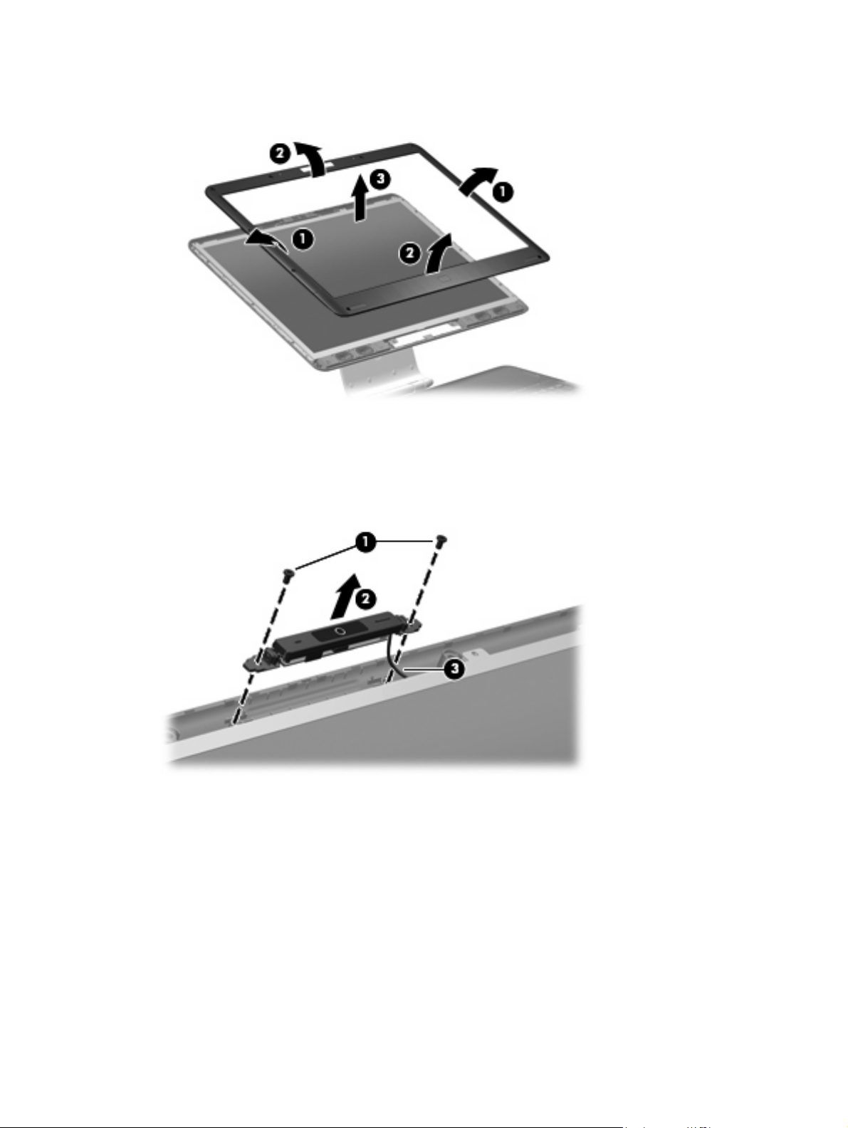
9. Remove the display bezel (3). The display bezel is available using spare part number
452307-001.
10. If it is necessary to replace the camera module, remove the two Phillips PM2.5×5.0 screws (1) that
secure the camera module to the display enclosure.
11. Release the camera module (2) from the display enclosure as far as the camera module cable allows.
12. Disconnect the camera module cable (3) from the camera module.
Remove the camera module. The camera module is available using spare part number
13.
452304-001.
14. If it is necessary to replace the display inverter, remove the display inverter (1) from the display
enclosure as far as the two display inverter cables and the backlight cable allow.
42 Chapter 4 Removal and replacement procedures
Page 51
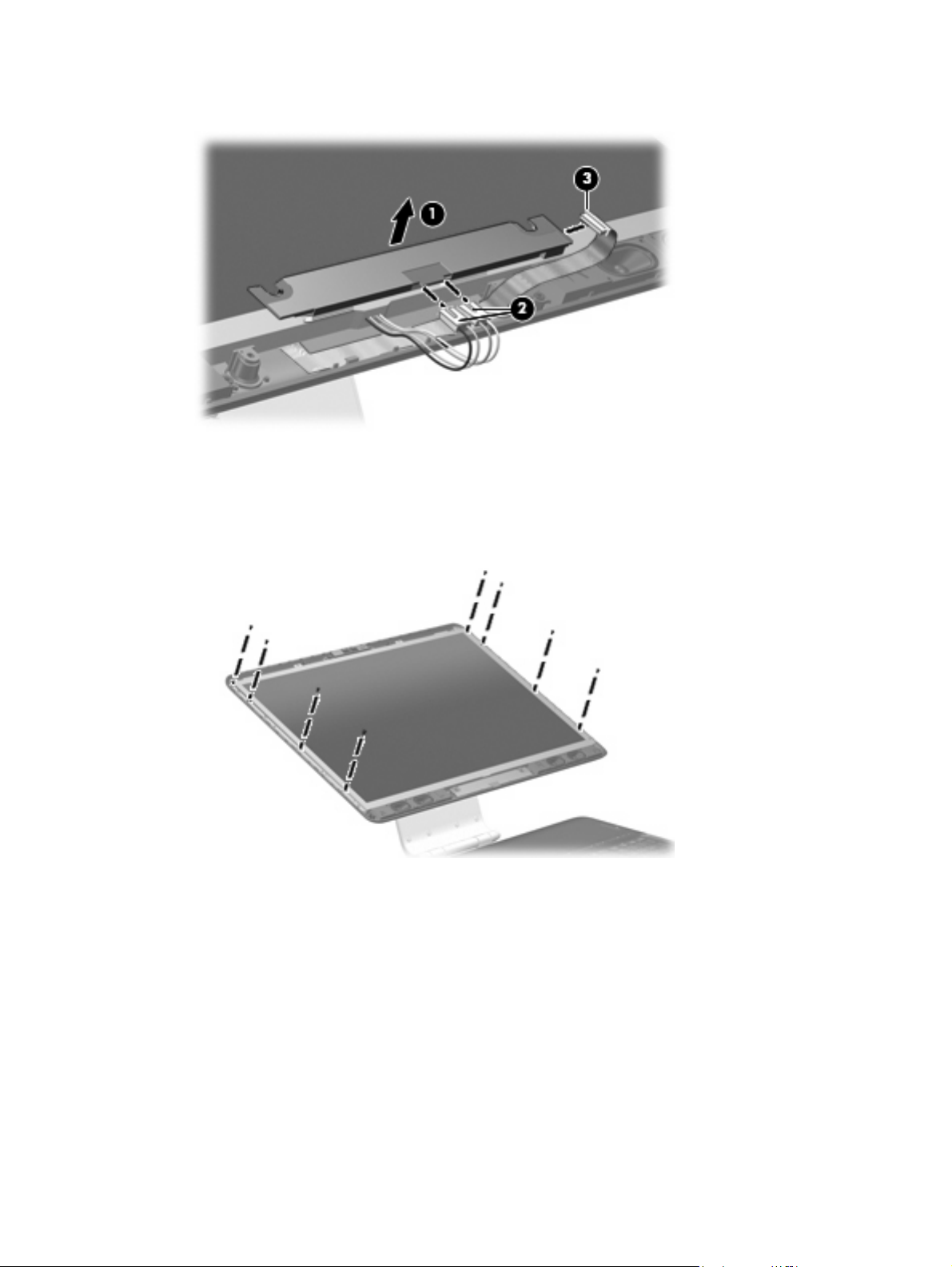
15. Disconnect the two display panel cables (2) and the backlight cable (3) from the display inverter.
Remove the display inverter. The display inverter is available using spare part number
16.
452308-001.
If it is necessary to rep lace the display panel, remove the eight Phillips PM2.5×5.0 screws that secure
17.
the display panel to the display enclosure.
18. Tilt the top edge of the display panel (1) forward until the display panel cable connector is accessible.
Component replacement procedures 43
Page 52

19. Squeeze the tabs on the display panel cable connector (2) together and disconnect the cable (3)
from the display panel.
Remove the display panel. The display panel is available using spare part numbers 452301-001
20.
(20.1-inch, WSXGA+BrightView) and 452302-001 (20.1-inch, WUXGA).
21. If it is necessary to replace the speakers, disconnect the speaker cable connectors (1) from the
speaker extension cable connectors.
22. Remove the two Phillips PM2.5×5.0 screws (2) that secure each speaker to the display enclosure.
23. Remove the speakers (3). The speakers are available using spare part number 452310-001
Reverse this procedure to install the display bezel, camera module, display inverter, display panel, and
speakers.
44 Chapter 4 Removal and replacement procedures
Page 53

Hard drive
NOTE: All hard drive spare part kits include a hard drive bracket.
Description Spare part number
250-GB, 5400-rpm 454605-001
200-GB, 4200-rpm 448155-001
160-GB, 5400-rpm 448154-001
120-GB, 7200-rpm 448152-001
120-GB, 5400-rpm 448153-001
100-GB, 7200-rpm 452313-001
Before removing the hard drive, follow these steps:
Shut down the computer. If you are unsure whether the computer is off or in Hibernation, turn the
1.
computer on, and then shut it down through the operating system.
Disconnect all external devices connected to the computer.
2.
Disconnect the power from the computer by first unplugging the power cord from the AC outlet and
3.
then unplugging the AC adapter from the computer.
Remove the battery (see
4.
Battery on page 38).
Remove the hard drive:
1. Loosen the six black Phillips PM2.0×5.0 captive screws (1) that secure the hard drive bay cover to
the computer.
2. Lift the rear edge of the hard drive bay cover (2), swing it forward, and remove the cover. The hard
drive bay cover is included in the Plastics Kit, spare part number 448171-001.
3. Loosen the Phillips PM2.5×12.0 screw (1) that secures each hard drive to the computer.
4. Disconnect the hard drives (2) from the system board by sliding the hard drives away from the hard
drive connectors.
Component replacement procedures 45
Page 54
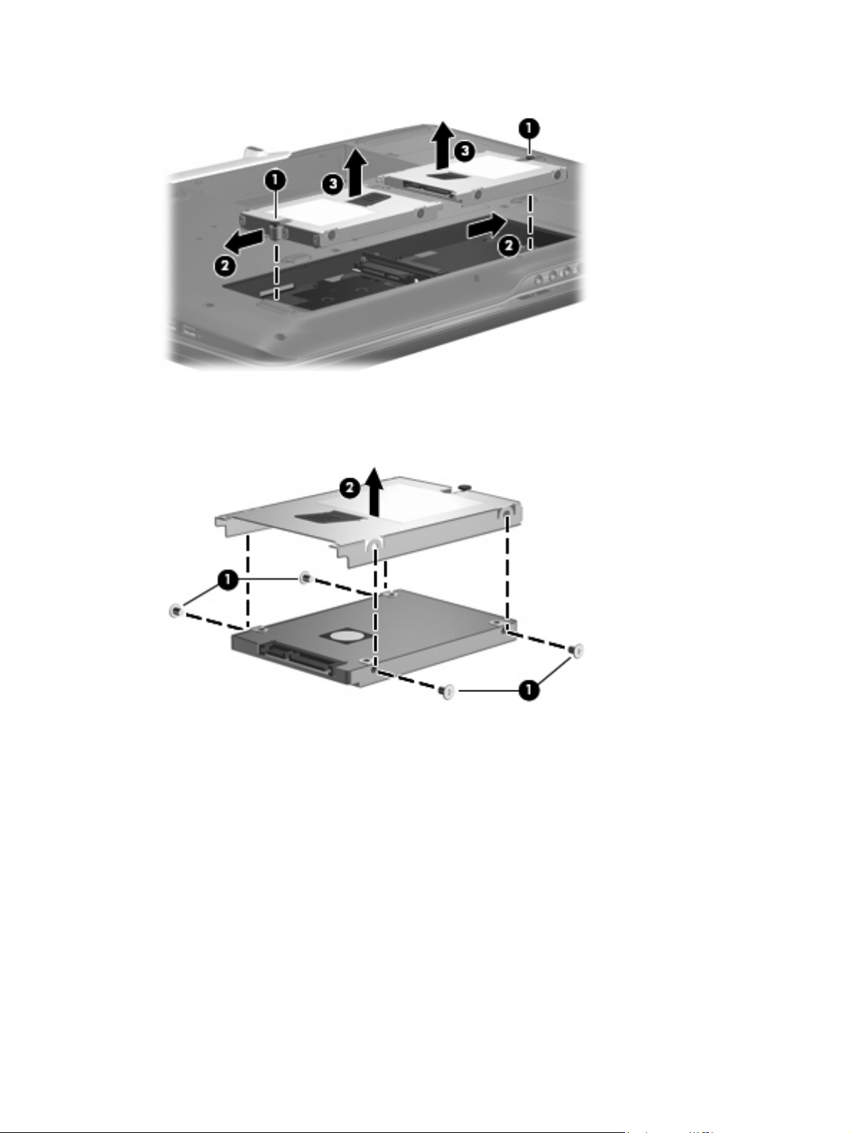
5. Remove the hard drives (3) from the hard drive compartments.
6. If it is necessary to replace the hard drive bracket, remove the four Phillips PM3.0×4.0 screws (1)
that secure the hard drive bracket to the hard drive.
7. Lift the bracket (2) straight up to remove it from the hard drive.
Reverse this procedure to reassemble and install the hard drive.
46 Chapter 4 Removal and replacement procedures
Page 55

WLAN module
Description Spare part number
Intel 802.11a/b/g/n WLAN modules:
For use in Antigua & Barbuda, Argentina, Aruba, the Bahamas, Barbados, Bermuda, Brunei,
●
Canada, the Cayman Islands, Chile, Colombia, Costa Rica, the Dominican Republic, Ecuador,
El Salvador, Guam, Guatemala, Haiti, Honduras, Hong Kong, India, Indonesia, Malaysia,
Mexico, Panama, Paraguay, Peru, Saudi Arabia, Taiwan, Uruguay, the United States,
Venezuela, and Vietnam
For use in Austria, Azerbaijan, Bahrain, Belgium, Brazil, Bulgaria, Croatia, Cyprus, the Czech
●
Republic, Denmark, Egypt, Estonia, Finland, France, Georgia, Germany, Greece, Hungary,
Iceland, Ireland, Israel, Italy, Latvia, Lebanon, Liechtenstein, Lithuania, Luxembourg, Malta,
Monaco, the Netherlands, Norway, Oman, the Philippines, Poland, Portugal, Qatar, Romania,
Russia, Serbia and Montenegro, Singapore, Slovakia, Slovenia, South Africa, Spain, Sri Lanka,
Sweden, Switzerland, Turkey, Ukraine, the United Kingdom, and Uzbekistan
For use in Australia, New Zealand, Pakistan, the People's Republic of China, and South Korea
●
Intel 802.11a/b/g WLAN modules:
For use in Antigua & Barbuda, Argentina, Aruba, the Bahamas, Barbados, Bermuda, Brunei,
●
Canada, the Cayman Islands, Chile, Colombia, Costa Rica, the Dominican Republic, Ecuador,
El Salvador, Guam, Guatemala, Haiti, Honduras, Hong Kong, India, Indonesia, Malaysia,
Mexico, Panama, Paraguay, Peru, Saudi Arabia, Taiwan, Uruguay, the United States,
Venezuela, and Vietnam
For use in Austria, Azerbaijan, Bahrain, Belgium, Brazil, Bulgaria, Croatia, Cyprus, the Czech
●
Republic, Denmark, Egypt, Estonia, Finland, France, Georgia, Germany, Greece, Hungary,
Iceland, Ireland, Israel, Italy, Latvia, Lebanon, Liechtenstein, Lithuania, Luxembourg, Malta,
Monaco, the Netherlands, Norway, Oman, the Philippines, Poland, Portugal, Qatar, Romania,
Russia, Serbia and Montenegro, Singapore, Slovakia, Slovenia, South Africa, Spain, Sri Lanka,
Sweden, Switzerland, Turkey, Ukraine, the United Kingdom, and Uzbekistan
441086-001
441086-002
441086-003
452063-001
452063-002
For use in Australia, New Zealand, Pakistan, the People's Republic of China, and South Korea 452063-003
●
Before removing the WLAN module, follow these steps:
Shut down the computer. If you are unsure whether the computer is off or in Hibernation, turn the
1.
computer on, and then shut it down through the operating system.
Disconnect all external devices connected to the computer.
2.
Disconnect the power from the computer by first unplugging the power cord from the AC outlet and
3.
then unplugging the AC adapter from the computer.
Remove the battery (see
4.
Battery on page 38).
Remove the WLAN module:
Position the computer with the front toward you.
1.
2. Loosen the Phillips PM2.0×5.0 screw (1) that secures the WLAN module compartment cover to the
computer.
Component replacement procedures 47
Page 56

3. Lift the right side of the WLAN module compartment cover (2), swing the cover up and to the left,
and remove the cover. The WLAN module compartment cover is included in the Plastics Kit, spare
part number 448171-001.
4. Disconnect the WLAN antenna cables (1) from the WLAN module.
NOTE: The main WLAN antenna cable (labeled with the number 1 or with a black band) is
connected to the WLAN module “Main” terminal. The white WLAN antenna cable (labeled with the
number 2 or with a white band) is connected to the WLAN module “Aux” terminal. Computer models
equipped with an 802.11a/b/g/n WLAN module will have an additional wireless antenna
cable (2) (labeled with the number 3 or with a yellow band). Disconnect this cable.
5. Remove the two Phillips PM2.5×5.0 screws (3) that secure the WLAN module to the system board.
(The edge of the module opposite the slot rises away from the computer.)
6. Remove the WLAN module (4) by pulling it away from the slot at an angle.
NOTE: WLAN modules are designed with a notch (5) to prevent incorrect installation into the
WLAN module slot.
Reverse this procedure to install a WLAN module.
48 Chapter 4 Removal and replacement procedures
Page 57

TV tuner module
Description Spare part number
For use only in Europe, the Middle East, and Africa 448168-002
For use only in North America 448168-001
Before removing the TV tuner module, follow these steps:
Shut down the computer. If you are unsure whether the computer is off or in Hibernation, turn the
1.
computer on, and then shut it down through the operating system.
Disconnect all external devices connected to the computer.
2.
Disconnect the power from the computer by first unplugging the power cord from the AC outlet and
3.
then unplugging the AC adapter from the computer.
Remove the battery (see
4.
Battery on page 38).
Remove the TV tuner module:
Position the computer with the front toward you.
1.
2. Loosen the two black Phillips PM2.0×5.0 captive screws (1) that secure the TV tuner module
compartment cover to the computer.
3. Lift the left side of the TV tuner module compartment cover (2), swing the cover up and to the right,
and remove the cover. The TV tuner module compartment cover is included in the Plastics Kit, spare
part number 448171-001.
4. Disconnect the TV tuner cable (1) from the TV tuner module.
5. Remove the two Phillips PM2.5×5.0 screws (2) that secure the TV tuner module to the system board.
(The edge of the module opposite the slot rises away from the computer.)
Component replacement procedures 49
Page 58

6. Remove the TV tuner module (3) by pulling it away from the slot at an angle.
NOTE: The TV tuner module is designed with a notch (4) to prevent incorrect installation into the
TV tuner module slot.
Reverse this procedure to install the TV tuner module.
Memory module
Description Spare part number
2048-MB (667-MHz, PC2-5300, 1-DIMM) 448151-001
1024-MB (667-MHz, PC2-5300, 1-DIMM) 448150-001
512-MB (667-MHz, PC2-5300, 1-DIMM) 452312-001
Before removing the memory module, follow these steps:
Shut down the computer. If you are unsure whether the computer is off or in Hibernation, turn the
1.
computer on, and then shut it down through the operating system.
Disconnect all external devices connected to the computer.
2.
Disconnect the power from the computer by first unplugging the power cord from the AC outlet and
3.
then unplugging the AC adapter from the computer.
Remove the battery (see
4.
Battery on page 38).
Remove the memory module:
Position the computer with the front toward you.
1.
2. Loosen the two black Phillips PM2.0×5.0 captive screws (1) that secure the memory module
compartment cover to the computer.
50 Chapter 4 Removal and replacement procedures
Page 59

3. Lift the rear edge of the cover (2), swing it forward, and remove the cover. The memory module
compartment cover is included in the Plastics Kit, spare part number 448171-001.
4. Spread the retaining tabs (1) on each side of the memory module slot to release the memory module.
(The edge of the module opposite the slot rises away from the computer.)
5. Remove the module (2) by pulling it away from the slot at an angle.
NOTE: Memory modules are designed with a notch (3) to prevent incorrect installation into the
memory module slot.
Reverse this procedure to install a memory module.
Component replacement procedures 51
Page 60
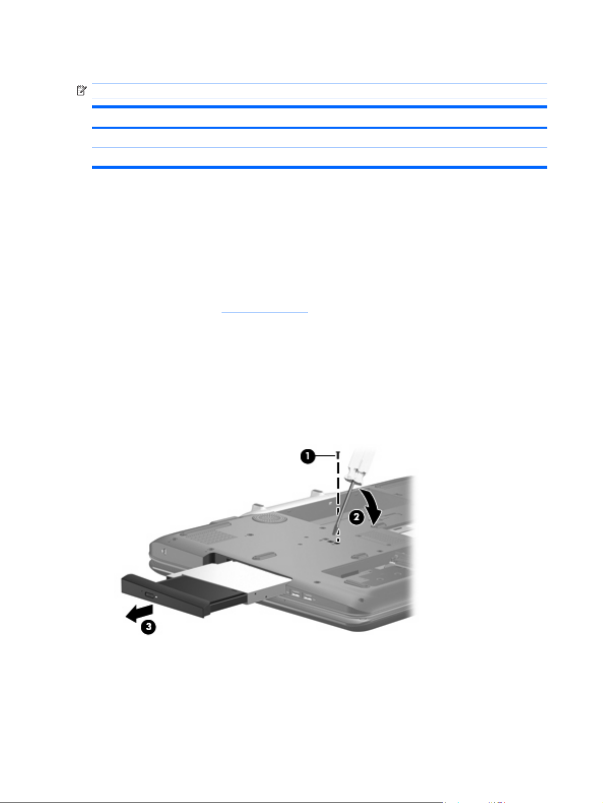
Optical drive
NOTE: All optical drive spare part kits include an optical drive bezel and bracket.
Description Spare part number
HD-DVD 448156-001
DVD±RW and CD-RW Super Multi Double-Layer Combo Drive with LightScribe 448157-001
Before removing the optical drive, follow these steps:
Shut down the computer. If you are unsure whether the computer is off or in Hibernation, turn the
1.
computer on, and then shut it down through the operating system.
Disconnect all external devices connected to the computer.
2.
Disconnect the power from the computer by first unplugging the power cord from the AC outlet and
3.
then unplugging the AC adapter from the computer.
Remove the battery (see
4.
Battery on page 38).
Remove the optical drive:
Position the computer with right side toward you.
1.
2. Remove the Phillips PM2.5×8.0 screw (1) that secures the optical drive to the computer.
3. Insert a flat-bladed screwdriver or similar tool into the optical drive tab access (2) and press the tab
to the left to release the optical drive from the computer.
4. Remove the optical drive (3).
If it is necessary to replace the optical drive bracket, position the optical drive with the optical drive
5.
bracket toward you.
6. Remove the two Phillips PM2.0×3.0 screws (1) that secure the optical drive bracket to the optical
drive.
52 Chapter 4 Removal and replacement procedures
Page 61
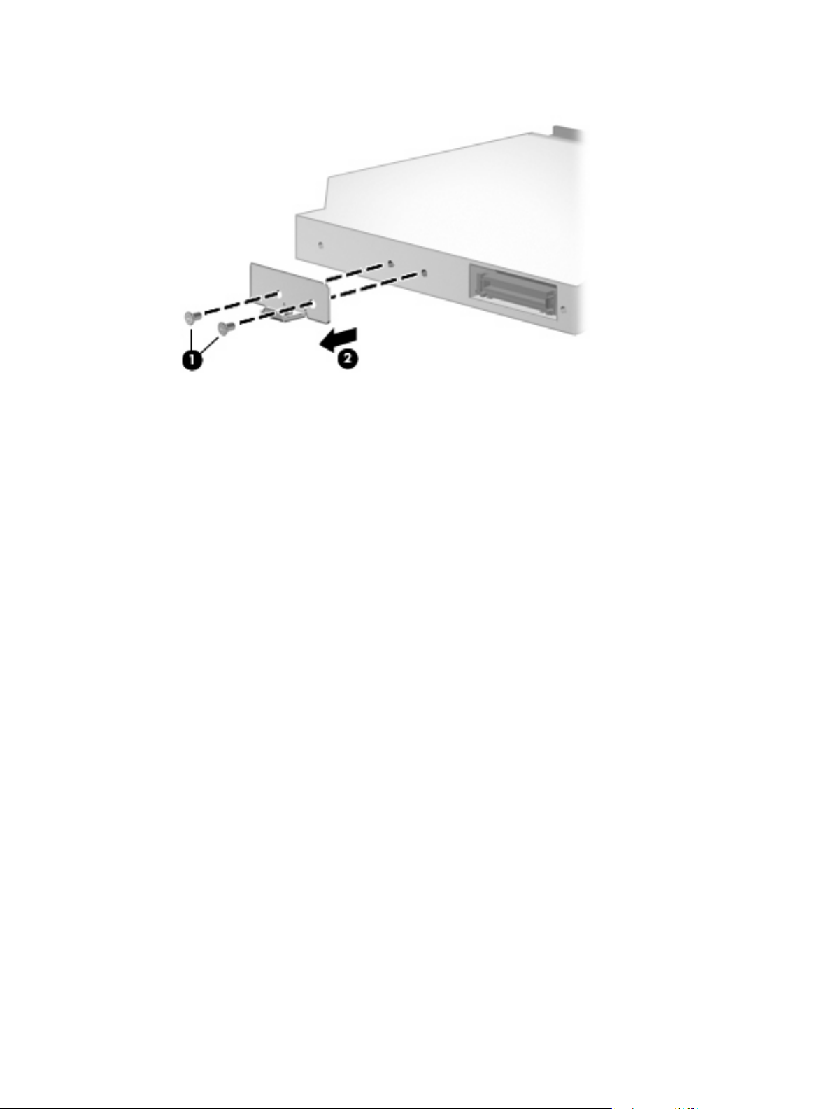
7. Remove the optical drive bracket (2).
Reverse the above procedure to reassemble and install the optical drive.
Component replacement procedures 53
Page 62

Keyboard
Description
For use in: Spare part number For use in: Spare part number
Denmark, Finland, Norway, and
Sweden
France 448159-051 South Korea 448159-AD1
French Canada 448159-121 Spain 448159-071
Germany 448159-041 The United Kingdom 448159-031
The Netherlands and Europe 448159-B31 The United States 448159-001
Italy 448159-061
448159-DH1 Latin America 448159-161
Before removing the keyboard, follow these steps:
Shut down the computer. If you are unsure whether the computer is off or in Hibernation, turn the
1.
computer on, and then shut it down through the operating system.
Disconnect all external devices connected to the computer.
2.
Disconnect the power from the computer by first unplugging the power cord from the AC outlet and
3.
then unplugging the AC adapter from the computer.
Remove the battery (see
4.
Remove the hard drives (see
5.
Battery on page 38).
Hard drive on page 45).
Remove the keyboard:
Position the computer with the front toward you.
1.
2. Remove the three Phillips PM2.5×8.0 screws (1) and the four Phillips PM2.5×5.0 screws (2) that
secure the keyboard to the computer.
Turn the computer display-side up, with the front toward you.
3.
54 Chapter 4 Removal and replacement procedures
Page 63

Open the computer as far as possible.
4.
5. Lift the front edge of the keyboard (1) until it rests at an angle.
6. Slide the keyboard (2) forward until the tabs on the rear edge of the keyboard disengage from the
slots in the top cover.
7. Rotate the rear edge of the keyboard (3) forward until it rests upside down on the palm rest.
8. Release the zero insertion force (ZIF) connector (1) to which the keyboard cable is attached and
disconnect the keyboard cable (2).
Remove the keyboard.
9.
Reverse this procedure to install the keyboard.
Component replacement procedures 55
Page 64
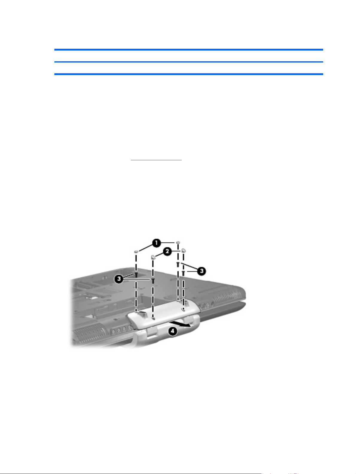
Hinge cover
Description Spare part number
Hinge cover 452311-001
Before removing the hinge cover, follow these steps:
Shut down the computer. If you are unsure whether the computer is off or in Hibernation, turn the
1.
computer on, and then shut it down through the operating system.
Disconnect all external devices connected to the computer.
2.
Disconnect the power from the computer by first unplugging the power cord from the AC outlet and
3.
then unplugging the AC adapter from the computer.
Remove the battery (see
4.
Battery on page 38).
Remove the hinge cover:
Position the computer with the rear panel toward you.
1.
2. Remove the four gray rubber screw covers (1) and (2) from the hinge cover. The screw covers come
in two different sizes and are available in the Rubber Feet Kit, spare part number 452320-001.
3. Remove the four Phillips PM3.0×8.0 screws (3) that secure the hinge cover to the computer.
4. Remove the hinge cover (4) by pulling it away from the computer.
Reverse this procedure to install the hinge cover.
56 Chapter 4 Removal and replacement procedures
Page 65

Rear cover
Description Spare part number
Rear cover 448161-001
Before removing the rear cover, follow these steps:
Shut down the computer. If you are unsure whether the computer is off or in Hibernation, turn the
1.
computer on, and then shut it down through the operating system.
Disconnect all external devices connected to the computer.
2.
Disconnect the power from the computer by first unplugging the power cord from the AC outlet and
3.
then unplugging the AC adapter from the computer.
Remove the battery (see
4.
Remove the hinge cover (see
5.
Battery on page 38).
Hinge cover on page 56).
Remove the rear cover:
Position the computer with the front toward you.
1.
2. Remove the seven Phillips PM2.5×8.0 screws (1) that secure the rear cover to the computer.
3. Remove the Mylar screw cover (2) in the optical drive bay. This screw cover is available in the Rubber
Feet Kit, spare part number 452320-001.
4. Remove the Phillips PM2.5×4.0 screw (3) that secures the rear cover to the computer.
5. Remove the four Phillips PM3.0×12.0 screws (1) that secure the rear cover to the computer.
Component replacement procedures 57
Page 66

6. Remove the four Phillips PM2.5×4.0 broad-head screws (2) that secure the rear cover to the
computer.
Turn the computer right-side up, with the front toward you.
7.
Open the computer as far as possible.
8.
Remove the rear cover.
9.
Reverse this procedure to install the rear cover.
58 Chapter 4 Removal and replacement procedures
Page 67

Top cover
Description Spare part number
Top cover (includes TouchPad board cable and TouchPad button cable, and LED boards and cables) 448174-001
Before removing the top cover, follow these steps:
1.
2.
3.
Shut down the computer. If you are unsure whether the computer is off or in Hibernation, turn the
computer on, and then shut it down through the operating system.
Disconnect all external devices connected to the computer.
Disconnect the power from the computer by first unplugging the power cord from the AC outlet and
then unplugging the AC adapter from the computer.
Remove the battery (see
4.
Remove the following components:
5.
Hard drive (see
a.
Optical drive (see
b.
Keyboard (see
c.
Hinge cover (see
d.
Rear cover (see
e.
Battery on page 38).
Hard drive on page 45)
Optical drive on page 52)
Keyboard on page 54)
Hinge cover on page 56)
Rear cover on page 57)
Remove the top cover:
Turn the computer upside down, with the front toward you.
1.
2. Remove the two Mylar screw covers (1) in the optical drive bay. These screw covers are available
in the Rubber Feet Kit, spare part number 452320-001.
3. Remove the two Phillips PM2.5×4.0 screws (2) and the ten Phillips PM2.5×8.0 screws (3) that secure
the top cover to the computer.
Component replacement procedures 59
Page 68
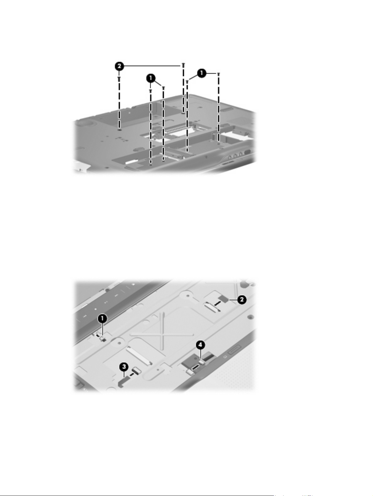
4. Remove the four Phillips PM2.5×5.0 screws (1) and the two Phillips PM2.5×11.0 screws (2) that
secure the top cover to the computer.
Turn the computer right-side up, with the front toward you.
5.
Open the computer as far as possible.
6.
Disconnect the following cables:
7.
(1) Fingerprint reader board cable
(2) LED board cable
(3) TouchPad board cable
(4) TouchPad on/off board cable
8. Remove the two Phillips PM2.5×5.0 screws (1) that secure the top cover to the computer.
60 Chapter 4 Removal and replacement procedures
Page 69

9. Lift the rear edge of the top cover (2) until the top cover disengages from the computer.
Remove the top cover.
10.
Reverse this procedure to install the top cover.
Fingerprint reader board
Description Spare part number
Fingerprint reader board (includes cable) 448166-001
Before removing the fingerprint reader board, follow these steps:
Shut down the computer. If you are unsure whether the computer is off or in Hibernation, turn the
1.
computer on, and then shut it down through the operating system.
Disconnect all external devices connected to the computer.
2.
Disconnect the power from the computer by first unplugging the power cord from the AC outlet and
3.
then unplugging the AC adapter from the computer.
Remove the battery (see
4.
Remove the following components:
5.
Hard drive (see
a.
Optical drive (see
b.
Keyboard (see
c.
Hinge cover (see
d.
Battery on page 38).
Hard drive on page 45)
Optical drive on page 52)
Keyboard on page 54)
Hinge cover on page 56)
Rear cover (see
e.
Top cover (see
f.
Rear cover on page 57)
Top cover on page 59)
Component replacement procedures 61
Page 70

Remove the fingerprint reader board:
Turn the top cover upside down, with the front toward you.
1.
2. Remove the two silver Phillips PM2.0×4.0 screws (1) that secure the fingerprint reader board and
bracket to the top cover.
3. Remove the fingerprint reader board bracket (2) and fingerprint reader board (3).
Reverse this procedure to install the fingerprint reader board.
TouchPad on/off board
Description Spare part number
TouchPad on/off board (includes cable) 448167-001
Before removing the TouchPad on/off board, follow these steps:
Shut down the computer. If you are unsure whether the computer is off or in Hibernation, turn the
1.
computer on, and then shut it down through the operating system.
Disconnect all external devices connected to the computer.
2.
Disconnect the power from the computer by first unplugging the power cord from the AC outlet and
3.
then unplugging the AC adapter from the computer.
Remove the battery (see
4.
Remove the following components:
5.
Hard drive (see
a.
Optical drive (see
b.
Hard drive on page 45)
Battery on page 38).
Optical drive on page 52)
Keyboard (see
c.
Hinge cover (see
d.
Keyboard on page 54)
Hinge cover on page 56)
62 Chapter 4 Removal and replacement procedures
Page 71

Rear cover (see
e.
Rear cover on page 57)
Top cover (see
f.
Top cover on page 59)
Remove the TouchPad on/off board:
Turn the top cover upside down, with the front toward you.
1.
2. Remove the two silver Phillips PM2.0×4.0 screws (1) that secure the TouchPad on/off board to the
top cover.
3. Remove the TouchPad on/off board (2).
Reverse this procedure to install the TouchPad on/off board.
Component replacement procedures 63
Page 72

Display assembly
Description Spare part number
20.1-inch, WSXGA BrightView display assembly (includes camera module and cable, microphones,
speakers, and WLAN antennae)
20.1-inch, WUXGA BrightView display assembly (includes camera module and cable, microphones,
speakers, and WLAN antennae)
452299-001
452300-001
Before removing the display assembly, follow these steps:
Shut down the computer. If you are unsure whether the computer is off or in Hibernation, turn the
1.
computer on, and then shut it down through the operating system.
Disconnect all external devices connected to the computer.
2.
Disconnect the power from the computer by first unplugging the power cord from the AC outlet and
3.
then unplugging the AC adapter from the computer.
Remove the battery (see
4.
Disconnect the WLAN module antenna cables from the WLAN module (see
5.
Battery on page 38).
WLAN module
on page 47).
Remove the following components:
6.
Hard drive (see
a.
Optical drive (see
b.
Hard drive on page 45)
Optical drive on page 52)
Keyboard (see
c.
Hinge cover (see
d.
Rear cover (see
e.
Top cover (see
f.
Keyboard on page 54)
Hinge cover on page 56)
Rear cover on page 57)
Top cover on page 59)
Remove the display assembly:
Close the computer and turn it upside down, with the front toward you.
1.
64 Chapter 4 Removal and replacement procedures
Page 73

Remove the six Phillips PM3.0×8.0 screws that secure the display assembly to the computer.
2.
Turn the computer display-side up, with the front toward you.
3.
Open the computer to an upright position.
4.
Disconnect the following cable connectors:
5.
(1) Display panel cable
(2) Camera module cable
(3) Speaker cable
(4) Microphone cable
NOTE: The speaker cables are black and red and share a single connector. The microphone cables
are gray and white and share a single connector. Be sure that these connectors are correctly
reconnected when installing the display assembly.
Component replacement procedures 65
Page 74

6. Remove the WLAN antenna cables (5) from the opening in the system board.
CAUTION: The display assembly will be unsupported when the following screws are removed. To
prevent damage to the display assembly, support the display assembly before removing the screws.
7. Remove the six Phillips PM3.0×8.0 screws (1) that secure the display assembly to the computer.
8. Remove the display assembly (2).
NOTE: If it is necessary to replace any of the display assembly internal components, see Display
assembly internal components on page 40 for display bezel removal information.
Reverse this procedure to install the display assembly.
66 Chapter 4 Removal and replacement procedures
Page 75

Audio/infrared board
Description Spare part number
Audio/infrared board 452316-001
Before removing the audio/infrared board, follow these steps:
Shut down the computer. If you are unsure whether the computer is off or in Hibernation, turn the
1.
computer on, and then shut it down through the operating system.
Disconnect all external devices connected to the computer.
2.
Disconnect the power from the computer by first unplugging the power cord from the AC outlet and
3.
then unplugging the AC adapter from the computer.
Remove the battery (see
4.
Remove the following components:
5.
Hard drive (see
a.
Optical drive (see
b.
Keyboard (see
c.
Hinge cover (see
d.
Rear cover (see
e.
Top cover (see
f.
Battery on page 38).
Hard drive on page 45)
Optical drive on page 52)
Keyboard on page 54)
Hinge cover on page 56)
Rear cover on page 57)
Top cover on page 59)
Remove the audio/infrared board:
1. Disconnect the audio/infrared board cable (1) from the system board.
2. Remove the two Phillips PM2.5×5.0 screws (2) that secure the audio/infrared board to the computer.
3. Remove the audio/infrared board (3) from the base enclosure.
Component replacement procedures 67
Page 76

Reverse this procedure to install the audio/infrared board.
Bluetooth module
NOTE: The Bluetooth module spare part kit does not include a Bluetooth module cable. The Bluetooth
module cable is available in the Cable Kit, spare part number 448169-001.
Description Spare part number
Bluetooth module 398393-002
Before removing the Bluetooth module, follow these steps:
Shut down the computer. If you are unsure whether the computer is off or in Hibernation, turn the
1.
computer on, and then shut it down through the operating system.
Disconnect all external devices connected to the computer.
2.
Disconnect the power from the computer by first unplugging the power cord from the AC outlet and
3.
then unplugging the AC adapter from the computer.
Remove the battery (see
4.
Remove the following components:
5.
Hard drive (see
a.
Optical drive (see
b.
Keyboard (see
c.
Hinge cover (see
d.
Rear cover (see
e.
Top cover (see
f.
Battery on page 38).
Hard drive on page 45)
Optical drive on page 52)
Keyboard on page 54)
Hinge cover on page 56)
Rear cover on page 57)
Top cover on page 59)
Remove the Bluetooth module:
1. Disconnect the Bluetooth module cable (1) from the system board.
2. Remove the two silver Phillips PM2.0×4.0 screws (2) that secure the Bluetooth module to the
computer.
68 Chapter 4 Removal and replacement procedures
Page 77

3. Remove the Bluetooth module (3) from the base enclosure.
Reverse this procedure to install the Bluetooth module.
Front USB board
Description Spare part number
Front USB board 452314-001
Before removing the front USB board, follow these steps:
Shut down the computer. If you are unsure whether the computer is off or in Hibernation, turn the
1.
computer on, and then shut it down through the operating system.
Disconnect all external devices connected to the computer.
2.
Disconnect the power from the computer by first unplugging the power cord from the AC outlet and
3.
then unplugging the AC adapter from the computer.
Remove the battery (see
4.
Remove the following components:
5.
Hard drive (see
a.
Optical drive (see
b.
Keyboard (see
c.
Hinge cover (see
d.
Rear cover (see
e.
Battery on page 38).
Hard drive on page 45)
Optical drive on page 52)
Keyboard on page 54)
Hinge cover on page 56)
Rear cover on page 57)
Top cover (see
f.
Top cover on page 59)
Component replacement procedures 69
Page 78

Remove the front USB board:
1. Disconnect the front USB board cable (1) from the system board.
2. Remove the two Phillips PM2.5×4.0 screws (2) that secure front USB board the to the computer.
3. Remove the front USB board (3).
Reverse this procedure to install the front USB board.
Power connector LED board
Description Spare part number
Power connector LED board (includes cable) 452318-001
Before removing the power connector LED board, follow these steps:
Shut down the computer. If you are unsure whether the computer is off or in Hibernation, turn the
1.
computer on, and then shut it down through the operating system.
Disconnect all external devices connected to the computer.
2.
Disconnect the power from the computer by first unplugging the power cord from the AC outlet and
3.
then unplugging the AC adapter from the computer.
Remove the battery (see
4.
Remove the following components:
5.
Hard drive (see
a.
Optical drive (see
b.
Keyboard (see
c.
Battery on page 38).
Hard drive on page 45)
Optical drive on page 52)
Keyboard on page 54)
Hinge cover (see
d.
Hinge cover on page 56)
70 Chapter 4 Removal and replacement procedures
Page 79

Rear cover (see
e.
Rear cover on page 57)
Top cover (see
f.
Top cover on page 59)
Remove the power connector LED board:
1. Disconnect the power connector LED board (1) from the system board.
2. Remove the power connector LED board (2).
Reverse this procedure to install the power connector LED board.
Rear USB board
Description Spare part number
Rear USB board (includes cable) 452315-001
Before removing the rear USB board, follow these steps:
Shut down the computer. If you are unsure whether the computer is off or in Hibernation, turn the
1.
computer on, and then shut it down through the operating system.
Disconnect all external devices connected to the computer.
2.
Disconnect the power from the computer by first unplugging the power cord from the AC outlet and
3.
then unplugging the AC adapter from the computer.
Remove the battery (see
4.
Remove the following components:
5.
Hard drive (see
a.
Optical drive (see
b.
Keyboard (see
c.
Battery on page 38).
Hard drive on page 45)
Optical drive on page 52)
Keyboard on page 54)
Hinge cover (see
d.
Hinge cover on page 56)
Component replacement procedures 71
Page 80

Rear cover (see
e.
Rear cover on page 57)
Top cover (see
f.
Top cover on page 59)
Remove the rear USB board:
1. Disconnect the rear USB board cable (1) from the system board.
2. Remove the Phillips PM2.5×4.0 screw (2) that secures rear USB board the to the computer.
3. Remove the rear USB board (3).
Reverse this procedure to install the rear USB board.
Subwoofer
Description Spare part number
Subwoofer (includes rubber isolators) 448164-001
Before removing the subwoofer, follow these steps:
Shut down the computer. If you are unsure whether the computer is off or in Hibernation, turn the
1.
computer on, and then shut it down through the operating system.
Disconnect all external devices connected to the computer.
2.
Disconnect the power from the computer by first unplugging the power cord from the AC outlet and
3.
then unplugging the AC adapter from the computer.
Remove the battery (see
4.
Remove the following components:
5.
a.
b.
Hard drive (see
Hard drive on page 45)
Optical drive (see
Battery on page 38).
Optical drive on page 52)
Keyboard (see
c.
Keyboard on page 54)
72 Chapter 4 Removal and replacement procedures
Page 81

Hinge cover (see
d.
Hinge cover on page 56)
Rear cover (see
e.
Top cover (see
f.
Rear cover on page 57)
Top cover on page 59)
Remove the subwoofer:
1. Disconnect the subwoofer cable (1) from the system board.
2. Remove the three Phillips PM2.5×8.0 screws (2) that secure subwoofer the to the base enclosure.
3. Remove the subwoofer (3).
CAUTION: When installing the subwoofer, do not overtighten the screws. Overtightening the
subwoofer screws can result in damage to the subwoofer grommets (4), which can cause a decrease
in the subwoofer performance.
Reverse this procedure to install the subwoofer.
Video connector board
Description Spare part number
Video connector board (includes cable) 452321-001
Before removing the audio connector board, follow these steps:
Shut down the computer. If you are unsure whether the computer is off or in Hibernation, turn the
1.
computer on, and then shut it down through the operating system.
Disconnect all external devices connected to the computer.
2.
Disconnect the power from the computer by first unplugging the power cord from the AC outlet and
3.
then unplugging the AC adapter from the computer.
Component replacement procedures 73
Page 82

Remove the battery (see
4.
Remove the following components:
5.
Battery on page 38).
Hard drive (see
a.
Optical drive (see
b.
Keyboard (see
c.
Hinge cover (see
d.
Rear cover (see
e.
Top cover (see
f.
Subwoofer (see
g.
Hard drive on page 45)
Optical drive on page 52)
Keyboard on page 54)
Hinge cover on page 56)
Rear cover on page 57)
Top cover on page 59)
Subwoofer on page 72)
Remove the video connector board:
1. Disconnect the video connector board cable (1) from the system board.
2. Remove the Phillips PM2.5×4.0 screw (2) that secures the video connector board to the base
enclosure.
3. Route the video connector board cable under the processor heat sink pipe (3).
4. Remove the video connector board (4) from the base enclosure.
Reverse this procedure to install the video connector board.
74 Chapter 4 Removal and replacement procedures
Page 83

Processor fan
Description Spare part number
Processor fan 448162-001
NOTE: To properly ventilate the computer, allow at least a 7.6-cm (3-inch) clearance on the left and
right sides and rear panel of the computer. The computer uses two electric fans for ventilation. The fans
are controlled by a temperature sensor and are designed to turn on automatically when high temperature
conditions exist. These conditions are affected by high external temperatures, system power consumption,
power management/battery conservation configurations, battery fast charging, and software
requirements. Exhaust air is displaced through the ventilation grills located on the computer rear panel.
Before removing the processor fan, follow these steps:
Shut down the computer. If you are unsure whether the computer is off or in Hibernation, turn the
1.
computer on, and then shut it down through the operating system.
Disconnect all external devices connected to the computer.
2.
Disconnect the power from the computer by first unplugging the power cord from the AC outlet and
3.
then unplugging the AC adapter from the computer.
Remove the battery (see
4.
Remove the following components:
5.
Hard drive (see
a.
Optical drive (see
b.
Keyboard (see
c.
Hinge cover (see
d.
Rear cover (see
e.
Top cover (see
f.
Subwoofer (see
g.
Battery on page 38).
Hard drive on page 45)
Optical drive on page 52)
Keyboard on page 54)
Hinge cover on page 56)
Rear cover on page 57)
Top cover on page 59)
Subwoofer on page 72)
Remove the processor fan:
1. Disconnect the processor fan cable (1) from the system board.
2. Remove the two Phillips PM2.5×8.0 screws (2) that secure the processor fan to the base enclosure.
Component replacement procedures 75
Page 84

3. Remove the processor fan (3).
Reverse this procedure to install the processor fan.
System board
Description Spare part number
System board (includes power connector cable, ExpressCard assembly, and replacement thermal
material)
448145-001
Before removing the system board, follow these steps:
Shut down the computer. If you are unsure whether the computer is off or in Hibernation, turn the
1.
computer on, and then shut it down through the operating system.
Disconnect all external devices connected to the computer.
2.
Disconnect the power from the computer by first unplugging the power cord from the AC outlet and
3.
then unplugging the AC adapter from the computer.
Remove the battery (see
4.
Remove the following components:
5.
Hard drive (see
a.
Optical drive (see
b.
Keyboard (see
c.
Hinge cover (see
d.
Rear cover (see
e.
Battery on page 38).
Hard drive on page 45)
Optical drive on page 52)
Keyboard on page 54)
Hinge cover on page 56)
Rear cover on page 57)
Top cover (see
f.
Subwoofer (see
g.
Processor fan (see
h.
Top cover on page 59)
Subwoofer on page 72)
Processor fan on page 75)
76 Chapter 4 Removal and replacement procedures
Page 85
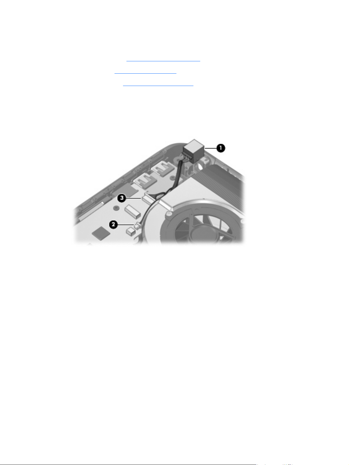
When replacing the system board, be sure that the following components are removed from the defective
system board and installed on the replacement system board:
Memory module (see
●
RTC battery (see
●
WLAN module (see
●
Memory module on page 50)
RTC battery on page 81)
WLAN module on page 47)
Remove the system board:
1. Remove the power connector (1) from the clip built into the base enclosure.
2. Disconnect the rear USB board cable (2) and the power connector LED board cable (3) from the
system board.
Component replacement procedures 77
Page 86

Disconnect the following cable connectors from the system board:
3.
(1) Speaker cable
(2) Microphone cable
(3) Audio/infrared board cable
(4) Subwoofer cable
(5) Audio connector board cable
Disconnect the following cables from the system board:
4.
(1) Bluetooth module cable
(2) Front USB board cable
(3) Processor fan cable
(4) Composite video connector board cable
5. Remove the two SM1.5×9.0 screws (1) on each side of the expansion port 3 connector.
78 Chapter 4 Removal and replacement procedures
Page 87

6. Remove the four Phillips PM2.5×4.0 screws (2) that secure the system board to the base enclosure.
7. Loosen the captive Phillips PM2.5×14.0 screw (3) that secures the video heat sink and system board
to the base enclosure.
8. Use the optical drive connector (1) to lift the right side of the system board (2) until it rests at an
angle.
9. Remove the system board (3) by pulling it away from the base enclosure at an angle.
Reverse this procedure to install the system board.
Component replacement procedures 79
Page 88

Audio connector board
Description Spare part number
Audio connector board (includes cable) 452317-001
Before removing the audio connector board, follow these steps:
Shut down the computer. If you are unsure whether the computer is off or in Hibernation, turn the
1.
computer on, and then shut it down through the operating system.
Disconnect all external devices connected to the computer.
2.
Disconnect the power from the computer by first unplugging the power cord from the AC outlet and
3.
then unplugging the AC adapter from the computer.
Remove the battery (see
4.
Remove the following components:
5.
Hard drive (see
a.
Optical drive (see
b.
Keyboard (see
c.
Hinge cover (see
d.
Rear cover (see
e.
Top cover (see
f.
Subwoofer (see
g.
System board (see
h.
Battery on page 38).
Hard drive on page 45)
Optical drive on page 52)
Keyboard on page 54)
Hinge cover on page 56)
Rear cover on page 57)
Top cover on page 59)
Subwoofer on page 72)
System board on page 76)
Remove the audio connector board:
1. Remove the two Phillips PM2.5×5.0 screws (1) that secure the audio connector board to the base
enclosure.
2. Remove the audio connector board cable (2) from the clips built into the base enclosure.
80 Chapter 4 Removal and replacement procedures
Page 89

3. Remove the audio connector board (3) from the base enclosure.
Reverse this procedure to install the audio connector board.
RTC battery
NOTE: Removing the RTC battery and leaving it uninstalled for 5 or more minutes causes all passwords
and CMOS settings to be cleared.
Description Spare part number
RTC battery 452319-001
Before removing the RTC battery, follow these steps:
Shut down the computer. If you are unsure whether the computer is off or in Hibernation, turn the
1.
computer on, and then shut it down through the operating system.
Disconnect all external devices connected to the computer.
2.
Disconnect the power from the computer by first unplugging the power cord from the AC outlet and
3.
then unplugging the AC adapter from the computer.
Remove the battery (see
4.
Remove the following components:
5.
Hard drive (see
a.
Optical drive (see
b.
Keyboard (see
c.
Hinge cover (see
d.
Battery on page 38).
Hard drive on page 45)
Optical drive on page 52)
Keyboard on page 54)
Hinge cover on page 56)
Rear cover (see
e.
Top cover (see
f.
Rear cover on page 57)
Top cover on page 59)
Component replacement procedures 81
Page 90

Subwoofer (see
g.
Subwoofer on page 72)
System board (see
h.
System board on page 76)
Remove the RTC battery:
Remove the RTC battery from the socket on the system board.
▲
Reverse this procedure to install the RTC battery.
82 Chapter 4 Removal and replacement procedures
Page 91

Processor heat sink
Description Spare part number
Processor heat sink (includes replacement thermal material) 448175-001
Before removing the processor heat sink, follow these steps:
Shut down the computer. If you are unsure whether the computer is off or in Hibernation, turn the
1.
computer on, and then shut it down through the operating system.
Disconnect all external devices connected to the computer.
2.
Disconnect the power from the computer by first unplugging the power cord from the AC outlet and
3.
then unplugging the AC adapter from the computer.
Remove the battery (see
4.
Remove the following components:
5.
Hard drive (see
a.
Optical drive (see
b.
Keyboard (see
c.
Hinge cover (see
d.
Rear cover (see
e.
Top cover (see
f.
Subwoofer (see
g.
System board (see
h.
Battery on page 38).
Hard drive on page 45)
Optical drive on page 52)
Keyboard on page 54)
Hinge cover on page 56)
Rear cover on page 57)
Top cover on page 59)
Subwoofer on page 72)
System board on page 76)
Remove the processor heat sink:
Turn the system board upside down, with the front toward you.
1.
2. Loosen the three silver Phillips PM2.0×5.0 captive screws (1) that secure the processor heat sink to
the system board.
3. Remove the processor heat sink clip (2) by sliding it to the right.
Component replacement procedures 83
Page 92
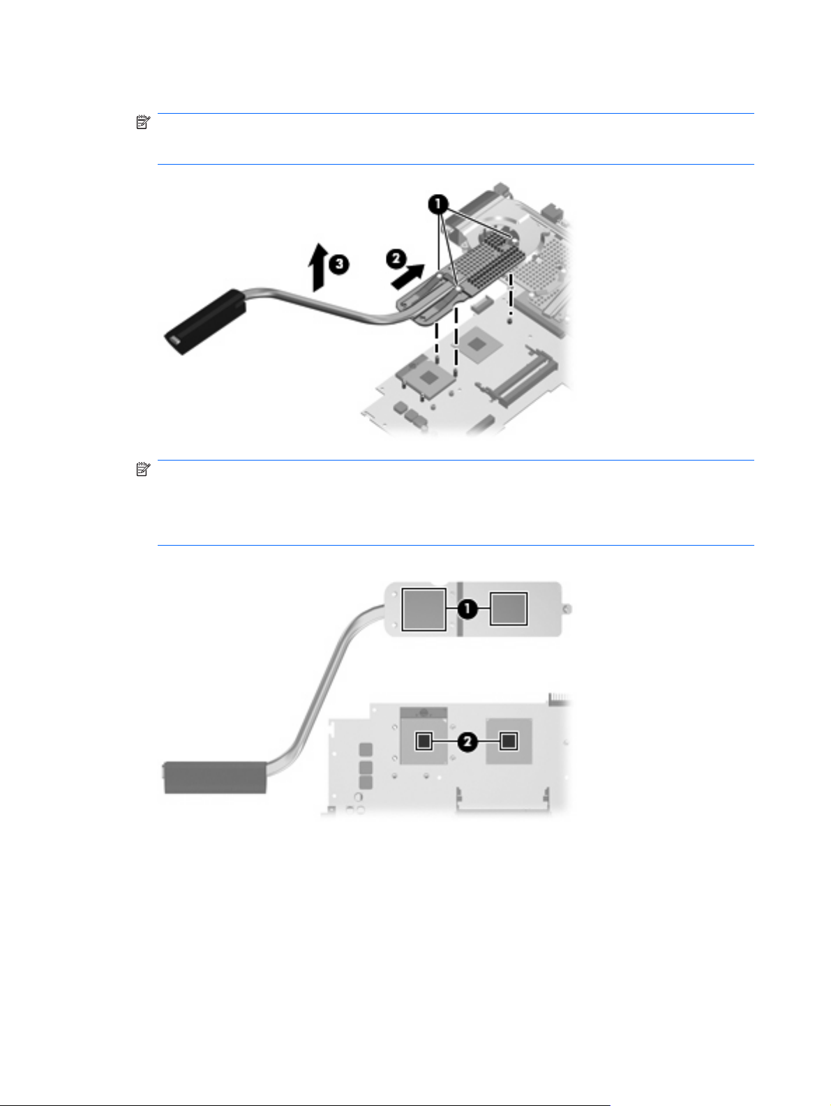
4. Remove the processor heat sink (3).
NOTE: Due to the adhesive quality of the thermal material located between the processor heat sink
and system board components, it may be necessary to move the processor heat sink from side to
side to detach it.
NOTE: The thermal material must be thoroughly cleaned from the surfaces of the processor heat
sink (1) and the system board (2) each time the processor heat sink is removed. Thermal material
must be installed on all surfaces before the processor heat sink is reinstalled. Replacement thermal
material is included with all processor heat sink, system board, and processor spare part kits, and
is also available using spare part number 413706-001.
Reverse this procedure to install the processor heat sink.
84 Chapter 4 Removal and replacement procedures
Page 93

Processor
NOTE: All processor spare part kits include replacement thermal material.
Desription Spare part number
Intel Core 2 Extreme processors (4-MB L2 cache, 800-MHz FSB, 44-W):
X7900 2.8-GHz processor
X7800 2.6-GHz processor 455738-001 and
Intel Core 2 Duo processors (4-MB L2 cache, 800-MHz FSB, 35-W):
T7700 2.4-GHz processor
T7500 2.2-GHz processor 448147-001
T7300 2.0-GHz processor 448146-001
T7100 1.8-GHz processor 448149-001
453908-001
452327-001
448148-001
Before removing the processor, follow these steps:
Shut down the computer. If you are unsure whether the computer is off or in Hibernation, turn the
1.
computer on, and then shut it down through the operating system.
Disconnect all external devices connected to the computer.
2.
Disconnect the power from the computer by first unplugging the power cord from the AC outlet and
3.
then unplugging the AC adapter from the computer.
Remove the battery (see
4.
Battery on page 38).
Remove the following components:
5.
Hard drive (see
a.
Optical drive (see
b.
Keyboard (see
c.
Hinge cover (see
d.
Rear cover (see
e.
Top cover (see
f.
Subwoofer (see
g.
System board (see
h.
Processor heat sink (see
i.
Hard drive on page 45)
Optical drive on page 52)
Keyboard on page 54)
Hinge cover on page 56)
Rear cover on page 57)
Top cover on page 59)
Subwoofer on page 72)
System board on page 76)
Processor heat sink on page 83)
Remove the processor:
1. Turn the processor locking screw (1) one-half turn counterclockwise until you hear a click.
Component replacement procedures 85
Page 94

2. Lift the processor (2) straight up and remove it.
NOTE: The gold triangle (3) on the processor must be aligned with the triangle icon (4) embossed
on the processor slot when you install the processor.
Reverse this procedure to install the processor.
86 Chapter 4 Removal and replacement procedures
Page 95

Video board heat sink
Description Spare part number
Video board heat sink (includes replacement thermal material) 448176-001
Before removing the video board heat sink, follow these steps:
Shut down the computer. If you are unsure whether the computer is off or in Hibernation, turn the
1.
computer on, and then shut it down through the operating system.
Disconnect all external devices connected to the computer.
2.
Disconnect the power from the computer by first unplugging the power cord from the AC outlet and
3.
then unplugging the AC adapter from the computer.
Remove the battery (see
4.
Remove the following components:
5.
Hard drive (see
a.
Optical drive (see
b.
Keyboard (see
c.
Hinge cover (see
d.
Rear cover (see
e.
Top cover (see
f.
Subwoofer (see
g.
System board (see
h.
Battery on page 38).
Hard drive on page 45)
Optical drive on page 52)
Keyboard on page 54)
Hinge cover on page 56)
Rear cover on page 57)
Top cover on page 59)
Subwoofer on page 72)
System board on page 76)
Remove the video board heat sink:
Turn the system board upside down, with the front toward you.
1.
2. Disconnect the video board fan cable (1) from the system board.
3. Loosen the two Phillips PM2.5×9.0 captive screws (2) and the four silver Phillips PM2.0×5.0 captive
screws (3) that secure the video board heat sink to the system board.
Component replacement procedures 87
Page 96
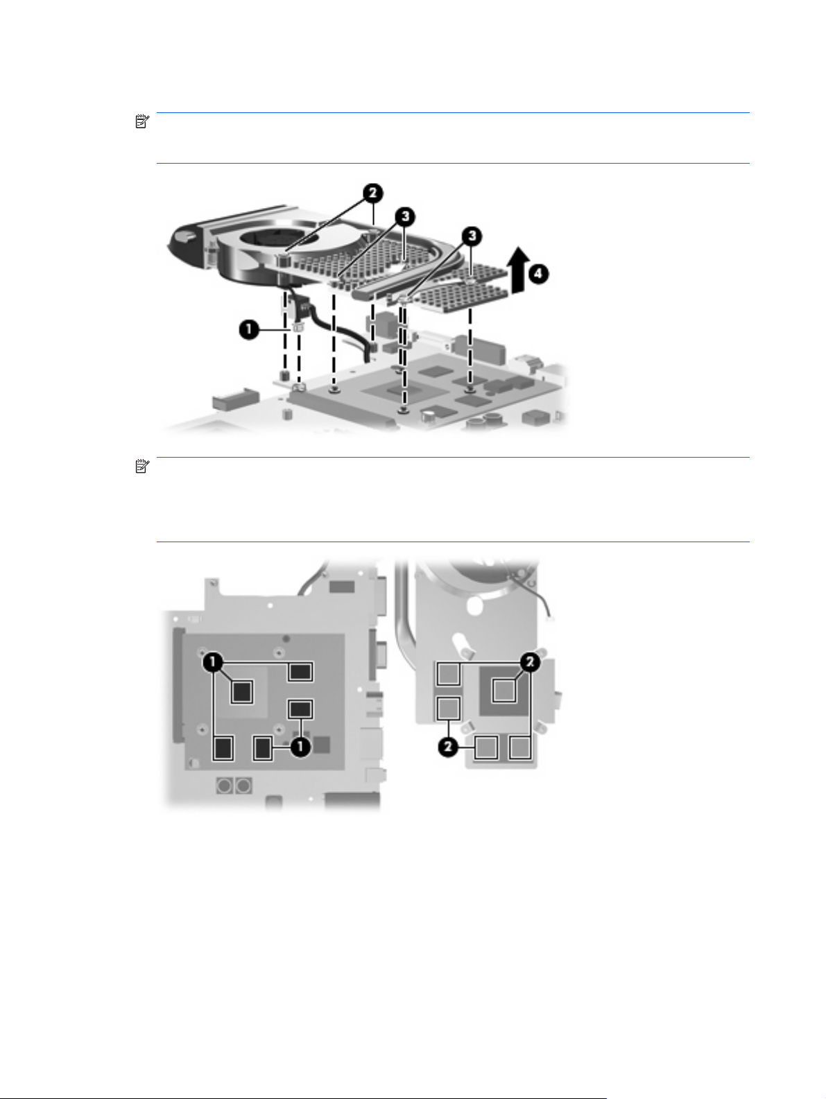
4. Remove the video board heat sink (4).
NOTE: Due to the adhesive quality of the thermal material located between the video board heat
sink and system board components, it may be necessary to move the video board heat sink from
side to side to detach it.
NOTE: The thermal material must be thoroughly cleaned from the surfaces of the video board
components (1) and the video board heat sink (2) each time the video board heat sink is removed.
Thermal material must be installed on all surfaces before the video board heat sink is reinstalled.
Replacement thermal material is included with all video board heat sink and video board spare part
kits, and is also available using spare part number 413706-001.
Reverse this procedure to install the video board heat sink.
88 Chapter 4 Removal and replacement procedures
Page 97

Video board fan
Description Spare part number
Video board fan 448163-001
NOTE: To properly ventilate the computer, allow at least a 7.6-cm (3-inch) clearance on the left and
right sides and rear panel of the computer. The computer uses two electric fans for ventilation. The fans
are controlled by a temperature sensor and are designed to turn on automatically when high temperature
conditions exist. These conditions are affected by high external temperatures, system power consumption,
power management/battery conservation configurations, battery fast charging, and software
requirements. Exhaust air is displaced through the ventilation grills located on the computer rear panel.
Before removing the video board fan, follow these steps:
Shut down the computer. If you are unsure whether the computer is off or in Hibernation, turn the
1.
computer on, and then shut it down through the operating system.
Disconnect all external devices connected to the computer.
2.
Disconnect the power from the computer by first unplugging the power cord from the AC outlet and
3.
then unplugging the AC adapter from the computer.
Remove the battery (see
4.
Remove the following components:
5.
Hard drive (see
a.
Optical drive (see
b.
Keyboard (see
c.
Hinge cover (see
d.
Rear cover (see
e.
Top cover (see
f.
Subwoofer (see
g.
System board (see
h.
Video board heat sink (see
i.
Battery on page 38).
Hard drive on page 45)
Optical drive on page 52)
Keyboard on page 54)
Hinge cover on page 56)
Rear cover on page 57)
Top cover on page 59)
Subwoofer on page 72)
System board on page 76)
Video board heat sink on page 87)
Remove the video board fan:
Turn the video heat sink upside down.
1.
2. Remove the three black Phillips PM2.0×4.0 screws (1) that secure the video board fan to the video
board heat sink.
Component replacement procedures 89
Page 98
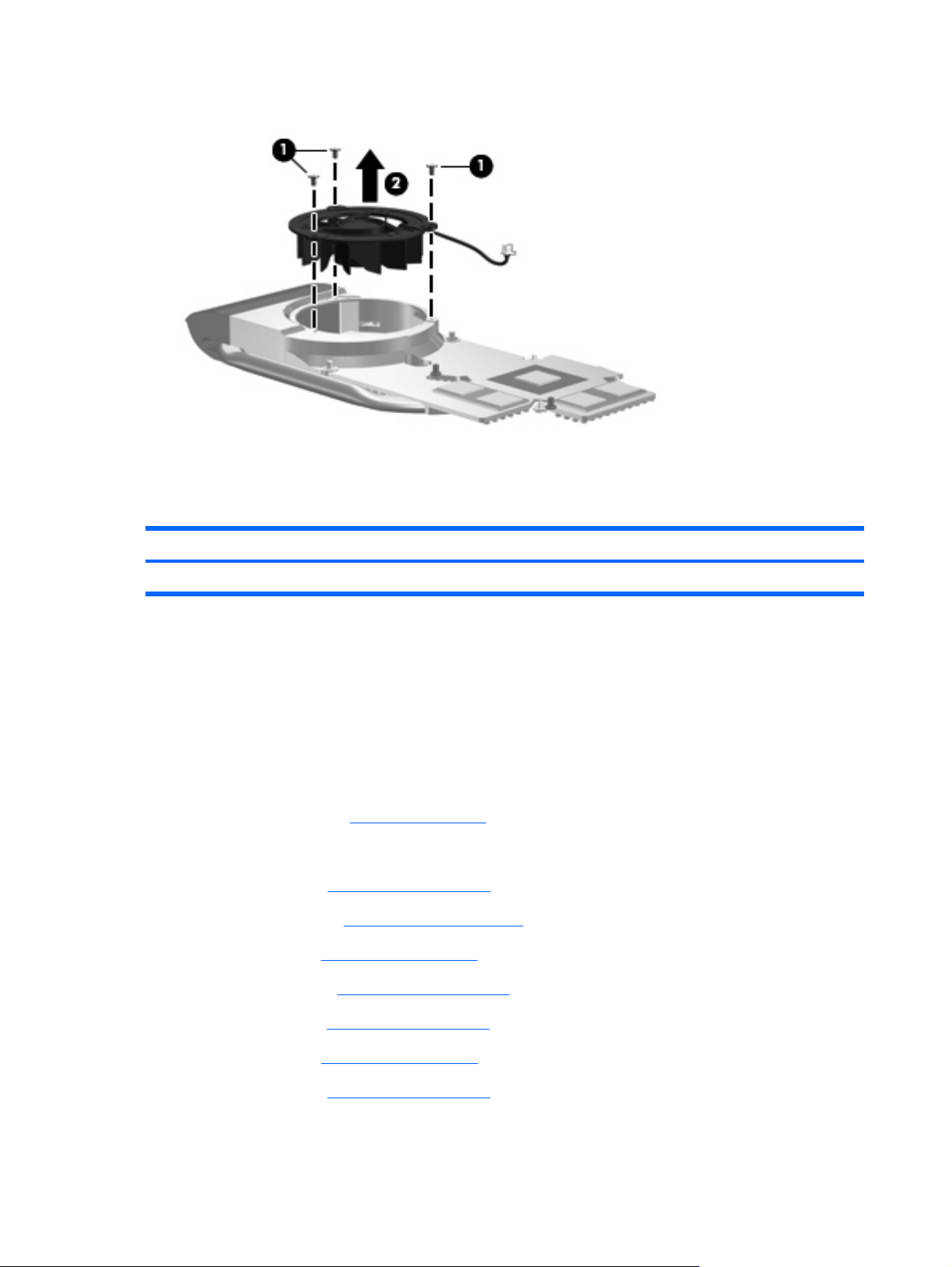
3. Remove the video board fan (2).
Reverse this procedure to install the video board fan.
Video board
Description Spare part number
nVidia video board (includes replacement thermal material) 454311-001
Before removing the video board fan, follow these steps:
Shut down the computer. If you are unsure whether the computer is off or in Hibernation, turn the
1.
computer on, and then shut it down through the operating system.
Disconnect all external devices connected to the computer.
2.
Disconnect the power from the computer by first unplugging the power cord from the AC outlet and
3.
then unplugging the AC adapter from the computer.
Remove the battery (see
4.
Remove the following components:
5.
Hard drive (see
a.
Optical drive (see
b.
Keyboard (see
c.
Hinge cover (see
d.
Rear cover (see
e.
Battery on page 38).
Hard drive on page 45)
Optical drive on page 52)
Keyboard on page 54)
Hinge cover on page 56)
Rear cover on page 57)
Top cover (see
f.
Subwoofer (see
g.
Top cover on page 59)
Subwoofer on page 72)
90 Chapter 4 Removal and replacement procedures
Page 99

System board (see
h.
System board on page 76)
Video board heat sink (see
i.
Video board heat sink on page 87)
Remove the video board:
1. Remove the two Phillips PM2.5×4.0 screws (1) that secure the video board to the system board.
2. Lift the right side of the video board (2) until it rests at an angle.
3. Remove the video board (3) by pulling it away from the video board slot at an angle.
NOTE: Video boards are designed with a notch (4) to prevent incorrect installation into the video
board slot.
Reverse this procedure to install the video board.
Component replacement procedures 91
Page 100

5
Computer Setup
Starting Computer Setup
Computer Setup is a ROM-based information and customization utility that can be used even when the
Windows operating system is not working or will not load.
NOTE: The fingerprint reader does not work when accessing Computer Setup.
The utility reports information about the computer and provides settings for startup, security, and other
preferences.
To start Computer Setup:
Turn on or restart the computer.
1.
Before Windows opens and while "F10 = ROM Based Setup" is displayed in the lower-left corner
2.
of the screen, press f10.
92 Chapter 5 Computer Setup
 Loading...