

Page 1

HP Pavilion dv5 Entertainment PC
Maintenance and Service Guide
Page 2

© Copyright 2010 Hewlett-Packard
Development Company, L.P.
AMD, the AMD Arrow logo, Athlon,
Phenom, Sempron, Turion, and
combinations thereof, are trademarks of
Advanced Micro Devices, Inc. Bluetooth is a
trademark owned by its proprietor and used
by Hewlett-Packard Company under license.
Intel, Core, and Pentium are U.S. registered
trademarks of Intel Corporation. Java is a
U.S. trademark of Sun Microsystems, Inc.
Microsoft, Windows, and Windows Vista
are U.S. registered trademarks of Microsoft
Corporation. SD Logo is a trademark of its
proprietor.
The information contained herein is subject
to change without notice. The only
warranties for HP products and services are
set forth in the express warranty statements
accompanying such products and services.
Nothing herein should be construed as
constituting an additional warranty. HP shall
not be liable for technical or editorial errors
or omissions contained herein.
Third Edition: December 2010
Second Edition: August 2010
First Edition: May 2010
Document Part Number: 600303-001
Revision B
Page 3

Revision history
Revision Publication date Description
A August 2010
B December 2010
●
Chapter 1 — added new
descriptions for processors
●
Chapter 3 and Chapter 4 —
added new spare part numbers
and descriptions for the following
components:
◦
Display assembly in
watergarden finish
◦
Display enclosure in
watergarden finish
◦
Keyboard in watergarden
finish
◦
Processor
◦
Top cover in watergarden
finish
●
Chapter 1 — added new
descriptions for hard drives and
processors
●
Chapter 3 and Chapter 4 —
added new spare part numbers
and descriptions for the following
components:
◦
Display bezel in watergarden
finish
◦
Hard drives without connector
cable and isolator
◦
Keyboard in watergarden
finish for use in Brazil and
Latin America
◦
Processor
iii
Page 4

iv Revision history
Page 5

Safety warning notice
WARNING! To reduce the possibility of heat-related injuries or of overheating the computer, do not
place the computer directly on your lap or obstruct the computer air vents. Use the computer only on a
hard, flat surface. Do not allow another hard surface, such as an adjoining optional printer, or a soft
surface, such as pillows or rugs or clothing, to block airflow. Also, do not allow the AC adapter to
contact the skin or a soft surface, such as pillows or rugs or clothing, during operation. The computer
and the AC adapter comply with the user-accessible surface temperature limits defined by the
International Standard for Safety of Information Technology Equipment (IEC 60950).
v
Page 6

vi Safety warning notice
Page 7

Table of contents
1 Product description ........................................................................................................... 1
2 External component identification ..................................................................................... 9
Identifying the hardware ........................................................................................................... 9
Top components ..................................................................................................................... 10
Display components ................................................................................................ 10
Wireless antenna locations ....................................................................................... 11
Buttons ................................................................................................................... 12
Keys ...................................................................................................................... 13
Lights ..................................................................................................................... 14
TouchPad ............................................................................................................... 15
Front components ................................................................................................................... 16
Left-side components ............................................................................................................... 17
Right-side components ............................................................................................................ 18
Bottom components ................................................................................................................ 19
3 Illustrated parts catalog .................................................................................................. 20
Service tag ............................................................................................................................ 21
Computer major components ................................................................................................... 22
Display assembly subcomponents ............................................................................................. 31
Cable Kit .............................................................................................................................. 33
Plastics Kit ............................................................................................................................. 33
Mass storage devices ............................................................................................................. 34
Miscellaneous parts ................................................................................................................ 35
Sequential part number listing .................................................................................................. 35
4 Removal and replacement procedures ............................................................................ 43
Preliminary replacement requirements ....................................................................................... 43
Tools required ......................................................................................................... 43
Service considerations ............................................................................................. 43
Plastic parts ............................................................................................. 43
vii
Page 8

Cables and connectors ............................................................................. 43
Drive handling ......................................................................................... 44
Grounding guidelines .............................................................................................. 44
Electrostatic discharge damage .................................................................. 44
Packaging and transporting guidelines ........................................ 46
Component replacement procedures ........................................................................................ 48
Service tag ............................................................................................................. 48
Computer feet ......................................................................................................... 49
Battery ................................................................................................................... 49
Memory module ...................................................................................................... 50
WLAN module ........................................................................................................ 53
WWAN module ..................................................................................................... 56
Hard drive ............................................................................................................. 58
RTC battery ............................................................................................................ 62
Optical drive .......................................................................................................... 63
Keyboard ............................................................................................................... 64
Top cover ............................................................................................................... 67
Power button board ................................................................................................. 70
Bluetooth module .................................................................................................... 71
Speakers ................................................................................................................ 72
Optical drive cable ................................................................................................. 73
USB board ............................................................................................................. 74
Power connector cable ............................................................................................ 75
System board ......................................................................................................... 76
Fan/heat sink assembly ........................................................................................... 80
Processor ............................................................................................................... 83
Display assembly .................................................................................................... 86
5 Setup Utility .................................................................................................................... 94
Starting Setup Utility ............................................................................................................... 94
Using Setup Utility .................................................................................................................. 94
Changing the language of Setup Utility ...................................................................... 94
Navigating and selecting in Setup Utility .................................................................... 95
Display system information ....................................................................................... 95
Restoring default settings in Setup Utility ..................................................................... 96
Exiting Setup Utility ................................................................................................. 96
Setup Utility menus ................................................................................................................. 97
Main menu ............................................................................................................. 97
Security menu ......................................................................................................... 97
System Configuration menu ...................................................................................... 97
Diagnostics menu .................................................................................................... 98
viii
Page 9

6 Specifications ................................................................................................................. 99
Computer specifications .......................................................................................................... 99
14.5-inch, SVA display specifications ..................................................................................... 100
Hard drive specifications ...................................................................................................... 101
Blu-ray ROM with LightScribe DVD±RW Super Multi Double-Layer Drive specifications ................. 102
DVD±RW and CD-RW Super Multi Double-Layer Combo Drive specifications .............................. 103
7 Backup and recovery .................................................................................................... 104
Creating recovery disks ........................................................................................................ 105
Backing up your information .................................................................................................. 106
Using Windows Backup and Restore ....................................................................... 107
Using system restore points ..................................................................................... 107
When to create restore points .................................................................. 107
Create a system restore point ................................................................... 107
Restore to a previous date and time .......................................................... 108
Performing a recovery .......................................................................................................... 108
Recovering from the recovery disks .......................................................................... 108
Recovering from the dedicated recovery partition (select models only) ......................... 109
8 Connector pin assignments ........................................................................................... 110
Audio-in (microphone) .......................................................................................................... 110
Audio-out (headphone) ......................................................................................................... 110
External monitor ................................................................................................................... 111
HDMI ................................................................................................................................. 112
RJ-45 (network) .................................................................................................................... 113
Universal Serial Bus .............................................................................................................. 113
9 Power cord set requirements ........................................................................................ 114
Requirements for all countries ................................................................................................ 114
Requirements for specific countries and regions ....................................................................... 115
10 Recycling .................................................................................................................... 116
Battery ................................................................................................................................ 116
Display ............................................................................................................................... 116
Index ............................................................................................................................... 122
ix
Page 10

x
Page 11

1 Product description
Category Description Computer
models
equipped with
an AMD
processor
Product Name HP Pavilion dv5 Entertainment PC √√
Processors AMD Phenom II N970 Quad Core 2.20-GHz processor
(2.0-MB L2 cache, 1333-MHz FSB, 35W, 3.6
gigatransfers/second)
AMD Phenom II N950 Quad Core 2.10-GHz processor
(2.0-MB L2 cache, 1333-MHz FSB, 35W, 3.6
gigatransfers/second)
AMD Phenom II N930 Quad Core 2.00-GHz processor
(2.0-MB L2 cache, 1333-MHz FSB, 35W, 3.6
gigatransfers/second)
AMD Phenom II N870 Triple Core 2.30-GHz processor
(1.5-MB L2 cache, 1333-MHz FSB, 35W, 3.6
gigatransfers/second)
AMD Phenom II N850 Triple Core 2.20-GHz processor
(1.5-MB L2 cache, 1333-MHz FSB, 35W, 3.6
gigatransfers/second)
√
√
√
√
√
Computer
models
equipped with
an Intel
processor
AMD Phenom II N830 Triple Core 2.10-GHz processor
(1.5-MB L2 cache, 1333-MHz FSB, 35W, 3.6
gigatransfers/second)
AMD Phenom II N660 Triple Core 3.00-GHz processor
(2.0-MB L2 cache, 1333-MHz FSB, 35W, 3.6
gigatransfers/second)
AMD Phenom II N640 Triple Core 2.90-GHz processor
(1.5-MB L2 cache, 1333-MHz FSB, 35W, 3.6
gigatransfers/second)
AMD Phenom II N620 Dual Core 2.70-GHz processor
(2.0-MB L2 cache, 1333-MHz FSB, 35W, 3.6
gigatransfers/second)
AMD Phenom II P960 Quad Core 1.80-GHz processor
(2.0-MB L2 cache, 1066-MHz FSB, 25W, 3.6
gigatransfers/second)
√
√
√
√
√
1
Page 12

Category Description Computer
models
equipped with
an AMD
processor
Computer
models
equipped with
an Intel
processor
AMD Phenom II P940 Quad Core 1.70-GHz processor
(2.0-MB L2 cache, 1066-MHz FSB, 25W, 3.6
gigatransfers/second)
AMD Phenom II P920 Quad Core 1.60-GHz processor
(2.0-MB L2 cache, 1066-MHz FSB, 25W, 3.6
gigatransfers/second)
AMD Phenom II P860 Triple Core 2.00-GHz processor
(1.5-MB L2 cache, 1066-MHz FSB, 25W, 3.6
gigatransfers/second)
AMD Phenom II P840 Triple Core 1.90-GHz processor
(1.5-MB L2 cache, 1066-MHz FSB, 25W, 3.6
gigatransfers/second)
AMD Phenom II P820 Triple Core 1.80-GHz processor
(1.5-MB L2 cache, 1066-MHz FSB, 25W, 3.6
gigatransfers/second)
AMD Phenom II P650 Triple Core 2.60-GHz processor
(2.0-MB L2 cache, 1066-MHz FSB, 25W, 3.6
gigatransfers/second)
AMD Turion II N570 Dual Core 2.70-GHz processor
(2.0-MB L2 cache, 1066-MHz FSB, 35W, 3.6
gigatransfers/second)
√
√
√
√
√
√
√
AMD Turion II N550 Dual Core 2.60-GHz processor
(2.0-MB L2 cache, 1066-MHz FSB, 35W, 3.6
gigatransfers/second)
AMD Turion II N530 Dual Core 2.50-GHz processor
(2.0-MB L2 cache, 1066-MHz FSB, 35W, 3.6
gigatransfers/second)
AMD Turion II P560 Dual Core 2.50-GHz processor (2.0-
MB L2 cache, 1066-MHz FSB, 35W, 3.6 gigatransfers/
second)
AMD Turion II P540 Dual Core 2.40-GHz processor (2.0-
MB L2 cache, 1066-MHz FSB, 25W, 3.6 gigatransfers/
second)
AMD Turion II P520 Dual Core 2.30-GHz processor (2.0-
MB L2 cache, 1066-MHz FSB, 25W, 3.6 gigatransfers/
second)
AMD Athlon II N370 Dual Core 2.50-GHz processor
(1.0-MB L2 cache, 1066-MHz FSB, 35W, 3.2
gigatransfers/second)
AMD Athlon II N350 Dual Core 2.40-GHz processor
(1.0-MB L2 cache, 1066-MHz FSB, 35W, 3.2
gigatransfers/second)
√
√
√
√
√
√
√
2 Chapter 1 Product description
Page 13

Category Description Computer
models
equipped with
an AMD
processor
Computer
models
equipped with
an Intel
processor
AMD Athlon II N330 Dual Core 2.30-GHz processor
(1.0-MB L2 cache, 1066-MHz FSB, 35W, 3.2
gigatransfers/second)
AMD Athlon II P360 Dual Core 2.30-GHz processor (1.0-
MB L2 cache, 1066-MHz FSB, 35W, 3.2 gigatransfers/
second)
AMD Athlon II P340 Dual Core 2.20-GHz processor (1.0-
MB L2 cache, 1066-MHz FSB, 25W, 3.2 gigatransfers/
second)
AMD Athlon II P320 Dual Core 2.10-GHz processor (1.0-
MB L2 cache, 1066-MHz FSB, 25W, 3.2 gigatransfers/
second)
AMD Sempron V160 Single Core 2.40-GHz processor
(512-KB L2 cache, 1066-MHz FSB, 25W, 3.2
gigatransfers/second)
AMD Sempron V140 Single Core 2.30-GHz processor
(512-KB L2 cache, 1066-MHz FSB, 25W, 3.2
gigatransfers/second)
AMD Sempron V120 Single Core 2.20-GHz processor
(512-KB L2 cache, 1066-MHz FSB, 25W, 3.2
gigatransfers/second)
√
√
√
√
√
√
√
Intel Core Dual i7-640M 2.80-GHz (SC turbo up to 3.50-
GHz), 35W processor (1066-MHz FSB, 3-MB L3 cache)
Intel Core Dual i7-620M 2.66-GHz (SC turbo up to 3.33-
GHz), 35W processor (1066-MHz FSB, 3-MB L3 cache)
Intel Core Dual i5-580M 2.66-GHz (SC turbo up to 3.33-
GHz), 35W processor (1066-MHz FSB, 3-MB L3 cache)
Intel Core Dual i5-560M 2.66-GHz (SC turbo up to 3.20-
GHz), 35W processor (1066-MHz FSB, 3-MB L3 cache)
Intel Core Dual i5-540M 2.53-GHz (SC turbo up to 3.06-
GHz), 35W processor (1066-MHz FSB, 3-MB L3 cache)
Intel Core Dual i5-520M 2.40-GHz (SC turbo up to 2.93-
GHz), 35W processor (1066-MHz FSB, 3-MB L3 cache)
Intel Core Dual i5-480M 2.66-GHz (SC turbo up to 2.93-
GHz), 35W processor (1066-MHz FSB, 3-MB L3 cache)
Intel Core Dual i5-460M 2.53-GHz (SC turbo up to 2.86-
GHz), 35W processor (1066-MHz FSB, 3-MB L3 cache)
Intel Core Dual i5-450M 2.40-GHz (SC turbo up to 2.86-
GHz), 35W processor (1066-MHz FSB, 3-MB L3 cache)
√
√
√
√
√
√
√
√
√
3
Page 14

Category Description Computer
models
equipped with
an AMD
processor
Computer
models
equipped with
an Intel
processor
Intel Core Dual i5-430M 2.26-GHz (SC turbo up to 2.53-
GHz), 35W processor (1066-MHz FSB, 3-MB L3 cache)
Intel Core Dual i3-620M 2.40-GHz, 35W processor
(1066-MHz FSB, 3-MB L3 cache)
Intel Core Dual i3-390M 2.66-GHz, 35W processor
(1066-MHz FSB, 3-MB L3 cache)
Intel Core Dual i3-380M 2.53-GHz, 35W processor
(1066-MHz FSB, 3-MB L3 cache)
Intel Core Dual i3-350M 2.26-GHz, 35W processor
(1066-MHz FSB, 3-MB L3 cache)
Intel Core Dual i3-330M 2.13-GHz, 35W processor
(1066-MHz FSB, 3-MB L3 cache)
Intel Core2 P6300 2.26-GHz processor (1066-MHz, 3-
MB L3 cache)
Intel Core2 P6200 2.13-GHz processor (1066-MHz, 3-
MB L3 cache)
Intel Core2 P6100 2.00-GHz processor (1066-MHz, 3-
MB L3 cache)
Intel Core2 P6000 1.86-GHz processor (1066-MHz, 3-
MB L3 cache)
√
√
√
√
√
√
√
√
√
√
Chipset AMD RS880M Northbridge chipset √
AMD SB820m Southbridge chipset √
Intel HM55 Express chipset √
Graphics Unified memory architecture (UMA, integrated) with
shared video memory, memory size is dynamic change
Intel HD Graphics √
Supports BD playback with HD decode, DX10.1 support
and HDMI support
Panel 14.5-in, high-definition (HD), LED, BrightView
(1366×768) display; typical brightness: 220 nits
All display assemblies include 2 wireless local area
network (WLAN) antenna cables
Supports 16:9 ultra wide aspect ratio
Lighted logo on top bezel
Memory 2 customer-accessible/upgradable memory module slots √√
Supports dual-channel memory √√
√
√√
√√
4 Chapter 1 Product description
Page 15

Category Description Computer
models
equipped with
an AMD
processor
Supports up to 8192 GB of system RAM √√
DDR3/1333-MHz √√
Computer
models
equipped with
an Intel
processor
Supports the following configurations:
●
8192-MB total system memory (4096×2, available
only on computer models equipped with a 64-bit
operating system)
●
4096-MB total system memory (4096×1, 2048×2)
●
3072-MB total system memory (2048×1 + 1024×1)
●
2048-MB total system memory (2048×1, 1024×2)
●
1024-MB total system memory (1024×1, not
available on computer models equipped with 64-bit
operating systems)
Supports 6144-MB total system memory (4096×1 +
1024×1) on computer models equipped with a 64-bit
operating system
Hard drives Supports 6.35-cm (2.5-in) hard drives (HD), 12.5-mm
(.49-in) and 9.5-mm (.37-in) thicknesses
Customer-accessible √√
Serial ATA √√
Accelerometer (HP Mobile Data Protection System 3D) √√
√√
√
√√
Supports the following single hard drive configurations:
●
1-TB (5200-rpm)
●
750-GB (5200-rpm)
●
640-GB (7200- and 5400-rpm)
●
500-GB (7200-rpm)
●
320-GB (7200-rpm)
●
250-GB (7200-rpm)
Optical drives Fixed √√
Serial ATA √√
12.7-mm tray load √√
√√
5
Page 16

Category Description Computer
models
equipped with
an AMD
processor
Computer
models
equipped with
an Intel
processor
Supports the following drives:
●
Blu-ray ROM DVD±RW Super Multi Double-Layer
Drive
●
DVD±RW and CD-RW Super Multi Double-Layer
Combo Drive
Audio and video Integrated microphones with beam-forming, echo-
cancellation, noise-suppression software
IDT92HD80 HD audio with D3 mode support √√
Supports Microsoft Premium Requirements √√
Dolby advanced audio √√
2 Pavilion-branded Altec Lansing speakers √√
HP TrueVision low-light VGA webcam (fixed, no tilt) with
activity LED, 640×480 by 24 frames per second
Ethernet Integrated Realtek 10/100/1000 GB network interface
card (NIC)
Wireless Integrated wireless local area network (WLAN) options by
way of wireless module
Two WLAN antennas built into display assembly √√
√√
√√
√√
√√
√√
Support for the following WLAN formats:
●
Atheros 9285G 802.11b/g/n 1×1 WiFi Adapter
●
Broadcom 4313 802.11b/g/n 1×1 WiFi Adapter
●
Broadcom 4313 802.11b/g/n 1×1 WiFi and
2070 Bluetooth 2.1+EDR Combo Adapter
●
Ralink RT3090BC4 802.11b/g/n 1×1 WiFi and
Bluetooth 2.1+EDR Combo Adapter
Support for the following WLAN formats:
●
Broadcom 43224 802.11a/b/g/n 2×2 WiFi
Adapter
●
Intel Centrino Wireless-N 1000 802.11b/g/n 1×2
WLAN module
●
Intel Centrino Advanced-N + WiMAX 6250 WLAN
module
√√
√
6 Chapter 1 Product description
Page 17

Category Description Computer
models
equipped with
an AMD
processor
Computer
models
equipped with
an Intel
processor
External media
card
Ports
Digital Media Slot supports the following optional digital
card formats:
●
Memory Stick (MS)
●
Memory Stick Pro (MSP)
●
MultiMediaCard (MMC)
●
Secure Digital High Capacity (SDHC) Memory card
(standard and large size)
●
xD-Picture card (XD)
●
3-pin AC power
●
Audio-in (mono microphone)
●
Audio-out (stereo headphone)
●
eSATA combo with 3rd USB port
●
HDMI CTS version 1.3 supporting 1080p,
supporting 1920×1080 at 60 Hz and 1920×1200
at 60 Hz in DVI mode
●
RJ-45 (Ethernet, includes link and activity lights)
●
USB 2.0 (3)
√√
√√
●
VGA (Dsub 15-pin) supporting 1600×1200 external
resolution at 75-GHz (hot plug/unplug with autodetect
Keyboard/
pointing devices
Full-size (15.6 in), backlit, island-style keyboard with
Keyboard eject key design with eject icon √√
ClickPad Touchpad with 2-way scroll and legend gesture
Taps enabled by default √√
Power
requirements
Full-size,backlit, island-style keyboard with DuraCoat √√
√√
DuraCoat available in Europe, the Middle East, Africa,
and North America
√√
support
65-W AC adapter with localized cable plug support (3wire plug with ground pin, supports 3-pin DC connector)
√√
7
Page 18

Category Description Computer
models
equipped with
an AMD
processor
Computer
models
equipped with
an Intel
processor
Support for the following batteries:
●
9-cell, 2.80-Ah (93-Wh) Li-ion battery
●
6-cell, 2.80-Ah (62-Wh) Li-ion battery
●
6-cell, 2.55-Ah (55-Wh) Li-ion battery
Security Security cable slot √√
Operating
system
Preinstalled:
Preinstalled:
●
Windows® 7 Home Basic 32-and 64-bit (requires a
minimum of 2 GB of system memory)
●
Windows 7 Home Premium 32-and 64-bit (requires
a minimum of 2 GB of system memory)
●
Windows 7 Professional 32-and 64-bit (requires a
minimum of 2 GB of system memory)
●
Windows 7 Starter 32-bit
●
FreeDOS
●
RedFlag
√√
√
√
●
Windows 7 Home Basic 32-bit
●
Windows 7 Home Premium 64-bit
●
Windows 7 Professional 64-bit
Serviceability End-user replaceable parts:
●
AC adapter
●
Battery
●
Hard drive
●
Memory modules (2)
●
Optical drive
●
RTC battery
●
WLAN module
√√
8 Chapter 1 Product description
Page 19

2 External component identification
Identifying the hardware
Components included with the computer may vary by region and model. The illustrations in this chapter
identify the standard features on most computer models.
To see a list of hardware installed on the computer:
1. Select Start > Control Panel > System and Security.
2. In the System area, click Device Manager.
You can also add hardware or modify device configurations using Device Manager.
Identifying the hardware
9
Page 20
Top components
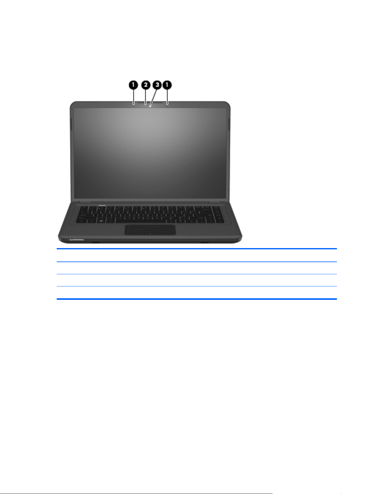
Display components
Item Component Description
(1) Internal microphones (2) Record sound.
(2) HP TrueVision webcam light On: The HP TrueVision webcam is in use.
(3) HP TrueVision webcam Records video and captures still photographs.
10 Chapter 2 External component identification
Page 21
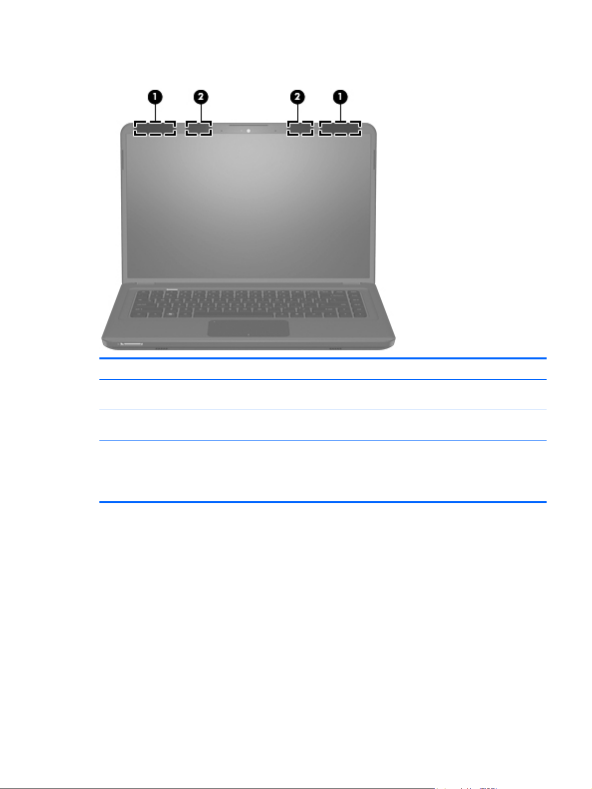
Wireless antenna locations
Item Component Description
(1) WLAN antennas (2)* Send and receive wireless signals to communicate with
wireless local area networks (WLAN).
(2) WWAN antennas (2)* (selected models only) Send and receive wireless signals to communicate with
wireless wide-area networks (WWAN).
*The antennas are not visible from the outside of the computer. For optimal transmission, keep the areas immediately around
the antennas free from obstructions.
To see wireless regulatory notices, refer to the section of the Regulatory, Safety and Environmental Notices that applies to your
country or region. These notices are located in Help and Support.
Top components
11
Page 22
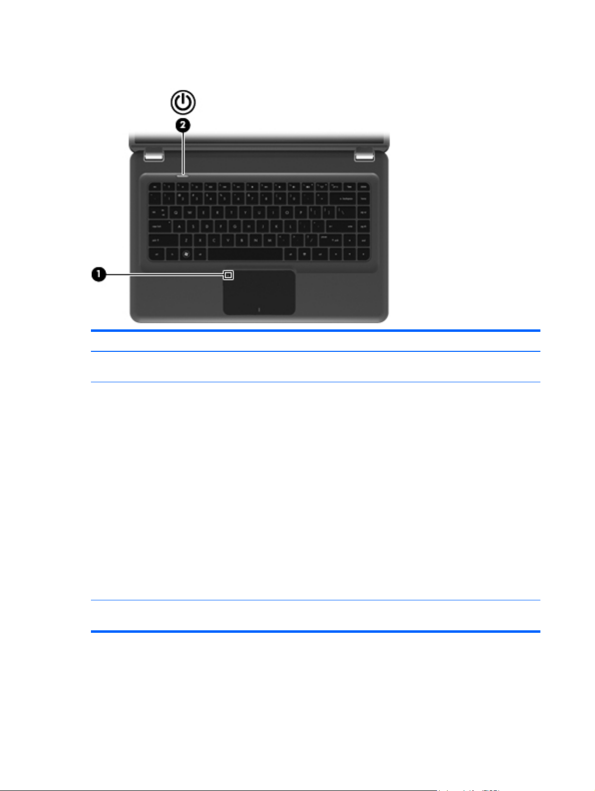
Buttons
Item Component Description
(1) TouchPad on/off button* Turns the TouchPad on and off. Quickly double-tap the
button to turn the TouchPad on and off.
(2) Power button*
*This table describes factory settings. For information about changing factory settings, refer to the user guides located in Help
and Support.
●
When the computer is off, press the button to turn
on the computer.
●
When the computer is on, press the button briefly
to initiate Sleep.
●
When the computer is in the Sleep state, press the
button briefly to exit Sleep.
●
When the computer is in Hibernation, press the
button briefly to exit Hibernation.
If the computer has stopped responding and Windows
shutdown procedures are ineffective, press and hold
the power button for at least 5 seconds to turn off the
computer.
To learn more about your power settings, select Start
> Control Panel > System and Security >
Power Options.
12 Chapter 2 External component identification
Page 23
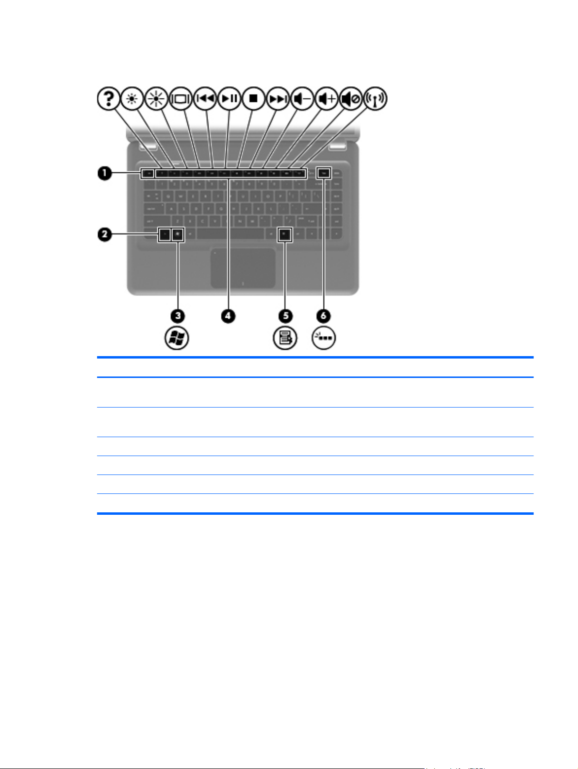
Keys
Item Component Description
(1) esc key Displays system information when pressed in
combination with the fn key.
(2) fn key Displays system information when pressed in
combination with the esc key.
(3) Windows logo key Displays the Windows Start menu.
(4) Action keys Execute frequently used functions.
(5) Windows applications key Displays a shortcut menu for items beneath the pointer.
(6) Keyboard backlight key (select models only) Turns the keyboard backlight on or off.
Top components
13
Page 24
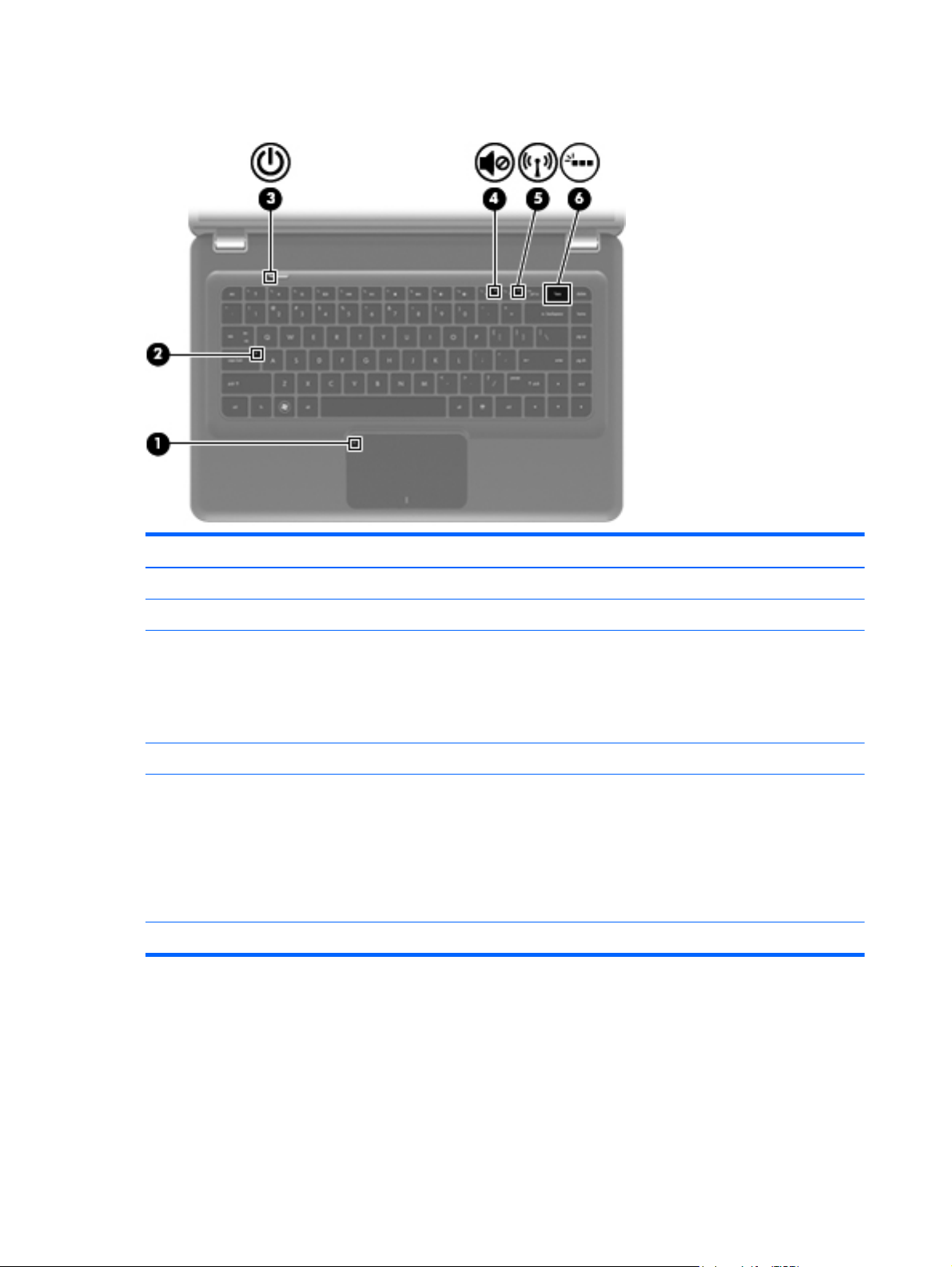
Lights
Item Component Description
(1) TouchPad light On: TouchPad is disabled.
(2) Caps lock light On: Caps Lock is on.
(3) Power light
(4) Mute light On: Speaker sound is off.
(5) Wireless light
(6) Keyboard backlight (select models only) On: The keyboard backlight is enabled.
●
On: The computer is on.
●
Blinking: The computer is in the Sleep state.
NOTE: Another power light is located on the left side
of the computer.
●
White: An integrated wireless device, such as a
wireless local area network (WLAN) device and/
or a Bluetooth device, is on.
NOTE: Wireless devices are enabled at the
factory.
●
Amber: All wireless devices are off.
14 Chapter 2 External component identification
Page 25
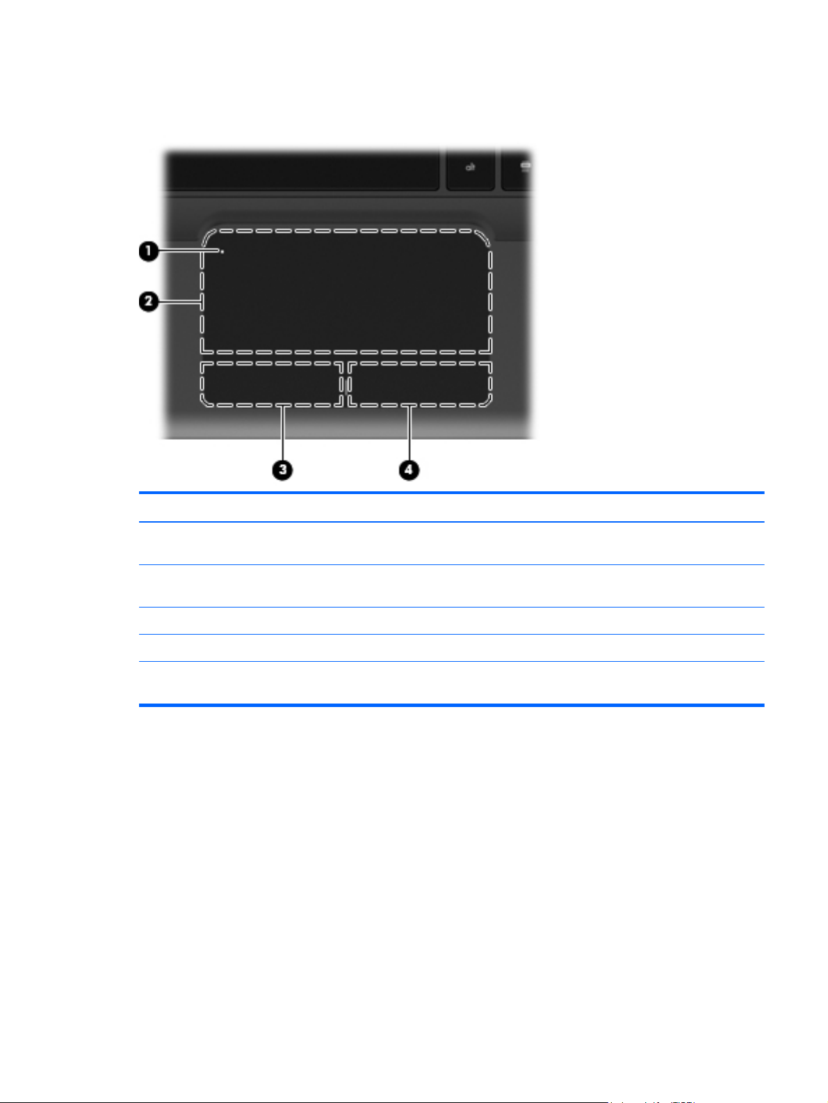
TouchPad
Item Component Description
(1) TouchPad on/off button* Turns the TouchPad on and off. Quickly double-tap the
button to turn the TouchPad on and off.
(2) TouchPad* Moves the pointer and selects or activates items on the
screen.
(3) Left TouchPad button* Functions like the left button on an external mouse.
(4) Right TouchPad button* Functions like the right button on an external mouse.
*This table describes factory settings. To view or change pointing device preferences, select Start > Devices and Printers.
Then, right-click the icon representing your device, and select Mouse settings.
Top components
15
Page 26

Front components
Item Component Description
(1) Digital Media Slot Supports the following optional digital card formats:
(2) Speakers (2) Produce sound.
●
Memory Stick (MS)
●
Memory Stick Pro (MSP)
●
MultiMediaCard (MMC)
●
Secure Digital High Capacity (SDHC) Memory
card (standard and large size)
●
xD-Picture card (XD)
16 Chapter 2 External component identification
Page 27
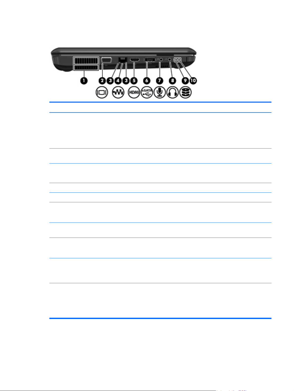
Left-side components
Item Component Description
(1) Vents (2) Enable airflow to cool internal components.
(2) External monitor port Connects an optional external display, such as a
NOTE: The computer fan starts up automatically to
cool internal components and prevent overheating. It is
normal for the internal fan to cycle on and off during
routine operation.
monitor or projector, to the computer.
(3) RJ-45 (network) lights (2)
(4) RJ-45 (network) jack (2) Connects a network cable.
(5) HDMI port Connects an optional HDMI device.
(6) eSATA/USB port Connects high-performance eSATA components, such
(7) Audio-in (microphone) jack Connects an optional computer headset microphone,
(8) Audio-out (headphone) jack Produces sound when connected to optional powered
(9) Drive light
(10) Power light
●
White: The network is connected.
●
Amber: The network is showing activity.
as an eSATA external hard drive, or connects an
optional USB device.
stereo array microphone, or monaural microphone.
stereo speakers, headphones, ear buds, a headset, or
television audio.
●
White: The hard drive is being accessed.
●
Amber: HP ProtectSmart Hard Drive Protection
has temporarily parked the hard drive.
●
On: The computer is on.
●
Blinking: The computer is in the Sleep state.
NOTE: Another power light is located next to the
power button.
Left-side components
17
Page 28
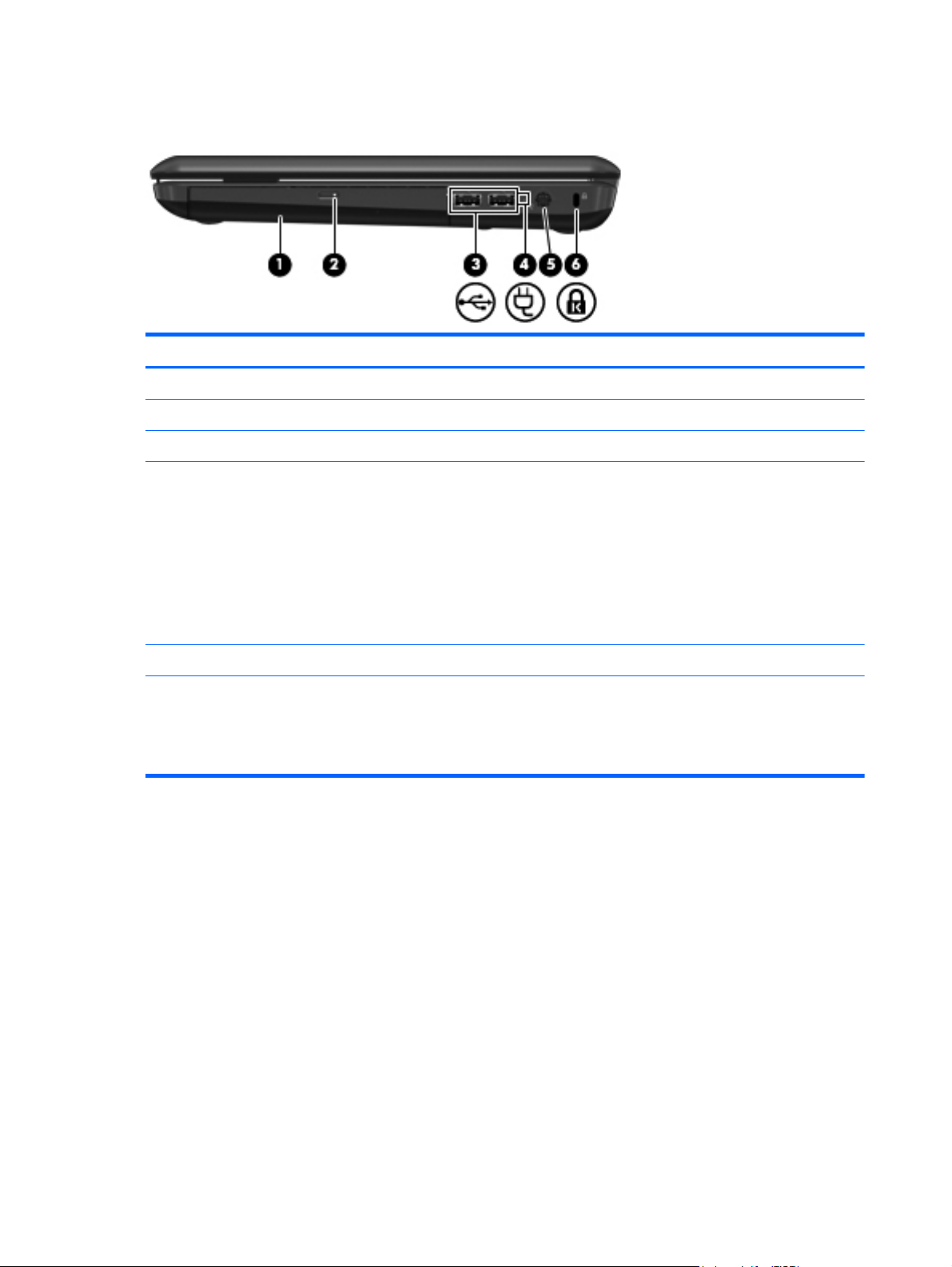
Right-side components
Item Component Description
(1) Optical drive Reads/writes optical discs.
(2) Optical drive light Blinking: The optical drive is being accessed.
(3) USB ports (2) Connect optional USB devices.
(4) Battery light
(5) Power connector Connects an AC adapter.
(6) Security cable slot Attaches an optional security cable to the computer.
●
White: The computer is connected to external
power and the battery is fully charged.
●
Amber: The computer is connected to external
power and the battery is charging.
●
Blinking: A battery that is the only available
power source has reached a low battery level.
When the battery reaches a critical battery level,
the battery light continues to blink.
NOTE: The security cable is designed to act as a
deterrent, but it may not prevent the computer from
being mishandled or stolen.
18 Chapter 2 External component identification
Page 29
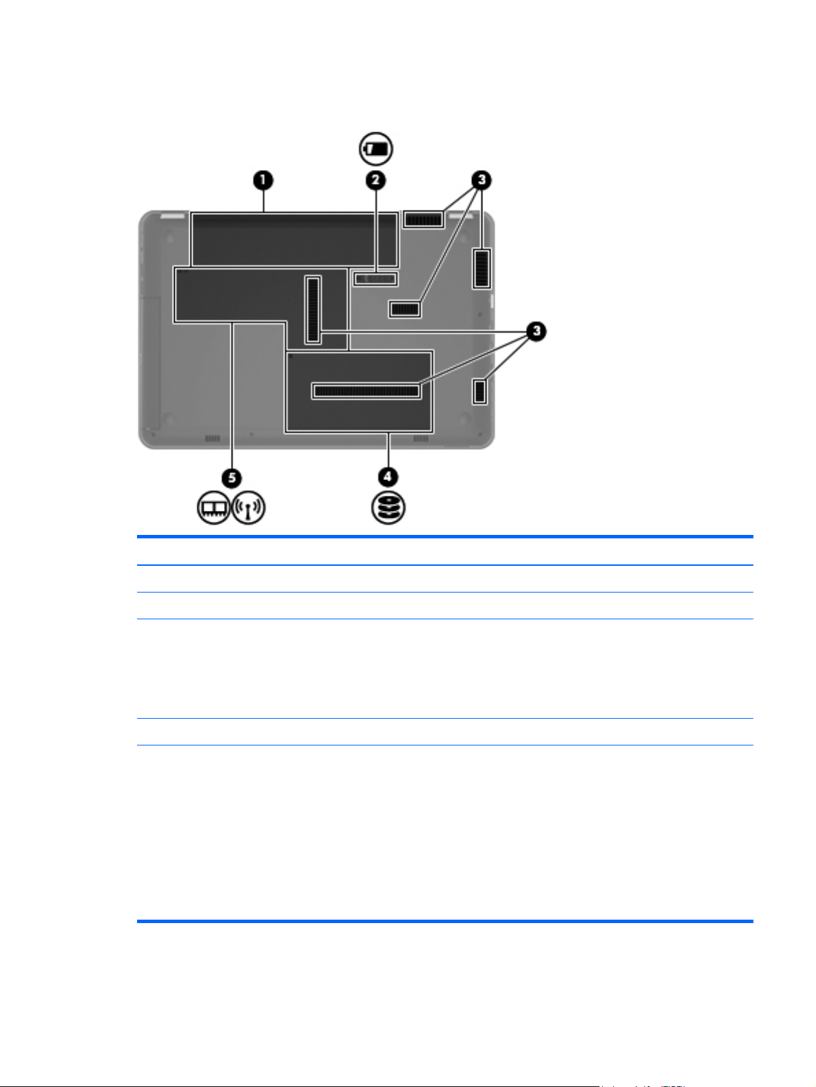
Bottom components
Item Component Description
(1) Battery bay Holds the battery.
(2) Battery release latch Releases the battery from the battery bay.
(3) Vents (6) Enable airflow to cool internal components.
NOTE: The computer fan starts up automatically to
cool internal components and prevent overheating. It is
normal for the internal fan to cycle on and off during
routine operation.
(4) Hard drive bay Holds the hard drive.
(5) Memory/wireless module compartment Holds a wireless LAN module, a wireless WAN
module, and memory modules.
CAUTION: To prevent an unresponsive system,
replace the wireless module with a wireless module
authorized for use by the governmental agency that
regulates wireless devices in your country or region. If
you replace the module and then receive a warning
message, remove the module to restore computer
functionality, and then contact technical support
through Help and Support.
Bottom components
19
Page 30

3 Illustrated parts catalog
20 Chapter 3 Illustrated parts catalog
Page 31

Service tag
When ordering parts or requesting information, provide the computer serial number and model number
provided on the service tag.
Item Component Description
(1) Product name This is the product name affixed to the front of the
computer.
(2) Serial number (s/n) This is an alphanumeric identifier that is unique to each
product.
(3) Part number/Product number (p/n) This number provides specific information about the
product’s hardware components. The part number helps
a service technician determine what components and
parts are needed.
(4) Model description This is the alphanumeric identifier used to locate
documents, drivers, and support for the computer.
(5) Warranty period This number describes the duration of the warranty
period for the computer.
Service tag
21
Page 32

Computer major components
22 Chapter 3 Illustrated parts catalog
Page 33

Item Description Spare part number
(1) Display assembly (includes display panel cable, webcam/microphone module and cable, and 2 WLAN
antenna cables and transceivers):
For use only with computer models equipped with WLAN and WWAN capability (includes 2 WWAN antenna
cables and transceivers):
For use only with computer models not equipped with WWAN capability:
NOTE: See
(2) Keyboard:
Keyboard with backlight (includes keyboard cable and keyboard light cable):
●
14.5-in LED, HD, BrightView display assembly in black cherry 614175-001
●
14.5-in LED, HD, BrightView display assembly in champagne 614178-001
●
14.5-in LED, HD, BrightView display assembly in midnight blue 615385-001
●
14.5-in LED, HD, BrightView display assembly in Sonoma red 614176-001
●
14.5-in LED, HD, BrightView display assembly in shell white 614177-001
●
14.5-in LED, HD, BrightView display assembly in watergarden finish 625046-001
●
14.5-in LED, HD, BrightView display assembly in black cherry 598227-001
●
14.5-in LED, HD, BrightView display assembly in champagne 606872-001
●
14.5-in LED, HD, BrightView display assembly in midnight blue 615384-001
●
14.5-in LED, HD, BrightView display assembly in Sonoma red 606870-001
●
14.5-in LED, HD, BrightView display assembly in shell white 606871-001
Display assembly subcomponents on page 31 for more display component information and spare
part numbers.
Keyboard without backlight (includes keyboard cable):
Keyboard without backlight in watergarden finish (includes keyboard cable):
●
For use in Brazil 606883-201
●
For use in Canada 606883-121
●
For use in Latin America 606883-161
●
For use in the United States 606883-001
●
For use in Brazil 608222-201
●
For use in Canada 608222-121
●
For use in Latin America 608222-161
●
For use in the United States 608222-001
●
For use in Brazil 625047-201
●
For use in Latin America 625047-161
●
For use in the United States 625047-001
Computer major components
23
Page 34

Item Description Spare part number
(3) Top cover (includes TouchPad and cable):
In black cherry 606885-001
In champagne 606888-001
In midnight blue 615386-001
In Sonoma red 606886-001
In shell white 606887-001
In watergarden finish 625048-001
(4) Power button board (includes cable) 607976-001
Cable Kit, includes: 607975-001
(5) Bluetooth module cable
Hard drive cable (not illustrated)
NOTE: See
(6) Bluetooth module
NOTE: The Bluetooth module spare part kit does not include a Bluetooth module cable.
The Bluetooth module cable is included in the Cable Kit, spare part number 607975-001.
(7) Speakers (include cable) 606891-001
(8) USB board (includes cable) 616477-001
Plastics Kit, includes: 606892-001
(9a) Hard drive cover (includes 1 captive screw, secured by a C-clip)
(9b) Memory module/wireless module compartment cover (includes 2 captive screws, secured by C-clips)
NOTE: See
(10) Power connector cable 606890-001
(11) System board (includes replacement thermal material):
For use on computer models equipped with an AMD processor (includes graphics
subsystem with UMA memory)
For use on computer models equipped with an Intel processor (includes graphics
subsystem with discrete memory)
(12) AMD processor (includes replacement thermal material):
Cable Kit on page 33 for more Cable Kit component information.
537921-001
Plastics Kit on page 33 for more Plastics Kit component information.
598225-001
607605-001
AMD Phenom II N970 Quad Core 2.20-GHz processor (2.0-MB L2 cache, 1333-MHz
FSB, 35W, 3.6 gigatransfers/second)
AMD Phenom II N950 Quad Core 2.10-GHz processor (2.0-MB L2 cache, 1333-MHz
FSB, 35W, 3.6 gigatransfers/second)
AMD Phenom II N930 Quad Core 2.00-GHz processor (2.0-MB L2 cache, 1333-MHz
FSB, 35W, 3.6 gigatransfers/second)
24 Chapter 3 Illustrated parts catalog
635496-001
616346-001
594169-001
Page 35

Item Description Spare part number
AMD Phenom II N870 Quad Core 2.30-GHz processor (1.5-MB L2 cache, 1333-MHz
FSB, 35W, 3.6 gigatransfers/second)
AMD Phenom II N850 Triple Core 2.20-GHz processor (1.5-MB L2 cache, 1333-MHz
FSB, 35W, 3.6 gigatransfers/second)
AMD Phenom II N830 Triple Core 2.10-GHz processor (1.5-MB L2 cache, 1333-MHz
FSB, 35W, 3.6 gigatransfers/second)
AMD Phenom II N660 Triple Core 3.00-GHz processor (2.0-MB L2 cache, 1333-MHz
FSB, 35W, 3.6 gigatransfers/second)
AMD Phenom II N640 Triple Core 2.90-GHz processor (1.5-MB L2 cache, 1333-MHz
FSB, 35W, 3.6 gigatransfers/second)
AMD Phenom II N620 Dual Core 2.70-GHz processor (2.0-MB L2 cache, 1333-MHz
FSB, 35W, 3.6 gigatransfers/second)
AMD Phenom II P960 Quad Core 1.80-GHz processor (2.0-MB L2 cache, 1066-MHz
FSB, 25W, 3.6 gigatransfers/second)
AMD Phenom II P940 Quad Core 1.70-GHz processor (2.0-MB L2 cache, 1066-MHz
FSB, 25W, 3.6 gigatransfers/second)
AMD Phenom II P920 Quad Core 1.60-GHz processor (2.0-MB L2 cache, 1066-MHz
FSB, 25W, 3.6 gigatransfers/second)
AMD Phenom II P860 Triple Core 2.00-GHz processor (1.5-MB L2 cache, 1066-MHz
FSB, 25W, 3.6 gigatransfers/second)
635495-001
616345-001
594168-001
635494-001
616344-001
594166-001
634689-001
616336-001
594170-001
634688-001
AMD Phenom II P840 Triple Core 1.90-GHz processor (1.5-MB L2 cache, 1066-MHz
FSB, 25W, 3.6 gigatransfers/second)
AMD Phenom II P820 Triple Core 1.80-GHz processor (1.5-MB L2 cache, 1066-MHz
FSB, 25W, 3.6 gigatransfers/second)
AMD Phenom II P650 Triple Core 2.60-GHz processor (2.0-MB L2 cache, 1066-MHz
FSB, 25W, 3.6 gigatransfers/second)
AMD Turion II N570 Dual Core 2.70-GHz processor (2.0-MB L2 cache, 1066-MHz FSB,
35W, 3.6 gigatransfers/second)
AMD Turion II N550 Dual Core 2.60-GHz processor (2.0-MB L2 cache, 1066-MHz FSB,
35W, 3.6 gigatransfers/second)
AMD Turion II N530 Dual Core 2.50-GHz processor (2.0-MB L2 cache, 1066-MHz FSB,
35W, 3.6 gigatransfers/second)
AMD Turion II P560 Dual Core 2.50-GHz processor (2.0-MB L2 cache, 1066-MHz FSB,
35W, 3.6 gigatransfers/second)
AMD Turion II P540 Dual Core 2.40-GHz processor (2.0-MB L2 cache, 1066-MHz FSB,
25W, 3.6 gigatransfers/second)
AMD Turion II P520 Dual Core 2.30-GHz processor (2.0-MB L2 cache, 1066-MHz FSB,
25W, 3.6 gigatransfers/second)
AMD Athlon II N370 Dual Core 2.50-GHz processor (1.0-MB L2 cache, 1066-MHz FSB,
35W, 3.2 gigatransfers/second)
616335-001
594167-001
634687-001
634690-001
616337-001
594172-001
634691-001
616347-001
594173-001
634686-001
Computer major components
25
Page 36

Item Description Spare part number
AMD Athlon II N350 Dual Core 2.40-GHz processor (1.0-MB L2 cache, 1066-MHz FSB,
35W, 3.2 gigatransfers/second)
AMD Athlon II N330 Dual Core 2.30-GHz processor (1.0-MB L2 cache, 1066-MHz FSB,
35W, 3.2 gigatransfers/second)
AMD Athlon II P360 Dual Core 2.30-GHz processor (1.0-MB L2 cache, 1066-MHz FSB,
35W, 3.2 gigatransfers/second)
AMD Athlon II P340 Dual Core 2.20-GHz processor (1.0-MB L2 cache, 1066-MHz FSB,
25W, 3.2 gigatransfers/second)
AMD Athlon II P320 Dual Core 2.10-GHz processor (1.0-MB L2 cache, 1066-MHz FSB,
25W, 3.2 gigatransfers/second)
AMD Sempron V160 Single Core 2.40-GHz processor (512-KB L2 cache, 1066-MHz
FSB, 25W, 3.2 gigatransfers/second)
AMD Sempron V140 Single Core 2.30-GHz processor (512-KB L2 cache, 1066-MHz
FSB, 25W, 3.2 gigatransfers/second)
AMD Sempron V120 Single Core 2.20-GHz processor (512-KB L2 cache, 1066-MHz
FSB, 25W, 3.2 gigatransfers/second)
Intel processor (includes replacement thermal material):
Intel Core Dual i7-640M 2.80-GHz (SC turbo up to 3.50-GHz), 35W processor (1066-
MHz FSB, 3-MB L3 cache)
616334-001
594164-001
636635-001
616343-001
594165-001
636634-001
616333-001
594171-001
625826-001
Intel Core Dual i7-620M 2.66-GHz (SC turbo up to 3.33-GHz), 35W processor (1066-
MHz FSB, 3-MB L3 cache)
Intel Core Dual i5-580M 2.66-GHz (SC turbo up to 3.33-GHz), 35W processor (1066-
MHz FSB, 3-MB L3 cache)
Intel Core Dual i5-560M 2.66-GHz (SC turbo up to 3.20-GHz), 35W processor (1066-
MHz FSB, 3-MB L3 cache)
Intel Core Dual i5-540M 2.53-GHz (SC turbo up to 3.06-GHz), 35W processor (1066-
MHz FSB, 3-MB L3 cache)
Intel Core Dual i5-520M 2.40-GHz (SC turbo up to 2.93-GHz), 35W processor (1066-
MHz FSB, 3-MB L3 cache)
Intel Core Dual i5-480M 2.66-GHz (SC turbo up to 2.93-GHz), 35W processor (1066-
MHz FSB, 3-MB L3 cache)
Intel Core Dual i5-460M 2.53-GHz (SC turbo up to 2.86-GHz), 35W processor (1066-
MHz FSB, 3-MB L3 cache)
Intel Core Dual i5-450M 2.40-GHz (SC turbo up to 2.86-GHz), 35W processor (1066-
MHz FSB, 3-MB L3 cache)
Intel Core Dual i5-430M 2.26-GHz (SC turbo up to 2.53-GHz), 35W processor (1066-
MHz FSB, 3-MB L3 cache)
Intel Core Dual i3-620M 2.40-GHz, 35W processor (1066-MHz FSB, 3-MB L3 cache) 613584-001
587259-002
625825-001
625824-001
594188-002
594187-002
634693-001
626039-001
613585-001
597624-001
Intel Core Dual i3-390M 2.66-GHz, 35W processor (1066-MHz FSB, 3-MB L3 cache) 634692-001
Intel Core Dual i3-380M 2.53-GHz, 35W processor (1066-MHz FSB, 3-MB L3 cache) 625823-001
26 Chapter 3 Illustrated parts catalog
Page 37

Item Description Spare part number
Intel Core Dual i3-350M 2.26-GHz, 35W processor (1066-MHz FSB, 3-MB L3 cache) 597623-002
Intel Core Dual i3-330M 2.13-GHz, 35W processor (1066-MHz FSB, 3-MB L3 cache) 597622-001
Intel Core2 P6300 2.26-GHz processor (1066-MHz, 3-MB L3 cache) 635500-001
Intel Core2 P6200 2.13-GHz processor (1066-MHz, 3-MB L3 cache) 625831-001
Intel Core2 P6100 2.00-GHz processor (1066-MHz, 3-MB L3 cache) 613587-001
Intel Core2 P6000 1.86-GHz processor (1066-MHz, 3-MB L3 cache) 613586-001
(13) Fan/heat sink assembly (includes replacement thermal material):
For use only on computer models equipped with an AMD processor 606889-001
For use only on computer models equipped with an Intel processor 607590-001
(14) Base enclosure (includes base enclosure bracket, hard drive bay bracket, optical drive
cable bracket, and 4 rubber feet)
Rubber Feet Kit (not illustrated, includes 4 rubber feet) 606894-001
(15) Optical drive:
Blu-ray ROM with LightScribe DVD±RW Super Multi Double-Layer Drive 607601-001
DVD±RW and CD-RW Super Multi Double-Layer Combo Drive with LightScribe 607600-001
(16) Battery:
9-cell, 93-Wh, 2.80-Ah, Li-ion battery 593550-001
6-cell, 62-Wh, 2.80-Ah, Li-ion battery 593562-001
6-cell, 55-Wh, 2.55-Ah, Li-ion battery 593554-001
(17) RTC battery 449137-001
(18) Hard drive:
For use only on computer models equipped with an AMD processor:
For use only on computer models equipped with an Intel processor:
●
1-TB, 5400rpm (includes hard drive isolator) 607968-001
●
500-GB, 7200rpm (does not include hard drive isolator) 603784-001
606884-001
For use on all computer models (includes hard drive isolator):
Hard drive only (hard drive isolator not included) for use on all computer models:
●
1-TB, 5400rpm (includes hard drive isolator) 612855-001
●
750-GB, 5200-rpm 607973-001
●
640-GB, 5400-rpm 607972-001
●
500-GB, 7200-rpm 607971-001
●
320-GB, 7200-rpm 607970-001
●
250-GB, 7200-rpm 607969-001
Computer major components
27
Page 38

Item Description Spare part number
Hard Drive Hardware Kit (not illustrated, includes hard drive isolator)
For use only with 1-TB and 750-GB hard drives 617523-001
For use only with 640-, 500-, 320-, and 250-GB hard drives 607974-001
(19) Memory modules (2, PC3, 10600, 1333-MHz)
4-GB 599092-001
2-GB 598856-001
1-GB 598859-001
(20) HSPA EV-DO WWAN module 531993-001
(21) WLAN module:
●
1-TB, 5200-rpm 603788-001
●
750-GB, 7200-rpm 633252-001
●
750-GB, 5400-rpm 603787-001
●
640-GB, 7200-rpm 621046-001
●
640-GB, 5200-rpm 603785-001
●
500-GB, 5400-rpm 608218-001
For use only with computer models equipped with an Intel processor:
●
Broadcom 43224 802.11a/b/g/n 2×2 WiFi Adapter for use in
Antigua and Barbuda, Barbados, Belize, Canada, the Cayman Islands, Guam,
Puerto Rico, Trinidad and Tobago, the U.S. Virgin Islands, and the United States
582564-001
28 Chapter 3 Illustrated parts catalog
Page 39

Item Description Spare part number
●
Broadcom 43224 802.11a/b/g/n 2×2 WiFi Adapter for use in Afghanistan,
Albania, Algeria, Andorra, Angola, Argentina, Armenia, Aruba, Australia, Austria,
Azerbaijan, the Bahamas, Bahrain, Bangladesh, Barbados, Belarus, Belgium,
Belize, Benin, Bermuda, Bhutan, Bolivia, Bosnia and Herzegovina, Botswana,
Brazil, the British Virgin Islands, Brunei, Bulgaria, Burkina Faso, Burundi, Cambodia,
Cameroon, Cape Verde, the Central African Republic, Chad, Chile, Colombia,
Comoros, the Congo, Costa Rica, Croatia, Cyprus, the Czech Republic, Denmark,
Djibouti, Dominica, the Dominican Republic, East Timor, Ecuador, Egypt,
El Salvador, Equatorial Guinea, Eritrea, Estonia, Ethiopia, Fiji, Finland, France,
French Guiana, Gabon, Gambia, Georgia, Germany, Ghana, Gibraltar, Greece,
Grenada, Guadeloupe, Guatemala, Guinea, Guinea-Bissau, Guyana, Haiti,
Honduras, Hong Kong, Hungary, Iceland, India, Indonesia, Ireland, Italy,
the Ivory Coast, Jamaica, Japan, Jordan, Kazakhstan, Kenya, Kiribati, Kuwait,
Kyrgyzstan, Laos, Latvia, Lebanon, Lesotho, Liberia, Liechtenstein, Lithuania,
Luxembourg, Macedonia, Madagascar, Malawi, Malaysia, the Maldives, Mali,
Malta, the Marshall Islands, Martinique, Mauritania, Mauritius, Mexico, Micronesia,
Monaco, Mongolia, Montenegro, Morocco, Mozambique, Namibia, Nauru, Nepal,
the Nether Antilles, the Netherlands, New Zealand, Nicaragua, Niger, Nigeria,
Norway, Oman, Pakistan, Palau, Panama, Papua New Guinea, Paraguay,
the People’s Republic of China, Peru, the Philippines, Poland, Portugal, Qatar,
the Republic of Moldova, Romania, Russia, Rwanda, Samoa, San Marino,
Sao Tome and Principe, Saudi Arabia, Senegal, Serbia, the Seychelles,
Sierra Leone, Singapore, Slovakia, Slovenia, the Solomon Islands, Somalia,
South Africa, South Korea, Spain, Sri Lanka, St. Kitts and Nevis, St. Lucia,
St. Vincent, Suriname, Swaziland, Sweden, Switzerland, Taiwan, Tajikistan,
Tanzania, Thailand, Togo, Tonga, Tunisia, Turkey, Turkmenistan, Tuvalu, Uganda,
Ukraine, the United Arab Emirates, the United Kingdom, Uruguay, Uzbekistan,
Vanuatu, Venezuela, Vietnam, Yemen, Zaire, Zambia, and Zimbabwe
582564-002
For use on all computer models:
●
Intel Centrino Advanced-N 6200 802.11a/b/g/n 2×2 WLAN module 572509-001
●
Intel Centrino Wireless-N 1000 802.11b/g/n 1×2 WLAN module 593530-001
●
Intel Centrino Advanced-N + WiMAX 6250 WLAN module 619997-001
●
Atheros 9285G 802.11b/g/n 1×1 WiFi Adapter for use in Antigua and Barbuda,
Barbados, Belize, Canada, the Cayman Islands, Guam, Puerto Rico,
Trinidad and Tobago, the U.S. Virgin Islands, and the United States
580101-001
Computer major components
29
Page 40

Item Description Spare part number
●
Atheros 9285G 802.11b/g/n 1×1 WiFi Adapter for use in Afghanistan, Albania,
Algeria, Andorra, Angola, Argentina, Armenia, Aruba, Australia, Austria,
Azerbaijan, the Bahamas, Bahrain, Bangladesh, Barbados, Belarus, Belgium,
Belize, Benin, Bermuda, Bhutan, Bolivia, Bosnia and Herzegovina, Botswana,
Brazil, the British Virgin Islands, Brunei, Bulgaria, Burkina Faso, Burundi, Cambodia,
Cameroon, Cape Verde, the Central African Republic, Chad, Chile, Colombia,
Comoros, the Congo, Costa Rica, Croatia, Cyprus, the Czech Republic, Denmark,
Djibouti, Dominica, the Dominican Republic, East Timor, Ecuador, Egypt,
El Salvador, Equatorial Guinea, Eritrea, Estonia, Ethiopia, Fiji, Finland, France,
French Guiana, Gabon, Gambia, Georgia, Germany, Ghana, Gibraltar, Greece,
Grenada, Guadeloupe, Guatemala, Guinea, Guinea-Bissau, Guyana, Haiti,
Honduras, Hong Kong, Hungary, Iceland, India, Indonesia, Ireland, Italy,
the Ivory Coast, Jamaica, Japan, Jordan, Kazakhstan, Kenya, Kiribati, Kuwait,
Kyrgyzstan, Laos, Latvia, Lebanon, Lesotho, Liberia, Liechtenstein, Lithuania,
Luxembourg, Macedonia, Madagascar, Malawi, Malaysia, the Maldives, Mali,
Malta, the Marshall Islands, Martinique, Mauritania, Mauritius, Mexico, Micronesia,
Monaco, Mongolia, Montenegro, Morocco, Mozambique, Namibia, Nauru, Nepal,
the Nether Antilles, the Netherlands, New Zealand, Nicaragua, Niger, Nigeria,
Norway, Oman, Pakistan, Palau, Panama, Papua New Guinea, Paraguay,
the People’s Republic of China, Peru, the Philippines, Poland, Portugal, Qatar,
the Republic of Moldova, Romania, Russia, Rwanda, Samoa, San Marino,
Sao Tome and Principe, Saudi Arabia, Senegal, Serbia, the Seychelles,
Sierra Leone, Singapore, Slovakia, Slovenia, the Solomon Islands, Somalia,
South Africa, South Korea, Spain, Sri Lanka, St. Kitts and Nevis, St. Lucia,
St. Vincent, Suriname, Swaziland, Sweden, Switzerland, Taiwan, Tajikistan,
Tanzania, Thailand, Togo, Tonga, Tunisia, Turkey, Turkmenistan, Tuvalu, Uganda,
Ukraine, the United Arab Emirates, the United Kingdom, Uruguay, Uzbekistan,
Vanuatu, Venezuela, Vietnam, Yemen, Zaire, Zambia, and Zimbabwe
580101-002
●
Broadcom 4313 802.11b/g/n 1×1 WiFi Adapter 593836-001
●
Broadcom 4313 802.11b/g/n 1×1 WiFi and 2070 Bluetooth 2.1+EDR Combo
Adapter
●
Ralink RT3090BC4 802.11b/g/n 1×1 WiFi and Bluetooth 2.1+EDR Combo
Adapter
600370-001
602992-001
30 Chapter 3 Illustrated parts catalog
Page 41

Display assembly subcomponents
Item Description Spare part number
(1) Display bezel:
Display assembly subcomponents
31
Page 42

Item Description Spare part number
For use only on computer models with a regular finish 606873-001
For use only on computer models with a watergarden finish 632297-001
(2) Display hinge covers (2) 606881-001
(3) Webcam/microphone module 599420-001
(4) 14.5-in LED, HD, BrightView display panel:
For use only with computer models equipped with WWAN capability 614179-001
For use only with computer models not equipped with WWAN capability 598226-001
(5) Display Hinge Kit (includes left and right display hinges) 606878-001
(6) Display panel cable (includes display panel cable, logo light cable, and webcam/
microphone module cable)
Wireless Antenna Kit, includes: 607584-001
(7) WLAN antenna cables and transceivers
(8) WWAN antenna cables and transceivers
(9) Display enclosure (includes logo light and cable and 2 WLAN transceivers and cables)
In black cherry 606874-001
In champagne 606877-001
In midnight blue 615383-001
In shell white 606875-001
In Sonoma red 606876-001
In watergarden finish 625045-001
606879-001
32 Chapter 3 Illustrated parts catalog
Page 43

Cable Kit
Item Description Spare part number
Cable Kit, includes 607975-001
(1) Bluetooth module cable
(2) Hard drive cable
Plastics Kit
Item Description Spare part number
Plastics Kit 606892-001
(1) Hard drive cover (includes one captive screw, secured by a C-clip)
(2) Memory module/wireless module compartment cover (includes 2 captive screws, secured by C-clips)
Cable Kit
33
Page 44

Mass storage devices
Item Description Spare part number
(1) Hard drive:
For use only on computer models equipped with an AMD processor:
For use only on computer models equipped with an Intel processor:
For use on all computer models (includes hard drive isolator):
Hard drive only for use on all computer models (hard drive isolator not included):
●
1-TB, 5400-rpm (includes hard drive isolator) 607968-001
●
500-GB, 7200-rpm (does not include hard drive isolator) 603784-001
●
1-TB, 5400-rpm (includes hard drive isolator) 612855-001
●
750-GB, 5200-rpm 607973-001
●
640-GB, 5400-rpm 607972-001
●
500-GB, 7200-rpm 607971-001
●
320-GB, 7200-rpm 607970-001
●
250-GB, 7200-rpm 607969-001
●
1-TB, 5200-rpm 603788-001
●
750-GB, 7200-rpm 633252-001
●
750-GB, 5400-rpm 603787-001
●
640-GB, 7200-rpm 621046-001
Hard Drive Hardware Kit (not illustrated, includes hard drive isolator):
●
640-GB, 5200-rpm 603785-001
●
500-GB, 5400-rpm 608218-001
34 Chapter 3 Illustrated parts catalog
Page 45

Item Description Spare part number
For use only with 1-TB and 750-GB hard drives 617523-001
For use only with 640-, 500-, 320-, and 250-GB hard drives 607974-001
(2) Optical drive:
Blu-ray ROM with LightScribe DVD±RW Super Multi Double-Layer Drive 607601-001
DVD±RW and CD-RW Super Multi Double-Layer Combo Drive with LightScribe 607600-001
Miscellaneous parts
Description Spare part number
65-W HP Smart AC adapter 609939-001
Power cord:
For use in Argentina 490371-D01
For use in Brazil 490371-202
For use in Italy 490371-061
For use in the United States and Canada 490371-001
Screw Kit 606893-001
Sequential part number listing
Spare part
number
449137-001 RTC battery
409371-001 Power cord for use in the United States and Canada
409371-061 Power cord for use in Italy
409371-202 Power cord for use in Brazil
409371-D01 Power cord for use in Argentina
531993-001 HSPA EV-DO WWAN module
537921-001 Bluetooth module
572509-001 Intel Centrino Advanced-N 6200 802.11a/b/g/n 2×2 WLAN module
580101-001 Atheros AR9280 802.11a/b/g/n 2×2 WiFi Adapter for use in Antigua and Barbuda, Barbados, Belize,
Description
Canada, the Cayman Islands, Guam, Puerto Rico, Trinidad and Tobago, the U.S. Virgin Islands,
and the United States
Miscellaneous parts
35
Page 46

Spare part
number
580101-002 Atheros AR9280 802.11a/b/g/n 2×2 WiFi Adapter for use in Afghanistan, Albania, Algeria, Andorra,
582564-001 Broadcom 43224 802.11a/b/g/n 2×2 WiFi Adapter for use in Antigua and Barbuda, Barbados,
Description
Angola, Argentina, Armenia, Aruba, Australia, Austria, Azerbaijan, the Bahamas, Bahrain, Bangladesh,
Barbados, Belarus, Belgium, Belize, Benin, Bermuda, Bhutan, Bolivia, Bosnia and Herzegovina,
Botswana, Brazil, the British Virgin Islands, Brunei, Bulgaria, Burkina Faso, Burundi, Cambodia,
Cameroon, Cape Verde, the Central African Republic, Chad, Chile, Colombia, Comoros, the Congo,
Costa Rica, Croatia, Cyprus, the Czech Republic, Denmark, Djibouti, Dominica, the Dominican Republic,
East Timor, Ecuador, Egypt, El Salvador, Equatorial Guinea, Eritrea, Estonia, Ethiopia, Fiji, Finland,
France, French Guiana, Gabon, Gambia, Georgia, Germany, Ghana, Gibraltar, Greece, Grenada,
Guadeloupe, Guatemala, Guinea, Guinea-Bissau, Guyana, Haiti, Honduras, Hong Kong, Hungary,
Iceland, India, Indonesia, Ireland, Italy, the Ivory Coast, Jamaica, Japan, Jordan, Kazakhstan, Kenya,
Kiribati, Kuwait, Kyrgyzstan, Laos, Latvia, Lebanon, Lesotho, Liberia, Liechtenstein, Lithuania, Luxembourg,
Macedonia, Madagascar, Malawi, Malaysia, the Maldives, Mali, Malta, the Marshall Islands,
Martinique, Mauritania, Mauritius, Mexico, Micronesia, Monaco, Mongolia, Montenegro, Morocco,
Mozambique, Namibia, Nauru, Nepal, the Nether Antilles, the Netherlands, New Zealand, Nicaragua,
Niger, Nigeria, Norway, Oman, Pakistan, Palau, Panama, Papua New Guinea, Paraguay,
the People’s Republic of China, Peru, the Philippines, Poland, Portugal, Qatar, the Republic of Moldova,
Romania, Russia, Rwanda, Samoa, San Marino, Sao Tome and Principe, Saudi Arabia, Senegal, Serbia,
the Seychelles, Sierra Leone, Singapore, Slovakia, Slovenia, the Solomon Islands, Somalia, South Africa,
South Korea, Spain, Sri Lanka, St. Kitts and Nevis, St. Lucia, St. Vincent, Suriname, Swaziland, Sweden,
Switzerland, Taiwan, Tajikistan, Tanzania, Thailand, Togo, Tonga, Tunisia, Turkey, Turkmenistan, Tuvalu,
Uganda, Ukraine, the United Arab Emirates, the United Kingdom, Uruguay, Uzbekistan, Vanuatu,
Venezuela, Vietnam, Yemen, Zaire, Zambia, and Zimbabwe
Belize, Canada, the Cayman Islands, Guam, Puerto Rico, Trinidad and Tobago, the U.S. Virgin Islands,
and the United States
582564-002 Broadcom 43224 802.11a/b/g/n 2×2 WiFi Adapter for use in Afghanistan, Albania, Algeria, Andorra,
Angola, Argentina, Armenia, Aruba, Australia, Austria, Azerbaijan, the Bahamas, Bahrain, Bangladesh,
Barbados, Belarus, Belgium, Belize, Benin, Bermuda, Bhutan, Bolivia, Bosnia and Herzegovina,
Botswana, Brazil, the British Virgin Islands, Brunei, Bulgaria, Burkina Faso, Burundi, Cambodia,
Cameroon, Cape Verde, the Central African Republic, Chad, Chile, Colombia, Comoros, the Congo,
Costa Rica, Croatia, Cyprus, the Czech Republic, Denmark, Djibouti, Dominica, the Dominican Republic,
East Timor, Ecuador, Egypt, El Salvador, Equatorial Guinea, Eritrea, Estonia, Ethiopia, Fiji, Finland,
France, French Guiana, Gabon, Gambia, Georgia, Germany, Ghana, Gibraltar, Greece, Grenada,
Guadeloupe, Guatemala, Guinea, Guinea-Bissau, Guyana, Haiti, Honduras, Hong Kong, Hungary,
Iceland, India, Indonesia, Ireland, Italy, the Ivory Coast, Jamaica, Japan, Jordan, Kazakhstan, Kenya,
Kiribati, Kuwait, Kyrgyzstan, Laos, Latvia, Lebanon, Lesotho, Liberia, Liechtenstein, Lithuania, Luxembourg,
Macedonia, Madagascar, Malawi, Malaysia, the Maldives, Mali, Malta, the Marshall Islands,
Martinique, Mauritania, Mauritius, Mexico, Micronesia, Monaco, Mongolia, Montenegro, Morocco,
Mozambique, Namibia, Nauru, Nepal, the Nether Antilles, the Netherlands, New Zealand, Nicaragua,
Niger, Nigeria, Norway, Oman, Pakistan, Palau, Panama, Papua New Guinea, Paraguay,
the People’s Republic of China, Peru, the Philippines, Poland, Portugal, Qatar, the Republic of Moldova,
Romania, Russia, Rwanda, Samoa, San Marino, Sao Tome and Principe, Saudi Arabia, Senegal, Serbia,
the Seychelles, Sierra Leone, Singapore, Slovakia, Slovenia, the Solomon Islands, Somalia, South Africa,
South Korea, Spain, Sri Lanka, St. Kitts and Nevis, St. Lucia, St. Vincent, Suriname, Swaziland, Sweden,
Switzerland, Taiwan, Tajikistan, Tanzania, Thailand, Togo, Tonga, Tunisia, Turkey, Turkmenistan, Tuvalu,
Uganda, Ukraine, the United Arab Emirates, the United Kingdom, Uruguay, Uzbekistan, Vanuatu,
Venezuela, Vietnam, Yemen, Zaire, Zambia, and Zimbabwe
587259-002 Intel Core Dual i7-620M 2.66-GHz (SC turbo up to 3.33-GHz), 35W processor (1066-MHz FSB, 3-MB L3
cache; includes replacement thermal material)
593530-001 Intel Centrino Wireless-N 1000 802.11b/g/n 1×2 WLAN module
593550-001 9-cell, 93-Wh, 2.80-Ah, Li-ion battery
36 Chapter 3 Illustrated parts catalog
Page 47

Spare part
number
593554-001 6-cell, 55-Wh, 2.55-Ah, Li-ion battery
593562-001 6-cell, 62-Wh, 2.80-Ah, Li-ion battery
593836-001 Broadcom 4313 802.11b/g/n 11 WiFi Adapter
594164-001 AMD Athlon II N330 Dual Core 2.30-GHz processor (1.0-MB L2 cache, 1066-MHz FSB, 35W, 3.2
594165-001 AMD Athlon II P320 Dual Core 2.10-GHz processor (1.0-MB L2 cache, 1066-MHz FSB, 25W, 3.2
594166-001 AMD Phenom II N620 Dual Core 2.70-GHz processor (2.0-MB L2 cache, 1333-MHz FSB, 35W, 3.6
594167-001 AMD Phenom II P820 Triple Core 1.80-GHz processor (1.5-MB L2 cache, 1066-MHz FSB, 25W, 3.6
594168-001 AMD Phenom II N830 Triple Core 2.10-GHz processor (1.5-MB L2 cache, 1333-MHz FSB, 35W, 3.6
594169-001 AMD Phenom II N930 Quad Core 2.00-GHz processor (2.0-MB L2 cache, 1333-MHz FSB, 35W, 3.6
594170-001 AMD Phenom II P920 Quad Core 1.60-GHz processor (2.0-MB L2 cache, 1066-MHz FSB, 25W, 3.6
Description
gigatransfers/second; includes replacement thermal material)
gigatransfers/second; includes replacement thermal material)
gigatransfers/second; includes replacement thermal material)
gigatransfers/second; includes replacement thermal material)
gigatransfers/second; includes replacement thermal material)
gigatransfers/second; includes replacement thermal material)
gigatransfers/second; includes replacement thermal material)
594171-001 AMD Sempron V120 Single Core 2.20-GHz processor (512-KB L2 cache, 1066-MHz FSB, 25W, 3.2
gigatransfers/second; includes replacement thermal material)
594172-001 AMD Turion II N530 Dual Core 2.50-GHz processor (2.0-MB L2 cache, 1066-MHz FSB, 35W, 3.6
gigatransfers/second; includes replacement thermal material)
594173-001 AMD Turion II P520 Dual Core 2.30-GHz processor (2.0-MB L2 cache, 1066-MHz FSB, 25W, 3.6
gigatransfers/second; includes replacement thermal material)
594187-002 Intel Core Dual i5-520M 2.40-GHz (SC turbo up to 2.93-GHz), 35W processor (1066-MHz FSB, 3-MB L3
cache; includes replacement thermal material)
594188-002 Intel Core Dual i5-540M 2.53-GHz (SC turbo up to 3.06-GHz), 35W processor (1066-MHz FSB, 3-MB L3
cache; includes replacement thermal material)
597622-001 Intel Core Dual i3-330M 2.13-GHz, 35W processor (1066-MHz FSB, 3-MB L3 cache; includes
replacement thermal material)
597623-002 Intel Core Dual i3-350M 2.26-GHz, 35W processor (1066-MHz FSB, 3-MB L3 cache; includes
replacement thermal material)
597624-001 Intel Core Dual i5-430M 2.26-GHz (SC turbo up to 2.53-GHz), 35W processor (1066-MHz FSB, 3-MB L3
cache; includes replacement thermal material)
598225-001 System board for use on computer models equipped with an AMD processor (includes graphics subsystem
with UMA memory and replacement thermal material)
598226-001 14.5-in LED, HD, BrightView display panel for use only with computer models not equipped with WWAN
capability
598227-001 14.5-in LED, HD, BrightView display assembly for use only with computer models not equipped with
WWAN capability in black cherry
598856-001 2-GB memory module (PC3, 10600, 1333-MHz)
Sequential part number listing
37
Page 48

Spare part
number
598859-001 1-GB memory module (PC3, 10600, 1333-MHz)
599092-001 4-GB memory module (PC3, 10600, 1333-MHz)
599420-001 Webcam/microphone module
600370-001 Broadcom 4313 802.11b/g/n 1×1 WiFi and 2070 Bluetooth 2.1+EDR Combo Adapter
602992-001 Ralink RT3090BC4 802.11b/g/n 1×1 WiFi and Bluetooth 2.1+EDR Combo Adapter
603784-001 500-GB, 7200-rpm hard drive for use only on computer models equipped with an AMD processor (does
603785-001 640-GB, 5400-rpm hard drive for use on all computer models (does not include hard drive isolator)
603787-001 750-GB, 5200-rpm hard drive for use on all computer models (does not include hard drive isolator)
603788-001 1-TB, 5200-rpm hard drive for use on all computer models (does not include hard drive isolator)
606870-001 14.5-in LED, HD, BrightView display assembly for use only with computer models not equipped with
606871-001 14.5-in LED, HD, BrightView display assembly for use only with computer models not equipped with
606872-001 14.5-in LED, HD, BrightView display assembly for use only with computer models not equipped with
Description
not include hard drive isolator)
WWAN capability in Sonoma red
WWAN capability in shell white
WWAN capability in champagne
606873-001 Display bezel
606874-001 Display enclosure in black cherry (includes logo light and cable and 2 WLAN transceivers and cables)
606875-001 Display enclosure in shell white (includes logo light and cable and 2 WLAN transceivers and cables)
606876-001 Display enclosure in Sonoma red (includes logo light and cable and 2 WLAN transceivers and cables)
606877-001 Display enclosure in champagne (includes logo light and cable and 2 WLAN transceivers and cables)
606878-001 Display Hinge Kit (includes left and right display hinges)
606879-001 Display panel cable (includes display panel cable, logo light cable, and webcam/microphone module
cable)
606881-001 Display hinge covers
606883-001 Keyboard with backlight for use in the United States (includes keyboard cable and backlight cable)
606883-121 Keyboard with backlight for use in Canada (includes keyboard cable and backlight cable)
606883-161 Keyboard with backlight for use in Latin America (includes keyboard cable and backlight cable)
606883-201 Keyboard with backlight for use in Brazil (includes keyboard cable and backlight cable)
606884-001 Base enclosure (includes base enclosure bracket, hard drive bay bracket, optical drive cable bracket, and
4 rubber feet)
606885-001 Top cover in black cherry (includes TouchPad and cable)
606886-001 Top cover in Sonoma red (includes TouchPad and cable)
606887-001 Top cover in shell white (includes TouchPad and cable)
38 Chapter 3 Illustrated parts catalog
Page 49

Spare part
number
606888-001 Top cover in champagne (includes TouchPad and cable)
606889-001 Fan/heat sink assembly for use only on computer models equipped with an AMD processor (includes
606890-001 Power connector cable
606891-001 Speakers (include cable)
606892-001 Plastics Kit
Description
replacement thermal material)
NOTE: See
606893-001 Screw Kit
606894-001 Rubber Feet Kit (includes 4 rubber feet)
607584-001 Wireless Antenna Kit
607590-001 Fan/heat sink assembly for use only on computer models equipped with an Intel processor (includes
replacement thermal material)
607600-001 DVD±RW and CD-RW Super Multi Double-Layer Combo Drive with LightScribe
607601-001 Blu-ray ROM with LightScribe DVD±RW Super Multi Double-Layer Drive
607605-001 System board for use on computer models equipped with an Intel processor (includes graphics subsystem
with discrete memory; includes replacement thermal material)
607968-001 1-TB, 5400-rpm hard drive for use only on computer models equipped with an AMD processor (includes
hard drive isolator)
607969-001 250-GB, 7200-rpm hard drive for use on all computer models (includes hard drive isolator)
607970-001 320-GB, 7200-rpm hard drive for use on all computer models (includes hard drive isolator)
607971-001 500-GB, 7200-rpm hard drive for use on all computer models (includes hard drive isolator)
607972-001 640-GB, 5400-rpm hard drive for use on all computer models (includes hard drive isolator)
607973-001 750-GB, 5200-rpm hard drive for use on all computer models (includes hard drive isolator)
Plastics Kit on page 33 for more Plastics Kit component information.
607974-001 Hard Drive Hardware Kit for use only with 640-, 500-, 320-, and 250-GB hard drives (includes hard drive
isolator)
607975-001 Cable Kit
NOTE: See
607976-001 Power button board (includes cable)
608218-001 500-GB, 5400-rpm hard drive for use only on computer models equipped with an Intel processor (does
not include hard drive isolator)
608222-001 Keyboard without backlight for use in the United States (includes keyboard cable)
608222-121 Keyboard without backlight for use in Canada (includes keyboard cable)
608222-161 Keyboard without backlight for use in Latin America (includes keyboard cable)
608222-201 Keyboard without backlight for use in Brazil (includes keyboard cable)
Cable Kit on page 33 for more Cable Kit component information.
Sequential part number listing
39
Page 50

Spare part
number
609939-001 65-W HP Smart AC adapter
612855-001 1-TB, 5400-rpm hard drive for use only on computer models equipped with an Intel processor (includes
613584-001 Intel Core Dual i3-620M 2.40-GHz, 35W processor (1066-MHz FSB, 3-MB L3 cache; includes
613585-001 Intel Core Dual i5-450M 2.40-GHz (SC turbo up to 2.86-GHz), 35W processor (1066-MHz FSB, 3-MB L3
613586-001 Intel Core2 P6000 1.86-GHz processor (1066-MHz, 3-MB L3 cache; includes replacement thermal
613587-001 Intel Core2 P6100 2.00-GHz processor (1066-MHz, 3-MB L3 cache; includes replacement thermal
614175-001 14.5-in LED, HD, BrightView display assembly for use only with computer models equipped with WLAN
614176-001 14.5-in LED, HD, BrightView display assembly for use only with computer models equipped with WLAN
614177-001 14.5-in LED, HD, BrightView display assembly for use only with computer models equipped with WLAN
Description
hard drive isolator)
replacement thermal material)
cache; includes replacement thermal material)
material)
material)
and WWAN capability in black cherry (includes display panel cable, webcam/microphone module and
cable, 2 WLAN antenna cables and transceivers, and 2 WWAN antenna cables and transceivers)
and WWAN capability in Sonoma red (includes display panel cable, webcam/microphone module and
cable, 2 WLAN antenna cables and transceivers, and 2 WWAN antenna cables and transceivers)
and WWAN capability in shell white (includes display panel cable, webcam/microphone module and
cable, 2 WLAN antenna cables and transceivers, and 2 WWAN antenna cables and transceivers)
614178-001 14.5-in LED, HD, BrightView display assembly for use only with computer models equipped with WLAN
and WWAN capability in champagne (includes display panel cable, webcam/microphone module and
cable, 2 WLAN antenna cables and transceivers, and 2 WWAN antenna cables and transceivers)
614179-001 14.5-in LED, HD, BrightView display panel for use only with computer models equipped with WWAN
capability
615383-001 Display enclosure in midnight blue (includes logo light and cable and 2 WLAN transceivers and cables)
615384-001 14.5-in LED, HD, BrightView display assembly for use only with computer models not equipped with
WWAN capability in midnight blue
615385-001 14.5-in LED, HD, BrightView display assembly for use only with computer models equipped with WLAN
and WWAN capability in midnight blue (includes display panel cable, webcam/microphone module and
cable, 2 WLAN antenna cables and transceivers, and 2 WWAN antenna cables and transceivers)
615386-001 Top cover in midnight blue (includes TouchPad and cable)
616333-001 AMD Sempron V140 Single Core 2.30-GHz processor (512-KB L2 cache, 1066-MHz FSB, 25W, 3.2
gigatransfers/second; includes replacement thermal material)
616334-001 AMD Athlon II N350 Dual Core 2.40-GHz processor (1.0-MB L2 cache, 1066-MHz FSB, 35W, 3.2
gigatransfers/second; includes replacement thermal material)
616335-001 AMD Phenom II P840 Triple Core 1.90-GHz processor (1.5-MB L2 cache, 1066-MHz FSB, 25W, 3.6
gigatransfers/second; includes replacement thermal material)
616336-001 AMD Phenom II P940 Quad Core 1.70-GHz processor (2.0-MB L2 cache, 1066-MHz FSB, 25W, 3.6
gigatransfers/second; includes replacement thermal material)
40 Chapter 3 Illustrated parts catalog
Page 51

Spare part
number
616337-001 AMD Turion II N550 Dual Core 2.60-GHz processor (2.0-MB L2 cache, 1066-MHz FSB, 35W, 3.6
616343-001 AMD Athlon II P340 Dual Core 2.20-GHz processor (1.0-MB L2 cache, 1066-MHz FSB, 25W, 3.2
616344-001 AMD Phenom II N640 Triple Core 2.90-GHz processor (1.5-MB L2 cache, 1333-MHz FSB, 35W, 3.6
616345-001 AMD Phenom II N850 Triple Core 2.20-GHz processor (1.5-MB L2 cache, 1333-MHz FSB, 35W, 3.6
616346-001 AMD Phenom II N950 Quad Core 2.10-GHz processor (2.0-MB L2 cache, 1333-MHz FSB, 35W, 3.6
616347-001 AMD Turion II P540 Dual Core 2.40-GHz processor (2.0-MB L2 cache, 1066-MHz FSB, 25W, 3.6
616477-001 USB board (includes cable)
617523-001 Hard Drive Hardware Kit for use only with 1-TB and 750-GB hard drives (includes hard drive isolator)
619997-001 Intel Centrino Advanced-N + WiMAX 6250 WLAN module
621046-001 640-GB, 7200-rpm hard drive for use on all computer models (does not include hard drive isolator)
Description
gigatransfers/second; includes replacement thermal material)
gigatransfers/second; includes replacement thermal material)
gigatransfers/second; includes replacement thermal material)
gigatransfers/second; includes replacement thermal material)
gigatransfers/second; includes replacement thermal material)
gigatransfers/second; includes replacement thermal material)
615045-001 Display enclosure in watergarden finish (includes logo light and cable and 2 WLAN transceivers and
cables)
625046-001 14.5-in LED, HD, BrightView display assembly for use only with computer models equipped with WLAN
and WWAN capability in watergarden finish (includes display panel cable, webcam/microphone module
and cable, 2 WLAN antenna cables and transceivers, and 2 WWAN antenna cables and transceivers)
625047-001 Keyboard without backlight in watergarden finish for use in the United States (includes keyboard cable)
625047-161 Keyboard without backlight in watergarden finish for use in Latin America (includes keyboard cable)
625047-201 Keyboard without backlight in watergarden finish for use in Brazil (includes keyboard cable)
625048-001 Top cover in watergarden finish (includes TouchPad and cable)
625823-001 Intel Core Dual i3-380M 2.53-GHz, 35W processor (1066-MHz FSB, 3-MB L3 cache; includes
replacement thermal material)
625824-001 Intel Core Dual i5-560M 2.66-GHz (SC turbo up to 3.20-GHz), 35W processor (1066-MHz FSB, 3-MB L3
cache; includes replacement thermal material)
625825-001 Intel Core Dual i5-580M 2.66-GHz (SC turbo up to 3.33-GHz), 35W processor (1066-MHz FSB, 3-MB L3
cache; includes replacement thermal material)
625826-001 Intel Core Dual i7-640M 2.80-GHz (SC turbo up to 3.50-GHz), 35W processor (1066-MHz FSB, 3-MB L3
cache; includes replacement thermal material)
625831-001 Intel Core2 P6200 2.13-GHz processor (1066-MHz, 3-MB L3 cache; includes replacement thermal
material)
626039-001 Intel Core Dual i5-460M 2.53-GHz (SC turbo up to 2.86-GHz), 35W processor (1066-MHz FSB, 3-MB L3
cache; includes replacement thermal material)
632297-001 Display bezel in watergarden finish
Sequential part number listing
41
Page 52

Spare part
number
633252-001 750-GB, 7200-rpm hard drive for use on all computer models (does not include hard drive isolator)
634686-001 AMD Athlon II N370 Dual Core 2.50-GHz processor (1.0-MB L2 cache, 1066-MHz FSB, 35W, 3.2
634687-001 AMD Phenom II P650 Triple Core 2.60-GHz processor (2.0-MB L2 cache, 1333-MHz FSB, 25W, 3.6
634688-001 AMD Phenom II P860 Triple Core 2.00-GHz processor (1.5-MB L2 cache, 1333-MHz FSB, 25W, 3.6
634689-001 AMD Phenom II P960 Triple Core 1.80-GHz processor (2.0-MB L2 cache, 1333-MHz FSB, 25W, 3.6
634690-001 AMD Turion II N750 Dual Core 2.70-GHz processor (2.0-MB L2 cache, 1066-MHz FSB, 35W, 3.6
634691-001 AMD Turion II P560 Dual Core 2.50-GHz processor (2.0-MB L2 cache, 1066-MHz FSB, 35W, 3.6
634692-001 Intel Core Dual i3-390M 2.66-GHz, 35W processor (1066-MHz FSB, 3-MB L3 cache; includes
634693-001 Intel Core Dual i5-480M 2.66-GHz (SC turbo up to 2.93-GHz), 35W processor (1066-MHz FSB, 3-MB L3
Description
gigatransfers/second; includes replacement thermal material)
gigatransfers/second; includes replacement thermal material)
gigatransfers/second; includes replacement thermal material)
gigatransfers/second; includes replacement thermal material)
gigatransfers/second; includes replacement thermal material)
gigatransfers/second; includes replacement thermal material)
replacement thermal material)
cache; includes replacement thermal material)
635494-001 AMD Phenom II N660 Triple Core 3.00-GHz processor (2.0-MB L2 cache, 1333-MHz FSB, 25W, 3.6
gigatransfers/second; includes replacement thermal material)
635495-001 AMD Phenom II N870 Triple Core 2.30-GHz processor (1.5-MB L2 cache, 1333-MHz FSB, 25W, 3.6
gigatransfers/second; includes replacement thermal material)
635496-001 AMD Phenom II N970 Triple Core 2.20-GHz processor (2.0-MB L2 cache, 1333-MHz FSB, 25W, 3.6
gigatransfers/second; includes replacement thermal material)
635500-001 Intel Core2 P6300 2.26-GHz processor (1066-MHz, 3-MB L3 cache; includes replacement thermal
material)
636634-001 AMD Sempron V160 Single Core 2.40-GHz processor (512-KB L2 cache, 1066-MHz FSB, 25W, 3.2
gigatransfers/second)
636635-001 AMD Athlon II P360 Dual Core 2.30-GHz processor (1.0-MB L2 cache, 1066-MHz FSB, 35W, 3.2
gigatransfers/second; includes replacement thermal material)
42 Chapter 3 Illustrated parts catalog
Page 53

4 Removal and replacement
procedures
Preliminary replacement requirements
Tools required
You will need the following tools to complete the removal and replacement procedures:
●
Flat-bladed screwdriver
●
Magnetic screwdriver
●
Phillips P0 and P1 screwdrivers
Service considerations
The following sections include some of the considerations that you must keep in mind during
disassembly and assembly procedures.
NOTE: As you remove each subassembly from the computer, place the subassembly (and all
accompanying screws) away from the work area to prevent damage.
Plastic parts
CAUTION: Using excessive force during disassembly and reassembly can damage plastic parts. Use
care when handling the plastic parts. Apply pressure only at the points designated in the maintenance
instructions.
Cables and connectors
CAUTION: When servicing the computer, be sure that cables are placed in their proper locations
during the reassembly process. Improper cable placement can damage the computer.
Cables must be handled with extreme care to avoid damage. Apply only the tension required to unseat
or seat the cables during removal and insertion. Handle cables by the connector whenever possible. In
all cases, avoid bending, twisting, or tearing cables. Be sure that cables are routed in such a way that
they cannot be caught or snagged by parts being removed or replaced. Handle flex cables with
extreme care; these cables tear easily.
Preliminary replacement requirements
43
Page 54

Drive handling
CAUTION: Drives are fragile components that must be handled with care. To prevent damage to the
computer, damage to a drive, or loss of information, observe these precautions:
Before removing or inserting a hard drive, shut down the computer. If you are unsure whether the
computer is off or in Hibernation, turn the computer on, and then shut it down through the operating
system.
Before handling a drive, be sure that you are discharged of static electricity. While handling a drive,
avoid touching the connector.
Before removing a diskette drive or optical drive, be sure that a diskette or disc is not in the drive and
be sure that the optical drive tray is closed.
Handle drives on surfaces covered with at least one inch of shock-proof foam.
Avoid dropping drives from any height onto any surface.
After removing a hard drive, an optical drive, or a diskette drive, place it in a static-proof bag.
Avoid exposing an internal hard drive to products that have magnetic fields, such as monitors or
speakers.
Avoid exposing a drive to temperature extremes or liquids.
If a drive must be mailed, place the drive in a bubble pack mailer or other suitable form of protective
packaging and label the package “FRAGILE.”
Grounding guidelines
Electrostatic discharge damage
Electronic components are sensitive to electrostatic discharge (ESD). Circuitry design and structure
determine the degree of sensitivity. Networks built into many integrated circuits provide some
protection, but in many cases, ESD contains enough power to alter device parameters or melt silicon
junctions.
A discharge of static electricity from a finger or other conductor can destroy static-sensitive devices or
microcircuitry. Even if the spark is neither felt nor heard, damage may have occurred.
An electronic device exposed to ESD may not be affected at all and can work perfectly throughout a
normal cycle. Or the device may function normally for a while, then degrade in the internal layers,
reducing its life expectancy.
44 Chapter 4 Removal and replacement procedures
Page 55

CAUTION: To prevent damage to the computer when you are removing or installing internal
components, observe these precautions:
Keep components in their electrostatic-safe containers until you are ready to install them.
Before touching an electronic component, discharge static electricity by using the guidelines described
in this section.
Avoid touching pins, leads, and circuitry. Handle electronic components as little as possible.
If you remove a component, place it in an electrostatic-safe container.
The following table shows how humidity affects the electrostatic voltage levels generated by different
activities.
CAUTION: A product can be degraded by as little as 700 V.
Typical electrostatic voltage levels
Relative humidity
Event 10% 40% 55%
Walking across carpet 35,000 V 15,000 V 7,500 V
Walking across vinyl floor 12,000 V 5,000 V 3,000 V
Motions of bench worker 6,000 V 800 V 400 V
Removing DIPS from plastic tube 2,000 V 700 V 400 V
Removing DIPS from vinyl tray 11,500 V 4,000 V 2,000 V
Removing DIPS from Styrofoam 14,500 V 5,000 V 3,500 V
Removing bubble pack from PCB 26,500 V 20,000 V 7,000 V
Packing PCBs in foam-lined box 21,000 V 11,000 V 5,000 V
Preliminary replacement requirements
45
Page 56

Packaging and transporting guidelines
Follow these grounding guidelines when packaging and transporting equipment:
●
To avoid hand contact, transport products in static-safe tubes, bags, or boxes.
●
Protect ESD-sensitive parts and assemblies with conductive or approved containers or packaging.
●
Keep ESD-sensitive parts in their containers until the parts arrive at static-free workstations.
●
Place items on a grounded surface before removing items from their containers.
●
Always be properly grounded when touching a component or assembly.
●
Store reusable ESD-sensitive parts from assemblies in protective packaging or nonconductive
foam.
●
Use transporters and conveyors made of antistatic belts and roller bushings. Be sure that
mechanized equipment used for moving materials is wired to ground and that proper materials
are selected to avoid static charging. When grounding is not possible, use an ionizer to dissipate
electric charges.
Workstation guidelines
Follow these grounding workstation guidelines:
●
Cover the workstation with approved static-shielding material.
●
Use a wrist strap connected to a properly grounded work surface and use properly grounded tools
and equipment.
●
Use conductive field service tools, such as cutters, screwdrivers, and vacuums.
●
When fixtures must directly contact dissipative surfaces, use fixtures made only of static-safe
materials.
●
Keep the work area free of nonconductive materials, such as ordinary plastic assembly aids and
Styrofoam.
●
Handle ESD-sensitive components, parts, and assemblies by the case or PCM laminate. Handle
these items only at static-free workstations.
●
Avoid contact with pins, leads, or circuitry.
●
Turn off power and input signals before inserting or removing connectors or test equipment.
46 Chapter 4 Removal and replacement procedures
Page 57

Equipment guidelines
Grounding equipment must include either a wrist strap or a foot strap at a grounded workstation.
●
When seated, wear a wrist strap connected to a grounded system. Wrist straps are flexible straps
with a minimum of one megohm ±10% resistance in the ground cords. To provide proper ground,
wear a strap snugly against the skin at all times. On grounded mats with banana-plug connectors,
use alligator clips to connect a wrist strap.
●
When standing, use foot straps and a grounded floor mat. Foot straps (heel, toe, or boot straps)
can be used at standing workstations and are compatible with most types of shoes or boots. On
conductive floors or dissipative floor mats, use foot straps on both feet with a minimum of one
megohm resistance between the operator and ground. To be effective, the conductive must be
worn in contact with the skin.
The following grounding equipment is recommended to prevent electrostatic damage:
●
Antistatic tape
●
Antistatic smocks, aprons, and sleeve protectors
●
Conductive bins and other assembly or soldering aids
●
Nonconductive foam
●
Conductive tabletop workstations with ground cords of one megohm resistance
●
Static-dissipative tables or floor mats with hard ties to the ground
●
Field service kits
●
Static awareness labels
●
Material-handling packages
●
Nonconductive plastic bags, tubes, or boxes
●
Metal tote boxes
●
Electrostatic voltage levels and protective materials
The following table lists the shielding protection provided by antistatic bags and floor mats.
Material Use Voltage protection level
Antistatic plastics Bags 1,500 V
Carbon-loaded plastic Floor mats 7,500 V
Metallized laminate Floor mats 5,000 V
Preliminary replacement requirements
47
Page 58

Component replacement procedures
This chapter provides removal and replacement procedures.
There are as many as 68 screws that must be removed, replaced, or loosened when servicing the
computer. Make special note of each screw and screw lock size and location during removal and
replacement.
Service tag
When ordering parts or requesting information, provide the computer serial number and model number
provided on the service tag.
Item Component Description
(1) Product name This is the product name affixed to the front of the
(2) Serial number (s/n) This is an alphanumeric identifier that is unique to each
(3) Part number/Product number (p/n) This number provides specific information about the
48 Chapter 4 Removal and replacement procedures
computer.
product.
product’s hardware components. The part number helps
a service technician determine what components and
parts are needed.
Page 59

Item Component Description
(4) Model description This is the alphanumeric identifier used to locate
(5) Warranty period This number describes the duration of the warranty
Computer feet
The computer feet are adhesive-backed rubber pads. The feet are included in the Rubber Feet Kit, spare
part number 606894-001. There are 4 rubber feet that attach to the base enclosure in the locations
illustrated below.
documents, drivers, and support for the computer.
period for the computer.
Battery
Description Spare part number
9-cell, 93-Wh, 2.80-Ah, Li-ion battery 593550-001
6-cell, 62-Wh, 2.80-Ah, Li-ion battery 593562-001
6-cell, 55-Wh, 2.55-Ah, Li-ion battery 593554-001
Before disassembling the computer, follow these steps:
1. Shut down the computer. If you are unsure whether the computer is off or in Hibernation, turn the
computer on, and then shut it down through the operating system.
2. Disconnect all external devices connected to the computer.
3. Disconnect the power from the computer by first unplugging the power cord from the AC outlet
and then unplugging the AC adapter from the computer.
Component replacement procedures
49
Page 60

Remove the battery:
1. Turn the computer upside down on a flat surface, with the front toward you.
2.
Slide the battery release latch (1) to release the battery.
3. Pivot the front edge of the battery (2) upward.
4. Remove the battery from the computer.
To insert the battery, insert the rear edge of the battery into the battery bay, and pivot the front edge of
the battery downward until it is seated. The battery release latch automatically locks the battery into
place.
Memory module
Description Spare part number
4-GB (PC3, 10600, 1333-MHz) 599092-001
2-GB (PC3, 10600, 1333-MHz) 598856-001
1-GB (PC3, 10600, 1333-MHz) 598859-001
Before removing a memory module, follow these steps:
1. Shut down the computer. If you are unsure whether the computer is off or in Hibernation, turn the
computer on, and then shut it down through the operating system.
2. Disconnect all external devices connected to the computer.
3. Disconnect the power from the computer by first unplugging the power cord from the AC outlet
and then unplugging the AC adapter from the computer.
4. Remove the battery (see
Battery on page 49).
50 Chapter 4 Removal and replacement procedures
Page 61

Remove the memory module:
1. Loosen the two captive screws that secure the memory module/wireless module compartment
cover to the computer.
2. Lift the rear edge of the memory module/wireless module compartment cover until it detaches from
the computer.
3. Remove the memory module/wireless module compartment cover. The memory module/wireless
module compartment cover is included in the Plastics Kit, spare part number 606892-001.
4. Release the memory module shield by folding in back.
Component replacement procedures
51
Page 62

5.
Spread the retaining tabs on each side of the memory module slot to release the memory module.
(The memory module tilts up.)
6. Remove the memory module by pulling it away from the slot at an angle.
Reverse this procedure to install a memory module.
52 Chapter 4 Removal and replacement procedures
Page 63

WLAN module
Description Spare part number
For use only with computer models equipped with an Intel processor:
●
Broadcom 43224 802.11a/b/g/n 2×2 WiFi Adapter for use in Antigua and Barbuda,
Barbados, Belize, Canada, the Cayman Islands, Guam, Puerto Rico, Trinidad and Tobago,
the U.S. Virgin Islands, and the United States
●
Broadcom 43224 802.11a/b/g/n 2×2 WiFi Adapter for use in Afghanistan, Albania,
Algeria, Andorra, Angola, Argentina, Armenia, Aruba, Australia, Austria, Azerbaijan,
the Bahamas, Bahrain, Bangladesh, Barbados, Belarus, Belgium, Belize, Benin, Bermuda,
Bhutan, Bolivia, Bosnia and Herzegovina, Botswana, Brazil, the British Virgin Islands, Brunei,
Bulgaria, Burkina Faso, Burundi, Cambodia, Cameroon, Cape Verde,
the Central African Republic, Chad, Chile, Colombia, Comoros, the Congo, Costa Rica,
Croatia, Cyprus, the Czech Republic, Denmark, Djibouti, Dominica, the Dominican Republic,
East Timor, Ecuador, Egypt, El Salvador, Equatorial Guinea, Eritrea, Estonia, Ethiopia, Fiji,
Finland, France, French Guiana, Gabon, Gambia, Georgia, Germany, Ghana, Gibraltar,
Greece, Grenada, Guadeloupe, Guatemala, Guinea, Guinea-Bissau, Guyana, Haiti, Honduras,
Hong Kong, Hungary, Iceland, India, Indonesia, Ireland, Italy, the Ivory Coast, Jamaica, Japan,
Jordan, Kazakhstan, Kenya, Kiribati, Kuwait, Kyrgyzstan, Laos, Latvia, Lebanon, Lesotho,
Liberia, Liechtenstein, Lithuania, Luxembourg, Macedonia, Madagascar, Malawi, Malaysia,
the Maldives, Mali, Malta, the Marshall Islands, Martinique, Mauritania, Mauritius, Mexico,
Micronesia, Monaco, Mongolia, Montenegro, Morocco, Mozambique, Namibia, Nauru,
Nepal, the Nether Antilles, the Netherlands, New Zealand, Nicaragua, Niger, Nigeria,
Norway, Oman, Pakistan, Palau, Panama, Papua New Guinea, Paraguay,
the People’s Republic of China, Peru, the Philippines, Poland, Portugal, Qatar,
the Republic of Moldova, Romania, Russia, Rwanda, Samoa, San Marino,
Sao Tome and Principe, Saudi Arabia, Senegal, Serbia, the Seychelles, Sierra Leone,
Singapore, Slovakia, Slovenia, the Solomon Islands, Somalia, South Africa, South Korea,
Spain, Sri Lanka, St. Kitts and Nevis, St. Lucia, St. Vincent, Suriname, Swaziland, Sweden,
Switzerland, Taiwan, Tajikistan, Tanzania, Thailand, Togo, Tonga, Tunisia, Turkey,
Turkmenistan, Tuvalu, Uganda, Ukraine, the United Arab Emirates, the United Kingdom,
Uruguay, Uzbekistan, Vanuatu, Venezuela, Vietnam, Yemen, Zaire, Zambia, and Zimbabwe
582564-001
582564-002
●
Intel Centrino Advanced-N 6200 802.11a/b/g/n 2×2 WLAN module 572509-001
●
Intel Centrino Wireless-N 1000 802.11b/g/n 1×2 WLAN module 593530-001
●
Intel Centrino Advanced-N + WiMAX 6250 WLAN module 619997-001
For use on all computer models:
●
Atheros 9285G 802.11b/g/n 1×1 WiFi Adapter for use in Antigua and Barbuda, Barbados,
Belize, Canada, the Cayman Islands, Guam, Puerto Rico, Trinidad and Tobago,
the U.S. Virgin Islands, and the United States
580101-001
Component replacement procedures
53
Page 64

Description Spare part number
●
Atheros 9285G 802.11b/g/n 1×1 WiFi Adapter for use in Afghanistan, Albania, Algeria,
Andorra, Angola, Argentina, Armenia, Aruba, Australia, Austria, Azerbaijan, the Bahamas,
Bahrain, Bangladesh, Barbados, Belarus, Belgium, Belize, Benin, Bermuda, Bhutan, Bolivia,
Bosnia and Herzegovina, Botswana, Brazil, the British Virgin Islands, Brunei, Bulgaria,
Burkina Faso, Burundi, Cambodia, Cameroon, Cape Verde, the Central African Republic,
Chad, Chile, Colombia, Comoros, the Congo, Costa Rica, Croatia, Cyprus,
the Czech Republic, Denmark, Djibouti, Dominica, the Dominican Republic, East Timor,
Ecuador, Egypt, El Salvador, Equatorial Guinea, Eritrea, Estonia, Ethiopia, Fiji, Finland, France,
French Guiana, Gabon, Gambia, Georgia, Germany, Ghana, Gibraltar, Greece, Grenada,
Guadeloupe, Guatemala, Guinea, Guinea-Bissau, Guyana, Haiti, Honduras, Hong Kong,
Hungary, Iceland, India, Indonesia, Ireland, Italy, the Ivory Coast, Jamaica, Japan, Jordan,
Kazakhstan, Kenya, Kiribati, Kuwait, Kyrgyzstan, Laos, Latvia, Lebanon, Lesotho, Liberia,
Liechtenstein, Lithuania, Luxembourg, Macedonia, Madagascar, Malawi, Malaysia,
the Maldives, Mali, Malta, the Marshall Islands, Martinique, Mauritania, Mauritius, Mexico,
Micronesia, Monaco, Mongolia, Montenegro, Morocco, Mozambique, Namibia, Nauru,
Nepal, the Nether Antilles, the Netherlands, New Zealand, Nicaragua, Niger, Nigeria,
Norway, Oman, Pakistan, Palau, Panama, Papua New Guinea, Paraguay,
the People’s Republic of China, Peru, the Philippines, Poland, Portugal, Qatar,
the Republic of Moldova, Romania, Russia, Rwanda, Samoa, San Marino,
Sao Tome and Principe, Saudi Arabia, Senegal, Serbia, the Seychelles, Sierra Leone,
Singapore, Slovakia, Slovenia, the Solomon Islands, Somalia, South Africa, South Korea,
Spain, Sri Lanka, St. Kitts and Nevis, St. Lucia, St. Vincent, Suriname, Swaziland, Sweden,
Switzerland, Taiwan, Tajikistan, Tanzania, Thailand, Togo, Tonga, Tunisia, Turkey,
Turkmenistan, Tuvalu, Uganda, Ukraine, the United Arab Emirates, the United Kingdom,
Uruguay, Uzbekistan, Vanuatu, Venezuela, Vietnam, Yemen, Zaire, Zambia, and Zimbabwe
580101-002
●
Broadcom 4313 802.11b/g/n 1×1 WiFi Adapter 593836-001
●
Broadcom 4313 802.11b/g/n 1×1 WiFi and 2070 Bluetooth 2.1+EDR Combo Adapter 600370-001
●
Ralink RT3090BC4 802.11b/g/n 1×1 WiFi and Bluetooth 2.1+EDR Combo Adapter 602992-001
CAUTION: To prevent an unresponsive system, replace the wireless module only with a wireless
module authorized for use in the computer by the governmental agency that regulates wireless devices
in your country or region. If you replace the module and then receive a warning message, remove the
module to restore device functionality, and then contact technical support.
Before removing the WLAN module, follow these steps:
1. Shut down the computer. If you are unsure whether the computer is off or in Hibernation, turn the
computer on, and then shut it down through the operating system.
2.
Disconnect all external devices connected to the computer.
3. Disconnect the power from the computer by first unplugging the power cord from the AC outlet
and then unplugging the AC adapter from the computer.
4. Remove the battery (see
5. Remove the memory module/wireless module compartment cover (see
Battery on page 49).
Memory module
on page 50).
54 Chapter 4 Removal and replacement procedures
Page 65

Remove the WLAN module:
1. Disconnect the WLAN antenna cables from the terminals on the WLAN module.
NOTE: The 1/black WLAN antenna cable is connected to the WLAN module 1/Main terminal.
The 2/gray WLAN antenna cable is connected to the WLAN module 2/Aux terminal.
2. Remove the two Phillips PM2.0×4.0 screws that secure the WLAN module to the system board.
(The WLAN module tilts up.)
3. Remove the WLAN module by pulling the module away from the slot at an angle.
Component replacement procedures
55
Page 66

NOTE: If the WLAN antennas are not connected to the terminals on the WLAN module, the protective
sleeves must be installed on the antenna connectors, as shown in the following illustration.
Reverse this procedure to install the WLAN module.
WWAN module
Description Spare part number
HSPA EV-DO WWAN module 531993-001
CAUTION: To prevent an unresponsive system, replace the wireless module only with a wireless
module authorized for use in the computer by the governmental agency that regulates wireless devices
in your country or region. If you replace the module and then receive a warning message, remove the
module to restore device functionality, and then contact technical support.
Before removing the WWAN module, follow these steps:
1. Shut down the computer. If you are unsure whether the computer is off or in Hibernation, turn the
computer on, and then shut it down through the operating system.
2. Disconnect all external devices connected to the computer.
3. Disconnect the power from the computer by first unplugging the power cord from the AC outlet
and then unplugging the AC adapter from the computer.
4. Remove the battery (see
5. Remove the memory module/wireless module compartment cover (see
Battery on page 49).
Memory module
on page 50).
56 Chapter 4 Removal and replacement procedures
Page 67

Remove the WWAN module:
1. Disconnect the WWAN antenna cables from the terminals on the WWAN module.
NOTE: The 1/red WWAN antenna cable is connected to the WWAN module 1/Main
terminal. The 2/blue WWAN antenna cable is connected to the WWAN module 2/Aux terminal.
2.
Remove the two Phillips PM2.0×4.0 screws that secure the WWAN module to the system board.
(The WWAN module tilts up.)
3. Remove the WWAN module by pulling the module away from the slot at an angle.
NOTE: If the WWAN antennas are not connected to the terminals on the WWAN module, the
protective sleeves must be installed on the antenna connectors, as shown in the following illustration.
Component replacement procedures
57
Page 68

Reverse this procedure to install the WWAN module.
Hard drive
Description Spare part number
For use only on computer models equipped with an AMD processor:
●
1-TB, 5400-rpm (includes hard drive isolator) 607968-001
●
500-GB, 7200-rpm (does not include hard drive isolator) 603784-001
For use only on computer models equipped with an Intel processor (includes hard drive isolator):
●
1-TB, 5400-rpm 612855-001
For use on all computer models (includes hard drive isolator):
●
750-GB, 5200-rpm 607973-001
●
640-GB, 5400-rpm 607972-001
●
500-GB, 7200-rpm 607971-001
●
320-GB, 7200-rpm 607970-001
●
250-GB, 7200-rpm 607969-001
Hard drive only (hard drive isolator not included) for use on all computer models:
●
1-TB, 5200-rpm 603788-001
●
750-GB, 7200-rpm 633252-001
●
750-GB, 5400-rpm 603787-001
●
640-GB, 7200-rpm 621046-001
●
640-GB, 5200-rpm 603785-001
●
500-GB, 5400-rpm 608218-001
Hard Drive Hardware Kit (includes hard drive isolator)
For use only with 1-TB and 750-GB hard drives 617523-001
For use only with 640-, 500-, 320-, and 250-GB hard drives 607974-001
58 Chapter 4 Removal and replacement procedures
Page 69

Before removing the hard drive, follow these steps:
1. Shut down the computer. If you are unsure whether the computer is off or in Hibernation, turn the
computer on, and then shut it down through the operating system.
2. Disconnect all external devices connected to the computer.
3. Disconnect the power from the computer by first unplugging the power cord from the AC outlet
and then unplugging the AC adapter from the computer.
4. Remove the battery (see
5. Remove the memory module/wireless module compartment cover (see
on page 50).
Remove the hard drive:
1. Loosen the captive screw that secures the hard drive cover to the computer.
Battery on page 49).
Memory module
2. Lift the rear edge of the hard drive cover until it detaches from the computer.
3. Remove the hard drive cover. The hard drive cover is included in the Plastics Kit, spare part
number 606892-001.
Component replacement procedures
59
Page 70

4.
Disconnect the hard drive cable from the system board.
5. Lift the hard drive straight up and remove it from the hard drive bay.
60 Chapter 4 Removal and replacement procedures
Page 71

6.
If it is necessary to replace the hard drive cable, disconnect the cable from the hard drive. The
hard drive cable is included in the Cable Kit, spare part number 607975-001.
7. If it is necessary to replace the hard drive isolator, remove the isolator from the hard drive.
NOTE: The hard drive isolator is included in the Hard Drive Hardware Kits, spare part numbers
617523-001 (for use only with 1-TB and 750-GB hard drives) and 607974-001 (for use only with
640-, 500-, 320-, and 250-GB hard drives).
Reverse this procedure to reassemble and install the hard drive.
Component replacement procedures
61
Page 72

RTC battery
Description Spare part number
RTC battery 449137-001
Before removing the RTC battery, follow these steps:
1. Shut down the computer. If you are unsure whether the computer is off or in Hibernation, turn the
computer on, and then shut it down through the operating system.
2. Disconnect all external devices connected to the computer.
3. Disconnect the power from the computer by first unplugging the power cord from the AC outlet
and then unplugging the AC adapter from the computer.
4. Remove the battery (see
Battery on page 49).
5. Remove the memory module/wireless module compartment cover (see
on page 50).
6. Remove the hard drive cover (see
Hard drive on page 58).
Remove the RTC battery:
▲
Remove the RTC battery from the socket on the system board.
Memory module
Reverse this procedure to install the RTC battery. When installing the RTC battery, make sure the “+”
sign faces up.
62 Chapter 4 Removal and replacement procedures
Page 73

Optical drive
NOTE: The optical drive spare part kit includes an optical drive bezel and an optical drive bracket.
Description Spare part number
Blu-ray ROM with LightScribe DVD±RW Super Multi Double-Layer Drive 607601-001
DVD±RW and CD-RW Super Multi Double-Layer Combo Drive with LightScribe 607600-001
Before removing the optical drive, follow these steps:
1.
Shut down the computer. If you are unsure whether the computer is off or in Hibernation, turn the
computer on, and then shut it down through the operating system.
2. Disconnect all external devices connected to the computer.
3. Disconnect the power from the computer by first unplugging the power cord from the AC outlet
and then unplugging the AC adapter from the computer.
4. Remove the battery (see
5. Remove the memory module/wireless module compartment cover (see
Battery on page 49).
Memory module
on page 50).
6. Remove the hard drive cover (see
Hard drive on page 58).
Remove the optical drive:
1. Remove the Phillips PM2.0×4.0 screw (1) that secures the optical drive to the computer.
2. Slide the optical drive (2) to the left to disconnect it from the system board.
3. Remove the optical drive.
4.
If it is necessary to replace the optical drive bracket, remove the two Phillips PM2.0×4.0 screws
(1) that secure the bracket to the optical drive.
Component replacement procedures
63
Page 74

5.
Reverse this procedure to reassemble and install the optical drive.
Keyboard
Remove the optical drive bracket (2).
NOTE: The keyboard spare part kit includes a keyboard cable and a keyboard light cable.
For use in country or region: Spare part number For use in country or region: Spare part number
Keyboard with backlight (includes keyboard cable and keyboard light cable):
●
For use in Brazil 606883-201
●
For use in Canada 606883-121
Keyboard without backlight in watergarden finish (includes keyboard cable):
●
For use in Brazil 625047-201
●
For use in Latin America 625047-161
Keyboard without backlight (includes keyboard cable):
●
For use in Brazil 608222-201
●
For use in Canada 608222-121
●
For use in Latin America 606883-161
●
For use in the United States 606883-001
●
For use in the United States 625047-001
●
For use in Latin America 608222-161
●
For use in the United States 608222-001
Before removing the keyboard, follow these steps:
1. Shut down the computer. If you are unsure whether the computer is off or in Hibernation, turn the
computer on, and then shut it down through the operating system.
2. Disconnect all external devices connected to the computer.
64 Chapter 4 Removal and replacement procedures
Page 75

3.
Disconnect the power from the computer by first unplugging the power cord from the AC outlet
and then unplugging the AC adapter from the computer.
4. Remove the battery (see
5. Remove the memory module/wireless module compartment cover (see
on page 50).
6. Remove the hard drive cover (see
Remove the keyboard:
1. Remove the two Phillips PM 2.5×7.0 screws that secure the keyboard to the computer.
2. Turn the computer display-side up, with the front toward you.
3. Open the computer to a 90-degree position.
Battery on page 49).
Memory module
Hard drive on page 58).
4. Tip the computer back and rest it on the display enclosure.
5.
Insert a thin, flat-tip screwdriver (1) or other similar thin tool into the screw hole (2) in the wireless
module compartment and gently push on the back of the keyboard.
6. Position the computer so that it rests on the base enclosure.
Component replacement procedures
65
Page 76

7.
Lift the rear edge of the keyboard (1) until it rests at an angle.
8.
Slide the keyboard (2) toward the display until the tabs on the front edge of keyboard disengage
from the slots in the top cover.
9. Release the zero insertion force (ZIF) connector (1) to which the keyboard cable is attached, and
then disconnect the keyboard cable (2) from the system board.
10. Remove the keyboard.
Reverse this procedure to install the keyboard.
66 Chapter 4 Removal and replacement procedures
Page 77

Top cover
NOTE: The top cover spare part kit includes the TouchPad and cable.
Description Spare part number
In black cherry 606885-001
In champagne 606888-001
In midnight blue 615386-001
In Sonoma red 606886-001
In shell white 606887-001
In watergarden finish 625048-001
Before removing the top cover, follow these steps:
1. Shut down the computer. If you are unsure whether the computer is off or in Hibernation, turn the
2. Disconnect all external devices connected to the computer.
computer on, and then shut it down through the operating system.
3. Disconnect the power from the computer by first unplugging the power cord from the AC outlet
and then unplugging the AC adapter from the computer.
4. Remove the battery (see
a. Memory module/wireless module compartment cover (see
b. Hard drive cover (see
c. Optical drive (see
d. Keyboard (see
Battery on page 49), and then remove the following components:
Memory module on page 50)
Hard drive on page 58)
Optical drive on page 63)
Keyboard on page 64)
Remove the top cover:
1. Close the computer.
2.
Turn the computer upside down, with the front toward you.
Component replacement procedures
67
Page 78

3.
Remove the following:
(1) Two rubber feet in the rear corners of the base enclosure. The rubber feet are included in the
Rubber Kit, 606894-001.
(2) Eleven Phillips PM2.5×7.0 screws.
(3) Hard drive bay bracket. (The hard drive bracket is included in the base enclosure spare part
kit, spare part number 606884-001.)
4. Remove the following screws:
(1) Five Phillips PM2.0×2.0 screws in the optical drive bay and the hard drive bay
(2) Two Phillips PM2.5×5.0 screws on the front edge of the battery bay
(3) Three Phillips PM2.0×2.0 broad head screws on the rear edge of the battery bay
68 Chapter 4 Removal and replacement procedures
Page 79

5.
Release the ZIF connector to which the power button board cable is attached, and then disconnect
the power button board cable (1) from the system board.
6. Release the ZIF connector to which the TouchPad cable is attached, and then disconnect the
TouchPad cable (2) from the system board.
7.
Lift the rear edge of the top cover (1) until it rests at an angle.
8. Remove the top cover (2).
Reverse this procedure to install the top cover.
Component replacement procedures
69
Page 80

Power button board
Description Spare part number
Power button board (includes cable) 607976-001
Before removing the power button board, follow these steps:
1. Shut down the computer. If you are unsure whether the computer is off or in Hibernation, turn the
computer on, and then shut it down through the operating system.
2. Disconnect all external devices connected to the computer.
3. Disconnect the power from the computer by first unplugging the power cord from the AC outlet
and then unplugging the AC adapter from the computer.
4. Remove the battery (see
a. Memory module/wireless module compartment cover (see
b. Hard drive cover (see
c. Keyboard (see
d. Top cover (see
Battery on page 49), and then remove the following components:
Memory module on page 50)
Hard drive on page 58)
Keyboard on page 64)
Top cover on page 67)
Remove the power button board:
1. Turn the top cover upside down, with the front toward you.
2. Remove the two Phillips PM2.0×3.0 screws (1) that secure the power button board to the top
cover.
3.
Remove the power button board (2).
Reverse this procedure to install the power button board.
70 Chapter 4 Removal and replacement procedures
Page 81

Bluetooth module
NOTE: The Bluetooth module spare part kit does not include a Bluetooth module cable. The Bluetooth
module cable is included in the Cable Kit, spare part number 607975-001.
Description Spare part number
Bluetooth module 537921-001
Before removing the Bluetooth module, follow these steps:
1. Shut down the computer. If you are unsure whether the computer is off or in Hibernation, turn the
computer on, and then shut it down through the operating system.
2. Disconnect all external devices connected to the computer.
3. Disconnect the power from the computer by first unplugging the power cord from the AC outlet
and then unplugging the AC adapter from the computer.
4. Remove the battery (see
a. Memory module/wireless module compartment cover (see
b.
Hard drive cover (see
c. Keyboard (see
d. Top cover (see
Battery on page 49), and then remove the following components:
Memory module on page 50)
Hard drive on page 58)
Keyboard on page 64)
Top cover on page 67)
Remove the Bluetooth module:
1. Disconnect the Bluetooth module cable (1) from the system board.
2. Release the Bluetooth module cable from the routing clips (2) built into the base enclosure.
3. Remove the Bluetooth module (3) and cable.
Reverse this procedure to install the Bluetooth module and cable.
Component replacement procedures
71
Page 82

Speakers
Description Spare part number
Speakers (include cable) 606891-001
Before removing the speakers, follow these steps:
1. Shut down the computer. If you are unsure whether the computer is off or in Hibernation, turn the
2. Disconnect all external devices connected to the computer.
3. Disconnect the power from the computer by first unplugging the power cord from the AC outlet
computer on, and then shut it down through the operating system.
and then unplugging the AC adapter from the computer.
4. Remove the battery (see
a. Memory module/wireless module compartment cover (see
b. Hard drive cover (see
c. Keyboard (see
d. Top cover (see
Battery on page 49), and then remove the following components:
Memory module on page 50)
Hard drive on page 58)
Keyboard on page 64)
Top cover on page 67)
Remove the speakers:
1. Disconnect the speaker cable (1) from the system board.
2. Remove the Phillips PM2.5×6.0 screw (2) that secures the left speaker to the base enclosure.
3. Remove the left (3) and right speakers (4).
Reverse this procedure to install the speakers.
72 Chapter 4 Removal and replacement procedures
Page 83

Optical drive cable
NOTE: The optical drive cable and bracket are included in the base enclosure spare part kit, spare
part number 606884-001.
Before removing the optical drive cable, follow these steps:
1. Shut down the computer. If you are unsure whether the computer is off or in Hibernation, turn the
computer on, and then shut it down through the operating system.
2. Disconnect all external devices connected to the computer.
3. Disconnect the power from the computer by first unplugging the power cord from the AC outlet
and then unplugging the AC adapter from the computer.
4. Remove the battery (see
a. Memory module/wireless module compartment cover (see
b. Hard drive cover (see
c. Optical drive (see
d. Keyboard (see
e.
Top cover (see
Remove the optical drive cable:
1. Disconnect the optical drive cable (1) from the system board.
2. Remove the Phillips PM2.0×3.0 screw (2) that secures the optical drive cable to the base
enclosure.
3.
Remove the optical drive cable bracket (3).
4. Remove the optical drive cable (4).
Battery on page 49), and then remove the following components:
Memory module on page 50)
Hard drive on page 58)
Optical drive on page 63)
Keyboard on page 64)
Top cover on page 67)
Reverse this procedure to install the optical drive cable.
Component replacement procedures
73
Page 84

USB board
Description Spare part number
USB board (includes cable) 616477-001
Before removing the USB board, follow these steps:
1. Shut down the computer. If you are unsure whether the computer is off or in Hibernation, turn the
computer on, and then shut it down through the operating system.
2. Disconnect all external devices connected to the computer.
3. Disconnect the power from the computer by first unplugging the power cord from the AC outlet
and then unplugging the AC adapter from the computer.
4. Remove the battery (see
a. Memory module/wireless module compartment cover (see
b. Hard drive cover (see
c. Keyboard (see
d. Top cover (see
Battery on page 49), and then remove the following components:
Memory module on page 50)
Hard drive on page 58)
Keyboard on page 64)
Top cover on page 67)
Remove the USB board:
1. Remove the three Phillips PM2.5×7.0 screws (1) that secure the base enclosure bracket to the
base enclosure.
2. Lift the front edge of the base enclosure bracket (2) until the rear edge of the bracket disengages
from the slot in the base enclosure.
3. Slide the base enclosure bracket (3) up and forward and remove it. The base enclosure bracket is
included in the base enclosure spare part kit, spare part number 606884-001.
74 Chapter 4 Removal and replacement procedures
Page 85

4.
Disconnect the USB board cable (1) from the system board.
5.
Remove the USB board (2) from the alignment clip built into the base enclosure.
6. Remove the USB board and cable.
Reverse this procedure to install the USB board.
Power connector cable
Description Spare part number
Power connector cable 606890-001
Before removing the power connector cable, follow these steps:
1. Shut down the computer. If you are unsure whether the computer is off or in Hibernation, turn the
computer on, and then shut it down through the operating system.
2.
Disconnect all external devices connected to the computer.
3.
Disconnect the power from the computer by first unplugging the power cord from the AC outlet
and then unplugging the AC adapter from the computer.
4. Remove the battery (see
a.
Memory module/wireless module compartment cover (see
b. Hard drive cover (see
c. Keyboard (see
Keyboard on page 64)
Battery on page 49), and then remove the following components:
Memory module on page 50)
Hard drive on page 58)
d. Top cover (see
Top cover on page 67)
e. Base enclosure bracket (see
USB board on page 74)
Component replacement procedures
75
Page 86

Remove the power connector cable:
1. Disconnect the power cable (1) from the system board.
2. Remove the power connector (2) from the alignment clip built into the base enclosure.
3. Remove the power connector cable
Reverse this procedure to install the USB board.
System board
NOTE: The system board spare part kit includes replacement thermal material.
Description Spare part number
For use on computer models equipped with an AMD processor (includes graphics subsystem with
UMA memory)
For use on computer models equipped with an Intel processor (includes graphics subsystem with
discrete memory)
Before removing the system board, follow these steps:
1. Shut down the computer. If you are unsure whether the computer is off or in Hibernation, turn the
computer on, and then shut it down through the operating system.
2. Disconnect all external devices connected to the computer.
3. Disconnect the power from the computer by first unplugging the power cord from the AC outlet
and then unplugging the AC adapter from the computer.
4.
Remove the battery (see
598225-001
607605-001
Battery on page 49), and then remove the following components:
a.
Memory module/wireless module compartment cover (see
b. Hard drive (see
Hard drive on page 58)
76 Chapter 4 Removal and replacement procedures
Memory module on page 50)
Page 87

c.
Optical drive (see
Top cover on page 67)
d. Keyboard (see
e.
Top cover (see
Keyboard on page 64)
Top cover on page 67)
When replacing the system board, be sure that the following components are removed from the
defective system board and installed on the replacement system board:
●
Memory module (see
●
WLAN module (see
●
WWAN module (see
●
RTC battery (see
●
Fan/heat sink assembly (see
●
Processor (see
Memory module on page 50)
WLAN module on page 53)
WWAN module on page 56)
RTC battery on page 62)
Fan/heat sink assembly on page 80)
Processor on page 83)
Remove the system board:
1. Disconnect the following cables from the system board:
(1) Speaker cable
(2) Bluetooth module cable
(3) Display panel cable
Component replacement procedures
77
Page 88

2.
Release the display panel cable from the routing clip (4) built into the fan/heat sink assembly.
78 Chapter 4 Removal and replacement procedures
Page 89

3.
Disconnect the following cables from the system board:
(1) Optical drive connector board cable
(2) USB board cable
(3) Power cable
4.
Remove the two Phillips PM2.5×7.0 screws (1) that secure the system board to the base
enclosure.
5. Use the front/right corner of the system board (2) to lift the right side of the system board (3) until
it rests at an angle.
6. Remove the system board (4) by sliding it up and to the right at an angle.
Component replacement procedures
79
Page 90

Reverse this procedure to install the system board.
Fan/heat sink assembly
NOTE: The fan/heat sink assembly spare part kit includes replacement thermal material.
Description Spare part number
For use only on computer models equipped with an AMD processor 606889-001
For use only on computer models equipped with an Intel processor 607590-001
NOTE: To properly ventilate the computer, allow at least 7.6 cm (3 in) of clearance on the left side of
the computer. The computer uses an electric fan for ventilation. The fan is controlled by a temperature
sensor and is designed to turn on automatically when high temperature conditions exist. These
conditions are affected by high external temperatures, system power consumption, power
management/battery conservation configurations, battery fast charging, and software requirements.
Exhaust air is displaced through the ventilation grill located on the left side of the computer.
Before removing the fan/heat sink assembly, follow these steps:
1. Memory module/wireless module compartment cover (see
2. Hard drive (see
3. Optical drive (see
4. Keyboard (see
5. Top cover (see
6. System board (see
Hard drive on page 58)
Top cover on page 67)
Keyboard on page 64)
Top cover on page 67)
System board on page 76)
Memory module on page 50)
Remove the fan/heat sink assembly:
1. Turn the system board upside down with the front toward you.
2.
Disconnect the fan cable (1) from the system board.
3.
Loosen the captive screws (2) and (3) that secure the fan/heat sink assembly to the system board.
NOTE: The number of captive screws securing the fan/heat sink assembly to the system board
vary by computer model. Computer models equipped with a graphics subsystem with discrete
memory have seven captive screws securing the fan/heat sink assembly to the system board, as
shown in the first illustration below. Computer models equipped with a graphics subsystem with
UMA memory have five captive screws securing the fan/heat sink assembly to the system board,
as shown in the second illustration below.
80 Chapter 4 Removal and replacement procedures
Page 91

4.
Remove the fan/heat sink assembly (4).
NOTE: Due to the adhesive quality of the thermal material located between the fan/heat sink
assembly and system board components, it may be necessary to move the fan/heat sink assembly
from side to side to detach it.
NOTE: The thermal material must be thoroughly cleaned from the surfaces of the fan/heat sink
assembly and the system board each time the fan/heat sink assembly is removed. Replacement thermal
material locations vary by computer model.
Computer models equipped with a graphics subsystem with discrete memory have replacement thermal
material locations as shown in the following illustration:
●
Thermal paste is used on the processor (1) and the heat sink section (2) that services it
●
A thermal pad is used on the graphics subsystem chip (3) and the heat sink section (4) that
services it
Component replacement procedures
81
Page 92

Replacement thermal material is included with all fan/heat sink assembly, system board, and processor
spare part kits.
NOTE: Computer models equipped with a graphics subsystem with UMA memory have replacement
thermal material locations as shown in the following illustration. Thermal paste is used on the processor
(1) and the heat sink section (2) that services it.
Reverse this procedure to install the fan/heat sink assembly.
82 Chapter 4 Removal and replacement procedures
Page 93

Processor
NOTE: The processor spare part kit includes replacement thermal material.
Description Spare part number
AMD Phenom II N970 Quad Core 2.20-GHz processor (2.0-MB L2 cache, 1333-MHz FSB, 35W,
3.6 gigatransfers/second)
AMD Phenom II N950 Quad Core 2.10-GHz processor (2.0-MB L2 cache, 1333-MHz FSB, 35W,
3.6 gigatransfers/second)
AMD Phenom II N930 Quad Core 2.00-GHz processor (2.0-MB L2 cache, 1333-MHz FSB, 35W,
3.6 gigatransfers/second)
AMD Phenom II N870 Triple Core 2.30-GHz processor (1.5-MB L2 cache, 1333-MHz FSB, 35W,
3.6 gigatransfers/second)
AMD Phenom II N850 Triple Core 2.20-GHz processor (1.5-MB L2 cache, 1333-MHz FSB, 35W,
3.6 gigatransfers/second)
AMD Phenom II N830 Triple Core 2.10-GHz processor (1.5-MB L2 cache, 1333-MHz FSB, 35W,
3.6 gigatransfers/second)
AMD Phenom II N660 Triple Core 3.00-GHz processor (2.0-MB L2 cache, 1333-MHz FSB, 35W,
3.6 gigatransfers/second)
AMD Phenom II N640 Triple Core 2.90-GHz processor (1.5-MB L2 cache, 1333-MHz FSB, 35W,
3.6 gigatransfers/second)
AMD Phenom II P960 Quad Core 1.80-GHz processor (2.0-MB L2 cache, 1066-MHz FSB, 25W,
3.6 gigatransfers/second)
AMD Phenom II P940 Quad Core 1.70-GHz processor (2.0-MB L2 cache, 1066-MHz FSB, 25W,
3.6 gigatransfers/second)
635946-001
616346-001
594169-001
635495-001
616345-001
594168-001
635494-001
616344-001
634689-001
616336-001
AMD Phenom II P920 Quad Core 1.60-GHz processor (2.0-MB L2 cache, 1066-MHz FSB, 25W,
3.6 gigatransfers/second)
AMD Phenom II P860 Triple Core 2.00-GHz processor (1.5-MB L2 cache, 1066-MHz FSB, 25W,
3.6 gigatransfers/second)
AMD Phenom II P820 Triple Core 1.80-GHz processor (1.5-MB L2 cache, 1066-MHz FSB, 25W,
3.6 gigatransfers/second)
AMD Phenom II P840 Triple Core 1.90-GHz processor (1.5-MB L2 cache, 1066-MHz FSB, 25W,
3.6 gigatransfers/second)
AMD Phenom II N650 Dual Core 2.60-GHz processor (2.0-MB L2 cache, 1333-MHz FSB, 25W,
3.6 gigatransfers/second)
AMD Phenom II N620 Dual Core 2.70-GHz processor (2.0-MB L2 cache, 1333-MHz FSB, 35W,
3.6 gigatransfers/second)
AMD Turion II N570 Dual Core 2.70-GHz processor (2.0-MB L2 cache, 1066-MHz FSB, 35W, 3.6
gigatransfers/second)
AMD Turion II N550 Dual Core 2.60-GHz processor (2.0-MB L2 cache, 1066-MHz FSB, 35W, 3.6
gigatransfers/second)
AMD Turion II N530 Dual Core 2.50-GHz processor (2.0-MB L2 cache, 1066-MHz FSB, 35W, 3.6
gigatransfers/second)
594170-001
634688-001
594167-001
616335-001
634687-001
594166-001
634690-001
616337-001
594172-001
Component replacement procedures
83
Page 94

Description Spare part number
AMD Turion II P560 Dual Core 2.50-GHz processor (2.0-MB L2 cache, 1066-MHz FSB, 35W, 3.6
gigatransfers/second)
AMD Turion II P540 Dual Core 2.40-GHz processor (2.0-MB L2 cache, 1066-MHz FSB, 25W, 3.6
gigatransfers/second)
AMD Turion II P520 Dual Core 2.30-GHz processor (2.0-MB L2 cache, 1066-MHz FSB, 25W, 3.6
gigatransfers/second)
AMD Athlon II N370 Dual Core 2.50-GHz processor (1.0-MB L2 cache, 1066-MHz FSB, 35W, 3.2
gigatransfers/second)
AMD Athlon II N350 Dual Core 2.40-GHz processor (1.0-MB L2 cache, 1066-MHz FSB, 35W, 3.2
gigatransfers/second)
AMD Athlon II N330 Dual Core 2.30-GHz processor (1.0-MB L2 cache, 1066-MHz FSB, 35W, 3.2
gigatransfers/second)
AMD Athlon II P360 Dual Core 2.30-GHz processor (1.0-MB L2 cache, 1066-MHz FSB, 35W, 3.2
gigatransfers/second)
AMD Athlon II P340 Dual Core 2.20-GHz processor (1.0-MB L2 cache, 1066-MHz FSB, 25W, 3.2
gigatransfers/second)
AMD Athlon II P320 Dual Core 2.10-GHz processor (1.0-MB L2 cache, 1066-MHz FSB, 25W, 3.2
gigatransfers/second)
AMD Sempron V160 Single Core 2.40-GHz processor (512-KB L2 cache, 1066-MHz FSB, 25W,
3.2 gigatransfers/second)
634691-001
616347-001
594173-001
634686-001
616334-001
594164-001
636635-001
616343-001
594165-001
636634-001
AMD Sempron V140 Single Core 2.30-GHz processor (512-KB L2 cache, 1066-MHz FSB, 25W,
3.2 gigatransfers/second)
AMD Sempron V120 Single Core 2.20-GHz processor (512-KB L2 cache, 1066-MHz FSB, 25W,
3.2 gigatransfers/second)
Intel Core Dual i7-640M 2.80-GHz (SC turbo up to 3.50-GHz), 35W processor (1066-MHz FSB, 3MB L3 cache)
Intel Core Dual i7-620M 2.66-GHz (SC turbo up to 3.33-GHz), 35W processor (1066-MHz FSB, 3MB L3 cache)
Intel Core Dual i5-580M 2.66-GHz (SC turbo up to 3.33-GHz), 35W processor (1066-MHz FSB, 3MB L3 cache)
Intel Core Dual i5-560M 2.66-GHz (SC turbo up to 3.20-GHz), 35W processor (1066-MHz FSB, 3MB L3 cache)
Intel Core Dual i5-540M 2.53-GHz (SC turbo up to 3.06-GHz), 35W processor (1066-MHz FSB, 3MB L3 cache)
Intel Core Dual i5-520M 2.40-GHz (SC turbo up to 2.93-GHz), 35W processor (1066-MHz FSB, 3MB L3 cache)
Intel Core Dual i5-480M 2.66-GHz (SC turbo up to 2.93-GHz), 35W processor (1066-MHz FSB, 3MB L3 cache)
Intel Core Dual i5-460M 2.53-GHz (SC turbo up to 2.86-GHz), 35W processor (1066-MHz FSB, 3MB L3 cache)
616333-001
594171-001
625826-001
587259-002
625825-001
625824-001
594188-002
594187-002
634693-001
626039-001
84 Chapter 4 Removal and replacement procedures
Page 95

Description Spare part number
Intel Core Dual i5-450M 2.40-GHz (SC turbo up to 2.86-GHz), 35W processor (1066-MHz FSB, 3MB L3 cache)
Intel Core Dual i5-430M 2.26-GHz (SC turbo up to 2.53-GHz), 35W processor (1066-MHz FSB, 3MB L3 cache)
Intel Core Dual i3-620M 2.40-GHz, 35W processor (1066-MHz FSB, 3-MB L3 cache) 613584-001
Intel Core Dual i3-390M 2.66-GHz, 35W processor (1066-MHz FSB, 3-MB L3 cache) 634692-001
Intel Core Dual i3-380M 2.53-GHz, 35W processor (1066-MHz FSB, 3-MB L3 cache) 625823-001
Intel Core Dual i3-350M 2.26-GHz, 35W processor (1066-MHz FSB, 3-MB L3 cache) 597623-002
Intel Core Dual i3-330M 2.13-GHz, 35W processor (1066-MHz FSB, 3-MB L3 cache) 597622-001
Intel Core2 P6300 2.26-GHz processor (1066-MHz, 3-MB L3 cache) 635500-001
Intel Core2 P6200 2.13-GHz processor (1066-MHz, 3-MB L3 cache) 625831-001
Intel Core2 P6100 2.00-GHz processor (1066-MHz, 3-MB L3 cache) 613587-001
Intel Core2 P6000 1.86-GHz processor (1066-MHz, 3-MB L3 cache) 613586-001
613585-001
597624-001
Before removing the processor, follow these steps:
1.
Memory module/wireless module compartment cover (see
Memory module on page 50)
2. Hard drive (see
3. Optical drive (see
4. Keyboard (see
5. Top cover (see
6. System board (see
7. Fan/heat sink assembly (see
Hard drive on page 58)
Top cover on page 67)
Keyboard on page 64)
Top cover on page 67)
System board on page 76)
Fan/heat sink assembly on page 80)
Remove the processor:
1. Turn the processor locking screw (1) one-half turn counterclockwise, until you hear a click.
Component replacement procedures
85
Page 96

2.
Lift the processor (2) straight up, and remove it.
NOTE: The gold triangle (3) on the processor must be aligned with the triangle icon (4)
embossed on the processor socket when you install the processor.
Reverse this procedure to install the processor.
Display assembly
NOTE: The display assembly spare part kit includes a display panel cable, webcam/microphone
module and cable, and 2 wireless antenna cables and transceivers.
Description Spare part number
For use only with computer models equipped with WLAN and WWAN capability (includes 2 WWAN antenna cables and
transceivers):
●
14.5-in LED, HD, BrightView display assembly in black cherry 614175-001
●
14.5-in LED, HD, BrightView display assembly in champagne 614178-001
●
14.5-in LED, HD, BrightView display assembly in midnight blue 615385-001
●
14.5-in LED, HD, BrightView display assembly in Sonoma red 614176-001
●
14.5-in LED, HD, BrightView display assembly in shell white 614177-001
For use only with computer models not equipped with WWAN capability:
●
14.5-in LED, HD, BrightView display assembly in black cherry 598227-001
●
14.5-in LED, HD, BrightView display assembly in champagne 606872-001
●
14.5-in LED, HD, BrightView display assembly in midnight blue 615384-001
●
14.5-in LED, HD, BrightView display assembly in Sonoma red 606870-001
●
14.5-in LED, HD, BrightView display assembly in shell white 606871-001
●
14.5-in LED, HD, BrightView display assembly in watergarden finish 625046-001
86 Chapter 4 Removal and replacement procedures
Page 97

Before removing the display assembly, follow these steps:
1. Shut down the computer. If you are unsure whether the computer is off or in Hibernation, turn the
computer on, and then shut it down through the operating system.
2. Disconnect all external devices connected to the computer.
3. Disconnect the power from the computer by first unplugging the power cord from the AC outlet
and then unplugging the AC adapter from the computer.
4. Remove the battery (see
a. Memory module/wireless module compartment cover (see
b. Hard drive cover (see
c.
Keyboard (see
d. Top cover (see
Battery on page 49), and then remove the following components:
Memory module on page 50)
Hard drive on page 58)
Keyboard on page 64)
Top cover on page 67)
Remove the display assembly:
1. Disconnect the display panel cable (1) from the system board and release the display panel cable
from the routing clip (2) built into the fan/heat sink assembly.
2.
Release the wireless antenna cables (3) from the opening (4) in the base enclosure.
CAUTION: Support the display assembly when removing the following screws. Failure to
support the display assembly can result in damage to the display assembly and other computer
components.
3. Remove the four Phillips PM2.5×7.0 screws (1) that secure the display assembly to the computer.
NOTE: One of the screws on the left hinge secures a display panel ground loop (2).
Component replacement procedures
87
Page 98

4.
Remove the display assembly (3).
5.
If it is necessary to replace the display bezel or any of the display assembly internal components:
a. Remove the Mylar screw covers (1).
b. Remove the two Phillips PM2.5×6.0 screws (2) that secure the display bezel to the display
assembly.
c. Remove the hinge covers (3). The hinge covers are available using spare part number
606881-001.
d. Flex the inside edges of the top edge (1), the left and right sides (2), and the bottom edge
(3) of the display bezel until the bezel disengages from the display enclosure.
88 Chapter 4 Removal and replacement procedures
Page 99

e.
Remove the display bezel (4). The display bezel is available using spare part numbers
606873-001 (display bezel with normal finish) and 632297-001 (display bezel with
watergarden finish).
6. If it is necessary to replace the webcam/microphone module:
a. Release the webcam/microphone module (1) as far as the webcam/microphone module
allows.
b.
Disconnect the webcam/microphone module cable (2) from the webcam/microphone
module.
c. Remove the webcam/microphone module. The webcam/microphone module is available
using spare part number 599420-001.
7. If it is necessary to replace the display panel:
a. Release the display panel cable (1) from the routing clips (2) built into the display enclosure.
Component replacement procedures
89
Page 100

b.
Disconnect the logo light cable (3) from the display panel cable.
c. Remove the two Phillips PM2.0×3.0 screws (1) and the four Phillips PM2.5×5.0 screws (2)
that secure the display panel to the display enclosure.
d. Lift the top edge of the display panel (1) until it rests at an angle.
90 Chapter 4 Removal and replacement procedures
 Loading...