

Page 1

HP Pavilion dv5 Entertainment PC
Maintenance and Service Guide
Page 2

© Copyright 2008 Hewlett-Packard
Development Company, L.P.
Athlon and Turion are trademarks of
Advanced Micro Devices, Inc. Bluetooth is a
trademark owned by its proprietor and used
by Hewlett-Packard Company under license.
Intel and Core are trademarks of
Intel Corporation in the U.S. and
other countries. Microsoft, Windows, and
Windows Vista are U.S. registered
trademarks of Microsoft Corporation.
SD Logo is a trademark of its proprietor.
The information contained herein is subject
to change without notice. The only
warranties for HP products and services are
set forth in the express warranty statements
accompanying such products and services.
Nothing herein should be construed as
constituting an additional warranty. HP shall
not be liable for technical or editorial errors
or omissions contained herein.
First Edition: August 2008
Document Part Number: 469060-001
Page 3

Safety warning notice
WARNING! To reduce the possibility of heat-related injuries or of overheating the computer, do not
place the computer directly on your lap or obstruct the computer air vents. Use the computer only on a
hard, flat surface. Do not allow another hard surface, such as an adjoining optional printer, or a soft
surface, such as pillows or rugs or clothing, to block airflow. Also, do not allow the AC adapter to contact
the skin or a soft surface, such as pillows or rugs or clothing, during operation. The computer and the
AC adapter comply with the user-accessible surface temperature limits defined by the International
Standard for Safety of Information Technology Equipment (IEC 60950).
iii
Page 4

iv Safety warning notice
Page 5

Table of contents
1 Product description
2 External component identification
Top components ................................................................................................................................... 7
Display and top components ............................................................................................... 7
Buttons, fingerprint reader, and speakers ............................................................................ 9
Keys ................................................................................................................................... 11
TouchPad .......................................................................................................................... 12
Front components .............................................................................................................................. 13
Rear components ............................................................................................................................... 14
Right-side components ....................................................................................................................... 14
Left-side components ......................................................................................................................... 15
Bottom components ........................................................................................................................... 16
3 Illustrated parts catalog
Service tag ......................................................................................................................................... 17
Computer major components ............................................................................................................. 18
Display assembly components ........................................................................................................... 27
AntiGlare display assembly spare parts ............................................................................ 27
BrightView display assembly spare parts .......................................................................... 28
Plastics Kit .......................................................................................................................................... 30
Cable Kit ............................................................................................................................................. 31
Mass storage devices ......................................................................................................................... 32
Miscellaneous parts ............................................................................................................................ 34
Sequential part number listing ............................................................................................................ 35
4 Removal and replacement procedures
Preliminary replacement requirements ............................................................................................... 44
Tools required .................................................................................................................... 44
Service considerations ....................................................................................................... 44
Plastic parts ....................................................................................................... 44
Cables and connectors ..................................................................................... 45
Drive handling ................................................................................................... 45
v
Page 6

Grounding guidelines ......................................................................................................... 46
Electrostatic discharge damage ........................................................................ 46
Packaging and transporting guidelines ............................................. 47
Workstation guidelines ..................................................................... 47
Equipment guidelines ....................................................................... 48
Unknown user password ................................................................................................... 49
Component replacement procedures ................................................................................................. 50
Service tag ......................................................................................................................... 50
Computer feet .................................................................................................................... 51
Battery ............................................................................................................................... 52
Webcam/microphone module ............................................................................................ 53
Optical drive ....................................................................................................................... 55
TV tuner module ................................................................................................................ 57
RTC battery ....................................................................................................................... 59
Memory module ................................................................................................................. 60
Hard drive .......................................................................................................................... 62
WLAN module .................................................................................................................... 65
Switch cover and keyboard ................................................................................................ 69
Power button board ........................................................................................................... 73
Speaker assembly ............................................................................................................. 74
Bluetooth module ............................................................................................................... 75
Display assembly ............................................................................................................... 76
Top cover ........................................................................................................................... 84
Modem module .................................................................................................................. 87
Audio/infrared board .......................................................................................................... 89
USB board ......................................................................................................................... 90
System board ..................................................................................................................... 92
TV tuner module cable ....................................................................................................... 94
Modem module cable ........................................................................................................ 95
Power connector cable ...................................................................................................... 96
Fan/heat sink assembly ..................................................................................................... 98
Processor ......................................................................................................................... 102
5 Setup Utility
Starting the Setup Utility ................................................................................................................... 104
Using the Setup Utility ...................................................................................................................... 105
Setup Utility menus .......................................................................................................................... 107
vi
Changing the language of the Setup Utility ..................................................................... 105
Display system information .............................................................................................. 105
Restoring default settings in the Setup Utility .................................................................. 106
Exiting the Setup Utility .................................................................................................... 106
Main menu ....................................................................................................................... 107
Security menu .................................................................................................................. 10 7
Page 7

6 Specifications
Computer specifications ................................................................................................................... 109
15.4-inch, SXGA+ display specifications .......................................................................................... 110
15.4-inch WXGA display specifications ............................................................................................ 111
Hard drive specifications .................................................................................................................. 112
Blu-ray Disc ROM Drive with SuperMulti DVD±R/RW Double-Layer ............................................... 113
DVD±RW and CD-RW Super Multi Double-Layer Combo Drive specifications ............................... 114
System DMA specifications, AMD .................................................................................................... 115
System DMA specifications, Intel ..................................................................................................... 115
System interrupt specifications, AMD discrete graphics .................................................................. 116
System interrupt specifications, AMD UMA graphics ....................................................................... 117
System interrupt specifications, Intel ................................................................................................ 118
System I/O address specifications, AMD ......................................................................................... 119
System I/O address specifications, Intel .......................................................................................... 121
System memory map specifications, AMD discrete graphics ........................................................... 123
System memory map specifications, AMD UMA graphics ............................................................... 124
System memory map specifications, Intel ........................................................................................ 125
System Configuration menu ............................................................................................ 107
Diagnostics menu ............................................................................................................ 108
7 Screw listing
Phillips PM2.5×7.0 screw ................................................................................................................. 127
Phillips PM2.5×6.0 captive screw ..................................................................................................... 131
Phillips PM2.0×4.0 screw ................................................................................................................. 132
Phillips PM2.0×4.0 screw ................................................................................................................. 135
Phillips PM2.5×4.0 screw ................................................................................................................. 136
Phillips PM3.0×4.0 screw ................................................................................................................. 138
Phillips PM2.5×6.0 screw ................................................................................................................. 139
Phillips PM2.0×10.0 captive screw ................................................................................................... 140
8 Backup and Recovery
Recovering system information ........................................................................................................ 142
Creating recovery discs ................................................................................................... 143
Backing up your information ............................................................................................................. 144
When to back up .............................................................................................................. 144
Backup suggestions ......................................................................................................... 144
Using system restore points ............................................................................................ 144
Performing a recovery ...................................................................................................................... 146
Recovering from the recovery discs ................................................................................ 146
When to create restore points ......................................................................... 145
Create a system restore point ......................................................................... 145
Restore to a previous date and time ............................................................... 145
vii
Page 8

Recovering from the dedicated recovery partition (select models only) .......................... 146
9 Connector pin assignments
1394 ................................................................................................................................................. 147
Audio-in (microphone) ...................................................................................................................... 147
Audio-out (headphone) ..................................................................................................................... 148
External monitor ............................................................................................................................... 148
HDMI ................................................................................................................................................ 149
RJ-11 (modem) ................................................................................................................................ 150
RJ-45 (network) ................................................................................................................................ 150
Universal Serial Bus ......................................................................................................................... 151
10 Power cord set requirements
Requirements for all countries or regions ......................................................................................... 152
Requirements for specific countries or regions ................................................................................ 153
11 Recycling
Battery .............................................................................................................................................. 154
Display .............................................................................................................................................. 154
Index ................................................................................................................................................................. 160
viii
Page 9

1 Product description
Category Description Computer
models equipped
with AMD
processors and
graphics
subsystems with
discrete memory
Product Name HP Pavilion dv5 Entertainment PC √ √ √
Processors AMD processors:
AMD Turion Ultra Dual-Core 35W ZM-82
AMD Turion Ultra Dual-Core 35W ZM-80
AMD Turion Dual-Core 35W RM-70
AMD Athlon™ X2 Dual-Core 35W QL-60
Intel® processors:
AMD Turion™ Ultra Dual-Core 35W
ZM-86 2.40-GHz with 2-MB L2 cache
2.20-GHz, with 2-MB L2 cache
2.10-GHz, with 2-MB L2 cache
2.00-GHz with 1-MB L2 cache
1.90-GHz with 1-MB L2 cache
Intel Core™2 Duo T9600 2.80-GHz with
6-MB L2 cache and 1066-MHz front side
bus (FSB)
√ √
√ √
√ √
√ √
√ √
√
Computer
models equipped
with AMD
processors and
graphics
subsystems with
UMA memory
Computer models
equipped with
Intel processors
and graphics
subsystems with
discrete memory
Intel Core2 Duo T9400 2.53-GHz with 6-
MB L2 cache and 1066-MHz FSB
Intel Core Duo T8600 2.40-GHz with 3-
MB L2 cache and 1066-MHz FSB
Intel Core Duo T8400 2.26-GHz with 3-
MB L2 cache and 1066-MHz FSB
Chipset Northbridge: AMD M770 chipset, ATI
Radeon HD 3450 graphics
Northbridge: AMD M780G chipset, ATI
Radeon HD 3200 graphics
Southbridge: AMD SB700 √ √
Northbridge: Intel PM45 √
Southbridge: Intel ICH9M √
√
√
√
√
√
1
Page 10

Category Description Computer
models equipped
with AMD
processors and
graphics
subsystems with
discrete memory
Computer
models equipped
with AMD
processors and
graphics
subsystems with
UMA memory
Computer models
equipped with
Intel processors
and graphics
subsystems with
discrete memory
Graphics ATi Mobility Radeon HD 3450 with 256
MB of discrete graphics subsystem
memory (32 MB × 16 DDR2 × 4 PCs)
Unified memory architecture (UMA) with
Discrete graphics subsystem memory
Panels
shared video memory:
Up to 358 MB of graphics
●
subsystem memory on computer
models equipped with 2048 MB or
more of main system memory
Up to 251 MB of graphics
●
subsystem memory on computer
models equipped with 1024 MB
Memory size is dynamic change
●
GeForce 9650M GT, Nvidia NB9P-
●
GS with 512 MB (32 MB × 16 DDR2
×8 PCs)
GeForce 9300M GS, Nvidia NB9M-
●
GEB with 256 MB
(32 MB × 16 DDR2 × 4 PCs)
15.4-inch, WSXGA+ (1680 × 1050)
●
AntiGlare
√
√
√
√ √ √
Memory 2 SODIMM slots √ √ √
Customer-accessible/upgradable √ √ √
PC2-6400, 800-MHz, DDR2 √ √ √
Dual-channel support √√√
15.4-inch, WSXGA+ (1680 × 1050)
●
BrightView
15.4-inch, WXGA+ (1440 × 900)
●
AntiGlare
15.4-inch, WXGA+ (1440 × 900)
●
BrightView
AntiGlare glass panel cover
●
support
Support for lighted logo on
●
display enclosure
Typical brightness 200 nits
●
√ √ √
√ √ √
√ √ √
√ √ √
√ √ √
√ √ √
2 Chapter 1 Product description
Page 11

Category Description Computer
models equipped
with AMD
processors and
graphics
subsystems with
discrete memory
Computer
models equipped
with AMD
processors and
graphics
subsystems with
UMA memory
Computer models
equipped with
Intel processors
and graphics
subsystems with
discrete memory
Supports up to 4096 MB system memory
4096-MB total system memory
●
(2048 MB × 2, dual-channel)
3072-MB total system memory
●
(2048 MB × 1 + 1024 × 1)
2048-MB total system memory
●
(1024 MB × 2, dual-channel)
2048-MB total system memory
●
(2048 MB × 1)
1024-MB total system memory
●
(512 MB × 2, dual-channel)
1024-MB total system memory
●
(1024 MB × 1)
Hard drives Supports all Serial ATA (SATA) 9.5-mm,
2.5-inch hard drives
Supports up to 2 hard drives √ √ √
Support for Accelerometer hard
Support for solid-state drive (SSD) on
drive protection
dual hard drive configurations, with SSD
set as the primary drive
√ √ √
√ √ √
√ √ √
√ √ √
Dual hard drive configurations:
640-GB (320-GB, 5400-rpm × 2)
●
500-GB (250-GB, 5400-rpm × 2)
●
320-GB (160-GB, 7200-rpm × 2)
●
320-GB (160-GB, 5400-rpm × 2)
●
64-GB SSD + 320-GB, 5400-rpm
●
Single hard drive configurations:
320-GB, 5400-rpm
●
250-GB, 5400-rpm
●
160-GB, 7200-rpm
●
160-GB, 5400-rpm
●
120-GB, 5400-rpm
●
Optical drives 12.7-mm tray load √ √ √
Parallel ATA √√√
√ √ √
√ √ √
3
Page 12

Category Description Computer
models equipped
with AMD
processors and
graphics
subsystems with
discrete memory
Fixed (1 screw for removal) √ √ √
Computer
models equipped
with AMD
processors and
graphics
subsystems with
UMA memory
Computer models
equipped with
Intel processors
and graphics
subsystems with
discrete memory
Support for the following optical drives:
DVD±RW and CD-RW SuperMulti
●
Double-Layer Combo Drive with
LightScribe
DVD±RW and CD-RW SuperMulti
●
Double-Layer Combo Drive
Blu-ray Disc ROM Drive with
●
SuperMulti DVD±R/RW DoubleLayer
Webcam Low-light VGA camera √ √ √
Fixed (no tilt) √ √ √
Activity LED √ √ √
640 × 480 by 24 frames per second √ √ √
Microphone 2 omnidirectional microphones, dual
Audio HD Audio (IDT) √ √ √
Integrated subwoofer √ √ √
Supports Microsoft Premium
array with appropriate software
(supports beam forming, echo
cancellation, and noise suppression)
Requirements
√ √ √
√ √ √
√ √ √
Pavilion-branded Altec Lansing
speakers
Modem 56K V.92 data/fax modem √ √ √
Supports all world-wide certification
Ethernet Integrated Realtek 10/100/1000 network
Integrated Realtek 10/100 NIC √
Wireless Integrated wireless local area network (WLAN) options by way of wireless module:
Broadcom 4321 802.11a/b/g/n √ √
Atheros AR2425 802.11b/g √ √
Intel Wi-Fi Link 5100 802.11a/b/g/n
requirements
interface card (NIC)
Atheros AR9280 802.11a/b/g/n √ √
WLAN module
4 Chapter 1 Product description
√ √ √
√ √ √
√ √
√
Page 13

Category Description Computer
models equipped
with AMD
processors and
graphics
subsystems with
discrete memory
Computer
models equipped
with AMD
processors and
graphics
subsystems with
UMA memory
Computer models
equipped with
Intel processors
and graphics
subsystems with
discrete memory
Intel Wi-Fi Link 5100 802.11a/b/g
WLAN module
Broadcom 4322 802.11a/b/g/n
WLAN module
Broadcom BCM4312 802.11b/g
WLAN module
Wireless Integrated ATSC/NTSC/QAM hybrid
TV tuner module
Integrated world-wide analog DVB-T
TV tuner module
Support for TV tuner antennae for both
DVB-T and ATSC/NTSC
External media
card
Digital Media Slot, supports SD, MMC,
Ports Audio-in (mono microphone) √ √ √
Audio-out (stereo headphone) √ √ √
Audio-out (stereo headphone with S/
One ExpressCard 54 slot √ √
SD I/O, MS, MSP, xD
PDIF)
√
√
√
√ √ √
√ √ √
√ √ √
√ √ √
√ √ √
Consumer infrared √ √ √
eSATA √ √ √
High-Definition Multimedia Interface
(HDMI) v1.3 supporting 1080p with
HDCP key
IEEE 1394a √ √
RJ-11 (modem; select models only) √ √ √
RJ-45 (Ethernet, includes link and
activity lights)
TV tuner antenna (select models only) √ √
USB (4 on computer models not
equipped with an eSATA port; 3 on
computer models equipped with an
eSATA port)
VGA (Dsub 15-pin) √ √ √
2-pin AC power for 90-W AC adapter √ √ √
Docking Expansion port 3 supports the HP
xb3000 Notebook Expansion Base and
HP Notebook QuickDock
√ √ √
√ √ √
√ √ √
√√√
5
Page 14

Category Description Computer
models equipped
with AMD
processors and
graphics
subsystems with
discrete memory
Computer
models equipped
with AMD
processors and
graphics
subsystems with
UMA memory
Computer models
equipped with
Intel processors
and graphics
subsystems with
discrete memory
Keyboard/
pointing devices
Touchpad supports 2-way scrolling √ √ √
Taps enabled as default √ √ √
Power
requirements
6-cell 2.20-Ah Li-ion battery √
90-W AC adapter with localized cable
65-W AC adapter with localized cable
Security Security cable slot √ √ √
Fingerprint reader (select models only) √ √ √
Operating
system
Linux Red Flag √ √ √
17-inch full-size keyboard with
numeric keypad
8-cell 2.55-Ah Li-ion battery √ √
plug support (2-wire plug with ground
pin, supports 2-pin DC connector)
plug support (2-wire plug with ground
pin, supports 2-pin DC connector)
Preinstalled:
FreeDOS √ √ √
√ √ √
√ √
√
Windows Vista® Business (32 bit) √ √ √
Windows Vista Home Basic (32 bit) vvv √
Windows Vista Premium (32 bit) √ √ √
Windows Vista Ultimate (64 bit) √ √ √
Serviceability AC adapter √ √ √
Battery (system) √ √ √
Hard drives (2) √ √ √
Memory module √ √ √
Optical drive √ √ √
TV tuner module √ √ √
WLAN module √√√
6 Chapter 1 Product description
Page 15

2 External component identification
Top components
Display and top components
Item Component Description
(1) Internal display switch Turns off the display and initiates Sleep if the display is
closed while the power is on.
(2) Wireless antennae (select models only) Send and receive signals from one or more wireless
devices. These antennae are not visible from the
outside of the computer.
NOTE: For optimal transmission, keep the areas
immediately around the antennae free from
obstructions.
NOTE: To see wireless regulatory notices, refer to the
section of the Regulatory, Safety and Environmental
Notices that applies to your country or region. These
notices are located in Help and Support.
Top components 7
Page 16

Item Component Description
(3) Internal microphones (2) Record sound.
(4) Integrated webcam light On: The integrated webcam is in use.
(5) Integrated webcam Records video and captures still photographs.
8 Chapter 2 External component identification
Page 17

Buttons, fingerprint reader, and speakers
Item Component Description
(1) Speakers (2) Produce sound.
(2) Power button*
(3) Media button
When the computer is off, press the button to turn
●
on the computer.
When the computer is on, press the button briefly
●
to initiate Sleep.
When the computer is in the Sleep state, press the
●
button briefly to exit Sleep.
When the computer is in Hibernation, press the
●
button briefly to exit Hibernation.
If the computer has stopped responding and Windows®
shutdown procedures are ineffective, press and hold
the power button for at least 5 seconds to turn off the
computer.
To learn more about your power settings, select Start >
Control Panel > System and Maintenance > Power
Options.
Launches the QuickPlay program (for models with
●
QuickPlay preinstalled).
NOTE: If the computer has been set up to require a
logon password, you may be asked to log on to
Windows. QuickPlay launches after you log on. Refer to
the QuickPlay software Help for more information.
(4) Volume mute button Mutes and restores speaker sound.
Top components 9
Page 18

Item Component Description
(5) Volume scroll zone Adjusts speaker volume. Slide your finger to the left to
decrease volume and to the right to increase volume.
You can also tap the minus sign on the scroll zone to
decrease volume, or tap the plus sign on the scroll zone
to increase volume.
(6) Previous/rewind button
(7) Play/pause button Plays or pauses the disc.
(8) Next/fast forward button
(9) Stop button Stops playback.
(10) Wireless button Turns the wireless feature on or off, but does not create
(11) Fingerprint reader Allows a fingerprint logon to Windows, instead of a
*This table describes factory settings. For information about changing factory settings, refer to the user guides located in Help
and Support.
Plays the previous track or chapter when the
●
button is pressed once.
Rewinds media when the button is pressed
●
simultaneously with the fn key.
Plays the next track or chapter when the button is
●
pressed once.
Fast forwards media when pressed
●
simultaneously with the fn key.
a wireless connection.
NOTE: A wireless network must be set up in order to
establish a wireless connection.
password logon.
10 Chapter 2 External component identification
Page 19

Keys
Item Component Function
(1) esc key Displays system information about your computer when
(2) fn key Executes frequently used system functions when
(3) Windows logo key Displays the Windows® Start menu.
(4) Windows applications key Displays a shortcut menu for items beneath the pointer.
(5) Embedded numeric keypad keys Can be used like the keys on an external numeric
(6) Function keys Execute frequently used system functions when
pressed in combination with the fn key.
pressed in combination with a function key or the esc
key.
keypad.
pressed in combination with the fn key.
Top components 11
Page 20

TouchPad
Item Component Function
(1) TouchPad light
(2) TouchPad* Moves the pointer and selects or activates items on the
(3) TouchPad left button* Functions like the left button on an external mouse.
(4) TouchPad on/off button Enables/disables the TouchPad.
(5) TouchPad scroll zone Scrolls up or down.
(6) TouchPad right button* Functions like the right button on an external mouse.
*This table describes factory settings. View or change pointing device preferences by selecting Start > Control Panel >
Hardware and Sound > Mouse.
White: TouchPad is enabled.
●
Amber: TouchPad is disabled.
●
screen.
12 Chapter 2 External component identification
Page 21

Front components
Item Component Function
(1) Power light
(2) Battery light
(3) Drive light Blinking: The hard drive or optical drive is being
(4) Consumer infrared lens Receives a signal from the HP Remote Control.
(5) Audio-in (microphone) jack Connects an optional computer headset microphone,
(6) Audio-out (headphone) jacks (2) Produce sound when connected to optional powered
On: The computer is on.
●
Blinking: The computer is in the Sleep state.
●
Off: The computer is off or in Hibernation.
●
On: A battery is charging.
●
Blinking: A battery that is the only available power
●
source has reached a low battery level. When the
battery reaches a critical battery level, the battery
light begins blinking rapidly.
Off: If the computer is plugged into an external
●
power source, the light is turned off when all
batteries in the computer are fully charged. If the
computer is not plugged into an external power
source, the light stays off until the battery reaches
a low battery level.
accessed.
stereo array microphone, or monaural microphone.
stereo speakers, headphones, ear buds, a headset, or
television audio.
NOTE: This table describes factory settings. For information about changing factory settings, refer to the user guides located
in Help and Support.
Front components 13
Page 22

Rear components
Component Function
Vents (2) Enables airflow to cool internal components.
NOTE: The computer fan starts up automatically to cool internal components and prevent overheating.
It is normal for the internal fan to cycle on and off during routine operation.
Right-side components
Item Component Function
(1) Optical drive light Blinking: The optical drive is being accessed.
(2) Optical drive Reads optical discs and, on select models, also writes
to optical discs.
(3) USB ports (2) Connect optional USB devices.
(4) TV antenna jack (select models only) Connects a TV antenna, a digital cable device, or a
(5) RJ-11 (modem) jack (select models only) Connects a modem cable.
(6) Security cable slot Attaches an optional security cable to the computer.
(7) Power connector Connects an AC adapter.
satellite device that receives standard or high-definition
TV broadcasts.
NOTE: The security cable is designed to act as a
deterrent, but it may not prevent the computer from
being mishandled or stolen.
14 Chapter 2 External component identification
Page 23

Left-side components
Item Component Function
(1) External monitor port Connects an external VGA monitor or projector.
(2) Expansion port 3 Connects the computer to an optional docking device or an
(3) RJ-45 (network) jack Connects a network cable.
(4) HDMI port Connects an optional video or audio device, such as a high-
(5) eSATA/USB port Connects an optional high-performance eSATA
optional expansion product.
NOTE: The computer has only one expansion port. The
term expansion port 3 describes the type of expansion port.
definition television, or any compatible digital or audio
component.
component, such as an eSATA external hard drive, or an
optional USB device.
(6) USB port Connects an optional USB device.
(7) 1394 port (select models only) Connects an optional IEEE 1394 or 1394a device, such as
(8) Digital Media Slot light On: A digital card is being accessed.
(9) Digital Media Slot Supports the following optional digital card formats: Secure
(10) ExpressCard slot Supports optional ExpressCard/54 cards.
a camcorder.
Digital (SD) Memory Card, MultiMediaCard (MMC),
Memory Stick (MS), Memory Stick Pro (MSP), xD-Picture
Card (XD), xD-Picture Card (XD) Type H, xD-Picture Card
(XD) Type M.
Left-side components 15
Page 24

Bottom components
Item Component Function
(1) Vents (8) Enable airflow to cool internal components.
NOTE: The computer fan starts up automatically to
cool internal components and prevent overheating. It is
normal for the internal fan to cycle on and off during
routine operation.
(2) Battery bay Holds the battery.
(3) Battery release latch Releases the battery from the battery bay.
(4) Memory module compartment Contains the memory module slots.
(5) Mini Card module compartment Holds the TV tuner card and, for select models only, the
Intel Turbo Memory card.
(6) Hard drive bay and WLAN module Holds the hard drive and the WLAN module.
CAUTION: To prevent an unresponsive system,
replace the wireless module only with a wireless module
authorized for use in the computer by the governmental
agency that regulates wireless devices in your country
or region. If you replace the module and then receive a
warning message, remove the module to restore
computer functionality, and then contact technical
support through Help and Support.
16 Chapter 2 External component identification
Page 25
3 Illustrated parts catalog
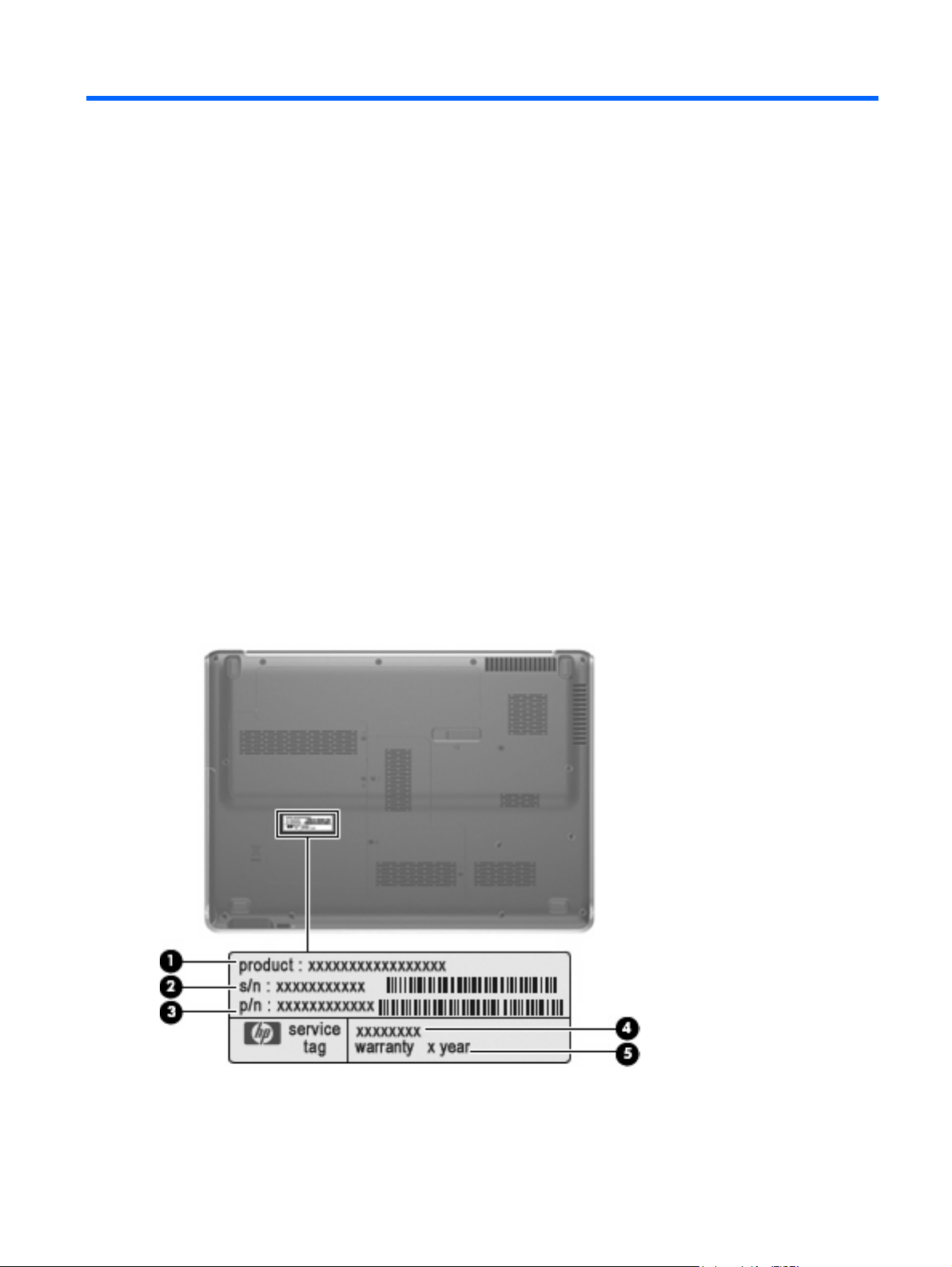
Service tag
The service tag, affixed to the bottom of the computer, provides information that may be needed when
troubleshooting system problems. The service tag provides the following information:
(1) Product name: This is the product name affixed to the front of the computer.
(2) Serial number (s/n): This is an alphanumeric identifier that is unique to each product.
(3) Part number/Product number (p/n): This number provides specific information about the product's
hardware components. The part number helps a service technician to determine what components and
parts are needed.
(4) Model description: This is the number needed to locate documents, drivers, and support for the
computer.
(5) Warranty period: Describes the duration of the warranty period for the computer.
Service tag 17
Page 26

Computer major components
Item Description Spare part number
(1) 15.4-inch display assemblies (include wireless antenna transceivers and cables)
WSXGA+ BrightView display assembly with webcam and 2 microphones 484368-001
WXGA AntiGlare display assembly with webcam and 2 microphones 484371-001
WSXGA+ AntiGlare display assembly with webcam and 2 microphones 484372-001
18 Chapter 3 Illustrated parts catalog
Page 27

Item Description Spare part number
WXGA Brightview display assembly with webcam and 2 microphones 484367-001
NOTE: See Display assembly components on page 27 for more information on display assembly spare part
numbers.
(2)
(3) Power button board (includes cable) 486796-001
(4) Keyboards (include keyboard cable)
Brazil 488590-201
Canada 488590-121
The Czech Republic 488590-221
Denmark, Norway, and Sweden 488590-DH1
France 488590-051
Germany 488590-041
Greece 488590-151
Hungary 488590-211
Israel 488590-BB1
Italy 488590-061
Japan 488590-291
Latin America 488590-161
Switch cover (includes LED board and cable) 488316-001
Belgium 488590-A41
The Netherlands and Europe 488590-B31
Portugal 488590-131
Russia 488590-251
Saudi Arabia 488590-171
South Korea 488590-AD1
Spain 488590-071
Switzerland 488590-111
Taiwan 488590-AB1
Thailand 488590-281
Turkey 488590-141
The United Kingdom 488590-031
The United States 488590-001
(5) Speaker assembly 486801-001
(6) Bluetooth® modules (do not include a Bluetooth module cable)
For use only with computer models equipped with Intel processors 483113-001
For use only with computer models equipped with AMD processors 412766-002
Computer major components 19
Page 28

Item Description Spare part number
(7) Bluetooth module cable 489822-001
Cable Kit, includes:
NOTE: See
(8a) Power connector cable
(8b) Modem module cable
(8c) TV tuner module antenna cable
(9a) ExpressCard slot bezel
(9b) Mini Card module compartment cover
(9c) Memory module compartment cover
(9d) Hard drive bay cover
(10) Top covers (include TouchPad and TouchPad buttons):
For use only with computer models not equipped with a fingerprint reader 486526-001
(11) Modem modules:
Plastics Kit, includes:
NOTE: See
For use only with computer models equipped with a fingerprint reader 486527-001
NOTE: The modem module spare part kits do not include a modem module cable. The modem module cable is
included in the Cable Kit, spare part number 501891-001.
Cable Kit on page 31 for more Cable Kit spare part information.
Plastics Kit on page 30 for more Cable Kit spare part information.
501891-001
486793-001
For use only in Australia and New Zealand 461749-011
(12) System boards (include replacement thermal material):
For use only with computer models equipped with AMD processors:
For use only with computer models equipped with Intel processors:
(13) Audio/infrared board (includes cable) 486797-001
(14) USB board (includes cable) 486798-001
(15) Processors (include replacement thermal material):
AMD processors:
For use in all countries and regions except Australia and New Zealand 461749-001
With RX781 Northbridge and ATI-M82-S discrete graphics subsystem memory
●
With RS780 Northbridge and ATI-M UMA graphics subsystem memory
●
With PM45 Northbridge and nVidia NB9P-GS discrete graphics subsystem
●
memory and 512-GB of graphics subsystem memory
With PM45 Northbridge and nVidia NB9M-GE discrete graphics subsystem
●
memory and 256-GB of graphics subsystem memory
With GM45 Northbridge and UMA graphics subsystem memory
●
With ICH9M Northbridge and UMA graphics subsystem memory
●
482324-001
482325-001
482870-001
482867-001
482869-001
482868-001
20 Chapter 3 Illustrated parts catalog
Page 29

Item Description Spare part number
Intel processors:
(16) Fan/heat sink assemblies (include replacement thermal material):
For use only with computer models equipped with AMD processors and graphics
Turion Ultra Dual-Core 35W ZM-86 2.40-GHz processor with 2-MB L2 cache
●
Turion Ultra Dual-Core 35W ZM-82 2.20-GHz, processor with 2-MB L2 cache
●
Turion Ultra Dual-Core 35W ZM-80 2.10-GHz, processor with 2-MB L2 cache
●
Turion Dual-Core 35W RM-70 2.00-GHz with 1-MB L2 cache
●
Athlon X2 Dual-Core 35W QL-60 1.90-GHz with 1-MB L2 cache
●
Intel Core2 Duo T9600 2.80-GHz processor with 6-MB L2 cache and 1066-MHz
●
FSB
Intel Core2 Duo T9400 2.53-GHz processor with 6-MB L2 cache and 1066-MHz
●
FSB
Intel Core Duo T8600 2.40-GHz processor with 3-MB L2 cache and 1066-MHz
●
FSB
Intel Core Duo T8400 2.26-GHz processor with 3-MB L2 cache and 1066-MHz
●
FSB
For use only with computer models equipped with AMD processors and graphics
subsystems with discrete memory
subsystems with UMA memory
484260-001
484261-001
484262-001
484263-001
484264-001
483859-001
483860-001
483861-001
486523-001
493001-001
491572-001
For use only with computer models equipped with Intel processors and graphics
subsystems with discrete memory
For use only with computer models equipped with Intel processors and graphics
subsystems with UMA memory
(17) Base enclosures (include rubber feet)
For use only with computer models equipped with a 1394 port and modem module, but
For use only with computer models equipped with a 1394 port and TV tuner module,
For use only with computer models equipped with a 1394 port, but not a modem module
For use only with computer models equipped with a modem module and a TV tuner
For use only with computer models equipped with a TV tuner module, but not a 1394
For use only with computer models equipped with a modem module, but not a 1394
For use only with computer models not equipped with a 1394 port, modem module, or
For use only with computer models equipped with a 1394 port, modem module, and
TV tuner module
not a TV tuner module
but not a modem module
or a TV tuner module
module, but not a 1394 port
port or modem module
port or TV tuner module
TV tuner module
486799-001
492314-001
486783-001
486784-001
486785-001
486786-001
486787-001
486788-001
486789-001
486790-001
Rubber Feet Kit (not illustrated, includes 4 base enclosure rubber feet) 486794-001
Computer major components 21
Page 30

Item Description Spare part number
(18) Batteries:
6-cell, 55-Wh, 2.55-Ah Li-ion battery for use with all computer models 484171-001
6-cell, 47-Wh, 2.55-Ah Li-ion battery for use only with computer models equipped with
6-cell, 47-Wh, 2.55-Ah Li-ion battery for use only with computer models equipped with
(19) Optical drives (include bezel and bracket):
Blu-ray Disc ROM Drive with SuperMulti DVD±R/RW Double-Layer, LightScribe, and
DVD±RW and CD-RW SuperMulti Double-Layer Combo Drive with LightScribe and
DVD±RW and CD-RW SuperMulti Double-Layer Combo Drive with LightScribe and
DVD±RW and CD-RW SuperMulti Double-Layer Combo Drive with LightScribe and
DVD±RW and CD-RW SuperMulti Double-Layer Combo Drive with bronze bezel 483863-002
DVD±RW and CD-RW SuperMulti Double-Layer Combo Drive with silver bezel 483863-001
12-cell, 95-Wh, 2.55-Ah Li-ion battery for use with all computer models 484172-001
484170-002
AMD processors
484170-001
Intel processors
Blu-ray Disc ROM Drive with SuperMulti DVD±R/RW Double-Layer, LightScribe, and
bronze bezel
silver bezel
bronze bezel for use only with computer models equipped with AMD processors
bronze bezel for use only with computer models equipped with Intel processors
silver bezel
486525-002
486525-001
483864-003
483864-002
483864-001
(20) RTC battery 491571-001
(21) TV tuner modules:
NOTE: The TV tuner module spare part kits do not include a TV tuner module cable. The TV tuner module cable
is included in the Cable Kit, spare part number 501891-001.
DVB-T/ANG TV tuner module 482899-002
NTSC/ATSC/ANG TV tuner module 482899-001
TV tuner external antenna cables (not illustrated):
With PAL jack 482900-002
(22) Memory modules (667-MHz, PC2-5300, 1-DIMM):
1024-MB memory module for use only with computer models equipped with AMD
2048-MB memory module for use only with computer models equipped with Intel
1024-MB memory module for use only with computer models equipped with Intel
DVB-T TV tuner module 482899-003
With F-PAL jack 482900-001
2048-MB memory module for use only with computer models equipped with AMD
processors
processors
processors
processors
484268-002
484267-002
484268-001
484267-001
22 Chapter 3 Illustrated parts catalog
Page 31

Item Description Spare part number
512-MB memory module for use only with computer models equipped with Intel
processors
(23) WLAN modules:
WLAN modules for use only with computer models equipped with AMD processors:
Atheros AR9280 802.11a/b/g/n WLAN module for use in Antigua and Barbuda,
●
Barbados, Belize, Canada, the Cayman Islands, Guam, Puerto Rico,
Trinidad and Tobago, the U.S. Virgin Islands, and the United States
Atheros AR9280 802.11a/b/g/n WLAN module for use in Afghanistan, Albania,
●
Algeria, Andorra, Angola, Antigua and Barbuda, Argentina, Armenia, Aruba,
Australia, Austria, Azerbaijan, the Bahamas, Bahrain, Bangladesh, Barbados,
Belarus, Belgium, Belize, Benin, Bermuda, Bhutan, Bolivia,
Bosnia and Herzegovina, Botswana, Brazil, the British Virgin Islands, Brunei,
Bulgaria, Burkina Faso, Burundi, Cameroon, Cape Verde,
the Central African Republic, Chad, Chile, the People's Republic of China,
Colombia, Comoros, the Congo, Costa Rica, Croatia, Cyprus,
the Czech Republic, Denmark, Djibouti, Dominica, the Dominican Republic,
East Timor, Ecuador, Egypt, El Salvador, Equitorial Guinea, Eritrea, Estonia,
Ethiopia, Fiji, Finland, France, French Guiana, Gabon, Gambia, Georgia,
Germany, Ghana, Gibraltar, Greece, Grenada, Guadeloupe, Guatemala, Guinea,
Guinea-Bissau, Guyana, Haiti, Honduras, Hong Kong, Hungary, Iceland, India,
Ireland, Israel, Italy, the Ivory Coast, Jamaica, Jordan, Kazakhstan, Kenya,
Kiribati, Kyrgyzstan, Laos, Latvia, Lebanon, Lesotho, Liberia, Liechtenstein,
Lithuania, Luxembourg, Macedonia, Madagascar, Malawi, Malaysia,
the Maldives, Mali, Malta, the Marshall Islands, Martinique, Mauritania, Mauritius,
Mexico, Micronesia, Monaco, Mongolia, Montenegro, Morocco, Mozambique,
Namibia, Nauru, Nepal, the Nether Antilles, the Netherlands, New Zealand,
Nicaragua, Niger, Nigeria, Norway, Oman, Pakistan, Palau, Panama,
Papua New Guinea, Paraguay, Peru, the Philippines, Poland, Portugal,
the Republic of Moldova, Romania, Russia, Rwanda, Samoa, San Marino,
Sao Tome and Principe, Saudi Arabia, Senegal, Serbia, the Seychelles,
Sierra Leone, Singapore, Slovakia, Slovenia, the Solomon Islands, Somalia,
South Africa, South Korea, Spain, Sri Lanka, St. Kitts and Nevis, St. Lucia,
St. Vincent and the Grenadines, Suriname, Swaziland, Sweden, Switzerland,
Taiwan, Tajikistan, Tanzania, Togo, Tonga, Trinidad and Tobago, Tunisia, Turkey,
Turkmenistan, Tuvalu, Uganda, Ukraine, the United Arab Emirates,
the United Kingdom, Uruguay, Uzbekistan, Vanuatu, Venezuela, Vietnam,
Yemen, Zaire, Zambia, and Zimbabwe
484266-001
482260-001
482260-002
Broadcom 4321 802.11a/b/g/n WLAN module for use in Antigua and Barbuda,
●
Barbados, Belize, Canada, the Cayman Islands, Guam, Puerto Rico,
Trinidad and Tobago, the U.S. Virgin Islands, and the United States
Broadcom 4321 802.11a/b/g/n WLAN module for use in Afghanistan, Albania,
●
Algeria, Andorra, Angola, Antigua and Barbuda, Argentina, Armenia, Aruba,
Australia, Austria, Azerbaijan, the Bahamas, Bahrain, Bangladesh, Barbados,
Belarus, Belgium, Belize, Benin, Bermuda, Bhutan, Bolivia,
Bosnia and Herzegovina, Botswana, Brazil, the British Virgin Islands, Brunei,
Bulgaria, Burkina Faso, Burundi, Cameroon, Cape Verde,
the Central African Republic, Chad, Chile, the People's Republic of China,
Colombia, Comoros, the Congo, Costa Rica, Croatia, Cyprus,
the Czech Republic, Denmark, Djibouti, Dominica, the Dominican Republic,
East Timor, Ecuador, Egypt, El Salvador, Equitorial Guinea, Eritrea, Estonia,
Ethiopia, Fiji, Finland, France, French Guiana, Gabon, Gambia, Georgia,
Germany, Ghana, Gibraltar, Greece, Grenada, Guadeloupe, Guatemala, Guinea,
Guinea-Bissau, Guyana, Haiti, Honduras, Hong Kong, Hungary, Iceland, India,
Ireland, Israel, Italy, the Ivory Coast, Jamaica, Jordan, Kazakhstan, Kenya,
Kiribati, Kyrgyzstan, Laos, Latvia, Lebanon, Lesotho, Liberia, Liechtenstein,
Lithuania, Luxembourg, Macedonia, Madagascar, Malawi, Malaysia,
the Maldives, Mali, Malta, the Marshall Islands, Martinique, Mauritania, Mauritius,
Mexico, Micronesia, Monaco, Mongolia, Montenegro, Morocco, Mozambique,
453730-001
453730-002
Computer major components 23
Page 32

Item Description Spare part number
Namibia, Nauru, Nepal, the Nether Antilles, the Netherlands, New Zealand,
Nicaragua, Niger, Nigeria, Norway, Oman, Pakistan, Palau, Panama,
Papua New Guinea, Paraguay, Peru, the Philippines, Poland, Portugal,
the Republic of Moldova, Romania, Russia, Rwanda, Samoa, San Marino,
Sao Tome and Principe, Saudi Arabia, Senegal, Serbia, the Seychelles,
Sierra Leone, Singapore, Slovakia, Slovenia, the Solomon Islands, Somalia,
South Africa, South Korea, Spain, Sri Lanka, St. Kitts and Nevis, St. Lucia,
St. Vincent and the Grenadines, Suriname, Swaziland, Sweden, Switzerland,
Taiwan, Tajikistan, Tanzania, Togo, Tonga, Trinidad and Tobago, Tunisia, Turkey,
Turkmenistan, Tuvalu, Uganda, Ukraine, the United Arab Emirates,
the United Kingdom, Uruguay, Uzbekistan, Vanuatu, Venezuela, Vietnam,
Yemen, Zaire, Zambia, and Zimbabwe
Atheros AR2425 802.11b/g for use in Antigua and Barbuda, Barbados, Belize,
●
Canada, the Cayman Islands, Guam, Puerto Rico, Trinidad and Tobago,
the U.S. Virgin Islands, and the United States
Atheros AR2425 802.11b/g for use in Afghanistan, Albania, Algeria, Andorra,
●
Angola, Antigua and Barbuda, Argentina, Armenia, Aruba, Australia, Austria,
Azerbaijan, the Bahamas, Bahrain, Bangladesh, Barbados, Belarus, Belgium,
Belize, Benin, Bermuda, Bhutan, Bolivia, Bosnia and Herzegovina, Botswana,
Brazil, the British Virgin Islands, Brunei, Bulgaria, Burkina Faso, Burundi,
Cameroon, Cape Verde, the Central African Republic, Chad, Chile,
the People's Republic of China, Colombia, Comoros, the Congo, Costa Rica,
Croatia, Cyprus, the Czech Republic, Denmark, Djibouti, Dominica,
the Dominican Republic, East Timor, Ecuador, Egypt, El Salvador,
Equitorial Guinea, Eritrea, Estonia, Ethiopia, Fiji, Finland, France, French Guiana,
Gabon, Gambia, Georgia, Germany, Ghana, Gibraltar, Greece, Grenada,
Guadeloupe, Guatemala, Guinea, Guinea-Bissau, Guyana, Haiti, Honduras,
Hong Kong, Hungary, Iceland, India, Ireland, Israel, Italy, the Ivory Coast,
Jamaica, Jordan, Kazakhstan, Kenya, Kiribati, Kyrgyzstan, Laos, Latvia,
Lebanon, Lesotho, Liberia, Liechtenstein, Lithuania, Luxembourg, Macedonia,
Madagascar, Malawi, Malaysia, the Maldives, Mali, Malta, the Marshall Islands,
Martinique, Mauritania, Mauritius, Mexico, Micronesia, Monaco, Mongolia,
Montenegro, Morocco, Mozambique, Namibia, Nauru, Nepal, the Nether Antilles,
the Netherlands, New Zealand, Nicaragua, Niger, Nigeria, Norway, Oman,
Pakistan, Palau, Panama, Papua New Guinea, Paraguay, Peru, the Philippines,
Poland, Portugal, the Republic of Moldova, Romania, Russia, Rwanda, Samoa,
San Marino, Sao Tome and Principe, Saudi Arabia, Senegal, Serbia,
the Seychelles, Sierra Leone, Singapore, Slovakia, Slovenia,
the Solomon Islands, Somalia, South Africa, South Korea, Spain, Sri Lanka,
St. Kitts and Nevis, St. Lucia, St. Vincent and the Grenadines, Suriname,
Swaziland, Sweden, Switzerland, Taiwan, Tajikistan, Tanzania, Togo, Tonga,
Trinidad and Tobago, Tunisia, Turkey, Turkmenistan, Tuvalu, Uganda, Ukraine,
the United Arab Emirates, the United Kingdom, Uruguay, Uzbekistan, Vanuatu,
Venezuela, Vietnam, Yemen, Zaire, Zambia, and Zimbabwe
459339-001
459339-002
WLAN modules for use only with computer models equipped with Intel processors:
Intel Wi-Fi Link 5100 802.11a/b/g WLAN module for use in all countries and
●
regions
Intel Wi-Fi Link 5100 802.11a/b/g/n WLAN module for use in all countries and
●
regions
Broadcom 4322 802.11a/b/g/n WLAN module for use in Antigua and Barbuda,
●
Barbados, Belize, Canada, the Cayman Islands, Guam, Puerto Rico,
Trinidad and Tobago, the U.S. Virgin Islands, and the United States
Broadcom 4322 802.11a/b/g/n WLAN module for use in Afghanistan, Albania,
●
Algeria, Andorra, Angola, Antigua and Barbuda, Argentina, Armenia, Aruba,
Australia, Austria, Azerbaijan, the Bahamas, Bahrain, Bangladesh, Barbados,
Belarus, Belgium, Belize, Benin, Bermuda, Bhutan, Bolivia,
Bosnia and Herzegovina, Botswana, Brazil, the British Virgin Islands, Brunei,
24 Chapter 3 Illustrated parts catalog
482957-001
480985-001
487330-001
487330-002
Page 33

Item Description Spare part number
Bulgaria, Burkina Faso, Burundi, Cameroon, Cape Verde,
the Central African Republic, Chad, Chile, the People's Republic of China,
Colombia, Comoros, the Congo, Costa Rica, Croatia, Cyprus,
the Czech Republic, Denmark, Djibouti, Dominica, the Dominican Republic,
East Timor, Ecuador, Egypt, El Salvador, Equitorial Guinea, Eritrea, Estonia,
Ethiopia, Fiji, Finland, France, French Guiana, Gabon, Gambia, Georgia,
Germany, Ghana, Gibraltar, Greece, Grenada, Guadeloupe, Guatemala, Guinea,
Guinea-Bissau, Guyana, Haiti, Honduras, Hong Kong, Hungary, Iceland, India,
Ireland, Israel, Italy, the Ivory Coast, Jamaica, Jordan, Kazakhstan, Kenya,
Kiribati, Kyrgyzstan, Laos, Latvia, Lebanon, Lesotho, Liberia, Liechtenstein,
Lithuania, Luxembourg, Macedonia, Madagascar, Malawi, Malaysia,
the Maldives, Mali, Malta, the Marshall Islands, Martinique, Mauritania, Mauritius,
Mexico, Micronesia, Monaco, Mongolia, Montenegro, Morocco, Mozambique,
Namibia, Nauru, Nepal, the Nether Antilles, the Netherlands, New Zealand,
Nicaragua, Niger, Nigeria, Norway, Oman, Pakistan, Palau, Panama,
Papua New Guinea, Paraguay, Peru, the Philippines, Poland, Portugal,
the Republic of Moldova, Romania, Russia, Rwanda, Samoa, San Marino,
Sao Tome and Principe, Saudi Arabia, Senegal, Serbia, the Seychelles,
Sierra Leone, Singapore, Slovakia, Slovenia, the Solomon Islands, Somalia,
South Africa, South Korea, Spain, Sri Lanka, St. Kitts and Nevis, St. Lucia,
St. Vincent and the Grenadines, Suriname, Swaziland, Sweden, Switzerland,
Taiwan, Tajikistan, Tanzania, Togo, Tonga, Trinidad and Tobago, Tunisia, Turkey,
Turkmenistan, Tuvalu, Uganda, Ukraine, the United Arab Emirates,
the United Kingdom, Uruguay, Uzbekistan, Vanuatu, Venezuela, Vietnam,
Yemen, Zaire, Zambia, and Zimbabwe
Broadcom BCM4312 802.11b/g WLAN module for use in Antigua and Barbuda,
●
Barbados, Belize, Canada, the Cayman Islands, Guam, Puerto Rico,
Trinidad and Tobago, the U.S. Virgin Islands, and the United States
Broadcom BCM4312 802.11b/g WLAN module for use in Afghanistan, Albania,
●
Algeria, Andorra, Angola, Antigua and Barbuda, Argentina, Armenia, Aruba,
Australia, Austria, Azerbaijan, the Bahamas, Bahrain, Bangladesh, Barbados,
Belarus, Belgium, Belize, Benin, Bermuda, Bhutan, Bolivia,
Bosnia and Herzegovina, Botswana, Brazil, the British Virgin Islands, Brunei,
Bulgaria, Burkina Faso, Burundi, Cameroon, Cape Verde,
the Central African Republic, Chad, Chile, the People's Republic of China,
Colombia, Comoros, the Congo, Costa Rica, Croatia, Cyprus,
the Czech Republic, Denmark, Djibouti, Dominica, the Dominican Republic,
East Timor, Ecuador, Egypt, El Salvador, Equitorial Guinea, Eritrea, Estonia,
Ethiopia, Fiji, Finland, France, French Guiana, Gabon, Gambia, Georgia,
Germany, Ghana, Gibraltar, Greece, Grenada, Guadeloupe, Guatemala, Guinea,
Guinea-Bissau, Guyana, Haiti, Honduras, Hong Kong, Hungary, Iceland, India,
Ireland, Israel, Italy, the Ivory Coast, Jamaica, Jordan, Kazakhstan, Kenya,
Kiribati, Kyrgyzstan, Laos, Latvia, Lebanon, Lesotho, Liberia, Liechtenstein,
Lithuania, Luxembourg, Macedonia, Madagascar, Malawi, Malaysia,
the Maldives, Mali, Malta, the Marshall Islands, Martinique, Mauritania, Mauritius,
Mexico, Micronesia, Monaco, Mongolia, Montenegro, Morocco, Mozambique,
Namibia, Nauru, Nepal, the Nether Antilles, the Netherlands, New Zealand,
Nicaragua, Niger, Nigeria, Norway, Oman, Pakistan, Palau, Panama,
Papua New Guinea, Paraguay, Peru, the Philippines, Poland, Portugal,
the Republic of Moldova, Romania, Russia, Rwanda, Samoa, San Marino,
Sao Tome and Principe, Saudi Arabia, Senegal, Serbia, the Seychelles,
Sierra Leone, Singapore, Slovakia, Slovenia, the Solomon Islands, Somalia,
South Africa, South Korea, Spain, Sri Lanka, St. Kitts and Nevis, St. Lucia,
St. Vincent and the Grenadines, Suriname, Swaziland, Sweden, Switzerland,
Taiwan, Tajikistan, Tanzania, Togo, Tonga, Trinidad and Tobago, Tunisia, Turkey,
Turkmenistan, Tuvalu, Uganda, Ukraine, the United Arab Emirates,
the United Kingdom, Uruguay, Uzbekistan, Vanuatu, Venezuela, Vietnam,
Yemen, Zaire, Zambia, and Zimbabwe
459263-001
459263-002
(24) Hard drives (include left and right bracket rails, connector cable, Mylar cover with tab, and 4 rubber isolators):
Computer major components 25
Page 34

Item Description Spare part number
Hard drives for use only with computer models equipped with AMD processors:
Hard drives for use only with computer models equipped with Intel processors:
Hard Drive Hardware Kit (not illustrated, includes left and right bracket rails, connector
320-GB, 5400-rpm
●
250-GB, 5400-rpm
●
160-GB, 5400-rpm
●
120-GB, 5400-rpm
●
320-GB, 5400-rpm
●
250-GB, 5400-rpm
●
160-GB, 7200-rpm
●
160-GB, 5400-rpm
●
120-GB, 5400-rpm
●
cable, Mylar cover with tab, and 4 rubber isolators)
462355-002
489819-002
489818-002
489817-002
462355-001 and
489821-001
489819-001
489820-001
489818-001
489817-001
483862-001
26 Chapter 3 Illustrated parts catalog
Page 35

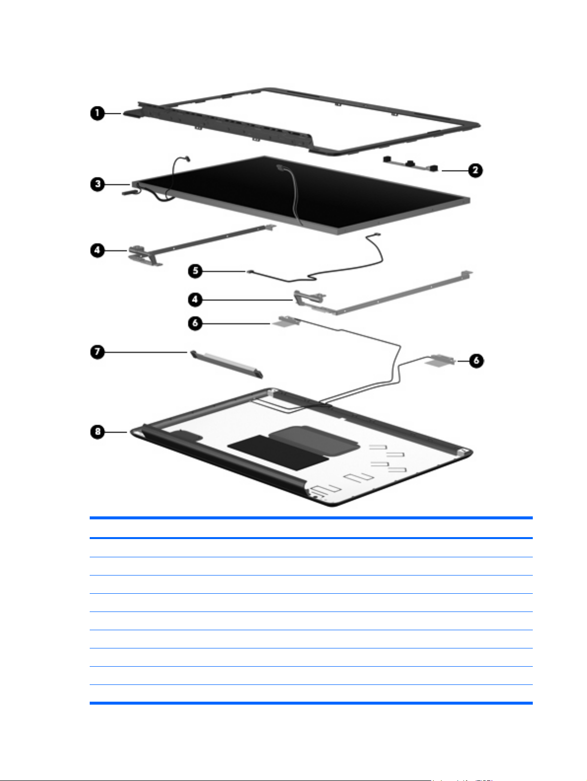
Display assembly components
The HP Pavilion dv5 Entertainment PC offers 2 types of display assemblies. Component spare parts
are listed in this section for AntiGlare display assemblies and BrightView display assemblies.
AntiGlare display assembly spare parts
Item Description Spare part number
(1) Display enclosure (includes wireless antenna transceivers and cables): 485339-001
(2) Display inverter cover 486792-001
(3) Display inverter 488317-001
(4) Webcam/microphone module 485345-001
(5) Display Hinge Kit (includes left and right hinges) 485340-001
Display Rubber Kit (not illustrated, includes display bezel rubber screw covers) 486537-001
Display Screw Kit (not illustrated) 485343-001
Display assembly components 27
Page 36
BrightView display assembly spare parts
Item Description Spare part number
(1) Display bezel (includes logo and display lid switch actuator magnet) 480444-001
(2) Webcam/microphone module 480446-001
(3) BrightView display panels (include display panel cable):
For use only with computer models equipped with WXGA display panels 480440-001
(4) Display Hinge Kit (includes left and right hinges) 486534-001
(5) Display Cable Kits (include display panel cable, not illustrated, and microphone receiver and cable)
For use only with computer models equipped with WXGA display panels 493020-001
For use only with computer models equipped with WSXGA+ display panels 480441-001
For use only with computer models equipped with WSXGA+ display panels 486536-001
28 Chapter 3 Illustrated parts catalog
Page 37

Item Description Spare part number
(6) Wireless antenna transceivers and cables:
For use with computer models equipped with 802.11a/b/g and 802.11b/g WLAN
(7) Display inverter 488317-001
(8) Display enclosures (include wireless antenna transceivers and cables and logo LED board and cable):
For use with computer models equipped with 802.11a/b/g and 802.11b/g WLAN
Display Rubber Kit (not illustrated, includes display bezel rubber screw covers) 480442-001
Display Screw Kit (not illustrated) 480443-001
For use with computer models equipped with 802.11a/b/g/n WLAN modules (includes
3 wireless antenna transceivers and cables)
modules (includes 2 wireless antenna transceivers and cables)
For use with computer models equipped with 802.11a/b/g/n WLAN modules (includes
3 wireless antenna transceivers and cables)
modules (includes 2 wireless antenna transceivers and cables)
489804-001
487748-001
480445-001
488884-001
Display assembly components 29
Page 38
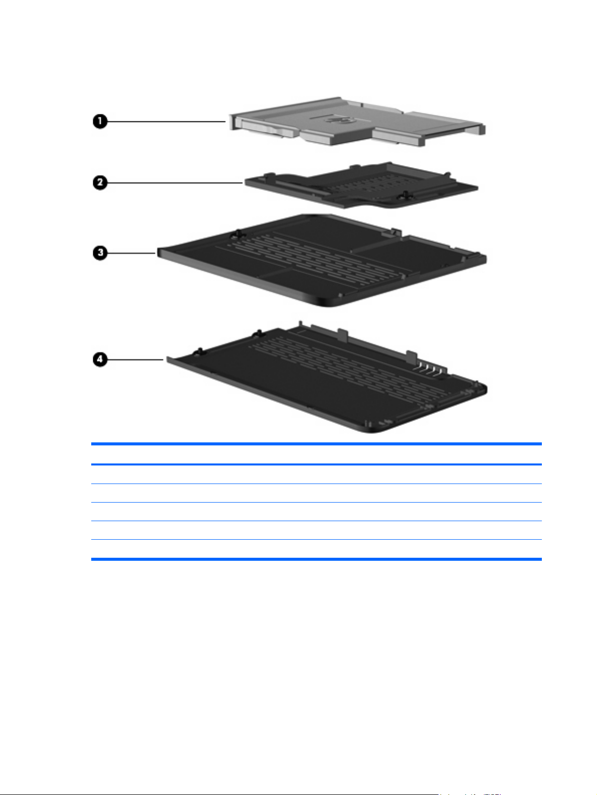
Plastics Kit
Item Description Spare part number
Plastics Kit 486793-001
(1) ExpressCard slot bezel
(2) Mini Card module compartment cover (includes 1 captive screw, secured by a C-clip)
(3) Memory module compartment cover (includes 1 captive screw, secured by a C-clip)
(4) Hard drive bay cover (includes 2 captive screws, secured by C-clips)
30 Chapter 3 Illustrated parts catalog
Page 39

Cable Kit
Item Description Spare part number
Cable Kit 501891-001
(1) Bluetooth module cable
(2) Power connector cable
(3) Modem module cable (includes RJ-11 jack)
(4) TV tuner module cable
Cable Kit 31
Page 40

Mass storage devices
Item Description Spare part number
(1) Hard drives (include left and right bracket rails, connector cable, Mylar cover with tab, and 4 rubber isolators):
For use only with computer models equipped with AMD processors:
For use only with computer models equipped with Intel processors:
Hard Drive Hardware Kit (not illustrated, includes left and right bracket rails,
(2) Optical drives (include bezel and bracket)
320-GB, 5400-rpm
●
250-GB, 5400-rpm
●
160-GB, 5400-rpm
●
120-GB, 5400-rpm
●
320-GB, 5400-rpm
●
250-GB, 5400-rpm
●
160-GB, 7200-rpm
●
160-GB, 5400-rpm
●
120-GB, 5400-rpm
●
connector cable, Mylar cover with tab, and 4 rubber isolators)
462355-002
489819-002
489818-002
489817-002
462355-001 and
489821-001
489819-001
489820-001
489818-001
489817-001
483862-001
Blu-ray Disc ROM Drive with SuperMulti DVD±R/RW Double-Layer, LightScribe, and
bronze bezel
32 Chapter 3 Illustrated parts catalog
486525-002
Page 41

Item Description Spare part number
Blu-ray Disc ROM Drive with SuperMulti DVD±R/RW Double-Layer, LightScribe, and
silver bezel
DVD±RW and CD-RW SuperMulti Double-Layer Combo Drive with LightScribe and
bronze bezel for use only with computer models equipped with AMD processors
DVD±RW and CD-RW SuperMulti Double-Layer Combo Drive with LightScribe and
bronze bezel for use only with computer models equipped with Intel processors
DVD±RW and CD-RW SuperMulti Double-Layer Combo Drive with LightScribe and
silver bezel
DVD±RW and CD-RW SuperMulti Double-Layer Combo Drive with bronze bezel 483863-002
DVD±RW and CD-RW SuperMulti Double-Layer Combo Drive with silver bezel 483863-001
486525-001
483864-003
483864-002
483864-001
Mass storage devices 33
Page 42

Miscellaneous parts
Description Spare part number
AC adapters
90-W AC adapter
65-W AC adapter 463958-001
Carrying cases
HP carrying case
HP slim bag 418163-001
CAT5E cable 454619-001
Wired headset with volume control 371693-003
Optical mouse 436238-001
Wireless laser mouse (includes infrared transceiver) 430958-001
Power cords:
Argentina 490371-D01
Australia and New Zealand 490371-011
Belgium, Europe, Finland, France, Germany, Greece, the Netherlands, Norway, Portugal, Spain,
and Sweden
Brazil 490371-201
Canada, French Canada, Latin America, Thailand, and the United States 490371-001
391173-001 and
463955-001
418162-001
490371-021
Denmark 490371-081
India 490371-D61
Israel 490371-BB1
Italy 490371-061
Japan 490371-291
The People's Republic of China 490371-AA1
South Africa 490371-AR1
South Korea 490371-AD1
Switzerland 490371-111
Taiwan 490371-AB1
The United Kingdom and Hong Kong 490371-031
Remote controls
Full-function remote control
Full-function remote control with teletext 464793-001
465540-001
34 Chapter 3 Illustrated parts catalog
Page 43

Description Spare part number
Thin profile remote control (fits into ExpressCard slot) 465541-001
Screw Kit
Phillips PM3.0×4.0 screw
●
Phillips PM2.5×7.0 screw
●
Phillips PM2.5×6.0 screw
●
Phillips PM2.5×6.0 captive screw
●
Phillips PM2.5×4.0 screw
●
Phillips PM2.0×10.0 captive screw
●
Phillips PM2.0×4.0 screw
●
Sequential part number listing
Spare part
number
371693-003 Wired headset with volume control
391173-001 90-W AC adapter
412766-002 Bluetooth module for use only with computer models equipped with AMD processors (does not include a
Description
Bluetooth module cable)
486795-001 and
493002-001
NOTE: The Bluetooth module cable is available using spare part number 489822-001.
418162-001 HP carrying case
418163-001 HP slim bag carrying case
430958-001 Wireless laser mouse (includes infrared transceiver)
436238-001 Optical mouse
453730-001 Broadcom 4321 802.11a/b/g/n WLAN module for use only with computer models equipped with AMD
processors in Antigua and Barbuda, Barbados, Belize, Canada, the Cayman Islands, Guam, Puerto Rico,
Trinidad and Tobago, the U.S. Virgin Islands, and the United States
453730-002 Broadcom 4321 802.11a/b/g/n WLAN module for use only with computer models equipped with AMD
processors in Afghanistan, Albania, Algeria, Andorra, Angola, Antigua and Barbuda, Argentina, Armenia,
Aruba, Australia, Austria, Azerbaijan, the Bahamas, Bahrain, Bangladesh, Barbados, Belarus, Belgium,
Belize, Benin, Bermuda, Bhutan, Bolivia, Bosnia and Herzegovina, Botswana, Brazil,
the British Virgin Islands, Brunei, Bulgaria, Burkina Faso, Burundi, Cameroon, Cape Verde,
the Central African Republic, Chad, Chile, the People's Republic of China, Colombia, Comoros,
the Congo, Costa Rica, Croatia, Cyprus, the Czech Republic, Denmark, Djibouti, Dominica,
the Dominican Republic, East Timor, Ecuador, Egypt, El Salvador, Equitorial Guinea, Eritrea, Estonia,
Ethiopia, Fiji, Finland, France, French Guiana, Gabon, Gambia, Georgia, Germany, Ghana, Gibraltar,
Greece, Grenada, Guadeloupe, Guatemala, Guinea, Guinea-Bissau, Guyana, Haiti, Honduras,
Hong Kong, Hungary, Iceland, India, Ireland, Israel, Italy, the Ivory Coast, Jamaica, Jordan, Kazakhstan,
Kenya, Kiribati, Kyrgyzstan, Laos, Latvia, Lebanon, Lesotho, Liberia, Liechtenstein, Lithuania,
Luxembourg, Macedonia, Madagascar, Malawi, Malaysia, the Maldives, Mali, Malta, the Marshall Islands,
Martinique, Mauritania, Mauritius, Mexico, Micronesia, Monaco, Mongolia, Montenegro, Morocco,
Mozambique, Namibia, Nauru, Nepal, the Nether Antilles, the Netherlands, New Zealand, Nicaragua,
Niger, Nigeria, Norway, Oman, Pakistan, Palau, Panama, Papua New Guinea, Paraguay, Peru,
the Philippines, Poland, Portugal, the Republic of Moldova, Romania, Russia, Rwanda, Samoa,
San Marino, Sao Tome and Principe, Saudi Arabia, Senegal, Serbia, the Seychelles, Sierra Leone,
Sequential part number listing 35
Page 44

Spare part
number
454619-001 CAT5E cable
459263-001 Broadcom BCM4312 802.11b/g WLAN module for use only with computer models equipped with Intel
459263-002 Broadcom BCM4312 802.11b/g WLAN module for use only with computer models equipped with Intel
Description
Singapore, Slovakia, Slovenia, the Solomon Islands, Somalia, South Africa, South Korea, Spain,
Sri Lanka, St. Kitts and Nevis, St. Lucia, St. Vincent and the Grenadines, Suriname, Swaziland, Sweden,
Switzerland, Taiwan, Tajikistan, Tanzania, Togo, Tonga, Trinidad and Tobago, Tunisia, Turkey,
Turkmenistan, Tuvalu, Uganda, Ukraine, the United Arab Emirates, the United Kingdom, Uruguay,
Uzbekistan, Vanuatu, Venezuela, Vietnam, Yemen, Zaire, Zambia, and Zimbabwe
processors in Antigua and Barbuda, Barbados, Belize, Canada, the Cayman Islands, Guam, Puerto Rico,
Trinidad and Tobago, the U.S. Virgin Islands, and the United States
processors in Afghanistan, Albania, Algeria, Andorra, Angola, Antigua and Barbuda, Argentina, Armenia,
Aruba, Australia, Austria, Azerbaijan, the Bahamas, Bahrain, Bangladesh, Barbados, Belarus, Belgium,
Belize, Benin, Bermuda, Bhutan, Bolivia, Bosnia and Herzegovina, Botswana, Brazil,
the British Virgin Islands, Brunei, Bulgaria, Burkina Faso, Burundi, Cameroon, Cape Verde,
the Central African Republic, Chad, Chile, the People's Republic of China, Colombia, Comoros,
the Congo, Costa Rica, Croatia, Cyprus, the Czech Republic, Denmark, Djibouti, Dominica,
the Dominican Republic, East Timor, Ecuador, Egypt, El Salvador, Equitorial Guinea, Eritrea, Estonia,
Ethiopia, Fiji, Finland, France, French Guiana, Gabon, Gambia, Georgia, Germany, Ghana, Gibraltar,
Greece, Grenada, Guadeloupe, Guatemala, Guinea, Guinea-Bissau, Guyana, Haiti, Honduras,
Hong Kong, Hungary, Iceland, India, Ireland, Israel, Italy, the Ivory Coast, Jamaica, Jordan, Kazakhstan,
Kenya, Kiribati, Kyrgyzstan, Laos, Latvia, Lebanon, Lesotho, Liberia, Liechtenstein, Lithuania,
Luxembourg, Macedonia, Madagascar, Malawi, Malaysia, the Maldives, Mali, Malta, the Marshall Islands,
Martinique, Mauritania, Mauritius, Mexico, Micronesia, Monaco, Mongolia, Montenegro, Morocco,
Mozambique, Namibia, Nauru, Nepal, the Nether Antilles, the Netherlands, New Zealand, Nicaragua,
Niger, Nigeria, Norway, Oman, Pakistan, Palau, Panama, Papua New Guinea, Paraguay, Peru,
the Philippines, Poland, Portugal, the Republic of Moldova, Romania, Russia, Rwanda, Samoa,
San Marino, Sao Tome and Principe, Saudi Arabia, Senegal, Serbia, the Seychelles, Sierra Leone,
Singapore, Slovakia, Slovenia, the Solomon Islands, Somalia, South Africa, South Korea, Spain,
Sri Lanka, St. Kitts and Nevis, St. Lucia, St. Vincent and the Grenadines, Suriname, Swaziland, Sweden,
Switzerland, Taiwan, Tajikistan, Tanzania, Togo, Tonga, Trinidad and Tobago, Tunisia, Turkey,
Turkmenistan, Tuvalu, Uganda, Ukraine, the United Arab Emirates, the United Kingdom, Uruguay,
Uzbekistan, Vanuatu, Venezuela, Vietnam, Yemen, Zaire, Zambia, and Zimbabwe
459339-001 Atheros AR2425 802.11b/g for use only with computer models equipped with AMD processors in
Antigua and Barbuda, Barbados, Belize, Canada, the Cayman Islands, Guam, Puerto Rico,
Trinidad and Tobago, the U.S. Virgin Islands, and the United States
459339-002 Atheros AR2425 802.11b/g for use only with computer models equipped with AMD processors in
Afghanistan, Albania, Algeria, Andorra, Angola, Antigua and Barbuda, Argentina, Armenia, Aruba,
Australia, Austria, Azerbaijan, the Bahamas, Bahrain, Bangladesh, Barbados, Belarus, Belgium, Belize,
Benin, Bermuda, Bhutan, Bolivia, Bosnia and Herzegovina, Botswana, Brazil, the British Virgin Islands,
Brunei, Bulgaria, Burkina Faso, Burundi, Cameroon, Cape Verde, the Central African Republic, Chad,
Chile, the People's Republic of China, Colombia, Comoros, the Congo, Costa Rica, Croatia, Cyprus,
the Czech Republic, Denmark, Djibouti, Dominica, the Dominican Republic, East Timor, Ecuador, Egypt,
El Salvador, Equitorial Guinea, Eritrea, Estonia, Ethiopia, Fiji, Finland, France, French Guiana, Gabon,
Gambia, Georgia, Germany, Ghana, Gibraltar, Greece, Grenada, Guadeloupe, Guatemala, Guinea,
Guinea-Bissau, Guyana, Haiti, Honduras, Hong Kong, Hungary, Iceland, India, Ireland, Israel, Italy,
the Ivory Coast, Jamaica, Jordan, Kazakhstan, Kenya, Kiribati, Kyrgyzstan, Laos, Latvia, Lebanon,
Lesotho, Liberia, Liechtenstein, Lithuania, Luxembourg, Macedonia, Madagascar, Malawi, Malaysia,
the Maldives, Mali, Malta, the Marshall Islands, Martinique, Mauritania, Mauritius, Mexico, Micronesia,
Monaco, Mongolia, Montenegro, Morocco, Mozambique, Namibia, Nauru, Nepal, the Nether Antilles,
the Netherlands, New Zealand, Nicaragua, Niger, Nigeria, Norway, Oman, Pakistan, Palau, Panama,
Papua New Guinea, Paraguay, Peru, the Philippines, Poland, Portugal, the Republic of Moldova,
Romania, Russia, Rwanda, Samoa, San Marino, Sao Tome and Principe, Saudi Arabia, Senegal, Serbia,
the Seychelles, Sierra Leone, Singapore, Slovakia, Slovenia, the Solomon Islands, Somalia, South Africa,
South Korea, Spain, Sri Lanka, St. Kitts and Nevis, St. Lucia, St. Vincent and the Grenadines, Suriname,
Swaziland, Sweden, Switzerland, Taiwan, Tajikistan, Tanzania, Togo, Tonga, Trinidad and Tobago,
Tunisia, Turkey, Turkmenistan, Tuvalu, Uganda, Ukraine, the United Arab Emirates, the United Kingdom,
Uruguay, Uzbekistan, Vanuatu, Venezuela, Vietnam, Yemen, Zaire, Zambia, and Zimbabwe
36 Chapter 3 Illustrated parts catalog
Page 45

Spare part
number
461749-001 Modem module for use in all countries and regions except Australia and New Zealand
461749-011 Modem module for use only in Australia and New Zealand
462355-001 320-GB, 5400-rpm hard drive for use only with computer models equipped with Intel processors (includes
462355-002 320-GB, 5400-rpm hard drive for use only with computer models equipped with AMD processors (includes
463955-001 90-W AC adapter
463958-001 65-W AC adapter
464793-001 Full-function remote control with teletext
465540-001 Full-function remote control
465541-001 Thin profile remote control (fits into ExpressCard slot)
480985-001 Intel Wi-Fi Link 5100 802.11a/b/g/n WLAN module for use only with computer models equipped with Intel
Description
NOTE: The modem module spare part kits do not include a modem module cable. The modem module
cable is included in the Cable Kit, spare part number 501891-001.
NOTE: The modem module spare part kits do not include a modem module cable. The modem module
cable is included in the Cable Kit, spare part number 501891-001.
left and right bracket rails, connector cable, Mylar cover with tab, and 4 rubber isolators)
left and right bracket rails, connector cable, Mylar cover with tab, and 4 rubber isolators)
processors in all countries and regions
482260-001 Atheros AR9280 802.11a/b/g/n WLAN module for use only with computer models equipped with AMD
482260-002 Atheros AR9280 802.11a/b/g/n WLAN module for use only with computer models equipped with AMD
482324-001 System board with RX781 Northbridge and ATI-M82-S discrete graphics subsystem memory for use only
processors in Antigua and Barbuda, Barbados, Belize, Canada, the Cayman Islands, Guam, Puerto Rico,
Trinidad and Tobago, the U.S. Virgin Islands, and the United States
processors in Afghanistan, Albania, Algeria, Andorra, Angola, Antigua and Barbuda, Argentina, Armenia,
Aruba, Australia, Austria, Azerbaijan, the Bahamas, Bahrain, Bangladesh, Barbados, Belarus, Belgium,
Belize, Benin, Bermuda, Bhutan, Bolivia, Bosnia and Herzegovina, Botswana, Brazil,
the British Virgin Islands, Brunei, Bulgaria, Burkina Faso, Burundi, Cameroon, Cape Verde,
the Central African Republic, Chad, Chile, the People's Republic of China, Colombia, Comoros,
the Congo, Costa Rica, Croatia, Cyprus, the Czech Republic, Denmark, Djibouti, Dominica,
the Dominican Republic, East Timor, Ecuador, Egypt, El Salvador, Equitorial Guinea, Eritrea, Estonia,
Ethiopia, Fiji, Finland, France, French Guiana, Gabon, Gambia, Georgia, Germany, Ghana, Gibraltar,
Greece, Grenada, Guadeloupe, Guatemala, Guinea, Guinea-Bissau, Guyana, Haiti, Honduras,
Hong Kong, Hungary, Iceland, India, Ireland, Israel, Italy, the Ivory Coast, Jamaica, Jordan, Kazakhstan,
Kenya, Kiribati, Kyrgyzstan, Laos, Latvia, Lebanon, Lesotho, Liberia, Liechtenstein, Lithuania,
Luxembourg, Macedonia, Madagascar, Malawi, Malaysia, the Maldives, Mali, Malta, the Marshall Islands,
Martinique, Mauritania, Mauritius, Mexico, Micronesia, Monaco, Mongolia, Montenegro, Morocco,
Mozambique, Namibia, Nauru, Nepal, the Nether Antilles, the Netherlands, New Zealand, Nicaragua,
Niger, Nigeria, Norway, Oman, Pakistan, Palau, Panama, Papua New Guinea, Paraguay, Peru,
the Philippines, Poland, Portugal, the Republic of Moldova, Romania, Russia, Rwanda, Samoa,
San Marino, Sao Tome and Principe, Saudi Arabia, Senegal, Serbia, the Seychelles, Sierra Leone,
Singapore, Slovakia, Slovenia, the Solomon Islands, Somalia, South Africa, South Korea, Spain,
Sri Lanka, St. Kitts and Nevis, St. Lucia, St. Vincent and the Grenadines, Suriname, Swaziland, Sweden,
Switzerland, Taiwan, Tajikistan, Tanzania, Togo, Tonga, Trinidad and Tobago, Tunisia, Turkey,
Turkmenistan, Tuvalu, Uganda, Ukraine, the United Arab Emirates, the United Kingdom, Uruguay,
Uzbekistan, Vanuatu, Venezuela, Vietnam, Yemen, Zaire, Zambia, and Zimbabwe
with computer models equipped with AMD processors (includes replacement thermal material)
482325-001 System board with RS780 Northbridge and ATI-M UMA graphics subsystem memory for use only with
computer models equipped with AMD processors (includes replacement thermal material)
Sequential part number listing 37
Page 46

Spare part
number
Description
482867-001 System board with PM45 Northbridge and nVidia NB9M-GE discrete graphics subsystem memory for use
482868-001 System board with ICH9M Northbridge and UMA graphics subsystem memory for use only with computer
482869-001 System board with GM45 Northbridge and UMA graphics subsystem memory for use only with computer
482870-001 System board with PM45 Northbridge and nVidia NB9P-GS discrete graphics subsystem memory for use
482899-001 NTSC/ATSC/ANG TV tuner module
482899-002 DVB-T/ANG TV tuner module
482899-003 DVB-T TV tuner module
482900-001 TV tuner external antenna cable with F-PAL jack
482900-002 TV tuner external antenna cable with PAL jack
only with computer models equipped with Intel processors (includes replacement thermal material)
models equipped with Intel processors (includes replacement thermal material)
models equipped with Intel processors (includes replacement thermal material)
only with computer models equipped with Intel processors (includes replacement thermal material)
NOTE: The TV tuner module spare part kits do not include a TV tuner module cable. The TV tuner
module cable is included in the Cable Kit, spare part number 501891-001.
NOTE: The TV tuner module spare part kits do not include a TV tuner module cable. The TV tuner
module cable is included in the Cable Kit, spare part number 501891-001.
NOTE: The TV tuner module spare part kits do not include a TV tuner module cable. The TV tuner
module cable is included in the Cable Kit, spare part number 501891-001.
482957-001 Intel Wi-Fi Link 5100 802.11a/b/g WLAN module for use only with computer models equipped with Intel
processors in all countries and regions
483113-001 Bluetooth module for use only with computer models equipped with Intel processors (does not include a
483859-001 Intel Core2 Duo T9600 2.80-GHz processor with 6-MB L2 cache and 1066-MHz FSB (includes
483860-001 Intel Core2 Duo T9400 2.53-GHz processor with 6-MB L2 cache and 1066-MHz FSB (includes
483861-001 Intel Core Duo T8600 2.40-GHz processor with 3-MB L2 cache and 1066-MHz FSB (includes replacement
483862-001 Hard Drive Hardware Kit (includes left and right bracket rails, connector cable, Mylar cover with tab, and
483863-001 DVD±RW and CD-RW SuperMulti Double-Layer Combo Drive with bronze bezel (includes bezel and
483863-002 DVD±RW and CD-RW SuperMulti Double-Layer Combo Drive with bronze bezel (includes bezel and
483864-001 DVD±RW and CD-RW SuperMulti Double-Layer Combo Drive with LightScribe and silver bezel (includes
483864-002 DVD±RW and CD-RW SuperMulti Double-Layer Combo Drive with LightScribe and bronze bezel for use
Bluetooth module cable)
NOTE: The Bluetooth module cable is available using spare part number 489822-001.
replacement thermal material)
replacement thermal material)
thermal material)
4 rubber isolators)
bracket)
bracket)
bezel and bracket)
only with computer models equipped with Intel processors (includes bezel and bracket)
483864-003 DVD±RW and CD-RW SuperMulti Double-Layer Combo Drive with LightScribe and bronze bezel for use
only with computer models equipped with AMD processors (includes bezel and bracket)
38 Chapter 3 Illustrated parts catalog
Page 47

Spare part
number
484170-001 6-cell, 55-Wh, 2.55-Ah Li-ion battery for use with all computer models
484170-002 6-cell, 47-Wh, 2.55-Ah Li-ion battery for use only with computer models equipped with AMD processors
484171-001 6-cell, 55-Wh, 2.55-Ah Li-ion battery for use with all computer models
484172-001 12-cell, 95-Wh, 2.55-Ah Li-ion battery for use with all computer models
484260-001 AMD Turion Ultra Dual-Core 35W ZM-86 2.40-GHz processor with 2-MB L2 cache (includes replacement
484261-001 AMD Turion Ultra Dual-Core 35W ZM-82 2.20-GHz, processor with 2-MB L2 cache (includes replacement
484262-001 AMD Turion Ultra Dual-Core 35W ZM-80 2.10-GHz, processor with 2-MB L2 cache (includes replacement
484263-001 AMD Turion Dual-Core 35W RM-70 2.00-GHz with 1-MB L2 cache processor (includes replacement
484264-001 AMD Athlon X2 Dual-Core 35W QL-60 1.90-GHz with 1-MB L2 cache processor (includes replacement
484266-001 512-MB memory module for use only with computer models equipped with Intel processors (667-MHz,
484267-001 1024-MB memory module for use only with computer models equipped with Intel processors (667-MHz,
Description
thermal material)
thermal material)
thermal material)
thermal material)
thermal material)
PC2-5300, 1-DIMM)
PC2-5300, 1-DIMM)
484267-002 1024-MB memory module for use only with computer models equipped with AMD processors (667-MHz,
PC2-5300, 1-DIMM)
484268-001 2048-MB memory module for use only with computer models equipped with Intel processors (667-MHz,
PC2-5300, 1-DIMM)
484268-002 2048-MB memory module for use only with computer models equipped with AMD processors (667-MHz,
PC2-5300, 1-DIMM)
484363-001 15.4-inch WXGA BrightView display panel (includes display panel cable)
484364-001 15.4-inch WSXGA+ BrightView display panel (includes display panel cable)
484367-001 15.4-inch WXGA Brightview display assembly with webcam and 2 microphones
484368-001 15.4-inch WSXGA+ BrightView display assembly with webcam and 2 microphones
484371-001 15.4-inch WXGA AntiGlare display assembly with webcam and 2 microphones
484372-001 15.4-inch WSXGA+ AntiGlare display assembly with webcam and 2 microphones
485339-001 Display enclosure for use only with computer models equipped with AntiGlare display assemblies
(includes wireless antenna transceivers and cables)
485340-001 Display Hinge Kit for use only with computer models equipped with AntiGlare display assemblies (includes
left and right hinges)
485343-001 Display Screw Kit
485344-001 Display Hinge Screw Kit
485345-001 Webcam/microphone module for use only with computer models equipped with AntiGlare display
assemblies (includes double-sided tape)
486523-001 Intel Core Duo T8400 2.26-GHz processor with 3-MB L2 cache and 1066-MHz FSB (includes replacement
thermal material)
Sequential part number listing 39
Page 48

Spare part
number
Description
486525-001 Blu-ray Disc ROM Drive with SuperMulti DVD±R/RW Double-Layer, LightScribe, and bronze bezel
486525-002 Blu-ray Disc ROM Drive with SuperMulti DVD±R/RW Double-Layer, LightScribe, and bronze bezel
486526-001 Top cover for use only with computer models not equipped with a fingerprint reader (includes TouchPad
486527-001 Top cover for use only with computer models equipped with a fingerprint reader (includes TouchPad and
486532-001 Display bezel
486533-001 Display enclosure (includes logo)
486534-001 Display Hinge Kit for use only with computer models equipped with BrightView display assemblies
486536-001 Display panel cable for use with WSXGA+ BrightView display panels
486537-001 Display Rubber Kit (includes display bezel rubber screw covers)
486783-001 Base enclosure for use only with computer models equipped with a 1394 port, modem module, and TV
486784-001 Base enclosure for use only with computer models equipped with a 1394 port and modem module, but
486785-001 Base enclosure for use only with computer models equipped with a 1394 port and TV tuner module, but
(includes bezel and bracket)
(includes bezel and bracket)
and TouchPad buttons)
TouchPad buttons)
(includes left and right display hinges)
tuner module (includes rubber feet)
not a TV tuner module (includes rubber feet)
not a modem module (includes rubber feet)
486786-001 Base enclosure for use only with computer models equipped with a 1394 port, but not a modem module
or a TV tuner module (includes rubber feet)
486787-001 Base enclosure for use only with computer models equipped with a modem module and a TV tuner module,
but not a 1394 port (includes rubber feet)
486788-001 Base enclosure for use only with computer models equipped with a TV tuner module, but not a 1394 port
or modem module (includes rubber feet)
486789-001 Base enclosure for use only with computer models equipped with a modem module, but not a 1394 port
or TV tuner module (includes rubber feet)
486790-001 Base enclosure for use only with computer models not equipped with a 1394 port, modem module, or TV
tuner module (includes rubber feet)
486791-001 Webcam/microphone module for use only with computer models equipped with BrightView display
assemblies (includes double-sided tape)
486792-001 Display inverter cover (for use only with computer models equipped with BrightView display
assemblies)
486793-001 Plastics Kit
NOTE: See
486794-001 Rubber Feet Kit (includes 4 base enclosure rubber feet)
486795-001 Screw Kit
486796-001 Power button board (includes cable)
Plastics Kit on page 30 for more Cable Kit spare part information.
486797-001 Audio/infrared board (includes cable)
40 Chapter 3 Illustrated parts catalog
Page 49

Spare part
number
486798-001 USB board (includes cable)
486799-001 Fan/heat sink assembly for use only with computer models equipped with Intel processors and graphics
486801-001 Speaker assembly
487330-001 Broadcom 4322 802.11a/b/g/n WLAN module for use only with computer models equipped with Intel
487330-002 Broadcom 4322 802.11a/b/g/n WLAN module for use only with computer models equipped with Intel
Description
subsystems with discrete memory (includes replacement thermal material)
processors in Antigua and Barbuda, Barbados, Belize, Canada, the Cayman Islands, Guam, Puerto Rico,
Trinidad and Tobago, the U.S. Virgin Islands, and the United States
processors in Afghanistan, Albania, Algeria, Andorra, Angola, Antigua and Barbuda, Argentina, Armenia,
Aruba, Australia, Austria, Azerbaijan, the Bahamas, Bahrain, Bangladesh, Barbados, Belarus, Belgium,
Belize, Benin, Bermuda, Bhutan, Bolivia, Bosnia and Herzegovina, Botswana, Brazil,
the British Virgin Islands, Brunei, Bulgaria, Burkina Faso, Burundi, Cameroon, Cape Verde,
the Central African Republic, Chad, Chile, the People's Republic of China, Colombia, Comoros,
the Congo, Costa Rica, Croatia, Cyprus, the Czech Republic, Denmark, Djibouti, Dominica,
the Dominican Republic, East Timor, Ecuador, Egypt, El Salvador, Equitorial Guinea, Eritrea, Estonia,
Ethiopia, Fiji, Finland, France, French Guiana, Gabon, Gambia, Georgia, Germany, Ghana, Gibraltar,
Greece, Grenada, Guadeloupe, Guatemala, Guinea, Guinea-Bissau, Guyana, Haiti, Honduras,
Hong Kong, Hungary, Iceland, India, Ireland, Israel, Italy, the Ivory Coast, Jamaica, Jordan, Kazakhstan,
Kenya, Kiribati, Kyrgyzstan, Laos, Latvia, Lebanon, Lesotho, Liberia, Liechtenstein, Lithuania,
Luxembourg, Macedonia, Madagascar, Malawi, Malaysia, the Maldives, Mali, Malta, the Marshall Islands,
Martinique, Mauritania, Mauritius, Mexico, Micronesia, Monaco, Mongolia, Montenegro, Morocco,
Mozambique, Namibia, Nauru, Nepal, the Nether Antilles, the Netherlands, New Zealand, Nicaragua,
Niger, Nigeria, Norway, Oman, Pakistan, Palau, Panama, Papua New Guinea, Paraguay, Peru,
the Philippines, Poland, Portugal, the Republic of Moldova, Romania, Russia, Rwanda, Samoa,
San Marino, Sao Tome and Principe, Saudi Arabia, Senegal, Serbia, the Seychelles, Sierra Leone,
Singapore, Slovakia, Slovenia, the Solomon Islands, Somalia, South Africa, South Korea, Spain,
Sri Lanka, St. Kitts and Nevis, St. Lucia, St. Vincent and the Grenadines, Suriname, Swaziland, Sweden,
Switzerland, Taiwan, Tajikistan, Tanzania, Togo, Tonga, Trinidad and Tobago, Tunisia, Turkey,
Turkmenistan, Tuvalu, Uganda, Ukraine, the United Arab Emirates, the United Kingdom, Uruguay,
Uzbekistan, Vanuatu, Venezuela, Vietnam, Yemen, Zaire, Zambia, and Zimbabwe
488316-001 Switch cover (includes LED board and cable)
488317-001 Display inverter
488590-001 Keyboard for use in the United States
488590-031 Keyboard for use in the United Kingdom
488590-041 Keyboard for use in Germany
488590-051 Keyboard for use in France
488590-061 Keyboard for use in Italy
488590-071 Keyboard for use in Spain
488590-111 Keyboard for use in Switzerland
488590-121 Keyboard for use in French Canada
488590-131 Keyboard for use in Portugal
488590-141 Keyboard for use in Turkey
488590-151 Keyboard for use in Greece
488590-161 Keyboard for use in Latin America
488590-171 Keyboard for use in Saudi Arabia
Sequential part number listing 41
Page 50

Spare part
number
488590-201 Keyboard for use in Brazil
488590-211 Keyboard for use in Hungary
488590-221 Keyboard for use in the Czech Republic
488590-251 Keyboard for use in Russia
488590-281 Keyboard for use in Thailand
488590-291 Keyboard for use in Japan
488590-A41 Keyboard for use in Belgium
488590-AB1 Keyboard for use in Taiwan
488590-AD1 Keyboard for use in South Korea
488590-B31 Keyboard for use in the Netherlands
488590-BB1 Keyboard for use in Israel
488590-DH1 Keyboard for use in Denmark, Norway, and Sweden
489817-001 120-GB, 5400-rpm hard drive for use only with computer models equipped with Intel processors (includes
Description
left and right bracket rails, connector cable, Mylar cover with tab, and 4 rubber isolators)
489817-002 120-GB, 5400-rpm hard drive for use only with computer models equipped with AMD processors (includes
489818-001 160-GB, 5400-rpm hard drive for use only with computer models equipped with Intel processors (includes
489818-002 160-GB, 5400-rpm hard drive for use only with computer models equipped with AMD processors (includes
489819-001 250-GB, 5400-rpm hard drive for use only with computer models equipped with Intel processors (includes
489819-002 250-GB, 5400-rpm hard drive for use only with computer models equipped with AMD processors (includes
489820-001 160-GB, 7200-rpm hard drive for use only with computer models equipped with Intel processors (includes
489821-001 320-GB, 5400-rpm hard drive for use only with computer models equipped with Intel processors (includes
489822-001 Bluetooth module cable
490371-001 Power cord for use in Canada, French Canada, Latin America, Thailand, and the United States
490371-011 Power cord for use in Australia and New Zealand
490371-021 Power cord for use in Belgium, Europe, Finland, France, Germany, Greece, the Netherlands, Norway,
490371-031 Power cord for use in the United Kingdom and Hong Kong
left and right bracket rails, connector cable, Mylar cover with tab, and 4 rubber isolators)
left and right bracket rails, connector cable, Mylar cover with tab, and 4 rubber isolators)
left and right bracket rails, connector cable, Mylar cover with tab, and 4 rubber isolators)
left and right bracket rails, connector cable, Mylar cover with tab, and 4 rubber isolators)
left and right bracket rails, connector cable, Mylar cover with tab, and 4 rubber isolators)
left and right bracket rails, connector cable, Mylar cover with tab, and 4 rubber isolators)
left and right bracket rails, connector cable, Mylar cover with tab, and 4 rubber isolators)
Portugal, Spain, and Sweden
490371-061 Power cord for use in Italy
490371-081 Power cord for use in Denmark
490371-111 Power cord for use in Switzerland
490371-201 Power cord for use in Brazil
42 Chapter 3 Illustrated parts catalog
Page 51

Spare part
number
490371-291 Power cord for use in Japan
490371-AA1 Power cord for use in the People's Republic of China
490371-AB1 Power cord for use in Taiwan
490371-AD1 Power cord for use in South Korea
490371-AR1 Power cord for use in South Africa
490371-BB1 Power cord for use in Israel
490371-D01 Power cord for use in Argentina
490371-D61 Power cord for use in India
491571-001 RTC battery
491572-001 Fan/heat sink assembly for use only with computer models equipped with AMD processors and graphics
Description
subsystems with UMA memory (includes replacement thermal material)
492314-001 Fan/heat sink assembly for use only with computer models equipped with Intel processors and graphics
493001-001 Fan/heat sink assembly for use only with computer models equipped with AMD processors and graphics
493002-001 Screw Kit
493020-001 Display Cable Kit for use with WXGA BrightView display panels
501891-001 Cable Kit
subsystems with UMA memory (includes replacement thermal material)
subsystems with discrete memory (includes replacement thermal material)
NOTE: See
Cable Kit on page 31 for more Cable Kit spare part information.
Sequential part number listing 43
Page 52

4 Removal and replacement procedures
Preliminary replacement requirements
Tools required
You will need the following tools to complete the removal and replacement procedures:
Magnetic screwdriver
●
Phillips P0 and P1 screwdrivers
●
Flat-bladed screwdriver
●
Service considerations
The following sections include some of the considerations that you must keep in mind during
disassembly and assembly procedures.
NOTE: As you remove each subassembly from the computer, place the subassembly (and all
accompanying screws) away from the work area to prevent damage.
Plastic parts
CAUTION: Using excessive force during disassembly and reassembly can damage plastic parts. Use
care when handling the plastic parts. Apply pressure only at the points designated in the maintenance
instructions.
44 Chapter 4 Removal and replacement procedures
Page 53

Cables and connectors
CAUTION: When servicing the computer, be sure that cables are placed in their proper locations
during the reassembly process. Improper cable placement can damage the computer.
Cables must be handled with extreme care to avoid damage. Apply only the tension required to unseat
or seat the cables during removal and insertion. Handle cables by the connector whenever possible. In
all cases, avoid bending, twisting, or tearing cables. Be sure that cables are routed in such a way that
they cannot be caught or snagged by parts being removed or replaced. Handle flex cables with extreme
care; these cables tear easily.
Drive handling
CAUTION: Drives are fragile components that must be handled with care. To prevent damage to the
computer, damage to a drive, or loss of information, observe these precautions:
Before removing or inserting a hard drive, shut down the computer. If you are unsure whether the
computer is off or in Hibernation, turn the computer on, and then shut it down through the operating
system.
Before handling a drive, be sure that you are discharged of static electricity. While handling a drive,
avoid touching the connector.
Before removing a diskette drive or optical drive, be sure that a diskette or disc is not in the drive and
be sure that the optical drive tray is closed.
Handle drives on surfaces covered with at least one inch of shock-proof foam.
Avoid dropping drives from any height onto any surface.
After removing a hard drive, an optical drive, or a diskette drive, place it in a static-proof bag.
Avoid exposing a hard drive to products that have magnetic fields, such as monitors or speakers.
Avoid exposing a drive to temperature extremes or liquids.
If a drive must be mailed, place the drive in a bubble pack mailer or other suitable form of protective
packaging and label the package “FRAGILE.”
Preliminary replacement requirements 45
Page 54

Grounding guidelines
Electrostatic discharge damage
Electronic components are sensitive to electrostatic discharge (ESD). Circuitry design and structure
determine the degree of sensitivity. Networks built into many integrated circuits provide some protection,
but in many cases, ESD contains enough power to alter device parameters or melt silicon junctions.
A discharge of static electricity from a finger or other conductor can destroy static-sensitive devices or
microcircuitry. Even if the spark is neither felt nor heard, damage may have occurred.
An electronic device exposed to ESD may not be affected at all and can work perfectly throughout a
normal cycle. Or the device may function normally for a while, then degrade in the internal layers,
reducing its life expectancy.
CAUTION: To prevent damage to the computer when you are removing or installing internal
components, observe these precautions:
Keep components in their electrostatic-safe containers until you are ready to install them.
Use nonmagnetic tools.
Before touching an electronic component, discharge static electricity by using the guidelines described
in this section.
Avoid touching pins, leads, and circuitry. Handle electronic components as little as possible.
If you remove a component, place it in an electrostatic-safe container.
The following table shows how humidity affects the electrostatic voltage levels generated by different
activities.
CAUTION: A product can be degraded by as little as 700 V.
Typical electrostatic voltage levels
Relative humidity
Event 10% 40% 55%
Walking across carpet 35,000 V 15,000 V 7,500 V
Walking across vinyl floor 12,000 V 5,000 V 3,000 V
Motions of bench worker 6,000 V 800 V 400 V
Removing DIPS from plastic tube 2,000 V 700 V 400 V
Removing DIPS from vinyl tray 11,500 V 4,000 V 2,000 V
Removing DIPS from Styrofoam 14,500 V 5,000 V 3,500 V
Removing bubble pack from PCB 26,500 V 20,000 V 7,000 V
Packing PCBs in foam-lined box 21,000 V 11,000 V 5,000 V
46 Chapter 4 Removal and replacement procedures
Page 55

Packaging and transporting guidelines
Follow these grounding guidelines when packaging and transporting equipment:
To avoid hand contact, transport products in static-safe tubes, bags, or boxes.
●
Protect ESD-sensitive parts and assemblies with conductive or approved containers or packaging.
●
Keep ESD-sensitive parts in their containers until the parts arrive at static-free workstations.
●
Place items on a grounded surface before removing items from their containers.
●
Always be properly grounded when touching a component or assembly.
●
Store reusable ESD-sensitive parts from assemblies in protective packaging or nonconductive
●
foam.
Use transporters and conveyors made of antistatic belts and roller bushings. Be sure that
●
mechanized equipment used for moving materials is wired to ground and that proper materials are
selected to avoid static charging. When grounding is not possible, use an ionizer to dissipate
electric charges.
Workstation guidelines
Follow these grounding workstation guidelines:
Cover the workstation with approved static-shielding material.
●
Use a wrist strap connected to a properly grounded work surface and use properly grounded tools
●
and equipment.
Use conductive field service tools, such as cutters, screwdrivers, and vacuums.
●
When fixtures must directly contact dissipative surfaces, use fixtures made only of static-safe
●
materials.
Keep the work area free of nonconductive materials, such as ordinary plastic assembly aids and
●
Styrofoam.
Handle ESD-sensitive components, parts, and assemblies by the case or PCM laminate. Handle
●
these items only at static-free workstations.
Avoid contact with pins, leads, or circuitry.
●
Turn off power and input signals before inserting or removing connectors or test equipment.
●
Preliminary replacement requirements 47
Page 56

Equipment guidelines
Grounding equipment must include either a wrist strap or a foot strap at a grounded workstation.
When seated, wear a wrist strap connected to a grounded system. Wrist straps are flexible straps
●
with a minimum of one megohm ±10% resistance in the ground cords. To provide proper ground,
wear a strap snugly against the skin at all times. On grounded mats with banana-plug connectors,
use alligator clips to connect a wrist strap.
When standing, use foot straps and a grounded floor mat. Foot straps (heel, toe, or boot straps)
●
can be used at standing workstations and are compatible with most types of shoes or boots. On
conductive floors or dissipative floor mats, use foot straps on both feet with a minimum of one
megohm resistance between the operator and ground. To be effective, the conductive strips must
be worn in contact with the skin.
The following grounding equipment is recommended to prevent electrostatic damage:
Antistatic tape
●
Antistatic smocks, aprons, and sleeve protectors
●
Conductive bins and other assembly or soldering aids
●
Nonconductive foam
●
Conductive tabletop workstations with ground cords of one megohm resistance
●
Static-dissipative tables or floor mats with hard ties to the ground
●
Field service kits
●
Static awareness labels
●
Material-handling packages
●
Nonconductive plastic bags, tubes, or boxes
●
Metal tote boxes
●
Electrostatic voltage levels and protective materials
●
The following table lists the shielding protection provided by antistatic bags and floor mats.
Material Use Voltage protection level
Antistatic plastic Bags 1,500 V
Carbon-loaded plastic Floor mats 7,500 V
Metallized laminate Floor mats 5,000 V
48 Chapter 4 Removal and replacement procedures
Page 57

Unknown user password
If the computer you are servicing has an unknown user password, follow these steps to clear the
password.
NOTE: These steps also clear CMOS.
Before disassembling the computer, follow these steps:
1. Shut down the computer. If you are unsure whether the computer is off or in Hibernation, turn the
computer on, and then shut it down through the operating system.
2. Disconnect all external devices connected to the computer.
3. Disconnect the power from the computer by first unplugging the power cord from the AC outlet and
then unplugging the AC adapter from the computer.
4. Remove the battery (see
5. Remove the RTC battery (see
6. Wait approximately 5 minutes.
7. Replace the RTC battery and reassemble the computer.
8. Connect AC power to the computer. Do not reinsert any batteries at this time.
9. Turn on the computer.
All passwords and all CMOS settings have been cleared.
Battery on page 52).
RTC battery on page 59).
Preliminary replacement requirements 49
Page 58
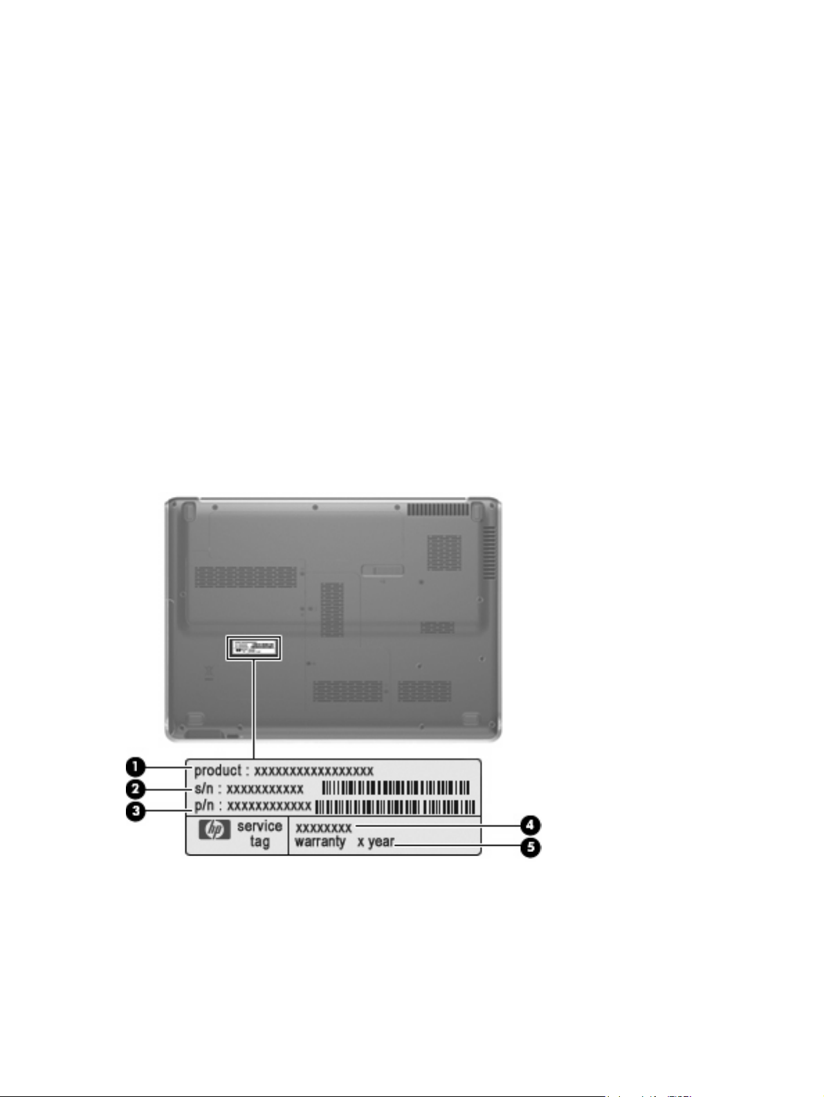
Component replacement procedures
This chapter provides removal and replacement procedures.
There are as many as 91 screws, in 8 different sizes, that must be removed, replaced, or loosened when
servicing the computer. Make special note of each screw size and location during removal and
replacement.
Service tag
The service tag, affixed to the bottom of the computer, provides information that may be needed when
troubleshooting system problems. The service tag provides the following information:
(1) Product name: This is the product name affixed to the front of the computer.
(2) Serial number (s/n): This is an alphanumeric identifier that is unique to each product.
(3) Part number/Product number (p/n): This number provides specific information about the product's
hardware components. The part number helps a service technician to determine what components and
parts are needed.
(4) Model description: This is the number needed to locate documents, drivers, and support for the
computer.
(5) Warranty period: Describes the duration of the warranty period for the computer.
50 Chapter 4 Removal and replacement procedures
Page 59

Computer feet
The computer feet are adhesive-backed rubber pads. The feet are included in the Rubber Feet Kit, spare
part number 486794-001. There are 4 rubber feet that attach to the base enclosure in the locations
illustrated below.
Component replacement procedures 51
Page 60
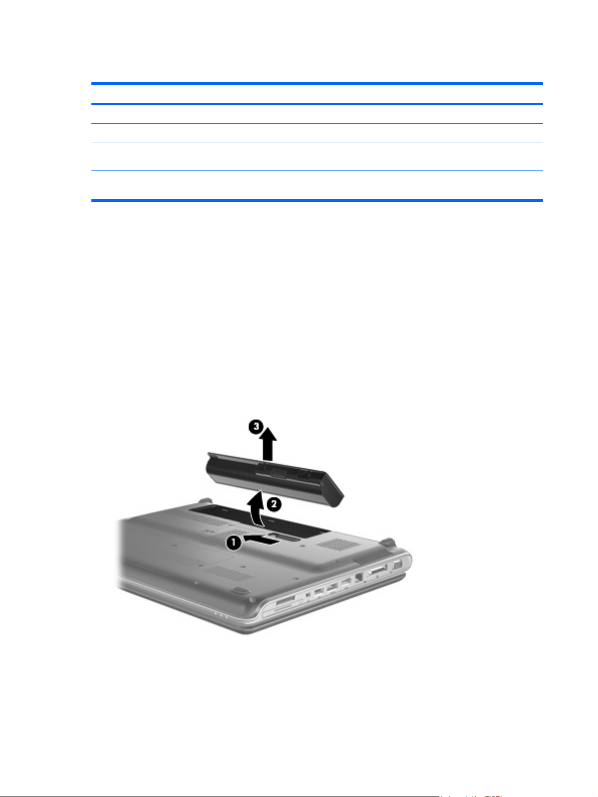
Battery
Description Spare part number
12-cell, 95-Wh, 2.55-Ah Li-ion battery for use with all computer models 484172-001
6-cell, 55-Wh, 2.55-Ah Li-ion battery for use with all computer models 484171-001
6-cell, 47-Wh, 2.55-Ah Li-ion battery for use only with computer models equipped with AMD
processors
6-cell, 47-Wh, 2.55-Ah Li-ion battery for use only with computer models equipped with Intel
processors
484170-002
484170-001
Before disassembling the computer, follow these steps:
1. Shut down the computer. If you are unsure whether the computer is off or in Hibernation, turn the
computer on, and then shut it down through the operating system.
2. Disconnect all external devices connected to the computer.
3. Disconnect the power from the computer by first unplugging the power cord from the AC outlet and
then unplugging the AC adapter from the computer.
Remove the battery:
1. Turn the computer upside down on a flat surface.
2. Slide the battery release latch (1) to release the battery.
3. Pivot the battery (2) upward and remove it (3) from the computer.
To insert the battery, insert the rear edge of the battery into the battery bay and pivot the front edge of
the battery downward until it is seated. The battery release latch automatically locks the battery into
place.
52 Chapter 4 Removal and replacement procedures
Page 61

Webcam/microphone module
NOTE: This section applies only to computer models equipped with BrightView display assemblies.
Display assembly on page 76 for webcam/microphone module removal instructions for computer
See
models equipped with AntiGlare display assemblies.
NOTE: If it has been determined that the webcam/microphone module is the component that must be
replaced to complete the computer repair, the display assembly does not have to be removed. Follow
the procedures in this section to replace the webcam/microphone module. For information on replacing
the display assembly and other display assembly internal components, see
on page 76.
Description Spare part number
Display assembly
Webcam/microphone module for use only with computer models equipped with BrightView display
assemblies (includes double-sided tape)
486791-001
Before removing the webcam/microphone module, follow these steps:
1. Shut down the computer. If you are unsure whether the computer is off or in Hibernation, turn the
computer on, and then shut it down through the operating system.
2. Disconnect all external devices connected to the computer.
3. Disconnect the power from the computer by first unplugging the power cord from the AC outlet and
then unplugging the AC adapter from the computer.
4. Remove the battery (see
Battery on page 52).
Remove the webcam/microphone module:
1. Turn the computer display-side up, with the front toward you.
2. Open the computer as far as possible.
3. Flex the inside edges of the top edge (1) and the left and right upper corners (2) of the display bezel
until the bezel disengages from the display enclosure.
Component replacement procedures 53
Page 62
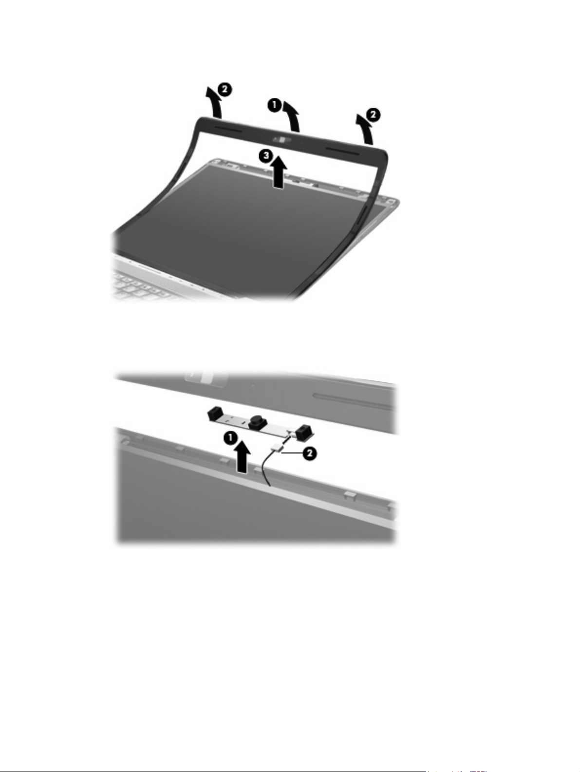
4. Release the display bezel top edge (3) from the display enclosure.
5. Release the webcam/microphone module (1) from the display enclosure as far as the webcam/
microphone module cable allows.
6. Disconnect the webcam/microphone module cable (2) from the webcam/microphone module.
7. Remove the webcam/microphone module.
Reverse this procedure to install the webcam/microphone module.
54 Chapter 4 Removal and replacement procedures
Page 63

Optical drive
NOTE: All optical drive spare part kits include an optical drive bezel and bracket.
Description Spare part number
Blu-ray Disc ROM Drive with SuperMulti DVD±R/RW Double-Layer with LightScribe and bronze
bezel
Blu-ray Disc ROM Drive with SuperMulti DVD±R/RW Double-Layer with LightScribe and silver
bezel
DVD±RW and CD-RW SuperMulti Double-Layer Combo Drive with bronze bezel 483863-002
DVD±RW and CD-RW SuperMulti Double-Layer Combo Drive with LightScribe with bronze bezel
for use only with computer models equipped with AMD processors
DVD±RW and CD-RW SuperMulti Double-Layer Combo Drive with LightScribe with bronze bezel
for use only with computer models equipped with Intel processors
DVD±RW and CD-RW SuperMulti Double-Layer Combo Drive with LightScribe with silver bezel 483864-001
DVD±RW and CD-RW SuperMulti Double-Layer Combo Drive with silver bezel 483863-001
486525-002
486525-001
483864-003
483864-002
Before removing the optical drive, follow these steps:
1. Shut down the computer. If you are unsure whether the computer is off or in Hibernation, turn the
computer on, and then shut it down through the operating system.
2. Disconnect all external devices connected to the computer.
3. Disconnect the power from the computer by first unplugging the power cord from the AC outlet and
then unplugging the AC adapter from the computer.
4. Remove the battery (see
Battery on page 52).
Remove the optical drive:
1. Position the computer with front toward you.
2. Remove the Phillips PM2.5×7.0 screw (1) that secures the optical drive to the computer.
3. Insert a thin tool, such as a paper clip (2), into the disc tray release access hole. (The optical drive
disc tray is partially ejected from the optical drive.)
Component replacement procedures 55
Page 64

4. Use the disc tray frame to slide the optical drive (3) out of the computer.
5. Remove the optical drive.
6. If it is necessary to replace the optical drive bracket, position the optical drive with the optical drive
bracket toward you.
7. Remove the two Phillips PM2.0×4.0 screws (1) that secure the optical drive bracket to the optical
drive.
8. Remove the optical drive bracket (2).
Reverse this procedure to reassemble and install the optical drive.
56 Chapter 4 Removal and replacement procedures
Page 65
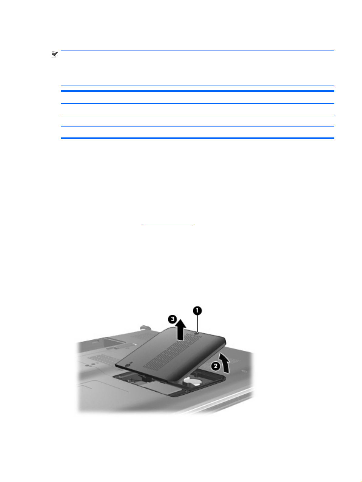
TV tuner module
NOTE: The TV tuner module spare part kits do not include a TV tuner module cable. The TV tuner
module cable is included in the Cable Kit, spare part number 501891-001.
NOTE: The TV tuner external antenna cables are available using spare part numbers 482900-001
(with F-PAL jack) and 482900-002 (with PAL jack).
Description Spare part number
DVB-T TV tuner module 482899-003
DVB-T/ANG TV tuner module 482899-002
NTSC/ATSC/ANG TV tuner module 482899-001
Before removing the TV tuner module, follow these steps:
1. Shut down the computer. If you are unsure whether the computer is off or in Hibernation, turn the
computer on, and then shut it down through the operating system.
2. Disconnect all external devices connected to the computer.
3. Disconnect the power from the computer by first unplugging the power cord from the AC outlet and
then unplugging the AC Adapter from the computer.
4. Remove the battery (see
Battery on page 52).
Remove the TV tuner module:
1. Position the computer with the front toward you
2. Loosen the Phillips PM2.5×6.0 captive screw (1) that secures the Mini Card module compartment
cover to the computer.
3. Lift the right side of the Mini Card module compartment cover (2), swing it to left, and remove the
cover (3). The Mini Card module compartment cover is included in the Plastics Kit, spare part
number 486793-001.
4. Disconnect the TV tuner module antenna cable (1) from the terminal on the TV tuner module.
Component replacement procedures 57
Page 66

5. Remove the two Phillips PM2.0×4.0 screws (2) that secure the TV tuner module to the computer.
(The edge of the module opposite the slot rises away from the computer.)
6. Remove the TV tuner module (3) by pulling the module away from the slot at an angle.
NOTE: The TV tuner module is designed with a notch (4) to prevent incorrect insertion into the
TV tuner module slot.
Reverse this procedure to install the TV tuner module.
58 Chapter 4 Removal and replacement procedures
Page 67

RTC battery
NOTE: Removing the RTC battery and leaving it uninstalled for 5 or more minutes causes all
passwords and CMOS settings to be cleared.
Description Spare part number
RTC battery 491571-001
Before removing the RTC battery, follow these steps:
1. Shut down the computer. If you are unsure whether the computer is off or in Hibernation, turn the
computer on, and then shut it down through the operating system.
2. Disconnect all external devices connected to the computer.
3. Disconnect the power from the computer by first unplugging the power cord from the AC outlet and
then unplugging the AC adapter from the computer.
4. Remove the battery (see
5. Remove the Mini Card module compartment cover (see
Battery on page 52).
TV tuner module on page 57).
Remove the RTC battery:
Remove the RTC battery from the socket on the system board.
Reverse this procedure to install the RTC battery. Be sure that the RTC battery is installed with the “+”
sign facing up.
Component replacement procedures 59
Page 68

Memory module
Description Spare part number
For use only with computer models equipped with AMD processors (667-MHz, PC2-5300, 1-DIMM):
2048-MB
1024-MB 484267-002
For use only with computer models equipped with Intel processors (667-MHz, PC2-5300, 1-DIMM):
2048-MB
1024-MB 484267-001
512-MB 484266-001
484268-002
484268-001
Before removing the memory module, follow these steps:
1. Shut down the computer. If you are unsure whether the computer is off or in Hibernation, turn the
computer on, and then shut it down through the operating system.
2. Disconnect all external devices connected to the computer.
3. Disconnect the power from the computer by first unplugging the power cord from the AC outlet and
then unplugging the AC adapter from the computer.
4. Remove the battery (see
Battery on page 52).
Remove the memory module:
1. Position the computer with the front toward you.
2. Loosen the Phillips PM2.5×6.0 captive screw (1) that secures the memory module compartment
cover to the computer.
3. Lift the left edge of the cover (2), swing it up and to the right, and remove the cover (3). The memory
module compartment cover is included in the Plastics Kit, spare part number 486793-001.
4. Spread the retaining tabs (1) on each side of the memory module slot to release the memory
module. (The edge of the module opposite the slot rises away from the computer.)
60 Chapter 4 Removal and replacement procedures
Page 69

5. Remove the module (2) by pulling it away from the slot at an angle.
NOTE: Memory modules are designed with a notch (3) to prevent incorrect insertion into the
memory module slot.
Reverse this procedure to install a memory module.
Component replacement procedures 61
Page 70

Hard drive
NOTE: All hard drive spare part kits include left and right bracket rails, a connector cable, Mylar cover
with tab, and 4 rubber isolators.
Description Spare part number
Hard drives for use only with computer models equipped with AMD processors:
320-GB, 5400-rpm
250-GB, 5400-rpm 489819-002
160-GB, 5400-rpm 489818-002
120-GB, 5400-rpm 489817-002
Hard drives for use only with computer models equipped with Intel processors:
320-GB, 5400-rpm
250-GB, 5400-rpm 489819-001
160-GB, 7200-rpm 489820-001
160-GB, 5400-rpm 489818-001
120-GB, 5400-rpm 489817-001
Hard Drive Hardware Kit (includes left and right bracket rails, connector cable, Mylar cover with
tab, and 4 rubber isolators)
462355-002
462355-001 and
489821-001
483862-001
Before removing the hard drive, follow these steps:
1. Shut down the computer. If you are unsure whether the computer is off or in Hibernation, turn the
computer on, and then shut it down through the operating system.
2. Disconnect all external devices connected to the computer.
3. Disconnect the power from the computer by first unplugging the power cord from the AC outlet and
then unplugging the AC adapter from the computer.
4. Remove the battery (see
Battery on page 52).
Remove the hard drive:
1. Position the computer with the front toward you.
2. Loosen the two Phillips PM2.5×6.0 captive screws (1) that secure the hard drive bay cover to the
computer.
62 Chapter 4 Removal and replacement procedures
Page 71

3. Lift the right side of the hard drive bay cover (2), swing it up and to the left, and remove the
cover (3). The hard drive bay cover is included in the Plastics Kit, spare part number
486793-001.
4. Use the Mylar tab (1) to slide the hard drive to the left (2), and then lift it to release it from the hard
drive bay.
5. Disconnect the hard drive cable (3) from the system board.
6. Remove the hard drive from the hard drive bay.
Component replacement procedures 63
Page 72

7. If it is necessary to replace the hard drive bracket or any of the hard drive bracket components,
remove the following:
(1) Four Phillips PM3.0×3.0 screws that secure the hard drive bracket rails and Mylar cover to the
hard drive
(2) Left and right hard drive bracket rails
(3) Mylar cover with tab
(4) Four rubber isolators
(5) Hard drive connector cable
Reverse this procedure to reassemble and install the hard drive.
64 Chapter 4 Removal and replacement procedures
Page 73

WLAN module
Description Spare part number
For use only with computer models equipped with AMD processors:
Atheros AR9280 802.11a/b/g/n WLAN module for use only with computer models equipped with
AMD processors in Antigua and Barbuda, Barbados, Belize, Canada, the Cayman Islands, Guam,
Puerto Rico, Trinidad and Tobago, the U.S. Virgin Islands, and the United States
Atheros AR9280 802.11a/b/g/n WLAN module for use only with computer models equipped with
AMD processors in Afghanistan, Albania, Algeria, Andorra, Angola, Antigua and Barbuda,
Argentina, Armenia, Aruba, Australia, Austria, Azerbaijan, the Bahamas, Bahrain, Bangladesh,
Barbados, Belarus, Belgium, Belize, Benin, Bermuda, Bhutan, Bolivia, Bosnia and Herzegovina,
Botswana, Brazil, the British Virgin Islands, Brunei, Bulgaria, Burkina Faso, Burundi, Cameroon,
Cape Verde, the Central African Republic, Chad, Chile, the People's Republic of China, Colombia,
Comoros, the Congo, Costa Rica, Croatia, Cyprus, the Czech Republic, Denmark, Djibouti,
Dominica, the Dominican Republic, East Timor, Ecuador, Egypt, El Salvador, Equitorial Guinea,
Eritrea, Estonia, Ethiopia, Fiji, Finland, France, French Guiana, Gabon, Gambia, Georgia,
Germany, Ghana, Gibraltar, Greece, Grenada, Guadeloupe, Guatemala, Guinea, Guinea-Bissau,
Guyana, Haiti, Honduras, Hong Kong, Hungary, Iceland, India, Ireland, Israel, Italy,
the Ivory Coast, Jamaica, Jordan, Kazakhstan, Kenya, Kiribati, Kyrgyzstan, Laos, Latvia, Lebanon,
Lesotho, Liberia, Liechtenstein, Lithuania, Luxembourg, Macedonia, Madagascar, Malawi,
Malaysia, the Maldives, Mali, Malta, the Marshall Islands, Martinique, Mauritania, Mauritius,
Mexico, Micronesia, Monaco, Mongolia, Montenegro, Morocco, Mozambique, Namibia, Nauru,
Nepal, the Nether Antilles, the Netherlands, New Zealand, Nicaragua, Niger, Nigeria, Norway,
Oman, Pakistan, Palau, Panama, Papua New Guinea, Paraguay, Peru, the Philippines, Poland,
Portugal, the Republic of Moldova, Romania, Russia, Rwanda, Samoa, San Marino,
Sao Tome and Principe, Saudi Arabia, Senegal, Serbia, the Seychelles, Sierra Leone, Singapore,
Slovakia, Slovenia, the Solomon Islands, Somalia, South Africa, South Korea, Spain, Sri Lanka,
St. Kitts and Nevis, St. Lucia, St. Vincent and the Grenadines, Suriname, Swaziland, Sweden,
Switzerland, Taiwan, Tajikistan, Tanzania, Togo, Tonga, Trinidad and Tobago, Tunisia, Turkey,
Turkmenistan, Tuvalu, Uganda, Ukraine, the United Arab Emirates, the United Kingdom, Uruguay,
Uzbekistan, Vanuatu, Venezuela, Vietnam, Yemen, Zaire, Zambia, and Zimbabwe
Broadcom 4321 802.11a/b/g/n WLAN module for use only with computer models equipped with
AMD processors in Antigua and Barbuda, Barbados, Belize, Canada, the Cayman Islands, Guam,
Puerto Rico, Trinidad and Tobago, the U.S. Virgin Islands, and the United States
482260-001
482260-002
453730-001
Broadcom 4321 802.11a/b/g/n WLAN module for use only with computer models equipped with
AMD processors in Afghanistan, Albania, Algeria, Andorra, Angola, Antigua and Barbuda,
Argentina, Armenia, Aruba, Australia, Austria, Azerbaijan, the Bahamas, Bahrain, Bangladesh,
Barbados, Belarus, Belgium, Belize, Benin, Bermuda, Bhutan, Bolivia, Bosnia and Herzegovina,
Botswana, Brazil, the British Virgin Islands, Brunei, Bulgaria, Burkina Faso, Burundi, Cameroon,
Cape Verde, the Central African Republic, Chad, Chile, the People's Republic of China, Colombia,
Comoros, the Congo, Costa Rica, Croatia, Cyprus, the Czech Republic, Denmark, Djibouti,
Dominica, the Dominican Republic, East Timor, Ecuador, Egypt, El Salvador, Equitorial Guinea,
Eritrea, Estonia, Ethiopia, Fiji, Finland, France, French Guiana, Gabon, Gambia, Georgia,
Germany, Ghana, Gibraltar, Greece, Grenada, Guadeloupe, Guatemala, Guinea, Guinea-Bissau,
Guyana, Haiti, Honduras, Hong Kong, Hungary, Iceland, India, Ireland, Israel, Italy,
the Ivory Coast, Jamaica, Jordan, Kazakhstan, Kenya, Kiribati, Kyrgyzstan, Laos, Latvia, Lebanon,
Lesotho, Liberia, Liechtenstein, Lithuania, Luxembourg, Macedonia, Madagascar, Malawi,
Malaysia, the Maldives, Mali, Malta, the Marshall Islands, Martinique, Mauritania, Mauritius,
Mexico, Micronesia, Monaco, Mongolia, Montenegro, Morocco, Mozambique, Namibia, Nauru,
Nepal, the Nether Antilles, the Netherlands, New Zealand, Nicaragua, Niger, Nigeria, Norway,
Oman, Pakistan, Palau, Panama, Papua New Guinea, Paraguay, Peru, the Philippines, Poland,
Portugal, the Republic of Moldova, Romania, Russia, Rwanda, Samoa, San Marino,
Sao Tome and Principe, Saudi Arabia, Senegal, Serbia, the Seychelles, Sierra Leone, Singapore,
Slovakia, Slovenia, the Solomon Islands, Somalia, South Africa, South Korea, Spain, Sri Lanka,
St. Kitts and Nevis, St. Lucia, St. Vincent and the Grenadines, Suriname, Swaziland, Sweden,
Switzerland, Taiwan, Tajikistan, Tanzania, Togo, Tonga, Trinidad and Tobago, Tunisia, Turkey,
Turkmenistan, Tuvalu, Uganda, Ukraine, the United Arab Emirates, the United Kingdom, Uruguay,
Uzbekistan, Vanuatu, Venezuela, Vietnam, Yemen, Zaire, Zambia, and Zimbabwe
453730-002
Component replacement procedures 65
Page 74

Description Spare part number
Atheros AR2425 802.11b/g for use only with computer models equipped with AMD processors in
Antigua and Barbuda, Barbados, Belize, Canada, the Cayman Islands, Guam, Puerto Rico,
Trinidad and Tobago, the U.S. Virgin Islands, and the United States
Atheros AR2425 802.11b/g for use only with computer models equipped with AMD processors in
Afghanistan, Albania, Algeria, Andorra, Angola, Antigua and Barbuda, Argentina, Armenia, Aruba,
Australia, Austria, Azerbaijan, the Bahamas, Bahrain, Bangladesh, Barbados, Belarus, Belgium,
Belize, Benin, Bermuda, Bhutan, Bolivia, Bosnia and Herzegovina, Botswana, Brazil,
the British Virgin Islands, Brunei, Bulgaria, Burkina Faso, Burundi, Cameroon, Cape Verde,
the Central African Republic, Chad, Chile, the People's Republic of China, Colombia, Comoros,
the Congo, Costa Rica, Croatia, Cyprus, the Czech Republic, Denmark, Djibouti, Dominica,
the Dominican Republic, East Timor, Ecuador, Egypt, El Salvador, Equitorial Guinea, Eritrea,
Estonia, Ethiopia, Fiji, Finland, France, French Guiana, Gabon, Gambia, Georgia, Germany,
Ghana, Gibraltar, Greece, Grenada, Guadeloupe, Guatemala, Guinea, Guinea-Bissau, Guyana,
Haiti, Honduras, Hong Kong, Hungary, Iceland, India, Ireland, Israel, Italy, the Ivory Coast,
Jamaica, Jordan, Kazakhstan, Kenya, Kiribati, Kyrgyzstan, Laos, Latvia, Lebanon, Lesotho,
Liberia, Liechtenstein, Lithuania, Luxembourg, Macedonia, Madagascar, Malawi, Malaysia,
the Maldives, Mali, Malta, the Marshall Islands, Martinique, Mauritania, Mauritius, Mexico,
Micronesia, Monaco, Mongolia, Montenegro, Morocco, Mozambique, Namibia, Nauru, Nepal,
the Nether Antilles, the Netherlands, New Zealand, Nicaragua, Niger, Nigeria, Norway, Oman,
Pakistan, Palau, Panama, Papua New Guinea, Paraguay, Peru, the Philippines, Poland, Portugal,
the Republic of Moldova, Romania, Russia, Rwanda, Samoa, San Marino, Sao Tome and Principe,
Saudi Arabia, Senegal, Serbia, the Seychelles, Sierra Leone, Singapore, Slovakia, Slovenia,
the Solomon Islands, Somalia, South Africa, South Korea, Spain, Sri Lanka, St. Kitts and Nevis,
St. Lucia, St. Vincent and the Grenadines, Suriname, Swaziland, Sweden, Switzerland, Taiwan,
Tajikistan, Tanzania, Togo, Tonga, Trinidad and Tobago, Tunisia, Turkey, Turkmenistan, Tuvalu,
Uganda, Ukraine, the United Arab Emirates, the United Kingdom, Uruguay, Uzbekistan, Vanuatu,
Venezuela, Vietnam, Yemen, Zaire, Zambia, and Zimbabwe
For use only with computer models equipped with Intel processors:
459339-001
459339-002
Intel Wi-Fi Link 5100 802.11a/b/g/n WLAN module for use only with computer models equipped
with Intel processors in all countries and regions
Intel Wi-Fi Link 5100 802.11a/b/g WLAN module for use only with computer models equipped with
Intel processors in all countries and regions
Broadcom 4322 802.11a/b/g/n WLAN module for use only with computer models equipped with
Intel processors in Antigua and Barbuda, Barbados, Belize, Canada, the Cayman Islands, Guam,
Puerto Rico, Trinidad and Tobago, the U.S. Virgin Islands, and the United States
Broadcom 4322 802.11a/b/g/n WLAN module for use only with computer models equipped with
Intel processors in Afghanistan, Albania, Algeria, Andorra, Angola, Antigua and Barbuda,
Argentina, Armenia, Aruba, Australia, Austria, Azerbaijan, the Bahamas, Bahrain, Bangladesh,
Barbados, Belarus, Belgium, Belize, Benin, Bermuda, Bhutan, Bolivia, Bosnia and Herzegovina,
Botswana, Brazil, the British Virgin Islands, Brunei, Bulgaria, Burkina Faso, Burundi, Cameroon,
Cape Verde, the Central African Republic, Chad, Chile, the People's Republic of China, Colombia,
Comoros, the Congo, Costa Rica, Croatia, Cyprus, the Czech Republic, Denmark, Djibouti,
Dominica, the Dominican Republic, East Timor, Ecuador, Egypt, El Salvador, Equitorial Guinea,
Eritrea, Estonia, Ethiopia, Fiji, Finland, France, French Guiana, Gabon, Gambia, Georgia,
Germany, Ghana, Gibraltar, Greece, Grenada, Guadeloupe, Guatemala, Guinea, Guinea-Bissau,
Guyana, Haiti, Honduras, Hong Kong, Hungary, Iceland, India, Ireland, Israel, Italy,
the Ivory Coast, Jamaica, Jordan, Kazakhstan, Kenya, Kiribati, Kyrgyzstan, Laos, Latvia, Lebanon,
Lesotho, Liberia, Liechtenstein, Lithuania, Luxembourg, Macedonia, Madagascar, Malawi,
Malaysia, the Maldives, Mali, Malta, the Marshall Islands, Martinique, Mauritania, Mauritius,
Mexico, Micronesia, Monaco, Mongolia, Montenegro, Morocco, Mozambique, Namibia, Nauru,
Nepal, the Nether Antilles, the Netherlands, New Zealand, Nicaragua, Niger, Nigeria, Norway,
Oman, Pakistan, Palau, Panama, Papua New Guinea, Paraguay, Peru, the Philippines, Poland,
Portugal, the Republic of Moldova, Romania, Russia, Rwanda, Samoa, San Marino,
Sao Tome and Principe, Saudi Arabia, Senegal, Serbia, the Seychelles, Sierra Leone, Singapore,
Slovakia, Slovenia, the Solomon Islands, Somalia, South Africa, South Korea, Spain, Sri Lanka,
St. Kitts and Nevis, St. Lucia, St. Vincent and the Grenadines, Suriname, Swaziland, Sweden,
Switzerland, Taiwan, Tajikistan, Tanzania, Togo, Tonga, Trinidad and Tobago, Tunisia, Turkey,
480985-001
482957-001
487330-001
487330-002
66 Chapter 4 Removal and replacement procedures
Page 75

Description Spare part number
Turkmenistan, Tuvalu, Uganda, Ukraine, the United Arab Emirates, the United Kingdom, Uruguay,
Uzbekistan, Vanuatu, Venezuela, Vietnam, Yemen, Zaire, Zambia, and Zimbabwe
Broadcom BCM4312 802.11b/g WLAN module for use only with computer models equipped with
Intel processors in Antigua and Barbuda, Barbados, Belize, Canada, the Cayman Islands, Guam,
Puerto Rico, Trinidad and Tobago, the U.S. Virgin Islands, and the United States
Broadcom BCM4312 802.11b/g WLAN module for use only with computer models equipped with
Intel processors in Afghanistan, Albania, Algeria, Andorra, Angola, Antigua and Barbuda,
Argentina, Armenia, Aruba, Australia, Austria, Azerbaijan, the Bahamas, Bahrain, Bangladesh,
Barbados, Belarus, Belgium, Belize, Benin, Bermuda, Bhutan, Bolivia, Bosnia and Herzegovina,
Botswana, Brazil, the British Virgin Islands, Brunei, Bulgaria, Burkina Faso, Burundi, Cameroon,
Cape Verde, the Central African Republic, Chad, Chile, the People's Republic of China, Colombia,
Comoros, the Congo, Costa Rica, Croatia, Cyprus, the Czech Republic, Denmark, Djibouti,
Dominica, the Dominican Republic, East Timor, Ecuador, Egypt, El Salvador, Equitorial Guinea,
Eritrea, Estonia, Ethiopia, Fiji, Finland, France, French Guiana, Gabon, Gambia, Georgia,
Germany, Ghana, Gibraltar, Greece, Grenada, Guadeloupe, Guatemala, Guinea, Guinea-Bissau,
Guyana, Haiti, Honduras, Hong Kong, Hungary, Iceland, India, Ireland, Israel, Italy,
the Ivory Coast, Jamaica, Jordan, Kazakhstan, Kenya, Kiribati, Kyrgyzstan, Laos, Latvia, Lebanon,
Lesotho, Liberia, Liechtenstein, Lithuania, Luxembourg, Macedonia, Madagascar, Malawi,
Malaysia, the Maldives, Mali, Malta, the Marshall Islands, Martinique, Mauritania, Mauritius,
Mexico, Micronesia, Monaco, Mongolia, Montenegro, Morocco, Mozambique, Namibia, Nauru,
Nepal, the Nether Antilles, the Netherlands, New Zealand, Nicaragua, Niger, Nigeria, Norway,
Oman, Pakistan, Palau, Panama, Papua New Guinea, Paraguay, Peru, the Philippines, Poland,
Portugal, the Republic of Moldova, Romania, Russia, Rwanda, Samoa, San Marino,
Sao Tome and Principe, Saudi Arabia, Senegal, Serbia, the Seychelles, Sierra Leone, Singapore,
Slovakia, Slovenia, the Solomon Islands, Somalia, South Africa, South Korea, Spain, Sri Lanka,
St. Kitts and Nevis, St. Lucia, St. Vincent and the Grenadines, Suriname, Swaziland, Sweden,
Switzerland, Taiwan, Tajikistan, Tanzania, Togo, Tonga, Trinidad and Tobago, Tunisia, Turkey,
Turkmenistan, Tuvalu, Uganda, Ukraine, the United Arab Emirates, the United Kingdom, Uruguay,
Uzbekistan, Vanuatu, Venezuela, Vietnam, Yemen, Zaire, Zambia, and Zimbabwe
459263-001
459263-002
Before removing the WLAN module, follow these steps:
1. Shut down the computer. If you are unsure whether the computer is off or in Hibernation, turn the
computer on, and then shut it down through the operating system.
2. Disconnect all external devices connected to the computer.
3. Disconnect the power from the computer by first unplugging the power cord from the AC outlet and
then unplugging the AC adapter from the computer.
4. Remove the battery (see
5. Remove the hard drive (see
Battery on page 52).
Hard drive on page 62).
Remove the WLAN module:
Component replacement procedures 67
Page 76

CAUTION: To prevent an unresponsive system, replace the wireless module only with a wireless
module authorized for use in the computer by the governmental agency that regulates wireless devices
in your country or region. If you replace the module and then receive a warning message, remove the
module to restore computer functionality, and then contact technical support through Help and Support.
1. Disconnect the WLAN antenna cables (1) from the WLAN module.
NOTE: The black WLAN antenna cable is connected to the WLAN module “Main” terminal. The
white WLAN antenna cable is connected to the WLAN module “Aux” terminal.
2. Remove the two Phillips PM2.0×4.0 screws (2) that secure the WLAN module to the computer.
(The edge of the module opposite the slot rises away from the computer.)
3. Remove the WLAN module (3) by pulling it away from the slot at an angle.
NOTE: WLAN modules are designed with a notch (4) to prevent incorrect insertion into the WLAN
module slot.
Reverse this procedure to install a WLAN module.
68 Chapter 4 Removal and replacement procedures
Page 77

Switch cover and keyboard
Description Spare part number
Switch cover (includes LED board and cable) 488316-001
Keyboards
For use in country or region Spare part number For use in country or region Spare part number
Belgium 488590-A41 The Netherlands 488590-
Brazil 488590-201 Portugal 488590-
Canada 488590-121 Russia 488590-
The Czech Republic 488590-221 Saudi Arabia 488590-
Denmark, Norway, and
Sweden
France 488590-051 Spain 488590-
Germany 488590-041 Switzerland 488590-
Greece 488590-151 Taiwan 488590-
Hungary 488590-211 Thailand 488590-
Israel 488590-BB1 Turkey 488590-
Italy 488590-061 The United Kingdom 488590-
Japan 488590-291 The United States 488590-
Latin America 488590-161
488590-DH1 South Korea 488590-
Before removing the switch cover and keyboard, follow these steps:
1. Shut down the computer. If you are unsure whether the computer is off or in Hibernation, turn the
computer on, and then shut it down through the operating system.
2. Disconnect all external devices connected to the computer.
3. Disconnect the power from the computer by first unplugging the power cord from the AC outlet and
then unplugging the AC adapter from the computer.
4. Remove the battery (see
Battery on page 52).
Remove the switch cover and keyboard:
1. Position the computer with the front toward you.
Component replacement procedures 69
Page 78
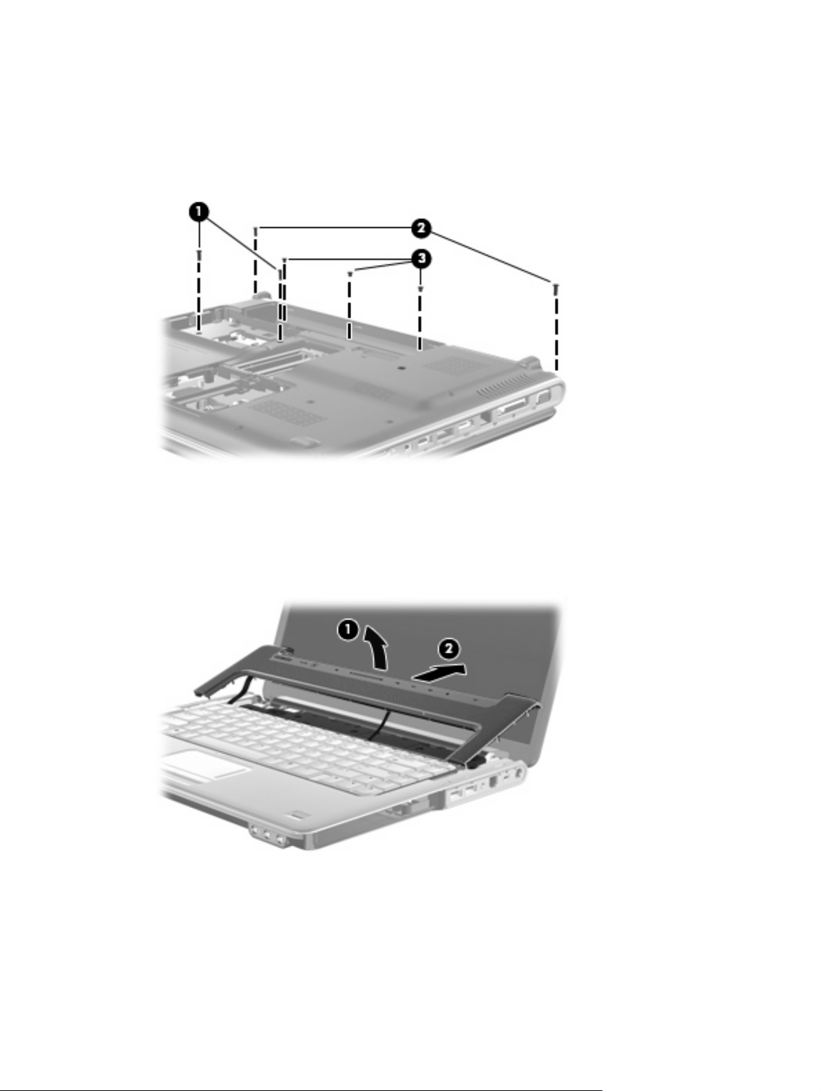
2. Remove the following screws:
(1) Two Phillips PM2.5×7.0 screws that secure the keyboard to the computer
(2) Two Phillips PM2.5×7.0 screws that secure the switch cover to the computer
(3) Three Phillips PM2.0×4.0 screws that secure the switch cover to the computer
3. Turn the computer display-side up, with the front toward you.
4. Open the computer as far as possible.
5. Lift the rear edge of the switch cover (1) until it detaches from the computer.
6. Slide the switch cover (2) back until it rests on the display.
70 Chapter 4 Removal and replacement procedures
Page 79

7. Remove the four Phillips PM2.0×4.0 screws that secure the keyboard to the computer.
8. Lift the rear edge of the keyboard (1) until it rests at an angle.
9. Slide the keyboard (2) back until the keyboard connector on the system board is accessible.
Component replacement procedures 71
Page 80
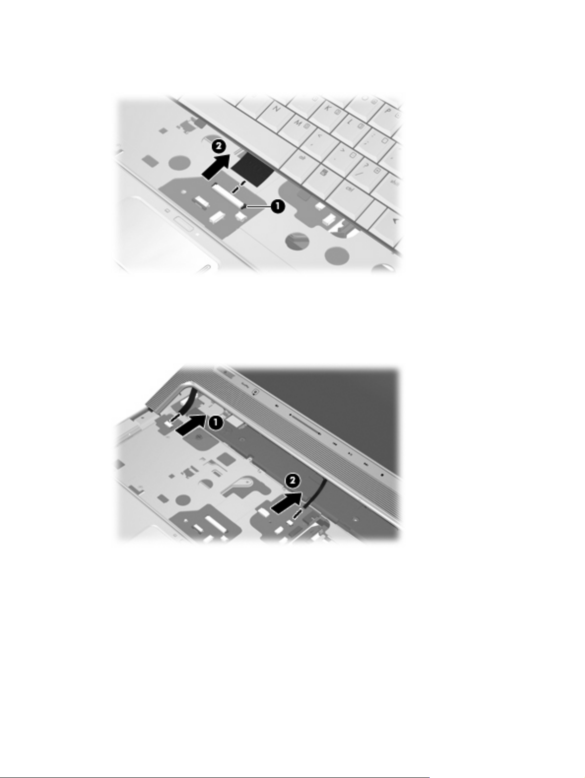
10. Release the zero insertion force (ZIF) connector (1) to which the keyboard cable is connected and
disconnect the cable (2) from the system board.
11. Remove the keyboard.
12. Disconnect the power button board cable (1) from the low insertion force (LIF) connector on the
system board.
13. Disconnect the LED board cable (2) from the LIF connector on the system board.
14. Remove the switch cover.
Reverse this procedure to install the switch cover and keyboard.
72 Chapter 4 Removal and replacement procedures
Page 81

Power button board
Description Spare part number
Power button board (includes cable) 486796-001
Before removing the power button board, follow these steps:
1. Shut down the computer. If you are unsure whether the computer is off or in Hibernation, turn the
computer on, and then shut it down through the operating system.
2. Disconnect all external devices connected to the computer.
3. Disconnect the power from the computer by first unplugging the power cord from the AC outlet and
then unplugging the AC Adapter from the computer.
4. Remove the battery (see
5. Remove the switch cover and keyboard (see
Battery on page 52).
Switch cover and keyboard on page 69).
Remove the power button board:
1. Turn the switch cover upside down with the front toward you.
2. Remove the Phillips PM2.0×4.0 screw (1) that secures the power button board to the switch cover.
3. Remove the power button board (2) and cable.
Reverse this procedure to install the power button board.
Component replacement procedures 73
Page 82

Speaker assembly
Description Spare part number
Speaker assembly 486801-001
Before removing the speaker assembly, follow these steps:
1. Shut down the computer. If you are unsure whether the computer is off or in Hibernation, turn the
computer on, and then shut it down through the operating system.
2. Disconnect all external devices connected to the computer.
3. Disconnect the power from the computer by first unplugging the power cord from the AC outlet and
then unplugging the AC adapter from the computer.
4. Remove the battery (see
5. Remove the switch cover and keyboard (see
Battery on page 52).
Switch cover and keyboard on page 69).
Remove the speaker assembly:
1. Disconnect the speaker assembly cable (1) from the system board.
2. Remove the speaker assembly cable from the clips (2) in the top cover.
3. Remove the speaker assembly (3).
Reverse this procedure to install the speaker assembly.
74 Chapter 4 Removal and replacement procedures
Page 83

Bluetooth module
NOTE: The Bluetooth module spare part kits do not include a Bluetooth module cable. The Bluetooth
module cable is available using spare part number 489822-001.
Description Spare part number
For use only with computer models equipped with AMD processors 412766-002
For use only with computer models equipped with Intel processors 483113-001
Before removing the Bluetooth module, follow these steps:
1. Shut down the computer. If you are unsure whether the computer is off or in Hibernation, turn the
computer on, and then shut it down through the operating system.
2. Disconnect all external devices connected to the computer.
3. Disconnect the power from the computer by first unplugging the power cord from the AC outlet and
then unplugging the AC Adapter from the computer.
4. Remove the battery (see
5. Remove the switch cover and keyboard (see
6. Remove the speaker assembly (see
Battery on page 52).
Switch cover and keyboard on page 69).
Speaker assembly on page 74).
Remove the Bluetooth module:
1. Remove the Phillips PM2.0×4.0 screw (1) that secures the Bluetooth module to the top cover.
2. Release the Bluetooth module (2) as far from the top cover as the Bluetooth module cable allows.
3. Disconnect the Bluetooth module cable (3) from the Bluetooth module.
4. Remove the Bluetooth module.
Reverse this procedure to install the Bluetooth module.
Component replacement procedures 75
Page 84

Display assembly
NOTE: All display assemblies include a webcam, 2 microphones, and 2 wireless antenna transceivers
and cables.
Description Spare part number
15.4-inch WSXGA+ AntiGlare display assembly 484372-001
15.4-inch WSXGA+ BrightView display assembly 484368-001
15.4-inch WXGA AntiGlare display assembly 484371-001
15.4-inch WXGA Brightview display assembly 484367-001
Before removing the display assembly, follow these steps:
1. Shut down the computer. If you are unsure whether the computer is off or in Hibernation, turn the
computer on, and then shut it down through the operating system.
2. Disconnect all external devices connected to the computer.
3. Disconnect the power from the computer by first unplugging the power cord from the AC outlet and
then unplugging the AC adapter from the computer.
4. Remove the battery (see
5. Disconnect the wireless antenna cables from the WLAN module (see
6. Remove the switch cover and keyboard (see
7. Remove the speaker assembly (see
Battery on page 52).
WLAN module on page 65).
Switch cover and keyboard on page 69).
Speaker assembly on page 74).
Remove the display assembly:
1. Disconnect the display panel cable (1) and the webcam/microphone cable (2) from the system
board.
76 Chapter 4 Removal and replacement procedures
Page 85
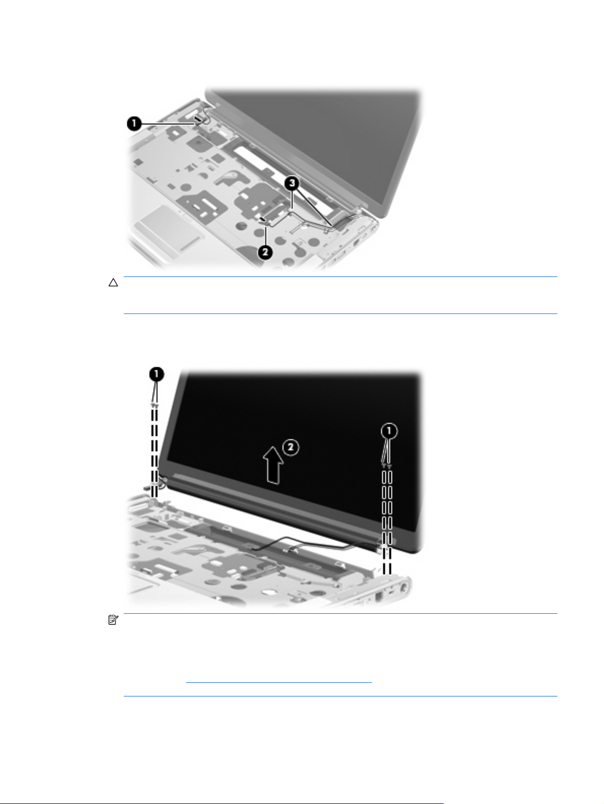
2. Remove the WLAN antenna cables from the clips (3) built into the top cover.
CAUTION: Support the display assembly when removing the following screws. Failure to support
the display assembly can result in damage to the display assembly and other computer
components.
3. Remove the four Phillips PM2.5×7.0 screws (1) that secure the display assembly to the computer.
4. Remove the display assembly (2).
NOTE: Steps 5 through 22 provide display assembly internal component removal information for
computer models equipped with AntiGlare display assemblies. See steps 23 through 32 for display
assembly internal component removal information for computer models equipped with BrightView
display assemblies.
NOTE: See Webcam/microphone module on page 53 for webcam/microphone module
replacement instructions for computer models equipped with BrightView display assemblies.
Component replacement procedures 77
Page 86

5. If it is necessary to replace the display enclosure or any of the display assembly internal
components, remove the following screw covers and screws:
(1) Two rubber screw covers on the display bezel bottom edge. The display rubber screw covers
are included in the Display Rubber Kit, spare part number 486537-001.
(2) Two Phillips PM2.5×7.0 screws.
6. Turn the display assembly upside down, with the bottom toward you.
7. Release the display enclosure (1) by sliding the enclosure toward the top of the display assembly.
8. Lift the display enclosure (2) as far as the display logo cable allows.
9. Disconnect the display logo cable (3) from the display panel cable.
10. Remove the display enclosure. The display enclosure is available using spare part number
485345-001, and includes the display logo LED board and the wireless antenna transceivers and
cables.
11. If it is necessary to replace the webcam/microphone module, remove the Phillips PM2.0×4.0
screw (1) that secures the module to the display bezel.
78 Chapter 4 Removal and replacement procedures
Page 87
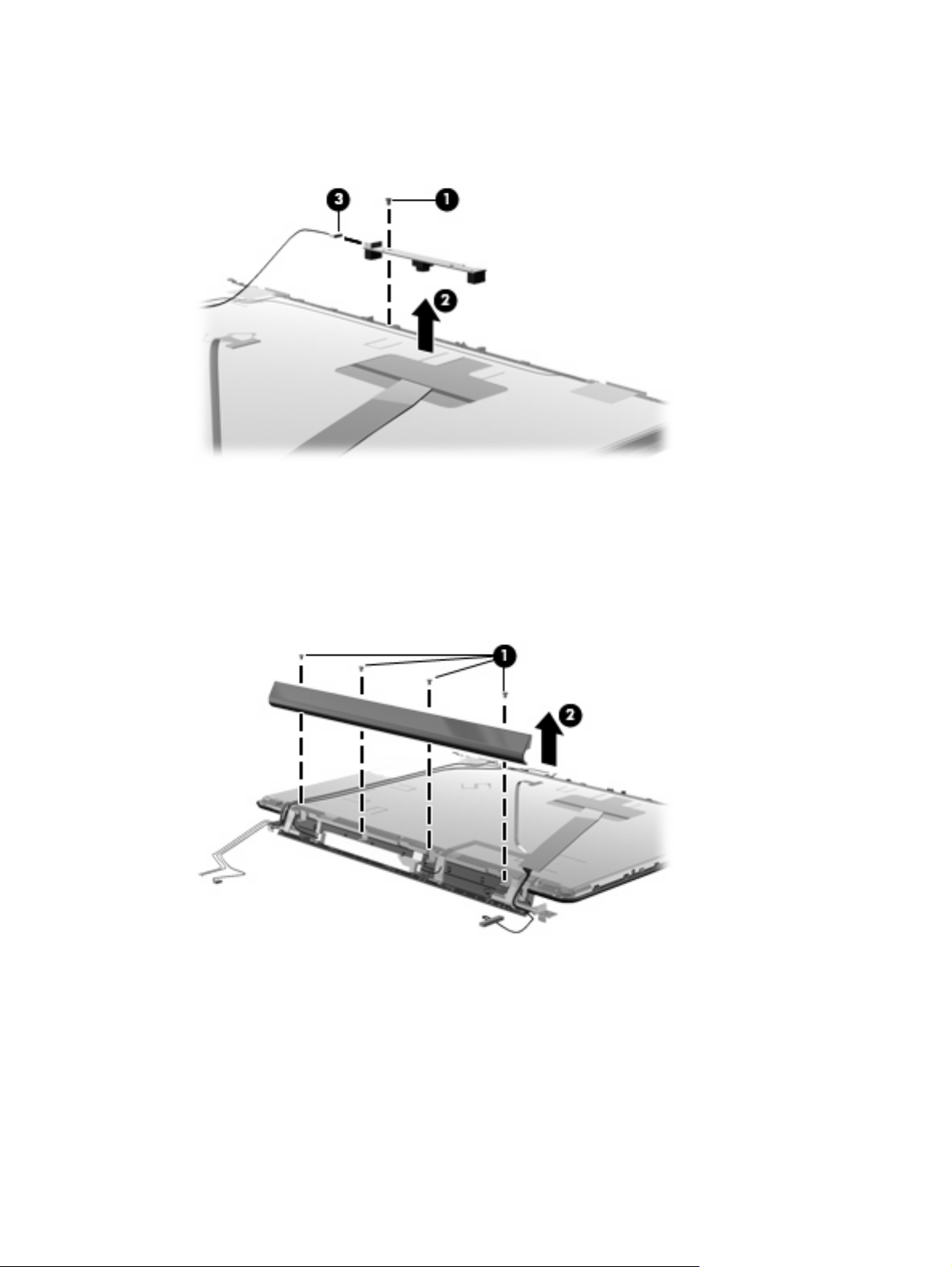
12. Release the webcam/microphone module (2) as far as the webcam/microphone module cable
allows.
13. Disconnect the webcam/microphone module cable (3) from the webcam/microphone module.
14. Remove the webcam/microphone module. The webcam/microphone module is available using
spare part number 485345-001.
15. If it is necessary to replace the display inverter, remove the four Phillips PM2.5×4.0 screws (1) that
secure the display inverter cover to the display bezel.
16. Remove the display inverter cover (2) by lifting it straight up. The display inverter cover is available
using spare part number 486792-001.
17. Release the display inverter (1) as far from the display bezel as far as the display panel cable and
backlight cable allow.
Component replacement procedures 79
Page 88
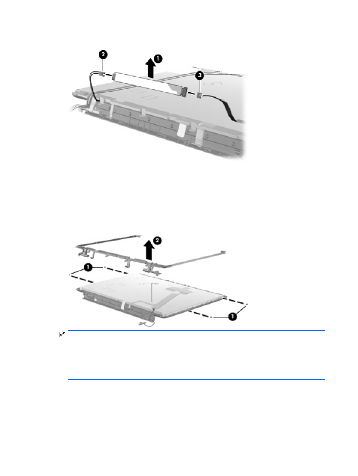
18. Disconnect the display panel cable (2) and backlight cable (3) from the display inverter.
19. Remove the display inverter. The display inverter is available using spare part number
488317-001.
20. If it is necessary to replace the display hinges, remove the four Phillips PM2.5×4.0 screws (1) that
secure the display hinges to the display panel.
21. Remove the display hinge (2) by lifting it straight up. The display hinge is available using spare part
number 485340-001.
NOTE: Steps 23 through 32 provide display assembly internal component removal information
for computer models equipped with BrightView display assemblies. See steps 5 through 22 for
display assembly internal component removal information for computer models equipped with
AntiGlare display assemblies.
NOTE: See Webcam/microphone module on page 53 for webcam/microphone module
replacement instructions for computer models equipped with BrightView display assemblies.
80 Chapter 4 Removal and replacement procedures
Page 89

22. If it is necessary to replace the display bezel or any of the display assembly internal components,
remove the following screw covers and screws:
(1) Two rubber screw covers on the display bezel bottom edge. The display rubber screw covers
are included in the Display Rubber Kit, spare part number 480442-001.
(2) Two Phillips PM2.5×7.0 screws.
23. Flex the inside edges of the top edge (1), the left and right sides (2), and the bottom edge of the
display bezel (3) until the bezel disengages from the display enclosure.
24. Remove the display bezel (4). The display bezel is available using the spare part number
486532-001.
25. If it is necessary to replace the display inverter, release the display inverter (1) as far from the
display enclosure as far as the display panel cable and backlight cable allow.
Component replacement procedures 81
Page 90

26. Disconnect the display panel cable (2) and the backlight cable (3) from the display inverter.
27. Remove the display inverter. The display inverter is available using spare part number
488317-001.
28. If it is necessary to replace the display panel, remove the six Phillips PM2.5×4.0 screws (1) that
secure the display panel to the display enclosure.
29. Remove the display panel (2). Display panels are available using spare part numbers 484363-001
(WSXGA+ BrightView display panel) and 484364-001 (WXGA BrightView display panel).
30. If it is necessary to replace the display hinges, remove the six Phillips PM2.0×4.0 screws (1) that
secure each display hinge to the display panel.
82 Chapter 4 Removal and replacement procedures
Page 91

31. Remove the display hinges (2). The display hinges are available in the Display Hinge Kit, spare
part 486534-001. The display hinge screws are available in the Display Hinge Kit Screw Kit, spare
part number 485344-001.
Reverse this procedure to reassemble and install the display assembly.
Component replacement procedures 83
Page 92
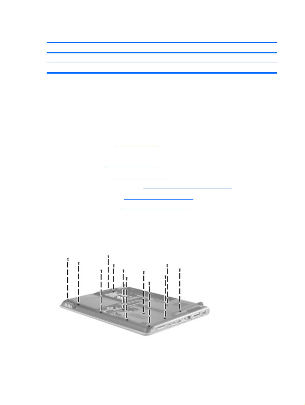
Top cover
Description Spare part number
For use only with computer models equipped with a fingerprint reader 486527-001
For use only with computer models not equipped with a fingerprint reader 486526-001
Before removing the top cover, follow these steps:
1. Shut down the computer. If you are unsure whether the computer is off or in Hibernation, turn the
2. Disconnect all external devices connected to the computer.
3. Disconnect the power from the computer by first unplugging the power cord from the AC outlet and
computer on, and then shut it down through the operating system.
then unplugging the AC adapter from the computer.
4. Remove the battery (see
Battery on page 52).
5. Remove the following components:
a. Hard drive (see
b. Optical drive (see
c. Switch cover and keyboard (see
d. Speaker assembly (see
e. Display assembly (see
Hard drive on page 62)
Optical drive on page 55)
Switch cover and keyboard on page 69)
Speaker assembly on page 74)
Display assembly on page 76)
Remove the top cover:
1. Turn the computer upside down, with the front toward you.
2. Remove the 12 Phillips PM2.5×7.0 screws that secure the top cover to the computer.
84 Chapter 4 Removal and replacement procedures
Page 93
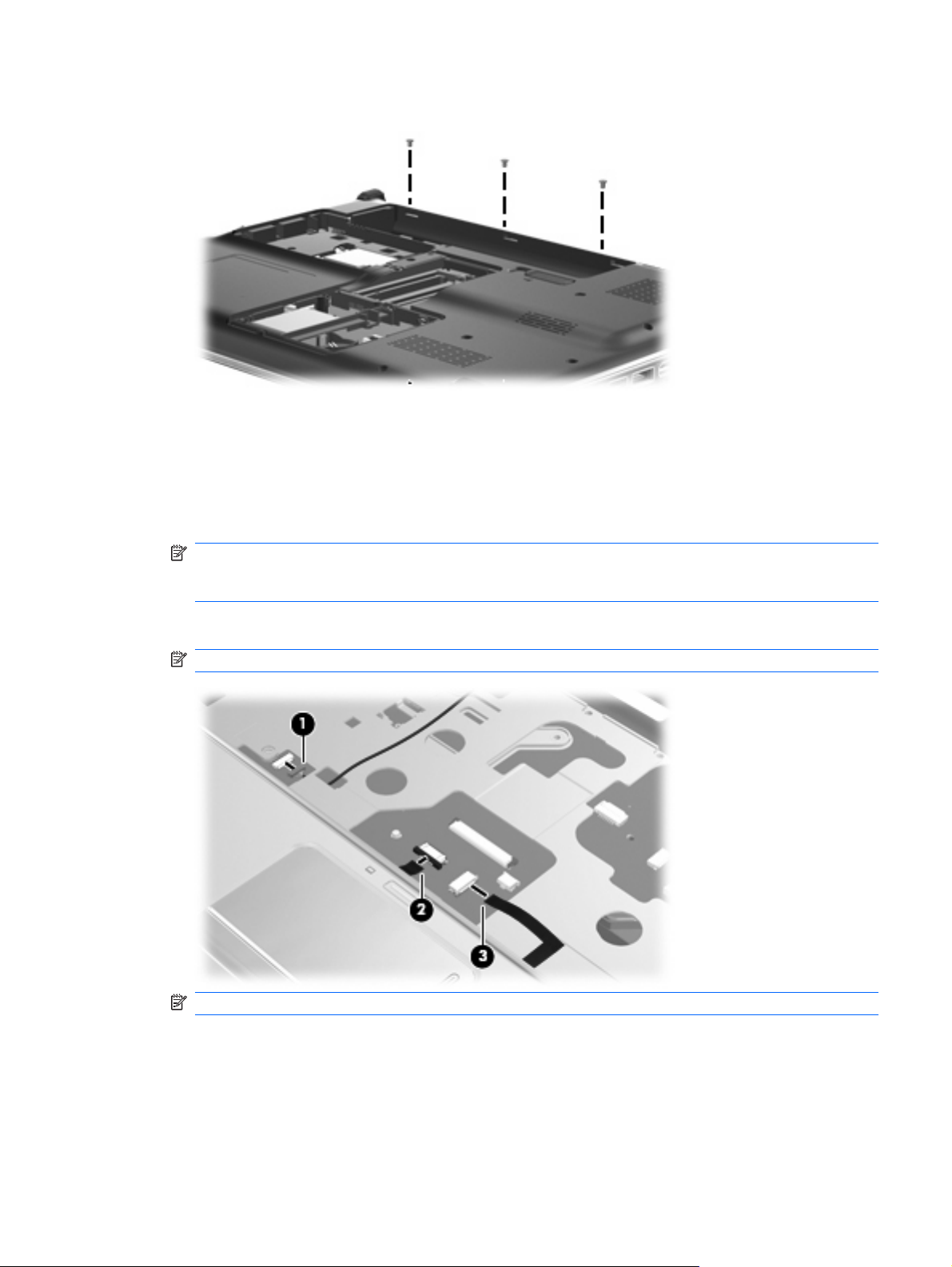
3. Remove the three Phillips PM2.5×4.0 screws secure the top cover to the computer.
4. Turn the computer right-side up, with the front toward you.
5. Disconnect the following cables from the system board:
(1) Bluetooth module cable
(2) TouchPad cable
NOTE: On computer models equipped with a standard display assembly, this cable connects to
a ZIF connector on the system board. On computer models equipped with a Flush Glass display
assembly, this cable connects to a LIF connector on the system board.
(3) Fingerprint reader board cable
NOTE: This cable connects to a LIF connector on the system board.
NOTE: Step 6 applies only to computer models equipped with standard display assemblies.
6. Remove the two Phillips PM2.5×7.0 screws (1) that secure the top cover to the computer.
Component replacement procedures 85
Page 94

7. Remove the two Phillips PM2.5×6.0 screws (2) that secure the top cover to the computer.
8. Lift the rear edge of the top cover (1) until it rests at an angle.
9. Remove the top cover (2) by lifting it straight up.
Reverse this procedure to install the top cover.
86 Chapter 4 Removal and replacement procedures
Page 95

Modem module
NOTE: The modem module spare part kits do not include a modem module cable. The modem module
cable is included in the Cable Kit, spare part number 501891-001. See
Cable Kit spare part number information.
Description Spare part number
Modem module for use in all countries and regions except Australia and New Zealand 461749-001
For use only in Australia and New Zealand 461749-011
Before removing the modem module, follow these steps:
1. Shut down the computer. If you are unsure whether the computer is off or in Hibernation, turn the
computer on, and then shut it down through the operating system.
2. Disconnect all external devices connected to the computer.
3. Disconnect the power from the computer by first unplugging the power cord from the AC outlet and
then unplugging the AC Adapter from the computer.
Cable Kit on page 31 for more
4. Remove the battery (see
Battery on page 52).
5. Remove the following components:
a. Hard drive (see
b. Optical drive (see
c. Switch cover and keyboard (see
d. Speaker assembly (see
e. Display assembly (see
f. Top cover (see
Hard drive on page 62).
Optical drive on page 55).
Switch cover and keyboard on page 69).
Speaker assembly on page 74).
Display assembly on page 76).
Top cover on page 84).
Remove the modem module:
1. Disconnect the modem module cable (1) from the modem module.
2. Remove the two Phillips PM2.0×4.0 screws (2) that secure the modem module to the system board.
Component replacement procedures 87
Page 96
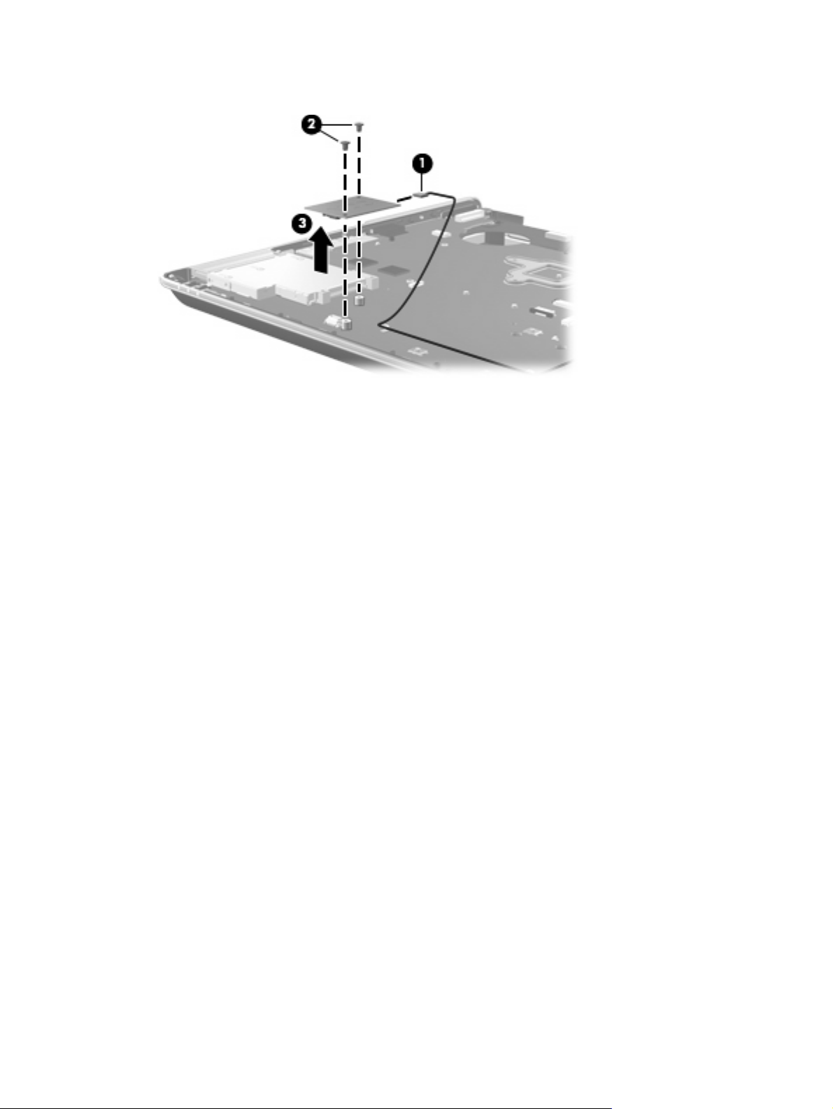
3. Lift the modem module (3) straight up to disconnect it from the system board.
Reverse this procedure to install the modem module.
88 Chapter 4 Removal and replacement procedures
Page 97
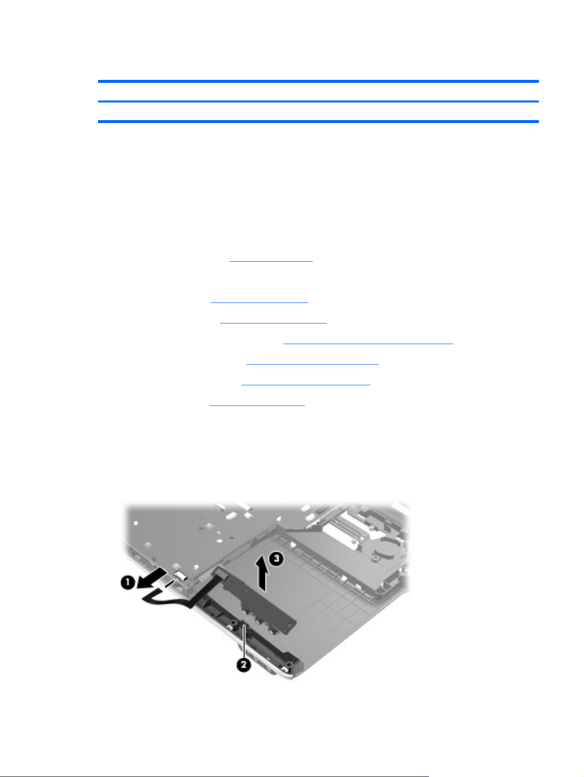
Audio/infrared board
Description Spare part number
Audio/infrared board (includes cable) 486797-001
Before removing the audio/infrared board, follow these steps:
1. Shut down the computer. If you are unsure whether the computer is off or in Hibernation, turn the
computer on, and then shut it down through the operating system.
2. Disconnect all external devices connected to the computer.
3. Disconnect the power from the computer by first unplugging the power cord from the AC outlet and
then unplugging the AC Adapter from the computer.
4. Remove the battery (see
Battery on page 52).
5. Remove the following components:
a. Hard drive (see
b. Optical drive (see
c. Switch cover and keyboard (see
d. Speaker assembly (see
e. Display assembly (see
f. Top cover (see
Hard drive on page 62).
Optical drive on page 55).
Switch cover and keyboard on page 69).
Speaker assembly on page 74).
Display assembly on page 76).
Top cover on page 84).
Remove the audio/infrared board:
1. Disconnect the audio/infrared board cable (1) from the LIF connector on the system board.
2. Release the clip (2) built into the base enclosure that secures the audio/infrared board.
3. Lift the audio/infrared board (3) straight up to remove it from the base enclosure.
Component replacement procedures 89
Page 98

Reverse this procedure to install the audio/infrared board.
USB board
Description Spare part number
USB board (includes cable) 486798-001
Before removing the USB board, follow these steps:
1. Shut down the computer. If you are unsure whether the computer is off or in Hibernation, turn the
2. Disconnect all external devices connected to the computer.
3. Disconnect the power from the computer by first unplugging the power cord from the AC outlet and
computer on, and then shut it down through the operating system.
then unplugging the AC Adapter from the computer.
4. Remove the battery (see
Battery on page 52).
5. Remove the following components:
a. Hard drive (see
b. Optical drive (see
c. Switch cover and keyboard (see
d. Speaker assembly (see
e. Display assembly (see
f. Top cover (see
Hard drive on page 62).
Optical drive on page 55).
Switch cover and keyboard on page 69).
Speaker assembly on page 74).
Display assembly on page 76).
Top cover on page 84).
Remove the USB board:
1. Disconnect the USB board cable (1) from the LIF connector on the system board.
2. Remove the Phillips PM2.5×7.0 screw (2) that secures the USB board to the base enclosure.
90 Chapter 4 Removal and replacement procedures
Page 99

3. Remove the USB board (3) from the base enclosure.
Reverse this procedure to install the USB board.
Component replacement procedures 91
Page 100

System board
NOTE: All system board spare kits include replacement thermal material.
Description Spare part number
For use only with computer models equipped with AMD processors:
With RX781 Northbridge and ATI-M82-S discrete graphics subsystem memory
With RS780 Northbridge and ATI-M UMA graphics subsystem memory 482325-001
For use only with computer models equipped with Intel processors:
With PM45 Northbridge and nVidia NB9P-GS discrete graphics subsystem memory
With PM45 Northbridge and nVidia NB9M-GE discrete graphics subsystem memory 482867-001
With GM45 Northbridge and UMA graphics subsystem memory 482869-001
With ICH9M Northbridge and UMA graphics subsystem memory 482868-001
482324-001
482870-001
Before removing the system board, follow these steps:
1. Shut down the computer. If you are unsure whether the computer is off or in Hibernation, turn the
computer on, and then shut it down through the operating system.
2. Disconnect all external devices connected to the computer.
3. Disconnect the power from the computer by first unplugging the power cord from the AC outlet and
then unplugging the AC adapter from the computer.
4. Remove the battery (see
Battery on page 52).
5. Remove the following components:
a. Hard drive (see
b. Optical drive (see
c. Switch cover (see
d. Speaker assembly (see
e. Display assembly (see
f. Top cover (see
Hard drive on page 62)
Optical drive on page 55)
Switch cover and keyboard on page 69)
Speaker assembly on page 74)
Display assembly on page 76)
Top cover on page 84)
When replacing the system board, be sure that the following components are removed from the defective
system board and installed on the replacement system board:
TV tuner module (see
●
RTC battery (see
●
Memory modules (see
●
WLAN module (see
●
Modem module (see
●
TV tuner module on page 57)
RTC battery on page 59)
Memory module on page 60)
Bluetooth module on page 75)
Modem module on page 87)
92 Chapter 4 Removal and replacement procedures
 Loading...