

Page 1
hp
hp p
hphp
pavilion
pp
avilion vvvv70
avilion avilion
d
display
dd
uuuuser's
ser's g
ser's ser's
70ssss
7070
isplay
isplayisplay
guide
uide
gg
uideuide
®
Page 2

The information contained in this document is subject to change without notice.
Hewlett-Packard® Company makes no warranty of any kind with regard to this material, including, but not limited to, the implied warranties of merchantability and fitness for a particular purpose.
HP shall not be liable for errors contained herein or for incidental or consequential damages in connection with the furnishing, performance , or use of this material.
HP assumes no responsibility for the use or reliability of its software on equipment that is not furnished by HP.
This document contains proprietary information that is protected by copyright. All rights are reserved. No part of this document may be photocopied, reproduced, or translated to another language without the prior written consent of HP.
Hewlett-Packard Company
Home Products Division
P.O. Box 4010
Cupertino, CA 95015-4010
Printed in the Taiwan
© Copyright Hewlett-Packard Company, 2000. All rights reserved.
Hewlett-Packard is a registered trademark of Hewlett-Packard Company in the United States of America and other countries.
The ENERGY STAR name is a U.S. Registered mark of the U.S. Environmental Protection Agency.
Other brand or product names are trademarks of their respective holders.
Page 3

Contents
Contents
ContentsContents
Introduction
Introduction................................
IntroductionIntroduction
Precautions
Precautions ................................
PrecautionsPrecautions
Features
Features................................
FeaturesFeatures
Specificatio ns
Specifications................................
Specificatio nsSpecificatio ns
Install in g th e Base Pedestal
Installing the Base Pedestal...............
Install in g th e Base PedestalInstall in g th e Base Pedestal
Control Locations and Functions
Control Locations and Functions ........
Control Locations and FunctionsControl Locations and Functions
Controls and Adjustments
Controls and Adjustments.................
Controls and AdjustmentsControls and Adjustments
....................................
................................................................
....................................
................................................................
.........................................
................................................................
....................................5555
................................................................
...............7777
..............................
.................9999
..................................
....1111
........
....2222
........
.........4444
..................
........8888
................
Connections
Connections................................
ConnectionsConnections
Pin Assignments and Signal Levels
Pin Assignments and Signal Levels ....
Pin Assignments and Signal LevelsPin Assignments and Signal Levels
Timing Charts
Timing Charts ................................
Timing ChartsTiming Charts
Troubleshooting
Troubleshooting..............................
TroubleshootingTroubleshooting
Automatic Power Saving
Automatic Power Saving ..................
Automatic Power SavingAutomatic Power Saving
Declaration of Conformity
Declaration of Conformity................
Declaration of ConformityDeclaration of Conformity
...................................
................................................................
................................ 11118888
................................................................
.............................. 21
............................................................
.................. 22222222
....................................
................ 22225555
................................
... 11115555
......
.... 11117777
........
21
2121
Contents
Contents
ContentsContents
II
IIIIII
IIII
Page 4

Introduction
Introduction
IntroductionIntroduction
Congratulations on your purchase of a HewlettPackard Multi-Frequency monitor. One of the
most versatile monitors available today, the v70s
automatically adjusts its vertical and h orizontal
scanning frequencies to those of your computer’s
graphics adapter. The v70s provides crisp text
and vivid color graphic displays when used with
Multi-Frequency and compatible graphics adapters
(see specifications) .
Introduction
Introduction
IntroductionIntroduction
1111
Page 5

Precautions
Precautions
PrecautionsPrecautions
To prevent electric shock do not remove
screws or back cover.
There are no user-serviceable parts inside
the monitor. Refer servicing to qualified
service personnel.
DO NOT REMOVE THE TILT/SWIVEL BASE!
The input power source:
The monitor is designed to be Full Range
from AC 100V to AC 240V.
Warning:
vvvv70s Monitor Guide
70s Monitor Guide
2222
70s Monitor Guide70s Monitor Guide
This appliance should be grounded.
Always connect the displ ay to a grounded,
three-prong power outlet. Use only the
factory-supplied power cord.
Do not put the monitor or other heavy objects
on the power supply cord. A dama ged
power cord may cause fire or electric shock.
Do not insert objects into the monitor.
They may cause fire or failure.
Do not allow liquids to fall into the cabin et.
Page 6

1111
To redu c e eye fa t i g u e, avoid u s i ng the display in direct sunlight or other bright lights.
off the power switch and then unplug the
monitor.
2222
Do not operate the monitor beyond the
specified temperature and humidity range
(see specifications) .
3333
For proper operation, keep the monitor adequately ventilated.
4444
Keep the monitor away from transformers, moto rs , fans or strong ma g netic fields.
5555
If the monitor does not operate properly, turn
6666
When an irregular supply is ap plied, a protection circuit will turn off the monitor (the power indicator will also be turned off) . I f this happens, turn off the power switch and wait at least 30 seconds before turn ing it on again.
Precautions
Precautions
PrecautionsPrecautions
3333
Page 7
Features
C
NOT CONNEC
Features
FeaturesFeatures
1111
Automatically scans horizontal frequencies ranged from 30kHz to 70kHz and vertical frequencies ranged from 50Hz to 120Hz.
SELF-TEST PATTERN
SELF-TEST PATTERN
SELF-TEST PATTERNSELF-TEST PATTERN
2222
Meets DPMS and NUTEK power-saving standards.
3333
All functions can be controlled by On-Screen Display.
4444
Plug-and-play compatibi lit y.
5555
Full-scan display – 15.9-inch diagonal viewable image size.
6666
Rotation (tilt c ont rol) .
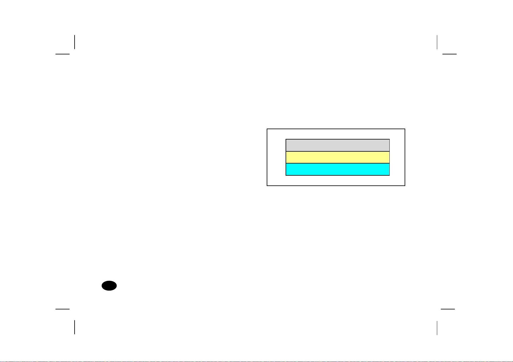
7777
Self-test –
from the PC, the display will produce as below
4444
vvvv70s Monitor Guide
Whe n you disco nne ct the signal cable
70s Monitor Guide
70s Monitor Guide70s Monitor Guide
ABLE
8888
Color temperature selection – 9 3 00K / 7000K / 6500K and user adjustable.
:
TED
Page 8

Specifications
Specifications
SpecificationsSpecifications
Power Source AC 100-240V, 50/60Hz
(Full Range)
Power 1111 Normal: 100W Max.
Consumption
2222 Stand-by Mode: <10W
3333 Suspend Mode: <10W
4444 Off Mode: <5W
Pic tur e Tub e 90deflection,
0.27mm dot pitch
15.9" Diagonal (viewable)
low radiation, glare,ligh t
transmission 53%
Maximum 1280 x 1024 at 60Hz
Resolution refresh rate
Input Signals
Video Analog 0.7 Vp-p /
75 ohm positive
Separate Sync positive / negative
Synchroniza tion
Horizontal 30KHz to 70KHz
Vertical 50Hz to 120Hz
Active Display
Area
Horizonta l 306mm typical
Vertical 230mm typical
Safety Stand ard UL / CSA
EMI Standard FCC Class B
Specifications
Specifications
SpecificationsSpecifications
5555
Page 9
Environmental
Conditions
Tilt and Swivel Operation:
Tilt and Swivel Operation:
Tilt and Swivel Operation:Tilt and Swivel Operation:
Operating 5°C~ 40°C
Temperature
Operating 10% ~ 80%
Humidity (non-condensing)
Storage -20°~ +60
Temperature
Storage 5% ~ 95%
Humidity
High Voltage 25KV
Dimensions 410mm x 422mm x 426 mm
(W x H x D)
Weight (Net ) 15.1 kg
°
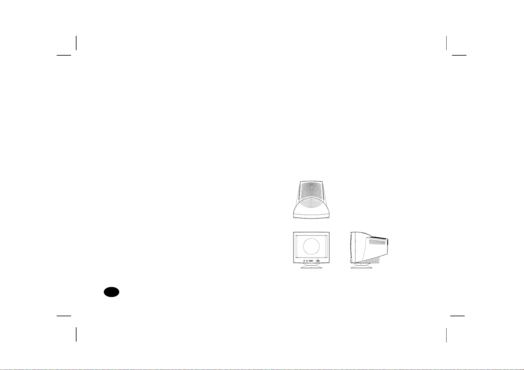
The swivel range is normally limited to 45
degrees to the right and the lef t of the front
position (marked by a small molded pip on the
top front of the base).
The tilt range is normal ly lim ited at an an gle of -5
degrees forwards and +15 degrees backwards.
This allows you to set the screen an gle to the
viewing position most comfortable to you.
vvvv70s Monitor Guide
70s Monitor Guide
6666
70s Monitor Guide70s Monitor Guide
Page 10

Installing the Base
Installing the Base
Installing the BaseInstalling the Base Pedestal
Pedestal
PedestalPedestal
1111
Turn the monitor upside down on a sturdy surface. (Don’t place i t screen-side down; the glass can be scratched.)
2222
Position the base pedestal with the latch facing the back of the monitor.
3333
Insert the seven tabs on the base pe destal into the seven slots found on the bot tom of the monitor.
4444
Push the base pedestal toward the front of the monitor un til it snaps into position.
Installallin g the Base Pedestal
Installallin g the Base Pedestal
Installallin g the Base PedestalInstallallin g the Base Pedestal
7777
Page 11

Control Locations and Functions
Control Locations and Functions
Control Locations and FunctionsControl Locations and Functions
Note:
Note:
Note:Note:
FRONT
FRONT
FRONTFRONT
Manual Degauss
Down/Brightness
Up/Contrast
8888
Locations of display controls are shown below.
Operation of controls is explained in the following
pages.
Select
vvvv70s Monitor Guide
70s Monitor Guide
70s Monitor Guide70s Monitor Guide
Power Sw it c h
Power Indica t or
REAR
REAR
REARREAR
Power Supply Connector Signal Cable
Page 12

Controls and Adjustments
A
A
/
/
/
Controls and Adjustments
Controls and AdjustmentsControls and Adjustments
1.
1. Power Indicator
1.1.
A. Th is in dicator will ligh t when the power is
on and the power cord is properly
connected.
B. The state of the LED is de pendent on the
power state of the monito r. When the LED
is green, the monitor is in th e normal
state. When it is amber, it indicates a
power - saving state.
3.
3. Direct access adjustments
3.3.
These adjustments can be called to the screen
only when the menu display is not present.
a. Press the button, a “c ontrast” horizontal
bar graph will appear, press either or
button to adjust upward or downward on
contrast.
CONTRAST 20 SEC
CONTRAST 20 SEC
CONTRAST 20 SECCONTRAST 20 SEC
2.
2. Power Sw itc h
2.2.
Press to power on the monitor; press again to
DJUST: / OK :
ADJUST:
power off.
We recommend powering your system on first,
then the moni tor.
DJUST: ADJUST:
OK :
OK :
OK :
Controls and Adjustments
Controls and Adjustments
Controls and AdjustmentsControls and Adjustments
100%
9999
Page 13

b. Press the button, a “brightness”
horizontal bar graph will appe ar, press
either or button to adjust upward
or downward on brightness.
BRIGHTNESS 20 SEC
BRIGHTNESS 20 SEC
BRIGHTNESS 20 SECBRIGHTNESS 20 SEC
1024
1024
768 68.7KHZ 85HZ
768 68.7KHZ 85HZ
10241024
768 68.7KHZ 85HZ768 68.7KHZ 85HZ
SIZE & POSITIO N
SHAPE
COLOR 9300K
MISCELLANEOUS
EXIT MENU 20SEC
50%
ADJUST:
ADJUST: / OK:
ADJUST: ADJUST:
4.
4. OSD MENU
4.4.
/ OK:
/ OK:/ OK:
Press “select” button to reveal the OSD main
menu, all adjustments and settings are covered
in the foll owing main menu display:
vvvv70s Monitor Guide
70s Monitor Guide
10
10
1010
70s Monitor Guide70s Monitor Guide
HORIZONTAL CENTERING
50%
MOVE:
MOVE: / SELECT:
MOVE: MOVE:
/ SELECT:
/ SELECT:/ SELECT:
The adjustment items writt en in the uppe r section
of the menu display and the lower section icon
contain a property which belongs to the arrowed
adjustment item.
You can select the adjustment items or it s
property which you may adjust or perform
settings by simply pressing either or button
to move the yellow graph to the desired item.
Page 14

Push the
will then enter the adjustment function. The
slide bar locating at the lower section becomes
red in color, pressing either or button to
adjust the settings that you desired.
After the adjustment is completed, push the
button once more to return to the normal OSD
menu.
EXIT MENU
Menu display will be closed automatically in 20 seconds.
Or select EXIT MENU and push the. button.
button once again, the OSD menu
Controls and Adjustments
Controls and Adjustments
Controls and AdjustmentsControls and Adjustments
11
11
1111
Page 15

ICON
g
ICON NAME
ICONICON
SIZE & POSITION
SIZE & POSITION
SIZE & POSITIONSIZE & POSITION
NAME FUNCTION
NAMENAME
Brightness
Contrast
FUNCTION ICON
FUNCTIONFUNCTION
To adjust the lu mi na n ce level in
the image
To adjust the difference in
lumina nce b etwee n lig ht and
dark areas of the image
ICON NAME
ICONICON
SHAPE
SHAPE
SHAPESHAPE
NAME FUNCTION
NAMENAME
Zoom
Tilt
FUNCTION
FUNCTIONFUNCTION
To enlarge or shrink the picture,
the default setting is 50% of the
slide bar
To adjust the display tilt
12
12
1212
Horizontal
centering
Width
Verti cal cent erin
Height
OSD move
OSD move
vvvv70s Monitor Guide
70s Monitor Guide
70s Monitor Guide70s Monitor Guide
To adjust the horizontal position
of the display
To adjust the width of the
display
To adjust the vertical position of
the display
To adjust the height of the
display
To enable the OSD menu to be
positione d horizontally
To enable the OSD menu to be
positioned vertically
Orthogonality
Trapezoid
Pincushion
Pin balance
To adjust the display squareness
To adjust the straightness of the
vertical edges of the display in
conjuncti o n wi t h t he pi n cushi on
control
To adjust the straightness of the
vertical edges of the display
To adjust the straightness of the
vertical edges of the display in
conjuncti on wit h pin cushio n and
trapezoid
Page 16

ICON
j
ICON NAME
ICONICON
COLOR
COLOR
COLORCOLOR
NAME FUNCTION
NAMENAME
Default color
FUNCTION ICON
FUNCTIONFUNCTION
To restore the color tint of the
background to 9300k
ICON NAME
ICONICON
MISCELLANEOUS
MISCELLANEOUS
MISCELLANEOUSMISCELLANEOUS
NAME FUNCTION
NAMENAME
About monitor
FUNCTION
FUNCTIONFUNCTION
Shows the properties of the
currently used display mode
<<<
>>>
Demagnetize
Monitor de fau lts
L
/Langue
VERT. MOIRE
HOR. MOIRE
anguage/Sprach e
Controls and Adjustments
Controls and Adjustments
Controls and AdjustmentsControls and Adjustments
Color presets
R
Red value
G
S
B
Green value
Blue value
Save current
color
To select the desired 3 fixed
(9300k, 7000k, 6500k )
background tint and an
adjustable custom setting by
pushing the ↵ select button
To ad
ust the red magnitude when
color preset selects “custom”
definable setting
To adjust the green magnitude
when color preset selects
“custom” definable setting
To adjust the blue magnitude
when color preset selects
“custom” definable setting
To store the current custom
settings of the color ti n
EXIT MENU
EXIT MENU
EXIT MENUEXIT MENU
To manually degauss the display
Recalls the original factory display
presettings
Menu lang uage selec tion, tota lly 5
languages
To reduce the vertical wavy
colored li nes o r patterns in t he
background of your image
To r ed uce t he ho r izont al wavy
colored li nes o r patterns in t he
background of your image
To r emove the displa y o f OSD
menu
13
13
1313
Page 17

5.
5. ME NU LA N GUAGE
MENU LANGUAGE
5. 5.
MENU LANGUAGEMENU LANGUAGE
To select the Menu Language in the
Miscellaneous Menu, the Language menu will
be displayed.
MENU LANGUAGE
MENU LANGUAGE
ENGLISH
DEUTSCH
ITALIANO
FRANÇAIS
ESPAÑOL
CANCEL
MOVE:
MOVE: / SELECT:
MOVE: MOVE:
MENU LANGUAGEMENU LANGUAGE
/ SELECT:
/ SELECT:/ SELECT:
Pressing either or key to select the desred
language, then push th e
“select” key, thus the OSD menu appears
with the chosen language.
14
14
1414
vvvv70s Monitor Guide
70s Monitor Guide
70s Monitor Guide70s Monitor Guide
Page 18

Connections
Connections
ConnectionsConnections
Your monitor has two connecting cabl es : a Power
Supply Cord, which connects to a wall outlet,
surge protector or other power source, and a
Signal Cable, which connects to the graphics
adapter of your compute r. To ensure safety and
correct operation, always follow these four st e p s
when connecting the monitor:
1111
Make sure the monitor a nd computer are turned off. (See previous section on safety.)
2222
Connect the power cord to the back of the display.
3333
Plug the other end of the cabl e into a grounded outlet.
4444
Connect the video cab le on the monitor to the 15-pin video graphics connector on the rear panel of the computer, and fasten the screws.
(If you have an HP Pavilion computer, this port is
marked in orange. For other computers, check
your computer manual for the video port
location.)
Note:
Note:
Note:Note:
Don’t force the cable into the connector; line it up
carefully so you don’t bend the pins.
Connections
Connections
ConnectionsConnections
15
15
1515
Page 19

Connecting the Speakers
Connecting the Speakers
Connecting the SpeakersConnecting the Speakers
The display is designed for use with speakers
supplied with HP Pavilion computers.
To connect the speakers:
1111
Identify th e lef t and right speakers. You can
tell which side a speaker fits onto by its
mounting pegs. The side of the speaker with
mounting pegs fits ag ain st th e side of the
display.
2222
Fit the pegs of the right speaker into the
corresponding holes on the right side of the
display.
3333
With the pegs in th e corresponding holes, til t
the speaker toward the front of the monitor
and push down until the spea ker is secure.
4444
Repeat procedure for left speaker and push
down until speaker is secured.
Tilt spea kers toward
front and push down
Refer to your computer setup poster for
instructions to connect your speaker to the PC.
16
16
1616
vvvv70s Monitor Guide
70s Monitor Guide
70s Monitor Guide70s Monitor Guide
Page 20

Pin Assignments and Signal Levels
Pin Assignments and Signal Levels
Pin Assignments and Signal LevelsPin Assignments and Signal Levels
15-Pin D-SUB male video conn ector
15-Pin D-SUB male video conn ector
15-Pin D-SUB male video conn ector15-Pin D-SUB male video conn ector
SIGN AL L EVEL
SIGN AL L EVEL
SIGN AL L EVELSIGNAL LE VEL
1
6
Note:
Note:
11
PIN N O.
PIN NO. SIGNAL
PIN N O.PIN NO.
1RED 9NC
2GREEN 10DIGITAL GROUND
3 BLUE 11 MONITOR SENSEI
4 DIGITAL GROUND 12 SDA (DDC1/2B)
5 RETURN (DDC2B) 13 H. SYNC.
6GROUND 14V. SYNC.
7 GROUND 15 SCL (DDC2B)
8GROUND
SIG N A L PIN NO.
SIGNALSIGNAL
PIN N O. SI GNAL
PIN N O.PIN NO.
SIGNAL
SIGNALSIGNAL
Note:Note:
The signal level at pin 1,2,3 is 0.7 Vp-p.
The signal level at pin 13,14 is 5 Vp-p.
Pin Assignments and Signal Levels
Pin Assignments and Signal Levels
Pin Assignments and Signal LevelsPin Assignments and Signal Levels
17
17
1717
Page 21

Timing C ha rts
V
V
Timing C ha rts
Timing C ha rtsTiming C ha rts
SEPARATE SYNC.
SEPARATE SYNC.
SEPARATE SYNC.SEPARATE SYNC.
HORIZONTAL
ERTICAL
18
18
1818
Hor. Video
Hor. Sync.
Ver t . V i d e o
ert. Sync.
vvvv70s Monitor Guide
70s Monitor Guide
70s Monitor Guide70s Monitor Guide
E
Page 22

FACTOR Y MODES
FACTOR Y MODES
FACTOR Y MODESFACTOR Y MODES
Mode No.
Mode No. 11112
Mode No.Mode No.
23
22
34
33
45
44
5Unit
55
Unit
UnitUnit
Resolution
Horizontal Frequency
(A) Horizontal
(B) Horizontal Pulse Width
(C) Horizontal Back Porch
(D) Horizontal Active Area
(E) Horizontal Front Porch
(F) H. Sync. Polarity
Vert ic al Fr eq ue nc y
(O) Vertical Period
(P) Vertical Pulse Width
(Q) Vertical Back Porch
(R) Vertical Active Area
(S) Vertical Front Porch
(T) V. Sync. Polarity
(U) Interlaced
720 x 400
31.468
31.780
3.814
1.907
25.423
0.636
–
70.000
14.269
0.064
1.08
12.712
0.413
+
No
640 x 480
31.468
31.778
3.813
1.907
25.422
0.636
–
59.940
16.683
0.064
1.049
15.253
0.318
–
No
640 x 480
37 .500
26.667
2.032
3.810
20.318
0.18
–
75.000
13.333
0.08
0.427
12.800
0.027
–
No
800 x 600
37 .879
26.4
3.2
2.2
20.2
1.0
+
60.31
16.579
0.1056
0.607
15.84
0.0264
+
No
640 x 480
43.269
23. 111
1.556
2.222
17.778
1.556
–
85.0
11.764
0.069
0.578
11.093
0.023
–
No
KHz
usec
usec
usec
usec
usec
Hz
msec
msec
msec
msec
msec
Timi ng Ch arts
Timi ng Ch arts
Timi ng Ch artsTiming Ch arts
19
19
1919
Page 23

FACTOR Y MODES
FACTOR Y MODES
FACTOR Y MODESFACTOR Y MODES
Mode No.
Mode No. 66667
Mode No.Mode No.
78
77
89
88
910
99
10 Unit
1010
Unit
UnitUnit
Resolution
Horizontal Frequency
(A) Horizontal
(B) Horizontal Pulse Width
(C) Horizontal Back Porch
(D) Horizontal Active Area
(E) Horizontal Front Porch
(F) H. Sync. Polarity
Vert ic al Fr eq ue nc y
(O) Vertical Period
(P) Vertical Pulse Width
(Q) Vertical Back Porch
(R) Vertical Active Area
(S) Vertical Front Porch
(T) V. Sync. Polarity
(U) Interlaced
vvvv70s Monitor Guide
70s Monitor Guide
20
20
2020
70s Monitor Guide70s Monitor Guide
800 x 600
46.875
21.333
1.616
3.232
16.162
0.323
+
75.000
13.333
0.064
0.448
12.800
0.021
+
No
1024 x 768
48.363
20.677
2.092
2.462
15.754
0.369
–
60.00
16.666
0.124
0.600
15.88
0.062
–
No
800 x 600
53.674
18.631
1.138
2.702
14.222
0.702
–
85.061
11.756
0.056
0.503
11.179
0.019
+
No
1024 x 768
56.476
17 .707
1.813
1.92
13.653
0.521
–
70.069
14.272
0.106
0.513
13.599
0.054
–
No
1024 x 768
68.677
14.561
1.013
2.2
10.836
0.471
+
85
11.764
0.044
0.524
11.182
0.014
+
No
KHz
usec
usec
usec
usec
usec
Hz
msec
msec
msec
msec
msec
Page 24

Troubleshooting
Troubleshooting
TroubleshootingTroubleshooting
Before you call an authorized service center, please
check if the following items are properly connected.
If a nonstandard personal computer or graphics
PROBLEM CHECKS LOCATION
No picture or
POWER i ndicato r off.
No picture, POWER indicator off,
AC cord plugged in, POWER switch on. Least 30 seconds, turn it back on.
Image is n ot centered.
No picture, POWER indicator on.
AC cord plugged in Rear
POWER switch on Front
Signal cable connected Rear
Turn off POWER switch, wait at Front
V-CENTERING Control Front
H-PHASE Control Front
CONTRAST Con trol Front
BRIGHTNESS Control Front
adapter is being used, make sure the pin assignments
of the signal input connector and the signal timing
meet the specifications detailed previously.
Troubleshooting
Troubleshooting
TroubleshootingTroubleshooting
21
21
2121
Page 25

Automatic Power Saving
Automatic Power Saving
Automatic Power SavingAutomatic Power Saving
Introduction
Introduction
IntroductionIntroduction
“Green Concept” has prevailed throughout the
information market of the world for some years.
EPA (Environmental Pro tection Agency) stipulates
that all information products sold to the UNITED
STATES should meet the requirement of
environmental protection. Thus, we promote a
series of monitors with power-saving features
which meet the “EPA” energy star requirement.
Below are the criteria:
Features
Features
FeaturesFeatures
When the moni tor is connected to an
unpowered PC or when both horizontal and
vertical syncs are not present, the monitor will
enter the “o ff ” state and the power LED will be
amber.
When either horizontal or vertical sync is
absent, the
“Suspend” or “Stand-by” state and the power
LED color will be yellow.
When the PC recovers from the sleep state by
either operation of the keyboard or mouse, the
monitor will power up normally and the power
LED will be green.
Power C onsumption
Power C onsumption
Power C onsumptionPower C onsumption
The monitor power is reduced to less than 5
Watts in the power save “OFF” state and meets
the U.S.A “EPA” energy star requirement and
VESA “DPMS” requirement.
monitor will automatically enter the
22
22
2222
v70s Monitor Guide
Page 26

Federal Communications Commission Notice
Federal Communications Commission Notice
Federal Communications Commission NoticeFederal Communications Commission Notice
This equipm ent has been teste d an d foun d t o com ply with
the limi ts for a Class B dig i tal device purs uant to Part 15 of
the FCC Rules. These limits are designed to provide
reasonable protection against harmful interference in a
residential installation. This equipment generates, uses, and
can radiate radi o frequen cy e nergy an d, if not insta lle d
and used in accordance with the instructions, may cause
harmful inter ference t o radio communications. However,
there is no guarantee that interference will not o ccur in a
particular installation. If this equipment does cause harmful
interference to radio or television reception, which can be
determined by turning the equipment off and on, the user
is encouraged to try to correct the interference by one or
more of the following measures:
Reorient or relocate the receiving antenna.
Increase the separation between the equipment and the
receiver.
Connect the equi pment into an outl et on a circuit
different from that to which the receiver is connecte d.
Consult the dealer or an experienced radio or television
technician for help.
X-Ray Radiation Notice
X-Ray Radiation Notice
X-Ray Radiation NoticeX-Ray Radiation Notice
When operating, this product emi ts X- rays; however, it is
well shielded and meets the safety and health requirements
of various countries, such as the Radiation Act of Germany
and the Radiation Control for Health and Safety Act of the
United States.
Radiation emitted by this product is less than 0.1mR /hr (1
Sv/hr) at a distance of 10 centimeters from the surface of
the cathode-ray tube. The x-ray radiation primarily
depends on the characteri stics of th e cath od e - ray tube and
its associated low-voltage and high-voltage circuitry.
Internal controls have been a djusted to ens ure safe
operation. Only qualified personnel should perform any
internal adjustments, as specified in the service manual for
this product.
Replace t he cathode-ray tube with an identical CRT on ly.
Cables
Cables
CablesCables
Connections to this device must be made with shielded
cables with metal lic REI/ EMI conn ecto r hoo ds to m aint ain
compliance with FCC Rules and Regulations.
Canadian Notice
Canadian Notice
Canadian NoticeCanadian Notice
This Class B dig it al app aratus me ets a ll requirements of th e
Canadian In t er fe rence - Causin g Equi pment Regula tion s.
µ
Auto m a t i c Power Savi ng
Auto m a t i c Power Savi ng
Auto m a t i c Power Savi ngAutoma t i c Power Savi ng
23
23
2323
Page 27

Avis
Avis Ca na d ie n
Canad ien
Avis Avis
Canad ienCan adien
Cet appareil numérique de la classe B respecte toutes les
exigences du Réglement sur le matériel brouilleur du Canada.
EPA Energy Star
EPA Energy Star
EPA Energy StarEPA Energy Star
Monitors that are marked with the Energy Star logo meet the
requirements of the EPA Energy Star program. Specific details
on using the En ergy Star feat ures can b e found in th e energy
saver or power management section of the manual that comes
with the c om p ute r th e monitor is con n e cte d t o.
Product names mentioned herein may be trademarks and / or
registered trademarks of their respective companies.
24
24
2424
vvvv70s Monitor Guide
70s Monitor Guide
70s Monitor Guide70s Monitor Guide
Page 28

Declaration of
Declaration of
Declaration ofDeclaration of
Conformity
Conformity
ConformityConformity
Manufacturer
Manufacturer’’’’s Name:
ManufacturerManufacturer
Manufacturer
Manufacturer’’’’s Address:
ManufacturerManufacturer
Declares that the product
Declares that the product
Declares that the productDeclares that the prod uct
Product Name:
Product Name: HP Pavilion v70s Multimedia Display
Product Name:Product Name:
Model Number:
Model Num ber: P39 02X (where X=A…Z)
Model Number:Model Number:
Conforms to the following Product Specifications:
Safety:
Safety: IEC 60950:1991+A1+A2+A3+A4
Safety:Safety:
EMC:
EMC: CISPR 22:1993+A 1+A2/ EN 55022:1994+A1+A2-Class B
EMC:EMC:
s Name: Hewlett-Packard Company
s Name:s Name:
s Address: 10500 Ridgeview Ct.
s Address:s Address:
Cupertin o, CA 95015 USA
EN 60950:1992+A1+A2+A3+A4+A11
EN 50082-1:1992-Gen e ric lmmunity
IEC 801-2:1991/ prEN 55024-2:1992-4kV CD,8kV AD
IEC 801-3:1984/ prEN 55024-3:1991-3V/m
IEC 801-4:1988/ prEN 55024-4:1993-0.5kV Signal Lines.
1kV Power Lines.
2)
FCC Title 47 CFR, Part 1 5 Class B
/ ICES-002,lssue2
Supplementary
Supplementary lnformation:
Supplementary Supplementary
The product herewith complies with the requirements of the Low
Voltage Directive 73/23/EEC and the EMC
Di rective 89/336/EEC and carries the CE-mark ing accordingl y.
1)The product was tested in a typical configuration with a Hewlett
Packard Personal Computer and Peripherals.
2)This Device complies with Part 15 of th e FCC Rules. Oper a tion is
subject to the following two Conditions:
(1) thi s device may no t c ause ha rmful inte rfe rence, and
(2) this devlce must acce pt any inter ference received, including
interference that may cause undesired operation.
Cupertino, CA USA
Cupertino, CA USA De ce mbe r
Cupertino, CA USA Cupertino, CA USA
1)
For Regulatory Compliance lnformation ONLY, contact:
European c on tac t :
European contact: for regulatory topics only: Hewlett-Packard GmbH,
European c on tac t :European contact:
USA Contact:
USA Contact: Hardware Quality Eng. Manager, Hewlett-Packard
USA Contact:USA Conta ct :
lnformation:
lnformation:lnformation:
December,
DecemberDecember
HQ-TRE, Herre nberger Straße 110-140, D-71034
Bölingen (FAX:+49-7031-14-3143).
Company, HPD, 10500 Ridgeview Ct, Cupertino , C A
95015-4010. Phone: (408)-343-5000
, 2000 Quality Engi neering Manager
2000 Quality Engineering Manager
, ,
2000 Quality Engineering Manager2000 Quality Engineering Manager
Declaration of
Declaration of Conform it y
Declaration ofDeclaration of
Conformity
ConformityConformity
25
25
2525
Page 29

 Loading...