

HP Pavilion 17-g099, Pavilion 17-g000 Maintenance And Service Manual

HP Pavilion Notebook (AMD)
Maintenance and Service Guide

© Copyright 2015 Hewlett-Packard
Development Company, L.P.
AMD and Radeon are trademarks of Advanced
Micro Devices, Inc. Bluetooth is a trademark
owned by its proprietor and used by HewlettPackard Company under license. Microsoft and
Windows are U.S. registered trademarks of the
Microsoft group of companies. SD Logo is a
trademark of its proprietor.
The information contained herein is subject to
change without notice. The only warranties for
HP products and services are set forth in the
express warranty statements accompanying
such products and services. Nothing herein
should be construed as constituting an
additional warranty. HP shall not be liable for
technical or editorial errors or omissions
contained herein.
First Edition: April 2015
Document Part Number: 807552-001
Product notice
This guide describes features that are common
to most models. Some features may not be
available on your computer.
Not all features are available on all editions of
Windows 8.1. This computer may require
upgraded and/or separately purchased
hardware, drivers, and/or software to take full
advantage of Windows 8.1 functionality. See
http://www.microsoft.com for details.

Safety warning notice
WARNING! To reduce the possibility of heat-related injuries or of overheating the device, do not place the
device directly on your lap or obstruct the device air vents. Use the device only on a hard, flat surface. Do not
allow another hard surface, such as an adjoining optional printer, or a soft surface, such as pillows or rugs or
clothing, to block airflow. Also, do not allow the AC adapter to contact the skin or a soft surface, such as
pillows or rugs or clothing, during operation. The device and the AC adapter comply with the user-accessible
surface temperature limits defined by the International Standard for Safety of Information Technology
Equipment (IEC 60950-1).
iii

iv Safety warning notice

Table of contents
1 Product description ....................................................................................................................................... 1
2 External component identification ................................................................................................................. 5
Display ................................................................................................................................................................... 5
Right side ............................................................................................................................................................... 8
Left side ................................................................................................................................................................. 9
Top ....................................................................................................................................................................... 10
TouchPad ........................................................................................................................................... 10
Lights ................................................................................................................................................. 11
Buttons and speakers ....................................................................................................................... 12
Bottom ................................................................................................................................................................. 13
Labels ................................................................................................................................................................... 14
3 Illustrated parts catalog .............................................................................................................................. 15
Computer major components ............................................................................................................................. 15
Display assembly subcomponents, non-touch models ..................................................................................... 19
Display assembly subcomponents, touch models ............................................................................................. 21
Miscellaneous parts ............................................................................................................................................. 22
Mass storage devices .......................................................................................................................................... 23
4 Removal and replacement procedures preliminary requirements .................................................................... 25
Tools required ...................................................................................................................................................... 25
Service considerations ........................................................................................................................................ 25
Plastic parts ....................................................................................................................................... 25
Cables and connectors ...................................................................................................................... 25
Drive handling ................................................................................................................................... 26
Grounding guidelines ........................................................................................................................................... 26
Electrostatic discharge damage ....................................................................................................... 26
Packaging and transporting guidelines ......................................................................... 27
Workstation guidelines ................................................................................ 27
5 Removal and replacement procedures for Customer Self-Repair parts ............................................................. 29
Component replacement procedures ................................................................................................................. 29
Battery ............................................................................................................................................... 29
Optical drive ...................................................................................................................................... 30
v

6 Removal and replacement procedures for Authorized Service Provider parts ................................................... 33
Component replacement procedures ................................................................................................................. 33
Bottom cover ..................................................................................................................................... 34
Hard drive .......................................................................................................................................... 37
WLAN module .................................................................................................................................... 38
RTC battery ........................................................................................................................................ 40
Memory module ................................................................................................................................ 41
Fan ..................................................................................................................................................... 42
Heat sink assembly ........................................................................................................................... 43
USB board .......................................................................................................................................... 46
Optical drive connector ..................................................................................................................... 47
System board .................................................................................................................................... 48
Speakers ............................................................................................................................................ 51
Power button board .......................................................................................................................... 52
Power connector cable ...................................................................................................................... 53
TouchPad ........................................................................................................................................... 54
Display assembly, non-touch ........................................................................................................... 56
Display assembly, touch ................................................................................................................... 62
7 Using HP PC Hardware Diagnostics (UEFI) ...................................................................................................... 67
Downloading HP PC Hardware Diagnostics (UEFI) to a USB device .................................................................... 67
8 Using Setup Utility (BIOS) in Windows 8.1 ...................................................................................................... 69
Starting Setup Utility (BIOS) ................................................................................................................................ 69
Updating the BIOS ................................................................................................................................................ 69
Determining the BIOS version ........................................................................................................... 69
Downloading a BIOS update .............................................................................................................. 70
Synchronizing a tablet and keyboard (select models only) ............................................................................... 71
9 Using Setup Utility (BIOS) in Windows 7 ......................................................................................................... 73
Starting Setup Utility (BIOS) ................................................................................................................................ 73
Updating the BIOS ................................................................................................................................................ 73
Determining the BIOS version ........................................................................................................... 73
Downloading a BIOS update .............................................................................................................. 73
10 Backing up, restoring, and recovering in Windows 8.1 .................................................................................. 75
Creating recovery media and backups ................................................................................................................ 75
Creating HP Recovery media (select models only) ........................................................................... 75
Using Windows tools ........................................................................................................................................... 76
Restore and recovery .......................................................................................................................................... 76
vi

Recovering using HP Recovery Manager .......................................................................................... 77
What you need to know before you get started ............................................................ 77
Using the HP Recovery partition (select models only) .................................................. 78
Using HP Recovery media to recover ............................................................................. 78
Changing the computer boot order ................................................................................ 79
Removing the HP Recovery partition (select models only) ........................................... 79
11 Backing up, restoring, and recovering in Windows 7 ..................................................................................... 81
Creating backups ................................................................................................................................................. 81
Creating recovery media to recover the original system ................................................................. 81
What you need to know .................................................................................................. 81
Creating the recovery media ........................................................................ 82
Creating system restore points ........................................................................................................ 82
What you need to know .................................................................................................. 82
Creating a system restore point ..................................................................................... 82
Backing up system and personal information .................................................................................. 82
Tips for a successful backup ........................................................................................... 83
What you need to know .................................................................................................. 83
Creating a backup using Windows Backup and Restore ................................................ 83
Restore and recovery .......................................................................................................................................... 84
Restoring to a previous system restore point .................................................................................. 84
Restoring specific files ...................................................................................................................... 84
Restoring specific files using Windows Backup and Restore ......................................... 84
Recovering the original system using HP Recovery Manager .......................................................... 84
What you need to know .................................................................................................. 84
Recovering using HP Recovery partition (select models only) ...................................... 85
Recovering using the recovery media ............................................................................ 85
Changing the computer boot order .............................................................. 85
12 Specifications ........................................................................................................................................... 87
Computer specifications ...................................................................................................................................... 87
39.6-cm (15.6-in) display specifications ............................................................................................................ 88
Hard drive specifications ..................................................................................................................................... 89
Blu-ray ROM DVD±RW SuperMulti DL Drive ........................................................................................................ 90
DVD±RW SuperMulti DL Drive specifications ...................................................................................................... 91
13 Power cord set requirements ...................................................................................................................... 93
Requirements for all countries ........................................................................................................................... 93
Requirements for specific countries and regions ............................................................................................... 94
vii

14 Recycling .................................................................................................................................................. 97
Index ............................................................................................................................................................. 99
viii

1 Product description
Category Description
Product name HP Pavilion Notebook
Processors AMD Quad-Core A-Series Accelerated Processor (Carrizo, BGA)
A8-7410 (2.2 GHz, up to 2.5GHz), 1600MHz/2MB L2
AMD Quad-Core A-Series Accelerated Processor (Carrizo-L, BGA)
A10-8700P (1.8 GHz, up to 3.2GHz), 1600MHz/2MB L2
AMD Beema APU
A6-6310 (1.8 GHz, up to 2.4 GHz), 1600MHz/2MB L2
A4-6210 (1.8 GHz), 1600MHz/2MB L2
Chipset AMD Integrated SOC FCH (AMD Carrizo-L)
AMD Integrated SOC FCH (AMD Carrizo)
AMD Integrated SOC FCH (AMD Beema)
Graphics Internal graphics:
AMD Radeon R6 Graphics (A10 processor)
AMD Radeon R5 Graphics (A8 processor)
AMD Radeon R4 Graphics (A6 processor)
AMD Radeon R3 Graphics (A4 processor)
Switchable discrete graphics:
AMD Radeon R7 M360 (Meso-XT) with up to 2048MB of dedicated video memory
Support HD Decode, DX11, and HDMI
Support Dual Graphics:
AMD Radeon R8 M365DX Dual Graphics (for A10+R7 M360)
Panel 39.6-cm (15.6-in), high-definition (HD), white light-emitting diode (WLED), SVA, BrightView (1366×768) display, flat
3.8 mm, eDP; typical brightness: 220 nits, non-touch only
39.6-cm (15.6-in), HD, WLED, SVA, BrightView, (1366×768) display, slim 3.2 mm, TOP (Touch On Panel); typical
brightness: 200 nits, touch only
39.6-cm (15.6-in), FHD, WLED, SVA, AntiGlare, (1920×1080) display, slim 3.2 mm; typical brightness: 220 nits, nontouch/touch
Touch screen with flush glass, multi-touch enabled
Supports LVDS (co-layout with eDP1.2)
Memory Two SODIMM slots - NON customer accessible / upgradeable
DDR3L-1600 Single Channel Support (Carrizo-L)
DDR3L-1600 Dual Channel Support (Carrizo)
Supports up to 16 GB of system RAM in the following configurations:
1

Category Description
●
16384-MB total system memory (8192×2)
●
12288-MB total system memory (8192×1) + (4096×1)
●
8192-MB total system memory (8192×1) or (4096×2)
●
6144-MB total system memory (4096×1) + (2048×1)
●
4096-MB total system memory (4096×1) or (2048×2)
Hard drives Supports 6.35-cm (2.5-in) SATA hard drives in 9.5 mm (.37 in) and 7.0 mm (.28 in) thicknesses
7 mm/9.5 mm share the same bracket
Accelerometer / HDD protection support
Single HDD configurations:
●
2-TB, 5400-rpm, 9.5-mm
●
1-TB, 5400-rpm, 9.5-mm
●
750-GB, 5400-rpm, 9.5-mm
●
500-GB, 5400-rpm, 7.0-mm
Hybrid HDD configurations:
●
1-TB, 5400-rpm, 9.5-mm SSHD w/8GB NAND
Optical drive Fixed, serial ATA, 9.5-mm tray load
Blu-ray Disc R/RW with SuperMulti (for silver models only)
DVD+/-RW Double-Layer SuperMulti
Supports zero power optical drive
Supports M-disc
Audio/video HP TrueVision HD: HD camera (fixed, no tilt with activity LED, 1280×720 by 30 frames per second)
Dual array digital microphone with appropriate software - beam forming, echo cancellation, noise suppression
Dual speakers
Enable HP Noise Cancellation
Realtek ALC3227-CG
Sensors Accelerometer
Ethernet Integrated 10/100 network interface card (NIC)
Wireless Compatible with Miracast-certified devices
Integrated Wireless options with single antenna (M.2/PCIe):
●
Broadcom BCM43142 802.11 b/g/n 1x1 Wi-Fi + BT4.0 M.2 Combo Adapter
●
Realtek RTL8723BE 802.11b/g/n 1x1 Wi-Fi + BT4.0 Combo Adapter
●
Realtek RTL8188EE 802.11b/g/n 1x1 Wi-Fi Adapter
●
Realtek RTL8723BE 802.11b/g/n 1x1 Wi-Fi + BT4.0 Combo Adapter
Integrated Wireless options with dual antenna (M.2/PCIe):
●
Intel Dual Band Wireless-AC 3160 802.11 ac 1x1 WiFi + BT 4.0 Combo Adapter
Internal card
expansion
One M.2 slot for WLAN
2 Chapter 1 Product description

Category Description
External
media card
HP Multi-Format Digital Media Card Reader
Support SD/SDHC/SDXC
Push-Push Insertion/Removal
Ports HDMI version 1.4 supporting 1920 ×1200 @ 60Hz
Hot Plug/unplug and auto detect for correct output to wide-aspect vs. standard aspect video
RJ-45 (Ethernet, includes link and activity lights)
USB 3.0 (1 on left side, one on right side)
USB 2.0 (1 on left side)
AC Smart Pin adapter plug
Headphone jack
Microphone jack
Keyboard/
pointing
devices
Full size standard textured island-style keyboard with numeric keypad
Full size standard three coat paint island-style backlit keyboard with numeric keypad
ClickPad with multi-touch gestures, 2-finger scrolling, and pinch-zoom enabled
Taps enabled by default
Support Win8 Modern Trackpad Gestures
Power
requirements
Battery:
4-cell, 41-Whr, 2.8Ah, li-ion battery
AC adapters:
AC Adapter 65-W Smart nPFC, 3 pin, RC 4.5mm connector (models with discrete graphics only)
AC Adapter 65-W EM Smart nPFC, 3 pin, RC 4.5mm connector (models with discrete graphics in India/China only)
AC Adapter 45-W Smart nPFC, 3 pin, RC 4.5mm connector (models with UMA graphics only)
1 meter power cord
Security Kensington Security Lock
Trusted Platform Module (TPM) 2.0
Operating
system
Preinstalled:
Windows 8.1
Windows 8.1 CPPP - China only
FreeDOS 2.0
Serviceability End-user replaceable parts:
AC adapter
Battery
Optical drive
3

4 Chapter 1 Product description
2 External component identification
Display
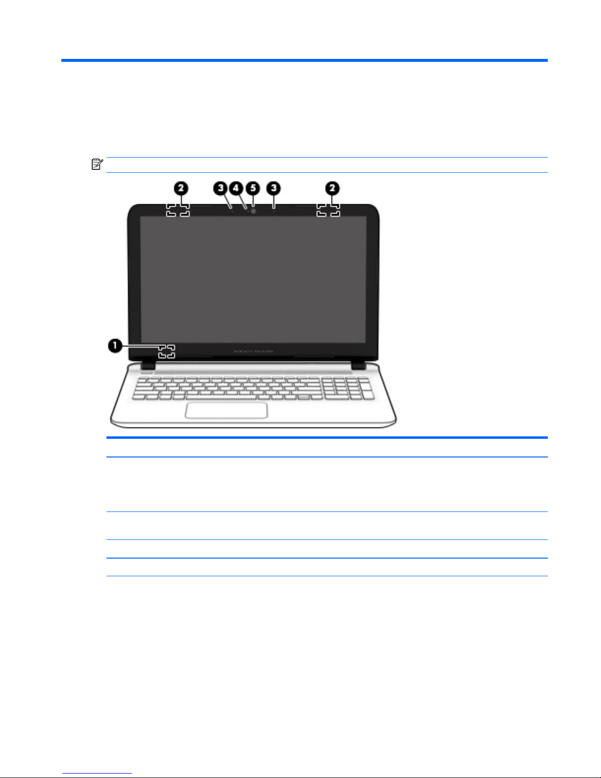
NOTE: Refer to the illustration that most closely matches your computer.
Component Description
(1) Internal display switch Turns off the display and initiates Sleep if the display is closed while
the power is on.
NOTE: The internal display switch is not visible from the outside of
the computer.
(2) WLAN antennas* Send and receive wireless signals to communicate with wireless local
area networks (WLANs).
(3) Internal microphones (2) Record sound.
(4) Webcam light On: The webcam is in use.
(5) Webcam
‒ or –
3D camera (select models only)
Records video and captures photographs. Some models allow you to
video conference and chat online using streaming video.
To use the webcam or 3D camera in Windows 8.1:
▲
From the Start screen, type camera, and then select Camera
from the list of applications.
To use the webcam in Windows 7:
▲
Select Start > All Programs > Communication and Chat >
CyberLink YouCam.
Display 5
Component Description
NOTE: In Windows 8.1, a 3D camera captures 3D images and
displays them on the computer screen. It includes additional
hardware (a 3D camera sensor and a 3D laser projector) plus special
software. To learn more about using a 3D camera, open the Intel
RealSense app Welcome to Intel RealSense. To access the 3D
camera apps, go to the Intel RealSense Technology app.
*The antennas are not visible from the outside of the computer. For optimal transmission, keep the areas immediately around the
antennas free from obstructions. For wireless regulatory notices, see the section of the Regulatory, Safety, and Environmental Notices
that applies to your country or region.
To access this document from Windows 8.1:
From the Start screen, type support, and then select the HP Support Assistant app.
‒ or –
From the Windows desktop, click the question mark icon in the notification area, at the far right of the taskbar.
To access this document from Windows 7, select Start > HP Support Assistant > Next > My computer > User Guides.
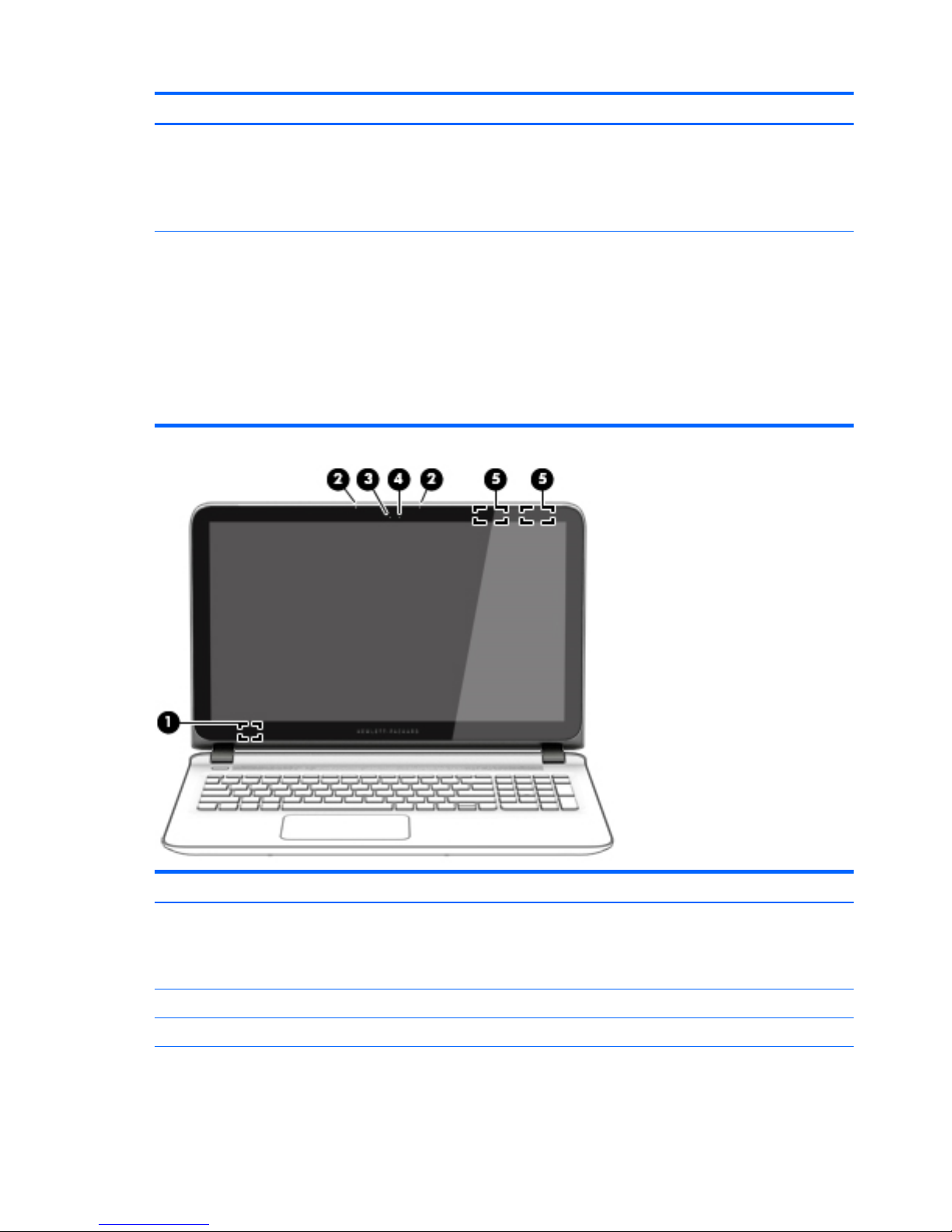
Component Description
(1) Internal display switch Turns off the display and initiates Sleep if the display is closed while
the power is on.
NOTE: The internal display switch is not visible from the outside of
the computer.
(2) Internal microphones (2) Record sound.
(3) Webcam light On: The webcam is in use.
(4) Webcam
‒ or –
Records video and captures photographs. Some models allow you to
video conference and chat online using streaming video.
To use the webcam or 3D camera in Windows 8.1:
6 Chapter 2 External component identification

Component Description
3D camera (select models only)
▲
From the Start screen, type camera, and then select Camera
from the list of applications.
To use the webcam in Windows 7:
▲
Select Start > All Programs > Communication and Chat >
CyberLink YouCam.
NOTE: In Windows 8.1, a 3D camera captures 3D images and
displays them on the computer screen. It includes additional
hardware (a 3D camera sensor and a 3D laser projector) plus special
software. To learn more about using a 3D camera, open the Intel
RealSense app Welcome to Intel RealSense. To access the 3D
camera apps, go to the Intel RealSense Technology app.
(5) WLAN antennas* Send and receive wireless signals to communicate with wireless local
area networks (WLANs).
*The antennas are not visible from the outside of the computer. For optimal transmission, keep the areas immediately around the
antennas free from obstructions. For wireless regulatory notices, see the section of the Regulatory, Safety, and Environmental Notices
that applies to your country or region.
To access this document from Windows 8.1:
From the Start screen, type support, and then select the HP Support Assistant app.
‒ or –
From the Windows desktop, click the question mark icon in the notification area, at the far right of the taskbar.
To access this document from Windows 7, select Start > HP Support Assistant > Next > My computer > User Guides.
Display 7
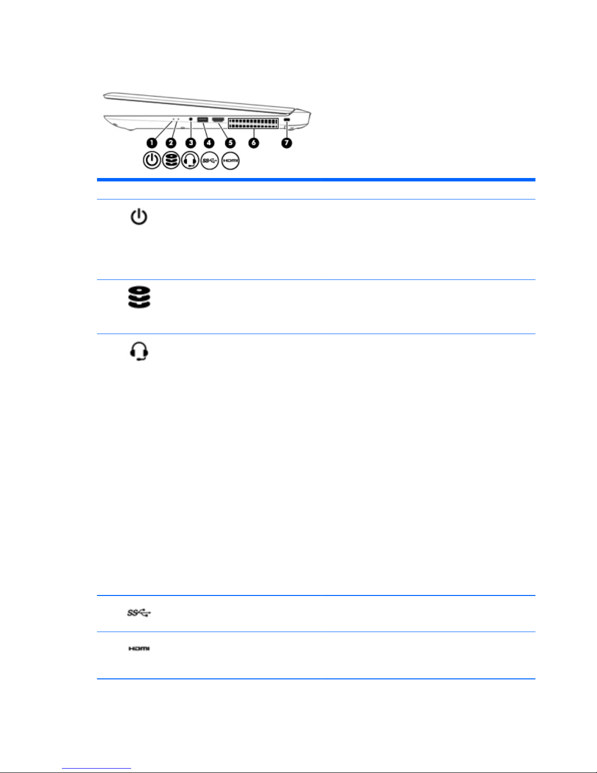
Right side
Component Description
(1)
Power light
●
On: The computer is on.
●
Blinking: The computer is in the Sleep state, a powersaving state. The computer shuts off power to the display
and other components.
●
Off: The computer is off or in Hibernation. Hibernation is a
power-saving state that uses the least amount of power.
(2)
Drive light
●
Blinking white: The hard drive or optical drive is being
accessed.
●
Amber: HP 3D DriveGuard has temporarily parked the hard
drive.
(3)
Audio-out (headphone)/Audio-in (microphone)
jack
Connects optional powered stereo speakers, headphones,
earbuds, a headset, or a television audio cable. Also connects an
optional headset microphone. This jack does not support
optional microphone-only devices.
WARNING! To reduce the risk of personal injury, adjust the
volume before putting on headphones, earbuds, or a headset.
For additional safety information, refer to the Regulatory,
Safety, and Environmental Notices.
To access this document in Windows 8.1:
▲
From the Start screen, type support, and then select the
HP Support Assistant app.
‒ or –
From the Windows desktop, click the question mark icon in
the notification area, at the far right of the taskbar.
To access this document from Windows 7, select Start > HP
Support Assistant > Next > My computer > User Guides.
NOTE: When a device is connected to the jack, the computer
speakers are disabled.
NOTE: Be sure that the device cable has a 4-conductor
connector that supports both audio-out (headphone) and audioin (microphone).
(4)
USB 3.0 port Connects an optional USB device, such as a keyboard, mouse,
external drive, printer, scanner or USB hub.
(5)
HDMI port Connects an optional video or audio device, such as a high-
definition television, any compatible digital or audio
component, or a high-speed High-Definition Multimedia
Interface (HDMI) device.
(6) Vent Enables airflow to cool internal components.
8 Chapter 2 External component identification
NOTE: The computer fan starts up automatically to cool
internal components and prevent overheating. It is normal for
the internal fan to cycle on and off during routine operation.
(7)
Security cable slot Attaches an optional security cable to the computer.
NOTE: The security cable is designed to act as a deterrent, but
it may not prevent the computer from being mishandled or
stolen.
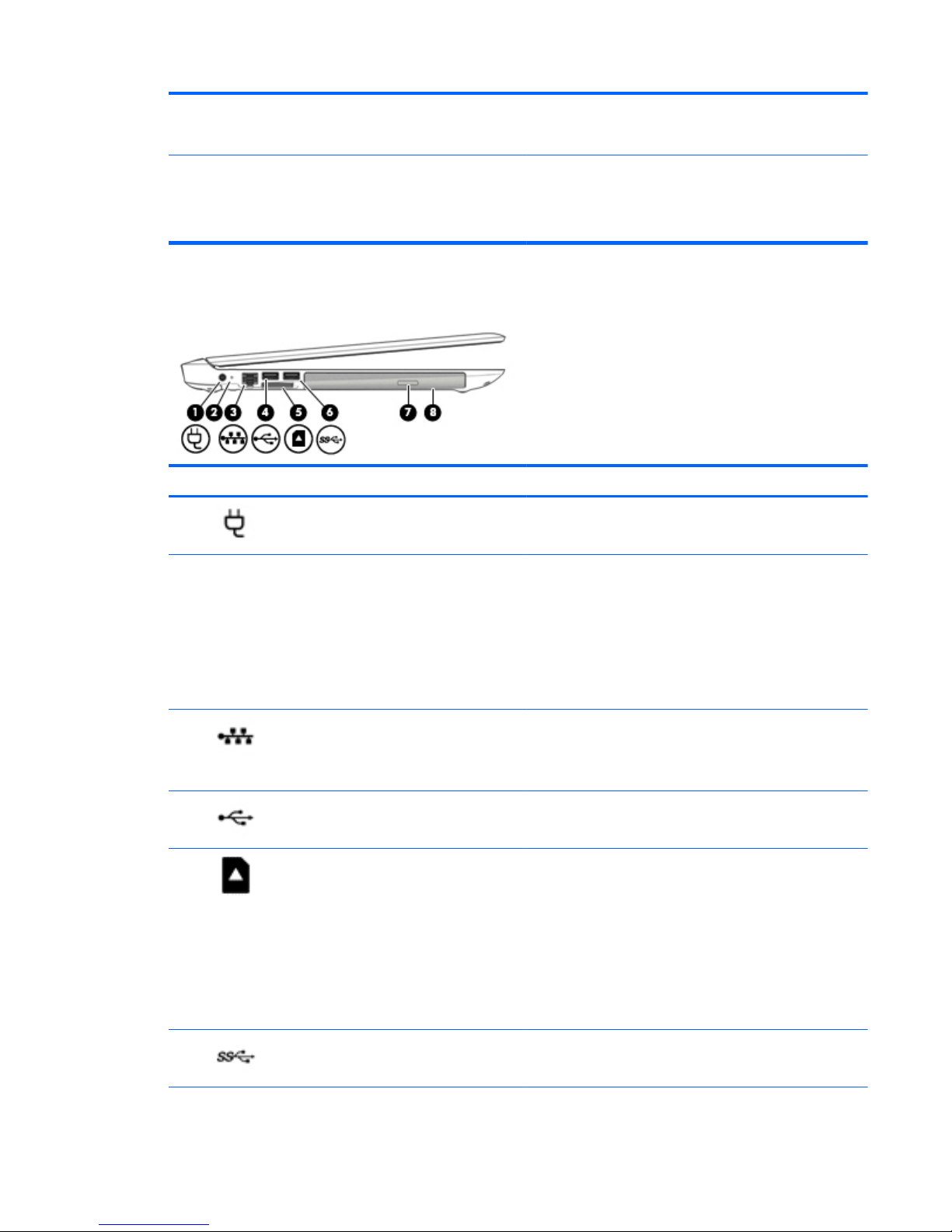
Left side
Component Description
(1)
Power connector Connects an AC adapter.
(2)
AC adapter/battery light
●
White: The AC adapter is connected and the battery is fully
charged.
●
Blinking white: The AC adapter is disconnected and the
battery has reached a low battery level.
●
Amber: The AC adapter is connected and the battery is
charging.
●
Off: The battery is not charging.
(3)
RJ-45 (network) jack/status lights Connects a network cable.
●
White: The network is connected.
●
Amber: Activity is occurring on the network.
(4)
USB 2.0 port Connects an optional USB device, such as a keyboard, mouse,
external drive, printer, scanner or USB hub.
(5)
Memory card reader Reads optional memory cards that enable you to store, manage,
share or access information.
To insert a card:
▲
Hold the card label-side up, with connectors facing the
slot, insert the card into the slot, and then push in on the
card until it is firmly seated.
To remove a card:
▲
Press in on the card it until it pops out.
(6)
USB 3.0 port Connects an optional USB device, such as a keyboard, mouse,
external drive, printer, scanner or USB hub.
Left side 9
Component Description
(7) Optical drive eject button Releases the disc tray.
(8)
Optical drive Depending on your computer model, reads an optical disc or
reads and writes to an optical disc.
NOTE: For disc compatibility information, go to the Help and
Support web page. Follow the web page instructions to select
your computer model. Select Drivers & Downloads, and then
follow the on-screen instructions.
Top
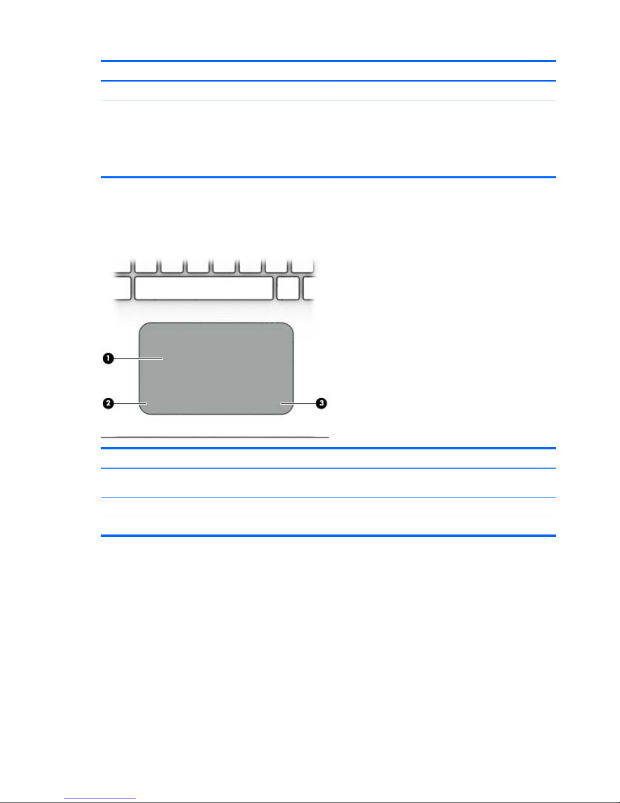
TouchPad
Component Description
(1) TouchPad zone Reads your finger gestures to move the pointer or activate
items on the screen.
(2) Left TouchPad button Functions like the left button on an external mouse.
(3) Right TouchPad button Functions like the right button on an external mouse.
10 Chapter 2 External component identification
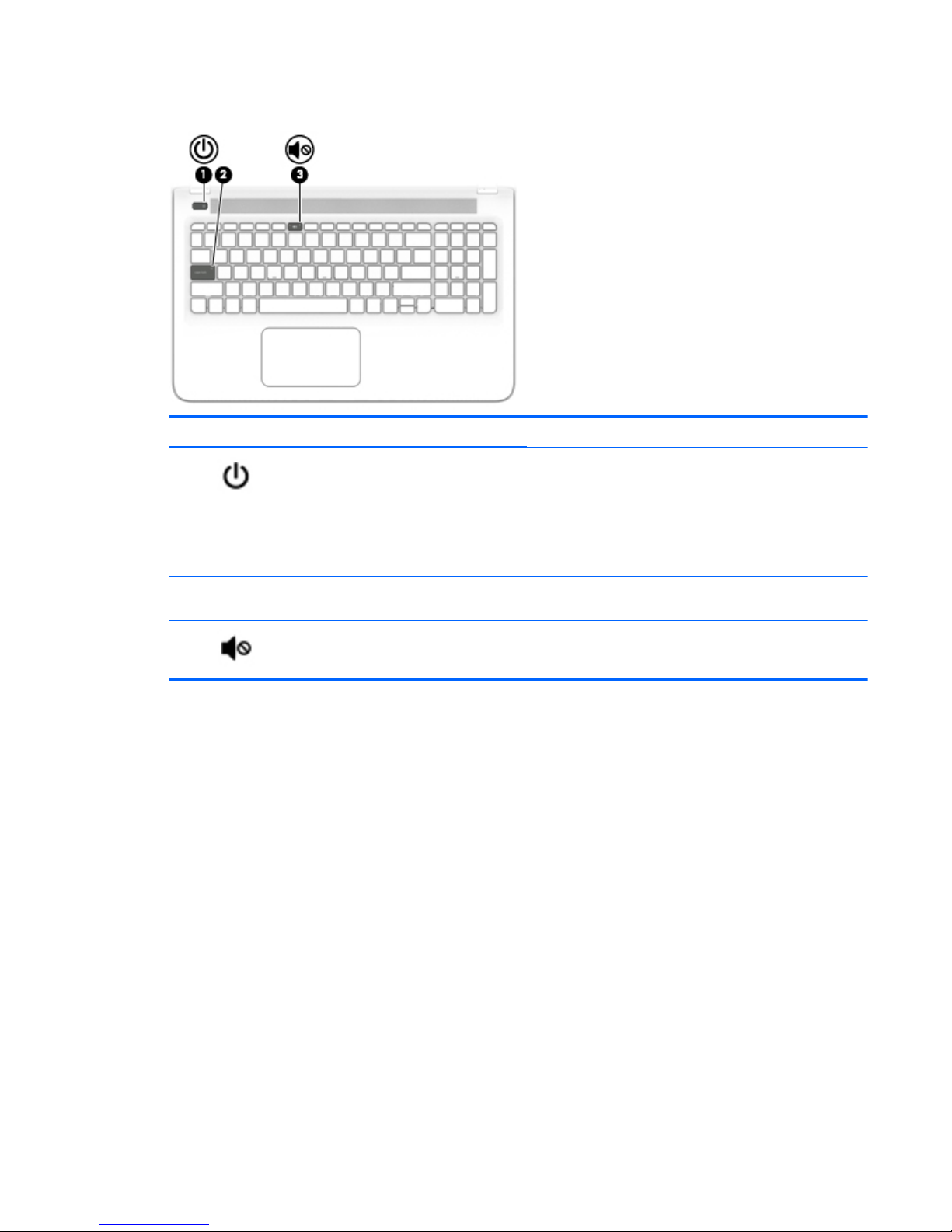
Lights
Component Description
(1)
Power light
●
On: The computer is on.
●
Blinking: The computer is in the Sleep state, a powersaving state. The computer shuts off power to the display
and other unneeded components.
●
Off: The computer is off or in Hibernation. Hibernation is a
power-saving state that uses the least amount of power.
(2) Caps lock light White: Caps lock is on, which switches the keys to all capital
letters.
(3)
Mute light
●
Amber: Computer sound is off.
●
Off: Computer sound is on.
Top 11
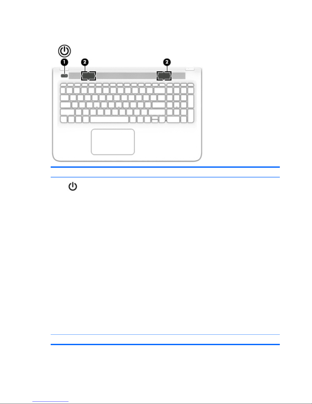
Buttons and speakers
Component Description
(1)
Power button
●
When the computer is off, press the button to turn on the
computer.
●
When the computer is on, press the button briefly to
initiate Sleep.
●
When the computer is in the Sleep state, press the button
briefly to exit Sleep.
●
When the computer is in Hibernation, press the button
briefly to exit Hibernation.
CAUTION: Pressing and holding down the power button will
result in the loss of unsaved information.
If the computer has stopped responding and Windows shutdown
procedures are ineffective, press and hold the power button
down for at least 5 seconds to turn off the computer.
To learn more about your power settings in Windows 8.1, see
your power options.
▲
From the Start screen, type power, select Power and
sleep settings, and then select Power and sleep from the
list of applications.
‒ or –
From the Windows desktop, right-click the Start button,
and then select Power Options.
To learn more about your power settings, select Start > Control
Panel > System and Security > Power Options.
(2) Speakers (2) Produce sound.
12 Chapter 2 External component identification
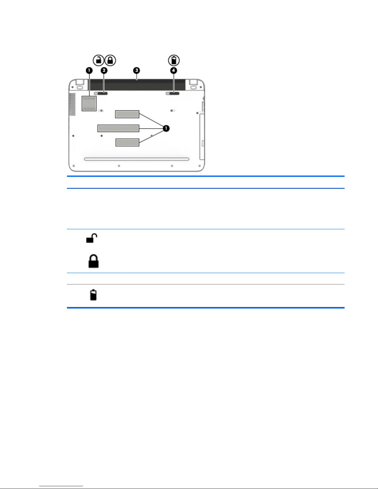
Bottom
Component Description
(1) Vents (4) Enable airflow to cool internal components.
NOTE: The computer fan starts up automatically to cool
internal components and prevent overheating. It is normal
for the internal fan to cycle on and off during routine
operation.
(2)
Battery lock Locks the battery in the battery bay.
(3) Battery bay Holds the battery.
(4)
Battery release latch Releases the battery.
Bottom 13
Labels
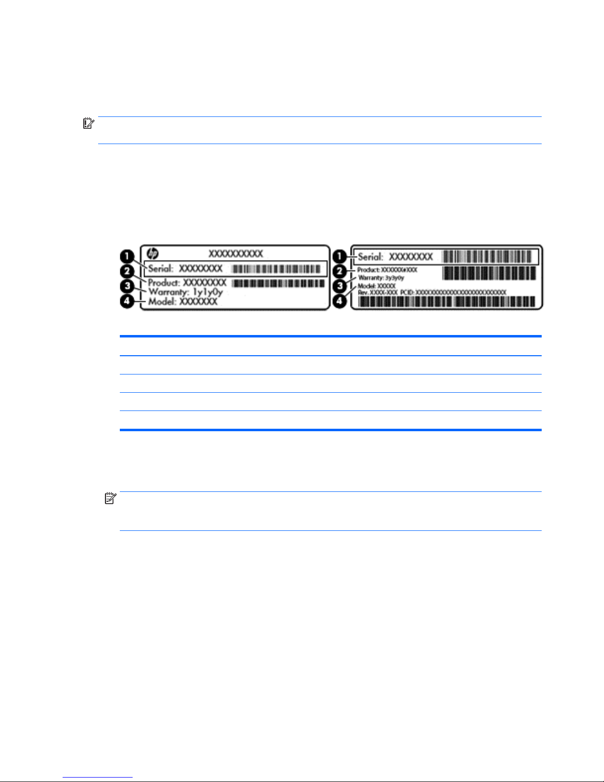
The labels affixed to the computer provide information you may need when you troubleshoot system
problems or travel internationally with the computer.
IMPORTANT: Check the following locations for the labels described in this section: the bottom of the
computer, inside the battery bay, or on the back of the display.
●
Service label—Provides important information to identify your computer. When contacting support,
you will probably be asked for the serial number, and possibly for the product number or the model
number. Locate these numbers before you contact support.
Your service label will resemble one of the examples shown below. Refer to the illustration that most
closely matches the service label on your computer.
Component
(1) Serial number
(2) Product number
(3) Warranty period
(4) Model number (select models only)
●
Microsoft® Certificate of Authenticity label (select models only prior to Windows 8)—Contains the
Windows Product Key. You may need the Product Key to update or troubleshoot the operating system.
HP platforms with Windows 8 or Windows 8.x preinstalled do not have the physical label. Instead a
Digital Product Key is electronically installed.
NOTE: The Digital Product Key is automatically recognized and activated by Microsoft operating
systems when a Windows 8 or Windows 8.x operating system is reinstalled using HP-approved recovery
methods.
●
Regulatory label(s)—Provide(s) regulatory information about the computer.
●
Wireless certification label(s)—Provide(s) information about optional wireless devices and the approval
markings for the countries or regions in which the devices have been approved for use.
14 Chapter 2 External component identification
3 Illustrated parts catalog
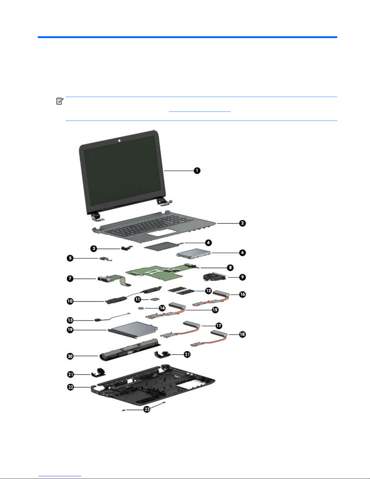
Computer major components
NOTE: HP continually improves and changes product parts. For complete and current information on
supported parts for your computer, go to
http://partsurfer.hp.com, select your country or region, and then
follow the on-screen instructions.
Computer major components 15

Item Component Spare part
number
(1) Display assembly (39.6-cm [15.6-in] HD, touch screen)
NOTE: Touch displays are spared both as entire hinge-ups and at the subcomponent level.
Non-touch displays are only spared at the subcomponent level.
NOTE: For display assembly spare part information, see
Display assembly subcomponents, non-touch
models on page 19 and Display assembly subcomponents, touch models on page 21.
not spared
(2) Top cover/keyboard (includes touchpad)
For use in models without a backlit keyboard:
●
For use in Belgium 809031-A41
●
For use in Bulgaria 809031-261
●
For use in the Czech Republic and Slovakia 809031-FL1
●
For use in Denmark, Finland, and Norway 809031-DH1
●
For use in French Canada 809031-DB1
●
For use in France 809031-051
●
For use in Germany 809031-041
●
For use in Greece 809031-151
●
For use in Hungary 809031-211
●
For use in Israel 809031-BB1
●
For use in Italy 809031-061
●
For use in Japan 809031-291
●
For use in Latin America 809031-161
●
For use in the Netherlands 809031-B31
●
For use in Portugal 809031-131
●
For use in Romania 809031-271
●
For use in Russia 809031-251
●
For use in Saudi Arabia 809031-171
●
For use in Spain 809031-071
●
For use in Slovenia 809031-BA1
●
For use in South Korea 809031-AD1
●
For use in Switzerland 809031-BG1
●
For use in Taiwan 809031-AB1
●
For use in Thailand 809031-281
●
For use in Turkey 809031-141
●
For
use in the United Kingdom 809031-031
●
For use in the United States 809031-001
16 Chapter 3 Illustrated parts catalog

Item Component Spare part
number
For use in models with a backlit keyboard:
●
For use in French Canada 809032-DB1
●
For use in Saudi Arabia 809032-171
●
For use in Turkey 809032-141
●
For use in the United States 809032-001
(3) Optical Drive Cable Kit 811199-001
(4) Touchpad 813987-001
(5) Power button board (includes cable) 809033-001
(6) Hard drive (does not include bracket):
NOTE: The hard drive bracket and connector are available using spare part number 809296-001.
2-TB, 5400-rpm, 2.5-inch 801808-005
1-TB, 5400-rpm, 2.5-inch, hybrid 8 GB SSD 731999-005
1-TB, 5400-rpm, 2.5-inch 778192-005
750 GB, 5400 rpm hard drive, 2.5 inch 778190-005
500-GB, 5400-rpm, 7 mm 778186-005
(7) USB board (includes cable) 809409-001
(8) System board (includes replacement thermal materials)
All system boards use the following part numbers:
xxxxxx-001: Without the Windows operating system
xxxxxx-501: Windows 8.1 Standard
xxxxxx-601: Windows 8.1 Professional
For use in models with 2 GB of discrete graphics memory:
●
AMD A10-8700P processor 809408-xxx
●
AMD A8-7410 processor 809407-xxx
●
AMD A6-6310 processor 809339-xxx
For use in models with UMA graphics memory:
●
AMD A10-8700P processor 809338-xxx
●
AMD A8-7410 processor 809337-xxx
●
AMD A6-6310 processor 809336-xxx
●
AMD A4-6210 processor 809335-xxx
(9) Fan 806747-001
(10) Speakers (includes left and right speakers and cable) 809037-001
(11) WLAN module
Intel Dual Band Wireless-AC 7265 802.11 ac 2x2 WiFi + BT 4.0 Combo Adapter (non vPRO) 784644-005
Computer major components 17

Item Component Spare part
number
Realtek RTL8188EE 802.11b/g/n 1x1 Wi-Fi Adapter 792609-005
Realtek RTL8723BE 802.11b/g/n 1x1 Wi-Fi + BT4.0 Combo Adapter 792610-005
(12) Memory module (DDR3L-1600)
8-GB 693374-005
4 GB 691740-005
2 GB 691739-005
(13) Power connector cable 806746-001
(14) RTC battery 811080-001
Heat sink assembly (includes replacement thermal materials)
(15) For use in models with discrete graphics in the Carrizo chipset 809105-001
(16) For use in models with discrete graphics in the Carrizo-L and Beema chipsets 806760-001
(17) For use in models with UMA graphics in the Carrizo chipset 809104-001
(18) For use in models with UMA graphics in the Carrizo-L and Beema chipsets 806759-001
(19) DVD+/-RW Double-Layer SuperMulti Drive
For use in silver models 809328-001
For use in white models 809329-001
For use in red models 809330-001
For use in blue models 809331-001
For use in pink models 809332-001
For use in purple models 809333-001
For use in black models 812889-001
Blu-ray Disc R/RW with SuperMulti Drive
For use in silver models 809334-001
(20) Battery (4-cell, 41-Whr, 2.8-Ah Li-ion) 800049-001
(21) Base enclosure hinge caps (left and right) 809034-001
(22) Bottom cover
For use in purple models 809026-001
For use in red models 809023-001
For use in white models 809022-001
For use in blue models 809024-001
For use in silver models 809021-001
For use in pink models 809025-001
For use in black models 809345-001
(23) Rubber screw covers 809035-001
18 Chapter 3 Illustrated parts catalog
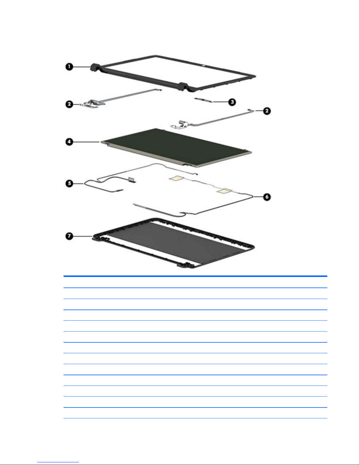
Display assembly subcomponents, non-touch models
Item Component Spare part number
(1) Display bezel (includes Mylar screw covers) 809027-001
(2) Hinges (left and right, includes Mylar screw covers) 809030-001
(3) Webcam/microphone module 806758-001
(4) Raw display panel (39.6-cm [15.6-in]; includes Mylar screw covers)
BrightView, HD, flat 809371-001
AntiGlare, FHD, slim 809372-001
TOP (Touch On Panel) 813109-001
(5) Display cable (includes Mylar screw covers)
For use in non-touch displays 809028-001
For use in TOP (Touch On Panel) displays 809342-001
(6) Antennas (includes wireless antenna cables and transceivers; includes Mylar screw covers) 809008-001
(7) Display enclosure (includes Mylar screw covers):
Display assembly subcomponents, non-touch models 19

Item Component Spare part number
For use in models with non-touch displays:
●
Red models 809011-001
●
White models 809010-001
●
Silver models 809009-001
●
Blue models 809012-001
●
Purple models 809014-001
●
Pink models 809013-001
●
Black models 809343-001
For use in TOP (touch on panel) models:
●
Black models 818657-001
●
Red models 818653-001
●
White models 817836-001
●
Silver models 817835-001
●
Blue models 818654-001
●
Purple models 818656-001
●
Pink models 818655-001
20 Chapter 3 Illustrated parts catalog
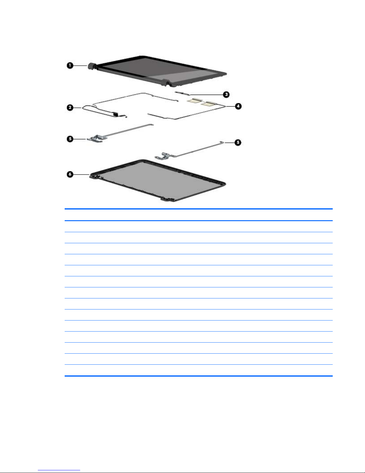
Display assembly subcomponents, touch models
Item Component Spare part number
(1) Display bezel and panel 809341-001
(2) Display cable (includes Mylar screw covers)
For use in touch displays 811222-001
(3) Webcam/microphone module 810961-001
(4) Antennas (includes wireless antenna cables and transceivers) 811201-001
(5) Hinges (left and right) 813345-001
(6) Display enclosure:
For use in silver models 809015-001
For use in white models 809016-001
For use in red models 809017-001
For use in blue models 809018-001
For use in pink models 809019-001
For use in purple models 809020-001
For use in black models 809344-001
Display assembly subcomponents, touch models 21

Miscellaneous parts
Component Spare part number
HP Smart AC adapter:
65-W non-PFC EM HP Smart AC adapter (for use in the People’s Republic of China and India only) 714657-001
AC adapter, 65-W, non-PFC, 4.5 mm 710412-001
45-W non-PFC, non-slim HP Smart AC adapter (for use in all countries and regions except for the
People’s Republic of China and India)
741727-001
Power cord (3-pin, black, 1.0-m):
For use in Australia 755530-011
For use in Denmark 755530-081
For use in Europe, the Middle East, and Africa 755530-021
For use in India 755530-D61
For use in Israel 755530-BB1
For use in Italy 755530-061
For use in Japan 755530-291
For use in North America 755530-001
For use in the People's Republic of China 755530-AA1
For use in South Korea 755530-AD1
For use in Switzerland 755530-111
For use in Taiwan 755530-AB1
For use in Thailand 755530-201
For use in the United Kingdom and Singapore 755530-031
Rubber Kit (includes front and rear feet) 809035-001
Screw Kit 809036-001
HDMI to VGA adapter 701943-001
22 Chapter 3 Illustrated parts catalog
 Loading...