

Page 1
Guide to the Printer
1
Installing Options
2
Connecting the Printer
3
Configuration
4
Paper and Other Media
5
Replacing Consumables
6
Adjusting the Printer
7
Troubleshooting
8
Hardware Guide
Removing Misfed Paper
9
Appendix
10
Read this manual carefully before you use this machine and keep it handy for future reference. For safe and correct use, be sure to read the
Safety Information before using the machine.
Page 2

Trademarks
Microsoft, Windows and Windows NT are registered trademarks of Microsoft
Corporation in the United States and/or other countries.
Adobe
istered trademarks of Adobe Systems Incorporated.
PCL
Apple, AppleTalk, EtherTalk, Macintosh, Mac OS, and True Type are trademarks of Apple Computer, Inc., registered in the U.S. and other countries.
IPS-PRINT Printer Language Emulation Copyright© 1999-2000 Oak Technology, Inc., All rights reserved.
NetWare is a registered trademark of Novell, Inc.
Other product names used herein are for identification purposes only and might
be trademarks of their respective companies. We disclaim any and all rights to
those marks.
The proper names of the Windows operating systems are as follows:
•Microsoft
•Microsoft
•Microsoft
• The product names of Windows
• The product names of Windows
• The product names of Windows Server
• The product names of Windows NT
®
, PostScript®, Acrobat®, PageMaker® and Adobe Type Manager are reg-
®
is a registered trademark of Hewlett-Packard Company.
®
Windows® 95 operating system
®
Windows® 98 operating system
®
Windows® Millennium Edition (Windows Me)
®
2000 are as follows:
®
XP are as follows:
TM
2003 are as follows:
®
4.0 are as follows:
Microsoft
Microsoft
Microsoft
Microsoft
Microsoft
Microsoft
Microsoft
Microsoft
Microsoft
Microsoft
®
Windows® 2000 Advanced Server
®
Windows® 2000 Server
®
Windows® 2000 Professional
®
Windows® XP Professional
®
Windows® XP Home Edition
®
Windows ServerTM 2003 Standard Edition
®
Windows ServerTM 2003 Enterprise Edition
®
Windows ServerTM 2003 Web Edition
®
Windows NT® Server 4.0
®
Windows NT® Workstation 4.0
i
Page 3
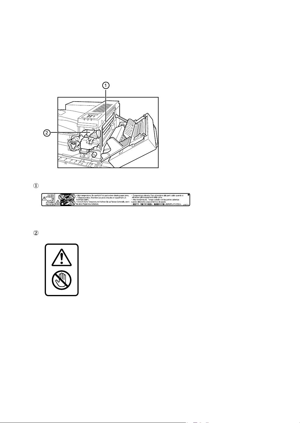
Positions of RWARNING and RCAUTION
labels
This machine has labels for RWARNING and RCAUTION at the positions
shown below. For safety, please follow the instructions and handle the machine
as indicated.
AQV254S
High temperature parts. Turn off the main power and be careful when replacing
fusing unit/removing misfed paper.
The surface of the fusing unit becomes very hot. Do not touch parts labelled “R”
(indicating a hot surface). Touching these parts will result in burns.
ii
Page 4

Manuals for This Printer
For particular functions, see the relevant parts of the manual.
❖ Safety Information
Provides information on safe usage of this machine.
To avoid injury and prevent damage to the machine, be sure to read this.
❖ Quick Installation Guide
Contains procedures for removing the printer from its box, connecting it to a
computer, and installing its driver.
❖ Hardware Guide
Contains information about paper and procedures such as installing options,
replacing consumables, responding to error messages, and resolving jams.
❖ Software Guide
Contain procedures for using this machine in a network environment, utilizing the software, and using security functions.
iii
Page 5

How to Read This Manual
Symbols
This manual uses the following symbols:
Indicates important safety notes.
Ignoring these notes could result in serious injury or death. Be sure to read these
notes.
They can be found in the "Safety Information".
Indicates important safety notes.
Ignoring these notes could result in moderate or minor injury, or damage to the
machine or to property. Be sure to read these notes.
They can be found in the "Safety Information".
Indicates points to pay attention to when using the machine, and explanations
of likely causes of paper misfeeds, damage to originals, or loss of data. Be sure
to read these explanations.
Indicates supplementary explanations of the machine’s functions, and instructions on resolving user errors.
This symbol is located at the end of sections. It indicates where you can find further relevant information.
[ ]
Indicates the names of keys that appear on the machine’s display panel.
{ }
Indicates the names of keys on the machine’s control panel.
iv
Page 6
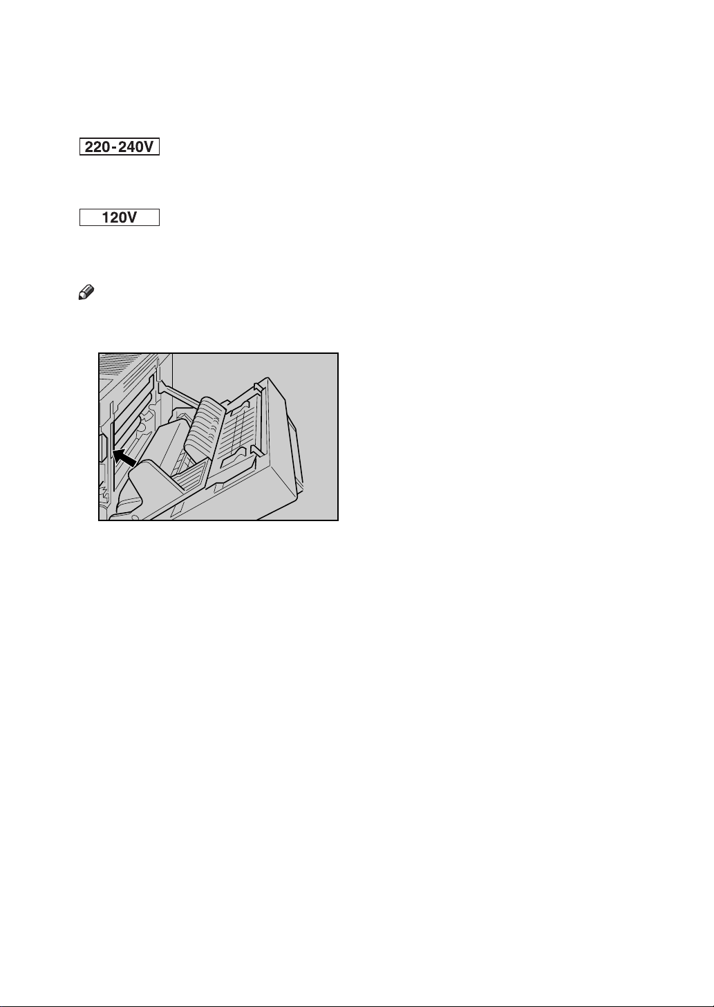
Description for the Specified Model
In this manual, the following items explain about the printer for the specified
models:
This explains about the 220–240 V model printer.
Read if you purchase this model.
This explains about the 120 V model printer.
Read if you purchase this model.
Note
❒ You can identify the printer's model by checking the label on its inside as
shown.
AQV745S
v
Page 7

Installing the Operating Instructions
The CD-ROM “Manuals” provided with the printer contains an HTML Operating Instructions Manual in HTML version. Follow this instructions to install it.
Important
❒ System Requirements :
• Windows 95/98/Me, Windows 2000/XP, Windows Server 2003 or Windows NT4.0.
• 800 × 600 or higher monitor resolution.
❒ Web Browsers :
• Microsoft Internet Explorer 5.5 SP2 or higher
• Firefox 1.0 or higher
A Quit all applications currently running.
B Insert the CD-ROM “Manuals” into the CD-ROM drive.
The installer starts.
Auto Run may not work under certain operating system setting. If this is the
case, launch “Setup.exe” on the CD-ROM root directory.
C Select an interface language, and then click [OK].
D Click [Install manuals].
E Follow the instructions on the screen to complete the installation.
F Click [Finish] when the installation is completed.
G Click [Exit].
Note
❒ Auto Run may not work under certain operating system setting. If this is
the case, copy all data on the CD-ROM root directory to your hard disk
drive, and then launch “Setup.exe” to start the installation.
❒ To uninstall the Operating Instructions Manual, select [Programs] in the
[Start] menu, select your printer driver, and then click [uninstall]. You can
uninstall each Manual Guide separately.
❒ If you are using an incompatible Web browser and the simpler version of
the Operating Instructions Manual does not display correctly, open the
folder “MANUALLANG (language)\(manual name)unv” on the CDROM “Manuals”, and then double-click on “index.htm”.
vi
Page 8

TABLE OF CONTENTS
Trademarks..............................................................................................................i
Positions of RWARNING and RCAUTION labels ..............................................ii
Manuals for This Printer.......................................................................................iii
How to Read This Manual ....................................................................................iv
Symbols .................................................................................................................... iv
Description for the Specified Model.....................................................................v
Installing the Operating Instructions ..................................................................vi
1. Guide to the Printer
Exterior: Front View...............................................................................................1
Exterior: Rear View ................................................................................................2
Inside.......................................................................................................................3
Control Panel..........................................................................................................4
2. Installing Options
Available Options...................................................................................................5
Option List ..................................................................................................................5
Option Installation Flow Chart ....................................................................................6
Installing Options........................................................................................................7
Caution when re-installing the controller board..........................................................9
Attaching Paper Feed Unit PB 3020...................................................................10
Attaching User Account Enhance Unit Type E .................................................16
Attaching Printer Hard Disk Drive Type 8100....................................................20
Attaching Memory Unit Type D 128MB, Memory Unit Type E 256MB (SDRAM
Module) ...............................................................................................................27
Attaching IEEE 802.11b Interface Unit ...............................................................32
Attaching IEEE 1284 Interface Board Type A....................................................36
Attaching Gigabit Ethernet Board ......................................................................38
Attaching VM Card Type D..................................................................................41
Attaching Data Storage Card Type A .................................................................43
3. Connecting the Printer
Network Connection ............................................................................................45
Reading the LED Lamps ..........................................................................................47
USB Connection...................................................................................................48
Parallel Connection .............................................................................................49
4. Configuration
Ethernet Configuration........................................................................................51
Using DHCP - Detecting the Network Address Automatically..................................54
Making Network Settings for Using Netware............................................................55
IEEE 802.11b (Wireless LAN) Configuration .....................................................57
vii
Page 9

5. Paper and Other Media
Paper and Other Media Supported by This Printer...........................................63
Paper Recommendations....................................................................................67
Loading Paper..........................................................................................................67
Storing Paper ...........................................................................................................67
Types of Paper and Other Media.............................................................................68
Paper not supported by this printer..........................................................................69
Print Area .................................................................................................................70
Loading Paper......................................................................................................71
Loading Paper in Tray 1, Tray 2, and the Optional Paper Feed Unit .......................71
Loading Paper in the Optional Large Capacity Tray ................................................74
Setting a Paper Size by Using the Control Panel.....................................................76
Specifying a Paper Type for Tray 1/2 and the Optional Paper Feed Unit ................ 78
Loading Paper in the Bypass Tray ...........................................................................79
Switching between Paper Trays............................................................................... 85
6. Replacing Consumables
Replacing the Toner Cartridge ...........................................................................87
Adding Staples.....................................................................................................92
7. Adjusting the Printer
Adjusting the Image Density...............................................................................95
Adjusting Tray Registration................................................................................96
8. Troubleshooting
Error & Status Messages on the Control Panel ................................................99
Printer Does Not Print .......................................................................................101
Checking the port connection.................................................................................102
Other Printing Problems ...................................................................................104
Additional Troubleshooting..............................................................................109
Removing Jammed Staples ..............................................................................111
Removing Punch Waste ....................................................................................114
9. Removing Misfed Paper
Removing Misfed Paper ....................................................................................117
When “Remove Misfeed A,Y:Paper Tray” Appears ...............................................118
When “Remove Misfeed B,C,D:Inter.Path” Appears.............................................. 121
When “Remove Misfeed R:Finisher” Appears........................................................124
When “Remove Misfeed U:LCT” Appears..............................................................127
When “Remove Misfeed Z:Duplex Unit” Appears ..................................................129
viii
Page 10

10.Appendix
Moving and Transporting the Printer............................................................... 131
Moving the Printer ..................................................................................................132
Consumables .....................................................................................................133
Toner Cartridge ......................................................................................................133
Maintenance Kit .....................................................................................................133
Specifications.....................................................................................................134
Mainframe ..............................................................................................................134
Options...................................................................................................................137
INDEX....................................................................................................... 143
ix
Page 11

x
Page 12
1. Guide to the Printer
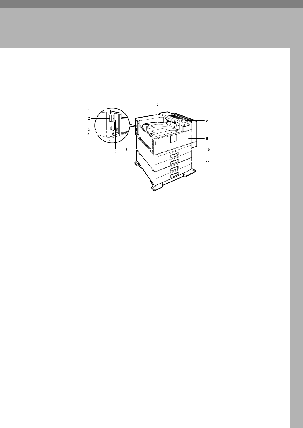
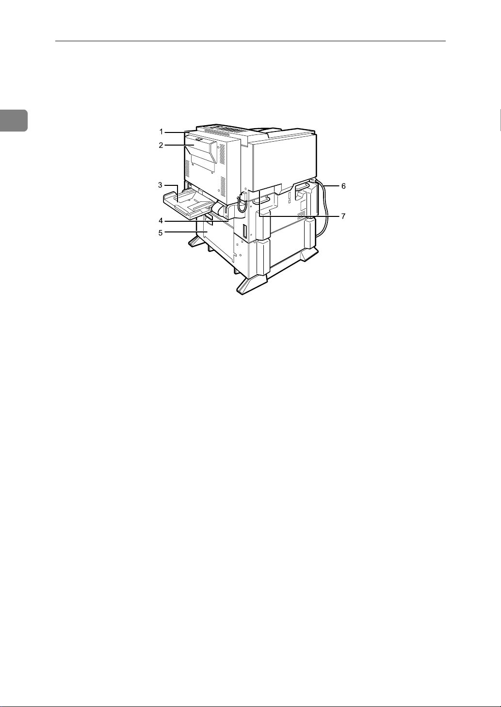
Exterior: Front View
1. Controller Board
Remove this board when installing the
hard disk unit, SDRAM modules, or User
Account Enhance unit.
2. Optional board slots
Remove the cover when installing the optional board.
3. USB port
Use a USB cable to connect the printer to
the host computer.
4. Ethernet Port
Use a network interface cable to connect
the printer to the network.
5. Expansion card slot
Insert an optional unit into a slot.
6. Power Switch
Use this switch to turn the printer power
on and off.
AQV002S
7. Output Tray
Printed output is stacked here with the
print side face down.
8. Control Panel
Contains keys for printing operation and
a panel display that shows the printer
status.
9. Front Cover
Open this cover if you replace some parts
or if a paper misfeed occurs.
10. Paper Tray
Holds up to 550 sheets of plain paper per
tray and 1100 sheets in total. (80 g/m
2
, 20 lb.)
11. Paper Feed Unit PB 3020 (Op-
tion)
Holds up to 550 sheets of plain paper per
tray and 1100 sheets in total. (80 g/m
2
, 20 lb.)
1
Page 13
1
Guide to the Printer
Exterior: Rear View
AQV031S
1. Duplex Unit
Allows you to print onto both sides of the
paper.
2. Duplex Unit Right Cover
Open this cover when accessing the inside of the printer.
3. Bypass Tray
Holds up to 50 sheets of plain paper. (80
2
, 20 lb.)
g/m
4. Upper Vertical Paper Feed Cover
Open this cover when accessing the inside of the printer.
If you install the optional Large Capacity
Tray RT45, remove this cover.
5. Lower Vertical Paper Feed Cover
Open this cover when accessing the inside of the printer.
6. Power Cord
Plug this cord into a wall outlet.
7. Ventilator
Helps to keep components inside the
printer from overheating.
2
Page 14
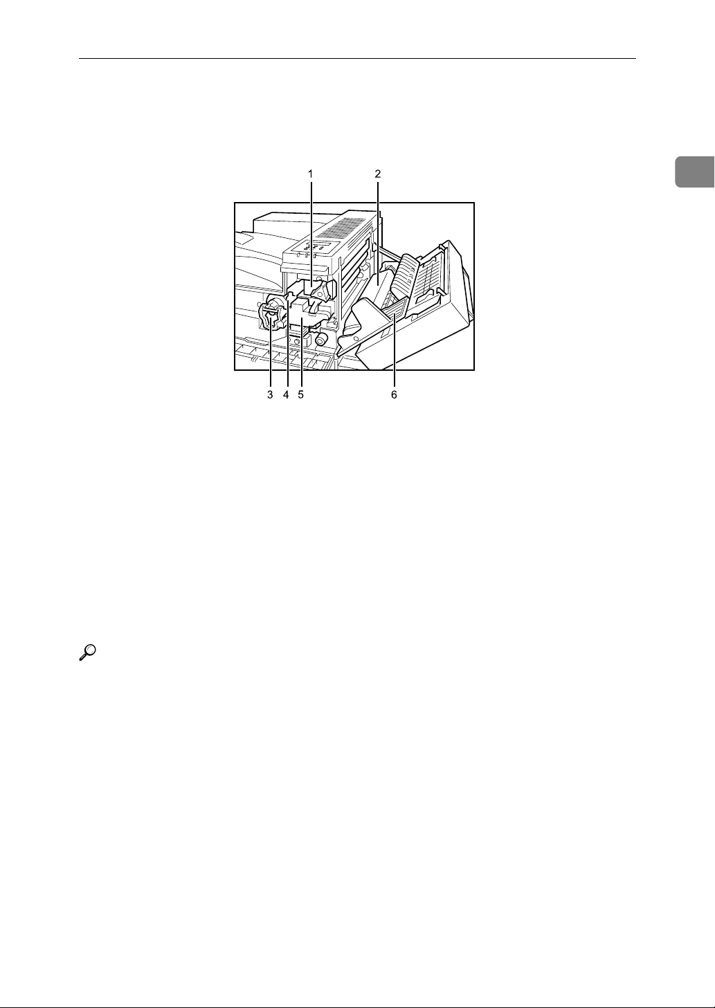
Inside
Inside
1
AQV005S
1. Fusing Unit
When “Replace Maintenance Kit” appears on the panel display, replace this
unit.
2. Transfer Unit
When “Replace Maintenance Kit” appears on the panel display, replace this
unit.
3. Toner Lock Handle
Turn up the lever when replacing the
toner.
Reference
For details about the messages which appear on the screen to prompt you to
replace the units, see p.99 “Error & Status Messages on the Control Panel”.
4. Toner Holder
Slide this out when replacing the toner.
5. Development Unit
When “Replace Maintenance Kit” appears on the panel display, replace this
unit.
6. Right Cover
Open this cover when accessing the inside of the printer.
3
Page 15
1
Guide to the Printer
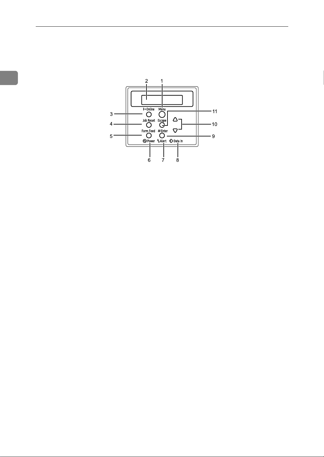
Control Panel
AQV250S
1. {Menu} Key
Press this key to make and check the current printer settings.
2. Panel Display
Shows the current status of the printer
and error messages.
3. {Online} Key
Press this key to switch the printer between online and offline.
4. {Job Reset} Key
When the printer is online, press this key
to cancel any ongoing print job.
See “Canceling a Print job”, Softtware
Guide.
5. {Form Feed} Key
If the printer is offline, press this key to
print all the data left in the printer's input
buffer.
This does not work if the printer is online.
6. Power Indicator
Is on when the printer power is on.
Is off when the power is off or when the
printer is in Energy Saver mode.
7. Alert Indicator
Blinks or lights up whenever any printer
error occurs. A message describing the
cause of the error also appears on the
panel display.
8. Data In Indicator
Blinks while the printer is receiving data
from a computer.
Is on if there is data to be printed.
9. {q Enter} Key
Press this key to execute menu items selected on the panel display.
Press this key to clear some errors.
10. {U} {T} Keys
Use these keys to increase or decrease
values on the panel display when making
settings.
11. {Escape} Key
Press this key to return to the previous
condition on the panel display.
4
Page 16
2. Installing Options
R
Available Options
This section describes how to install options.
By installing options, you can improve the printer performance and have an expanded variety of features to use. For the specifications of each option, see p.134
“Specifications”.
CAUTION:
• Before installing options, the machine should be turned off and unplugged
for at least an hour. Components inside the machine become very hot, and
can cause a burn if touched.
• Before moving the machine, unplug the power cable from the outlet. If the
cable is unplugged abruptly, it could become damaged. Damaged plugs or
cables can cause an electrical or fire hazard.
• When lifting the machine, use the grips on both sides. The machine could
break or cause an injury if dropped.
Important
❒ The voltage rating of the connector for options is 24 V DC or less.
Option List
The following is a list of options for this printer.
• Finisher SR 3040
• Paper Feed Unit PB 3020
• Large Capacity Tray RT45
• Bridge Unit Type 2045
• Punch Kit Type 1045
• Memory Unit Type D 128MB
• Memory Unit Type E 256MB
• User Account Enhance Unit Type E
• IEEE 802.11b Interface Unit
• IEEE 1284 Interface Board Type A
• Gigabit Ethernet Board Type A
• Printer Hard Disk Drive Type 8100
•VM Card Type D
• Data Storage Card Type A
*1
If you want to install the unit, contact your sales or service representative.
*1
*1
*1
*1
*1
5
Page 17

Installing Options
Option Installation Flow Chart
Installing multiple options in the following order is recommended:
A Attatch the paper feed unit (Paper Feed Unit PB 3020).
Attach the paper feed unit to the bottom of the printer.
2
B Take out the controller board from the printer.
C Install User Account Enhance Unit (User Account Enhance Unit Type E).
Install the module to the User Account Enhance Unit slot of the controller
board.
D Remove all SDRAM modules before installing the hard disk drive.
E Install the hard disk drive (Printer Hard Disk Drive Type 8100).
Install the hard disk drive to the controller board.
F Install the SDRAM module (Memory Unit Type D 128MB, Memory Unit
Type E 256MB).
Install the module to the SDRAM module slot on the controller board.
There are two types of memory unit: 128 MB and 256 MB.
G Install IEEE 1284 interface board, IEEE 802.11b interface unit, or Gigabit
Ethernet board.
Install one of these options into the vacant expansion slot (on the left) of the
controller board.
The followings can be installed:
• IEEE 1284 Interface Board Type A
• IEEE 802.11b Interface Unit
• Gigabit Ethernet Board Type A
Do not install more than one option. These options do not function simultaneously.
H Install the VM card (VM Card Type D) or the data storage card (Data Stor-
age Card Type A).
Insert these units into the SD card slot on the controller board.
6
Page 18
Installing Options
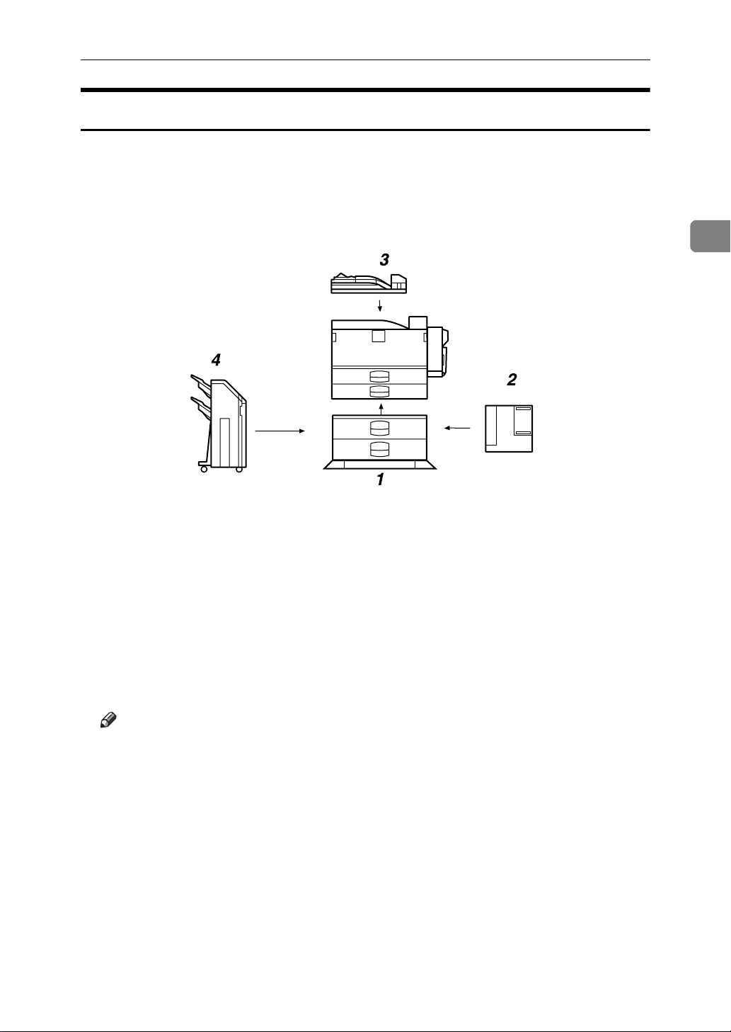
Install options in the positions shown in the illustration.
❖ Exterior
Available Options
2
AQV017S
1. Paper Feed Unit PB 3020
2. Large Capacity Tray RT45
Holds up to 1500 sheets of plain paper. (80 g/m
If you want to install the Large Capacity Tray RT45, contact your sales or
service representative.
Note
2
, 20 lb.)
3. Bridge Unit Type 2045
This unit is necessary when using the
Finisher.
If you want to install the Bridge Unit
Type 2045, contact your sales or service representative.
4. Finisher SR 3040
If you want to install the Finisher SR
3040, contact your sales or service representative.
❒ Bridge Unit Type 2045 is required when you install Finisher SR 3040.
❒ To use the punch function with the Finisher SR 3040, Punch Kit Type 1045
is required.
7
Page 19
2
Installing Options
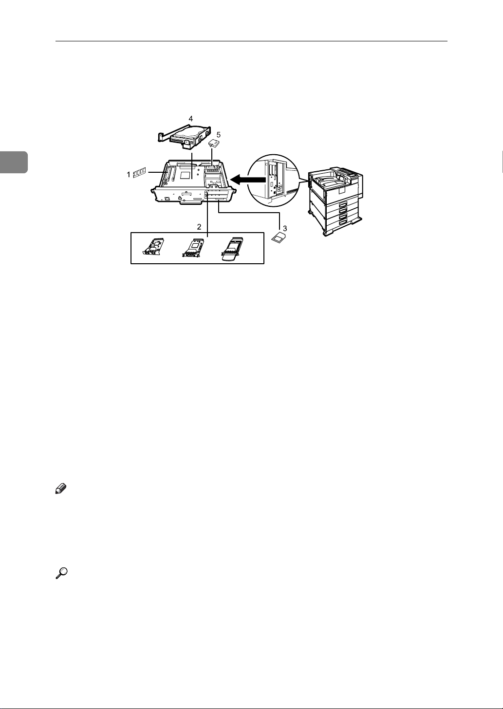
❖ Interior
1.
Memory Unit Type D 128MB/Memo-
ry Unit Type E 256MB (SDRAM module)
Install 128 MB or 256 MB SDRAM
module into the controller board slot.
See p.27 “Attaching Memory Unit
Type D 128MB, Memory Unit Type E
256MB (SDRAM Module)”.
2. Optional boards
See p.32 “Attaching IEEE 802.11b Interface Unit”.
See p.36 “Attaching IEEE 1284 Interface Board Type A”.
See p.38 “Attaching Gigabit Ethernet
Board”.
AQV019S
3. Optional units
See p.41 “Attaching VM Card Type
D”.
See p.43 “Attaching Data Storage
Card Type A”.
4. Printer Hard Disk Drive Type 8100
See p.20 “Attaching Printer Hard Disk
Drive Type 8100”.
5. User Account Enhance Unit Type E
See p.16 “Attaching User Account Enhance Unit Type E”.
Note
❒ You cannot install following options at the same time:
• IEEE 802.11b Interface Unit
• IEEE 1284 Interface Board Type A
• Gigabit Ethernet Board Type A
Reference
For the specifications of each option, see p.134 “Specifications”.
8
Page 20

Available Options
Caution when re-installing the controller board
This section describes handling the controller board when installing options.
If you slide out the controller board to install units, carefully read the instruction
to re-install the controller board.
Important
❒ The following may occur if the controller board is not properly installed:
• all control panel indicators are lit.
• no control panel indicators is lit.
• the error message appears on the display.
2
9
Page 21
2
R
Installing Options
Attaching Paper Feed Unit PB 3020
When installing multiple options, install the paper feed unit first.
CAUTION:
• Before moving the machine, unplug the power cord from the outlet. If the
cord is unplugged abruptly, it could become damaged. Damaged plugs or
cords can cause an electrical or fire hazard.
• When lifting the machine, use the grips on both sides. The machine could
break or cause an injury if dropped.
• When lifting the paper feed unit, hold the bottom of it, and then lift it slowly.
Lifting it carelessly or dropping it may cause an injury.
Important
❒
Before using the new paper feed unit, you must make settings in the printer driver.
❒ Check the printer nameplate to confirm the model code.
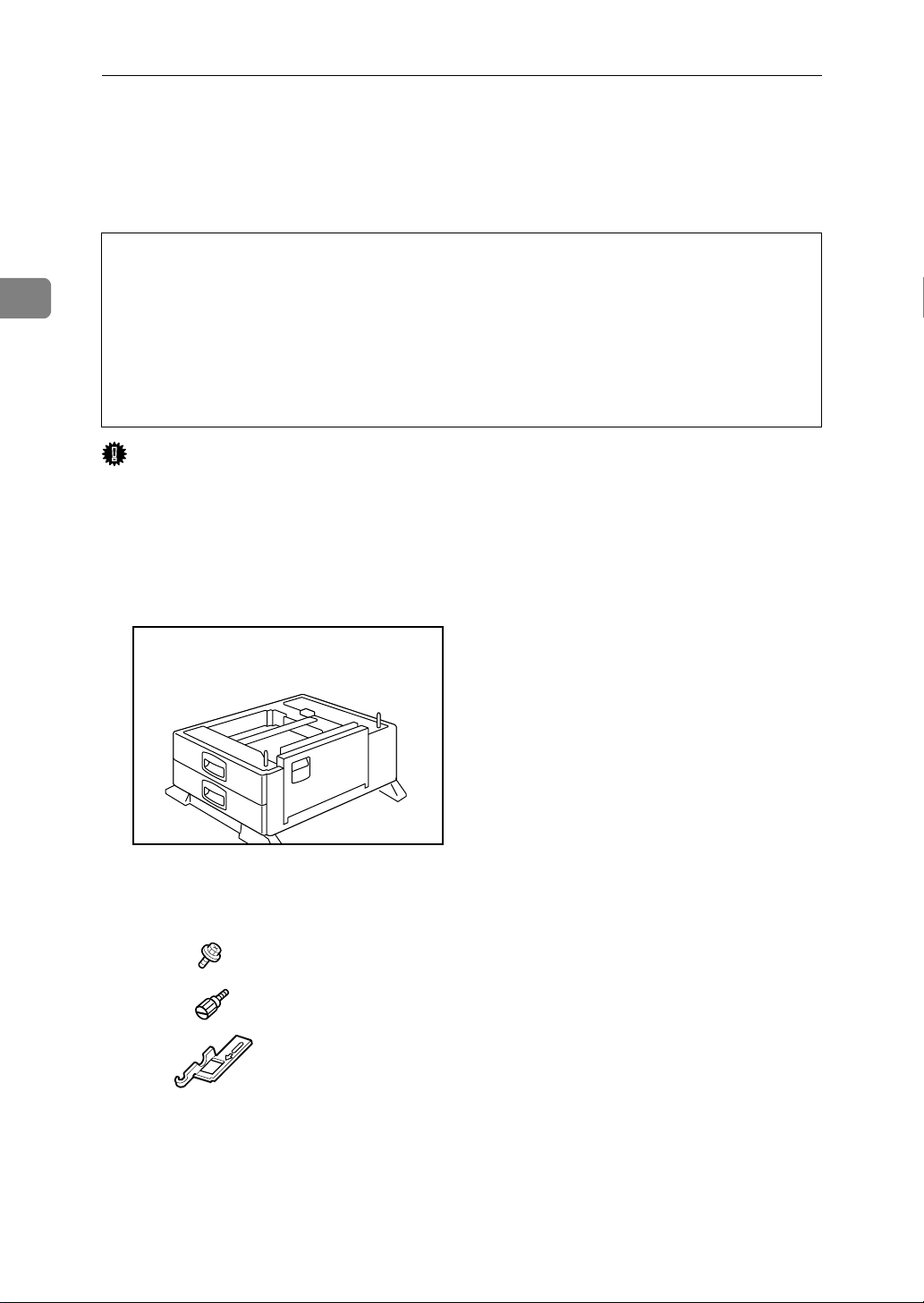
A Check the package contains the following:
❖ Paper Feed Unit PB 3020
1
2
3
AQV039S
AQV720S
1. Screw
2. Knob Screw (Finger type)
3. Lock Plate
10
Page 22
Attaching Paper Feed Unit PB 3020
B Confirm that the printer is turned off, and the power cord is unplugged
from the wall outlet.
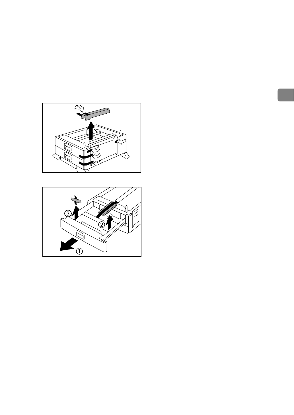
C Remove the tape that holds the paper feed unit, and then remove the pack-
ing material.
Do not remove the tape that holds the connector cable inside the connector
cover on the back of the paper feed unit in this step. It is removed in the further step.
AQV041S
2
AQV040S
11
Page 23
2
Installing Options
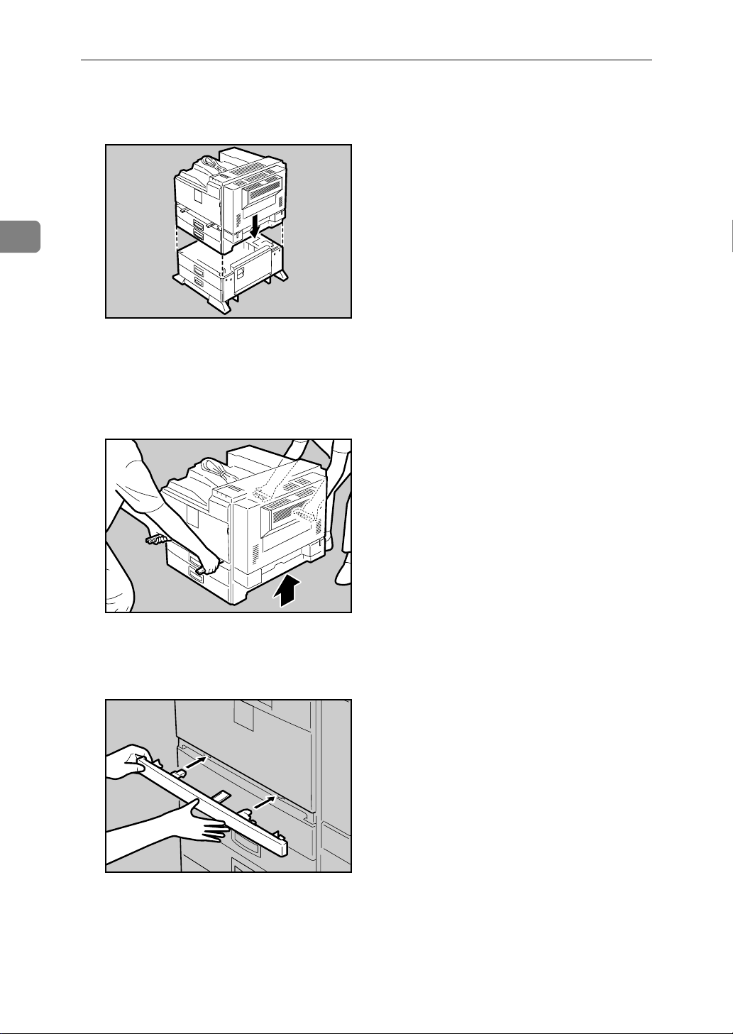
D Align the printer with the two upright pins on the paper feed unit and then
lower the printer slowly.
AQV007S
• The printer should be held by least two people.
• When lifting the printer, pull out the grips from the front of the printer.
One person should hold the grips on the front and another person should
hold the grips on the rear.
AQV003S
E Push the grips into the printer. Take out the cover inside Tray 2 and attach
it between the paper tray and the front cover.
AQV001S
12
Page 24
Attaching Paper Feed Unit PB 3020
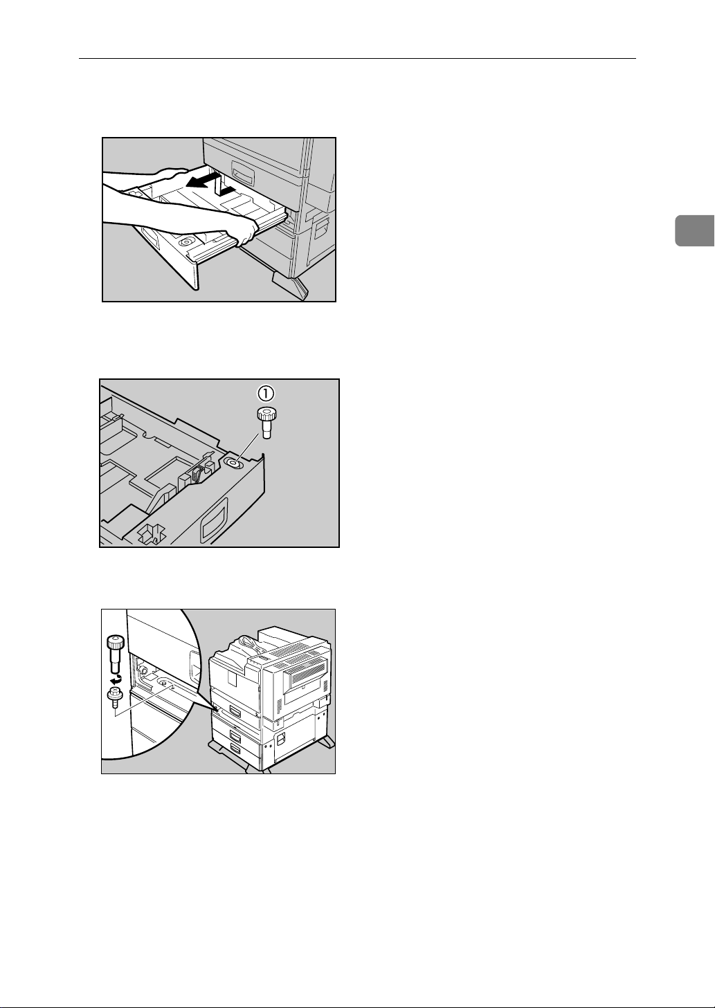
F Pull the second paper tray (Tray 2) until it stops. After that, lift it slightly,
and then pull it out.
AQV732S
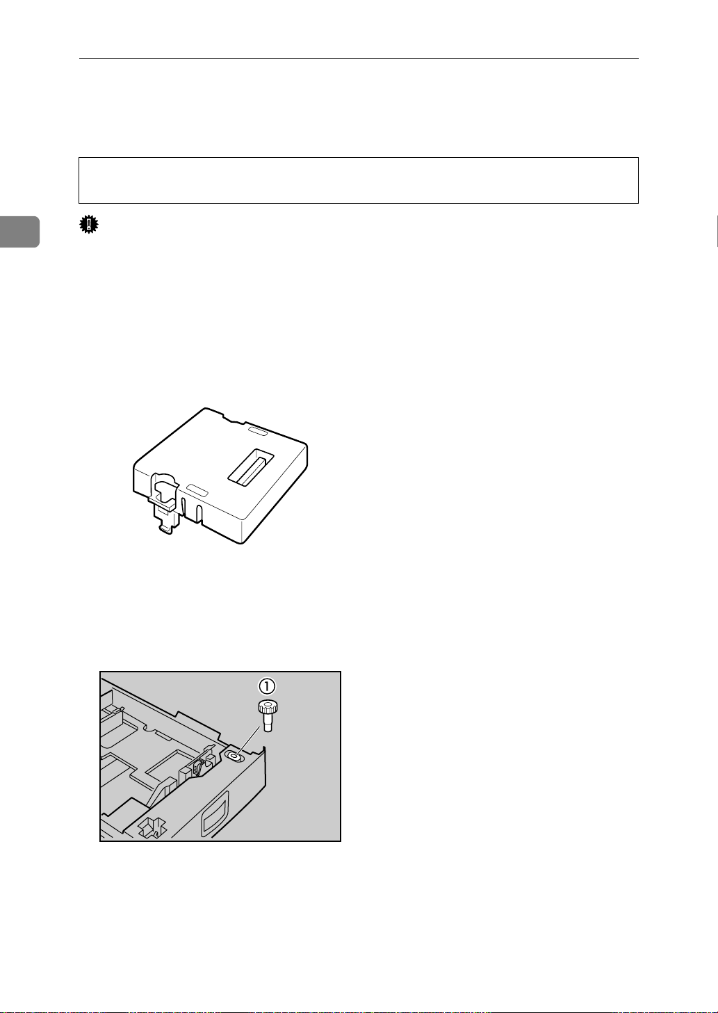
G Pull out the first paper tray (Tray 1) , and take the screwdriver (1) from the
tray.
2
AQV222S
H Lock the Paper Bank and the printer with the screw.
AQV731S
Be sure to return the screwdriver to the paper tray after using it.
13
Page 25
2
Installing Options
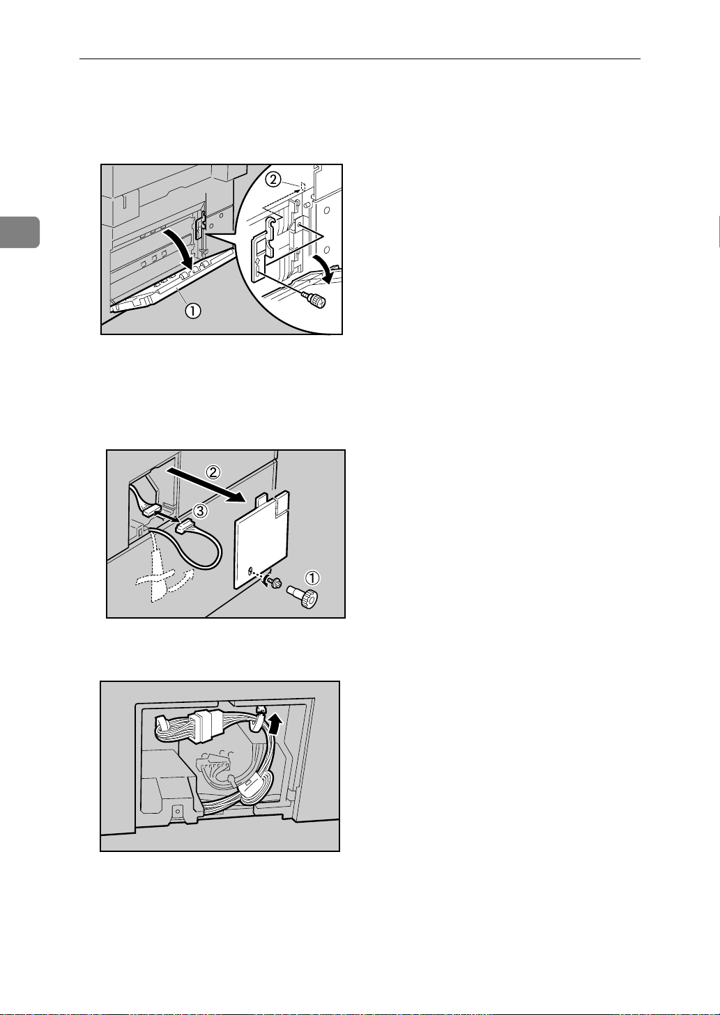
I Open the lower vertical paper feed cover on the right side of the paper feed
unit (1). Hang the lock plate hook in the hole inside (2), and then fasten the
plate with the knob screw using your fingers.
AQV042S
J Close the lower vertical paper feed cover.
K Open the connector cover (2), remove the tape that holds the connector ca-
ble and attach the connector cables (3) as shown in the illustration.
AQV009S
L Fasten the band as shown until it clicks to secure the cable.
AQV522S
14
Page 26
Attaching Paper Feed Unit PB 3020
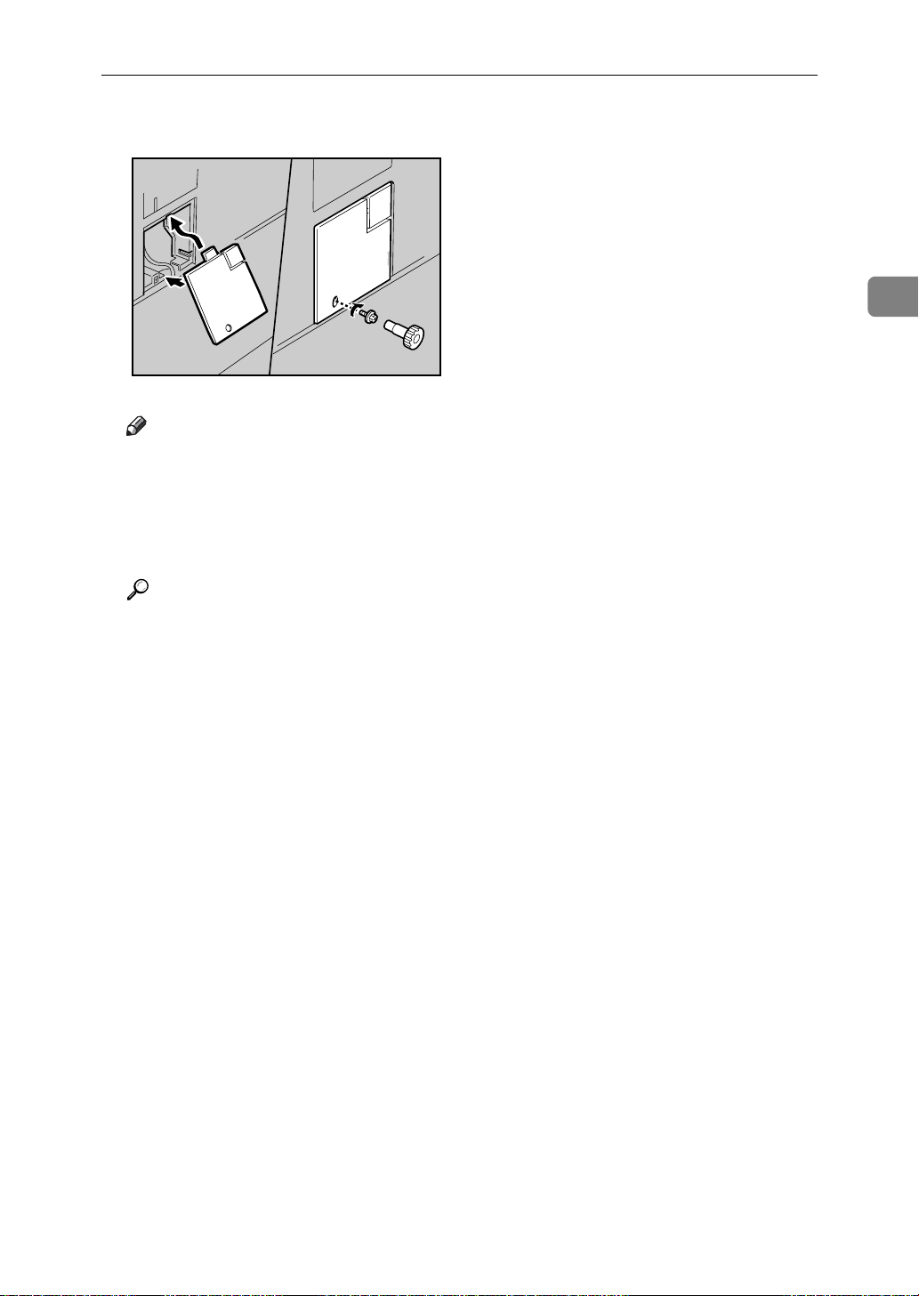
M Close the connector cover.
AQV010S
Note
❒ Print a configuration page to confirm that the paper feed unit is properly
installed.
❒ If the paper feed unit is not installed properly, reinstall it following this
procedure. If you cannot install it properly even after attempting reinstallation, contact your sales or service representative.
2
Reference
For printing the configuration page, see “Printing the Test Page”, Quick Installation Guide.
For loading paper onto the paper tray, see p.71 “Loading Paper”.
When adjusting the printing position, see p.96 “Adjusting Tray Registration”.
15
Page 27
Installing Options
R
Attaching User Account Enhance Unit Type E
CAUTION:
• Do not touch the inside of the controller board compartment. Doing so may
cause a malfunction or a burn.
2
Important
❒ Before touching the User Account Enhance Unit, ground yourself by touch-
ing something metal to discharge any static electricity. Static electricity can
damage User Account Enhance Unit.
❒ Do not subject User Account Enhance Unit to physical shocks.
A Check the package contains the following:
❖ User Account Enhance Unit Type E
AET080S
B Turn off the printer.
C Pull out the first paper tray (Tray 1) and take the screwdriver (1) from the
tray. Each screw to be removed requires this screwdriver.
AQV222S
16
Page 28
Attaching User Account Enhance Unit Type E
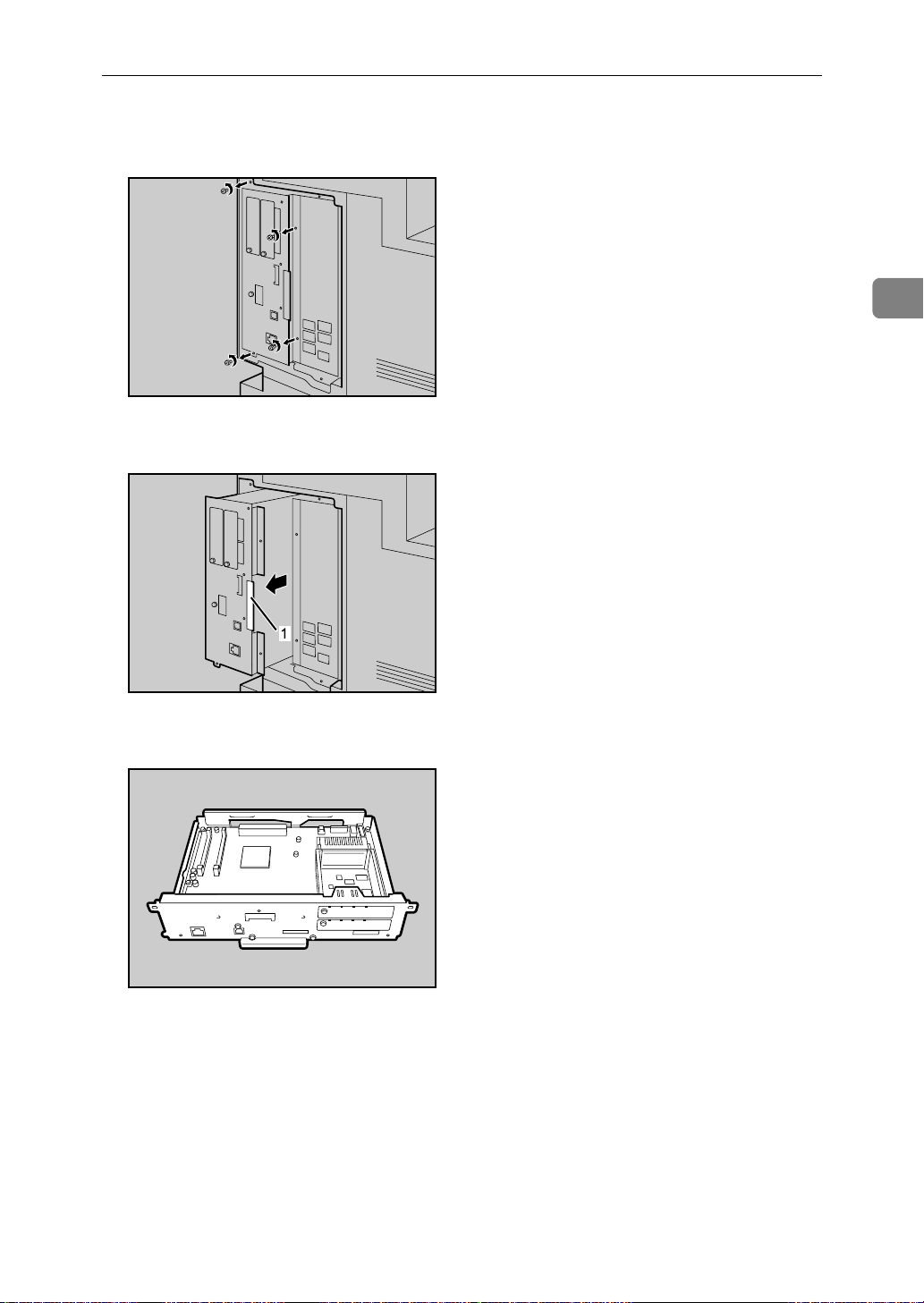
D Remove the screws as shown by turning them counterclockwise using the
provided screwdriver.
AQV500S
E Hold the part (1) of the controller board, and then slide it out completely.
2
AQV501S
F Place the controller board on a flat surface.
AQV516S
17
Page 29
2
Installing Options
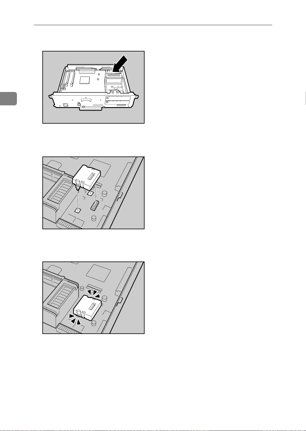
G Be sure to install the User Account Enhance Unit as shown.
AQU012S
H Align the notch of User Account Enhance Unit, and then insert it into the
controller board, pressing it down until it clicks into place.
AQU013S
I Make sure that User Account Enhance Unit is firmly connected to the con-
troller board.
AQU014S
18
Page 30
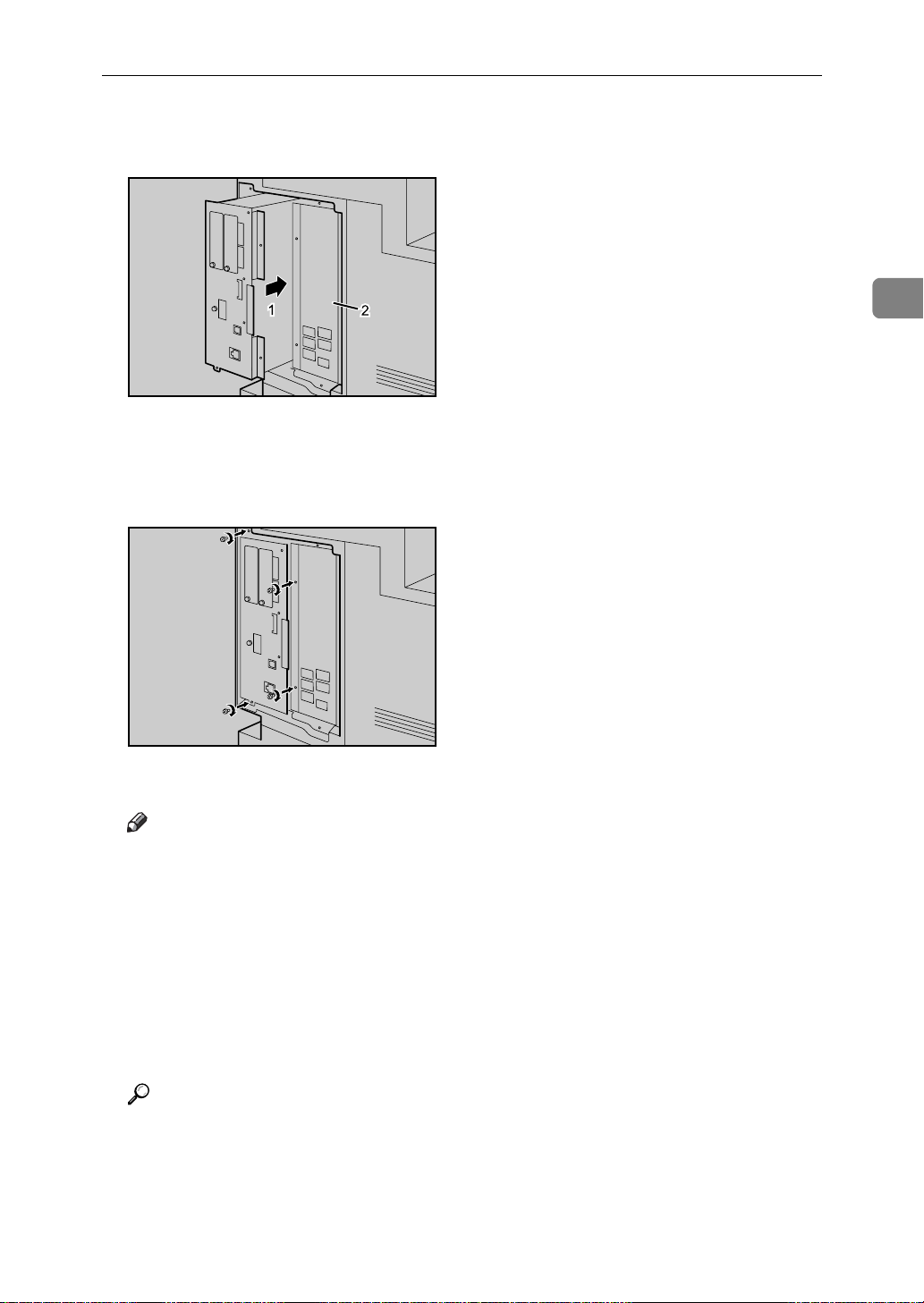
Attaching User Account Enhance Unit Type E
J Store the controller board (1) into the printer while gently pressing the
cover (2).
AQV502S
Push in the controller board firmly to align the rails in the printer's compartment.
2
K Fasten all the screws which you removed in step
AQV503S
The printer may malfunction if the controller board is not properly installed.
Note
❒ Be sure to return the screwdriver to the paper tray after using it.
❒ After finishing installation, you can check whether the User Account En-
hance Unit is properly installed: Print the configuration page from the
[List/Test Print] menu. If it is installed properly, “Accounting Module” will
appear for “Device Connection” on the configuration page.
❒ If the User Account Enhance unit is not installed properly, reinstall it fol-
lowing this procedure. If you cannot install it properly even after attempting reinstallation, contact your sales or service representative.
.
D
❒ Install the controller board carefully to prevent any malfunction.
Reference
For printing the configuration page, see “Printing the Test Page”, Quick Installation Guide.
19
Page 31

Installing Options
R
Attaching Printer Hard Disk Drive Type 8100
CAUTION:
• Do not touch the inside of the controller board compartment. Doing so may
cause a machine malfunction or a burn.
2
Important
❒ Before installation, be sure to remove all SDRAM modules from the controller
board to prevent from damaging them.
❒ Before touching the hard disk drive, touch something metal to discharge any
static electricity. Static electricity can damage the hard disk drive.
❒ Do not subject the hard disk drive to physical shocks.
❒ Before using the new hard disk drive, be sure to make the settings in the print-
er driver.
A Check the package contains the following:
❖ Hard Disk Drive
AQV518S
❖ Flat Cable
AQC500S
20
Page 32

❖ Power Cable
❖ Supplied Screws
❖ Protective Sheet
Attaching Printer Hard Disk Drive Type 8100
2
AQV760S
AQV739S
AQV740S
B Turn off the printer.
C Pull out the first paper tray (Tray 1) and take the screwdriver (1) from the
tray. Each screw to be removed requires this screwdriver.
AQV222S
21
Page 33

2
Installing Options
D Remove the screws as shown by turning them counterclockwise using the
provided screwdriver.
AQV500S
E Hold the part (1) of the controller board, and then slide it out completely.
AQV501S
F Place the controller board on a flat surface.
AQV516S
22
Page 34

Attaching Printer Hard Disk Drive Type 8100
G Remove the default or optional SDRAM module before installing the hard
disk drive. Press down the levers on both sides (1) to remove the SDRAM
module (2).
AQV763S
Be sure not to leave any SDRAM module in the slots. Doing so may damage
SDRAM modules when installing the hard disk drive.
H Place the protective sheet on the controller board as shown, to protect the
controller board.
2
AQV736S
I Connect the flat cable (1) and power cable (2) to the hard disk drive.
1
2
AQV519S
23
Page 35

2
Installing Options
J Carefully insert the hard disk drive into the controller board as shown.
There is a lip cut into the center of the front end of the hard disk drive's casing.
Hook this part over the flange (curled part) in the slot (1) on the controller
board, and then align (2) and (3) with the screw holes in the rear edge of the
controller board.
AQV517S
K Fasten the screws clockwise as shown by using the provided screwdriver,
to secure the hard disk drive.
AQV730S
L Connect the power cable to the socket on the controller board.
AQV520S
24
Page 36

Attaching Printer Hard Disk Drive Type 8100
M Connect the blue end of the flat cable to the socket on the controller board.
AQV521S
When installing an SDRAM module on the controller board, do not store the
controller board to the printer, and attach an SDRAM module.
N Remove the protective sheet when installing the hard disk drive is com-
pleted.
2
AQV737S
Be sure to check whether the hard disk drive is completely secured before removing the sheet.
O Install the default or optional SDRAM modules into the slot.
For details about installing the SDRAM modules, see p.27 “Attaching Memory Unit Type D 128MB, Memory Unit Type E 256MB (SDRAM Module)”.
25
Page 37

2
Installing Options
P Store the controller board (1) into the printer while gently pressing the
cover (2).
AQV502S
Push in the controller board firmly to align the rails in the printer's compartment.
Q Fasten all the screws which you removed in step
AQV503S
The printer may malfunction if the controller board is not properly installed.
.
D
R When the power is turned on, the hard disk drive will be formatted auto-
matically.
Note
❒ Be sure to return the screwdriver to the paper tray after using it.
❒ After finishing installation, you can check whether the hard disk drive is
properly installed: Print the configuration page from the [List/Test Print]
menu. If it is installed properly, “Printer Hard Disk Drive” will appear for
“Device Connection” on the configuration page.
❒ If the hard disk drive is not installed properly, reinstall it following this
procedure. If you cannot install it properly even after attempting reinstallation, contact your sales or service representative.
26
❒ Install the controller board carefully to prevent any malfunction.
Reference
For printing the configuration page, see “Printing the Test Page”, Quick Installation Guide.
Page 38

Attaching Memory Unit Type D 128MB, Memory Unit Type E 256MB (SDRAM Module)
R
Attaching Memory Unit Type D 128MB,
Memory Unit Type E 256MB (SDRAM
Module)
CAUTION:
• Do not touch the inside of the controller board compartment. Doing so may
cause a malfunction or a burn.
Important
❒ Be sure to install SDRAM modules after installing the hard disk drive.
❒ Before touching the memory unit, ground yourself by touching something
metal to discharge any static electricity. Static electricity can damage the
memory unit.
❒ Do not subject the memory unit to physical shocks.
❒ Available memory varies depending on a model type.
❒ Before using the new memory unit, Be sure to make settings in the printer
driver.
2
A Turn off the printer.
B Pull out the first paper tray (Tray 1) and take the screwdriver (1) from the
tray. Each screw to be removed requires this screwdriver.
AQV222S
27
Page 39

2
Installing Options
C Remove the screws as shown by turning them counterclockwise using the
provided screwdriver.
AQV500S
D Hold the part (1) of the controller board, and then slide it out completely.
AQV501S
E Place the controller board on a flat surface.
AQV516S
28
Page 40

Attaching Memory Unit Type D 128MB, Memory Unit Type E 256MB (SDRAM Module)
F Be sure to install the SDRAM module into the slot as shown.
AQV560S
Two slots are provided for the SDRAM modules.
The default SDRAM module is installed in the inner slot.
To install an additional memory, attach an additional SDRAM module to the
outer slot, or replace the default SDRAM module.
G When installing an SDRAM module in a vacant slot, align the notch of the
SDRAM module with the slot, and then insert the module vertically.
2
AQV761S
H Press down the SDRAM module, until it clicks into place.
AQV762S
29
Page 41

2
Installing Options
I When replacing the default SDRAM module, press down the levers on
both sides ( ) to remove the default module ( ).
AQV763S
Install a new SDRAM module.
To increase memory capacity to the maximum of 512 MB, remove the default
SDRAM module, and then install two 256 MB SDRAM modules.
J Store the controller board (1) into the printer while gently pressing the
cover (2).
AQV502S
Push in the controller board firmly to align the rails in the printer's compartment.
K Fasten all the screws which you removed in step
AQV503S
The printer may malfunction if the controller board is not properly installed.
30
.
C
Page 42

Attaching Memory Unit Type D 128MB, Memory Unit Type E 256MB (SDRAM Module)
Note
❒ Be sure to return the provided screwdriver to its original position on the
inside of the front cover.
❒ After finishing the installation, you can check the memory unit is properly
installed: Print the configuration page from the [List/Test Print] menu. If it is
installed properly, the memory capacity will appear under “Total Memory” on the configuration page.
❒ The table below shows the total SDRAM module capacities.
Standard Extended Total
128 MB 128 MB 256 MB
128 MB 256 MB 384 MB
256 MB 128 MB 384 MB
256 MB 256 MB 512 MB
❒ If the memory unit is not properly installed, repeat this procedure. If you
cannot install it properly even after reinstallation, contact your sales or
service representative.
❒ Install the controller board carefully to prevent any malfunction.
2
Reference
For printing the configuration page, see “Printing the Test Page”, Quick Installation Guide.
31
Page 43

Installing Options
R
Attaching IEEE 802.11b Interface Unit
CAUTION:
• Do not touch the inside of the controller board compartment. Doing so may
cause a machine malfunction or a burn.
2
Important
❒ For using the IEEE 802.11b interface unit, installing the optional SDRAM
module is required. If the optional SDRAM module is not installed, the printer does not detect the unit, and also it does not function because of memory
shortage.
❒ Before touching the 802.11b interface unit, touch something metal to dis-
charge any static electricity. Static electricity can damage the 802.11b interface
unit.
❒ Do not subject the 802.11b interface unit to physical shocks.
A Check the contents of the package for the following:
❖ IEEE 802.11b Interface Unit
• Interface Unit
AAL151S
•Card
ZHBP420E
32
Page 44

• Antenna
Attaching IEEE 802.11b Interface Unit
ZHBP430E
• Antenna Cap
AAL888S
B Turn off the power, and then unplug the power cable.
C Remove the screw by turning it counterclockwise using the provided
screwdriver, and then remove the cover of the 802.11b interface board slot.
AQV509S
2
The removed cover is not used when installing the interface unit.
D Fully insert the 802.11b interface board into the slot.
AQV510S
33
Page 45

2
Installing Options
E Tighten the two screws to secure the interface board.
AQV523S
F Attach the antenna to the card with the label facing down and the uneven
side of the antenna facing up.
AET096S
G With the antenna and the indented end toward you, slowly insert the inter-
face card until it stops.
AQV511S
34
Page 46

Attaching IEEE 802.11b Interface Unit
H Hold the antenna cap with the cut off corners towards you and fit it over the
card.
AQV512S
Note
❒ After finishing installation, you can check the 802.11b interface unit is
properly installed: Print the configuration page from the [List/Test Print]
menu. If it is installed properly, “IEEE 802.11b” will appear for “Device
Connection” on the configuration page.
❒ If the 802.11b interface unit is not installed properly, reinstall it following
this procedure. If you cannot install it properly even after attempting reinstallation, contact your sales or service representative.
2
Reference
For printing the configuration page, see “Printing the Test Page”, Quick Installation Guide.
35
Page 47

Installing Options
R
Attaching IEEE 1284 Interface Board Type A
CAUTION:
• Do not touch inside the controller board compartment. Doing so may cause
a machine malfunction or a burn.
2
Important
❒ Before handling the 1284 interface board, touch something metal to discharge
static electricity. Static electricity thing damage the 1284 interface board.
❒ Do not subject the 1284 interface board to physical shocks.
A Check the package contains the following:
❖ IEEE 1284 Interface Board Type A
ABT041S1
B Turn off the power, and then unplug the power cable.
C Remove the screw by turning it counterclockwise using the provided
screwdriver, and then remove the cover of the IEEE 1284 interface board
slot.
AQV509S
The removed cover is not used when installing the 1284 interface board.
36
Page 48

Attaching IEEE 1284 Interface Board Type A
D Fully insert the 1284 interface board into the slot.
AQV513S
Confirm that the 1284 interface board is firmly connected to the controller
board.
E Tighten the two screws to secure the 1284 interface board.
2
AQV524S
Note
❒ Use the supplied adaptor to make the connection with the computer.
❒ After finishing installation, you can check the 1284 interface board is prop-
erly installed: Print the configuration page from the [List/Test Print] menu.
If it is installed properly, “Parallel Interface” will appear for “Device Connection” on the configuration page.
❒ If the 1284 interface board is not installed properly, reinstall it following
this procedure. If you cannot install it properly even after attempting reinstallation, contact your sales or service representative.
Reference
For printing the configuration page, see “Printing the Test Page”, Quick Installation Guide.
37
Page 49

2
Installing Options
Attaching Gigabit Ethernet Board
Important
❒ The printer's ethernet and USB ports are not available when the gigabit eth-
ernet board is attached to the printer. Instead, you can use the ethernet port
and USB port mounted on the board.
❒ Before handling the gigabit ethernet board, ground yourself by touching
something metal to discharge any static electricity. Static electricity can damage the gigabit ethernet board.
❒ Do not subject the gigabit ethernet board to physical shocks.
A Check the contents of the box.
❖ Gigabit Ethernet Board Type A
AGY096S
❖ Protective caps (one each for the ethernet port and the USB port)
AGY097S
B Turn off the power, and then unplug the power cable.
38
Page 50

Attaching Gigabit Ethernet Board
C Disconnect the cables from the ethernet port and the USB port of the print-
er, and cover each port with its protective cap.
AQV562S
D Remove the screw by turning it counterclockwise using the provided
screwdriver, and then remove the cover of the Gigabit ethernet board slot.
2
AQV509S
The removed cover is not used when installing the interface unit.
E Fully insert the Gigabit ethernet board into the slot.
AQV514S
39
Page 51

2
Installing Options
F Tighten the two screws to secure the Gigabit ethernet board.
AQV525S
Check the Gigabit ethernet board is connected firmly to the controller board.
Note
❒ After finishing installation, check the Gigabit ethernet board is installed
properly: print the configuration page from the [List/Test Print] menu. If it
is installed properly, you will see “Gigabit Ethernet Board” for “Device
Connection” on the configuration page.
❒ If the Gigabit ethernet board is not installed properly, reinstall it following
this procedure. If you cannot install it properly even after attempting reinstallation, contact your sales or service representative.
❒ You need to make settings with the control panel before using the gigabit
ethernet board. For details, see p.51 “Ethernet Configuration”.
Reference
For details about printing the configuration page, see “Printing the Test
Page”, Quick Installation Guide.
40
Page 52

Attaching VM Card Type D
Attaching VM Card Type D
Important
❒ For using the VM card, installing the optional SDRAM module is required. If
the optional SDRAM module is not installed, the printer does not detect the
unit, and also it does not function because of memory shortage.
❒ Protect VM Card Type D from physical shocks.
❒ Using the upper slot is recommended for inserting the unit.
A Check the package contains the following:
❖ VM Card Type D
2
AET104S
B Turn off the power, and then unplug the power cable.
C Remove the cover of the expansion card slot.
AQV504S
D Carefully insert the VM card into the slot, until the card clicks into place.
AQV553S
41
Page 53

2
Installing Options
Note
❒ Do not touch the VM card while the printer is in use. It may come loose,
even if pushed only slightly.
42
Page 54

Attaching Data Storage Card Type A
Attaching Data Storage Card Type A
Important
❒ Protect the data storage card from physical shocks.
❒ Using the upper slot is recommended for inserting the unit.
A Check the package contains the following:
❖ Data Storage Card Type A
AET104S
2
B Turn off the power, and then unplug the power cable.
C Remove the cover of the expansion card slot.
AQV504S
D
Carefully insert the data storage card into the slot, until the card clicks into place.
AQV553S
Note
❒ Do not touch the data storage card while the printer is in use. It may come
loose, even if pushed only slightly.
43
Page 55

2
Installing Options
44
Page 56

3. Connecting the Printer
Network Connection
Follow the procedure below to connect the printer to the computer through the
network. Prepare the hub and other network devices before connecting the
10BASE-T or 100BASE-TX cable to the printer's Ethernet port.
Alternatively, the optional gigabit ethernet board, which supports 1000BASE-T,
is available.
Important
❒ Use shielded Ethernet cable. Unshielded cables create electromagnetic inter-
ference that could cause malfunctions.
❒ The Ethernet cable is not supplied with this printer. Select your cable accord-
ing to the network environment.
A Attach the supplied ferrite core at the printer end of the Ethernet cable.
AQV744S
B Connect the Ethernet cable to the Ethernet port.
AQV507S
C Connect the other end of the cable to the printer's network, such as a hub.
45
Page 57

3
Connecting the Printer
Using the Gigabit Ethernet cable
A For using the gigabit ethernet cable, attach one ferrite core at the printer
end of the Ethernet cable, and attach the other ferrite core about 10 cm (4
inches) ( ) from this core making a loop as shown.
AQV564S
B Connect the ethernet cable to the gigabit ethernet board.
AQV551S
C Connect the other end of the cable to the printer's network, such as a hub.
Note
❒ The printer's ethernet and USB ports are not available when the gigabit
ethernet board is attached to the printer.
Reference
For details about network environment settings, see Software Guide.
For details about attaching the gigabit ethernet board, see p.38 “Attaching
Gigabit Ethernet Board”.
46
Page 58

Reading the LED Lamps
❖ For standard ethernet port
Network Connection
3
AQV563S
1. Green: comes on when the printer
is properly connected to the network.
❖ For gigabit ethernet board
AQV563S
1. Yellow: comes on 100BASE-TX is
being used.
Green and yellow lamps are lit when
1000BASE-T is being used.
2. Yellow: comes on when 100BASE-
TX is being used. It comes off when
10BASE-T is being used.
2. Green: comes on when 10BASE-T
is being used.
47
Page 59

3
Connecting the Printer
USB Connection
Important
❒ The USB2.0 cable is not supplied. Obtain a cable that is suitable for the com-
puter you are using.
❒ USB connection is possible under Windows Me/2000/XP, Windows Server
2003, Mac OS 9.x, and Mac OS X.
❒ Windows Me supports USB1.1 speeds.
❒ USB connection with Macintosh is only possible via the printer's USB port.
A Connect the square-shaped connector of the USB2.0 cable to the USB port.
AQV506S
B If the gigabit ethernet board is attached, connect the square-shaped connec-
tor of the USB2.0 cable to the USB port of the board.
AQV550S
The printer's ethernet and USB ports are not available when the gigabit ethernet board is attached to the printer.
C Connect the opposite end's flat connector to devices such as your compu-
ter's USB interface, or a USB hub.
Reference
For details about attaching the gigabit ethernet board, see p.38 “Attaching
Gigabit Ethernet Board”.
For details about settings for USB connection printing, see Software Guide.
48
Page 60

Parallel Connection
Parallel Connection
Important
❒ The parallel interface cable is not supplied with the printer.
❒ The printer's parallel connection is a standard bidirectional interface that re-
quires an IEEE 1284-compliant 36-pin parallel cable and host computer parallel port.
❒ Use shielded interface cable. Unshielded cables create electromagnetic inter-
ference that could cause malfunctions.
❒ Voltage rating of the computer's parallel port: DC 5 V (max.)
A Turn off the printer and computer.
B Connect the cable to the interface socket of the IEEE 1284 interface board.
3
AQV561S
C Securely attach the other end of the parallel cable to your computer's paral-
lel port. Secure the cable.
Reference
For details about settings for parallel connection printing, see Software
Guide.
49
Page 61

3
Connecting the Printer
50
Page 62

4. Configuration
Ethernet Configuration
Make the following network settings according to the network interface you are
using.
You can use SmartDeviceMonitor for Admin or a Web browser to make IP address-related settings in a TCP/IP-capable environment.
Important
❒ Configure the printer for the network using the control panel.
❒ The following table shows the control panel settings and their default values.
These items appear in the “Host Interface” menu.
Setting Name Value
DHCP On
IPv4 Address 011.022.033.044
Subnet Mask 000.000.000.000
Gateway Address 000.000.000.000
Frame Type (NW) Auto
Active Protocol • IPv4:
Active
•IPv6:
Active
• NetWare:
Active
•SMB:
Active
• AppleTalk:
Active
Ethernet Speed Auto
LAN Type Auto
Note
❒ If DHCP is in use, the IP address, subnet mask, and gateway address are all
set automatically.
❒ Make this setting only when it is necessary. See Software Guide.
51
Page 63

4
Configuration
A Press the {Menu} key.
AQV251S
B Select [Host Interface] using {T} or {U}, and then press the {q Enter} key.
C Select [Network Setup] using {T} or {U}, and then press the {q Enter} key.
D Select [Active Protocol] using {T} or {U}, and then press the {q Enter} key.
E Select the network protocol using {T} or {U}, and then press the {q Enter} key.
F Select [Active] or [Not Active] using {T} or {U}, and then press the {q Enter} key.
Set other protocols you need to set in the same way.
•Select [Not Active] for unused protocols.
52
• Enable IPv4 to use the Pure IPv4 environment of NetWare 5/5.1, NetWare 6/6.5.
Page 64

Ethernet Configuration
G Press the {Escape} key until the screen returns to the [Network Setup] menu.
H If you use IPv4, assign the IPv4 address to the printer. Select [IPv4 Settings]
using {T} or {U}, and then press the {q Enter} key.
To get the IP address for the printer, contact your network administrator.
I To specify the IP Address, Select [IPv4 Address] using {T} or {U}, and then
press the {q Enter} key.
If you use IPv4, assign also Subnet Mask and Gateway Address.
J Enter the address using {T} or {U}, and then press the {q Enter} key.
Press the {T} or {U} key to enter the left most entry field of the address. After
entering the left field, press the {V} key, and then you can enter the next field.
After completing to enter in the all fields, press the {q Enter} key. Use this
method to assign Subnet Mask and Gateway Address.
4
• Do not set “011.022.033.044” as the IP address.
K Press the {Menu} key to return to the initial screen.
L Print a configuration page to confirm the settings made.
Reference
For details about printing the configuration page, see “Printing the Test
Page”, Quick Installation Guide.
53
Page 65

Configuration
Using DHCP - Detecting the Network Address Automatically
Important
❒ When you use this printer in DHCP environment, select [DHCP] following this
procedure.
❒ When [DHCP] is selected, you cannot make settings for the following items:
• IP Address
•Subnet Mask
• Gateway Address
❒ Consult your network administrator for information about making network
settings.
4
A Press the {Menu} key.
AQV251S
B Select [Host Interface] using {T} or {U}, and then press the {q Enter} key.
C Select [Network Setup] using {T} or {U}, and then press the {q Enter} key.
D Select [IPv4 Settings] using {T} or {U}, and then press the {q Enter} key.
54
Page 66

Ethernet Configuration
E Select [DHCP] using {T} or {U}, and then press the {q Enter} key.
F Select [On] or [Off]using {T} or {U}, and then press the {q Enter} key.
The address will be detected by the printer.
The default setting is [Off].
G Press the {Menu} key to return to the initial screen.
H Print a configuration page to confirm the settings made.
Reference
For details about printing the configuration page, see “Printing the Test
Page”, Quick Installation Guide.
Making Network Settings for Using Netware
If you use NetWare, select the frame type for NetWare.
Select one of the items below if necessary.
•Auto (Default)
•Ethernet II
• Ethernet 802.2
• Ethernet 802.3
• Ethernet SNAP
4
Important
❒ Usually, use the default setting (“Auto”). When you first select “Auto”, the
frame type detected by the printer is adopted. If your network can use more
than two frame types, the printer may fail to select the correct frame type if
“Auto” is selected. In this case, select the appropriate frame type.
55
Page 67

4
Configuration
A Press the {Menu} key.
AQV251S
B Select [Host Interface] using {T} or {U}, and then press the {q Enter} key.
C Select [Network Setup] using {T} or {U}, and then press the {q Enter} key.
D Select [Frame Type (NW)] using {T} or {U}, and then press the {q Enter} key.
E Select the frame type using {T} or {U}, and then press the {q Enter} key.
F Press the {Menu} key to return to the initial screen.
G Print a configuration page to confirm the settings made.
Reference
For details about printing the configuration page, see “Printing the Test
Page”, Quick Installation Guide.
56
Page 68

IEEE 802.11b (Wireless LAN) Configuration
IEEE 802.11b (Wireless LAN) Configuration
Configure the printer to use IEEE 802.11b (Wireless LAN). The following table
shows the control panel settings and their default values. These items appear in
the [Host Interface] menu.
Setting Name Default Value
Communication Mode 802.11 Ad hoc
Channel
Communication Speed Auto
SSID blank
WEP Not Active
Important
•
(1-11) 11
•
(1-13) 13
❒ For using the IEEE 802.11b interface unit, installing the optional SDRAM
module is required. If the optional SDRAM module is not installed, the printer does not detect the unit, and also it does not function because of memory
shortage.
❒ To use IEEE 802.11b (Wireless LAN), set as the followings using the control
panel: press the {Menu} key, and then select [Host Interface], [Network Setup],
[LAN Type], and then [IEEE 802.11b]. Also, set the IP Address, Subnet Mask,
Gateway Address, DHCP, Frame Type (NW), and Active Protocol under the
[Network Setup] menu. For details about setting items, see “Configuring the
Printer for the Network”, Software Guide.
❒ The 802.11b interface unit cannot be used simultaneously with a standard
ethernet interface.
4
A Press the {Menu} key.
AQV251S
57
Page 69

Configuration
B Select [Host Interface] using {T} or {U}, and then press the {q Enter} key.
C Select [IEEE 802.11b] using {T} or {U}, and then press the {q Enter} key.
4
D Select [Comm. Mode] using {T} or {U}, and then press the {q Enter} key.
E Select the transmission mode of IEEE 802.11b using {T} or {U}, and then
press the {q Enter} key.
•The factory default is [802.11 Ad hoc].
• To use an IEEE 802.11b card for which the SSID (Network Name) setting is
not necessary, select [Ad hoc].
• The transmission mode of IEEE 802.11b can also be set using a Web browser. For details, see Web browser, and “Configuring the Network Interface
Board Using Web Browser”, Software Guide.
F If [802.11 Ad hoc] or [Ad hoc] is selected for [Comm. Mode], set the channel to
use for transmission.
Confirm the network administrator for the channel to use.
G In the [IEEE 802.11b] menu, select [Channel] using {T} or {U}, and then press
the {q Enter} key.
58
Page 70

IEEE 802.11b (Wireless LAN) Configuration
H Enter the channel using {T} or {U}, and then press the {q Enter} key.
I Set [Trans. Speed] in the same way.
The factory default is [Auto]. If you need to change the transmitting speed depending on environment you are using, select the appropriate transmitting
speed.
J Print a configuration page to confirm the settings made.
Reference
For details about printing the configuration page, see “Printing the Test
Page”, Quick Installation Guide.
Setting SSID
If [Infrastructure] or [802.11 Ad hoc] is selected for [Comm. Mode], set SSID to use for
transmission.
Confirm the network administrator for SSID to use.
A In the [IEEE 802.11b] menu, select [SSID] using {T} or {U}, and then press the
{q Enter} key.
If an SSID has been set, you can check the SSID setting.
B select [Enter ID] using {T} or {U}, and then press the {q Enter} key.
4
C Enter characters using {T} or {U}, and then press the {q Enter} key.
The number of character you have entered is displayed on the top right of the screen.
The characters that can be used are ASCII 0x20-0x7e (32 bytes), 16 digits.
59
Page 71

Configuration
D Print a configuration page to confirm the settings made.
Reference
SSID can also be set using a Web browser. For details, see the Web Image
Monitor Help, and “Configuring the Network Interface Board Using Web
Browser”, Software Guide.
WEP key can also be set using a Web browser. For details, see Web Image
Monitor Help.
For details about printing the configuration page, see “Printing the Test
Page”, Quick Installation Guide.
Setting a WEP key
4
In the case of using a WEP key on a network, activate the WEP setting to be used
for communication along with WEP.
Confirm the network administrator for the WEP Key to use.
A In the [IEEE 802.11b] menu, select [Security Method] using {T} or {U}, and then
press the {q Enter} key.
B Select [WEP] using {T} or {U}, and then press the {q Enter} key.
When activating the WEP Setting, you will need to enter the WEP key. If you
have not entered the key, be sure to enter it.
C Select [Change (HEX)] or [Change (ASCII)] using {T} or {U}, and then press the
{q Enter} key.
60
Page 72

IEEE 802.11b (Wireless LAN) Configuration
D Enter the characters using {T} or {U}, and then press the {q Enter} key.
When entering the character, pressing {q Enter} will mask it with an asterisk
for security reasons.
When using 64 bit WEP, up to 10 characters can be used for hexadecimal and
up to five characters for ASCII. When using 128 bit WEP, up to 26 characters
can be used for hexadecimal and up to 13 characters for ASCII.
The number of characters that can be entered is limited to 10 or 26 for hexadecimal and 5 or 13 for ASCII.
For ASCII character strings, each capital letter and lowercase letter is recognized respectively.
E Press the {Menu} key to return to the initial screen.
F Print a configuration page to confirm the settings made.
4
Reference
WEP key can also be set using a Web browser. For details, see Web Image
Monitor Help.
For details about printing the configuration page, see “Printing the Test
Page”, Quick Installation Guide.
61
Page 73

4
Configuration
62
Page 74

5. Paper and Other Media
Paper and Other Media Supported by This Printer
This section describes the paper size, feed direction, and the maximum amount
of paper that can be loaded into each paper tray in this printer.
Note
❒ The following symbols and terminology are used to represent the feed direc-
tion.
In this manual On the display Paper feed direction
L ⇒ (Feed direction)
K ⇒ (Feed direction)
1
8
1
8
A4
/2 × 11
A4
/2 × 11
Short-edge feed direction
Long-edge feed direction
❒ Be careful of the paper feed direction. The direction is determined for each pa-
per size.
❖ Input Paper Sizes
Feed Direction
Size (mm)
A3 L 297 × 420
B4 L 257 × 364
Bypass Tray
Tray 1/2
Paper Feed Unit (Tray 3 /4)
Large Capacity Tray
Duplex Printing
A4 L 210 × 297
A4 K 297 × 210
B5 L 182 × 257
B5 K 257 × 182
A5 L 148 × 210
A5 K 210 × 148
A6 K 105 × 148
DLT (11 × 17 inches) L 28 × 43.2
63
Page 75

5
Paper and Other Media
Legal (LG, 81/2 × 14 inches)
1
Letter (LT, 8
Letter (LT, 11 × 8
1
/2 × 81/2 inches
5
Executive (Exec., 7
inches)
Executive (Exec., 10
1
/4inches)
7
/2 × 11 inches)
1
/2 inches)
1
/4 × 101/2
1
/2 ×
Feed Direction
Size (mm)
L 216 × 356
L 216 × 279
K 279 × 216
L 140 × 216
L 184 × 276
K 276 × 184
Bypass Tray
Tray 1/2
Paper Feed Unit (Tray 3 /4)
Large Capacity Tray
Duplex Printing
F/GL (8 × 13 inches) L 203 × 330
Foolscap (F4, 8
Folio (8
Custom Size - -
1
1
/2 × 13 inches)
/4 × 13 inches)
L 216 × 330
L 210 × 330
•
The size is supported and the printer selects it automatically.
In the “Duplex” column, this means duplex printing is possible.
•
The size is supported, but the following setting is required:
• Set the dial of the paper tray to “p”.
• Select the paper size using the control panel.
•
The size is supported, but it should be set as a custom size using the control
panel.
The supported size may differ depending on the printer language you use.
Set as a custom size setting using the control panel.
Tray 1/2 or the Paper Feed Unit (Tray 3/4) do not support custom size.
The following sizes are supported:
• Bypass Tray: approximately 100 - 297 mm in width, and 148 - 600 mm
in length.
64
•
The size is not supported.
Page 76

❖ Input Paper Sizes
Feed Direction
Size (inch)
A3 L 11.7 ” × 16.6 ”
B4 L 10.2 ” × 14.4 ”
A4 L 8.3 ” × 11.7 ”
A4 K 11.69 ” × 8.26 ”
B5 L 7.17 ” × 10.12 ”
B5 K 10.12 ” × 7.17 ”
A5 L 5.83 ” × 8.26 ”
Paper and Other Media Supported by This Printer
Bypass Tray
Tray 1/2
Paper Feed Unit (Tray 3 /4)
Large Capacity Tray
Duplex Printing
5
A5 K 8.26 ” × 5.83 ”
A6 K 4.13 ” × 5.63 ”
DLT L 11 ” × 17 ”
Legal (LG) L
Letter (LT) L
Letter (LT) K
1
5
/2 × 81/2 inches
Executive (Exec.) L
Executive (Exec.) K
F/GL L 8 ” × 13 ”
Foolscap (F4) L
Folio L
Custom Size - -
L
1
8
/2 ” × 14 ”
1
/2 ” × 11 ”
8
1
11 ” × 8
51/2 ” × 81/2 ”
7
10
8
8
/2 ”
1
/4 ” × 101/2 ”
1
/2 ” × 71/4 ”
1
/2 ” × 13 ”
1
/4 ” × 13 ”
•
The size is supported and the printer selects it automatically.
In the “Duplex” column, this means duplex printing is possible.
•
The size is supported, but the following setting is required:
• Set the dial of the paper tray to “p”.
• Select the paper size using the control panel.
65
Page 77

Paper and Other Media
•
The size is supported, but it should be set as a custom size using the control
panel.
The supported size may differ depending on the printer language you use.
Set as a custom size setting using the control panel.
Tray 1/2 or the Paper Feed Unit (Tray 3/4) do not support custom size.
The following sizes are supported:
• Bypass Tray: approximately 3.94 ”-11.70 ” in width, and 5.83 ”- 23.62 ”
in length.
•
The size is not supported.
❖ Paper weight and number of sheets to be set
5
Maximum number of
sheets (plain paper)
Tray 1/2
Bypass Tray
Paper Feed Unit (Tray 3/4)
Supported paper weight
2
64 - 105 g/m
52 - 163 g/m2 (16 - 44 lb.) 100 (80 g/m2, 20 lb.)
60 - 105 g/m
(20 - 28 lb.) 550 (80 g/m2, 20 lb.)
2
(16 - 28 lb.) 550 (80 g/m2, 20 lb.)
Check that the top of the stack is not higher than the limit mark inside the
tray.
66
Page 78

Paper Recommendations
Paper Recommendations
Loading Paper
Important
❒ Do not use ink-jet printer paper because it may stick to the fusing unit and
cause a paper misfeed.
❒ When printing on OHP transparencies that have a print side, load them with
the print side over on the bypass tray. Not taking this precaution may cause
them to stick to the fusing unit and cause misfeeds.
❒ Set the paper as described below
• Tray 1/2: Print side facing up
• Bypass Tray: Print side facing down
• Paper Feed Unit: Print side facing up
❒ Print quality cannot be guaranteed if paper other than the ones recommended
is used. For more information about recommended paper, contact your sales
or service representative.
❒ Do not use paper that has already been printed onto by other printers.
5
Storing Paper
• Paper should always be stored properly. Improperly stored paper might result in poor print quality, paper misfeeds, or printer damage. Recommendations are as follows:
• Avoid storing paper in humid areas.
• Avoid exposing paper to direct sunlight.
• Store on a flat surface.
• Keep paper in the package in which the paper came.
67
Page 79

Paper and Other Media
Types of Paper and Other Media
Plain Paper
5
Paper thickness
Printer setup Press the {Menu} key, select [Paper Input] , and then select [Plain Pa-
Printer driver setup Click [Plain] or [Plain/Recycled] in the [Paper type:] list.
Enabled paper feeding tray Any input tray can be used.
Number of sheets that can
be set
Duplex printing Possible
60 - 90.2 g/m
per] for the selected tray's paper type.
• Tray 1, Tray 2: 550
• Tray 3, Tray 4 (Paper Feed Unit PB 3020): 550
• Bypass Tray: 50
• Large Capacity Tray (Large Capacity Tray RT45): 1,500
Make sure paper is not stacked higher than the upper limit mark
(T) inside the tray.
Make sure paper is not stacked higher than the paper guides inside the bypass tray.
2
(16 - 24 lb.)
Letterhead
Printer setup • Press the {Menu} key, select [Paper Input],
and then select [Letterhead] for the selected
tray's paper type.
68
Printer driver setup Select [Letterhead] in the [Paper type:] list.
Duplex Printing Possible
Thick Paper
Paper thickness
Printer setup Make the following settings using the control panel:
Printer driver setup Click [Thick] in the [Paper type:] list.
Enabled paper feeding tray Only the bypass tray can be used.
91 - 163 g/m
(Only for the bypass tray)
• Press the {Menu} key, select [Paper Input] , and then select [Thick
Paper] for the bypass tray's paper type.
Note
❒ Make sure paper is not stacked higher than the paper guides
inside the bypass tray.
Duplex printing Not possible
Additional cautions Print speed is slightly slower than when using plain paper.
2
(24 - 43.5 lb.)
Page 80

Paper Recommendations
Label Paper
Printer setup Make the following settings using the control panel:
• Press the {Menu} key, select [Paper Input], and then select [La-
bels] for the bypass tray's paper type.
Printer driver setup Click [Labels] in the [Paper type:] list.
Enabled paper feeding tray This paper type can be printed only from the bypass tray.
Make sure paper is not stacked higher than the paper guides inside the bypass tray.
Duplex printing Not possible
Additional cautions Print speed is slightly slower compared to plain paper.
OHP transparencies
Printer setup Make the following settings using the control panel:
• Press the {Menu} key, select [Paper Input], and then select [Trans-
parency] for the bypass tray's paper type.
5
Printer driver setup Click [OHP Transparency] in the [Paper type:] list.
Enabled paper feeding tray This paper type can be printed only from the bypass tray.
Number of sheets that can
be set
Duplex printing Not possible
Additional cautions • Print speed for OHP transparencies is slower than for plain pa-
• Bypass Tray: 20
Make sure paper is not stacked higher than the paper guides inside the bypass tray.
per.
• Due to switching modes, the printer will be on standby for
thirty or forty seconds after the job was received.
• We recommend that you use a 4000 ANSI lumen or brighter
overhead projector to project OHP transparencies.
Paper not supported by this printer
Avoid using the following paper as they are not supported by this printer.
• Paper meant for an ink-jet printer
• Bent, folded, or creased paper
• Curled or twisted paper
• Torn paper
• Wrinkled paper
• Damp paper
• Paper that is dry enough to emit static electricity
69
Page 81

Paper and Other Media
• Paper that has already been printed onto, except a preprinted letterhead.
Malfunctions are especially likely when using paper printed on by other than
a laser printer (e.g. monochrome and color copiers, ink-jet printers, etc.)
• Special paper, such as thermal paper, aluminum foil, carbon paper and conductive paper
• Paper whose weight is heavier or lighter than the limitation
• Paper with windows, holes, perforations, cutouts, or embossing
• Adhesive label paper on which glue or base paper is exposed
• Paper with clips or staples
Print Area
The following shows the print area for this printer. Be sure to set the print margins correctly by the application.
5
❖ Paper
A Print area
B Feed direction
C Approx. 4.2 mm (0.17 inches)
D Approx. 4.2 mm (0.17 inches)
70
Note
❒ The print area may vary depending on the paper size, printer language
and printer driver settings.
Page 82

Loading Paper
R
Loading Paper
This describes how to load paper into the paper tray and bypass tray.
CAUTION:
• Do not pull out the paper tray forcefully. If you do, the tray might fall and
cause an injury.
Loading Paper in Tray 1, Tray 2, and the Optional Paper Feed Unit
The following example explains loading procedure for the standard paper tray
(Tray 1). The same procedure can be used for the optional paper feed unit.
Important
❒ Make sure paper is not stacked above the limit mark inside the tray. Misfeeds
might occur.
❒ Do not put different types of paper in a single paper tray.
A Slowly slide out the paper tray (Tray 1), until it stops.
5
AQV136S
B Release the side lever to the “unlocked” position.
AQV585S
71
Page 83

5
Paper and Other Media
C While pressing the release lever, adjust the side fences.
AQV586S
D Adjust the back guide to the new paper size.
AQV059S
E Align all four sides of the paper stack and load it into the tray with the print
side up.
AQV139S
Confirm that the top of the stack is not higher than the limit mark inside the
tray.
If there is space between the guides and the stack, move the guides to fit to
the stack.
72
Page 84

Loading Paper
F After loading, make sure that on either side, the paper does not catch (on 1).
Push down the paper stack.
AQV589S
The rear guide is not necessary when 11 × 17 inch paper is loaded in the tray.
Put it in the holder in the tray.
G Lock the side lever.
5
AQV587S
H Adjust the paper size dial to match the size and feed direction of the paper
in the paper tray.
AQV588S
Be sure to set the dial to the correct direction to avoid paper misfeeds.
If a paper size and feed direction that are not indicated on the paper size dial,
set the dial to “p”. In this case, you should specify the paper size using the
control panel.
73
Page 85

Paper and Other Media
I Slide the tray into the printer gently until it stops.
AQV130S
Reference
For details about paper types supported by the printer, see p.67 “Paper
Recommendations”.
5
Loading Paper in the Optional Large Capacity Tray
This section describes instructions to load paper in the optional Large Capacity
Tray RT45.
A Check if the tray release button is lit. If it is not lit, press the button to light it.
AQV051S
B When the button stops blinking and is lit, open the top cover.
74
AQV154S
Page 86

Loading Paper
C Load paper with the print side down by pressing the side of the stack to the
wall.
AQV156S
Confirm the top of the stack is not higher than the limit mark inside the tray.
D Close the top cover.
5
AQV155S
Note
❒ If the printer is in the Energy Saver mode when changing the paper size,
Press {q Enter} before printing. This will update the size setting.
75
Page 87

5
Paper and Other Media
Setting a Paper Size by Using the Control Panel
To load paper whose size cannot be selected automatically, set the paper size on
the control panel. Follow the procedure in this section to set the paper size.
Important
❒ You cannot set custom paper size for Tray 1/2 or Tray 3/4 (optional paper
feed unit). Use the bypass tray if you load paper in custom size, and set bypass tray's paper size using the control panel.
A Press the {Menu} key.
AQV251S
B Select [Paper Input] using {T} or {U}, and then press the {q Enter} key.
C Select [Tray Paper Size] using {T} or {U}, and then press the {q Enter} key.
D Select the tray using {T} or {U}, and then press the {q Enter} key.
E Select the paper size you want to set using {T} or {U}, and then press the
{q Enter} key.
76
Page 88

Loading Paper
F Press the {Menu} key to return to the initial screen.
Reference
To specify a custom paper size, use only the bypass tray. For details about
setting a custom paper size, see p.82 “Specifying Custom Size Paper for the
Bypass Tray”.
Setting the Paper Size Automatically
Important
❒ If you specify the paper size using the control panel, and want to return the
settings to load paper size automatically, load paper into the paper tray, and
follow this procedure.
A Press the {Menu} key.
5
AQV251S
B Select [Paper Input] using {T} or {U}, and then press the {q Enter} key.
C Select [Aut.Tray Select] using {T} or {U}, and then press the {q Enter} key.
D Select the tray using {T} or {U}, and then press the {q Enter} key.
77
Page 89

5
Paper and Other Media
E Select [On] or [Off] using {T} or {U}, and then press the {q Enter} key.
F Press the {Menu} key to return to the initial screen.
Reference
For details about the paper size which is not detected automatically, see
p.63 “Paper and Other Media Supported by This Printer”.
Specifying a Paper Type for Tray 1/2 and the Optional Paper Feed Unit
Improve printer performance by selecting the optimum paper type for the tray.
You can select from the following paper types:
• Plain Paper, Recycled Paper, Special Paper, Color Paper, Letterhead, Preprinted, Prepunched, Bond Paper, Cardstock
Important
❒ Be sure to set a paper type using the control panel of the printer as the follow-
ing procedure. If you set a paper type only by the printer driver, printing result might not be appropriate.
A Press the {Menu} key.
AQV251S
B Select [Paper Input] using {T} or {U}, and then press the {q Enter} key.
C Select [Paper Type] using {T} or {U}, and then press the {q Enter} key.
78
Page 90

Loading Paper
D Select the tray using {T} or {U}, and then press the {q Enter} key.
E Select the paper type using {T} or {U}, and then press the {q Enter} key.
F Press the {Menu} key to return to the initial screen.
Note
❒ The following paper types cannot be printed on both sides:
•Bond Paper, Cardstock
5
Loading Paper in the Bypass Tray
Important
❒ Shuffle the paper before loading the stack onto the tray, so multiple sheets are
not fed in together.
❒ Set the size and direction of the loaded paper on the control panel or with the
printer driver. Make sure the settings do not conflict. Otherwise, the paper
may jam or the print quality may be affected.
❒ The following functions are not available with the Bypass Tray:
• Duplex print
• Limitless paper feed
• Output from the Finisher (staple, punch)
A Open the Bypass Tray.
AQV132S
79
Page 91

5
Paper and Other Media
Swing out the extender (1) to support paper sizes larger than A4/letter L.
AQV133S
B Slide the paper guides outwards, and then load paper until it stops with the
print side down.
Confirm that the top of the stack is not higher than the limit mark inside the
tray.
Shuffle the paper before loading the stack onto the tray so multiple sheets are
not fed in at one time.
C Adjust the paper guides to the paper width.
80
AQV134S
Page 92

Loading Paper
Specifying Standard Size Paper for the Bypass Tray
This describes how to load standard size paper into the bypass tray.
A Set the paper size using the control panel. Press the {Menu} key.
B Select [Paper Input] using {T} or {U}, and then press the {q Enter} key.
C Select [Bypass Tray] using {T} or {U}, and then press the {q Enter} key.
5
D Select the paper size you want to set using {T} or {U}, and then press the
{q Enter} key.
:
:
E Press the {Menu} key to return to the initial screen.
Note
❒ To load thick paper, OHP transparencies, or envelopes, make settings for
thick paper, envelope, or OHP transparencies using the control panel and
printer driver.
❒ The number of pages that can be loaded in the bypass tray differs depend-
ing on paper type. Make sure paper is not stacked above the paper guides
inside the bypass tray.
81
Page 93

5
Paper and Other Media
Specifying Custom Size Paper for the Bypass Tray
Important
❒ When loading custom size or special paper, specify the paper size using the
control panel and printer driver.
❒ Paper sizes between 148 - 600 mm (5.83-23.62 in.) in length and 100 - 297 mm
(3.94-11.70 in.) in width can be loaded in the bypass tray. However, the size
range varies depending on a type of printer drivers. For details, see the printer driver Help.
❒ Be sure to set a same size using the control panel and the printer driver. If you
set different size, printer error will occur.
❒ You cannot print on custom size paper with an application that does not sup-
port the custom size setting.
A Press the {Menu} key.
AQV251S
B Select [Paper Input] using {T} or {U}, and then press the {q Enter} key.
C Select [Bypass Size] using {T} or {U}, and then press the {q Enter} key.
D Select [Custom Size] using {T} or {U}, and then press the {q Enter} key.
82
Page 94

Loading Paper
E Enter the horizontal value using {T} or {U}, and then press the {q Enter}
key.
:
:
You can set the horizontal value in the following range: 90- 305 mm (3.54-
12.01 in.)
F Enter the vertical value using {T} or {U}, and then press the {q Enter} key.
Metric version:
5
:
:
You can set the vertical value in the following range: 148 mm - 432 mm (5.83
-17.01 in.)
By pressing the key, the value increases or decreases by 0.1 mm. By pressing
and holding the key, the value varies by 1 mm.
G Press the {Menu} key to return to the initial screen.
Reference
For details about the printer driver, see the printer driver Help.
83
Page 95

Paper and Other Media
Specifying a Paper Type for the Bypass Tray
By selecting the paper type you want to load, the printer performs better. You
can select from the following paper types:
• Plain Paper, Recycled Paper, Special Paper, Color Paper, Letterhead, Prepunched, Labels, Bond Paper, Cardstock, OHP Transparency, Thick Paper
Important
❒ Be sure to select the paper type when you load labels, thick paper, envelopes,
or OHP transparencies in the bypass tray.
❒ The paper type selected using the printer driver overrides that selected using
the control panel.
❒ Be sure to set a paper type using the control panel of the printer as the follow-
ing procedure. If you set a paper type only by the printer driver, printing result might not be appropriate.
5
A Press the {Menu} key.
AQV251S
B Select [Paper Input] using {T} or {U}, and then press the {q Enter} key.
C Select [Paper Type] using {T} or {U}, and then press the {q Enter} key.
D Select [Bypass Tray] using {T} or {U}, and then press the {q Enter} key.
84
Page 96

Loading Paper
E Select the paper type using {T} or {U}, and then press the {q Enter} key.
F Press the {Menu} key to return to the initial screen.
Note
❒ The following paper types cannot be printed on both sides:
•Special Paper, Labels, Cardstock, Transparency (OHP transparency),
Thick Paper, Bond Paper
Switching between Paper Trays
When paper of the same size is loaded in both the standard tray and the paper
feed unit (option), and when [Aut.Tray Select] is set with the printer driver, paper
will be fed from the standard tray when you start printing. To print on paper
loaded in the paper feed unit, switch the tray to be used to the paper feed unit
using [Tray Priority] in the [Paper Input] Menu.
A Press the {Menu} key.
AQV251S
B Select [Paper Input] using {T} or {U}, and then press the {q Enter} key.
5
C Select [Tray Priority] using {T} or {U}, and then press the {q Enter} key.
85
Page 97

5
Paper and Other Media
D Select the tray type you want to use using {T} or {U}, and then press the
{q Enter} key.
E Press the {Menu} key to return to the initial screen.
86
Page 98

6. Replacing Consumables
R
R
R
Replacing the Toner Cartridge
WARNING:
• Do not incinerate spilled toner or used toner. Toner dust is flammable
and might ignite when exposed to an open flame.
• Do not store toner, used toner, or toner containers in a place with an
open flame. The toner might ignite and cause burns or a fire.
CAUTION:
• Keep toner (used or unused) and the toner cartridge out of reach of children.
• If toner or used toner is inhaled, gargle with plenty of water and move into
a fresh air environment. Consult a doctor if necessary.
• If your skin comes into contact with toner or used toner, wash the affected
area thoroughly with soap and water.
• If toner or used toner gets into your eyes, flush immediately with large
amounts of water. Consult a doctor if necessary.
• Disposal should take place at an authorized dealer or an appropriate collection site.
• If you dispose of the used toner cartridges yourself, dispose of them according to local regulations.
CAUTION:
• If toner or used toner is swallowed, dilute by drinking a large amount of water. Consult a doctor if necessary.
• Avoid getting toner on your clothes or skin when removing a paper jam or
replacing toner. If your skin comes into contact with toner, wash the affected
area thoroughly with soap and water.
• If toner gets on your clothing, wash with cold water. Hot water will set the
toner into the fabric and may make removing the stain impossible.
Important
❒ When handling toner cartridges, never stand them up on either end or posi-
tion them upside down.
❒ Store toner cartridges in a cool dark place.
❒ Actual printable numbers vary depending on image volume and density,
number of pages printed at a time, paper type and size, and environmental
conditions such as temperature and humidity. Toner quality degrades over
time. You may have to replace the toner cartridge prematurely. We recommend you prepare a new toner cartridge beforehand.
87
Page 99

Replacing Consumables
❒ The actual number of printed pages you get from a particular toner cartridge
depends on the type and size of paper you are using, the contents of your
print images, and printing environment conditions.
❖ When to replace the toner cartridge
If any of the toner cartridge indicators on the initial screen appear to show it
is empty, replace the indicated toner cartridge.
Replace the toner cartridge if the following message appears on the display:
A Open the front cover.
6
AQV103S
B Lift the green handle.
AQV110S
88
Page 100

Replacing the Toner Cartridge
C While pushing the lever to the right (1), hold the handle and gently slide
the toner holder out (2).
AQV111S
D Press the toner cartridge back to raise its top, and then gently pull it out.
AQV746S
E Shake the new toner cartridge back and forth about 5 - 6 times as shown.
AQV054S
6
89
 Loading...