

Page 1

Agilent N8480
Series Power Sensors
Operating and Service
Guide
Agilent Technologies
Page 2

Notices
CAUTION
WARNING
© Agilent Technologies, Inc. 2008-2012
No p art o f this manu al may be re produce d in
any form or by any means (including electronic storage and retrieval or translation
into a foreign language) without prior agreement and written consent from Agilent
Technologies, Inc. as governed by United
States and international copyright laws.
Manual Part Number
N8481-90000
Edition
Fifth Edition, January 16, 2012
Printed in Malaysia
Agilent Technologies, Inc.
5301 Stevens Creek Blvd.
Santa Clara, CA 95051 USA
Warranty
The material contained in this document is provided “as is,” and is subject to being changed, without notice,
in future editions. Further, to the maximum extent permitted by applicable
law, Agilent disclaims all warranties,
either express or implied, with regard
to this manual and any information
contained herein, including but not
limited to the implied warranties of
merchantability and fitness for a particular purpose. Agilent shall not be
liable for errors or for incidental or
consequential damages in connection with the furnishing, use, or performance of this document or of any
information contained herein. Should
Agilent and the user have a separate
written agreement with warranty
terms covering the material in this
document that conflict with these
terms, the warranty terms in the separate agreement shall control.
Technology Licenses
The hardware and/or software described in
this document are furnished under a license
and may be used or copied only in accordance with the terms of such license.
Restricted Rights Legend
U.S. Government Restricted Rights. Software and technical data rights granted to
the federal government include only those
rights customarily provided to end user customers. Agilent provides this customary
commercial license in Software and technical data pursuant to FAR 12.211 (Technical
Data) and 12.212 (Computer Software) and,
for the Department of Defense, DFARS
252.227-7015 (Technical Data - Commercial
Items) and DFARS 227.7202-3 (Rights in
Commercial Computer Software or Computer Software Documentation).
Safety Notices
A CAUTION notice denotes a hazard. It calls attention to an operating procedure, practice, or the like
that, if not correctly performed or
adhered to, could result in damage
to the product or loss of important
data. Do not proceed beyond a
CAUTION notice until the indicated
conditions are fully understood and
met.
A WARNING notice denotes a
hazard. It calls attention to an
operating procedure, practice, or
the like that, if not correctly performed or adhered to, could result
in personal injury or death. Do not
proceed beyond a WARNING
notice until the indicated conditions are fully understood and
met.
ii N8480 Series Power Sensors Operating and Service Guide
Page 3
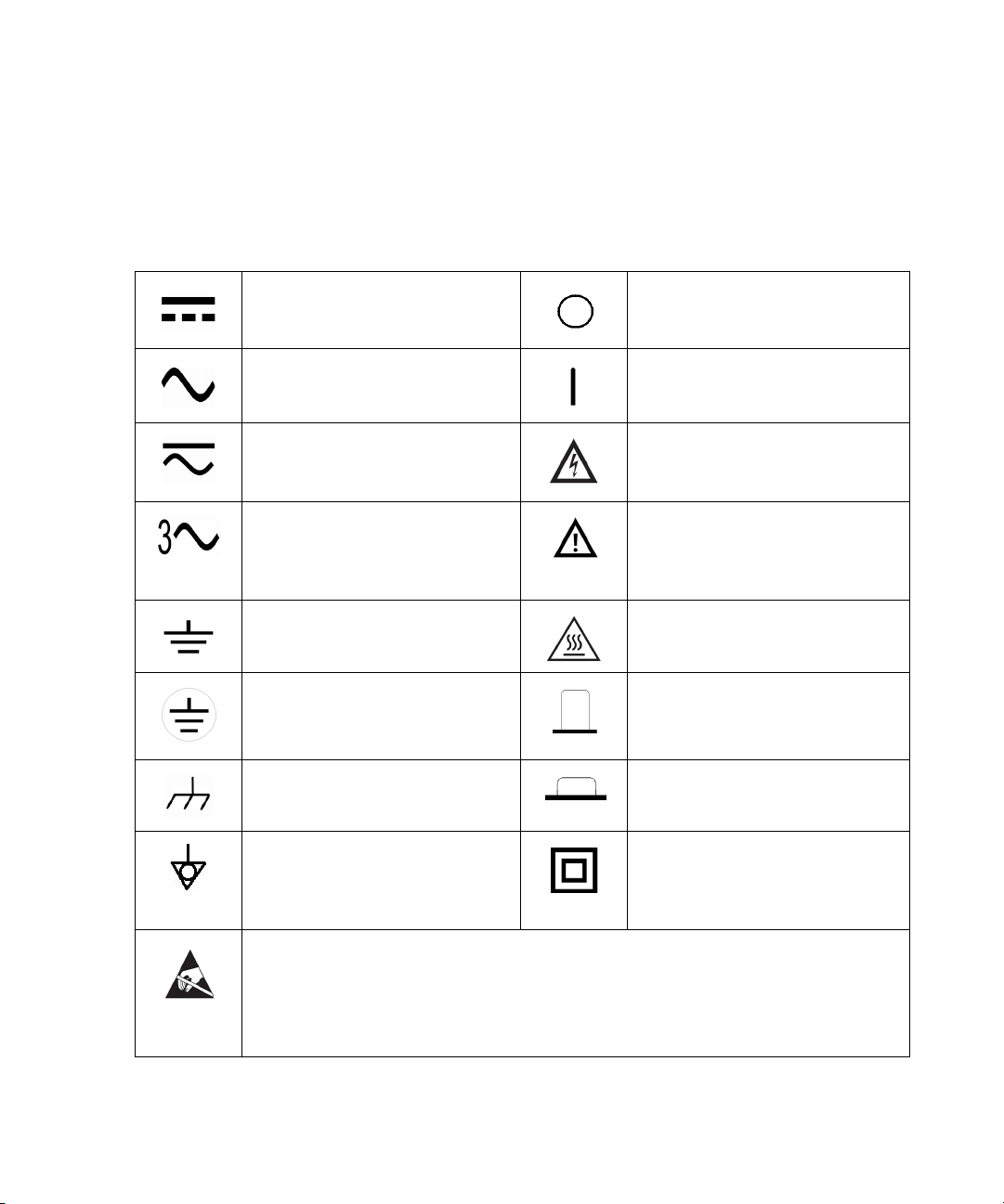
Safety Symbols
Direct current (DC) Off (supply)
Alternating current (AC) On (supply)
Both direct and alternating current Caution, risk of eletric shock
Three-phase alternating current Caution, risk of danger (refer to this
Earth (ground) terminal Caution, hot surface
Protective conductor terminal Out position of a bi-stable push control
The following symbol on the instrument and in the documentation
indicates precautions that must be taken to maintain safe operation of the
instrument.
manual for specific Warning or Caution
information)
Frame or chassis terminal In position of a bi-stable push control
Equipotentiality Equipment protected throughout by
double insulation or reinforced
insulation
This symbol indicates that a device, or part of a device, may be susceptible to electrostatic discharges
(ESD) which can result in damage to the product.
Observe ESD precautions given on the product, or its user documentation, when handling equipment
bearing this mark.
N8480 Series Power Sensors Operating and Service Guide iii
Page 4
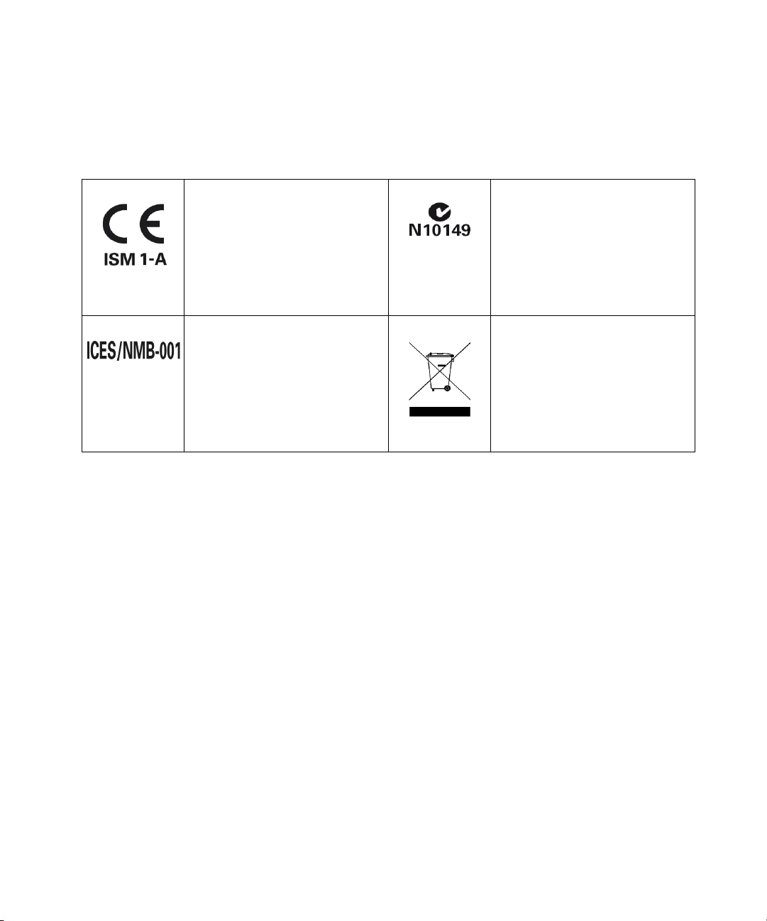
Regulatory Markings
The CE mark shows that the product
complies with all the relevant European legal Directives (if accompanied
by a year, it signifies when the design
was proven).
This ISM device complies with the
Canadian ICES-001,
Cet appareil ISM est conforme à la
norme NMB-001 du Canada.
The C-tick mark is a registered
trademark of the Spectrum
management Agency of Australia.
This signifies compliance with the
Australian EMC Framework
regulations under the terms of the
Radio Communications Act of 1992.
This product complies with the WEEE
Directive (2002/96/EC) marking
equipment. The affixed product label
indicates that you must not discard
this electrical/electronic product in
domestic household waste.
iv N8480 Series Power Sensors Operating and Service Guide
Page 5

General Safety Information
WARNING
CAUTION
The following general safety precautions must be observed during all
phases of operation, service, and repair of this instrument. Failure to
comply with these precautions or with specific warnings elsewhere in this
manual violates safety standards of design, manufacture, and intended
use of the instrument. Agilent Technologies assumes no liability for the
customer’s failure to comply with these requirements.
Before connecting the power sensor to other instruments ensure that all
instruments are connected to the protective (earth) ground. Any
interruption of the protective earth grounding will cause a potential
shock hazard that could result in personal injury.
• Use the instrument with the cables provided.
• Repair or service that is not covered in this manual should only be
performed by qualified personnels.
N8480 Series Power Sensors Operating and Service Guide v
Page 6
Waste Electrical and Electronic Equipment (WEEE) Directive
2002/96/EC
This instruction complies with the WEEE Directive (2002/96/EC) marking
requirement. This affixed product label indicates that you must not discard
this electrical/electronic product in domestic household waste.
Product Category:
With reference to the equipment types in the WEEE directive Annex 1, this
instrument is classified as a “Monitoring and Control Instrument” product.
The affixed product label is shown as below:
Do not dispose in domestic household waste
To return this unwanted instrument, contact your nearest Agilent office, or
visit
www.agilent.com/environment/product
for more information.
vi N8480 Series Power Sensors Operating and Service Guide
Page 7
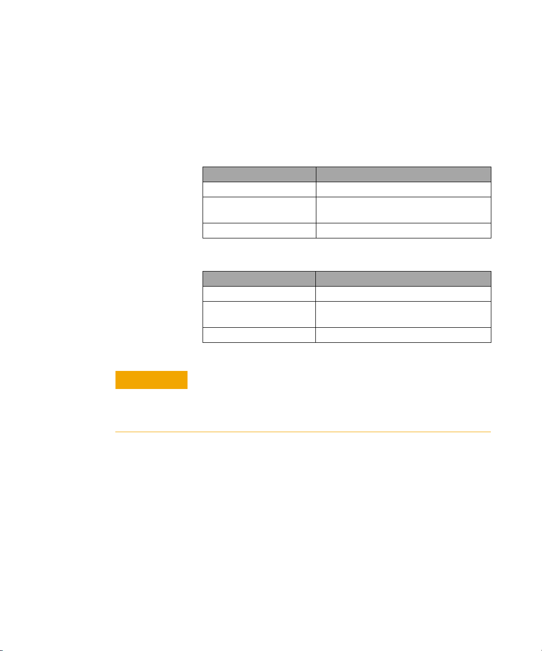
Environmental Conditions
CAUTION
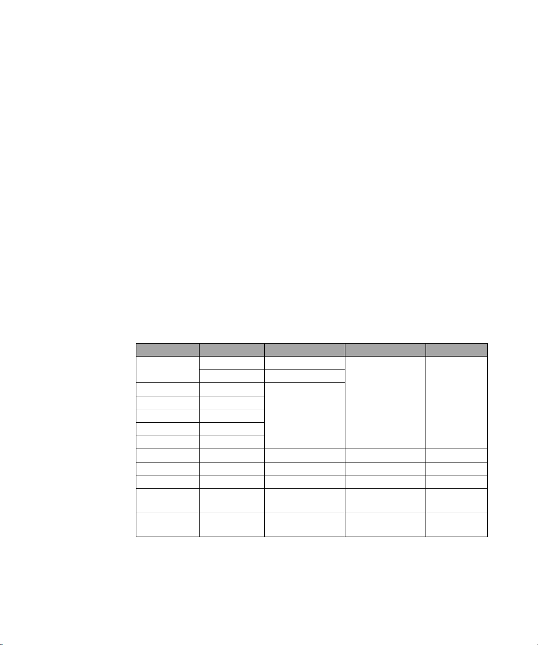
This instrument is designed for indoor use only. The table below shows
the general environmental requirements for the product.
Operating Environment
Environmental Conditions Requirements
Temperature 0 °C to 55 °C (Operating)
Humidity Maximum: 95% at 40 °C
Altitude Operating up to 4,600 metres (15,000 feet)
Storage Conditions
Environmental Conditions Requirements
Temperature –40 °C to 70 °C (Non-operating)
Humidity Non-operating up to 90% at 65 °C
Altitude Non-operating up to 7,620 metres (25,000 feet)
The N8480 Series power sensors complies with the following EMC
requirements:
• IEC 61326-1:2005/EN 61326-1:2006
• Canada: ICES/NMB-001:2004
• Australia/New Zealand: AS/NZS CISPR11:2004
Minimum: 15% at 40 °C
(Non-condensing)
N8480 Series Power Sensors Operating and Service Guide vii
Page 8

Declaration of Conformity (DoC)
NOTE
The Declaration of Conformity (DoC) for this instrument is available on the
Web site. You can search the DoC by its product model or description.
http://regulations.corporate.agilent.com/DoC/search.htm
If you are unable to search for the respective DoC, please contact your
local Agilent representative.
viii N8480 Series Power Sensors Operating and Service Guide
Page 9

In This Guide ...
1 Introduction Chapter 1 introduces the overview and operation of
the N8480 Series power sensors.
2 Specifications and Characteristics Chapter 2 describes the
specifications and characteristics of the N8480 Series power
sensors.
3Service Chapter 3 elaborates on the information about principle of
operations, troubleshooting, and repair of the N8480 Series power
sensors.
N8480 Series Power Sensors Operating and Service Guide ix
Page 10

x N8480 Series Power Sensors Operating and Service Guide
Page 11

Contents
Notices ii
Safety Symbols iii
Safety Symbols iii
Regulatory Markings iv
General Safety Information v
Waste Electrical and Electronic Equipment (WEEE) Directive 2002/96/EC vi
Environmental Conditions vii
In This Guide ... ix
1 Introduction
General Information 2
Initial Inspections 3
Accessories Shipped with the Instrument 3
Original Packaging 3
Power Meter and Sensor Cable Requirements 4
Interconnection and Calibration 5
Recommended Calibration Interval 6
Temperature Sensitivity 6
Operating Instructions 7
Modulation Effect 8
To r q u e 8
Overview of the N8480 Series Power Sensors 9
N8485A Power Sensor 12
N8487A Power Sensor 12
N8488A Power Sensor 13
B-models and H-models Information 13
Waveguide-models Information 14
Options 15
Power Meter Firmware Compatibility 16
Power Meter Configuration Changes 17
Measurement Accuracy and Speed 18
Measurement Considerations 18
N8480 Series Power Sensors Operating and Service Guide xi
Page 12

2 Specifications and Characteristics
Specification Definitions 20
Warranted Specifications 20
Characteristic Specifications 20
Conditions 21
Specifications 22
Frequency and Dynamic Power Range 22
Damage Level 23
Maximum SWR 24
Power Linearity 31
Switching Point 35
Zero Set, Zero Drift and Measurement Noise 36
Settling Time 37
Calibration Factor and Reflection Coefficient 38
Calibration Factor Uncertainty 39
Supplemental Characteristics 43
Physical Characteristics 44
3 Service
Cleaning 46
Connector Care 46
Principle of Operations 47
Performance Test 48
Standing Wave Ratio (SWR) and Reflection Coefficient (Rho) Performance Test 48
Replaceable Parts 51
Troubleshooting 57
Repair 57
Diassembly/Reassembly Procedures 58
Diassembly Procedure 58
Reassembly Procedure 58
xii N8480 Series Power Sensors Operating and Service Guide
Page 13

List of Figures
Figure 1-1 N8480 Series power sensors 2
Figure 1-2 Connecting a sensor cable to power meter 5
Figure 1-3 Connecting waveguide flange to the N8486AQ power sensor 7
Figure 1-4 N8480 Series power sensor simplified block diagram 11
Figure 1-5 N8485A power sensor with adapter 12
Figure 1-6 N8487A power sensor with adapter 12
Figure 1-7 N8488A power sensor with adapter 13
Figure 1-8 Auto-averaging settings 17
Figure 2-1 Typical SWR, 10 MHz to 18 GHz (25 °C ±10 °C) for N8481A power sensor 25
Figure 2-2 Typical SWR, 100 kHz to 6 GHz (25 °C ±10 °C) for N8482A power sensor 26
Figure 2-3 Typical SWR, 10 MHz to 26.5 GHz (25 °C ±10 °C) for N8485A power sensor 26
Figure 2-4 Typical SWR, 50 MHz to 50 GHz (25 °C ±10 °C) for N8487A power sensor 27
Figure 2-5 Typical SWR, 10 MHz to 70 GHz (25 °C ±10 °C) for N8488A power sensor 27
Figure 2-6 Typical SWR, 33 MHz to 50 GHz (25 °C ±10 °C) for N8486AQ power sensor 28
Figure 2-7 Typical SWR, 26.5 GHz to 40 GHz (25 °C ±10 °C) for N8486AR power sensor 28
Figure 2-8 Typical SWR, 10 MHz to 18 GHz (25 °C ±10 °C) for N8481B power sensor 29
Figure 2-9 Typical SWR, 100 kHz to 6 GHz (25 °C ±10 °C) for N8482B power sensor 29
Figure 2-10 Typical SWR, 10 MHz to 18 GHz (25 °C ±10 °C) for N8481H power sensor 30
Figure 2-11 Typical SWR, 100 kHz to 6 GHz (25 °C ±10 °C) for N8482H power sensor 30
Figure 2-12 Typical N8481/2/5/7/8A and N8486AR/AQ power linearity at 25 °C, after
zero and calibration with associated measurement uncertainty 32
Figure 2-13 Typical N8481/2B power linearity at 25 °C, after zero and calibration with
associated measurement uncertainty 33
Figure 2-14 Typical N8481/2H power linearity at 25 °C, after zero and calibration with
associated measurement uncertainty 34
Figure 2-15 Autofilter, default resolution, 10 dB decreasing power step (not across the
switching point) 37
Figure 2-16 Typical cal factor and SWR vs. frequency 43
Figure 3-1 Illustrated Parts Breakdown 52
Figure 3-2 Removing power sensor shell 58
N8480 Series Power Sensors Operating and Service Guide xiii
Page 14

xiv N8480 Series Power Sensors Operating and Service Guide
Page 15

List of Tables
Ta b l e 1 - 1 Power sensor cable options 4
Ta b l e 1 - 2 RF connector type, wrench size, and torque values 8
Ta b l e 1 - 3 Power range in range setting 10
Ta b l e 1 - 4 Power meter firmware 16
Ta b l e 2 - 1 Frequency and dynamic power range 22
Ta b l e 2 - 2 Damage level at average and peak power 23
Ta b l e 2 - 3 Maximum SWR 24
Ta b l e 2 - 4 Power linearity 31
Ta b l e 2 - 5 Switching point hysteresis 35
Ta b l e 2 - 6 Zero set, zero drift and measurement noise 36
Ta b l e 2 - 7 Settling time in normal and x2 mode 37
Ta b l e 2 - 8 Calibration factor uncertainty at 25 ºC ± 3 ºC 39
Ta b l e 2 - 9 Calibration factor uncertainty at 25 ºC ± 10 ºC 40
Ta b l e 2 - 1 0 Calibration factor uncertainty at 0 ºC to 55 ºC 42
Ta b l e 2 - 1 1 Physical dimensions 44
Ta b l e 3 - 1 Reflection coefficient for N8480 Series power sensors (25 ºC ± 10 ºC) 49
Ta b l e 3 - 2 Replaceable parts list for standard N8480 Series power sensors 53
Ta b l e 3 - 3 Replaceable parts list for N8480 Series power sensors with Option CFT 55
N8480 Series Power Sensors Operating and Service Guide xv
Page 16

xvi N8480 Series Power Sensors Operating and Service Guide
Page 17

N8480 Series Power Sensors
Operating and Service Guide
1 Introduction
General Information 2
Initial Inspections 3
Accessories Shipped with the Instrument 3
Original Packaging 3
Power Meter and Sensor Cable Requirements 4
Interconnection and Calibration 5
Recommended Calibration Interval 6
Temperature Sensitivity 6
Operating Instructions 7
Modulation Effect 8
To r q u e 8
Overview of the N8480 Series Power Sensors 9
N8485A Power Sensor 12
N8487A Power Sensor 12
N8488A Power Sensor 13
B-models and H-models Information 13
Waveguide-models Information 14
Options 15
Power Meter Firmware Compatibility 16
Power Meter Configuration Changes 17
Measurement Accuracy and Speed 18
This chapter contains information about initial inspection and overview of the Agilent
N8480 Series power sensors.
Agilent Technologies
1
Page 18
1 Introduction
General Information
This guide contains information about the initial inspection, connections,
specifications, operation, and performance tests of the N8480 Series power
sensors. You can also find a copy of this guide on the EPM and EPM- P
Series Power Meter Documentation CD supplied with the power meter.
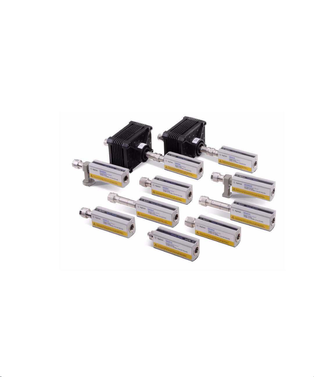
Figure 1-1 N8480 Series power sensors
2 N8480 Series Power Sensors Operating and Service Guide
Page 19

Introduction 1
NOTE
Initial Inspections
1 Inspect the shipping container for damage. Signs of damage may include
a dented or torn shipping container or cushioning material that shows
signs of unusual stress or compacting.
2 Carefully remove the contents from the shipping container and verify
that your order is complete.
• If the shipping container or packaging material is damaged, it should be kept until the
contents have been checked mechanically and electrically. If there is mechanical
damage, notify the nearest Agilent Technologies office. Keep the damaged shipping
materials (if any) for inspection by the carrier and Agilent representative. If required, you
can find a list of Agilent Sales and Service Offices on the last page of this guide.
• Ensure you have read and understand the preceding safety information before proceed.
Accessories Shipped with the Instrument
The following items are shipped with every purchase of N8480 Series
power sensor:
• Certificate of Calibration
• N8480 Series Power Sensors Operating and Service Guide
• Product Reference CD
Verify that any options ordered are included with the shipment by
checking the packing list included with the shipment.
Original Packaging
Containers and materials identical to those used in the factory packaging
are available through Agilent Technologies office. If the instrument is
being returned to Agilent Technologies for servicing, attach a tag
indicating the type of service required, return address, model number, and
serial number. Also mark the container FRAGILE to assure careful
handling. In any correspondence, refer to the instrument by model number
and serial number.
N8480 Series Power Sensors Operating and Service Guide 3
Page 20

1 Introduction
Power Meter and Sensor Cable Requirements
Table 1- 1 lists the length of cable option for the N8480 Series power
sensors.
Tab l e 1 - 1 Power sensor cable options
Power Sensor Cable Option Description Supported Power Meter
11730 Family Sensor Cables (Grey)
11730A 1.5 m (5-ft) cable length
11730B 3 m (10-ft) cable length
11730C 6.1 m (20-ft) cable length
11730D 15.2 m (50-ft) cable length
11730E
1
11730F
E9288 Family Sensor Cables (Blue)
E9288A 1.5 m (5-ft) cable length
E9288B 3 m (10-ft) cable length
E9288C 10 m (31-ft) cable length
N1917 Family Sensor Cable Adapter
N1917A 1.5 m (5-ft) cable length
N1917B 3 m (10-ft) cable length
N1917C 10 m (31-ft) cable length
1
Only applicable for E4418B and E4419B power meters.
30.5 m (100-ft) cable
length
61 m (200-ft) cable length
(operate up to 45 °C)
EPM Series power meters
EPM Series power meters
EPM-P Series power
meters
P-Series power meters
1
4 N8480 Series Power Sensors Operating and Service Guide
Page 21
Introduction 1
NOTE
CAUTION
WARNING
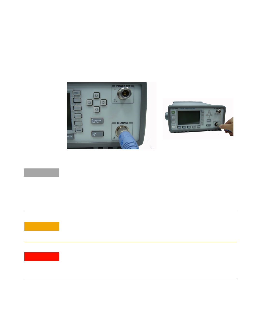
Interconnection and Calibration
Connect one end of the supported sensor cable to the N8480 Series power
sensor and connect the other end of the cable to the power meter’s
channel input. Allow approximately four seconds for the power meter to
download the data from the power sensor’s EEPROM.
Figure 1-2 Connecting a sensor cable to power meter
N8480 Series Power Sensors Operating and Service Guide 5
• For B-models power sensors, you must disconnect the attached attenuator before
connecting it to the power meter for zero and calibration.
• The waveguide-models power sensors have two inputs:
• Type-N connector — for a 50 MHz 1 mW calibration signal generated by the
power meter
• Waveguide flange — to be connected to the test port during actual measurement.
For power sensors with Type-N connector, connect the power sensor to the power
meter by turning the nut only. The power sensor can be damaged if the torque is
applied to the power sensor’s body.
Before connecting the power sensor to other instruments, ensure that all
instruments are connected to the protective (earth) ground. Any interruption of the
protective earth grounding will cause a potential shock hazard that could result in
personal injury.
Page 22

1 Introduction
To carry out a zero and calibration cycle required by the power meter,
refer to the respective power meter’s User’s Guide for details of the power
sensor’s zero and calibration procedures.
Recommended Calibration Interval
Agilent Technologies recommends a one year calibration cycle for the
N8480 Series power sensors.
Temperature Sensitivity
The sensitivity of the power sensor is influenced by ambient temperature.
The sensor should be recalibrated at each change in temperature to obtain
the most accurate results. The sensor has a built- in temperature
compensation that ensures the accuracy of measurement carried out
within 0 to 55 °C, refer to Table 2- 4 for details. For measurement below
–25 dBm, it is recommended to re- apply zero procedure when there has
been a temperature variation of more than ±5 °C since the last zeroing.
6 N8480 Series Power Sensors Operating and Service Guide
Page 23
Introduction 1
CAUTION
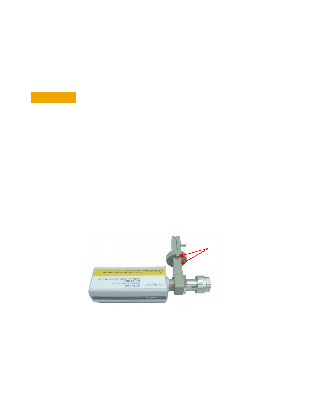
Insert this screw, and the
one opposite (hidden under
the instrument) as shown in
the diagram.
Operating Instructions
To operate the power sensors, refer to the operating instructions in the
respective power meter’s User’s Guide.
For N8486AQ power sensor only.
When connecting the waveguide flange to the power sensor, make sure you follow the
following procedures to avoid any damage to the precision waveguide flange:
1 Torque the waveguide flange’s screws to < 3.75 lb-in (maximum).
2 Insert the two screws as indicated in Figure 1-3 located at the side of the flange. Insert
the remaining two screws to either side of the flange. Tighten the four screws until
finger tight.
3 Tighten the flange using a calibrated torque wrench by going back and forth between
each screws that are opposite to each others. Tighten each screw with a small
incremental torque until the desired torque is achieved.
If you are using the hex ball driver, hold the driver with your thumb and forefinger to
avoid excess torque. You must extremely carefull not to over-torque when using the hex
ball driver, and do not fully torque one screw before tightening the others.
N8480 Series Power Sensors Operating and Service Guide 7
Figure 1-3 Connecting waveguide flange to the N8486AQ power sensor
Page 24
1 Introduction
Modulation Effect
When measuring RF or microwave sources that are modulated at the
chopper frequency (nominally 440 Hz), at the first or second harmonic or
submultiples of the chopper frequency, beat notes may occur. Unless these
beat notes are exactly the chopper frequency, they can usually be
eliminated by averaging (filtering) since the amplitudes are plus and
minus the actual power. These frequencies may also be avoided by
changing the modulation frequency slightly, if possible.
Refer to the respective power meter’s User’s Guide for information on
setting the averaging (filtering).
Torque
Table 1- 2 shows the connector type (for connection to DUT) for the power
sensor models. A torque wrench must be used to tighten these connectors.
Only use a wrench set to the correct torque value.
Tab l e 1 - 2 RF connector type, wrench size, and torque values
Model Option RF Connector Wrench Size Torque Value
N8481A
N8482A
N8481B N8481B-100
N8482B N8482B-100
N8481H N8481H-100
N8482H N8482H-100
N8485A
N8487A N8487A-100 2.4 mm (male) 5/16 inch open end 8 lb-in
N8488A N8488A-100 1.85 mm (male) 4/5 inch open end 8 lb-in
N8486AQ N8486AQ-100
N8486AR N8486AR-100
1
Balldriver is used to tighten the screws, instead of the connector.
N8481A-100 Type-N (male)
N8481A-200 APC-7
N8482A-100
Type-N (male)
3/4 inch open end 12 lb-in
N8485A-100 3.5 mm (male) 3/4 inch open end 8 lb-in
Waveguide Flange
UG-383/U
Waveguide flange
UG-599/U
3/32 inch
Balldriver-Hex
3/32 inch
Balldriver-Hex
1
1
3.75 lb-in
3.75 lb-in
8 N8480 Series Power Sensors Operating and Service Guide
Page 25

Overview of the N8480 Series Power Sensors
The N8480 Series power sensors are high accuracy thermocouple power
sensors that allow direct measurement of RF or microwave power through
the heating effect it has on a terminating load. All calibration data for the
N8480 Series power sensors is stored in EEPROM
the power meter when the sensor is connected. In terms of functionality
and performance, they
thermocouple power sensors.
The N8480 Series power sensors are used for measuring the average power
supplied by an RF or microwave source or a device-under-test (DUT). In
use, the power sensor is connected to the RF or microwave source and to
a compatible power meter. The N8480 Series power sensors are compatible
with the EPM Series power meters (E4418B, E4419B, N1913A, and
N1914A), EPM- P Series power meters (E4416A and E4417A), and P- Series
power meters (N1911A and N1912A) only. The N8480 Series power sensors
place a 50 W load on the RF or microwave source. The power meter
indicates the power dissipated in this load in mW or dBm.
The N8480 Series power sensors consist of four sensor model types with
respective power range:
• A- models (–35 dBm to +20 dBm)
• N8481A, N8482A, N8485A, N8487A, and N8488A
• B- models (–5 dBm to +44 dBm)
• N8481B and N8482B
• H- models (–15 dBm to +35 dBm)
• N8481H and N8482H
• Waveguide- models (–35 dBm to +20 dBm)
• N8486AQ and N8486AR
2
replace and surpass the popular 8480
Introduction 1
1
and is downloaded to
3
1
The calibration factor table stored in the EEPROM is not applicable for N8480 Series sensors with
Option CFT.
2
Except for N8488A power sensor. N8488A power sensor is a newly introduced high frequency
sensor. It is not meant to replace any of the the existing 8480 thermocouple power sensors.
3
Option CFT is not available for N8488A power sensor.
N8480 Series Power Sensors Operating and Service Guide 9
Page 26

1 Introduction
NOTE
For B-models power sensors, the calibration factor data is valid only when the sensor is
used with the supplied attenuator.
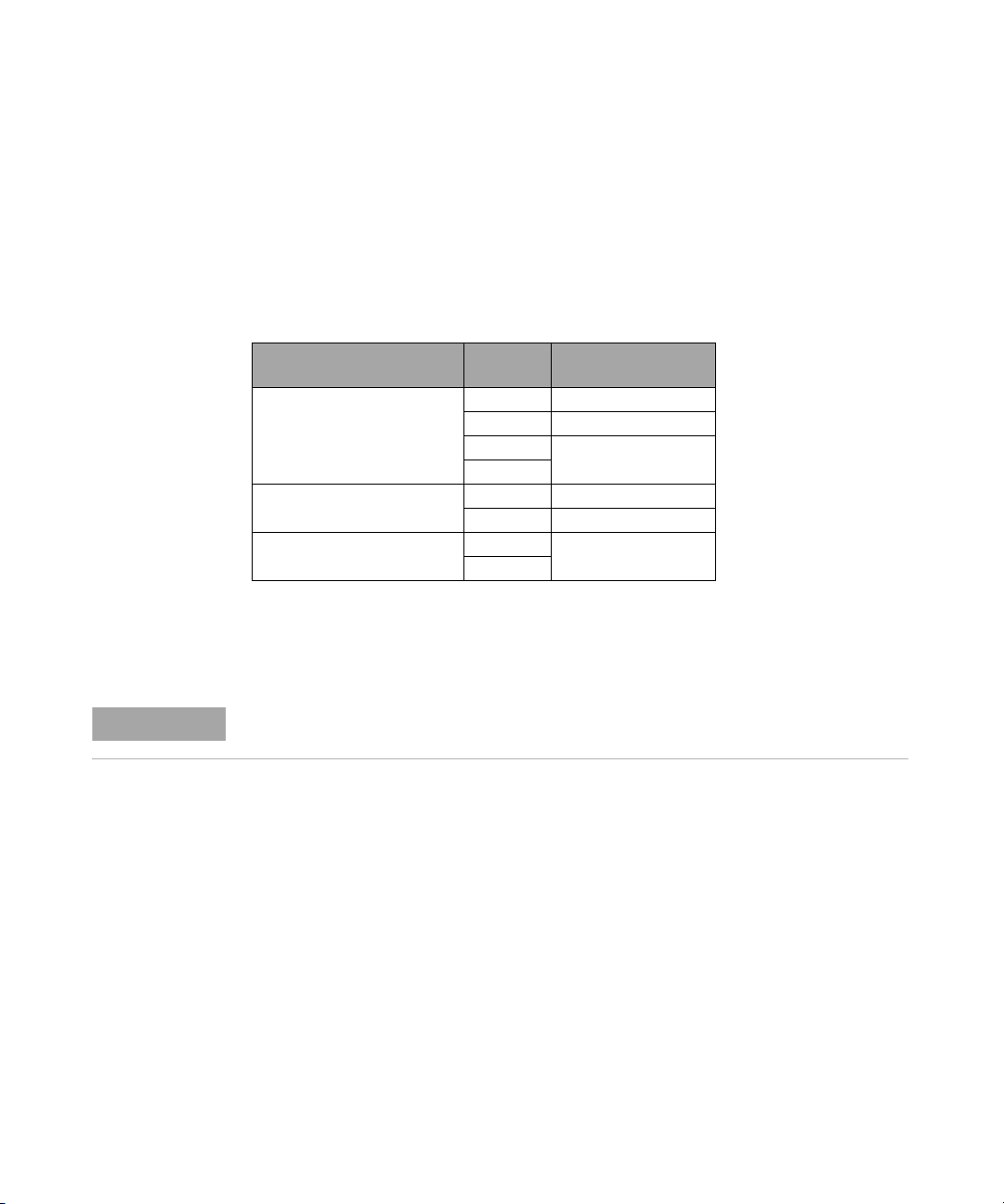
Tab l e 1 - 3 Power range in range setting
Sensor Range Setting Lower Range Upper Range
N8481/2/5/7/8A
and N8486AQ/AR
excluding Option
CFT
N8481/2B excluding
Option CFT
N8481/2H excluding
Option CFT
1
Recommended for pulse signals measurement with period of more than one second.
AUTO (Default) –35 dBm to –1 dBm
LOWER
1
UPPER
AUTO (Default) –5 dBm to +29 dBm
LOWER
1
UPPER
AUTO (Default) –15 dBm to +17 dBm
LOWER
1
UPPER
–35 dBm to –1 dBm
-
–5 dBm to +29 dBm
-
–15 dBm to +17 dBm
-
–1 dBm to +20 dBm
-
–30 dBm to +20 dBm
+29 dBm to +44 dBm
-
0 dBm to +44 dBm
+17 dBm to +35 dBm
-
–10 dBm to +35 dBm
The N8480 Series power sensors (excluding Option CFT) measure power
levels from –35 dBm to +44 dBm (316 nW to 25.1 W), at frequencies from
100 kHz to 67 GHz and have two independent power measurement range
(upper and lower range).
Meanwhile, the N8480 sensors with Option CFT (except for N8488A) only
measure power levels from –30 dBm to +44 dBm (1 µW to 25.1 W) in
single range. Similiar to the E- Series power sensors, the N8480 Series
power sensors are also equipped with EEPROM to store sensor’s
characteristics such as model number, serial number, linearity, temperature
compensation, calibration factor, and so forth.
This feature ensures the correct calibration data is applied by any
compatible power meter connected with N8480 Series power sensor, and
to ensure the accuracy of the measurements.
10 N8480 Series Power Sensors Operating and Service Guide
Page 27
Introduction 1
Thermocouple
Sensor
Thermistor
440 Hz
Gain-select
Circuit
Amplifier
Power Supply
I2C Remote I/O I2C Buffer Circuit
EEPROM
Chopper
RF Power
Pre-amplifier
To Power Meter via Power Sensor Cable
Reference Source
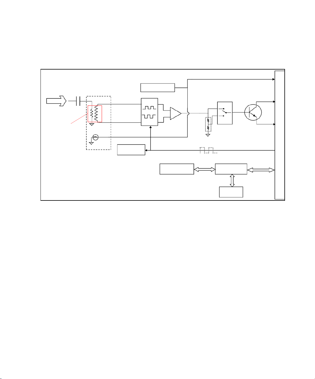
Figure 1-4 N8480 Series power sensor simplified block diagram
Figure 1- 4 illustrates a basic power sensor block diagram for
thermocouple power sensing elements. From the RF or microwave signal
input, the thermocouple detector mounts generate a very low voltage — in
the order of nV. As the DC voltage is very low, it requires amplification
before it can be transferred to the power meter on the standard cables.
The amplification is provided by an input amplifier assembly that consists
of a balanced chopper and an AC coupled low- noise amplifier. The DC
voltage is routed through gold wires to the chopper circuit, which converts
the low- level DC voltage to an AC voltage. To do this, the chopper is
controlled by a 440 Hz square- wave generated by the power meter (the
chop signal). The result is an AC output signal proportional to the DC
input. The AC signal is then amplified to a relatively high-level AC signal
that can be routed to the power meter by standard cables (Agilent 11730
Series cables are available up to 61 metres from –5 °C to 45 °C).
N8480 Series Power Sensors Operating and Service Guide 11
Page 28

1 Introduction
NOTE
NOTE
N8485A Power Sensor
The N8485A power sensor is fitted with 3.5 mm (m) connectors as
standard. To convert the 3.5 mm (m) connector for calibration, an adapter
(3.5 mm (f) to Type- N (m)) is included with the power sensor.
See Figure 1-5.
Figure 1-5 N8485A power sensor with adapter
The 3.5 mm to Type-N adapter is intended for the use of 1 mW, 50 MHz power reference of
the power meter only. Its function as a calibration reference may be compromised if it is
used for other purpose.
N8487A Power Sensor
The N8487A power sensor is fitted with 2.4 mm (m) connector as
standard. To convert the 2.4 mm (m) connector for calibration, an adapter
(2.4 mm (f) to Type- N (m)) is included with the power sensor.
See Figure 1-6.
Figure 1-6 N8487A power sensor with adapter
The 2.4 mm to Type-N adapter is intended for the use of 1 mW, 50 MHz power reference of
the power meter only. Its function as a calibration reference may be compromised if it is
used for other purpose.
12 N8480 Series Power Sensors Operating and Service Guide
Page 29

Introduction 1
NOTE
N8488A Power Sensor
The N8488A power sensor is calibrated to measure power levels in 10 MHz
to 67 GHz frequency range. This sensor is functional up to 70 GHz; with
typical specifications ranging from 67 GHz to 70 GHz.
The N8488A power sensor is fitted with 1.85 mm (m) connector as
standard. To convert the 1.85 mm (m) connector for calibration, an
adapter (2.4 mm (f) to Type- N (m)) is included with the power sensor.
See Figure 1-7.
Figure 1-7 N8488A power sensor with adapter
• The 2.4 mm to Type-N adapter is intended for the use of 1 mW, 50 MHz power reference
of the power meter only. Its function as a calibration reference may be compromised if it
is used for other purpose.
• According to IEEE Standard for Precision Coaxial 1.85 mm Slash Sheet, the 1.85 mm (m)
connector is compatible with the 2.4 mm (f) connector. Hence, the adapter (2.4 mm (f) to
Type-N (m)) can be used to convert the 1.85 mm (m) connector for calibration.
B-models and H-models Information
The B- models (with 30 dB removable attenuator) or H- models (with 20 dB
attenuator) power sensor is a calibrated combination of an attenuator
assembly and a sensor assembly.
The attenuator and sensor assemblies are calibrated as a set and must be
used together when a specified accuracies are to be obtained. These
combination is referred to as a power sensor.
N8480 Series Power Sensors Operating and Service Guide 13
Page 30

1 Introduction
NOTE
WARNING
For B-models power sensors only
• Removal of D-ring from the sensor assembly will void the warranty.
• The D-ring that is available on the input connector; located on the sensor is used to
prevent the sensor from being connected to a high power source when an attenuator is
not attached. The sensors must only be connected to the power meter for calibration or
to a high power attenuator for any RF measurements.
• For B-models power sensors only. The high power attenuator contains a substrate
of beryllium oxide. Beryllium oxide in powder form ia a hazardous material and
may be harmful to your health if inhaled. Do not perform any operation on the
beryllium oxide that might generate dust.
• Defective attenuator should be returned to Agilent Technologies for proper
disposal.
Waveguide-models Information
14 N8480 Series Power Sensors Operating and Service Guide
The waveguide power sensors (excluding Option CFT) measure power
levels from –35 dBm to +20 dBm at frequencies from 26.5 GHz to 50 GHz.
They consist of a multi- stepped coax which adapt the 50 W thermocouple
impedance to the desired waveguide impedance, and hence provide a very
low SWR up to 40 or 50 GHz.
Page 31

Introduction 1
NOTE
NOTE
Options
N8481A Option 200
The N8481A power sensor is fitted with Type- N (m) connector as
standard. Users can choose the sensor to be fitted with APC- 7 connector
by choosing the Option 200.
N8485A Option 033
The N8485A power sensor with Option 033 is calibrated to measure power
levels in the 10 MHz to 33 GHz frequency range.
The N8485A Option 033 power sensor is fitted with a 3.5 mm(m) connector.
N8480 Series power sensors with Option CFT
The N8480 Series power sensors with Option CFT covers –30 dBm to
+20 dBm in a single power range and allows users to use the calibration
factor in two methods:
• manually enter the calibration factor for a particular frequency prior to
make a measurement; or
• manually enter the sensors calibration factor table and select the
frequency of the signal to be measured
The calibration factor data is provided on the label attached to the power
sensor’s cover. This calibration factor is used to make frequency
dependent efficiency correction and it is unique to each sensors.
For Option CFT specifications and characteristics, see
Chapter 2, “Specifications and Characteristics.”
• The calibration factor table stored in the EEPROM is not applicable for N8480 Series power
sensors with Option CFT.
• Please refer to the respective power meter’s User’s Guide on how to make a measurement using
the calibration factor table.
N8480 Series Power Sensors Operating and Service Guide 15
Page 32
1 Introduction
NOTE
Power Meter Firmware Compatibility
Before using the N8480 Series power sensors, make sure the power meter
is using the latest firmware as shown in Table 1- 4. This is to ensure that
the power meter is compatible with N8480 Series power sensors.
Tab l e 1 - 4 Power meter firmware
Power Meter
EPM Series power meters
EPM-P Series power meters
P-Series power meters
Model
Number
E4418B A1.09.01 and above
E4419B A2.09.01 and above
N1913A
N1914A
E4416A A1.05.01 and above
E4417A A2.05.01 and above
N1911A
N1912A
Compatible
Firmware Revision
A.01.00 and above
A.05.02 and above
For detailed information on the firmware installation, refer to the
respective power meter Web site located at www.agilent.com under
Technical Support > Drivers & Software > Firmware Update.
You can also find the compatible power meter’s firmware as well as the firmware upgrade
procedures in N8480 Series Power Sensors Product Reference CD.
16 N8480 Series Power Sensors Operating and Service Guide
Page 33
Power Meter Configuration Changes
Sensor Power
Minimum
Sensor Dynamic Range
1234
1128
Resolution Setting
Number of Averages
22432
2
4
32
2 2 16 256
2 8 128 128
Maximum
4 64 256 512
Upper Range
Lower Range
Sensor Power
0 dBm
–1 dBm
–30 dBm
–10 dBm
–20 dBm
2
20 dBm
17 dBm
–10 dBm
10 dBm
0 dBm
N8481/2H
30 dBm
29 dBm
0 dBm
20 dBm
10 dBm
N8481/2B
N8481/2/5/7/8A
N8486AQ/AR
NOTE
The Agilent EPM Series, EPM- P Series, or P- Series power meters recognize
the Agilent N8480 Series power sensor when it is connected. The N8480
Series power sensors (excluding Option CFT) calibration data is
automatically read by the power meter. In addition, the auto- averaging
settings shown in Figure 1-8 are also automatically configured.
Introduction 1
Figure 1-8 Auto-averaging settings
These values are valid only for the power meter channel connected to an Agilent N8480
N8480 Series Power Sensors Operating and Service Guide 17
Series power sensor. Averaging settings can also be manually configured. Refer to the
respective power meter’s User’s Guide for information on setting the averaging (filtering).
Page 34

1 Introduction
Measurement Accuracy and Speed
The power meter has no internal ranges. The only ranges you can set are
those of the Agilent N8480 Series power sensors and other Agilent
E- Series power sensors. With an Agilent N8480 Series power sensor
(excluding Option CFT) or E- Series power sensor, the range can be set
either automatically or manually. Use autoranging when you are not sure
of the power level you are about to measure.
Measurement Considerations
While autoranging is a good starting point, it is not ideal for all
measurements. Signal characteristics such as crest factor or duty cycle
may cause the power meter to select a range which is not the optimum
configuration for your specific measurement needs. Signals with average
power levels close to the range switch point require you to consider your
needs for measurement accuracy. When measuring pulse signals, you are
recommended to select manual filtering. This allows you to choose the
averaging to cover the many periods of the pulse signal instead of having
it determined by measurement noise. Selecting manual filtering also
changes the behaviour of the autoranging to help prevent frequency range
changes due to pulses. For a very long pulse periods (more than one
second), it may be better to select UPPER range as this will prevent any
possibility of range changes upsetting the measurement.
18 N8480 Series Power Sensors Operating and Service Guide
Page 35

N8480 Series Power Sensors
Operating and Service Guide
2 Specifications and Characteristics
Specification Definitions 20
Warranted Specifications 20
Characteristic Specifications 20
Conditions 21
Specifications 22
Frequency and Dynamic Power Range 22
Damage Level 23
Maximum SWR 24
Power Linearity 31
Switching Point 35
Zero Set, Zero Drift and Measurement Noise 36
Settling Time 37
Calibration Factor and Reflection Coefficient 38
Calibration Factor Uncertainty 39
Supplemental Characteristics 43
Physical Characteristics 44
This chapter contains information about specifications and characteristics of the Agilent
N8480 Series power sensors.
Agilent Technologies
19
Page 36

2 Specifications and Characteristics
Specification Definitions
There are two types of product specifications:
• warranted specifications
• characteristic specifications
Warranted Specifications
Warranted specifications are covered by the product warranty and apply
over 0 °C to 55 °C, unless otherwise noted. Warranted specifications
include measurement uncertainty calculated with 95% confidence.
Characteristic Specifications
Characteristic specifications are not warranted. They describe product
performance that is useful in the application of the power sensors by
giving typical, but non- warranted performance parameters. These
characteristics are shown in italics or denoted as “typical”, “nominal” or
“approximate”.
Characteristic information is representative of the product. In many
cases, it may also be supplemental to a warranted specification.
Characteristic specifications are not verified on all power sensors. The
types of characteristic specifications can be placed in two groups:
• The first group of characteristic types describes 'attributes' common to
all products of a given model or option.
Examples of characteristics that describe 'attributes' are product weight,
and 50 W input Type- N connector. In these examples product weight is
an approximate value and a 50 W input is nominal. These two terms
are most widely used when describing a product's 'attributes'.
20 N8480 Series Power Sensors Operating and Service Guide
Page 37

Specifications and Characteristics 2
• The second group of characteristic types describes 'statistically' the
aggregate performance of the population of products. These
characteristics describe the expected behavior of the population of
products. They do not guarantee the performance of any individual
product. No measurement uncertainty value is accounted for in the
specification. These specifications are referred to as typical.
Conditions
The power meter and power sensor meet its specifications when:
• Stored for a minimum of two hours at a stable temperature within the
operating temperature range, and turned on for at least 30 minutes.
• The power meter and power sensor are within their recommended
calibration periods.
• Used in accordance to the information provided in the power meter’s
User's Guide.
N8480 Series Power Sensors Operating and Service Guide 21
Page 38

2 Specifications and Characteristics
NOTE
Specifications
• Specifications stated in this chapter refer to all N8480 Series power sensors unless
otherwise stated.
• The term “standard” used in table under the Sensor Option column is refering to all
N8480 Series power sensors except Option CFT.
Frequency and Dynamic Power Range
Tab l e 2 - 1 Frequency and dynamic power range
Sensor Option Sensor Model Frequency Range Dynamic Power Range
Standard
N8481A 10 MHz to 18 GHz
N8482A 100 kHz to 6 GHz
N8485A 10 MHz to 26.5 GHz
N8485A Option 033 10 MHz to 33 GHz
N8487A 50 MHz to 50 GHz
N8488A
N8486AR 26.5 GHz to 40 GHz
N8486AQ 33 GHz to 50 GHz
N8481B 10 MHz to 18 GHz
N8482B 100 kHz to 6 GHz
N8481H 10 MHz to 18 GHz
N8482H 100 kHz to 6 GHz
10 MHz to 67 GHz
67 GHz to 70 GHz
–35 dBm to +20 dBm
–5 dBm to +44 dBm
–15 dBm to +35 dBm
22 N8480 Series Power Sensors Operating and Service Guide
Page 39
Specifications and Characteristics 2
Tab l e 2 -1 Frequency and dynamic power range
Sensor Option Sensor Model Frequency Range Dynamic Power Range
N8481A 10 MHz to 18 GHz
N8482A 100 kHz to 6 GHz
N8485A 10 MHz to 26.5 GHz
–30 dBm to +20 dBm
0 dBm to +44 dBm
–10 dBm to +35 dBm
Option CFT
N8485A Option 033 10 MHz to 33 GHz
N8487A 50 MHz to 50 GHz
N8486AR 26.5 GHz to 40 GHz
N8486AQ 33 GHz to 50 GHz
N8481B 10 MHz to 18 GHz
N8482B 100 kHz to 6 GHz
N8481H 10 MHz to 18 GHz
N8482H 100 kHz to 6 GHz
Damage Level
Tab l e 2 -2 Damage level at average and peak power
Sensor Model
N8481A
N8482A
N8485A
N8487A
N8488A
N8486AR
N8486AQ
N8481B
N8482B
N8481H
N8482H
Damage Level
(Average Power)
+25 dBm 15 W/2 µs
+49 dBm 500 W/1 µs
+40 dBm 100 W/1 µs
Damage Level
(Peak Power)
N8480 Series Power Sensors Operating and Service Guide 23
Page 40

2 Specifications and Characteristics
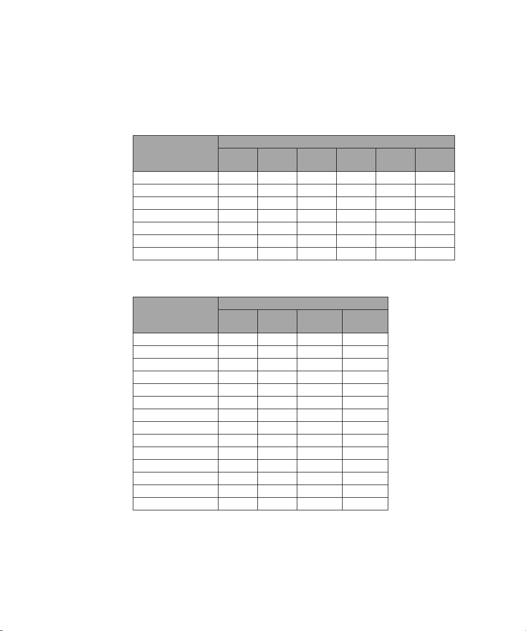
Maximum SWR
Tab l e 2 -3 Maximum SWR
Sensor Model Frequency Band
10 MHz to 30 MHz
30 MHz to 50 MHz
N8481A
N8482A
N8485A
N8487A
N8488A
50 MHz to 2 GHz
2 GHz to 12.4 GHz
12.4 GHz to 18 GHz
100 kHz to 300 kHz
300 kHz to 1 MHz
1 MHz to 2 GHz
2 GHz to 6 GHz
10 MHz to 50 MHz
50 MHz to 100 MHz
100 MHz to 2 GHz
2 GHz to 12.4 GHz
12.4 GHz to 18 GHz
18 GHz to 26.5 GHz
26.5 GHz to 33 GHz
50 MHz to 100 MHz
100 MHz to 2 GHz
2 GHz to 12.4 GHz
12.4 GHz to 18 GHz
18 GHz to 26.5 GHz
26.5 GHz to 40 GHz
40 GHz to 50 GHz
10 MHz to 100 MHz
100 MHz to 2.4 GHz
2.4 GHz to 12.4 GHz
12.4 GHz to 18 GHz
18 GHz to 26.5 GHz
26.5 GHz to 40 GHz
40 GHz to 67 GHz
67 GHz to 70 GHz
Maximum SWR
(25 °C ± 10 °C ) (0 °C to 55 °C )
1.37
1.14
1.08
1.16
1.23
1.54
1.17
1.06
1.07
1.33
1.08
1.05
1.14
1.19
1
1.26
1.32
1.08
1.05
1.10
1.16
1.22
1.30
1.34
1.08
1.08
1.10
1.12
1.21
1.30
1.46
1.48
1.57
1.16
1.11
1.16
1.25
1.57
1.17
1.06
1.08
1.53
1.11
1.07
1.14
1.20
1.28
1.36
1.10
1.07
1.10
1.16
1.22
1.30
1.33
1.08
1.08
1.10
1.14
1.23
1.31
1.47
1.50
24 N8480 Series Power Sensors Operating and Service Guide
Page 41
Tab l e 2 - 3 Maximum SWR
Frequency (GHz)
SWR
1
0
2
8
6
4
10
12
14
16
18
1.02
1.04
1.06
1.08
1.10
1.12
1.14
1.16
1.18
1.20
Specifications and Characteristics 2
Sensor Model Frequency Band
2
N8486AR
N8486AQ
50 MHz
26.5 GHz to 40 GHz
2
50 MHz
33 GHz to 50 GHz
10 MHz to 2 GHz
N8481B
2 GHz to 12.4 GHz
12.4 GHz to 18 GHz
N8482B
100 kHz to 2 GHz
2 GHz to 6 GHz
10 MHz to 8 GHz
N8481H
8 GHz to 12.4 GHz
12.4 GHz to 18 GHz
(25 °C ± 10 °C ) (0 °C to 55 °C )
Maximum SWR
1.17
1.40
1.17
1.50
1.09
1.14
1.23
1.08
1.16
1.16
1.22
1.32
1.20
1.40
1.20
1.50
1.10
1.18
1.28
1.10
1.18
1.16
1.22
1.41
N8482H 100 kHz to 6 GHz 1.13 1.14
1
Only applicable for N8485A Option 033.
2
SWR for 50 MHz calibration port . Type-N (m) coaxial connector is used in the 50 MHz calibration.
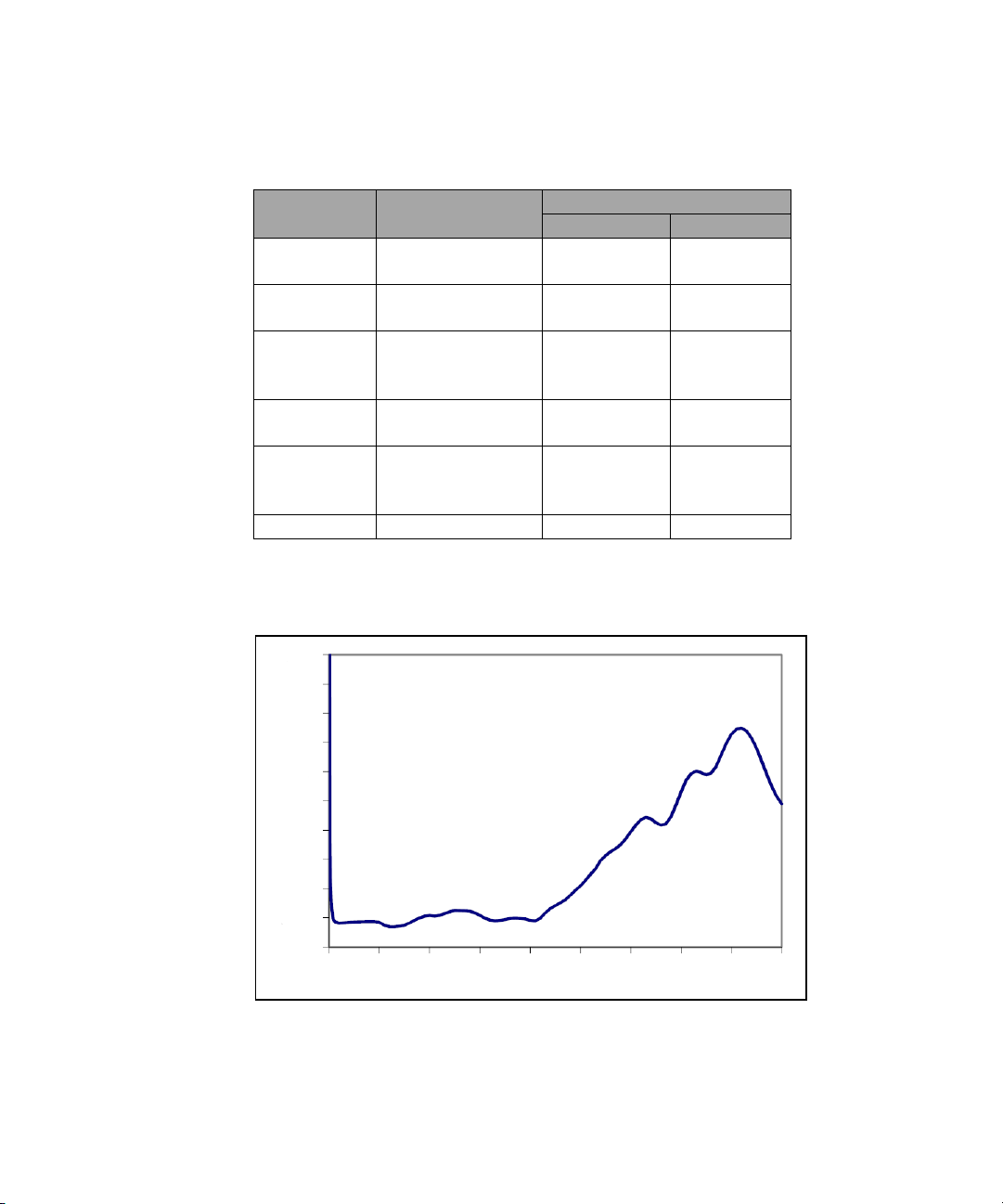
Figure 2-1 Typical SWR, 10 MHz to 18 GHz (25 °C ±10 °C) for N8481A power sensor
N8480 Series Power Sensors Operating and Service Guide 25
Page 42

2 Specifications and Characteristics
02
1
3
4
56
1
1.01
1.02
1.03
Frequency (GHz)
SWR
1.04
Frequency (GHz)
SWR
1
0
5
20
10
25
30
35
1.02
1.04
1.06
1.08
1.12
1.14
1.16
1.18
1.20
15
1.10
Figure 2-2 Typical SWR, 100 kHz to 6 GHz (25 °C ±10 °C) for N8482A power sensor
26 N8480 Series Power Sensors Operating and Service Guide
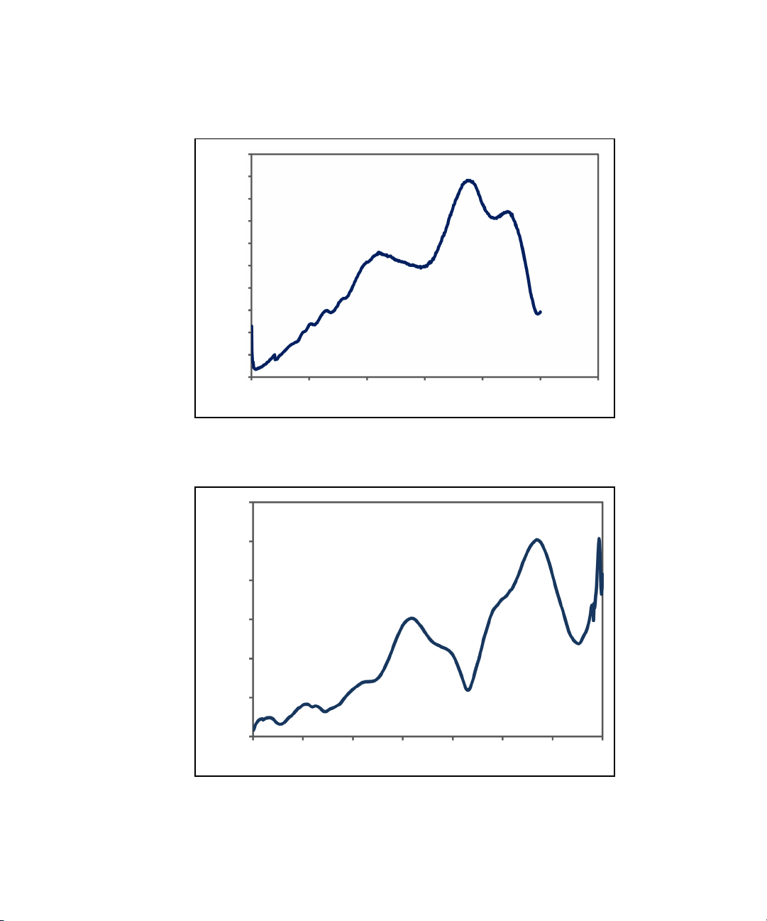
Figure 2-3 Typical SWR, 10 MHz to 26.5 GHz (25 °C ±10 °C) for N8485A power sensor
Page 43
Specifications and Characteristics 2
Frequency (GHz)
SWR
1
0
10
20
40
50
60
1.02
1.04
1.06
1.08
1.12
1.14
1.16
1.18
1.20
30
1.10
Frequency (GHz)
SWR
1
0
10
20
40
50
60
1.05
1.10
1.20
1.25
1.30
30
1.15
70
Figure 2-4 Typical SWR, 50 MHz to 50 GHz (25 °C ±10 °C) for N8487A power sensor
Figure 2-5 Typical SWR, 10 MHz to 70 GHz (25 °C ±10 °C) for N8488A power sensor
N8480 Series Power Sensors Operating and Service Guide 27
Page 44

2 Specifications and Characteristics
Frequency (GHz)
SWR
33
36
39
45
48
51
1.06
1.11
1.16
1.21
1.26
1.31
1.36
1.41
42
Frequency (GHz)
SWR
1.04
26.5
29
36.5
31.5
39
41.5
1.06
1.08
1.10
1.12
1.18
1.20
1.22
34
1.14
1.16
Figure 2-6 Typical SWR, 33 MHz to 50 GHz (25 °C ±10 °C) for N8486AQ power sensor
Figure 2-7 Typical SWR, 26.5 GHz to 40 GHz (25 °C ±10 °C) for N8486AR power sensor
28 N8480 Series Power Sensors Operating and Service Guide
Page 45

Specifications and Characteristics 2
Frequency (GHz)
SWR
1
0
2
8
4
10
12
14
1.01
1.02
1.03
1.04
1.06
1.07
1.08
6
1.05
16
18
20
Frequency (GHz)
SWR
1.01
0
1
4
2
5
6
7
1.012
1.014
1.016
1.018
1.022
1.024
1.026
1.028
3
1.020
Figure 2-8 Typical SWR, 10 MHz to 18 GHz (25 °C ±10 °C) for N8481B power sensor
Figure 2-9 Typical SWR, 100 kHz to 6 GHz (25 °C ±10 °C) for N8482B power sensor
N8480 Series Power Sensors Operating and Service Guide 29
Page 46

2 Specifications and Characteristics
Frequency (GHz)
SWR
0
2
8
4
10
12
14
6
16
18 20
1
1.02
1.04
1.06
1.08
1.20
1.22
1.24
1.18
1.16
1.14
1.12
1.10
Frequency (GHz)
SWR
1
1.01
1.02
1.03
1.04
1.06
1.07
1.08
1.09
1.05
0
1
4
2
5
6
3
7
Figure 2-10 Typical SWR, 10 MHz to 18 GHz (25 °C ±10 °C) for N8481H power sensor
Figure 2-11 Typical SWR, 100 kHz to 6 GHz (25 °C ±10 °C) for N8482H power sensor
30 N8480 Series Power Sensors Operating and Service Guide
Page 47

Specifications and Characteristics 2
NOTE
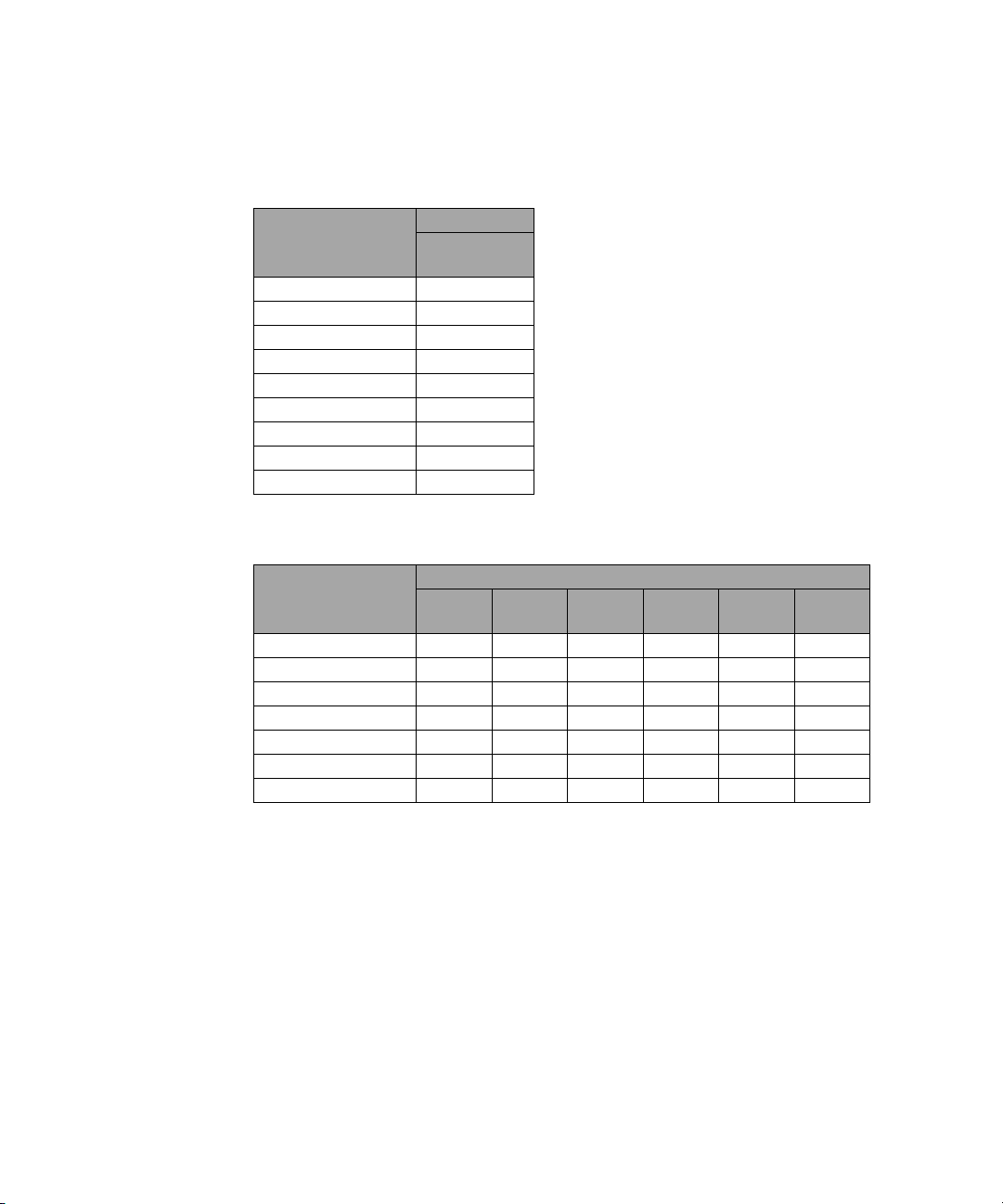
Power Linearity
After zero and calibration at ambient environment conditions.
The N8480 Series power sensors’ linearity is negligible except for the power range
specified in Ta b l e 2 - 4 .
Tab l e 2 - 4 Power linearity
Sensor Model Power Range
N8481A
N8482A
N8485A
N8487A
N8488A
N8486AR
N8486AQ
N8481B
N8482B
N8481H
N8482H
–1 dBm to +15 dBm ±0.52% ±0.80%
+15 dBm to +20 dBm ±0.80% ±1.90%
+29 dBm to +39 dBm ±0.52% ±0.80%
+39 dBm to +44 dBm ±1.66% ±2.75%
+17 dBm to +30 dBm ±0.77% ±1.05%
+30 dBm to +35 dBm ±2.84% ±3.93%
Linearity
(25°C ± 10 °C )
Linearity
(0 °C to 55 °C )
N8480 Series Power Sensors Operating and Service Guide 31
Page 48
2 Specifications and Characteristics
Input Power (dBm)
% Error
0
0.2
0.4
0.6
1.0
0.8
–1.0
–0.8
–0.6
–0.2
–0.4
–5
5
20
10
25
15
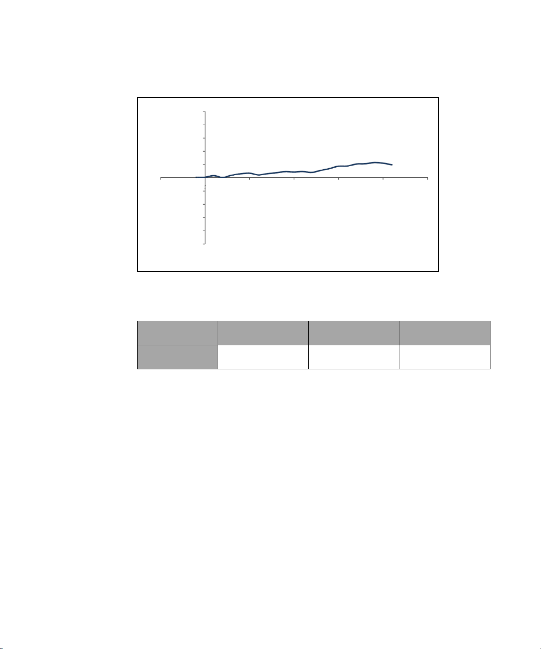
Figure 2-12 Typical N8481/2/5/7/8A and N8486AR/AQ power linearity at 25 °C, after
zero and calibration with associated measurement uncertainty
N8481/2/5/7/8A
and N8486AR/AQ
Measurement
Uncertainty (%)
32 N8480 Series Power Sensors Operating and Service Guide
–1 dBm to +10 dBm +10 dBm to +15 dBm +15 dBm to +20 dBm
±0.35 ±0.35 ±0.35
Page 49

Specifications and Characteristics 2
Input Power (dBm)
% Error
0.2
0.4
0.6
1.0
0.8
–1.0
–0.8
–0.6
–0.2
–0.4
5
0
10
20
25
15
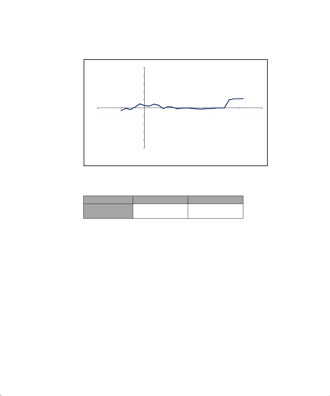
Figure 2-13 Typical N8481/2B power linearity at 25 °C, after zero and calibration with
associated measurement uncertainty
N8481/2B +29 dBm to +40 dBm +40 dBm to +44 dBm
Measurement
Uncertainty (%)
±0.35 ±1.21
N8480 Series Power Sensors Operating and Service Guide 33
Page 50
2 Specifications and Characteristics
Input Power (dBm)
% Error
0
0.2
0.4
0.6
1.0
0.8
–1.0
–0.8
–0.6
–0.2
–0.4
–5
5
20
10
25
15
–10
Figure 2-14 Typical N8481/2H power linearity at 25 °C, after zero and calibration with
associated measurement uncertainty
N8481/2H +17 dBm to +30 dBm +30 dBm to +35 dBm
Measurement
Uncertainty (%)
±0.60 ±2.39
34 N8480 Series Power Sensors Operating and Service Guide
Page 51

Specifications and Characteristics 2
NOTE
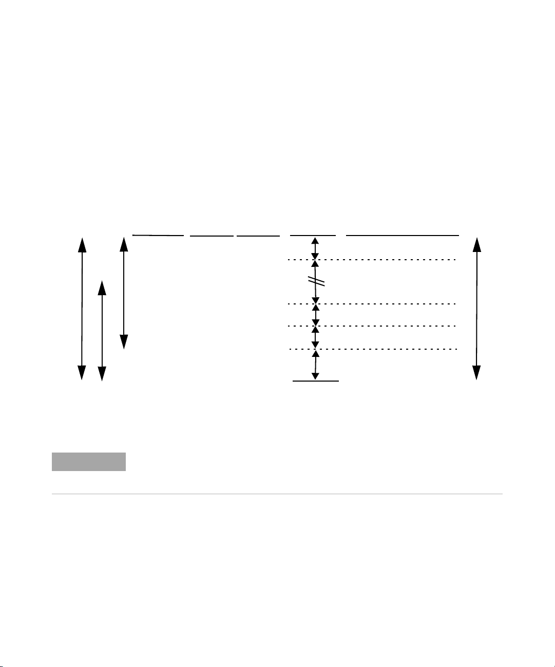
Switching Point
Switching point is applicable for standard N8480 Series power sensors only.
The N8480 Series power sensors have two power measurement ranges; a
lower range and upper range. The power meter automatically selects the
proper power range. To avoid unnecessary switching when the power level
is near switching point, a Switching Point Hysteresis has been added.
Tab l e 2 - 5 Switching point hysteresis
Switching point hysteresis 0.5 dB
N8481/2/5/7/8A and N8486AQ/AR power sensors
This hysteresis causes the lower range to remain selected until
approximately –0.5 dBm as the power level is increased, above this power
the upper range is selected.
The upper range remains selected until approximately –1.5 dBm as the
signal level decreases, below this power the lower range is selected.
N8481/2B power sensors
This hysteresis causes the lower range to remain selected until
approximately 29.5 dBm as the power level is increased, above this power
the upper range is selected.
The upper range remains selected until approximately 28.5 dBm as the
signal level decreases, below this power the lower range is selected.
N8481/2H power sensors
This hysteresis causes the lower range to remain selected until
approximately 17.5 dBm as the power level is increased, above this power
the upper range is selected.
The upper range remains selected until approximately 16.5 dBm as the
signal level decreases, below this power the lower range is selected.
N8480 Series Power Sensors Operating and Service Guide 35
Page 52

2 Specifications and Characteristics
Zero Set, Zero Drift and Measurement Noise
Tab l e 2 - 6 Zero set, zero drift and measurement noise
Sensor
Model
N8481A
N8482A
N8485A
N8486AR
N8486AQ
N8487A
N8488A
N8481B
N8482B
N8481H
N8482H
Sensor Option Range
Upper 20% to 70% ±63 nW < ±7 nW < 114 nW
Standard
Lower 20% to 70% ±25 nW < ±3 nW < 80 nW
Option CFT N/A
Upper 20% to 70% ±63 nW < ±7 nW < 114 nW
Standard
Lower 20% to 70% ±25 nW < ±3 nW < 80 nW
Option CFT N/A
Upper 20% to 70% ±63 µW < ±7 µW < 114 µW
Standard
Lower 20% to 70% ±25 µW < ±3 µW < 80 µW
Option CFT N/A
Upper 20% to 70% ±6.3 µW < ±0.7 µW < 11.4 µW
Standard
Lower 20% to 70% ±2.5 µW < ±0.3 µW < 8 µW
Option CFT N/A
Conditions
1
(RH)
5
5
5
5
20% to 70% ±63 nW < ±7 nW < 114 nW
5
N/A
20% to 70% ±63 µW < ±7 µW < 114 µW
20% to 70% ±6.3 µW < ±0.7 µW < 11.4 µW
Zero Set
N/A
4
Zero Drift
5
N/A
5
2, 4
Measurement
Noise
N/A
3, 4
5
1. RH is the abbreviation for relative humidity.
2. Within one hour after zero set, at a constant temperature, after a 24 hour warm-up of the power meter with sensor connected.
3. The number of averages at 16 for normal mode and 32 for x2 mode, at a constant temperature,
measured over one minute interval and two standard deviations.
4. The zero set, zero drift, and measurement noise specifications are tested at 50 MHz.
5. N/A is the abbreviation for “not applicable”.
36 N8480 Series Power Sensors Operating and Service Guide
Page 53

Specifications and Characteristics 2
x2 Mode
Maximum sensor power
Sensor
Dynamic
Range
180 ms
Minimum sensor power
400 ms
3.6 s
150 ms
Ty p i c a l
Settling
Times
10 dB
10 dB
10 dB
20 dB
6.6 s
5 dB
Normal Mode
Maximum sensor power
Sensor
Dynamic
Range
200 ms
Minimum sensor power
1 s
6.6 s
150 ms
Ty p i c a l
Settling
Times
10 dB
10 dB
10 dB
20 dB
13.5 s
5 dB
Settling Time
In normal and x2 mode, manual filter, 10 dB decreasing power step (not
across the switching point), the settling time is shown in Table 2- 7.
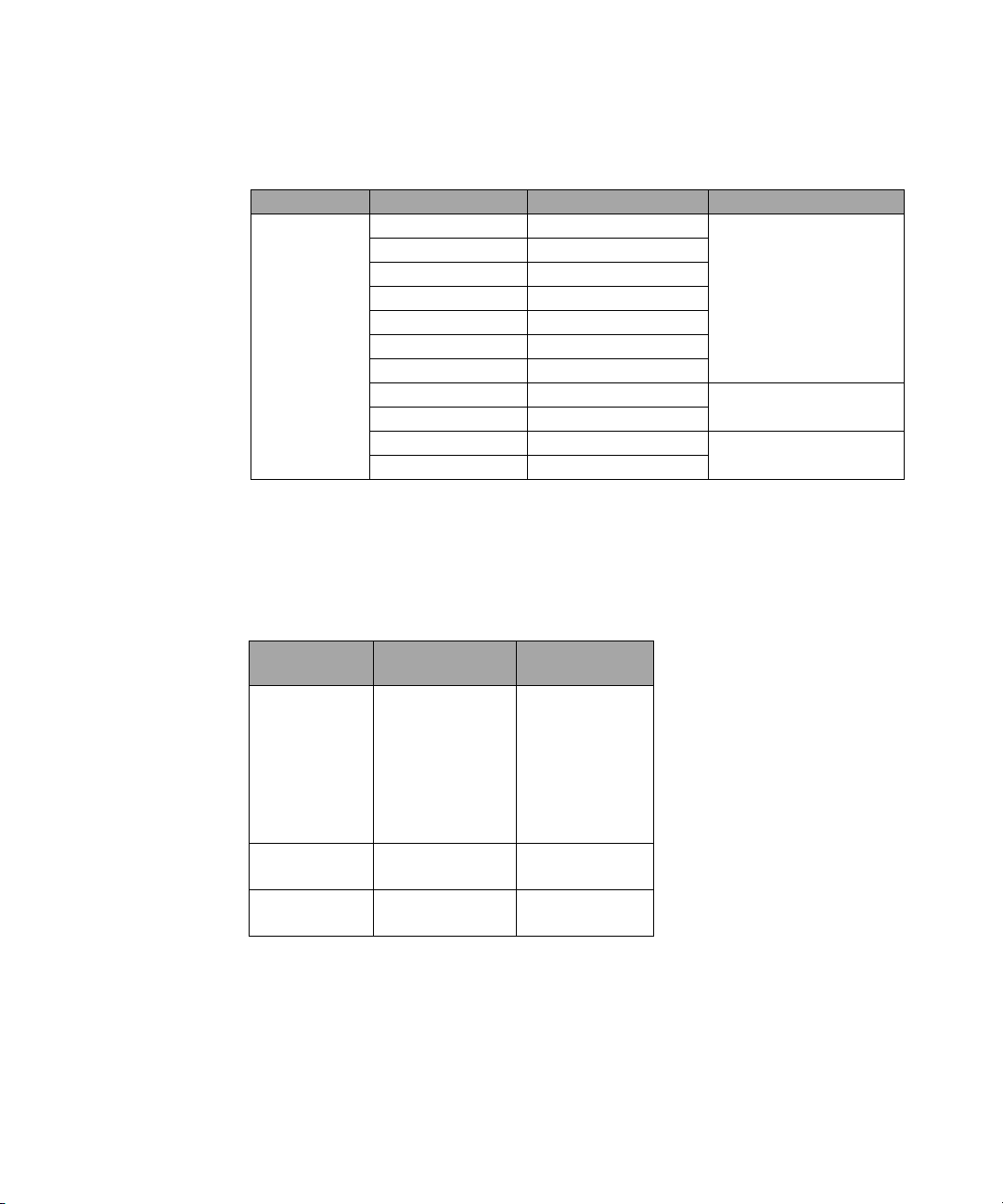
Tab l e 2 - 7 Settling time in normal and x2 mode
Number of
Averages
Settling Time (s)
(Normal mode)
Response Time
(s) (x2 mode)
1 2 4 8 16 32 64 128 256 512 1024
0.15 0.2 0.3 0.5 1.1 1.9 3.4 6.6 13 27 57
0.15 0.18 0.22 0.35 0.55 1.1 1.9 3.5 6.9 14.5 33
Figure 2-15 Autofilter, default resolution, 10 dB decreasing power step (not across the
switching point)
N8480 Series Power Sensors Operating and Service Guide 37
Page 54

2 Specifications and Characteristics
1 +
r
1 –
r
SWR =
NOTE
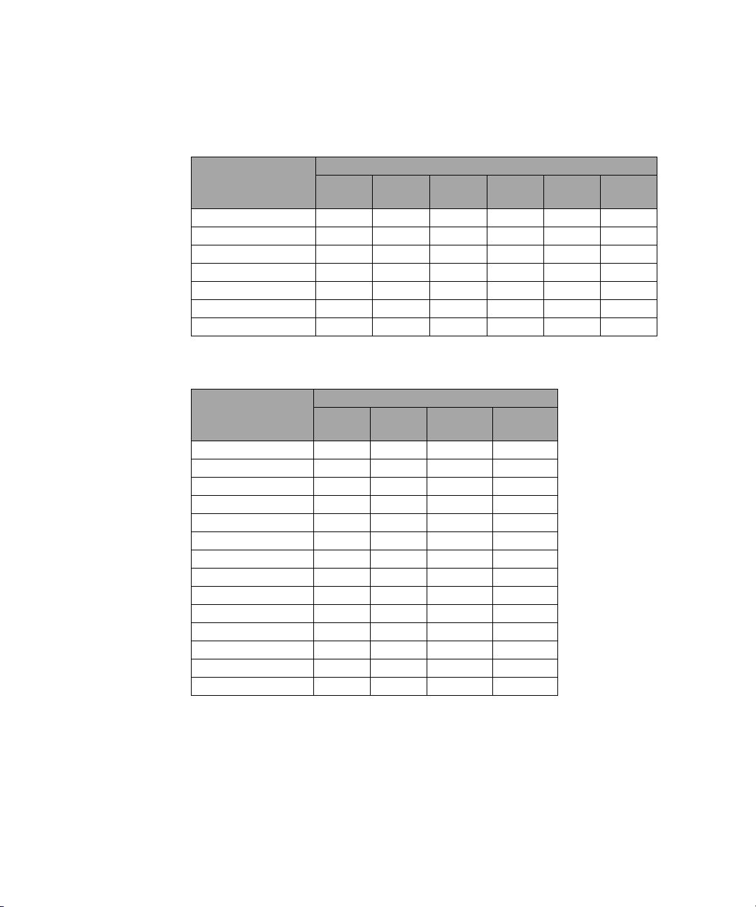
Calibration Factor and Reflection Coefficient
Calibration Factor (CF) and Reflection Coefficient (Rho) data are provided
on a data sheet included with the power sensor. This data is unique to
each power sensor. If you have more than one power sensor, match the
serial number on the data sheet with the serial number on the power
sensor you are using. The CF corrects for the frequency response of the
power sensor. The Agilent EPM Series, EPM- P Series, or P- Series power
meters automatically read the CF data stored in the power sensor’s
EEPROM and use it to make the corrections.
Reflection Coefficient (Rho, or
following formula:
Typical measurement uncertainties of the Calibration Factor (CF) are
listed in the following tables. There is only one set of CF data used for
both high and low range of each power sensors. Therefore, there is only
one set of measurement uncertainty data available. The typical
measurement uncertainty data listed in this guide is meant to help users
on the measurement uncertainty estimation. These values are only a
guideline and are not to be used in any accurate uncertainty calculations.
For accurate measurement uncertainty values, please refer to the
measurement report
Do not assume the typical measurement uncertainty listed in this guide as the maximum
calibration factor measurement uncertainty.
1
of the specific power sensor.
r
) relates to the SWR according to the
38 N8480 Series Power Sensors Operating and Service Guide
1
Only applicable with the purchase of Option 1A7 or Option A6J.
Page 55
Specifications and Characteristics 2
Calibration Factor Uncertainty
Tab l e 2 - 8 Calibration factor uncertainty at 25 ºC ± 3 ºC
25 ºC ± 3 ºC
Frequency
100 kHz to 10 MHz - - - 0.91 1.48 0.89
10 MHz to 30 MHz 0.82 1.42 0.77 0.78 1.43 0.79
30 MHz to 500 MHz 0.77 1.48 0.89 0.77 1.49 0.89
500 MHz to 1.2 GHz 0.78 1.48 0.89 0.78 1.49 0.89
1.2 GHz to 6 GHz 0.91 1.58 1.06 0.89 1.56 1.02
6 GHz to 14 GHz 1.26 1.77 1.46 - - -
14 GHz to 18 GHz 1.59 1.92 1.73 - - -
Tab l e 2 - 8 Calibration factor uncertainty at 25 ºC ± 3 ºC (continued)
Frequency
N8481A N8481B N8481H N8482A N8482B N8482H
25 ºC ± 3 ºC
N8485A N8487A N8486AR N8486AQ
100 kHz to 10 MHz - - - -
10 MHz to 30 MHz 0.82 - - 30 MHz to 500 MHz 1.24 1.33 - 500 MHz to 1.2 GHz 1.26 1.35 - -
1.2 GHz to 6 GHz 1.35 1.41 - 6 GHz to 14 GHz 1.66 1.61 - -
14 GHz to 18 GHz 1.83 1.73 - -
18 GHz to 26.5 GHz 2.67 2.26 - -
26.5 GHz to 33 GHz 3.32 2.58 2.68 33 GHz to 34 GHz - 2.80 3.19 3.14
34 GHz to 35 GHz - 2.80 3.19 3.40
35 GHz to 40 GHz - 2.80 3.19 3.14
40 GHz to 45 GHz - 3.66 - 3.19
45 GHz to 50 GHz - 4.23 - 3.26
N8480 Series Power Sensors Operating and Service Guide 39
Page 56
2 Specifications and Characteristics
Tab l e 2 - 8 Calibration factor uncertainty at
25 ºC ± 3 ºC
Frequency
100 kHz to 50 MHz 1.70
50 MHz to 100 MHz 1.60
100 MHz to 2 GHz 1.58
2 GHz to 12.4 GHz 1.75
12.4 GHz to 18 GHz 1.92
18 GHz to 26.5 GHz 2.43
16.5 GHz to 50 GHz 4.56
50 GHz to 67 GHz 5.30
67 GHz to 70 GHz 5.81
N8488A
25 ºC ± 3 ºC (continued)
Tab l e 2 - 9 Calibration factor uncertainty at 25 ºC ± 10 ºC
25 ºC ± 10 ºC
Frequency
100 kHz to 10 MHz - - - 1.28 2.40 0.99
10 MHz to 30 MHz1.471.981.391.031.840.86
30 MHz to 500 MHz1.031.911.101.031.830.98
500 MHz to 1.2 GHz0.971.911.151.081.941.00
1.2 GHz to 6 GHz 1.231.971.421.812.681.19
6 GHz to 14 GHz 1.85 2.69 3.87 - - -
14 GHz to 18 GHz 2.17 3.20 7.01 - - -
N8481A N8481B N8481H N8482A N8482B N8482H
40 N8480 Series Power Sensors Operating and Service Guide
Page 57

Specifications and Characteristics 2
Tab l e 2 - 9 Calibration factor uncertainty at
Frequency
100 kHz to 10 MHz - - - -
10 MHz to 30 MHz 0.94 - - 30 MHz to 500 MHz 1.43 1.84 - 500 MHz to 1.2 GHz 1.52 2.10 - -
1.2 GHz to 6 GHz 1.68 2.36 - 6 GHz to 14 GHz 2.26 2.87 - -
14 GHz to 18 GHz 2.47 3.14 - -
18 GHz to 26.5 GHz 3.75 3.77 - -
26.5 GHz to 33 GHz 4.79 4.17 3.48 33 GHz to 34 GHz - 4.55 4.07 5.02
34 GHz to 35 GHz - 4.55 4.07 4.99
35 GHz to 40 GHz - 4.55 4.07 5.02
40 GHz to 45 GHz - 5.40 - 5.17
45 GHz to 50 GHz - 6.02 - 5.20
N8485A N8487A N8486AR N8486AQ
25 ºC ± 10 ºC (continued)
25 ºC ± 10 ºC
Tab l e 2 - 9 Calibration factor uncertainty at 25 ºC ± 10 ºC (continued)
25 ºC ± 3 ºC
Frequency
N8488A
100 kHz to 50 MHz 2.83
50 MHz to 100 MHz 1.98
100 MHz to 2 GHz 1.84
2 GHz to 12.4 GHz 2.45
12.4 GHz to 18 GHz 2.89
18 GHz to 26.5 GHz 3.52
16.5 GHz to 50 GHz 4.99
50 GHz to 67 GHz 6.46
67 GHz to 70 GHz 7.29
N8480 Series Power Sensors Operating and Service Guide 41
Page 58
2 Specifications and Characteristics
Tab l e 2 - 10 Calibration factor uncertainty at
Frequency
100 kHz to 10 MHz - - - 1.59 2.67 1.41
10 MHz to 30 MHz 4.46 3.64 2.83 0.91 1.73 0.86
30 MHz to 500 MHz 1.57 2.22 1.44 1.16 1.77 1.03
500 MHz to 1.2 GHz 1.65 2.49 1.60 1.54 2.12 1.07
1.2 GHz to 6 GHz 2.04 2.85 1.96 1.99 3.91 1.40
6 GHz to 14 GHz 2.62 3.81 4.81 - - -
14 GHz to 18 GHz 3.27 4.30 9.74 - - -
N8481A N8481B N8481H N8482A N8482B N8482H
0 ºC to 55 ºC
0 ºC to 55 ºC
Tab l e 2 - 10 Calibration factor uncertainty at 0 ºC to 55 ºC (continued)
0 ºC to 55 ºC
Frequency
100 kHz to 10 MHz - - - -
10 MHz to 30 MHz 1.25 - - 30 MHz to 500 MHz 1.98 2.14 - 500 MHz to 1.2 GHz 2.07 2.45 - -
1.2 GHz to 6 GHz 2.40 2.65 - 6 GHz to 14 GHz 2.99 3.17 - -
14 GHz to 18 GHz 3.35 3.41 - -
18 GHz to 26.5 GHz 4.70 4.04 - -
26.5 GHz to 33 GHz 6.41 4.43 3.76 33 GHz to 34 GHz - 4.84 4.25 6.04
34 GHz to 35 GHz - 4.84 4.25 6.04
35 GHz to 40 GHz - 4.84 4.25 6.04
40 GHz to 45 GHz - 5.70 - 5.86
45 GHz to 50 GHz - 6.19 - 6.59
N8485A N8487A N8486AR N8486AQ
42 N8480 Series Power Sensors Operating and Service Guide
Page 59
Specifications and Characteristics 2
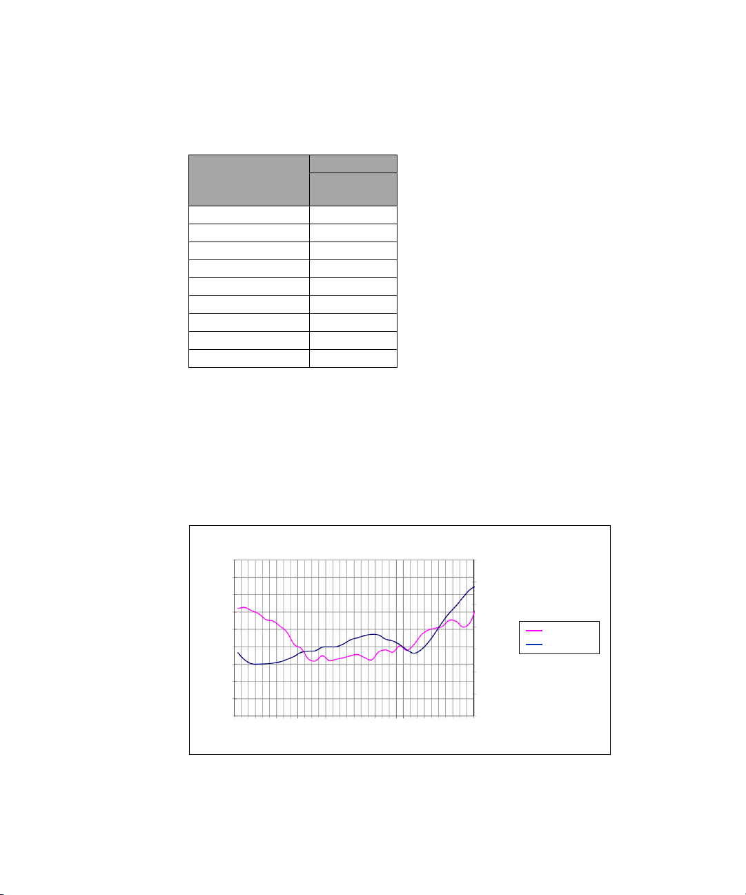
92
0.9
0.95
1
1.05
1.1
1.15
Ty p ic al CF
Ty p ic al SW R
Cal Factor
SWR
Typical CF and SWR vs. Frequency
91
0.05
1
12
8
4
15
19
93
94
95
96
97
98
99
100
1
1.2
1.25
Frequency (GHz)
23
27
Tab l e 2 - 10 Calibration factor uncertainty at
0 ºC to 55 ºC (continued)
25 ºC ± 3 ºC
Frequency
N8488A
100 kHz to 50 MHz 3.69
50 MHz to 100 MHz 2.63
100 MHz to 2 GHz 2.40
2 GHz to 12.4 GHz 2.61
12.4 GHz to 18 GHz 3.15
18 GHz to 26.5 GHz 4.50
16.5 GHz to 50 GHz 5.67
50 GHz to 67 GHz 7.18
67 GHz to 70 GHz 8.69
Supplemental Characteristics
Supplemental characteristics are intended to provide additional
information, useful in applying the power sensor by giving a typical but
not warranted performance parameters.
N8480 Series Power Sensors Operating and Service Guide 43
Figure 2-16 Typical cal factor and SWR vs. frequency
Page 60

2 Specifications and Characteristics
Width (W)
Height (H)
Length (L)
Physical Characteristics
Tab l e 2 - 11 Physical dimensions
Sensor Model Dimensions Weight
N8481A
N8482A
N8485A
38 mm W x 30 mm H x 121 mm L
N8487A 38 mm W x 30 mm H x 121 mm L
N8488A
N8486AR 38 mm W x 62 mm H x 152 mm L
N8486AQ 38 mm W x 62 mm H x 152 mm L
N8481B
N8482B
N8481H
N8482H
38 mm W x 30 mm H x 130 mm L
(1.5 in X 1.2 in X 5.1 in)
(1.5 in X 1.2 in X 4.75 in)
(1.5 in X 1.2 in X 4.75 in)
38 mm W x 30 mm H x 115 mm L
(1.5 in X 1.2 in X 4.5 in)
(1.5 in X 2.4 in X 6.0 in)
(1.5 in X 2.4 in X 6.0 in)
83 mm W x 114 mm H x 283 mm L
(3.2 in X 4.5 in X 11.1 in)
38 mm W x 30 mm H x 174 mm L
(1.5 in X 1.2 in X 6.8 in)
Net: 0.181 kg (0.40 lb)
Shipping: 0.90 kg (1.98 lb)
Net: 0.183 kg (0.40 lb)
Shipping: 0.90 kg (1.98 lb)
Net: 0.154 kg (0.34 lb)
Shipping: 0.874 kg (1.92 lb)
Net: 0.162 kg (0.36 lb)
Shipping: 0.881 kg (1.94 lb)
Net: 0.202 kg (0.45 lb)
Shipping: 0.922 kg (2.03 lb)
Net: 0.204 kg (0.45 lb)
Shipping: 0.924 kg (2.03 lb)
Net: 0.684 kg (1.51 lb)
Shipping: 1.404 kg (3.09 lb)
Net: 0.234 kg (0.52 lb)
Shipping: 0.954 kg (2.10 lb)
44 N8480 Series Power Sensors Operating and Service Guide
Page 61

N8480 Series Power Sensors
Operating and Service Guide
3 Service
Cleaning 46
Connector Care 46
Principle of Operations 47
Performance Test 48
Replaceable Parts 51
Troubleshooting 57
Repair 57
Diassembly/Reassembly Procedures 58
Diassembly Procedure 58
Reassembly Procedure 58
This chapter contains information about principle of operations, troubleshooting, and repair
of the Agilent N8480 Series power sensors.
Agilent Technologies
45
Page 62

3Service
CAUTION
Cleaning
Use a clean, damp cloth to clean the body of the N8480 Series power
sensors.
Connector Care
A solution of pure isopropyl or ethyl alchohol can be used to clean
connectors but make sure to keep in mind on its flammable nature.
• The RF connector bead deteriorates when contacted with any chlorinated or
aromatic hydrocarbon such as acetone, thrichlorethane, carbon tetrachloride,
and benzene.
• Do not attempt to clean connectors with anything metallic such as pins or
paper clips.
46 N8480 Series Power Sensors Operating and Service Guide
Clean the connector only at a static free workstation. Electrostatic
discharge to the center pin of the connector will render the power
sensor inoperative.
Clean the connector face by first using a blast of compressed air. If the
compressed air fails to remove contaminants, use a cotton swab dipped in
isopropyl or ethyl alcohol. If the swab is too big, use a round wooden
toothpick wrapped in a lint free cloth dipped in isopropyl or ethyl alcohol.
Page 63

Principle of Operations
The A1 module assembly (refer to Figure 3- 1) on the Agilent N8480 Series
power sensors provides a 50 W load to the RF signal applied to the power
sensor. A thermocouple assembly in the bulkhead converts the applied RF
to produce DC voltages which vary with the RF power across the
50 W load.
The low- level DC voltages from the bulkhead assembly are amplified
before they are transferred on standard cables to the power meter. The
amplification is provided by an input amplifier assembly which consists of
a chopper (sampling gate) and an input amplifier. The chopper circuit
converts the DC voltages to AC voltages. The chopper is controlled by a
440 Hz square wave generated by the power meter. The amplitude of the
sampling gate output is a 440 Hz square wave which varies with the RF
power input. The 440 Hz AC output is applied to an amplifier which
provides the input to the power meter.
The Agilent EPM Series, EPM- P Series, or P- Series power meters
automatically detects the power sensor when an Agilent N8480 Series
power sensor is connected and downloads the correction data from the
sensor’s EEPROM. The auto- averaging settings are also configured
automatically for use with Agilent N8480 Series power sensors. This
configures the power meter to operate over the range with that particular
sensor’s unique correction data applied.
Service 3
N8480 Series Power Sensors Operating and Service Guide 47
Page 64

3Service
NOTE
Performance Test
Standing Wave Ratio (SWR) and Reflection Coefficient (Rho) Performance Test
This section does not establish preset SWR test procedures since there are
several test methods and different equipment available for testing the SWR
or reflection coefficient. Therefore, the actual accuracy of the test
equipment must be accounted for when measuring against instrument
specifications to determine a pass or fail condition. The test system used
must not exceed the system Rho uncertainties shown in Table 3- 1 when
testing the N8480 Series power sensors.
To check the calibration factor, the power sensor should be compared with
another recently calibrated power sensor. The source should be leveled
with a reference coupler that has low SWR and high directivity to monitor
or level the incident power.
For calibration factor and error analysis, refer to Agilent Application Note
AN1449- 1 to AN1449- 4 (Part 1 to Part 4), “Fundamentals of RF and
Microwave Power Measurement”.
Waveguide power sensors only (N8486AR and N8486AQ)
• While the flange of the N8486AR is similar to the one described in MIL F-3922/54C-003,
the N8486AQ is modified to mate with the greater precision of MIL-3922/67B-006
flanges. The true position of the holes relative to each other are held to a diameter
tolerance of 0.0254 mm (0.001 in). The holes are held to 1.664 mm (0.0655 in) minimum
diameter while the pins are held to 1.61 mm (0.0634 in) maximum diameter.
48 N8480 Series Power Sensors Operating and Service Guide
Page 65

Service 3
Tab l e 3 - 1 Reflection coefficient for N8480 Series power sensors (25 ºC ± 10 ºC)
Sensor Model Frequency
10 MHz to 30 MHz ±0.007 0.157
30 MHz to 50 MHz ±0.005 0.067
N8481A
N8482A
N8485A
N8487A
50 MHz to 2 GHz ±0.005 0.040
2 GHz to 12.4 GHz ±0.012 0.073
12.4 GHz to 18 GHz ±0.013 0.105
100 kHz to 300 kHz ±0.007 0.212
300 kHz to 1 MHz ±0.005 0.077
1 MHz to 2 GHz ±0.008 0.030
2 GHz to 6 GHz ±0.009 0.035
10 MHz to 50 MHz ±0.011 0.143
50 MHz to 100 MHz ±0.006 0.038
100 MHz to 2 GHz ±0.005 0.025
2 GHz to 12.4 GHz ±0.009 0.064
12.4 GHz to 18 GHz ±0.011 0.085
18 GHz to 26.5 GHz ±0.014 0.114
26.5 GHz to 33 GHz ±0.020 0.139
50 MHz to 100 MHz ±0.013 0.038
100 MHz to 2 GHz ±0.011 0.026
2 GHz to 12.4 GHz ±0.011 0.049
12.4 GHz to 18 GHz ±0.014 0.072
18 GHz to 26.5 GHz ±0.022 0.099
26.5 GHz to 40 GHz ±0.039 0.130
40 GHz to 50 GHz ±0.055 0.144
System Rho
Uncertainty
Actual
Measurement
Maximum
Rho
N8480 Series Power Sensors Operating and Service Guide 49
Page 66
3Service
Tab l e 3 - 1 Reflection coefficient for N8480 Series power sensors (25 ºC ± 10 ºC)
Sensor Model Frequency
10 MHz to 100 MHz ±0.005 0.016
100 MHz to 2.4 GHz ±0.004 0.018
2.4 GHz to 12.4 GHz ±0.004 0.043
N8488A
N8486AR 26.5 GHz to 40 GHz ±0.021 0.168
N8486AQ 33 GHz to 50 GHz ±0.054 0.200
N8481B
N8482B
N8481H
12.4 GHz to 18 GHz ±0.005 0.056
18 GHz to 26.5 GHz ±0.007 0.099
26.5 GHz to 40 GHz ±0.011 0.133
40 GHz to 67 GHz ±0.022 0.190
67 GHz to 70 GHz ±0.026 0.200
10 MHz to 2 GHz ±0.007 0.042
2 GHz to 12.4 GHz ±0.018 0.066
12.4 GHz to 18 GHz ±0.023 0.102
100 kHz to 2 GHz ±0.011 0.041
2 GHz to 6 GHz ±0.013 0.074
10 MHz to 8 GHz ±0.015 0.075
8 GHz to 12.4 GHz ±0.021 0.099
12.4 GHz to 18 GHz ±0.046 0.140
System Rho
Uncertainty
Actual
Measurement
Maximum
Rho
N8482H 100 kHz to 6 GHz ±0.012 0.063
50 N8480 Series Power Sensors Operating and Service Guide
Page 67

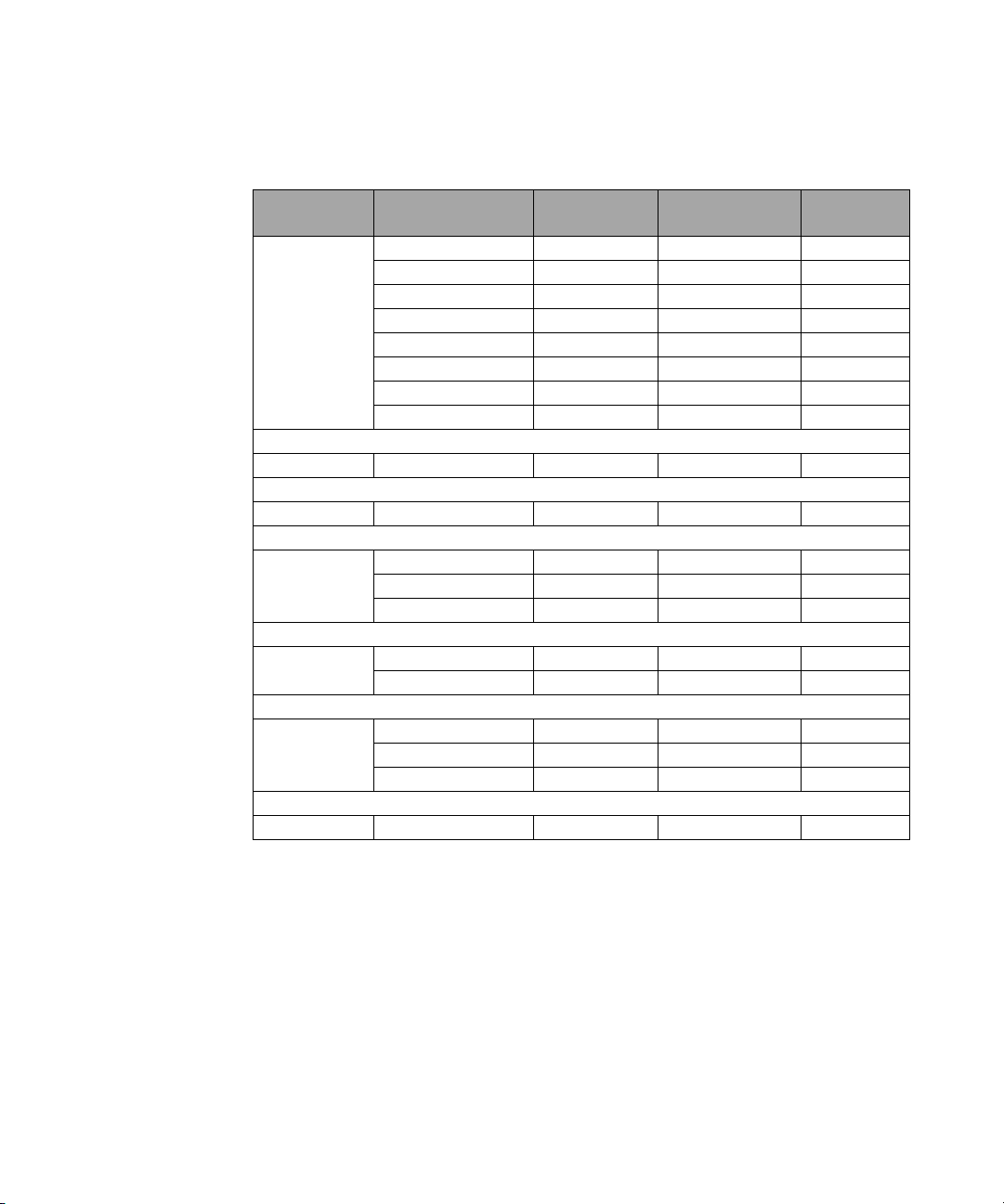
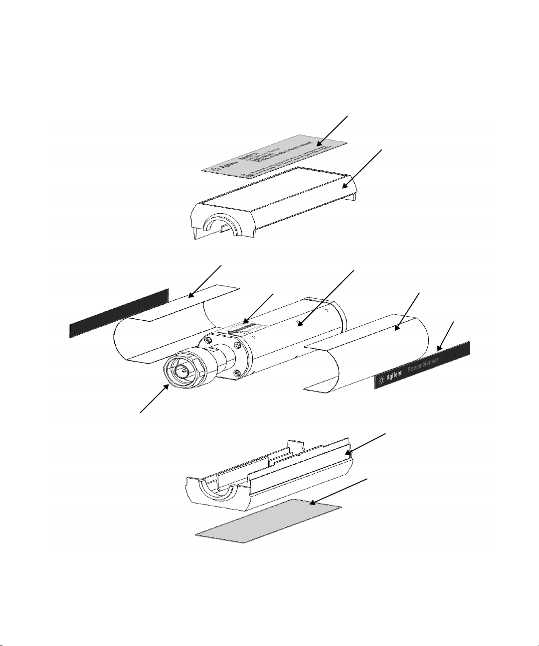
Replaceable Parts
NOTE
Figure 3- 1 illustrates the parts breakdown of the N8480 Series power
sensors that identifies all the replaceable parts. If you want to order a
part, quote the Agilent part number, specify the quantity required, and
address the order to the nearest Agilent office.
If you are located within United States, you are adviced to order directly from the Agilent
Parts Center in Roseville, California.
Ask your nearest Agilent office for ordering information and forms for the “Direct Mail
Order System”. Information such as toll free telephone number will be provided.
Service 3
N8480 Series Power Sensors Operating and Service Guide 51
Page 68
3Service
MP5
MP1
MP 4
MP2
MP6
MP4
MP1
MP3
A1
MP2
Figure 3-1 Illustrated Parts Breakdown
52 N8480 Series Power Sensors Operating and Service Guide
Page 69

Tab l e 3 - 2 Replaceable parts list for standard N8480 Series power sensors
Service 3
Reference
Designaton
A1
N8481A
N8482A N8482A-100 N8482-60002 1
N8485A N8485A-100 N8485-60002 1
N8487A N8487A-100 N8487-60005 1
N8488A N8488A-100 N8488-60006 1
N8481B N8181B-100 N8481-60012 1
N8482B N8482B-100 N8482-60008 1
N8481H N8481H-100 N8481-60014 1
N8482H N8482H-100 N8482-60010 1
N8486AR N8486AR-100 N8486-60010 1
N8486AQ N8486AQ-100 N8486-60008 1
Option Part Number Quantity Description
N8481A-100 N8481-60007 1
N8481A-200 N8481-60008 1
N8481A (Type-N)
replacement module
N8481A (APC-7)
replacement module
N8482A (Type-N)
replacement module
N8485A (3.5 mm)
replacement module
N8487A (2.4 mm)
replacement module
N8488A (1.85 mm)
replacement module
N8481B (Type-N)
replacement module
N8482B (Type-N)
replacement module
N8481H (Type-N)
replacement module
N8482H (Type-N)
replacement module
N8486AR (Waveguide flange
UG-599/U)
replacement module
N8486AQ (Waveguide flange
UG-383/U)
replacement module
Chassis Parts
MP1 - E9321-40001 2 Plastic shell
MP2 - E9321-00001 2 Shield
MP3 - N8481-84301 1 Label-ID top (N8481A)
MP3 - N8482-84301 1 Label-ID top (N8482A)
MP3 - N8485-84301 1 Label-ID top (N8485A)
N8480 Series Power Sensors Operating and Service Guide 53
Page 70

3Service
Tab l e 3 - 2 Replaceable parts list for standard N8480 Series power sensors
Reference
Designaton
MP3 - N8485-84303 1
MP3 - N8487-84301 1 Label-ID top (N8487A)
MP3 - N8488-84301 1 Label-ID top (N8488A)
MP3 - N8486-84301 1 Label-ID top (N8486AR)
MP3 - N8486-84302 1 Label-ID top (N8486AQ)
MP3 - N8481-84302 1 Label-ID top (N8481B)
MP3 - N8482-84302 1 Label-ID top (N8482B)
MP3 - N8481-84303 1 Label-ID top (N8481H)
MP3 - N8482-84303 1 Label-ID top (N8482H)
MP4 - N8481-84304 2 Label-Side
MP5 - N8481-84305 1 Label-Cert. bottom
MP6 - 00346-80011 1 Label-Information
Option Part Number Quantity Description
Label-ID top
(N8485A Option 033)
54 N8480 Series Power Sensors Operating and Service Guide
Page 71

Service 3
Tab l e 3 - 3 Replaceable parts list for N8480 Series power sensors with Option CFT
Reference
Designaton
A1
N8481A
N8482A N8482A-100 N8482-60007 1
N8485A N8485A-100 N8485-60003 1
N8487A N8487A-100 N8487-60006 1
N8481B N8181B-100 N8481-60013 1
N8482B N8482B-100 N8482-60009 1
N8481H N8481H-100 N8481-60015 1
N8482H N8482H-100 N8482-60011 1
N8486AR N8486AR-100 N8486-60011 1
N8486AQ N8486AQ-100 N8486-60009 1
Option Part Number Quantity Description
N8481A-100 N8481-60009 1
N8481A-200 N8481-60010 1
N8481A (Type-N) replacement
module, CFT Option
N8481A (APC-7) replacement
module, CFT Option
N8482A (Type-N) replacement
module, CFT Option
N8485A (3.5 mm), replacement
module, CFT Option
N8487A (2.4 mm) replacement
module, CFT Option
N8481B (Type-N) replacement
module, CFT Option
N8482B (Type-N) replacement
module, CFT Option
N8481H (Type-N) replacement
module, CFT Option
N8482H (Type-N) replacement
module, CFT Option
N8486AR (Waveguide flange
UG-599/U) replacement
module, CFT Option
N8486AQ (Waveguide flange
UG-383/U) replacement
module, CFT Option
Chassis Parts
MP1 - E9321-40001 2 Plastic shell
MP2 - E9321-00001 2 Shield
MP3 - N8481-84307 1 Label-ID top (N8481A)
MP3 - N8482-84306 1 Label-ID top (N8482A)
MP3 - N8485-84302 1 Label-ID top (N8485A)
MP3 - N8485-84304 1
MP3 - N8487-84302 1 Label-ID top (N8487A)
MP3 - N8486-84303 1 Label-ID top (N8486AR)
Label-ID top
(N8485A Option 033)
N8480 Series Power Sensors Operating and Service Guide 55
Page 72

3Service
Tab l e 3 - 3 Replaceable parts list for N8480 Series power sensors with Option CFT
Reference
Designaton
MP3 - N8486-84304 1 Label-ID top (N8486AQ)
MP3 - N8481-84310 1 Label-ID top (N8481B)
MP3 - N8482-84309 1 Label-ID top (N8482B)
MP3 - N8481-84311 1 Label-ID top (N8481H)
MP3 - N8482-84310 1 Label-ID top (N8482H)
MP4 - N8481-84304 2 Label-Side
MP5 - N8481-84306 1
MP6 - 00346-80011 1 Label-Information
Option Part Number Quantity Description
Label ID Certification Bottom
- CFT Option
56 N8480 Series Power Sensors Operating and Service Guide
Page 73

Troubleshooting
Troubleshooting information is intended to first isolate the power sensor,
cable, or power meter as the defective component. When the power sensor
is isolated, an appropriate sensor module must be used for repair. See
Table 3- 2 and Table 3- 3.
If error message 241 or 310 is displayed on the power meter, suspect a
power sensor failure. Error 241 will occur if the power sensor is missing.
A supported cable must be used to connect the N8480 Series power
sensors to a power meter.
If no error message is displayed, but a problem occurs when making a
measurement, try replacing the cable from the power meter to the power
sensor. If the problem still exists, try using a different power sensor to
determine if the problem is in the power meter or in the power sensor.
Electrostatic discharge will render the power sensor inoperative. Do not,
under any circumstances, open the power sensor unless you and the
power sensor are in a static free environment.
Service 3
Repair
There is no serviceable parts inside the N8480 Series power sensors. If the
power sensor is defective, send it back to the nearest Agilent Service
Center for repair. The entire “module” of the defective power sensor will
be replaced with an appropriate replacement module listed in Table 3- 2
and Table 3- 3.
N8480 Series Power Sensors Operating and Service Guide 57
Page 74
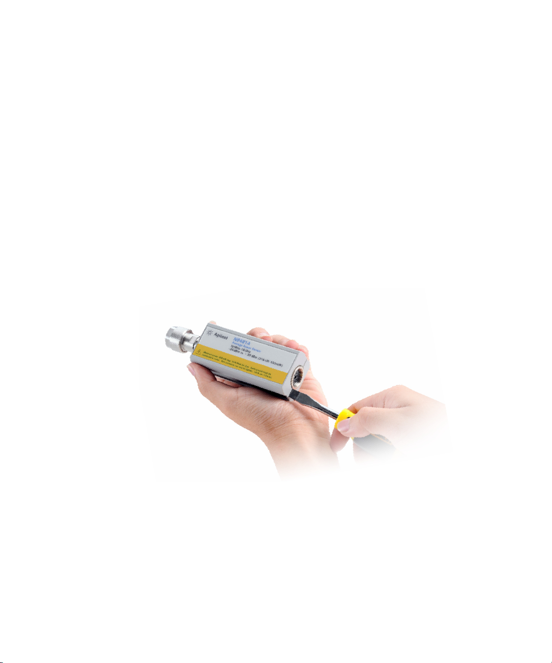
3Service
Diassembly/Reassembly Procedures
Diassembly Procedure
Disassemble the power sensor by performing the following steps:
• Diassemble the power sensor only in a static free workstation.
Electrostatic discharge renders the power sensor inoperative.
• At the rear of the power sensor, insert the blade of a screwdriver
between the plastic shells (See Figure 3- 2). To prevent damage to the
plastic shells use a screwdriver blade as wide as the slot between the
two shells.
• Pry alternately at both sides of the connector until the plastic shells are
apart. Remove the shells and the magnetic shields.
Figure 3-2 Removing power sensor shell
Reassembly Procedure
Replace the magnetic shields and the plastic shells. Snap the plastic shells
together.
58 N8480 Series Power Sensors Operating and Service Guide
Page 75

www.agilent.com
Contact us
T
o obtain service, warranty or technical support
assistance, contact us at the
following phone numbers:
United States:
(tel) 800 829 4444 (fax) 800 829 4433
Canada:
(tel) 877 894 4414 (fax) 800 746 4866
China:
(tel) 800 810 0189 (fax) 800 820 2816
Europe:
(tel) 31 20 547 2111
Japan:
(tel) (81) 426 56 7832 (fax) (81) 426 56 7840
Korea:
(tel) (080) 769 0800 (fax) (080) 769 0900
Latin America:
(tel) (305) 269 7500
Ta i w a n :
(tel) 0800 047 866 (fax) 0800 286 331
Other Asia Pacific Countries:
(tel) (65) 6375 8100 (fax) (65) 6755 0042
Or visit Agilent worlwide Web at:
www.agilent.com/find/assist
Product specifications and descriptions in this
document are subject to change without notice.
Always refer to the Agilent Web site for the latest
revision.
© Agilent Technologies, Inc. 2008-2012
Printed in Malaysia
Fifth Edition, January 16, 2012
N8481-90000
Agilent Technologies
 Loading...