

Page 1

N1528A and N1529A
ACL Tape Drive
Instal lation and User’s
Guide
Abstract
This guide provides information about installing, operating, and maintaining the
N1528A and N1529A ACL tape drives on HP NonStop™ servers. This guide is written
for those who install or maintain the N1528A and N1529A ACL tape drives.
Product Version
N.A.
Supported Release Version Updates (RVUs)
This publication supports G06.31 and all subsequent G-series RVUs and H06.11 and
all subsequent H-series RVUs until otherwise indicated by its replacement publication.
Part Number Published
544594-003 July 2010
Page 2

Document History
Part Number Product Version Published
544594-001 N.A. June 2007
544594-002 N.A. July 2010
544594- 003 N.A. July 2010
Page 3

Hewlett-Packard Company—544594-003
i
N1528A and N1529A ACL Tape
Drive Installation and User’s
Guide
Glossary Index Examples Figures Tables
What’s New in This Manual v
Manual Information v
New and Changed Information v
About This Manual vii
Notation Conventions vii
1. Overview and Features
Overview 1-1
NonStop S-Series Servers 1-1
NonSto p NS-Series Servers 1-2
Models and Accessories 1-3
Tape Cartridges 1-3
Internal Tape Drive 1-3
Magazine 1-4
Power Supply 1-4
Robotics 1-4
Front Panel Indicators 1-6
2. Setting Up the ACL Tape Drives
Setting Up the N1528A ACL Rackmount Unit 2-1
Setting Up the N1529A ACL Tabletop
2-5
3. Install ing a nd Conf igur ing t he ACL Tape Drive for th e NonS top
S-Series Server
Installation Procedure for New Model 3-1
Installation Procedure for Old Model
3-5
Configuration
3-9
ServerNet/DA 3-9
PMF CRU 3-9
4. Operation
Front Panel 4-1
Page 4

Contents
N1528A and N1529A ACL Tape Drive Installation and User’s Guide —544594-003
ii
5. Maintenance
Magazine Door 4-2
Indicators 4-2
Initialization Screen 4-3
ACL Default Screen 4-4
Display Screens and Options 4-4
Technical Support Information Option 4-5
Access Magazine Option 4-6
Move Media 4-6
LCD Contrast Controls 4-8
Power 4-8
Status 4-9
Online 4-9
Menu Selections 4-10
View System Data 4-10
Inserting and Removing Tape Cartridges 4-13
Removing the Magazine 4-13
Inserting Cartridges into the Magazine 4-13
Barcode Labels 4-14
5. Maintenance
Manually Running a Cleaning Cartridge 5-1
6. Troubleshooting
Stuck Tape Removal Procedure 6-1
Platform Problems 6-5
Error Recovery 6-5
Error Recovery Procedures 6-7
Fault Symptom Codes (FSCs) 6-7
A. Specifications
Hardware Specifications A-1
Primary Power
A-1
Voltage Limits
A-1
Frequency Limits
A-1
Power Requirements A-2
Temperature, Humidity, and Altitude A-2
Page 5

Contents
N1528A and N1529A ACL Tape Drive Installation and User’s Guide —544594-003
iii
Safety and Compliance
Safety and Compliance
Index
Examples
Figures
Figure 1-1. Hardware Configuration 1-2
Figure 1-2. Rear View of Tape Drive 1-3
Figure 1-3. Tape Cartridge Magazine 1-4
Figure 1-4. View of Barcode Reader and Shuttle Assembly 1-5
Figure 1-5. Front Panel Indicators 1-6
Figure 2-1. N1528A ACL Template 2-1
Figure 2-2. Installing the Slide Members 2-3
Figure 2-3. Installing Slide Member Fasteners 2-4
Figure 2-4. Tabletop Model Clearances 2-5
Figure 3-1. View of Power Switch and AC Power Receptacle 3-2
Figure 3-2. Rear View of Tape Drive 3-3
Figure 3-3. View of Power Switch and Power Receptacle 3-5
Figure 3-4. Rear View Below of Internal Tape Drive 3-7
Figure 3-5. Rear View of Tape Drive 3-8
Figure 4-1. Front Panel 4-1
Figure 4-2. Magazine Door Mechanical Release 4-2
Figure 4-3. Initialization Screen 4-3
Figure 4-4. ACL Default Screen 4-4
Figure 4-5. Technical Support Information 4-5
Figure 4-6.
Access Magazine Screen 4-6
Figure 4-7.
Move Media Screen 4-6
Figure 4-8.
Move Media Screen (Source) 4-7
Figure 4-9.
Move Media Screen (Destination) 4-7
Figure 4-10.
Power Down Initiation Screen 4-8
Figure 4-11.
Menu Screen 4-10
Figure 4-12.
View ACL Options Screen (Initial Screen) 4-11
Figure 4-13.
Tape Magazine With Tape Cartridges Installed 4-14
Figure 4-14. Barcode Label Installation (LTO) 4-15
Figure 5-1. Selecting the Magazine Access Button 5-1
Figure 5-2.
Pressing the Left Magazine Button 5-2
Figure 5-3.
Cleaning Cartridge Placed Into Magazine 5-3
Figure 5-4. Pressing the Move Media Button 5-4
Figure 5-5. Pressing the Execute Move Button 5-5
Page 6

Contents
N1528A and N1529A ACL Tape Drive Installation and User’s Guide —544594-003
iv
Tables
Figure 5-6. Loading Cartridge into Drive 5-6
Figure 5-7. Pressing the Move Media Button 5-7
Figure 5-8. Pressing the Execute Move Button 5-8
Figure 5-9. Unloading Cartridge from Drive 5-9
Figure 5-10. Selecting the Magazine Access Button 5-10
Figure 5-11. Pressing the Left Magazine Button 5-11
Figure 6-1. Location of Screws on Shoe Kit 6-1
Figure 6-2. Location of Screws on Shoe Kit 6-2
Figure 6-3. Location of Cables 6-3
Figure 6-4. LTO Tape Drive (Brick) 6-4
Figure 6-5. Troubleshooting Flow Chart 6-6
Tables
Table 1-1. Models and Slot Capacities 1-3
Table 3-1. NonStop SCSI Cables 3-3
Table 3-2. SCSI Cables 3-6
Table 4-1. ACL Front Panel Indicators 4-2
Table 4-2. View ACL Options 4-11
Table 6-1. Error Recovery Procedures 6-7
Table 6-2. Fault Symptom Codes 6-7
Table A-1. Hardware Specifications A-1
Table A-2. Temperature, Humidity, and Altitude Specifications A-2
Page 7

N1528A and N1529A ACL Tape Drive Installation and User’s Guide —544594-003
v
What’s New in This Manual
Manual Information
N1528A and N1529A ACL Tape Drive Installation and User’s Guide
Abstract
This guide provides information about installing, operating, and maintaining the
N1528A and N1529A ACL tape drives on HP NonStop™ servers. This guide is written
for those who install or maintain the N1528A and N1529A ACL tape drives.
Product Version
N.A.
Supported Release Version Updates (RVUs)
This publication supports G06.31 and all subsequent G-series RVUs and H06.11 and
all subsequent H-series RVUs until otherwise indicated by its replacement publication.
Document History
New and Changed Information
This manual has new information about the installation process.
Part Number Published
544594-003 July 2010
Part Number Product Version Published
544594-001 N.A. June 2007
544594-002 N.A. July 2010
544594- 003 N.A. July 2010
Page 8

What’s New in This Manual
N1528A and N1529A ACL Tape Drive Installation and User’s Guide —544594-003
vi
New and Changed Information
Page 9

N1528A and N1529A ACL Tape Drive Installation and User’s Guide —544594-003
vii
About This Manual
Notation Conventions
Hypertext Links
Blue underline is used to indicate a hypertext link within text. By clicking a passage of
text with a blue underline, you are taken to the location described. For example:
This requirement is described under Backup DAM Volumes and Physical Disk
Drives on page 3-2.
Page 10

About This Manual
N1528A and N1529A ACL Tape Drive Installation and User’s Guide —544594-003
viii
Hypertext Links
Page 11

N1528A and N1529A ACL Tape Drive Installation and User’s Guide —544594-003
1-1
1 Overview and Features
This section includes:
Overview
The auto cartridge loader (ACL) tape drives support the LTO Ultrium Gen 3 tape drive.
They are designed for backup operations for NonStop servers. The N1528A comes in
a rackmount configuration, and the N1529A comes in a tabletop configuration.
NonStop S-Series Servers
These auto cartridge loader tape drives connect to a ServerNet/DA, IOMF2 CRU, or
PMF CRU
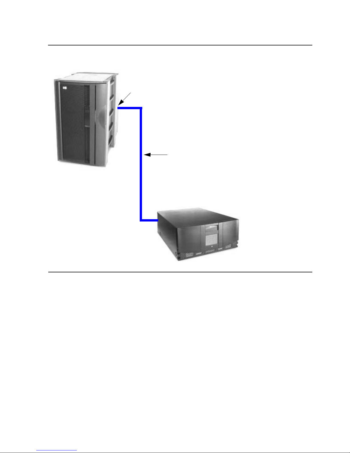
on the NonStop S-series server by a SCSI cable. Figure 1- 1 shows how
the ACL tape drives connect to the NonStop S-series server.
Overview 1-1
Models and Accessories 1-3
Internal Tape Drive 1-3
Magazine 1-4
Power Supply 1-4
Robotics 1-4
Front Panel Indicators 1-6
Page 12
Overview and Features
N1528A and N1529A ACL Tape Drive Installation and User’s Guide —544594-003
1-2
NonStop NS-Series Servers
NonStop N S- Series Servers
An M8201R Fibre Channel to SCSI router must be used to connect the tape drives to
the Fibre Channel ServerNet Adapter (FCSA) on the HP NonStop NS-series server.
For more information on the router, refer to the M8201R Fibre Channel to SCSI Router
Installation and User’s Guide.
Figure 1-1. Hardware Configuration
NonS t op S-Series
Tape Drive
SCSI Cable
ServerNet/DA,
IOMF2 CRU, or
PMF CRU
Server
Page 13
Overview and Features
N1528A and N1529A ACL Tape Drive Installation and User’s Guide —544594-003
1-3
Models and Accessories
Models and Accessories
These auto cartridge loader tape drives are configured with one internal LTO Gen 3
tape drive along with one removable tape cartridge magazine.
Tape Cartridges
The amount of data that can be stored on the LTO Gen 3 tape cartridge can be up to
800 gigabytes ( 2:1 compr ession) . DLTIIItape, DLTIVt ap e, or SD LT m edi a ca rtridg es ar e
not compatible with this tape drive. The size and shape of the tape drive’s media are
similar to those of DLT cartridges in order to make it easy for automation.
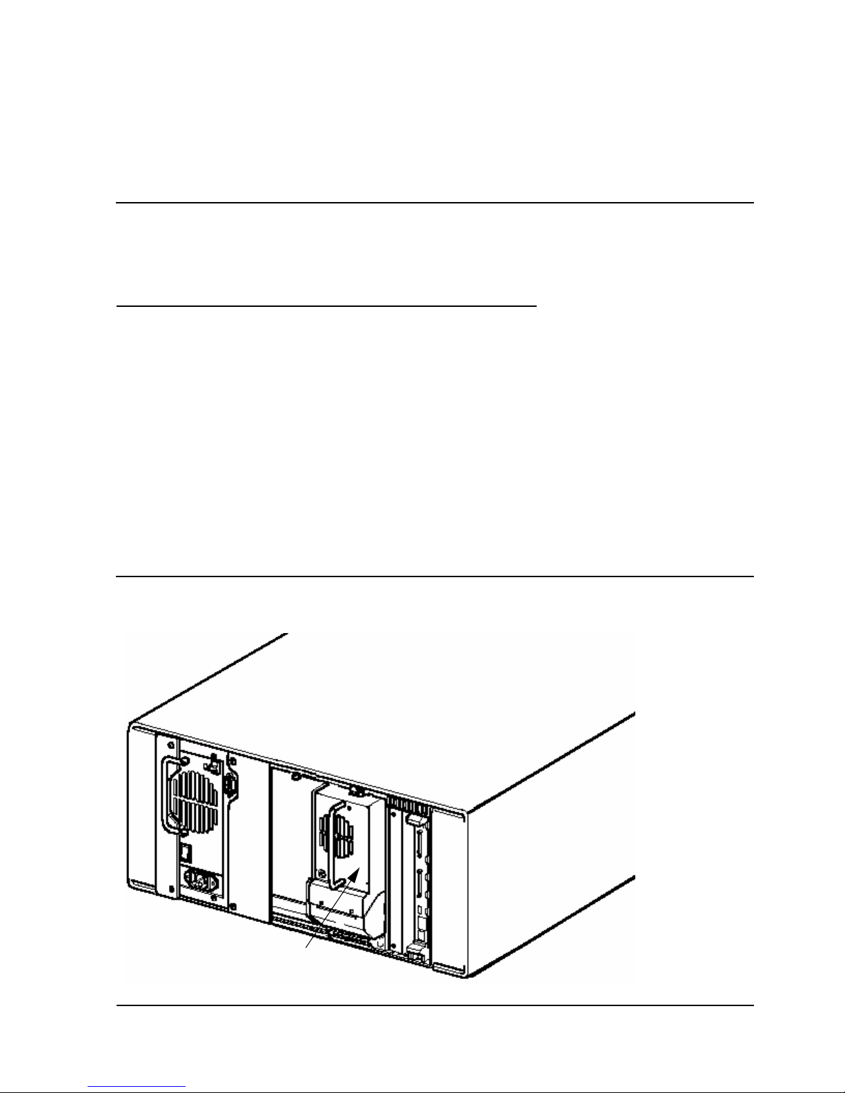
Internal Tape Drive
The ACL units supports a single internal tape drive. The internal tape drive can be hotswapped.
Table 1-1. Models and Slot Capacities
Model Drives Slots LTO
N1528A 1 15 LTO 12.0 TB
N1529A 1 15 LTO 12.0 TB
Figure 1-2. Rear View of Tape Drive
Single Drive
Page 14
Overview and Features
N1528A and N1529A ACL Tape Drive Installation and User’s Guide —544594-003
1-4
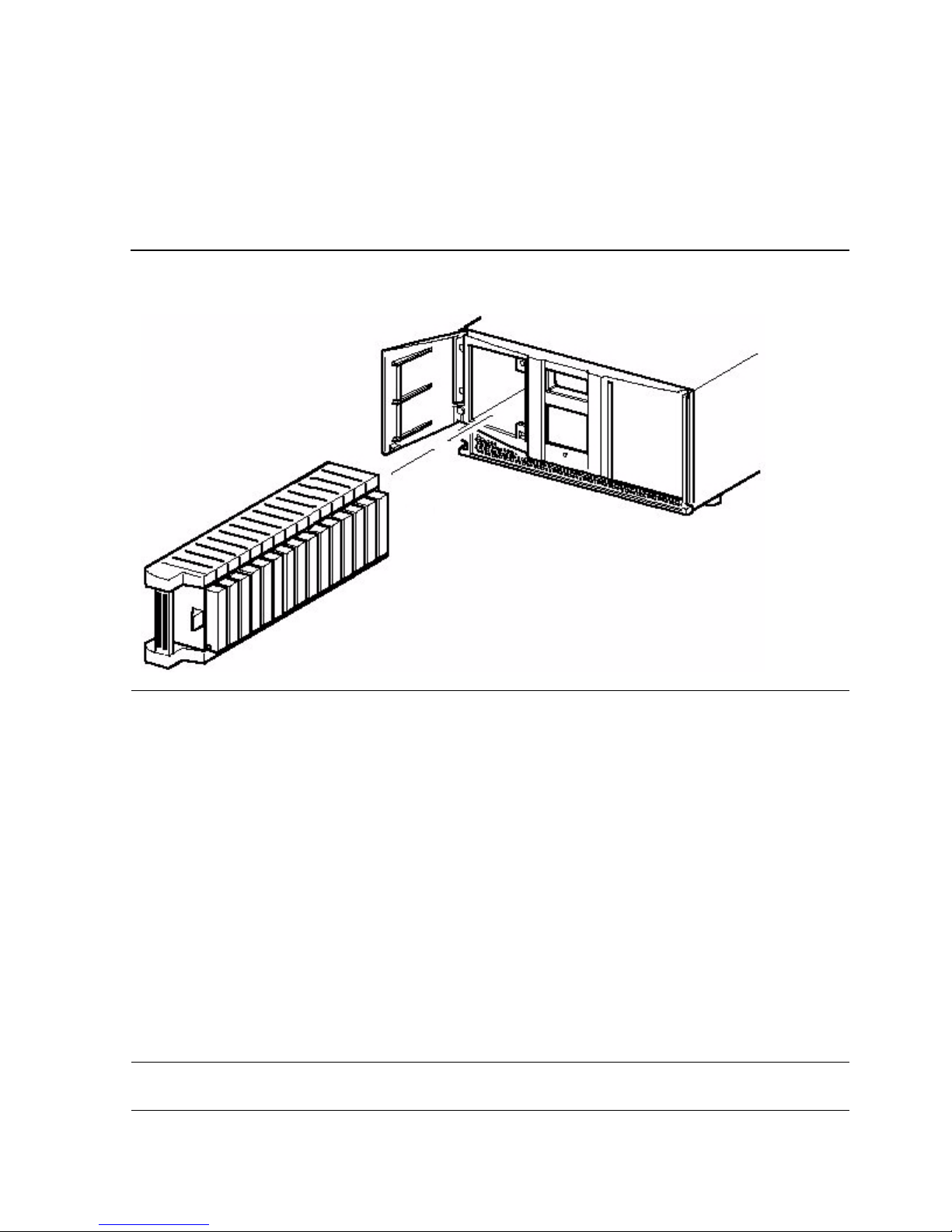
Magazine
Magazine
The ACL units contains one removable tape cartridge magazine that is accessible
through the front left door. The door is opened by using the GUI touch screen on the
control panel.
Power Supply
Power to the ACL units are supplied through an AC connector at the rear panel of the
power supply. The ACL unit’s power is normally controlled from the graphical user
interface (GUI) touch screen; however, a manual power disconnect switch, located at
the rear of the power supply may also be used.
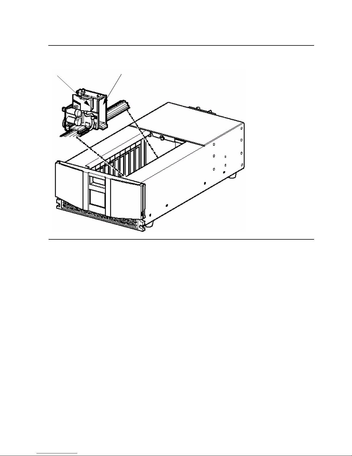
Robotics
The ACL tape drive’s robotics consist of a cartridge shuttle, motor hardware, motor
drives, and other support electronics. These robotics are capable of picking and
placing tapes throughout the tape drive and the tape cartridge magazine.
The cartridge shuttle assembly includes a mounted barcode reader for scanning tape
cartridges installed in the magazine and tape drive.
Figure 1 -3. Tape Ca rtridge Magazine
Note. Both a full barcode reader scan and a physical scan are conducted each time the unit is
initially po w ered up, or ea c h t im e a tape magaz ine is excha nged.
Page 15
Overview and Features
N1528A and N1529A ACL Tape Drive Installation and User’s Guide —544594-003
1-5
Robotics
Figure 1-4. View of Barcode Reader and Shuttle Assembly
Barcode Reader Shuttle
Page 16
Overview and Features
N1528A and N1529A ACL Tape Drive Installation and User’s Guide —544594-003
1-6
Front Panel Indicators
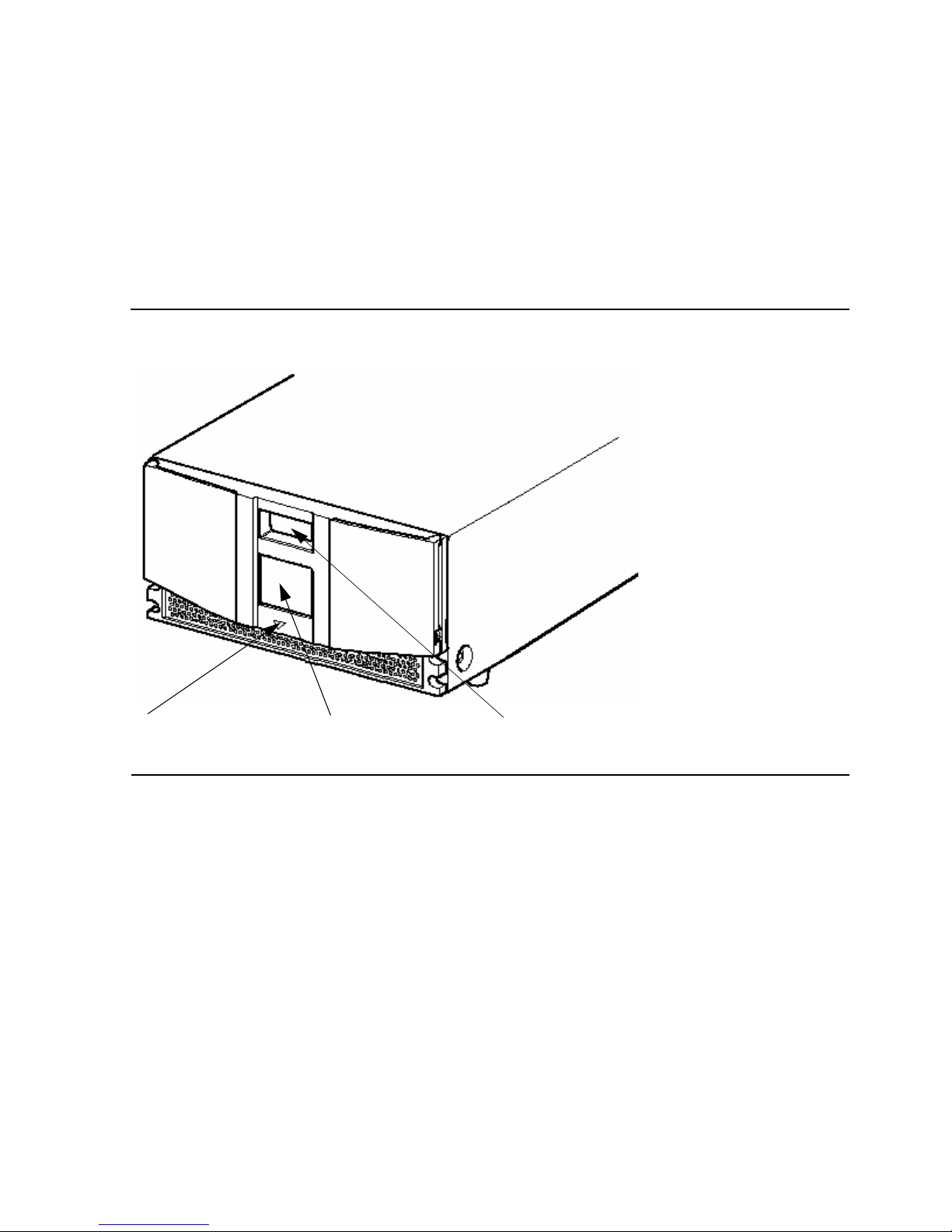
Front Panel Indicators
The ACL tape drive’s front panel indicators consist of:
•
Viewing window - lets you visually check the unit’s internal operations
•
GUI touch screen - manually operated to setup and configure the unit
•
ACL module status LED - displays the unit’s operational status
Figure 1-5. Front Panel Indicators
ACL Status LED GUI Touch Screen Internal Viewing
Window
Page 17
N1528A and N1529A ACL Tape Drive Installation and User’s Guide —544594-003
2-1
2 Setting Up the ACL Tape Drives
This section includes:
Setting Up the N1528A ACL Rackmount Unit
Setting up the ACL rackmount unit requires a template and storage cabinet slide rails
to install the unit in a standard 19-inch rack storage cabinet.
To set up the rackmount model:
1. Ensure that you have adequate space available in the rack.
2. Use the template that is shipped with the unit to mark the location of the mounting
hardware on the mounting rails of the storage cabinet.
Setting Up the N1528A ACL Rackmount Unit 2-1
Setting Up the N1529A ACL Tabletop 2-5
Figure 2-1. N1528A ACL Template
Page 18

Setting Up the ACL Tape Drives
N1528A and N1529A ACL Tape Drive Installation and User’s Guide —544594-003
2-2
Setting Up the N1528A ACL Rackmount Unit
a. Push back the tabs in the top of the template and place them in the correct
holes in the mounting rack. Match up the hole pattern indicated on the sides of
the template with the hole pattern in the mounting rack.
b. Make sure to begin measuring in the correct place. If a unit is already installed
immediately below the planned position of the new unit, then place the
template against the front of the mounting rack and rest it on top of the
previously installed unit.
c. Use the front of the template to mark the attachment points for mounting
brackets, rails, components, or cage nuts on the back of the storage cabinet.
d. Use the back of the template to mark the attachment points for the mounting
brackets, rails, components, or cage nuts on the back of the storage cabinet.
3. Remove the template.
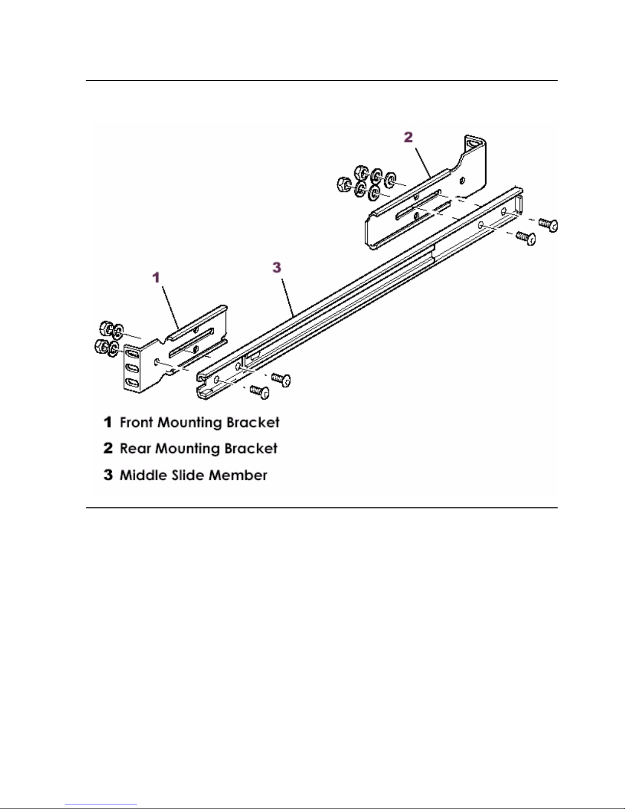
4. Install the slide members for the rackmount unit.
5. If the slide members are already installed, attach the front and rear mounting
brackets to the outer and middle slide members.
Page 19
Setting Up the ACL Tape Drives
N1528A and N1529A ACL Tape Drive Installation and User’s Guide —544594-003
2-3
Setting Up the N1528A ACL Rackmount Unit
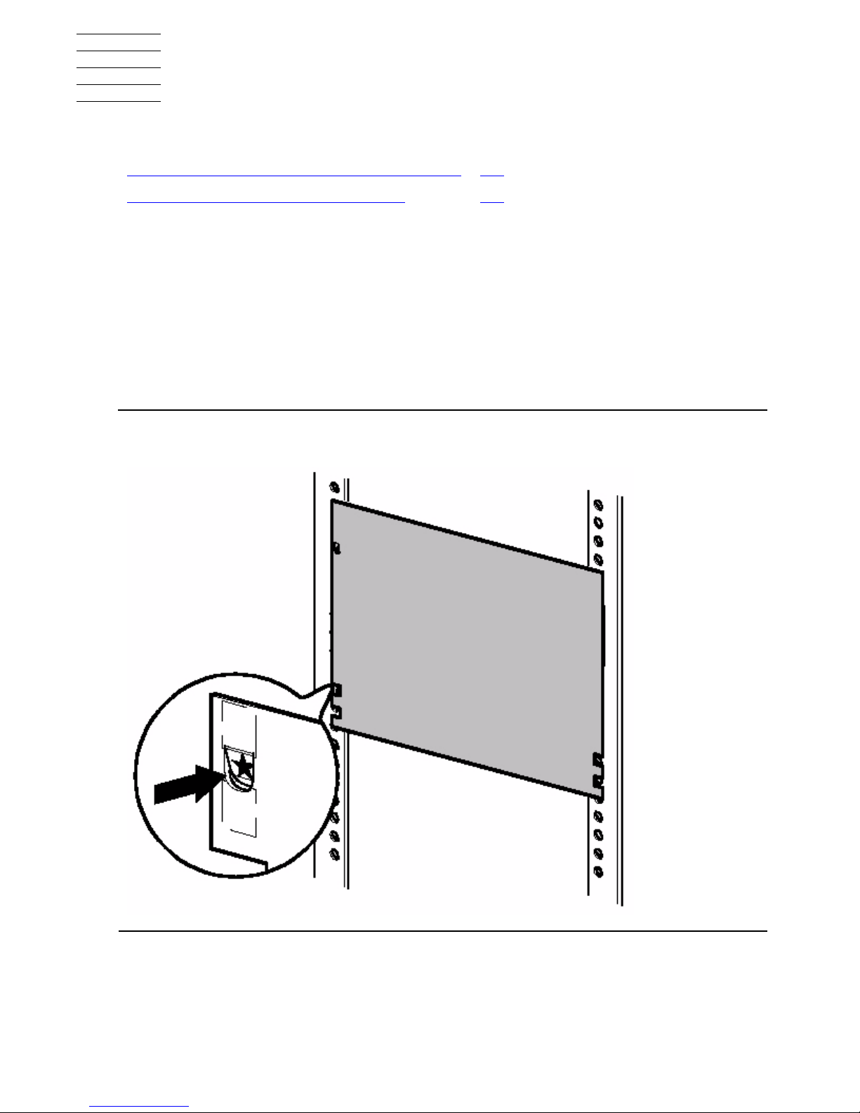
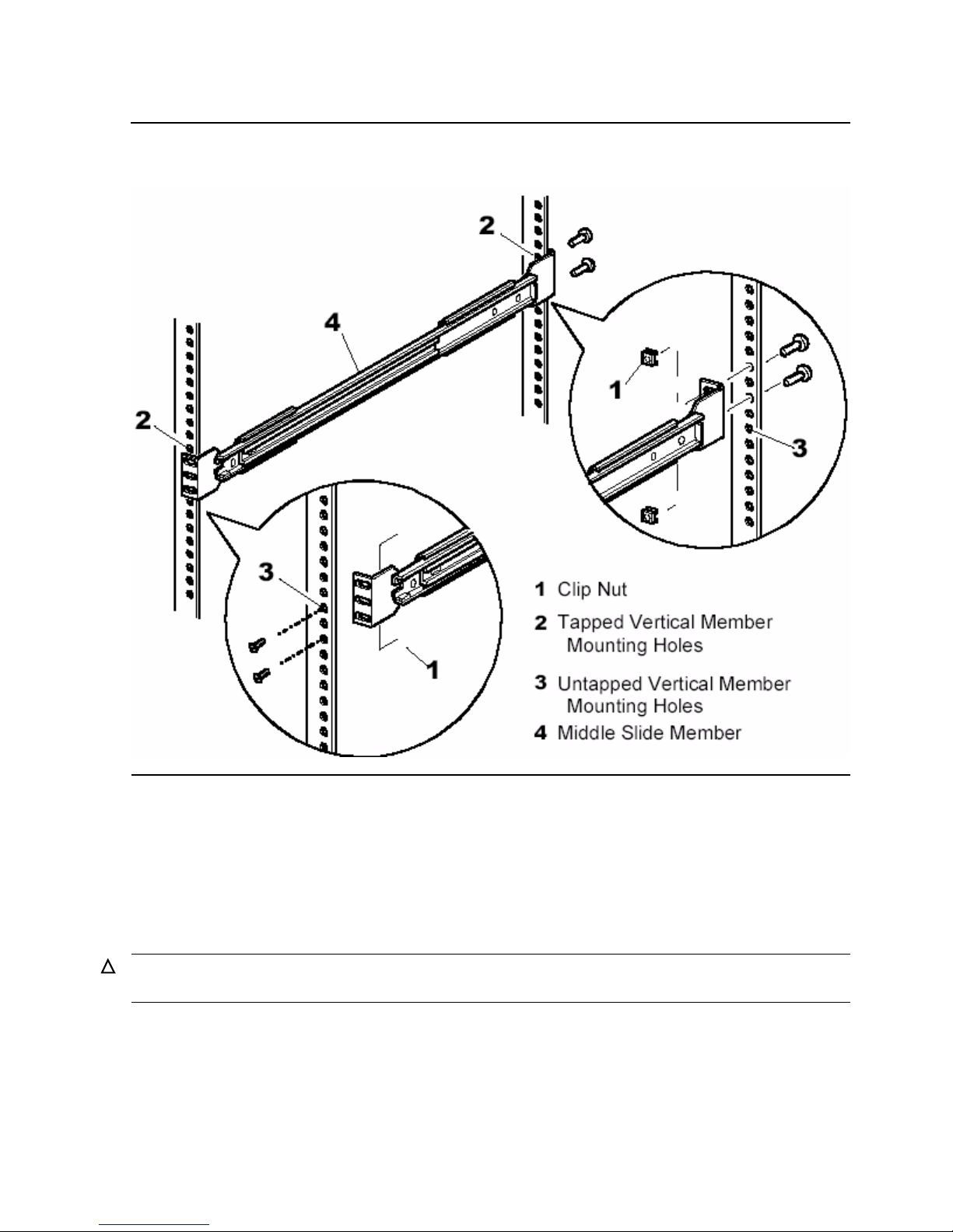
6. Attach the slide members using the supplied fasteners. Install the clip nuts on the
inside of the slide member’s front and back mounting bracket only if the vertical rail
mounting holes are not tapped.
Figure 2-2. Installing the Slide Members
Page 20
Setting Up the ACL Tape Drives
N1528A and N1529A ACL Tape Drive Installation and User’s Guide —544594-003
2-4
Setting Up the N1528A ACL Rackmount Unit
7. Push the middle slide member as far as possible to the front of the slide member
assembly.
8. Install the two clip nuts on each of the rack’s front vertical rails.
9. Confirm that the bearing carrier is in the retained position.
10. Lift the unit and visually align the inner and middle slide members.
11. Verify the ball bearing slide members are located in the front position.
12. Slide the unit completely into the rack until the front panel touches the rack.
13. Remove and discard the tape that holds the door in the latched position, leaving
the door open.
Figure 2-3. Installing Slide Member Fasteners
Caution. It is recommended that the unit be lifted by two people. Do not attempt to lift the unit
by yourself.
Page 21
Setting Up the ACL Tape Drives
N1528A and N1529A ACL Tape Drive Installation and User’s Guide —544594-003
2-5
Setting Up the N1529A ACL Tabletop
14. Attach the unit to the rack using two 10-32 captive thumbscrews that are located
on the lower left and right front panel.
15. Fully tighten the rear-mounting bracket screws.
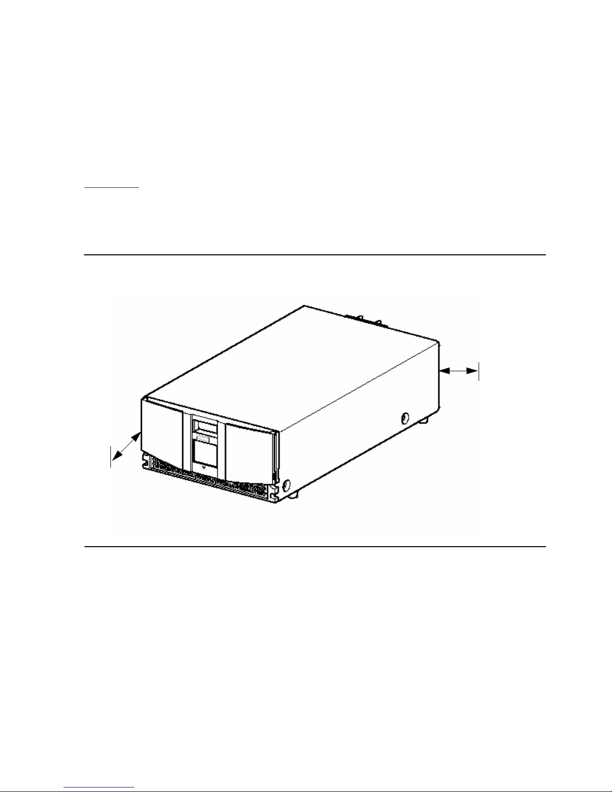
Setting Up the N1529A ACL Tabletop
The N1529A ACL tabletop requires no mechanical assembly for mounting. (See
Figure 2-4.) Place the unit on a desk, table, or other stable horizontal surface. Ensure
that the cooling grills at the front and the fans at the rear of the unit are not obstructed.
Allow 12 inches (30.4 centimeters) of clearance at the front and 6 inches (15.2
centimeters) at the rear of the unit to allow for adequate cooling.
Figure 2-4. Tabletop Model Clearances
6 inches
(15.2
1
2 inches
(
30.4
c
enti-
m
eters)
centimeters)
Page 22

Setting Up the ACL Tape Drives
N1528A and N1529A ACL Tape Drive Installation and User’s Guide —544594-003
2-6
Setting Up the N1529A ACL Tabletop
Page 23

N1528A and N1529A ACL Tape Drive Installation and User’s Guide —544594-003
3-1
3 Installing and Configuring the
ACL Tape Drive for the NonStop SSeries Server
This section includes these topics:
Installation Procedure for New Model
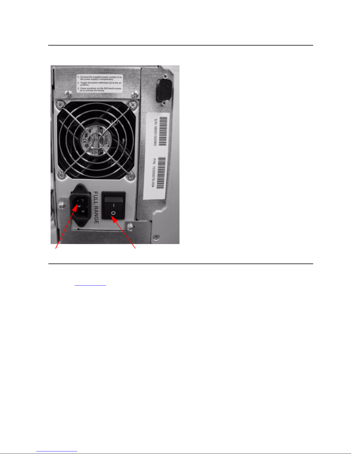
1. Check that the power switch on the tape drive is set to the off position. See
Figure 3-1.
2. Connect the power cord to the tape drive’s AC power receptacle. See Figure 3-1.
3. Make sure the power cord is fully seated.
Installation Procedure for New Model 3-1
Installation Procedure for Old Model 3-5
Configuration 3-9
Note. These AC L units are now shipped in a different type of chassis. Th e ins ta llation
procedure for the new er model is different from the older mo del. If you hav e t he newer model,
please see Installation Proced ure for New Model
for the installa t ion procedu re. F or the
installation procedure for the older model see Installation Procedure for Ol d Model. The
configuration section applies to both types.
Note. Do not attach th e m ale end of the power cord to a power outlet at this time.
Page 24
Installing and Configuring the ACL Tape Drive for the
NonStop S-Series Server
N1528A and N1529A ACL Tape Drive Installation and User’s Guide —544594-003
3-2
Installation Procedure for New Model
4. Connect the NonStop SCSI cable to the SCSI port on the SCSI Converter card.
See Figure 3-2
for the location.
5. Connect the other end of the NonStop SCSI cable to a supported SCSI port on the
server.
You can attach the tape drive to a NonStop S-series server using one of the
following:
•
ServerNet/DA
•
IOMF2 CRU
•
PMF CRU
Figure 3-1. View of Power Switch and AC Power Receptacle
AC Power Receptacle Power Switch
Page 25
Installing and Configuring the ACL Tape Drive for the
NonStop S-Series Server
N1528A and N1529A ACL Tape Drive Installation and User’s Guide —544594-003
3-3
Installation Procedure for New Model
You can use any of the following NonStop SCSI cables:
6. Connect the one end of the VHDCI SCSI cable to the bottom SCSI port on the
SCSI Converter card. See Figure 3-2.
7. Connect the other end of the VHDCI SCSI cable to the bottom SCSI port on the
tape drive.
8. Install the terminator on the top SCSI port of the tape drive. See Figure 3-2.
Table 3-1. NonStop SCSI Cables
Model Number Description
519-003W 3 meter copper SCSI cable
519-015W 15 meter copper SCSI cable
519-020W 20 meter copper SCSI cable
519-023W 23 meter copper SCSI cable
Figure 3-2. Rear View of Tape Drive
Terminator VHDCI SCSI Cable Connect NonStop SCSI Cable Here
Terminator Switch to On
Page 26

Installing and Configuring the ACL Tape Drive for the
NonStop S-Series Server
N1528A and N1529A ACL Tape Drive Installation and User’s Guide —544594-003
3-4
Installation Procedure for New Model
9. Attach the male end of the power cord to an AC power outlet.
10. Toggle the terminator switch to the on position (the terminator switch must be
set to the on position for the NonStop server).
11. Toggle the power switch at the rear of the tape drive to the on position.
12. Press the GUI screen at the front of the tape drive to activate the library.
13. Verify that the drive powers on.
WARNING. The tape drive does not have protection against lightning surges. For this reason,
if you are located in a hig h ris k area, use ex te rnal surge p rot ec t ion rated for use in your
location and be able to h andle the po w er requirem ents of the tape drive enclosure.
Page 27
Installing and Configuring the ACL Tape Drive for the
NonStop S-Series Server
N1528A and N1529A ACL Tape Drive Installation and User’s Guide —544594-003
3-5
Installation Procedure for Old Model
Installation Procedure for Old Model
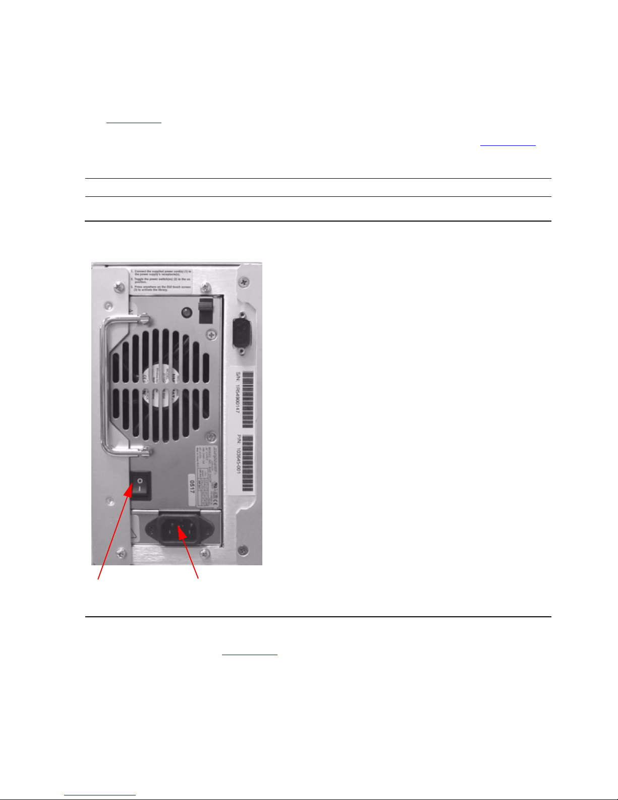
1. Check that the power switch on the tape drive is set to the off position. See
Figure 3-3.
2. Connect the power cord to the tape drive’s AC power receptacle. See Figure 3-3.
3. Make sure the power cord is fully seated.
4. Connect the 68-pin to 68-pin SCSI cable to the top SCSI port on the SCSI
Converter card. See Figure3-5
.
5. Connect the other end of the SCSI cable to a supported SCSI port on the server.
You can attach the tape drive to a NonStop S-series server using one of the
following:
Note. Do not attach th e m ale end of the power cord to a power outlet at this time.
Figure 3-3. View of Power Switch and Power Receptacle
Power Switch AC Power Receptacle
Page 28

Installing and Configuring the ACL Tape Drive for the
NonStop S-Series Server
N1528A and N1529A ACL Tape Drive Installation and User’s Guide —544594-003
3-6
Installation Procedure for Old Model
•
ServerNet/DA
•
IOMF2 CRU
•
PMF CRU
You can use any of the following SCSI cables:
6. Connect one end of the VHDCI 68-pin to VHDCI 68-pin SCSI cable to the top port
below the rear of the internal tape drive. See Figure 3-5.
7. Connect the other end to the bottom SCSI port on the SCSI Converter card. See
Figure 3-5.
8. Install one of the LVD terminators on the top SCSI port of the Library Controller
card. See Figure 3-5.
9. Install the other LVD terminator on the bottom SCSI port below the rear of the
internal tape drive. See Figure 3-4.
Table 3-2. SCSI Cables
Model Number Description
519-003W 3 meter copper SCSI cable
519-015W 15 meter copper SCSI cable
519-020W 20 meter copper SCSI cable
519-023W 23 meter copper SCSI cable
Page 29

Installing and Configuring the ACL Tape Drive for the
NonStop S-Series Server
N1528A and N1529A ACL Tape Drive Installation and User’s Guide —544594-003
3-7
Installation Procedure for Old Model
Figure 3-4. Rear View Below of Internal Tape Drive
SCSI Cable LVD Terminator
Page 30

Installing and Configuring the ACL Tape Drive for the
NonStop S-Series Server
N1528A and N1529A ACL Tape Drive Installation and User’s Guide —544594-003
3-8
Installation Procedure for Old Model
10. Attach the male end of the power cord to an AC power outlet.
11. Toggle the terminator switch to the on position (the terminator switch m ust be
set to the on position for the NonStop server).
12. Toggle the power switch at the rear of the tape drive to the on position.
13. Press the GUI screen at the front of the tape drive to activate the library.
14. Verify that the drive powers on.
Figure 3-5. Rear View of Tape Drive
WARNING. The tape drive does not have protection against lightning surges. For this reason,
if you are located in a hig h ris k area, use ex te rnal surge p rot ec t ion rated for use in your
location and be able to h andle the po w er requirem ents of the tape drive enclosure.
Terminator VHDCI SCSI Cable SCSI Cable Terminator Switc
h
LVD Terminator
Page 31

Installing and Configuring the ACL Tape Drive for the
NonStop S-Series Server
N1528A and N1529A ACL Tape Drive Installation and User’s Guide —544594-003
3-9
Configuration
Configuration
ServerNet/DA
To add the tape drive to the server configuration database, use the SCF ADD TAPE
command to add the tape drive. Before issuing this command, check that the tape
drive is installed properly.
To add the tape drive:
-> SCF
-> ADD TAPE $ACLTAP, SENDTO STORAGE, LOCATION (1,1,51), SAC
1, DEVICEID 5, PRIMARYCPU 0, BACKUPCPU 1
-> START TAPE $ACLTAP
-> STATUS TAPE $ACLTAP, DETAIL
For complete details about the ADD and STATUS commands, including
command syntax, see the SCF Reference Manual for the Storage Subsystem.
PMF CRU
To add the tape drive to the server configuration database, use the SCF ADD TAPE
command to add the tape drive. Before issuing this command, check that the tape
drive is installed properly.
To add the tape drive:
-> SCF
-> ADD TAPE $ACLTAP, SENDTO STORAGE, LOCATION (1,1,50),
DEVICEID 5, PRIMARYCPU 0, BACKUPCPU 1
-> START TAPE $ACLTAP
-> STATUS TAPE $ACLTAP, DETAIL
In this example:
•
The LOCATION attribute specifies the location (group, module, and slot) of
the PMF CRU (adapter) to which the tape drive is attached.
•
The DEVICEID attribute shows the device ID that is configured for the
device. This ID must match the SCSI ID that is physically set in the device.
•
The PRIMARYCPU attribute specifies the processor in which the primary
tape process should execute.
•
The BACKUPCPU attribute specifies the processor in which the tape
process starts its backup process.
For more information about the ADD and STATUS commands, see the SCF
Reference Manual for the Storage Subsystem.
Page 32

Installing and Configuring the ACL Tape Drive for the
NonStop S-Series Server
N1528A and N1529A ACL Tape Drive Installation and User’s Guide —544594-003
3-10
PMF CRU
Page 33

N1528A and N1529A ACL Tape Drive Installation and User’s Guide —544594-003
4-1
4 Operation
This section includes:
Front Panel
The front panel of the ACL units include the left magazine door, a graphical user
interface (GUI) touch screen, an ACL status LED, and a viewing window. See
Figure 4-1.
Front Panel 4-1
Display Screens and Options 4-4
Menu Selections 4-10
Inserting and Removing Tape Cartridges 4-13
Figure 4-1. Front Panel
Left Magazine Viewing
Door Window GUI Touch Screen
ACL Status
LED
Page 34

Operation
N1528A and N1529A ACL Tape Drive Installation and User’s Guide —544594-003
4-2
Magazine Door
Magazine Door
The magazine door has both an electrical release (via the GUI touch screen) and a
manual release. It is always recommended that you open the magazine door using the
GUI touch screen. If the GUI touch screen should fail, you can manually open the door
by pushing a paper clip into the mechanical release at the center of the door.
Indicators
The ACL tape drive’s front panel indicators consist of a GUI touch screen and an ACL
status LED.
Figure 4-2. Magazine Door Mechanical Release
Table 4-1. ACL Front Panel Indicators
Indicator Description
Solid Gre en The ACL is operating corr ec t ly under norm al c onditions.
Flas hing Green The ACL is operating co rrectly; how ev er, a cha nge is
being made via the GUI touch s cr een that inte rrupts the
current ACL operation.
Solid Amber The ACL is in a fault state as indicated by the fault
message on the GUI touch screen.
Magazine Door Release ACL Status LED
Page 35

Operation
N1528A and N1529A ACL Tape Drive Installation and User’s Guide —544594-003
4-3
Initialization Screen
Initia l izatio n Scr e e n
When power is first applied to the ACL tape drives, a series of power-on self test
(POST) diagnostics are performed. After the POST completes, this initialization screen
appears.
Figure 4-3. Initialization Screen
Note. Pressing Continue will display the ACL default screen.
Page 36

Operation
N1528A and N1529A ACL Tape Drive Installation and User’s Guide —544594-003
4-4
ACL Default Screen
ACL Default Screen
After the POST executes successfully and the ACL initialization completes, the ACL
tape drive Default screen appears as shown in Figure 4-4.
The ACL Default screen enables you to select these options:
•
Technical Support Information (HP logo)
•
Magazine Access
•
Move Media
•
LCD Contrast Controls
•
Power
•
Status Online
•
Menu
Display Screens and Options
The ACL GUI touch screen displays graphics and text in the form of easy to
understand messages. Graphics and text messages, along with their functions, are
described in this section.
Figure 4-4. ACL Default Screen
Page 37

Operation
N1528A and N1529A ACL Tape Drive Installation and User’s Guide —544594-003
4-5
Technical Support Information Option
Technical Support Information Option
Selecting the HP logo in the top left corner displays technical support information
specific to HP. See Figure 4-5.
Figure 4-5. Technical Support Information
Note. The HP Global Custo m er Support Center (GCSC) provides technical support for this
product.
Page 38

Operation
N1528A and N1529A ACL Tape Drive Installation and User’s Guide —544594-003
4-6
Access Magazine Option
Access Magazine Option
Selecting this option lets you display the Access Magazine screen. See Figure 4-6.
The Access Magazine option lets you gain access to the left magazine door for tape
cartridge placement or removal.
Move Media
Selecting this option lets you display the Move Media screen. See Figure 4-7. The
Move Media option lets you remove a cartridge from the tape drive, load a cartridge to
the tape drive, or to move cartridges within the ACL.
Figure 4-6. Access Magazine Screen
Figure 4-7. Move Media Screen
Page 39

Operation
N1528A and N1529A ACL Tape Drive Installation and User’s Guide —544594-003
4-7
Move Med ia
These figures illustrate moving a cartridge from the tape drive to a slot in the
magazine:
1. Touch the Source input box or Source Element Type from the Move Media Screen.
The Source input box will change from gray to an active state. See Figure 4-8.
2. Touch the source you want to move, from the Source Element Type selections.
The options available are Drive and Slot.
3. Touch the Destination Input Box on the Move Media Screen. The Destination Input
Box changes from gray to an active state. See Figure 4-9.
Figure 4-8. Move Media Screen (Source)
Figure 4-9. Move Media Screen (Destination)
Page 40

Operation
N1528A and N1529A ACL Tape Drive Installation and User’s Guide —544594-003
4-8
LCD Contrast Controls
4. From the Destination Element Type selections, touch the destination option that
you want to move media to. The options available are Drive and Slot. Keep
selecting the desired destination option until the desired option is displayed in the
Destination Input Box. For example, touch i ng Slot three ti mes displays S lot 3 in the
Destination Input Box.
5. Touch the “Execute Move” button. The ACL robotics move the cartridge from the
Drive to Slot 3.
LCD Contrast Controls
Selecting these options let you increase or decrease the contrast of the LCD display.
Incremental steps are set by adjusting the LCD contrast controls (up and down arrows)
from the upper right corner of the ACL Default screen. Incremental steps can range
from 0 to 31 depending on your preference.
Power
Selecting this option initiates an ACL power-down operation.
Note. The ACL moves the shuttle assembly to the parked position before powering down.
Figure 4-10. Power Down Initiation Screen
Page 41

Operation
N1528A and N1529A ACL Tape Drive Installation and User’s Guide —544594-003
4-9
Status
Status
Selecting this option lets you display the ACL Status screen. You can identify a tape
drive type, view physical tape drive status, tape drive cleaning information, and tape
cartridge information by opening the corresponding areas on the screen.
Online
Selecting this option from the ACL Default screen lets you place the ACL online or
offline.
Note. By default, the ACL aut omati c ally co me s onl ine after a pow er-up initia lization .
Page 42

Operation
N1528A and N1529A ACL Tape Drive Installation and User’s Guide —544594-003
4-10
Menu Selections
Menu Selections
Selecting Menu on the ACL Default screen lets you view, configure, and use the ACL.
The Menu option displays three distinct areas:
•
View System Data
•
Utilities
•
Edit Options
View System Data
The View System Data area lets you select these screens:
•
ACL Options
•
SCSI Options
•
Network Options
•
ACL Info
•
Cartridge Map
ACL Options
Selecting this option lets you view but not modify the ACL settings as defined in the
ACL option of the Edit Options area. Table 4-2
on page 4-11 describe the available
options.
Figure 4-11. Menu Screen
Page 43

Operation
N1528A and N1529A ACL Tape Drive Installation and User’s Guide —544594-003
4-11
View System Data
Table 4-2 below, lists and describes the available ACL options.
Note. You can view the next sequential ACL Options screen by selecting the up arrow. To
return to the previous ACL Options screen, select their Back button to return to the Menu
screen.
Figure 4-12. View ACL Options Screen (Initial Screen)
Table 4-2. View ACL Options
Option Description
ACL Stays Offline After
Power-up Initialization
ACL does not go online after power-up init ialization. You
must select the Online option from the Menu screen on the
GUI touch screen. The default is Disabled.
Auto Pow er-up on
Installed Drive
Enables a tape drive to be automatically powered up (after a
delay) after replacing a tape drive.
Unload Mode Selects the unload mode for ACL tape drives. If Implicit, the
ACL unloads a tape driv e before atte m pt ing to move a
cartridge from that tape drive. If Explicit, the server must
issue a SCSI UNLOAD command to a tape drive before
each MO VE MEDIUM c om m and that rem oves a cart ridge
from that tape drive. The default is Implicit.
Total Reserved Slots Lets you rem ov e from use a specified number of slo ts at th e
rear of the magazine . The default is 0.
Auto Clean Mode Lets you enable an automatic cleaning cycle. To use this
option, you must have reserved a slot for a cleaning
cartridge us ing the Total Reserved Slots optio n. Th e default
is Disabled.
Page 44

Operation
N1528A and N1529A ACL Tape Drive Installation and User’s Guide —544594-003
4-12
View System Data
Drive and Slot Numbering Lets you specify whether SCSI elements in the ACL
displays with either zero-based or one-based. This affects
the GUI tou c h s c reen, not the actual SCSI element
address es . Th e default is on e based.
ACL Mode Lets you set the robotics operating mode to Random or
Sequen tia l. T he default is Random.
Seque ntial Mo de Lets you sel ec t a nor m al or rec ircu late frequency mod e. T he
default is N ormal. (Only av ailable if ACL Mode is se t to
Sequential).
LCD Cont ras t Adjust The LCD c ont rast controls let you inc rease or de c rease the
contrast of the LCD display. The increment steps are set by
adjustin g th e LCD Contrast Adjus t op t ion from the A C L
option. Inc remental steps c an range from 0 to 31 depending
on your preference.
Barcode Label Size Lets you limi t the maximu m num ber of characters of th e
barcode label. Possible settings are 1 through 8. The default
is 8.
Barcode Label Alignment Lets you spe c ify t he alignme nt of a barcode lab el. The
options a re Left to Right. W hen used in co njunction w ith th e
label size option, this option strips unwanted trailing
characters (left alignment) or lea ding charact ers (right
alignment). The default is Left Align.
Barcode Label Che c k
Digit
Lets you spec if y wh eth er t o ena ble or di sa ble t he v eri fi ca ti on
of a check digit character in the barcode label. The default is
Disabled
Barcode R eader Lets you specify whet her the barcode reader w ill retry
reading b arc ode labels . Th e default is Ret ries Enabl ed.
Module Configuration Lets you specify the ACL Module Configuration. Three
options a re av ailable:
•
Standalone - Used when the AC L contains a sin gle
module
•
Master - U s ed to select th e m odule in a m ult i-m odule
ACL
•
Slave - Used to select the other modules in a multimodule ACL
Table 4-2. View ACL Options
Option Description
Page 45

Operation
N1528A and N1529A ACL Tape Drive Installation and User’s Guide —544594-003
4-13
Inserting and Removing Tape Cartridges
Inserting and Removing Tape Cartridges
The magazine must be removed from the ACL in order to remove or insert tape
cartridges. Make sure the slot you want to use is not already reserved for a tape
cartridge that is now in a tape drive. The safest way to do this is to unload all tape
drives before removing a magazine. Yo u can unload the tape drive either through your
host system software or by using the Move Media option on the Default screen.
Removing the Magazine
You must manually remove the ACL magazine. To access the magazine, use the
Magazine Access option on the Default Screen. This option lets you open the left
magazine door. Af ter opening the maga zine door, pull the magazi ne ou t and away fr om
the ACL chassis.
Inserting Cartridges into the Magazine
A full magazine is sho wn in Figure 4-13. The lowes t numb ered ta pe car tridge slo t is the
one closest to the front of the magazine.
Insert a tape cartridge so that the barcode labels are facing outward.
Note. Handle an d s t ore tape cartrid ges in a clean, dust-free en v ironment.
Page 46

Operation
N1528A and N1529A ACL Tape Drive Installation and User’s Guide —544594-003
4-14
Barcode Labels
Barcode Labels
Figure 4-14 show you how to install a barcode label onto a tape cartridge.
LTO Cartridge Media
The following are tips to ensure maximum LTO cartridge media performance and life:
1. Place labels only in the recessed area, just above the write protection switch (See
Figure). Never place labels on the top, bottom sides or rear of the cartridge, they
can cause loader faults and interfere with normal operations. Such labels can
come off inside the equipment causing damage.
2. Always inspect cartridges for incorrect or improperly attached labels.
3. Never erase information on a cartridge label, always replace the label.
Figure 4-13. Tape Magazine With Tape Cartridges Installed
Page 47

Operation
N1528A and N1529A ACL Tape Drive Installation and User’s Guide —544594-003
4-15
Barcode Labels
Note. Barcode labels may be placed on the m edia with th e alphanum eric charac te rs on the
left or the right.
Figure 4-14. Barcode Label Installation (LTO)
Page 48

Operation
N1528A and N1529A ACL Tape Drive Installation and User’s Guide —544594-003
4-16
Barcode Labels
Page 49

N1528A and N1529A ACL Tape Drive Installation and User’s Guide —544594-003
5-1
5 Maintenance
This section includes:
Manually Running a Cleaning Cartridge
1. From the GUI screen, select the Magazine Access button.
Manually Running a Cleaning Cartridge 5-1
Note. Clea ning sh ould only be done when t he ACL uni t displ ays a mess age in f ormin g y ou that
cleaning is needed.
Caution. A manual cleaning can be done but the tape cartrid ge must be un loaded ma nually
via the cont rol panel using th e ex ecute mo v e option. This is not a recom mended option.
Figure 5-1. Selecting the Magazine Access Button
Page 50

Maintenance
N1528A and N1529A ACL Tape Drive Installation and User’s Guide —544594-003
5-2
Manually Running a Cleaning Cartridge
2. Open the left magazine door by pressing the Left magazine button.
Figure 5-2. Pressing the Lef t Mag azine Button
Page 51

Maintenance
N1528A and N1529A ACL Tape Drive Installation and User’s Guide —544594-003
5-3
Manually Running a Cleaning Cartridge
3. Place a cleaning cartridge into the magazine as shown in Figure 5-3.
4. Close the left magazine door.
Figure 5-3. Cleaning Cartrid ge Placed Into Ma gazine
Page 52

Maintenance
N1528A and N1529A ACL Tape Drive Installation and User’s Guide —544594-003
5-4
Manually Running a Cleaning Cartridge
5. Press the Move Media button.
Figure 5-4. Pressing the Move Media Button
Page 53

Maintenance
N1528A and N1529A ACL Tape Drive Installation and User’s Guide —544594-003
5-5
Manually Running a Cleaning Cartridge
6. Press the Execute Move button.
Figure 5-5. Pressing the Execute Move Button
Page 54

Maintenance
N1528A and N1529A ACL Tape Drive Installation and User’s Guide —544594-003
5-6
Manually Running a Cleaning Cartridge
The ACL will now load the cartridge into the drive.
Figure 5-6. Loading Cartridge into Drive
Page 55

Maintenance
N1528A and N1529A ACL Tape Drive Installation and User’s Guide —544594-003
5-7
Manually Running a Cleaning Cartridge
7. After about 90 seconds, press the Move Media button.
Figure 5-7. Pressing the Move Media Button
Page 56

Maintenance
N1528A and N1529A ACL Tape Drive Installation and User’s Guide —544594-003
5-8
Manually Running a Cleaning Cartridge
8. Press the Execute Move button.
Figure 5-8. Pressing the Execute Move Button
Page 57

Maintenance
N1528A and N1529A ACL Tape Drive Installation and User’s Guide —544594-003
5-9
Manually Running a Cleaning Cartridge
The ACL will now unload the cartridge from the drive.
Figure 5-9. Unloading Cartridge from Drive
Page 58

Maintenance
N1528A and N1529A ACL Tape Drive Installation and User’s Guide —544594-003
5-10
Manually Running a Cleaning Cartridge
9. After the ACL has unloaded the cartridge, press the Magazine Access button.
Figure 5-10. Selecting the Magazine Access Button
Page 59

Maintenance
N1528A and N1529A ACL Tape Drive Installation and User’s Guide —544594-003
5-11
Manually Running a Cleaning Cartridge
10. Open the left magazine door by pressing the Left magazine button.
11. Take the cleaning cartridge out, and then close the magazine door
Figure 5-1 1 . Pressing the Lef t Mag azine Button
Page 60

Maintenance
N1528A and N1529A ACL Tape Drive Installation and User’s Guide —544594-003
5-12
Manually Running a Cleaning Cartridge
Page 61

N1528A and N1529A ACL Tape Drive Installation and User’s Guide —544594-003
6-1
6 Troubleshooting
This section includes:
Stuck Tape Removal Procedure
1. Remove the shoe kit from the rear of the chassis. Two screws will need to be
unscrewed with a flat-head screwdriver. See Figure 6-1 for the location of the
screws. After the screws are unscrewed, gently slide the shoe kit out of the
chassis.
Stuck Tape Removal Procedure 6-1
Platform Problems 6-5
Error Recovery 6-5
Error Recovery Procedures 6-7
Fault Symptom Codes (FSCs) 6-7
Note. The shoe k it a s se m bly is “hot sw appable.” The unit does not have to be pow ered off to
do this proced ure.
Figure 6-1. Location of Screws on Shoe Kit
Screws
Page 62

Troubleshooting
N1528A and N1529A ACL Tape Drive Installation and User’s Guide —544594-003
6-2
Stuck Tape Rem oval Proce dure
2. Disassemble the shoe kit from the brick. There are four screws (two on each side)
on the shoe kit that will need to be removed. See Figure 6-2 for the location of the
screws.
Figure 6-2. Location of Screws on Shoe Kit
Screws
Page 63

Troubleshooting
N1528A and N1529A ACL Tape Drive Installation and User’s Guide —544594-003
6-3
Stuck Tape Rem oval Proce dure
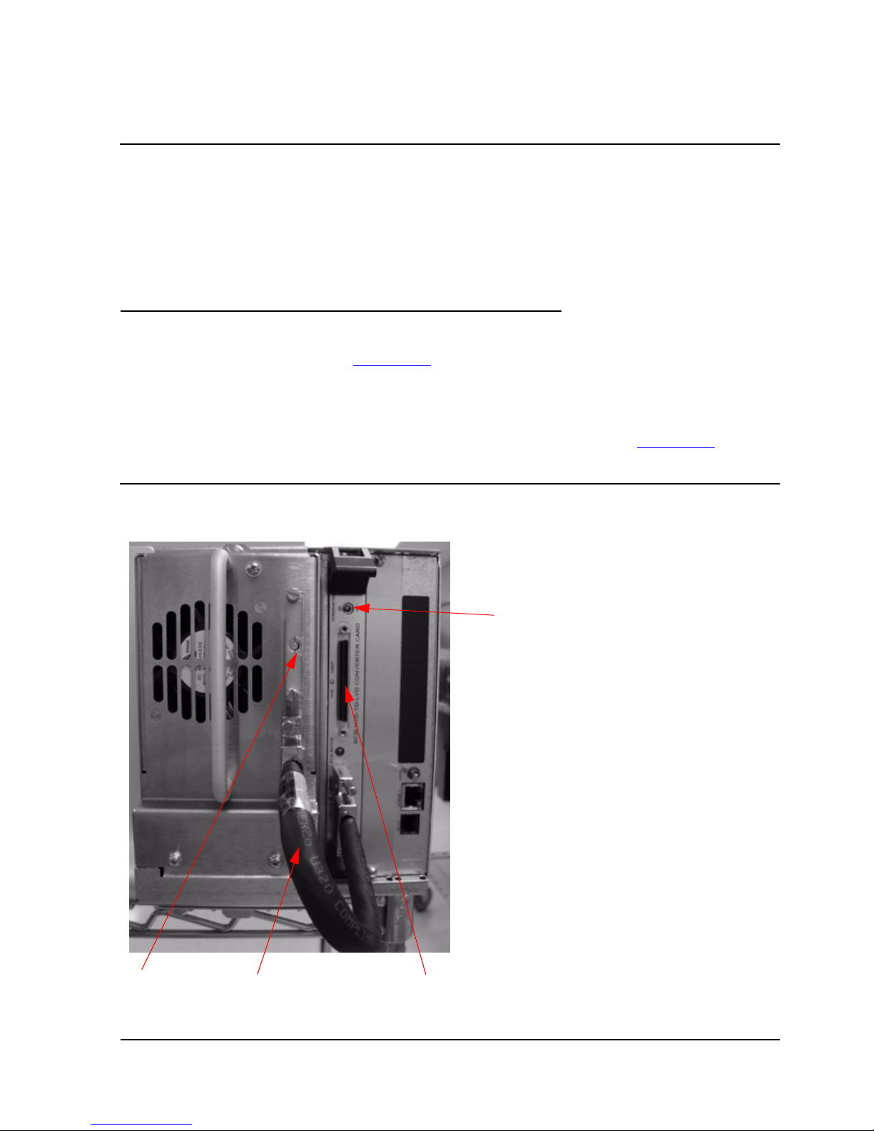
3. Unplug the following cables from the brick:
a. DC power cable
b. SCSI cable
c. SCSI ID cable
See Figure 6-3 for the location of the cables.
4. Place the brick on the side with the front of the brick facing towards the left as
shown in Figure 6-4
.
5. Turn the RD Thumbwhee l (shown in Figure 6-4
) by hand toward the back of the
drive as far as possible (there is no hard stop, but the wheel will begin to spring
back). This positions the grabber into the parking position. Note that the grabber
may already be positioned in the parking position.
6. Using a T-10 Torx driver, rotate the front reel motor clockwise as far as possible.
This unthreads the tape. The front reel motor will stop rotating clockwise when the
tape is completely unthreaded and the tape leader is successfully parked. If a
significant length of tape is threaded, this step could take a long time.
7. Turn the RD thumbwheel (shown in Figure 6-4
) by hand toward the front of brick
until the cartridge is fully ejected. There will be some resistance as the cartridge
Figure 6-3. Location of Cables
DC Power Cable SCSI Cable SCSI ID Cable
Page 64

Troubleshooting
N1528A and N1529A ACL Tape Drive Installation and User’s Guide —544594-003
6-4
Stuck Tape Rem oval Proce dure
comes free of the magnet. This will need to be overcome to get the cartridge in the
fully ejected position.
8. Remove the cartridge by hand.
9. Reassemble the shoe kit back onto the brick.
10. Gently place the shoe kit back into the chassis.
Carefully tighten the screws on the shoe kit with a flat-head screwdriver, do not
tighten them too tight. See Figure 6-1 on page 6-1 for the location of the screws.
Figure 6-4. LTO Tape Drive (Brick)
RD Thumbwheel Access
Rear of
Brick
Front of
Brick
Front Reel Motor Access
T-10 Torx Driver
Page 65

Troubleshooting
N1528A and N1529A ACL Tape Drive Installation and User’s Guide —544594-003
6-5
Platform Problems
Platform Problems
An incorrect installation or configuration can cause platform problems. In this case, the
unit appears to be operating normally, but no data can be interchanged. You also might
or might not get an error code on the Graphical User Interface (GUI) touch screen. To
identify an error caused by this type of problem, check your installation and
configuration se tup. S ee Inst alli ng an d Confi g uring the A CL Tape Drive for th e NonSt op
S-Series Server on page 3-1 for information on how to correctly install and configure
the unit.
General drive errors usually result from a miscommunication between the ACL and
tape drive or a mechanical malfunction within the ACL. Both platform problems and
general drive errors display an error message and a Fault Symptom Code (FSC) on
the GUI touch screen. Use an FSC to report errors to your service provider, or in some
cases, to determine a recovery procedure.
Error Recovery
Figure 6-5 on page 6-6 outlines the recommended steps for error recovery. You should
follow this chart in all cases.
Error Recovery Procedures (ERPs) are listed in detail in Table 6-1 on page 6-7. FSCs
are listed in Table 6–2 along with their related ERPs.
Page 66

Troubleshooting
N1528A and N1529A ACL Tape Drive Installation and User’s Guide —544594-003
6-6
Error Re covery
Figure 6-5. Troubleshooting Flow Cha r t
Page 67

Troubleshooting
N1528A and N1529A ACL Tape Drive Installation and User’s Guide —544594-003
6-7
Error Recovery Procedures
Error Recovery Procedures
Table 6-1 lists ERPs for errors reported on the GUI touch screen of the ACL. This list
includes only procedures that can be safely performed by an end user.
Fault Symptom Codes (FSCs)
FCSs that appear on the GUI touch screen are described in the below tables. A
descriptive message and instructions for clearing the fault accompany each FSC. If a
fault persists, look up the FSC in Table 6-1 on page 6-7 to determine the error recovery
procedure or to report it to your service provider.
Table 6-1. Error Recovery Procedures
ERP Code Procedure/Description
C Cycle pow er to the AC L us ing the Power option on t he GUI
touch sc reen. Wait 30 seco nds to powe r on again.
D Turn off power to th e AC L and insp ec t co nnectors a nd
cables.
F Invalid operat ion. Select parameters correctly and try again.
G Call Technical Support.
Table 6-2. Fault Symptom Codes
Message FSC ERP
Novram Update Error 0306 G The nonvolatile configuration area in flash
memory could not be updated
(programming erro r).
Barcode N ot Ac t iv e
Error
0501 D, G C at as t rophic Smx operating sy stem error
- task creation error, unexpected error.
OS Task Exit Error 0902 G SmxNet (Et hernet, Web TLC) task error -
server spawn error, TCP/IP fatal error.
Invalid Ethernet
(MAC) Ad dress
0A01 F The ACL's Ethernet (MAC) address
stored in the nonvola t ile c onfiguration is
not valid - the last 3 octets are either 0:0:0
or 255:255:2 55.
Invalid IP Subnet
Mask
(255.255.255.255)
0A02 F The Ethernet subnet mask stored in the
nonvolatile configuration is not valid -
255.255.255.255.
SCSI Firm w are Error 100 1 D, G Internal SC SI task processing error -
unexpec t ed state or hard w are status.
SCSI FIFO Empty 1002 D, G T he SCSI con t roller data FIFO is empty
but shou ld c ontain more dat a by t es .
Page 68

Troubleshooting
N1528A and N1529A ACL Tape Drive Installation and User’s Guide —544594-003
6-8
Fault Symptom Codes (FSCs)
SCSI FIFO Error 1003 D, G The SC SI controll er data FIFO sh ould be
empty but still contains data bytes.
SCSI Gro s s E rror 100 4 C, D, G The SCSI controller d et ec t ed a gross
error condition - invalid SCSI bus phase
or DMA error.
Illegal SCSI Cnt Cmd 1005 C, D, G Either an invalid command was sent to
the SCSI controller, or the controller was
not in the correct mod e.
SCSI Inva lid Elemen t 1007 D, G Int ernal SCSI task processing error -
invalid element type w as detected.
SCSI Invalid Int. 1009 D, G The SCSI controller posted an invalid
interrupt stat us .
Loader Not Ready 2004 C, G Fail to fetch, stow, scan, move pas s t hru,
Or when loader dete c ts inv alid comma nd,
aborts command.
Doo r O pen ( status
only)
2009 F Door is fo rc e opened or door sensor
failed.
Cart Inaccessible 200 C F For an LTO, indicates th e ta pe is not
ejected . Cartridge in driv e is not
accessible from changer .
Drive In Error 200D C, G A general drive error detect ed by control
task.
No Magazine 200E F Cannot move, element not installed, from
changer.
Removal Prevented 200F F Receive medium prevent removal fro m
drive for a fet c h.
Ctl. Firmw are Error 2010 C, G Int ernal inter tas k p roc essing error.
Unexp ec ted event. SMX send or rec eive
error.
Drive Time-out Error 2030 C, G C annot com m unicate with drive.
Drive Code Update
Command Error
2080 C, G Update code from SCSI or from TAPE
failed.
Move Command
Failure
2081 C, G Move command from / to drive slot failed,
detected by control task.
Open Mail Slot Fault 2090 C, G Door open sensor time-out detected when
open door.
Open Left Door Fault 2091 C, G Door open sensor time-out detected when
open door.
Open Right Door Fau lt 2092 C, G Door open sensor time-out detec te d whe n
open door.
Table 6-2. Fault Symptom Codes
Message FSC ERP
Page 69

Troubleshooting
N1528A and N1529A ACL Tape Drive Installation and User’s Guide —544594-003
6-9
Fault Symptom Codes (FSCs)
Open Doors Fault 2093 C, G Door open sensor time-out detected when
open door.
Open Handle Fault 2094 C, G F ailed to ope n handle.
No IP Addr es s F ound 20a0 C, G SMC route r fa iled to get an IP address.
No IP Address Mode
Fault
20a1 C, G SMC router failed to detected static or ip
address Mode.
Unknown exchange
for the async
message
20b0 C, G U nexpecte d ex c hange det ec t ed when
process M essages .
Drive In Error 20c0 C, G Control failed to set SCSI id.
Drive In Error 20c1 C, G Control failed to installed drive.
Drive In Error 20c0 C, G Control failed to set SCSI id.
Drive In Error 20c1 C, G Control failed to installed drive.
Motor Fault Condition 3000 C, G One of the motors has been disabled and
could not be re-enabled.
Picker Tach Errors 3002 C, G Pi c ke r Tach errors were detected whe n
checking slots.
Bin Fetch F ailure 3001 C, G Loader fai led to fetch a ca rt ridge from a
bin.
Drive Fetch Failure 3013 C, G Loader failed to fetch a cartridge from the
drive.
Drive Time-out F ailure 3015 C, D, G Loader det ec ts unload command tim e-
out.
Drive Status Failure 3016 C, D, G Detected driv e error from fe tch, stow and
wait fo r handle ok drive op erati on.
Drive In Flu x Time-out 3 017 C , D, G Time-out wait ing for drive t o c lear the flux
status.
Driv e Load Retry
Failed
3018 C, G LTO drive fail to load, detected in drive
task.
Driv e OpenDoo r
Failed
3019 C, G Failed open door.
Drive Close Door
Failed
301A C, G Fai led close driv e door.
Drive Communication
Error
301B C, D, G Intertask se nd, receive fa iled.
Drive Get General
S tatus F ail
301C C, D, G Drive communication failed.
Drive Get Status 3 Fail 301D C, D, G NOT USED
Table 6-2. Fault Symptom Codes
Message FSC ERP
Page 70

Troubleshooting
N1528A and N1529A ACL Tape Drive Installation and User’s Guide —544594-003
6-10
Fault Symptom Codes (FSCs)
Undefin ed C onfig 3020 C, G In loader, unexpected co nf ig, not a
Thunder or Lightning.
Orphan Cartridge n ot
flowed
3030 C, G The loader could not successfully stow an
orphan cartridge to a bin.
Chassis S/N
Mismatch. Previous
S/N retained
3031 G The serial number scanned from the
barcode label does not m at c h t he value
stored in nonvolatile memory.
Chassis S/N
Character count is not
correct
3032 G A valid serial number ba rc ode label co uld
not be read.
Chassis S/N did not
scan
3033 G A valid serial number ba rc ode label co uld
not be read
Chassis S/N save
operation failed
3034 G The serial number scanned from the
barcode label could not be saved to
nonvolatile memory.
Motor Firm w are Error 3040 C, G T he loader task det ected an unexpecte d
status and could not recover (internal
target error).
Loader Received
Invalid Com mand
3041 C, G The loader task received an unexpected
command and cou ld not recove r (int ernal
target error).
Motor Firm w are Error 3042 C, G T he loader task det ected an unexpecte d
status and could not recover (internal
target error).
Missing M agazine 3050 F In diag, no magazine installed fo r diag to
run.
No Cartridges In ACL 3051 F No ca rtr idge availa ble for diag to run.
Too Many Cartridges 3 052 F Unable to run cart or drive cycle, loader is
full with cartridges.
Need 1 Drive
Minimum
3054 F No available driv e t o run diag.
Invalid Magazine Type 3057 F Unsupported Magazine type detected.
Magazine Type
Change Not Handled
3058 F Unsupported magazine type detected.
Drive Typ e Not
Supported
3059 F Unsupported drive type detected.
Diag Fetc h, D riv e not
loaded
305b F Diag: No cartridge present for a fetch.
Diag Time-out waiting
for drive empty, ready
305d F Fetch, time-out waiting for drive unload.
Table 6-2. Fault Symptom Codes
Message FSC ERP
Page 71

Troubleshooting
N1528A and N1529A ACL Tape Drive Installation and User’s Guide —544594-003
6-11
Fault Symptom Codes (FSCs)
Invalid bin number 305f F Invalid bin numbe r detected in diag.
Zone Sequence Err or 3 060 C , G Ejec t co m m and time-out.
Driv e 0 Eject Fa iled 3074 C, G Eject command time-out.
Drive 1 Eject Fail 3075 C, D, G Eject command time-out.
Drive 2 Eject Fail 3076 C, D, G Eject command time-out.
Diag get drive 0 status
failed
3078 C, D, G Failed to get drive status, communication
error.
Diag get drive 1 status
failed
3079 C, D, G Failed to get drive status, communication
error.
Diag get drive 2 status
failed
307a C, D, G Failed to get drive status, communication
error.
Diag get drive 3 status
failed
307b C, D, G Failed to get drive status, communication
error.
Drive Stow Failed,
Media Re tu rned to
Source
3082 F The drive detected a wrong cartridge and
the cartridge has be en returned to its
orign.
Drive Stow Failed,
Media Remains in
Drive
3083 F The drive detected a wrong cartridge but
the cartridge could not be returned to its
origin.
UnSupported Driv e
For Requ es t ed
Operation
3084 F Unsupported drive type.
No Retry On
Fetch/Stow
308F F The loader ret ried an operation and
retries were disabled.
Picker Jam m ed 3100 C , G The pic k er jammed during loader
initialization.
Picker Jam m ed 2 3102 C, G T he picker jam m ed during a bin stow
operation.
Picker Jam m ed 3 3103 C, G T he picker jam m ed during a bin stow
operation.
Picker Jam m ed 4 3104 C, G T he picker jam m ed during a bin stow
operation.
Picker Jam m ed 5 3105 C, G T he picker jam m ed during a bin stow
operation.
Picker Jam m ed 6 3106 C, G T he picker jam m ed during a bin stow
operation.
Picker Jam m ed 7 3107 C, G T he picker jam m ed during a pas s t hru
fetch operation.
Picker Jam m ed 8 3108 C, G T he picker jam m ed during a pas s -t hru
fetch operation.
Table 6-2. Fault Symptom Codes
Message FSC ERP
Page 72

Troubleshooting
N1528A and N1529A ACL Tape Drive Installation and User’s Guide —544594-003
6-12
Fault Symptom Codes (FSCs)
Picker Jam m ed 11 310B C, G The pic ker jammed during a drive fetch
operation.
Picker Jammed on
Stow
310F C, G The pic k er jammed on a stow ope ration.
Picker retries
Exceede d 1
3111 C, G Picker retries exceeded during a pass-
thru fetc h operati on.
Picker Retries
Exceede d 3
3113 C, G Picker retries exceeded during a bin stow
operation.
Picker Retraction
Error
3115 C, G T he picker did not retrac t du ring a bin
check operation.
Shuttle Jam med 3 200 C , G The sh ut t le c ould not rea c h t he ta rget
location.
Rotary Jammed 3300 C, G The rotary track could not reach the target
location.
Shuttle on Wrong Side
Of The Rotar y
3301 C, G T he zone ind ic at ors show th at t he s huttle
is backwa rds on the rotar y tra c k d uring
power-up initialization.
Pass through Elevator
Jammed
3400 C, G T he pass-thru sh ut t le c ould not rea c h th e
target location.
Vertical Elevator
Jammed
3500 C, G T he vertical elev ator could not reach th e
target location
All Sl ots Emp t y 5011 F There are no ca rtri dges ins tall ed in any of
the res erved cl eaning s lots .
Already Loaded 5014 F The cleaning operation failed because the
drive already has a ca rt ridge inserted.
Expired C lean'g Cart 5015 F The clean ing operat ion failed due to an
expired c leaning car tr idge.
Not a Clean'g Cart 5016 F The cleaning operation failed because the
loaded cartridge is not a cleaning
cartridge.
Time-out Error 5035 C, D, G The cleaning operation failed because the
drive timed out.
move Command Fail 503B F A front panel move operation failed.
Clean Operation
Time-out
503C F The cleaning operation failed because the
drive timed out.
Drive Status Fail 503D F The cleaning operation failed because the
ACL coul d not retrieve driv e status.
Command respon se
from unexpected
source
7001 D, G A command response was received from
a task to whic h a c om mand ha d not been
sent.
Table 6-2. Fault Symptom Codes
Message FSC ERP
Page 73

Troubleshooting
N1528A and N1529A ACL Tape Drive Installation and User’s Guide —544594-003
6-13
Fault Symptom Codes (FSCs)
Control command
exec ut ion fai led
7002 D, G A command response opcode from the
Control task was not anticipated or is un-
identifiable.
Control response not
matched t o a k nown
command
7003 D,G A command response was received from
the Control task, but the original
command opcode co uld not be
determined.
Loader re s ponse not
matched t o a k nown
command
7004 D, G A command response was received from
the Loader task, but the original command
opcode c ould not be de t erm ined.
Driv e respon s e not
matched t o a k nown
command
7005 D, G A command response was received from
a Drive task, but the original command
opcode c ould not be de t erm ined.
Flas h respon s e not
matched t o a k nown
command
7006 D, G A command response was received from
the Flash task, but the original command
could not be determined.
Driv e in de x on Updat e
S tatus me s s age was
invalid
7007 C, D, G An Updated Drive Status message was
received fr om a m odule, bu t the drive
index was out of range.
The Drive response
was not ex pec t ed
7008 C, D, G A command response was received from
a Drive task to which a command had not
been sent.
The opc ode for a
WORD message was
unknown
7009 C, D, G A WORD-sized message was received
but the message opcode could not be
identified.
The opc ode for a
DWORD message
was unknown
700A C, D, G A DWORD-sized message was received
but the message opcode could not
identified.
The but t on causing
ACL to go offline was
unknown
700B C, D, G A command to take the ACL offline was
completed successfully, but the GUI
button that initiated the action could not
be identified.
Destination Xchg was
Null
700C C, G Attempting to send a command to a task,
but the arg um ent excha nge pointe r w as
NULL.
Sendi ng of a cmd
failed
700D C, G An at te m pt to place a com mand on a task
exchan ge f ailed.
Deactivating a drive
that is not atta c hed
700E C, G The C ont rol task is indic at ing that a
request to deactivate a drive failed
becaus e th e drive is not a ttac hed.
Table 6-2. Fault Symptom Codes
Message FSC ERP
Page 74

Troubleshooting
N1528A and N1529A ACL Tape Drive Installation and User’s Guide —544594-003
6-14
Fault Symptom Codes (FSCs)
Deactivation of a drive
failed
700F C, G The C ont rol task is indic at ing that a
request to deactivate a drive failed;
reason is not k nown.
Drive removal failed 7010 C, G The Drive task is indicating t hat a request
to power- down a drive f ailed; reason is
not known.
Drive is Active failed 7012 C, G The Drive task is indicating that a request
to determine if a drive is ex ec uting a host
command failed; reason is not kn ow n.
Control Com
Unidentified
7013 C, G D uring HotSw ap, a command resp ons e
from the Control task could not be
associat ed with any o utsta nding
command.
Driv e s tatus updated
failed
7014 C, G The Drive task is indicating that a request
to determine the current state of a d riv e
failed; reason is not known.
Loader com mand
exec ut ion fai led
7015 C, G T he Loader task is indicating th at a
command has failed to comple te
successfully.
Sequen tia l c om m and
exec ut ion fai led
7016 C, G T he Sequent ial task is indic at ing that a
command has failed to comple te
successfully.
Destination Xchg for
msg. was Null
7017 C, G Attempting to send a message to a task,
but the arg um ent excha nge pointe r w as
Null.
Bad src mod in peg
msg
7018 C, G A message was received from a remote
module, but t he m odule num ber was out
of range.
A Peg message has a
pointer to Null.
7019 C, G Peg message wrapping a Null msg. ptr.
Xchg conversion
failed
701A C, G Attempt to determine the module number
containing the task that is returning a
command respon se fa iled.
Inva lid L -dr iv e nu mbe r
to convert
701B C, G Attempt to send a command to a drive,
but the log ic al drive number is out of
range.
Invalid P-drive number
to convert
701C C, G Attempt to send a command to a drive,
but the physical drive number is out of
range.
Invalid mod number to
convert
701D C, G Attempt to send a command to a drive in
a remote module, but the module number
is out of range.
Table 6-2. Fault Symptom Codes
Message FSC ERP
Page 75

Troubleshooting
N1528A and N1529A ACL Tape Drive Installation and User’s Guide —544594-003
6-15
Fault Symptom Codes (FSCs)
Unknown 701E C, G Attempt to show detailed drive status of a
drive who s e t y pe is unknown.
The SCSI response
was not ex pec t ed
701F C, G The command response from the SCSI
task in a remote module was unexpected.
The Flash response
was not ex pec t ed
7020 C, G The command response from the Flash
task in a remote module was unexpected.
SCSI response not
matched t o a k nown
command
7021 C, G A command response was received from
a SCSI task, but the original command
opcode c ould not be de t erm ined.
Unexpected state after
NonVo l Confi g cmd
7022 C, G After successfully completing a
NonVolCofigPut c om m and, the cu rrent
state of the sa v e operation w as unknown
Unexpected state after
SCSI mode cmd
7023 C, G After successfully completing a
SCSIUpdateModeParameters command,
the current state of the save operation
was unknown.
Unexpected state after
SCSI init cmd
7024 C, G After successfully completing a
SCSIInitcommand, the current state of the
save operation was unknown.
Cartridg e reject
recovery failed
8001 C, D, G The drive failed to succes s f ully load a
tape even after retries.
Drive Fan s tall ed 8002 C , D, G The fan in the drive hot -s w ap shoe is
either not ins ta lled or has stalle d.
Driv e load did not
complete
8003 C, D, G The drive failed to succes s f ully load a
tape.
Invalid dri v e w as
installed
8004 F One or more installed drives are of a type
either unk nown or not s upported in th e
current A C L personali ty.
LTO unmask dr ive
failed
8005 F The LTO drive unmask operation fa iled.
LTO mask drive failed 8006 F The LTO drive mask operation failed.
LTO unload dr ive (I n
load retry ) fa iled
8007 F The LTO drive failed to u nload a cartridge
during a lo ad retry operation.
Is Drive Unloaded
Failed
8008 F The L TO dr ive failed t o ret urn status w hen
being po lled for unloa ded state.
Orphan cartridge
recovery failed
9001 C, D, G The master m odul e cou ld no t s ucc essf ul l y
return an orphan car tr idge to a slot
location.
Master pass-thr u opto
failed
9003 C, D, G The master module opto sensor was not
detected during the power-up pass -t hru
module inv entory.
Table 6-2. Fault Symptom Codes
Message FSC ERP
Page 76

Troubleshooting
N1528A and N1529A ACL Tape Drive Installation and User’s Guide —544594-003
6-16
Fault Symptom Codes (FSCs)
SMX send error A 001 C, G An attempt to place a me s s age on a
tas k ’s exc hange generate d a k ernel error.
SMX rece iv e error A 002 C, G An attemp t to receive a m es s age from a
tas k ’s exc hange generate d a k ernel error.
Comm fr ee list em pty A003 C, G An att em pt to acqui re a me ss age from the
free pool f ailed becau s e th e pool is empt y.
Invalid comm. put
attempt
A004 C, G An attempt to place a message on a
task’s exchange failed because either the
argument message pointer was NULL or
the argument ex c hange pointer was
NULL.
Invalid comm. get
attempt
A005 C, G An attempt to receive a message from a
task’s exchan ge failed because the
argument exchan ge pointer was N U LL.
Comm initialization
error
A006 C, G The C om m m anager co uld not be
initialize d at power-up bec ause the
system is out of memory.
Put of a NUL L c om m. A007 C, G An at t em pt to place a Co m m block on a
task’s exchan ge failed the argumen t
Comm block pointer was NULL.
Msg contain s no
comm.
A008 C, G A me s s age obtained fro m th e f ree pool
did not con tai n a C omm block .
Comm return address
in unknown
A009 C, G An attempt to return a command
respons e t o t he originatin g ta s k failed
becaus e th e originato r co uld not be
determined.
Bad Imag e C R C F001 F The uploaded firmware image h as a bad
CRC and is probably corrupted.
Flas h erase sec t or
failed
F002 F One of the flash memory sectors could
not be programmed.
Flas h program s ec t or
failed
F003 C, G One of the flash memory sectors could
not be erased.
Bad flash CRC F004 C, G The fir m w are image p rogramm ed into
flash memory has a bad CRC and is
probabl y corrupted .
Flash exit error F005 C, G Internal flash task error.
Incompati ble image F0 06 F The uploaded firmwar e im age is not
compatible with the ACL hardware,
possibly an older firmw are version.
Buffer allocation failed F402 F The flash task could not allocate a buffer
area to hold the firmware image to be
uploaded.
Table 6-2. Fault Symptom Codes
Message FSC ERP
Page 77

Troubleshooting
N1528A and N1529A ACL Tape Drive Installation and User’s Guide —544594-003
6-17
Fault Symptom Codes (FSCs)
If an error message appears that is not included in Table 6-2, write down the fault code
number and follow the recovery procedure. If the same error occurs again, call your
service provider.
Page 78

Troubleshooting
N1528A and N1529A ACL Tape Drive Installation and User’s Guide —544594-003
6-18
Fault Symptom Codes (FSCs)
Page 79

N1528A and N1529A ACL Tape Drive Installation and User’s Guide —544594-003
A-1
A Specifications
Hardware Specifications
Primary Power
Voltage Limit s
The tape drives are capable of using any nominal AC voltage between 100 and 240 V
ac power, at 50 or 60 Hz. The machines are capable of powering up and operating
without error from any voltage within the ranges specified:
Frequency Limits
The tape drive are capable of operation at either 50 Hz or 60 Hz. The machines will
automatically adjust for 50-60 Hz primary power operation, without requiring user
intervention or modification.
Table A-1. Hardware Specifications
Operation Specification
SCSI Interface HVD
Drive Configuration 1
Number of Cartridges 15
Maximum D ata C apac it y 12.0 tera by t es
Data Transfer Rate Up to 40 MB/s
Mount Time, into Tape Drive 10 seconds
Dismount Time, from Tape Drive 10 seconds
Reliability
MTBF 250,000 hours
MSBF 2,000,000 cartridge cycles
Design Life 7 yrs. @ 30% duty cycle
MTTR 10 minutes
Physi cal Character i stics (Tabletop )
Height 9.1 inches
Width 19 inches
Depth 31.5 inches
Weight 58 pound s
Page 80

Specifications
N1528A and N1529A ACL Tape Drive Installation and User’s Guide —544594-003
A-2
Power Requirements
Power Requirements
The tape drives exhibits a nominal steady state AC power consumption of 192 watts,
and a maximum peak consumption of 240 watts.
Current
1.6 - 1.0 amperes (120 - 240 V ac)
Temperature, Humidity, and Altitude
Table A-2. Temperature, Humidity, and Altitude Specifications
Non-Operating - Long Term Unpacked or Packed
Dry Bulb Temperature -40°C to 60°C
Temperatur e Gradi ent 20° C / hour (ac ross th e range)
Temperature Shock 15°C (over 2 minutes)
Wet Bulb Temperature 30°C
Relative H um idity 5% to 95% (non-con densing)
Humidity Gradient 10%/hour.
Altitude (sea level) -1000 feet to +10,000 feet
Transit - Short Term Packed 7 days
Dry Bulb Temperature -40°C to 60°C
Temperatur e Gradi ent 25° C / hour (ac ross th e range)
Temperature Shock 15°C (over 2 minutes)
Wet Bulb Temperature 30°C
Relative H um idity 5% to 95% (non-con densing)
Altitude (sea level) -1000 feet to +10,000 feet
Page 81

N1528A and N1529A ACL Tape Drive Installation and User’s Guide —544594-003
Statements-1
Safety and Compliance
Regulatory Compliance Statements
This sections contains three types of required safety and compliance statements:
•
Regulatory compliance
•
Waste Electrical and Electronic Equipment (WEEE)
•
Safety
Regulatory Compliance Statements
The following regulatory compliance statements apply to the products documented by
this manual.
FCC Compliance
This equipment has been tested and found to comply with the limits for a Class A
digital device, pursuant to part 15 of the FCC Rules. These limits are designed to
provide reasonable protection against harmful interference when the equipment is
operated in a commercial environment. This equipment generates, uses, and can
radiate radio-frequency energy and, if not installed and used in accordance with the
instruction manual, may cause interference to radio communications. Operation of this
equipment in a residenti al area is likely to cause harm ful interfer ence in wh ich case the
user will be required to correct the interference at his own expense.
Any changes or modifications not expressly approved by Hewlett-Packard Computer
Corporation could void the user’s authority to operate this equipment.
Canadian Compliance
This class A digital apparatus meets all the requirements of the Canadian InterferenceCausing Equipment Regulations.
Cet appare il numér i que d e la classe A r especte toutes le s exigence s du R ège lment sur
le matériel brouilleur du Canada.
Page 82

Safety and Compliance
N1528A and N1529A ACL Tape Drive Installation and User’s Guide —544594-003
Statements-2
Regulatory Compliance Statements
Korea MIC Compliance
Taiwan (BSMI) Complian ce
Japan (VCCI) Compliance
This is a Class A product based on the standard or the Voluntary Control Council for
Interference by Information Technology Equipment (VCCI). If this equipment is used in
a domestic environment, radio disturbance may occur, in which case the user may be
required to take corrective actions.
Page 83

Safety and Compliance
N1528A and N1529A ACL Tape Drive Installation and User’s Guide —544594-003
Statements-3
Regulatory Compliance Statements
European Union Notice
Products with the CE Marking comply with both the EMC Directive (89/336/EEC) and
the Low Voltage Directive (73/23/EEC) issued by the Commission of the European
Community.
Compliance with these directives implies conformity to the following European Norms
(the equivalent international standards are in parenthesis):
•
EN55022 (CISPR 22)—Electromagnetic Interference
•
EN55024 (IEC61000-4-2, 3, 4, 5, 6, 8, 11)—Electromagnetic Immunity
•
EN61000-3-2 (IEC61000-3-2)—Power Line Harmonics
•
EN61000-3-3 (IEC61000-3-3)—Power Line Flicker
•
EN60950-1 (IEC60950-1)—Product Safety
Laser Compliance
This product may be provided with an optical storage device (that is, CD or DVD drive)
and/or fiber optic transceiver. Each of these devices contains a laser that is classified
as a Class 1 Laser Product in accordance with US FDA regulations and the IEC
60825-1. The product does not emit hazardous laser radiation.
The Center for Devices and Radiological Health (CDRH) of the U.S. Food and Drug
Administration implemented regulations for laser products on August 2, 1976. These
regulations apply to laser products manufactured from August 1, 1976. Compliance is
mandatory for products marketed in the United States.
W ARNING: Use the controls or adjustment s or performance of
procedures other than those specified herein or in the laser
product’ s installation guide may result in hazardous radiation
exposure. To reduce the risk of exposure to hazardous radiation:
•
Do not try to open the module enclosure. There are no
user-serviceable components inside.
•
Do not operate controls, make adjustments, or perform
procedures to the laser device other than those specified
herein.
•
Allow only HP Authorized Service technicians to repair
the module.
Page 84

Safety and Compliance
N1528A and N1529A ACL Tape Drive Installation and User’s Guide —544594-003
Statements-4
Waste Electrical and Electronic Equipment (WEEE)
HIGH LEAKAGE CURRENT
To reduce the risk of electric shock due to high leakage currents, a reliable grounded
(earthed) connection should be checked before servicing the power distribution unit
(PDU).
Observe the following limits when connecting the product to AC power distribution
devices: For PDUs that have attached AC power cords or are directly wired to the
building power, the total combined leakage current should not exceed 5 percent of the
rated input current for the device.
“HIGH LEAKAGE CURRENT, EARTH CONNECTION ESSENTIAL BEFORE
CONNECTING SUPPLY”
“HOHER ABLEITSTROM. VOR INBETRIEBNAHME UNBEDINGT
ERDUNGSVERBINDUNG HERSTELLEN”
“COURANT DE FUITE E’LEVE’. RACCORDEMENT A LA TERRE INDISPENSABLE
AVANT LE RACCORDEMENT AU RESEAU”
FUSE REPLACEMENT
CAUTION – For continued protection against risk of fire, replace only with same fuse
type TCF15, Rated 600V~, 15A. Disconnect power before changing fuses.
Waste Electrical and Electronic Equipment
(WEEE)
Information about the Waste Electrical and Electronic Equipment (WEEE) directive is
available from the NonStop Technical Library (NTL) home page. Select Safety and
Compliance > Waste Electrical and Electronic Equipment (WEEE).
Important Safety Information
Safety information is available from the NTL home page. Select Safety and
Compliance > Important Safety Information. To open the safety information in a
language other than English, select the language. Local HP support can also help
direct you to your safety information.
Page 85

Safety and Compliance
N1528A and N1529A ACL Tape Drive Installation and User’s Guide —544594-003
Statements-5
Declaration of Conformity
Declaration of Conformity
The undersigned authority declares that the product listed below
and manufactured at the following manufacturing location
Tributary Systems, Inc.
3717 Commerce Place Suite C
Bedford, Texas 76021
U.S.A.
Conforms to the following normative European and International Standards:
Normative Standards:
EN 55022:1998 "Em issions for In form ation Technology Equipm ent"
EN 55024:1998 "Immuni ty for Informa tion Technology Equipm ent"
EN 60950-1:2001 "Safety of Information Technology Equipment"
Following the provisions of the normative European Council Directives
EMC directive 89/336/EEC (including amendments)
Low Voltage Directive 72/23/EEC (amended by 93/68/EEC)
For Regulatory Compliance Information Only, contact:
Tributary Systems, Inc. Phone: 817-354-8009
Attn: Product Compliance Email: support@tributary .com
3717 Commerce Place Suite C
Bedford, Texas 76021
Date: May 13, 2 007
PRODUCT TYPE LTO Gen 3 Tabletop Tape Drive
LTO Gen 3 Rackmount Tape Drive
MODEL NUMBERS HP N1528A
HP N1529A
INTERFACES SCSI
Kevin St. Cyr
Director of En gineering
Tributary Systems, Inc.
Page 86

Safety and Compliance
N1528A and N1529A ACL Tape Drive Installation and User’s Guide —544594-003
Statements-6
Declaration of Conformity
Page 87

N1528A and N1529A ACL Tape Drive Installation and User’s Guide —544594-003
Index -1
Index
A
AC power outlet 3-4, 3-8
ACL rackmount 2-1
ACL tabletop 2-5
B
Barcode reader 1-4, 1-5
C
Configuration
PMF CRU 3-9
ServerNet/DA 3-9
F
Fibre Channel ServerNet adapter 1-2
Fibre Channel to SCSI router 1-2
Front panel indicators 1-6, 4-2
GUI touch screen 1-4, 1-6, 4-2
access magazine option 4-6
default screen 4-4
initialization screen 4-3
menu selections 4-10
move media 4-6
viewing window 1-6
L
LTO Ultrium gen 3 tape drive 1-1
M
Magazine door 4-2
Maintenance 5-1
P
POST 4-3
Power supply 1-4
R
Robotics 1-4
S
Shuttle assembly 1-5
Supported connections 3-1, 3-5
T
Tape cartridge magazine 1-3, 1-4, 4-14
Tape cartridges
barcode labels 4-14
inserting and removing 4-13
Troubleshooting 6-1
Page 88

Index
N1528A and N1529A ACL Tape Drive Installation and User’s Guide —544594-003
Index -2
T
 Loading...