

Page 1

User Guide
hp StorageWorks
Network Storage Router N1200
Product Version: 2.0
Second Edition (November 2003)
Part Number: 282011-002
282011-002
The HP StorageWorks Network Storage Router provides bidirectional connectivity in either a
Fibre Channel Switched Fabric or a Fibre Channel Arbitrated Loop environment, supporting
Fibre Channel and SCSI devices.
This user guide provides instructional information for configuring the network storage router.
Page 2

© Copyright 2002 - 2003 Hewlett-Packard Development Company, L.P.
Hewlett-Packard Company makes no warranty of any kind with regard to this material, including, but not limited to,
the implied warranties of merchantability and fitness for a particular purpose. Hewlett-Packard shall not be liable for
errors contained herein or for incidental or consequential damages in connection with the furnishing, performance,
or use of this material.
This document contains proprietary information, which is protected by copyright. No part of this document may be
photocopied, reproduced, or translated into another language without the prior written consent of Hewlett-Packard.
The information contained in this document is subject to change without notice. The only warranties for HP products
and services are set forth in the express warranty statements accompanying such products and services. Nothing
herein should be construed as constituting an additional warranty. HP shall not be liable for technical or editorial
errors or omissions contained herein.
Compaq Computer Corporation is a wholly-owned subsidiary of Hewlett-Packard Company.
Microsoft®, MS-DOS®, MS Windows®, Windows®, and Windows NT® are U.S. registered trademarks of
Microsoft Corporation.
Hewlett-Packard Company shall not be liable for technical or editorial errors or omissions contained herein. The
information is provided “as is” without warranty of any kind and is subject to change without notice. The warranties
for Hewlett-Packard Company products are set forth in the express limited warranty statements for such products.
Nothing herein should be construed as constituting an additional warranty.
Printed in the U.S.A.
Network Storage Router N1200 User Guide
Second Edition (November 2003)
Part Number: 282011-002
Page 3

Contents
About this Guide. . . . . . . . . . . . . . . . . . . . . . . . . . . . . . . . . . . . . . . . . . . . . . . . . . . .9
Overview. . . . . . . . . . . . . . . . . . . . . . . . . . . . . . . . . . . . . . . . . . . . . . . . . . . . . . . . . . . . . . . . . 10
Intended Audience . . . . . . . . . . . . . . . . . . . . . . . . . . . . . . . . . . . . . . . . . . . . . . . . . . . . . . 10
Prerequisites . . . . . . . . . . . . . . . . . . . . . . . . . . . . . . . . . . . . . . . . . . . . . . . . . . . . . . . . . . . 10
Related Documentation . . . . . . . . . . . . . . . . . . . . . . . . . . . . . . . . . . . . . . . . . . . . . . . . . . 10
Conventions . . . . . . . . . . . . . . . . . . . . . . . . . . . . . . . . . . . . . . . . . . . . . . . . . . . . . . . . . . . . . . 11
Document Conventions . . . . . . . . . . . . . . . . . . . . . . . . . . . . . . . . . . . . . . . . . . . . . . . . . . 11
Text Symbols . . . . . . . . . . . . . . . . . . . . . . . . . . . . . . . . . . . . . . . . . . . . . . . . . . . . . . . . . . 11
Equipment Symbols . . . . . . . . . . . . . . . . . . . . . . . . . . . . . . . . . . . . . . . . . . . . . . . . . . . . . 12
Rack Stability . . . . . . . . . . . . . . . . . . . . . . . . . . . . . . . . . . . . . . . . . . . . . . . . . . . . . . . . . . . . . 14
Getting Help . . . . . . . . . . . . . . . . . . . . . . . . . . . . . . . . . . . . . . . . . . . . . . . . . . . . . . . . . . . . . . 15
HP Technical Support . . . . . . . . . . . . . . . . . . . . . . . . . . . . . . . . . . . . . . . . . . . . . . . . . . . 15
HP Storage Website . . . . . . . . . . . . . . . . . . . . . . . . . . . . . . . . . . . . . . . . . . . . . . . . . . . . . 15
HP Authorized Reseller . . . . . . . . . . . . . . . . . . . . . . . . . . . . . . . . . . . . . . . . . . . . . . . . . . 15
1 Introduction . . . . . . . . . . . . . . . . . . . . . . . . . . . . . . . . . . . . . . . . . . . . . . . . . . . . . .17
External Features Overview . . . . . . . . . . . . . . . . . . . . . . . . . . . . . . . . . . . . . . . . . . . . . . . . . . 18
Power Indicator . . . . . . . . . . . . . . . . . . . . . . . . . . . . . . . . . . . . . . . . . . . . . . . . . . . . . . . . 19
Serial Port. . . . . . . . . . . . . . . . . . . . . . . . . . . . . . . . . . . . . . . . . . . . . . . . . . . . . . . . . . . . . 19
Ethernet Port. . . . . . . . . . . . . . . . . . . . . . . . . . . . . . . . . . . . . . . . . . . . . . . . . . . . . . . . . . . 19
Fibre Channel Port . . . . . . . . . . . . . . . . . . . . . . . . . . . . . . . . . . . . . . . . . . . . . . . . . . . . . . 20
SCSI Buses. . . . . . . . . . . . . . . . . . . . . . . . . . . . . . . . . . . . . . . . . . . . . . . . . . . . . . . . . . . . 20
Functional Overview . . . . . . . . . . . . . . . . . . . . . . . . . . . . . . . . . . . . . . . . . . . . . . . . . . . . . . . 21
Fibre Channel to SCSI Protocol Process . . . . . . . . . . . . . . . . . . . . . . . . . . . . . . . . . . . . . 22
SCSI to Fibre Channel Protocol Process . . . . . . . . . . . . . . . . . . . . . . . . . . . . . . . . . . . . . 23
LAN-free Backup and Restore. . . . . . . . . . . . . . . . . . . . . . . . . . . . . . . . . . . . . . . . . . . . . 24
Server-Free Data Movement . . . . . . . . . . . . . . . . . . . . . . . . . . . . . . . . . . . . . . . . . . . . . . 25
Router Specifications . . . . . . . . . . . . . . . . . . . . . . . . . . . . . . . . . . . . . . . . . . . . . . . . . . . . . . . 26
Operating Environmental Requirements . . . . . . . . . . . . . . . . . . . . . . . . . . . . . . . . . . . . . 26
Contents
3Network Storage Router N1200 User Guide
Page 4

Contents
Shipping and Storing Environmental Requirements . . . . . . . . . . . . . . . . . . . . . . . . . . . . 26
Power Requirements . . . . . . . . . . . . . . . . . . . . . . . . . . . . . . . . . . . . . . . . . . . . . . . . . . . . 26
2 Configuration Overview . . . . . . . . . . . . . . . . . . . . . . . . . . . . . . . . . . . . . . . . . . . . .27
Router Default Ethernet Settings . . . . . . . . . . . . . . . . . . . . . . . . . . . . . . . . . . . . . . . . . . . . . . 28
UI Overview . . . . . . . . . . . . . . . . . . . . . . . . . . . . . . . . . . . . . . . . . . . . . . . . . . . . . . . . . . . . . . 29
Visual Manager . . . . . . . . . . . . . . . . . . . . . . . . . . . . . . . . . . . . . . . . . . . . . . . . . . . . . . . . 29
Serial . . . . . . . . . . . . . . . . . . . . . . . . . . . . . . . . . . . . . . . . . . . . . . . . . . . . . . . . . . . . . . . . 29
Telnet . . . . . . . . . . . . . . . . . . . . . . . . . . . . . . . . . . . . . . . . . . . . . . . . . . . . . . . . . . . . . . . . 29
FTP. . . . . . . . . . . . . . . . . . . . . . . . . . . . . . . . . . . . . . . . . . . . . . . . . . . . . . . . . . . . . . . . . . 29
SNMP (SNMP is not supported) . . . . . . . . . . . . . . . . . . . . . . . . . . . . . . . . . . . . . . . . . . . 30
Common Configuration Settings . . . . . . . . . . . . . . . . . . . . . . . . . . . . . . . . . . . . . . . . . . . . . . 31
Controller LUN Commands. . . . . . . . . . . . . . . . . . . . . . . . . . . . . . . . . . . . . . . . . . . . . . . 31
SCSI Bus Configuration. . . . . . . . . . . . . . . . . . . . . . . . . . . . . . . . . . . . . . . . . . . . . . . . . . 31
Fibre Channel Port Configuration . . . . . . . . . . . . . . . . . . . . . . . . . . . . . . . . . . . . . . . . . . 32
Fibre Channel Arbitrated Loop Configuration. . . . . . . . . . . . . . . . . . . . . . . . . . . . . . . . . 32
Fibre Channel Switched Fabric Configuration . . . . . . . . . . . . . . . . . . . . . . . . . . . . . . . . 33
Discovery Mode. . . . . . . . . . . . . . . . . . . . . . . . . . . . . . . . . . . . . . . . . . . . . . . . . . . . . . . . 33
Host Device Configuration . . . . . . . . . . . . . . . . . . . . . . . . . . . . . . . . . . . . . . . . . . . . . . . 33
Logical Unit Management . . . . . . . . . . . . . . . . . . . . . . . . . . . . . . . . . . . . . . . . . . . . . . . . 34
Buffered Tape Writes. . . . . . . . . . . . . . . . . . . . . . . . . . . . . . . . . . . . . . . . . . . . . . . . . . . . 35
3 Visual Manager User Interface . . . . . . . . . . . . . . . . . . . . . . . . . . . . . . . . . . . . . . . .37
Visual Manager Access . . . . . . . . . . . . . . . . . . . . . . . . . . . . . . . . . . . . . . . . . . . . . . . . . . . . . 39
Visual Manager Best Practices. . . . . . . . . . . . . . . . . . . . . . . . . . . . . . . . . . . . . . . . . . . . . . . . 41
Main Menu . . . . . . . . . . . . . . . . . . . . . . . . . . . . . . . . . . . . . . . . . . . . . . . . . . . . . . . . . . . . . . . 42
System Menu . . . . . . . . . . . . . . . . . . . . . . . . . . . . . . . . . . . . . . . . . . . . . . . . . . . . . . . . . . . . . 45
Serial Configuration. . . . . . . . . . . . . . . . . . . . . . . . . . . . . . . . . . . . . . . . . . . . . . . . . . . . . 46
Network Configuration . . . . . . . . . . . . . . . . . . . . . . . . . . . . . . . . . . . . . . . . . . . . . . . . . . 47
Active Fabric Configuration . . . . . . . . . . . . . . . . . . . . . . . . . . . . . . . . . . . . . . . . . . . . . . 50
User Configuration. . . . . . . . . . . . . . . . . . . . . . . . . . . . . . . . . . . . . . . . . . . . . . . . . . . . . . 51
Real-Time Clock Configuration. . . . . . . . . . . . . . . . . . . . . . . . . . . . . . . . . . . . . . . . . . . . 52
Reset Menu. . . . . . . . . . . . . . . . . . . . . . . . . . . . . . . . . . . . . . . . . . . . . . . . . . . . . . . . . . . . 53
Ports Menu . . . . . . . . . . . . . . . . . . . . . . . . . . . . . . . . . . . . . . . . . . . . . . . . . . . . . . . . . . . . . . . 54
Fibre Channel Port Configuration . . . . . . . . . . . . . . . . . . . . . . . . . . . . . . . . . . . . . . . . . . 55
SCSI Bus Configuration. . . . . . . . . . . . . . . . . . . . . . . . . . . . . . . . . . . . . . . . . . . . . . . . . . 59
Discovery Menu . . . . . . . . . . . . . . . . . . . . . . . . . . . . . . . . . . . . . . . . . . . . . . . . . . . . . . . . . . . 63
Mapping Menu . . . . . . . . . . . . . . . . . . . . . . . . . . . . . . . . . . . . . . . . . . . . . . . . . . . . . . . . . . . . 64
Common Fibre Channel and SCSI Mapping Tasks. . . . . . . . . . . . . . . . . . . . . . . . . . . . . 65
4 Network Storage Router N1200 User Guide
Page 5

Contents
Fibre Channel Mapping Tasks . . . . . . . . . . . . . . . . . . . . . . . . . . . . . . . . . . . . . . . . . . . . . 66
SCSI Mapping Tasks . . . . . . . . . . . . . . . . . . . . . . . . . . . . . . . . . . . . . . . . . . . . . . . . . . . . 70
Statistics Menu . . . . . . . . . . . . . . . . . . . . . . . . . . . . . . . . . . . . . . . . . . . . . . . . . . . . . . . . . . . . 73
Utilities Menu . . . . . . . . . . . . . . . . . . . . . . . . . . . . . . . . . . . . . . . . . . . . . . . . . . . . . . . . . . . . . 74
FTP Utility Access . . . . . . . . . . . . . . . . . . . . . . . . . . . . . . . . . . . . . . . . . . . . . . . . . . . . . . 75
Trace Settings Configuration . . . . . . . . . . . . . . . . . . . . . . . . . . . . . . . . . . . . . . . . . . . . . . 77
Current, Previous, and Last Assert Trace Displays . . . . . . . . . . . . . . . . . . . . . . . . . . . . . 79
Clear Current Traces and Clear Assert Traces. . . . . . . . . . . . . . . . . . . . . . . . . . . . . . . . . 80
Event Log Configuration . . . . . . . . . . . . . . . . . . . . . . . . . . . . . . . . . . . . . . . . . . . . . . . . . 81
Event Log Display . . . . . . . . . . . . . . . . . . . . . . . . . . . . . . . . . . . . . . . . . . . . . . . . . . . . . . 82
Clear Event Log . . . . . . . . . . . . . . . . . . . . . . . . . . . . . . . . . . . . . . . . . . . . . . . . . . . . . . . . 83
Report Menu. . . . . . . . . . . . . . . . . . . . . . . . . . . . . . . . . . . . . . . . . . . . . . . . . . . . . . . . . . . . . . 84
Reboot Option. . . . . . . . . . . . . . . . . . . . . . . . . . . . . . . . . . . . . . . . . . . . . . . . . . . . . . . . . . . . . 85
4 Serial/Telnet User Interface . . . . . . . . . . . . . . . . . . . . . . . . . . . . . . . . . . . . . . . . . . .87
Telnet UI Access. . . . . . . . . . . . . . . . . . . . . . . . . . . . . . . . . . . . . . . . . . . . . . . . . . . . . . . . . . . 89
Serial UI Access . . . . . . . . . . . . . . . . . . . . . . . . . . . . . . . . . . . . . . . . . . . . . . . . . . . . . . . . . . . 90
Power up Messages. . . . . . . . . . . . . . . . . . . . . . . . . . . . . . . . . . . . . . . . . . . . . . . . . . . . . . . . . 91
Serial/Telnet UI Main Menu. . . . . . . . . . . . . . . . . . . . . . . . . . . . . . . . . . . . . . . . . . . . . . . . . . 92
Configuration Menu . . . . . . . . . . . . . . . . . . . . . . . . . . . . . . . . . . . . . . . . . . . . . . . . . . . . . . . . 93
Baud Rate Configuration . . . . . . . . . . . . . . . . . . . . . . . . . . . . . . . . . . . . . . . . . . . . . . . . . . . . 95
Ethernet Configuration . . . . . . . . . . . . . . . . . . . . . . . . . . . . . . . . . . . . . . . . . . . . . . . . . . . . . . 96
Fibre Channel Configuration . . . . . . . . . . . . . . . . . . . . . . . . . . . . . . . . . . . . . . . . . . . . . . . . . 99
Parallel SCSI Configuration . . . . . . . . . . . . . . . . . . . . . . . . . . . . . . . . . . . . . . . . . . . . . . . . . 103
Device Mapping . . . . . . . . . . . . . . . . . . . . . . . . . . . . . . . . . . . . . . . . . . . . . . . . . . . . . . . . . . 106
Changing to the Next Bus . . . . . . . . . . . . . . . . . . . . . . . . . . . . . . . . . . . . . . . . . . . . . . . 107
Selecting the Current Map . . . . . . . . . . . . . . . . . . . . . . . . . . . . . . . . . . . . . . . . . . . . . . . 107
Viewing the Current Map. . . . . . . . . . . . . . . . . . . . . . . . . . . . . . . . . . . . . . . . . . . . . . . . 108
Creating a New Map . . . . . . . . . . . . . . . . . . . . . . . . . . . . . . . . . . . . . . . . . . . . . . . . . . . 109
Removing the Current Map . . . . . . . . . . . . . . . . . . . . . . . . . . . . . . . . . . . . . . . . . . . . . . 109
Editing the Current Map. . . . . . . . . . . . . . . . . . . . . . . . . . . . . . . . . . . . . . . . . . . . . . . . . 110
Cloning the Current Map . . . . . . . . . . . . . . . . . . . . . . . . . . . . . . . . . . . . . . . . . . . . . . . . 118
Editing the Host List for the Current Map . . . . . . . . . . . . . . . . . . . . . . . . . . . . . . . . . . . 118
Displaying the Entire Device List . . . . . . . . . . . . . . . . . . . . . . . . . . . . . . . . . . . . . . . . . 123
Trace and Event Settings Configuration. . . . . . . . . . . . . . . . . . . . . . . . . . . . . . . . . . . . . . . . 124
Configuring Trace Settings . . . . . . . . . . . . . . . . . . . . . . . . . . . . . . . . . . . . . . . . . . . . . . 124
Configuring Event Settings . . . . . . . . . . . . . . . . . . . . . . . . . . . . . . . . . . . . . . . . . . . . . . 126
Real-Time Clock Configuration . . . . . . . . . . . . . . . . . . . . . . . . . . . . . . . . . . . . . . . . . . . . . . 127
Active Fabric Configuration. . . . . . . . . . . . . . . . . . . . . . . . . . . . . . . . . . . . . . . . . . . . . . . . . 128
5Network Storage Router N1200 User Guide
Page 6

Contents
Save Configuration . . . . . . . . . . . . . . . . . . . . . . . . . . . . . . . . . . . . . . . . . . . . . . . . . . . . . . . . 129
Restore Last Saved Configuration . . . . . . . . . . . . . . . . . . . . . . . . . . . . . . . . . . . . . . . . . . . . 129
Reset and Save Configuration to Factory Defaults. . . . . . . . . . . . . . . . . . . . . . . . . . . . . . . . 129
System Utility Menu. . . . . . . . . . . . . . . . . . . . . . . . . . . . . . . . . . . . . . . . . . . . . . . . . . . . . . . 130
System Statistics. . . . . . . . . . . . . . . . . . . . . . . . . . . . . . . . . . . . . . . . . . . . . . . . . . . . . . . 131
Event Log. . . . . . . . . . . . . . . . . . . . . . . . . . . . . . . . . . . . . . . . . . . . . . . . . . . . . . . . . . . . 139
Trace Dump Menu . . . . . . . . . . . . . . . . . . . . . . . . . . . . . . . . . . . . . . . . . . . . . . . . . . . . . 139
Saving Copies of the Trace Buffers using FTP . . . . . . . . . . . . . . . . . . . . . . . . . . . . . . . 140
Reboot Option. . . . . . . . . . . . . . . . . . . . . . . . . . . . . . . . . . . . . . . . . . . . . . . . . . . . . . . . . . . . 141
Download New Firmware Option . . . . . . . . . . . . . . . . . . . . . . . . . . . . . . . . . . . . . . . . . . . . 142
5 FTP User Interface . . . . . . . . . . . . . . . . . . . . . . . . . . . . . . . . . . . . . . . . . . . . . . . . .143
Access the FTP UI . . . . . . . . . . . . . . . . . . . . . . . . . . . . . . . . . . . . . . . . . . . . . . . . . . . . . . . . 144
Backup and Restore Configuration Settings. . . . . . . . . . . . . . . . . . . . . . . . . . . . . . . . . . . . . 145
Backing up the Router Configuration . . . . . . . . . . . . . . . . . . . . . . . . . . . . . . . . . . . . . . 145
Restoring the Router Configuration. . . . . . . . . . . . . . . . . . . . . . . . . . . . . . . . . . . . . . . . 146
Copy Trace Buffers. . . . . . . . . . . . . . . . . . . . . . . . . . . . . . . . . . . . . . . . . . . . . . . . . . . . . . . . 147
Upgrade Firmware . . . . . . . . . . . . . . . . . . . . . . . . . . . . . . . . . . . . . . . . . . . . . . . . . . . . . . . . 148
6 Basic Troubleshooting . . . . . . . . . . . . . . . . . . . . . . . . . . . . . . . . . . . . . . . . . . . . . .149
LED Indicators . . . . . . . . . . . . . . . . . . . . . . . . . . . . . . . . . . . . . . . . . . . . . . . . . . . . . . . . . . . 150
Basic Troubleshooting . . . . . . . . . . . . . . . . . . . . . . . . . . . . . . . . . . . . . . . . . . . . . . . . . . . . . 151
Verifying SCSI Bus Configuration . . . . . . . . . . . . . . . . . . . . . . . . . . . . . . . . . . . . . . . . 151
Verifying Fibre Channel Port Connection . . . . . . . . . . . . . . . . . . . . . . . . . . . . . . . . . . . 152
Verifying SCSI Devices in Windows NT . . . . . . . . . . . . . . . . . . . . . . . . . . . . . . . . . . . 152
Verifying the Router Configuration. . . . . . . . . . . . . . . . . . . . . . . . . . . . . . . . . . . . . . . . 153
Verifying Mapping. . . . . . . . . . . . . . . . . . . . . . . . . . . . . . . . . . . . . . . . . . . . . . . . . . . . . 153
Verifying Devices . . . . . . . . . . . . . . . . . . . . . . . . . . . . . . . . . . . . . . . . . . . . . . . . . . . . . 153
Verifying the Host Configuration . . . . . . . . . . . . . . . . . . . . . . . . . . . . . . . . . . . . . . . . . 153
Verifying HBA Device Driver Information. . . . . . . . . . . . . . . . . . . . . . . . . . . . . . . . . . 154
Verifying Serial Port Configuration. . . . . . . . . . . . . . . . . . . . . . . . . . . . . . . . . . . . . . . . 154
Verifying PRLI Data . . . . . . . . . . . . . . . . . . . . . . . . . . . . . . . . . . . . . . . . . . . . . . . . . . . 155
A Serial and Ethernet Pin Assignments . . . . . . . . . . . . . . . . . . . . . . . . . . . . . . . . . . .157
RJ-11 Serial Pin Assignments . . . . . . . . . . . . . . . . . . . . . . . . . . . . . . . . . . . . . . . . . . . . . . . 158
RJ-45 Ethernet Cable Pin Assignments . . . . . . . . . . . . . . . . . . . . . . . . . . . . . . . . . . . . . . . . 159
B Controller LUN Commands . . . . . . . . . . . . . . . . . . . . . . . . . . . . . . . . . . . . . . . . . .161
General Commands . . . . . . . . . . . . . . . . . . . . . . . . . . . . . . . . . . . . . . . . . . . . . . . . . . . . . . . 162
6 Network Storage Router N1200 User Guide
Page 7

Contents
Report LUNs Command . . . . . . . . . . . . . . . . . . . . . . . . . . . . . . . . . . . . . . . . . . . . . . . . 162
Inquiry Command . . . . . . . . . . . . . . . . . . . . . . . . . . . . . . . . . . . . . . . . . . . . . . . . . . . . . 163
Copy Manager Commands . . . . . . . . . . . . . . . . . . . . . . . . . . . . . . . . . . . . . . . . . . . . . . . . . . 166
Extended Copy Command . . . . . . . . . . . . . . . . . . . . . . . . . . . . . . . . . . . . . . . . . . . . . . . 166
Receive Copy Results Command. . . . . . . . . . . . . . . . . . . . . . . . . . . . . . . . . . . . . . . . . . 168
Mode Sense (6) and Mode Sense (10) Commands . . . . . . . . . . . . . . . . . . . . . . . . . . . . 168
C Addressing Methods and Table Structures . . . . . . . . . . . . . . . . . . . . . . . . . . . . . . .169
SCC (SCSI Controller Command) Addressing Method. . . . . . . . . . . . . . . . . . . . . . . . . . . . 172
Auto Assigned Addressing Method . . . . . . . . . . . . . . . . . . . . . . . . . . . . . . . . . . . . . . . . . . . 173
Indexed Addressing Method. . . . . . . . . . . . . . . . . . . . . . . . . . . . . . . . . . . . . . . . . . . . . . . . . 174
D Regulatory Compliance Notices . . . . . . . . . . . . . . . . . . . . . . . . . . . . . . . . . . . . . . .175
Regulatory Compliance Identification Numbers . . . . . . . . . . . . . . . . . . . . . . . . . . . . . . . . . 175
Federal Communications Commission Notice. . . . . . . . . . . . . . . . . . . . . . . . . . . . . . . . . . . 176
Class A Equipment. . . . . . . . . . . . . . . . . . . . . . . . . . . . . . . . . . . . . . . . . . . . . . . . . . . . . 176
Class B Equipment. . . . . . . . . . . . . . . . . . . . . . . . . . . . . . . . . . . . . . . . . . . . . . . . . . . . . 176
Declaration of Conformity, United States Only. . . . . . . . . . . . . . . . . . . . . . . . . . . . . . . 177
Modifications . . . . . . . . . . . . . . . . . . . . . . . . . . . . . . . . . . . . . . . . . . . . . . . . . . . . . . . . . 177
Cables. . . . . . . . . . . . . . . . . . . . . . . . . . . . . . . . . . . . . . . . . . . . . . . . . . . . . . . . . . . . . . . 178
Power Cords. . . . . . . . . . . . . . . . . . . . . . . . . . . . . . . . . . . . . . . . . . . . . . . . . . . . . . . . . . 178
Canadian Notice (Avis Canadien) . . . . . . . . . . . . . . . . . . . . . . . . . . . . . . . . . . . . . . . . . . . . 179
Class A Equipment. . . . . . . . . . . . . . . . . . . . . . . . . . . . . . . . . . . . . . . . . . . . . . . . . . . . . 179
Class B Equipment. . . . . . . . . . . . . . . . . . . . . . . . . . . . . . . . . . . . . . . . . . . . . . . . . . . . . 179
European Union Notice . . . . . . . . . . . . . . . . . . . . . . . . . . . . . . . . . . . . . . . . . . . . . . . . . . . . 180
Japanese Notice . . . . . . . . . . . . . . . . . . . . . . . . . . . . . . . . . . . . . . . . . . . . . . . . . . . . . . . . . . 181
BSMI Notice . . . . . . . . . . . . . . . . . . . . . . . . . . . . . . . . . . . . . . . . . . . . . . . . . . . . . . . . . . . . 182
Laser Device. . . . . . . . . . . . . . . . . . . . . . . . . . . . . . . . . . . . . . . . . . . . . . . . . . . . . . . . . . . . . 183
Laser Safety Warnings. . . . . . . . . . . . . . . . . . . . . . . . . . . . . . . . . . . . . . . . . . . . . . . . . . 183
Compliance with CDRH Regulations . . . . . . . . . . . . . . . . . . . . . . . . . . . . . . . . . . . . . . 183
Compliance with International Regulations. . . . . . . . . . . . . . . . . . . . . . . . . . . . . . . . . . 183
Laser Product Label . . . . . . . . . . . . . . . . . . . . . . . . . . . . . . . . . . . . . . . . . . . . . . . . . . . . 183
Laser Information. . . . . . . . . . . . . . . . . . . . . . . . . . . . . . . . . . . . . . . . . . . . . . . . . . . . . . 184
E Electrostatic Discharge. . . . . . . . . . . . . . . . . . . . . . . . . . . . . . . . . . . . . . . . . . . . . .185
Grounding Methods . . . . . . . . . . . . . . . . . . . . . . . . . . . . . . . . . . . . . . . . . . . . . . . . . . . . . . . 186
Index . . . . . . . . . . . . . . . . . . . . . . . . . . . . . . . . . . . . . . . . . . . . . . . . . . . . . . . . . .187
7Network Storage Router N1200 User Guide
Page 8

Contents
8 Network Storage Router N1200 User Guide
Page 9

About this Guide
About this Guide
F
This user guide provides information to help you:
■ Install the Network Storage Router
■ Configure the Network Storage Router
About this Guide topics include:
■ Overview, page 10
■ Conventions, page 11
■ Rack Stability, page 14
■ Getting Help, page 15
About This
Guide
9Network Storage Router N1200 User Guide
Page 10

About this Guide
Overview
This section covers the following topics:
■ Intended Audience
■ Prerequisites
■ Related Documentation
Intended Audience
This guide is intended for administrators with a moderate knowledge level about
network environments
Prerequisites
Before you install this product, make sure you consider the items below.
■ Knowledge of operation system
■ Knowledge of related hardware/software
■ Previous version of the product/firmware
Related Documentation
In addition to this guide, HP provides corresponding information:
■ Fibre Channel Physical and Signaling Interface (FC-PH), ANSI
X3T9.3/Project 755D/Rev. 4.3, Contact: Global Engineering, 1-800-854-7179
■ Fibre Channel Protocol for SCSI (FCP) Revision 12
■ Fibre Channel Private Loop Direct Attach (FC-PLDA)
■ Fibre Channel Arbitrated Loop (FC-AL), ANSI X3T11/Project
960D/Revision 4.54, Contact: Globe Engineering, 1-800-854-7179
■ Gigabit Interface Converter (GBIC), Small Form Factor. SFF-8053,
Revision 5.X
■ Common FC-PH Feature Sets Profiles, Fibre Channel Systems Initiative,
FCSI-101 Revision 3.1
■ SCSI Profile, Fibre Channel System Initiative, FCSI-201-Revision 2.2
■ FCSI IP Profile, Fibre Channel System Initiative, FCSI-202-Revision 2.1
10 Network Storage Router N1200 User Guide
Page 11

Conventions
Conventions consist of the following:
■ Document Conventions
■ Text Symbols
■ Equipment Symbols
Document Conventions
The document conventions included in Tabl e 1 apply in most cases.
Table 1: Document Conventions
Cross-reference links Figure 1
Key and field names, menu items,
buttons, and dialog box titles
File names, application names, and text
emphasis
User input, command and directory
names, and system responses (output
and messages)
Variables
Website addresses
Element Convention
Bold
Italics
Monospace font
COMMAND NAMES
monospace font unless they are case
sensitive
are uppercase
<monospace, italic font>
Underlin
ed sans serif font text:
http://www.hp.com
About this Guide
Text Symbols
The following symbols may be found in the text of this guide. They have the
following meanings.
WARNING: Text set off in this manner indicates that failure to follow
directions in the warning could result in bodily harm or death.
Network Storage Router N1200 User Guide
11
Page 12

About this Guide
Caution: Text set off in this manner indicates that failure to follow directions
could result in damage to equipment or data.
Note: Text set off in this manner presents commentary, sidelights, or interesting points
of information.
Equipment Symbols
The following equipment symbols may be found on hardware for which this guide
pertains. They have the following meanings.
Any enclosed surface or area of the equipment marked with these
symbols indicates the presence of electrical shock hazards. Enclosed
area contains no operator serviceable parts.
WARNING: To reduce the risk of personal safety from electrical shock
hazards, do not open this enclosure.
Any RJ-45 receptacle marked with these symbols indicates a network
interface connection.
WARNING: To reduce the risk of electrical shock, fire, or damage to the
equipment, do not plug telephone or telecommunications connectors
into this receptacle.
Any surface or area of the equipment marked with these symbols
indicates the presence of a hot surface or hot component. Contact with
this surface could result in injury.
WARNING: To reduce the risk of personal safety from a hot
component, allow the surface to cool before touching.
12 Network Storage Router N1200 User Guide
Page 13
About this Guide
Power supplies or systems marked with these symbols indicate the
presence of multiple sources of power.
WARNING: To reduce the risk of personal safety from electrical
shock, remove all power cords to completely disconnect power
from the power supplies and systems.
Any product or assembly marked with these symbols indicates that the
component exceeds the recommended weight for one individual to
handle safely.
WARNING: To reduce the risk of personal safety or damage to the
equipment, observe local occupational health and safety requirements
and guidelines for manually handling material.
Network Storage Router N1200 User Guide
13
Page 14

About this Guide
Rack Stability
Rack stability protects personal and equipment.
WARNING: To reduce the risk of personal safety or damage to the
equipment, be sure that:
■ The leveling jacks are extended to the floor.
■ The full weight of the rack rests on the leveling jacks.
■ In single rack installations, the stabilizing feet are attached to the rack.
■ In multiple rack installations, the racks are coupled.
■ Only one rack component is extended at any time. A rack may become
unstable if more than one rack component is extended for any reason.
14 Network Storage Router N1200 User Guide
Page 15

Getting Help
If you still have a question after reading this guide, contact an HP authorized
service provider or access our website:
HP Technical Support
In North America, call technical support at 1-800-652-6672, available 24 hours a
day, 7 days a week.
Note: For continuous quality improvement, calls may be recorded or monitored.
Outside North America, call technical support at the nearest location. Telephone
numbers for worldwide technical support are listed on the HP website under
support:
Be sure to have the following information available before calling:
■ Technical support registration number (if applicable)
■ Product serial numbers
■ Product model names and numbers
http://www.hp.com/support
http://www.hp.com
.
About this Guide
.
■ Applicable error messages
■ Operating system type and revision level
■ Detailed, specific questions
HP Storage Website
The HP website has the latest information on this product, as well as the latest
drivers. Access storage at:
appropriate product or solution.
HP Authorized Reseller
For the name of your nearest HP authorized reseller:
■ In the United States, call 1-800-345-1518
■ In Canada, call 1-800-263-5868
Network Storage Router N1200 User Guide
http://www.hp.com
. From this website, select the
15
Page 16

About this Guide
■ Elsewhere, see the HP website for locations and telephone numbers:
http://www.hp.com
.
16 Network Storage Router N1200 User Guide
Page 17

Introduction
The HP StorageWorks Network Storage Router provides bidirectional
connectivity for Narrow/Wide Fast/Ultra-3 SCSI buses in either a Fibre Channel
Switched Fabric (FC-SW) or a Fibre Channel Arbitrated Loop (FC-AL)
environment.
This chapter explains the following:
■ External Features Overview, page 18
— Power Indicator
— Serial Port
— Ethernet Port
— Fibre Channel Port
—SCSI Buses
■ Functional Overview, page 21
— Fibre Channel to SCSI Protocol Process
— SCSI to Fibre Channel Protocol Process
— LAN-free Backup and Restore
— Server-free Data Movement
1
■ Router Specifications, page 26
— Operating Environmental Requirements
— Shipping and Storing Environmental Requirements
— Power Requirements
17Network Storage Router N1200 User Guide
Page 18
Introduction
External Features Overview
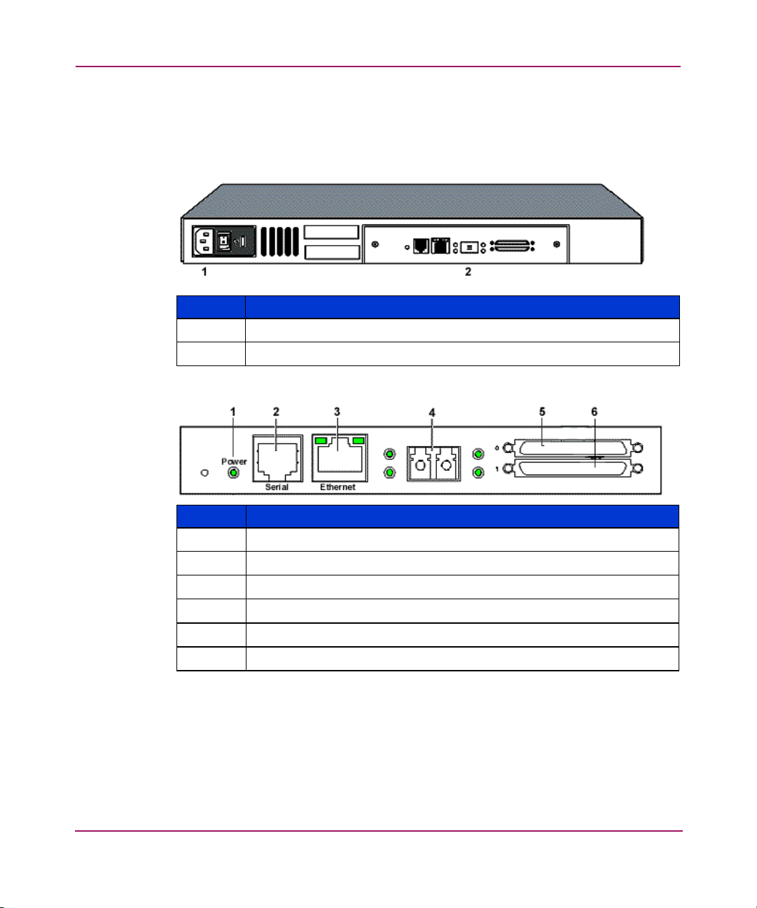
Figure 1 and Figure 2 illustrate the panel view of the router.
Figure 1: Router illustration
Item Description
1
2
Figure 2: Router I/O panel
Power connector
I/O panel
Item I/O Panel
1
2
3
4
5
6
18 Network Storage Router N1200 User Guide
Power LED
Serial port, 6 pin RJ-11, RS-232
10/100 TX Ethernet port
Fibre Channel port
LVD SCSI Port 0
LVD SCSI Port 1
Page 19

Power Indicator
The router has one power LED.
Power indicator LED definition:
Green - Power has been applied to this module
Yellow - Power-On-Self-Test (POST) in process or processor problems
Serial Port
The router is equipped with one serial port. See Figure 2 on page 18 for the
location of the serial port.
The serial port can be used to access the Serial/Telnet user interface, which is used
to locally manage and configure the router.
Table 2: Serial Port Configuration
Introduction
Ethernet Port
BAUD Rate
Data Bits
Stop Bit
Parity
Flow Control
Autobaud, 9600, 19200, 38400, 57600, 115200
8
1
None
XON/XOFF
One Ethernet port with an LED indicator is included in the router. See Figure 2 on
page 18 for the location of the Ethernet port.
Ethernet port LED definition:
Activity - Port activity
Link - Valid Ethernet link
19Network Storage Router N1200 User Guide
Page 20

Introduction
Fibre Channel Port
One Fibre Channel port with LED indicators is included in the router.
See Figure 2 on page 18 for the location of the Fibre Channel port.
Fibre Channel LED definition:
Green (ACT) - Fibre Channel port activity
Green (LINK) - Valid Fibre Channel link
SCSI Buses
Two SCSI buses with LED indicators are included in the router. See Figure 2 on
page 18 for the location of the SCSI buses.
SCSI bus LED definition:
Green - SCSI bus activity on corresponding port
20 Network Storage Router N1200 User Guide
Page 21
Functional Overview
The router translates the Fibre Channel Protocol (FCP) to and from the SCSI
Protocol. It transfers commands, data, and status information to and from Fibre
Channel controllers and SCSI devices.
Supported devices include:
■ Initiator Devices – Fibre Channel and SCSI hosts
■ Direct Access Devices – RAID Controllers, disk drives, JBODs
■ Sequential Access Devices – Tape drives
■ Changer Devices – Tape and Magneto-Optical Libraries
The router provides multiple Fibre Channel to SCSI I/O configurations. A sample
configuration is illustrated in Figure 3.
Figure 3: Example configuration
SCSI
Tape
Drives
SCSI
Tape
Libraries
Introduction
FC Host
Pwr.
EthernetSerial
Fibre Channel
SCSI
Fibre
Link/
Channel
Act
LVD/SE SCSl
0
1
StorageWorks
Router
SCSI
Tape
Libraries
SCSI
Tape
Drives
21Network Storage Router N1200 User Guide
Page 22
Introduction
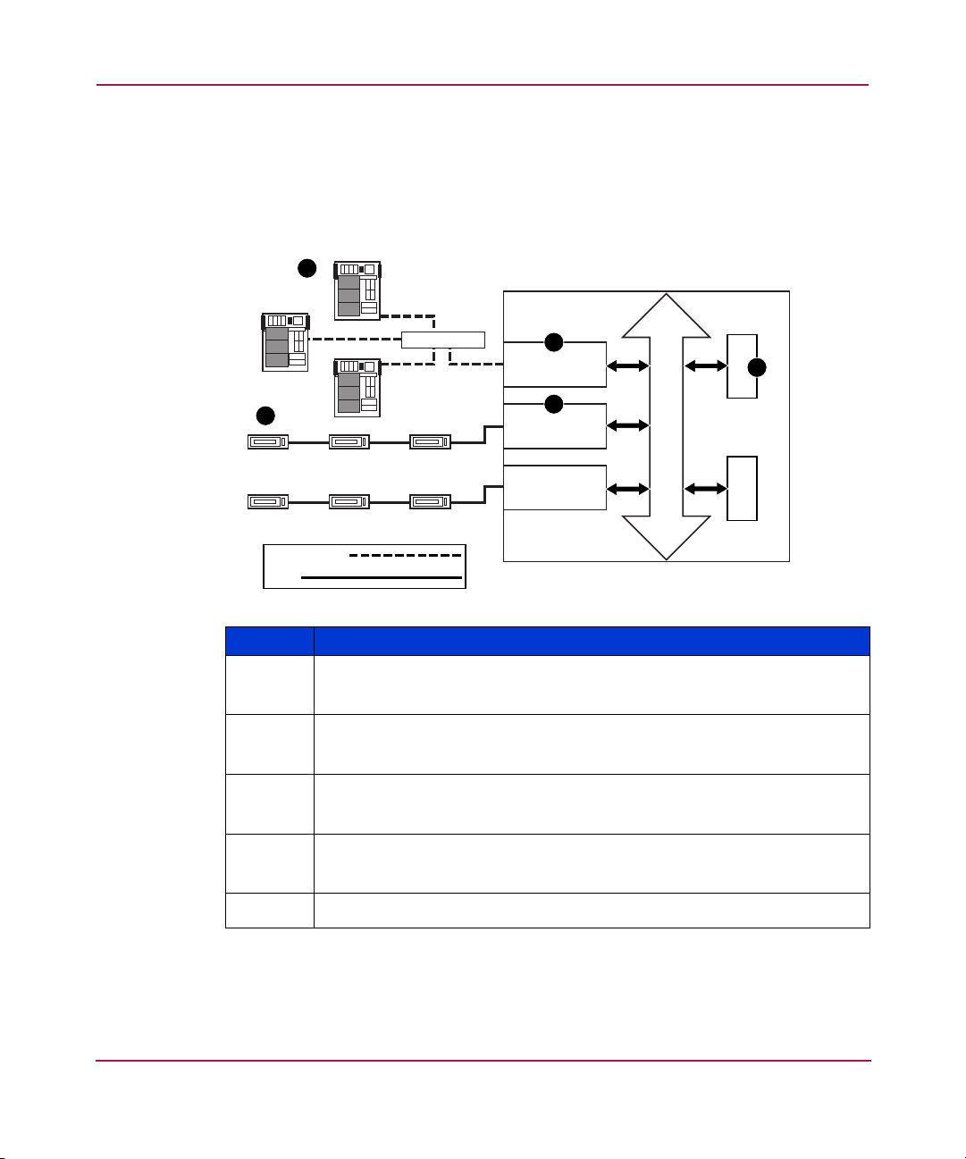
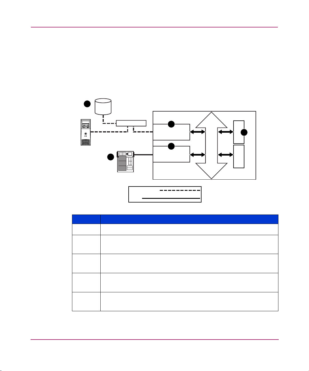
Fibre Channel to SCSI Protocol Process
This section describes the steps the router uses to convert Fibre Channel host
protocol to SCSI device protocol (see Figure 4).
Figure 4: Converting Fibre Channel to SCSI process
FC Host
1
FC Host
StorageWorks Router
5
SCSI DeviceSCSI Device
Fibre Channel
SCSI
FC Host
Hub or Switch
SCSI Device
SCSI DeviceSCSI DeviceSCSI Device
2
FC Controller
4
SCSI Controller
SCSI Controller
Bus
Table 3: Converting Fibre Channel to SCSI process description
Item Description
1
A Fibre Channel host issues an encapsulated FCP protocol command
packet to the router.
2
The router Fibre Channel controller interprets the Fibre Channel
information and places the packet in buffer memory.
3
The router interprets the Fibre Channel information packet and
programs the router SCSI controller to process the transaction.
4
The router SCSI controller sends the command to the SCSI device
(target).
5
The SCSI target interprets the command and executes it.
3
Memory Processor
22 Network Storage Router N1200 User Guide
Page 23
SCSI to Fibre Channel Protocol Process
In this example, a SCSI host (initiator) on the SCSI bus issues commands and the
information is passed through the router to a target on the Fibre Channel Storage
Area Network (FC-SAN). Figure 5 is an illustration of the process and defines
each step.
Figure 5: Converting SCSI to Fibre Channel protocol process
FC Device
5
Introduction
StorageWorks Router
FC Device
Hub or Switch
SCSI Host
1
Fibre Channel
SCSI
4
FC Controller
2
SCSI Controller
Bus
Memory Processor
Table 4: Converting SCSI to Fibre Channel protocol process description
Item Description
1
2
A SCSI host issues a command to the router.
The SCSI controller in the router interprets the command and places it in
buffer memory.
3
The router processor interprets data and programs the router Fibre
Channel controller to process the transaction.
4
The router Fibre Channel controller translates data into an FCP protocol
packet and sends it to the Fibre Channel target.
5
The Fibre Channel target interprets the FCP protocol packet and executes
the command.
3
23Network Storage Router N1200 User Guide
Page 24

Introduction
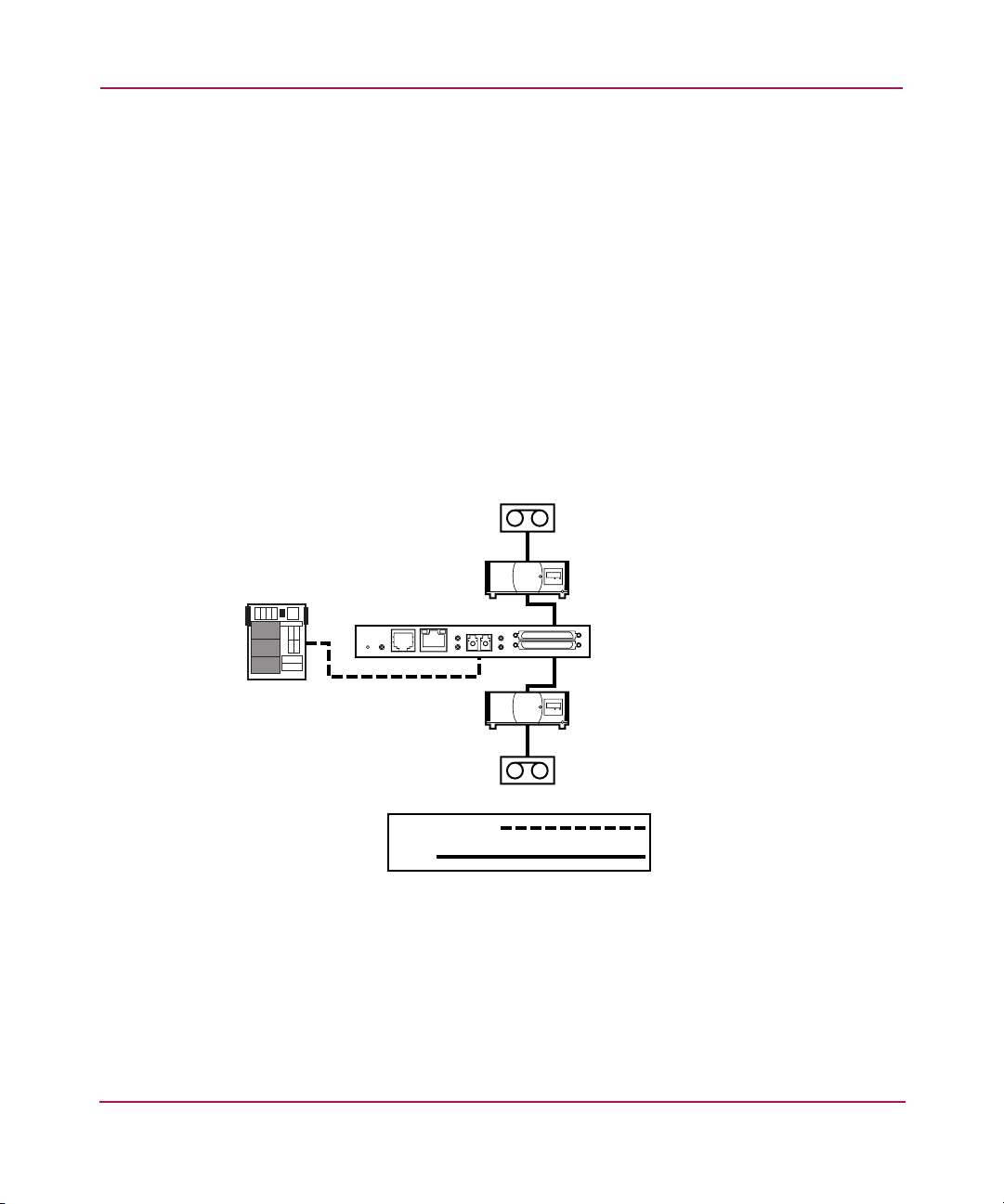
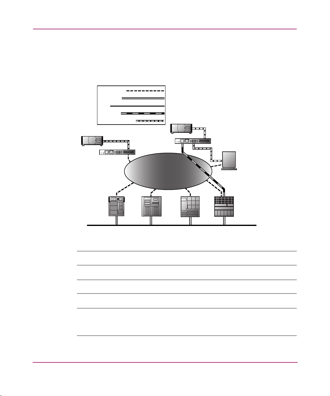
LAN-free Backup and Restore
The router can enable LAN-free backup/restore to allow the bulk of data traffic to
be moved from the LAN to the storage area network (SAN) (see Figure 6).
Figure 6: LAN-free backup and restore
SCSI TAPE
UNIT
Fibre
LVD/SE SCSl
Link/
Channel
Act
Pwr.
StorageWorks
Router
0
1
EthernetSerial
SCSI TAPE
UNIT
StorageWorks
Router
Link/
Channel
Act
Pwr.
EthernetSerial
SAN
Fibre Channel
ETHERNET
SCSI
DATA MOVEMENT
Fibre
LVD/SE SCSl
0
1
FIBRE CHANNEL
DISK
SERVER SERVER
SERVERSERVER
LAN
24 Network Storage Router N1200 User Guide
Page 25
Server-Free Data Movement
Used with server-free application software, Copy Manager allows the server to off
load data movement to the router and free up server resources (see Figure 7).
Figure 7: Server-free data movement
Fibre Channel
ETHERNET
SCSI
COMMAND
DATA MOVEMENT
SCSI TAPE
UNIT
Fibre
LVD/SE SCSl
Link/
Channel
Act
Pwr.
StorageWorks
Router
0
1
EthernetSerial
SCSI TAPE
UNIT
StorageWorks
Router
Pwr.
SAN
Introduction
Fibre
LVD/SE SCSl
Link/
Channel
Act
0
1
EthernetSerial
FIBRE CHANNEL
DISK
SERVER SERVER
SERVERSERVER
LAN
Note: The router implementation of Extended Copy does not support SDMP protocol.
Note: Copy Manager can perform simultaneous Extended Copy commands.
Note: Server-free backup can be activated using the Active Fabric Configuration Menu
option. When activated, the router is enabled for both server-free and LAN-free
capabilities. When deactivated, only LAN-free capabilities are supported.
25Network Storage Router N1200 User Guide
Page 26

Introduction
Note: The router implementation of the Extended Copy command is available to
application programmers. See Appendix B, “Controller LUN Commands” on page 161
for additional information.
Router Specifications
This section lists the environmental requirements of the router.
Operating Environmental Requirements
■ Temperature: 0 to 50°C
■ Relative Humidity: 5 to 80% (non-condensing)
Shipping and Storing Environmental Requirements
■ Temperature: -40 to +55°C
■ Relative Humidity: 0 to 92% (non-condensing)
Power Requirements
■ VAC: 100 - 240 (auto sensing)
■ 50/60 Hz, 2.0 Amps (each power supply)
26 Network Storage Router N1200 User Guide
Page 27

Configuration Overview
The HP StorageWorks Network Storage Router can be configured and managed
using several user interfaces (UI). Each UI is introduced in this chapter, along
with information about common configuration settings.
Included are:
■ Router Default Ethernet Settings, page 28
■ UI Overview, page 29
■ Common Configuration Settings, page 31
— Controller LUN Commands
— SCSI Bus Configuration
— Fibre Channel Port Configuration
— Fibre Channel Arbitrated Loop Configuration
— Fibre Channel Switched Fabric Configuration
—Discovery Mode
— Host Device Configuration
— Logical Unit Management
2
— Buffered Tape Writes
Note: Before attempting to configure the router, a basic understanding of Fibre Channel and
SCSI devices is recommended. For information on SCSI standards, refer to publications from the
X3T10 committee of ANSI (American National Standards Institute). For information on Fibre
Channel standards, refer to publications from the X3T11 committee of ANSI. For those who are
interested in purchasing approved American National Standards and Technical Reports, contact
ANSI at (212) 642-4900.
27Network Storage Router N1200 User Guide
Page 28

Configuration Overview
Router Default Ethernet Settings
Some of the basic factory default values are:
■ IP address: http://1.1.1.1/
■ Subnet mask: 255.255.255.0
■ Gateway address: 0.0.0.0
■ User name: root
■ Password: password
HP recommends that you change these values from the defaults.
All settings within the router configuration are preset with default values. These
values are set to allow the router to be installed into most HP environments with
little or no configuration changes.
After changing the basic default values listed above, carefully consider any
additional configuration changes.
After the initial configuration of the router is established, HP recommends
backing up the configuration to an external file. If needed, during a recovery
process, this file can then be restored back onto the router.
28 Network Storage Router N1200 User Guide
Page 29

UI Overview
The router supports the following user interfaces:
■ Visual Manager, page 29
■ Serial, page 29
■ Telnet, page 29
■ FTP, page 29
Visual Manager
Visual Manager lets you view and change router configuration from any standard
Web browser. Information is dynamically generated in an HTML format so that
any web browser can access it.
Unless the default values are used, the 10/100BaseT Ethernet port must be
configured using the serial port with an appropriate IP address, subnet mask, and
gateway prior to use.
For complete information on accessing and using Visual Manager, see “Visual
Manager User Interface” on page 37.
Configuration Overview
Serial
Telnet
FTP
The serial port allows for configuration of device characteristics from a terminal
or terminal emulator. Multiple serial connections cannot be run at the same time.
For complete information on accessing and using the Serial UI, see “Serial/Telnet
User Interface” on page 87.
From most Microsoft® Windows® 9x, Windows NT®, and Windows 2000®
systems, users can start a Telnet session from the DOS (command) shell after the
IP address has been set.
For complete information on accessing and using the Telnet UI, see “Serial/Telnet
User Interface” on page 87.
The router supports the use of the FTP UI to perform several copy procedures
using the
put and the get commands.
29Network Storage Router N1200 User Guide
Page 30

Configuration Overview
For more information, see “FTP User Interface” on page 143.
SNMP (SNMP is not supported)
SNMP is not supported
30 Network Storage Router N1200 User Guide
Page 31

Common Configuration Settings
To provide connectivity between hosts and devices, the router must establish an
address on each connected Fibre Channel network and SCSI bus. The following
paragraphs discuss configuration settings that are commonly modified and are
available in the Visual Manager UI and the Serial/Telnet UI. For procedural
information on accessing and changing these settings, see “Visual Manager User
Interface” on page 37 and “Serial/Telnet User Interface” on page 87.
Controller LUN Commands
The router supports a set of SCSI-3 commands that can be received as FCP
commands over the Fibre Channel port. These commands provide support for
value added features such as Extended Copy. When using these commands, they
must be sent to the Controller LUN. For more information, see Appendix B,
“Controller LUN Commands” on page 161.
SCSI Bus Configuration
The router can appear on a SCSI bus as a pair of initiators. The primary Initiator
ID can be set to any valid SCSI address (0-15) and is used for most traffic. The
alternate Initiator ID can also be set to any valid SCSI address (0-15) and is for
use with high priority traffic. The Initiator IDs (primary and alternate) should not
be set to the same SCSI address and no other devices on the SCSI bus may use
either of these SCSI addresses.
The router can also appear as one or more Target ID on a SCSI bus. By default, no
Target IDs are set up.
Configuration Overview
The router provides the capability to reset SCSI buses during the router boot
cycle. This allows devices on a SCSI bus to be in a known state. The reset option
can be enabled/disabled during configuration of the router. The SCSI bus reset
feature is enabled in the default configuration but should be disabled for
configurations using multiple initiators, tape changers or other devices that have
long reset cycles, or for environments that are adversely affected by bus resets.
The router negotiates the maximum values for transfer rates and bandwidth on a
SCSI bus. If an attached SCSI device does not allow the full rates, the router will
use the best rates it can negotiate for that device. Because negotiation is on a
device-specific basis, the router can support a mix of SCSI device types on the
same SCSI bus.
31Network Storage Router N1200 User Guide
Page 32

Configuration Overview
Fibre Channel Port Configuration
By default, the configuration of the Fibre Channel ports is set to N_Port, forcing
the router to configure as an Arbitrated Loop.
Note: By default, the Fibre Channel port speed is set to 1 Gbps. Changes to the Fibre Channel
port speed must be manually set, such as for 2 Gbps. If set incorrectly and the router is plugged
into a Loop or Fabric, the unit may receive framing errors because of the incorrect Fibre
Channel link speed.
Fibre Channel Arbitrated Loop Configuration
On a Fibre Channel Arbitrated Loop, each device appears as an Arbitrated Loop
Physical Address (AL_PA). To obtain an AL_PA, two methods can be used:
■ Soft Addressing
■ Hard Addressing
Soft addressing is the default setting.
Soft Addressing
During soft addressing, the router automatically acquires the first available loop
address, starting from 01 and moving up to EF. The router may participate on the
Fibre Channel loop as long as there is at least one address available on the loop
connected to the router. Fibre Channel supports up to 126 devices on an
Arbitrated Loop.
Hard Addressing
During hard addressing, the router attempts to acquire the AL_PA value specified
in the configuration settings. If the desired address is not available at loop
initialization time, the router negotiates the next available soft address. This
allows both the loop and the router to continue to operate.
Hard addressing is recommended for Fibre Channel Arbitrated Loop
environments where it is important that the Fibre Channel device addresses do not
change. Device address changes can affect the mapping represented by the host
operating system to the application, and have adverse effects. An example is tape
library installation, where the application configuration requires fixed device
identification for proper operation.
32 Network Storage Router N1200 User Guide
Page 33

Fibre Channel Switched Fabric Configuration
When connected to a Fibre Channel switch, the router is identified to the switch as
a unique device by the factory programmed World Wide Name (WWN).
Discovery Mode
This feature makes it easy to discover attached Fibre Channel and SCSI target
devices and automatically map them on the host side for the bus/port in question.
There are two discovery methods available:
■ Manual discovery
■ Auto discovery
Auto Discovery can be set to occur after reboot events (when the router reboots)
or link-up events (for instance, when cables are attached or a hub is rebooted).
Auto Discovery can be disabled by setting the router to Manual Discovery.
Host Device Configuration
A host system using a Fibre Channel Host Bus Adapter (HBA) will typically map
devices into the existing device-mapping scheme used by that operating system.
Refer to the HBA manual for the mapping table.
Mapping involves pairing FC_AL_PA to SCSI target address. The HBA will
claim enough SCSI bus entries to allow up to 125 Fibre Channel targets to be
mapped to SCSI Bus: Target entries. This is usually done by a fixed mapping of
AL_PA to Bus: Target. In such a configuration, the router corresponds to a
Bus: Target identifier, with the attached SCSI devices appearing as logical units
(LUNs). Operating systems can extend the available SCSI limit of 15 targets per
bus. Although this is not an issue for the operating system or most applications,
there are cases where older applications can have expectations about what
constitutes a valid SCSI ID, and thus may not correctly handle certain mappings.
In particular, some applications may exhibit difficulties addressing target IDs
greater than 15 (for example, 16 and up). This situation can be resolved by
configuring the router to use hard addressing and setting the AL_PA to a value
less then 16 that the HBA will be able to map.
Configuration Overview
For example, depending on the Fibre Channel HBA, if the hard AL_PA selection
is 1, then the address is 1. If the selection is 125, the AL_PA address is 0xEF.
Some Fibre Channel HBAs will map devices differently, so verify the AL_PA by
reviewing the documentation for the HBA.
33Network Storage Router N1200 User Guide
Page 34

Configuration Overview
Logical Unit Management
Because SAN resources can be shared, it is possible for multiple hosts to have
access to the same devices on the SAN. To prevent conflicts, the router provides
LUN management as a means to restrict device access to certain hosts. LUN
management goes beyond simple LUN masking, to prevent gaps in the list of
LUNs presented to a host.
LUN management maps can be created for different views of the devices attached
to the router. Each Fibre Channel host is assigned a specific map configuration.
Not only can the administrator control which devices a host may access, but also
which LUNs are used to access these devices.
For a Fibre Channel host, a map is a table of LUNs, where each entry is either
empty or contains device address information needed for host/device
communication.
For a SCSI host, a map contains a list of target IDs, each of which has its own
table of LUNs with address information needed for host/device communication.
Note: The router can respond to multiple Target IDs on a SCSI bus.
Both Fibre Channel ports and SCSI buses have user-defined maps and predefined
maps.
There are three predefined maps:
■ Indexed Maps
■ Auto Assigned Maps
■ SCC Maps
When a host sends a command, the router will select which map to use, based on
the port receiving the command and the ID of the host sending the command. For
Fibre Channel ports, the host ID is the World Wide Name; for SCSI buses, the
host ID is the Initiator ID (0 - 15). When a host is unknown or is not assigned a
specific map, the router will use the default map.
Indexed Maps
An indexed map is initially empty and can be modified by the user.
34 Network Storage Router N1200 User Guide
Page 35

Auto Assigned Maps
An auto assigned map is built dynamically and contains all of the devices found
during discovery. This map will change automatically any time the discovery
process finds a change in the devices attached. This map cannot be modified by
the user.
SCC Maps
An SCC map is only available on Fibre Channel ports and contains only a single
entry for LUN 0. This LUN is a router controller LUN. Access to attached devices
is managed using SCC logical unit addressing.
Buffered Tape Writes
This option is designed to enhance system performance by returning status on
consecutive write commands prior to the tape device receiving data. If data does
not transfer correctly, the router returns a check condition on a subsequent
command.
Commands other than Write are not issued until status is received for any
pending write, and status is not returned until the device completes the command.
This sequence is appropriate for tasks such as file backup or restore.
Configuration Overview
Some applications require confirmation of individual blocks being written to the
medium, such as for audit trail tapes or log tapes. In these instances, the Buffer
Tape Writes option must be disabled.
35Network Storage Router N1200 User Guide
Page 36

Configuration Overview
36 Network Storage Router N1200 User Guide
Page 37

Visual Manager User Interface
The HP StorageWorks Visual Manager user interface (UI) provides a graphical
format that is used to remotely view and change router configurations. Use the
Microsoft Internet Explorer or Netscape (version 6.2 or greater) web browsers to
access Visual Manager.
Information is presented in HTML format in accordance with the W3C
specification for HTML 3.2. Current W3C recommendations and other technical
documents can be found at
This chapter describes the menus and tasks of the Visual Manager UI and is
organized using the same structure of the Visual Manager UI:
■ Visual Manager Access, page 39
■ Visual Manager Best Practices, page 41
■ Main Menu, page 42
■ System Menu, page 45
— Serial Configuration
— Network Configuration
— SNMP Configuration (not supported)
www.w3 .org/TR/
3
.
— Active Fabric Configuration
— User Configuration
— Real-Time Clock Configuration
— Reset Menu
■ Ports Menu, page 54
— Fibre Channel Port Configuration
— SCSI Bus Configuration
■ Discovery Menu, page 63
■ Mapping Menu, page 64
37Network Storage Router N1200 User Guide
Page 38

Visual Manager User Interface
— Common Fibre Channel and SCSI Mapping Tasks
— SCSI Mapping Tasks
■ Statistics Menu, page 73
■ Utilities Menu, page 74
— FTP Utility Access
— Trace Settings Configuration
— Current, Previous, and Last Assert Trace Displays
— Clear Current Traces and Clear Assert Traces
— Event Log Configuration
— Event Log Display
— Clear Event Log
■ Report Menu, page 84
■ Reboot Option, page 85
38 Network Storage Router N1200 User Guide
Page 39

Visual Manager Access
Visual Manager (VM) can be accessed from any standard web browser:
1. Connect a 10/100BaseT Ethernet cable to the back of the router.
2. Apply power to the connected SCSI and/or Fibre Channel devices.
Wait for all of the devices to complete their power-up routines.
3. Apply power to the router.
4. Apply power to the host computer.
5. Enter the router IP address in the address field of the Web browser of the host
computer.
Note: To access VM, the router must be assigned a valid IP address. The factory default setting
for the IP address allows access on a local area network only. If the factory default for the IP
address is already used by another device on the local network, the IP address must be
changed.
The factory default for the IP address is http://1.1.1.1/
Visual Manager User Interface
Note: If the IP address of the router is not known or needs to be changed, connect to the router
using a serial connection. The current router IP address is displayed and can be changed in the
serial Ethernet Configuration Menu.
The Visual Manager home page is displayed, showing router status
information. The home page is accessible to anyone who knows the router IP
address.
6. Select the desired menu option to access menus and screens.
The Password dialog box is displayed.
39Network Storage Router N1200 User Guide
Page 40

Visual Manager User Interface
7. Enter the authorized user name and password (see Figure 8).
Figure 8: Password dialog box
The default user name is root and the default password is password. This
information is required only once per session.
Note: HP recommends changing the user name and password from the defaults.
Note: Username and password are case-sensitive.
Full access is granted to the VM menus.
Note: To end the current session of VM, the browser window must be closed.
Navigating the browser to another URL does not end the current session.
40 Network Storage Router N1200 User Guide
Page 41

Visual Manager Best Practices
The following recommendations should be observed:
■ A standard keyboard and mouse must be used to navigate in the VM.
■ The router is shipped with a configuration of default settings that is acceptable
for most system environments. Few changes to the configuration should be
necessary.
■ After any configuration changes are made, depending on the menu option,
select Submit or Configure to send changes from the Web browser to the
router.
■ Changes will take effect during the next router reboot cycle.
■ If the configuration has been modified to meet company-specific needs, back
up the company-specific configuration to an external file. If necessary, these
settings can later be restored to the router.
■ Except for the user name, password, and override settings, fields are not
case sensitive.
■ HP recommends that you not bookmark VM pages with the Web browser.
■ Because configuration information is transmitted via URLs, it is possible that
the router could be configured with information present at the time a page was
bookmarked.
■ HP recommends navigating using only the Web page links contained in VM
itself.
Visual Manager User Interface
■ Depending on the Web browser used, these links will often appear as
highlighted text. By selecting these links, VM can be safely navigated.
41Network Storage Router N1200 User Guide
Page 42

Visual Manager User Interface
Main Menu
The Main Menu home page is displayed whenever VM is accessed.
The home page contains status information, including a physical image of the
router (see Figure 9).
Figure 9: Visual Manager Home page
Home page information includes:
■ The HP logo is located in the upper left corner of the page. Figure 10 is an
example of this portion of the home page screen. If the Internet is accessible
to the host, click the HP logo to open the HP website.
Figure 10: HP logo
42 Network Storage Router N1200 User Guide
Page 43

Visual Manager User Interface
■ An illustration of the router is located near the top of the home page.
Figure 11 is an example of this portion of the home page screen.
Figure 11: VM router image
■ The router image is interactive, allowing quick access to configuration menus:
— To display current settings and status for a port, click the corresponding
port shown in the router image.
— To open a menu for making changes to the configuration for that
particular port or bus, click the desired Fibre Channel port or SCSI bus.
— To open the Network Configuration Menu, click the Ethernet port.
■ Router status information is located in the body of the home page and
includes:
— Platform information
— Temperature measurements
The home page monitors the temperature of the router, checking once
every 60 seconds. If the detected temperature is outside the operating
range, a pop-up notification message indicates that the unit is about to
shut down.
— Voltage measurements
Note: The temperature warning message appears only on the home page.
43Network Storage Router N1200 User Guide
Page 44

Visual Manager User Interface
■ The Main Menu option bar is located at the left-side of the home page. Use
this option bar to access the configuration menus (see Figure 12).
Figure 12: Main Menu option Bar
■ Main Menu options:
— Home displays router status information.
— System configures standard system components.
— Ports configures the Fibre Channel port and SCSI buses.
— Discovery displays devices and discovers new devices.
— Mapping displays and configures maps.
— Statistics displays router statistics.
— Utilities configures utility settings.
— Report displays system information.
— Reboot restarts the router.
Each Main Menu option is discussed in the following sections of this chapter.
44 Network Storage Router N1200 User Guide
Page 45

System Menu
The System Menu is accessed from the Main Menu and is used to view and
configure serial, network, Trap, Active Fabric, clock, and power supply
components (see Figure 13).
Figure 13: System page
Visual Manager User Interface
System page tasks:
■ Serial configuration configures the baud rate.
■ Network configuration configures Ethernet settings.
■ Active Fabric configuration configures Active Fabric settings.
■ User configuration configures user security settings.
■ Real-Time Clock configuration configures system date and time.
■ Power Supply configuration configures the number of power supplies.
■ Reset menu restores factory default settings.
Each menu option is discussed in the following paragraphs.
45Network Storage Router N1200 User Guide
Page 46

Visual Manager User Interface
Serial Configuration
The Serial screen is used to change the baud rate for the serial port
(see Figure 14).
If the Autobaud feature is being used, it may not be necessary to set the baud rate.
Figure 14: Serial screen
The current baud-rate setting is displayed.
HP recommends setting the baud rate to 115200.
46 Network Storage Router N1200 User Guide
Page 47

Network Configuration
The Network screen is used to enter network settings, including Ethernet settings
(see Figure 15).
Figure 15: Network screen
Visual Manager User Interface
Network Menu options:
■ Network Settings changes the hostname.
■ Port Configuration changes Ethernet configuration settings.
Each of these Network Menu options is discussed in the following sections.
Network Settings
To change the hostname, enter an alphanumeric entry of one word up to 8
characters in length. Then, select Submit.
47Network Storage Router N1200 User Guide
Page 48

Visual Manager User Interface
Port Configuration (Ethernet Settings) (Service Mode - Restricted Access)
To change the Ethernet configuration settings, select the Ethernet port icon.
The Ethernet Configuration dialog box is displayed (see Figure 16).
Figure 16: Ethernet Configuration dialog box
Ethernet configuration settings:
■ Ethernet Mode can be set to one of the following options:
—10Mps Only
— 100Mps (half duplex) Only
— 100Mps (full duplex) Only
— 10/100Mps (Auto-Neg.)
■ MAC address is the Ethernet physical address of the router.
Caution: If this configuration setting is incorrectly set, processing difficulties may
occur. Before changing this setting, evaluate the need for the change and verify the
desired setting. HP recommends backing up the router configuration to an external file
before making changes to this setting.
The Ethernet physical address is always assigned by the manufacturer.
■ IP address (default: 1.1.1.1) is the IP address of the router.
■ Subnet Mask (default: 255.255.255.0) is the IP subnet mask for the router.
■ IP Gateway (default: 0.0.0.0) is the IP address of the gateway for the Ethernet
network connected to the router.
■ DHCP enables or disables support for Dynamic Host Configuration Protocol
(DHCP).
48 Network Storage Router N1200 User Guide
Page 49

Visual Manager User Interface
When DHCP is enabled, the router requests a dynamic IP address from a
DHCP server on the Ethernet network. The router must be rebooted before an
IP address will be requested from the DHCP server. After the router is
rebooted, the HTTP session must be restarted. The IP address will be different
from the former non-DHCP IP address.
Note: To use the DHCP feature, a DHCP server must be operational on the Ethernet
network. If the DHCP feature is used when there is not DHCP server, the standard for
DHCP requires the router wait thee minutes for a response from a DHCP server before
timing out.
Some DHCP servers allow a lease reservation to be set up for an IP address by
providing the server with the Ethernet MAC address. The DHCP server
always provides the same IP address to the router. This setup can be useful for
remote management of the router via Telnet or VM. Because the method of
setting up a lease reservation varies, depending on the DHCP server being
used contact the Network Administrator for assistance.
49Network Storage Router N1200 User Guide
Page 50

Visual Manager User Interface
Active Fabric Configuration
The Active Fabric screen allows setup of Active Fabric options (see Figure 17).
Figure 17: Active Fabric screen
Active Fabric settings:
■ Server-Free Backup Mode toggles between Enabled and Disabled.
When enabled, server-free backup capability is enabled to allow Extended
Copy commands.
■ Number of Controller LUNs (default: 1) sets the number of controller LUNs
reported by the router.
The number must be in the range of 0 through 4.
Note: For Server-Free Backup Mode functionality, if addressing a controller LUN is
desired, at least one controller LUN must be enabled and included in a relevant map.
Note: If Server-Free Backup Mode is enabled, Fibre Channel Discovery must be
enabled to allow router access to Fibre Channel targets.
50 Network Storage Router N1200 User Guide
Page 51

For information on controller LUN and Extended Copy commands, see Appendix
B, “Controller LUN Commands.”
For general information about server-free backups, see Chapter 1, “Introduction.”
User Configuration
The User screen is used to set up router security (see Figure 18).
Figure 18: User screen
Visual Manager User Interface
User settings:
■ User Name (default: root) is any alphanumeric combination.
■ Password (default: password) is any alphanumeric combination.
The user name and password should be unique and kept confidential. HP
recommends using a combination of letters and numbers when creating the user
name and password.
Note: These security settings affect all user interfaces of the router.
51Network Storage Router N1200 User Guide
Page 52

Visual Manager User Interface
Real-Time Clock Configuration
The Real Time Clock screen is used to set the system time and date
(see Figure 19).
Figure 19: Real-Time Clock screen
Real-Time Clock settings:
■ Date Settings sets the month, date, and year.
— Use a four-digit number to represent the year.
■ Day of Week sets the day of week.
■ Time Settings sets the hours, minutes, and seconds.
— The system clock is a 24-hour clock.
52 Network Storage Router N1200 User Guide
Page 53

Reset Menu
Visual Manager User Interface
The Reset Menu is used to reset the router to factory default settings
(see Figure 20).
Figure 20: Reset to Factory Default screen
Current router activities are disrupted while the unit resets the configuration to the
factory defaults and saves those options to FLASH memory.
Caution: Resetting the router configuration to the factory defaults will delete
custom maps or map changes.
Note: Resetting to factory defaults through VM will not affect Ethernet connectivity.
User-configured values for the IP address and gateway will be retained.
53Network Storage Router N1200 User Guide
Page 54

Visual Manager User Interface
Ports Menu
Accessed from the Main Menu, the Ports Menu is used to view and modify
configuration settings of the Fibre Channel port and SCSI buses (see Figure 21).
Figure 21: Ports Menu
The initial screen display of the Ports Menu includes summary information about
each Fibre Channel port and SCSI bus in the router.
Note: To view or change configuration settings of a specific port or bus, select it from
the menu bar on the left side of the screen or select the port or bus from the router
image at the top of the screen.
To make changes, modify the setting and then click Submit.
54 Network Storage Router N1200 User Guide
Page 55

Ports Menu tasks:
■ Fibre Channel Port configuration changes Fibre Channel port settings.
■ SCSI Bus configuration changes SCSI bus settings.
Each Ports Menu option is discussed in the following subsections.
Fibre Channel Port Configuration
When the Fibre Channel port is selected in Ports Menu, the Fibre Channel
Configuration screen is displayed (see Figure 22).
Figure 22: Fibre Channel Configuration screen
Visual Manager User Interface
Fibre Channel port settings:
■ Link Status indicates the port link status.
■ Port Name High sets a new value for the World Wide Port Name High.
Caution: If this configuration setting is incorrectly set, processing difficulties
may occur. Before changing this setting, evaluate the need for the change and
verify the desired setting. HP recommends backing up the router configuration
to an external file before making changes to this setting.
■ Port Name Low sets a new value for the World Wide Port Name High.
55Network Storage Router N1200 User Guide
Page 56

Visual Manager User Interface
■ Port Mode (default: N_Port) sets the port mode.
Port Mode settings:
— Auto Sense: In this mode, the Fibre Channel port tries to negotiate as a
— N_Port: (default) This mode allows the router to bypass the loop
■ Use Hard AL_PA enables or disables Hard AL_PA usage.
■ Hard AL_PA Settings displays the AL_PA Lookup Table.
Use the table to find the node number. This unique one-byte valid value
(derived from an Arbitrated Loop Topology defined in ANSI specification
FC_AL version 4.5) is used for the Fibre Channel configuration
(see Figure 23).
Figure 23: AL_PA lookup table
Caution: If this configuration setting is incorrectly set, processing difficulties
may occur. Before changing this setting, evaluate the need for the change and
verify the desired setting. HP recommends backing up the router configuration
to an external file before making changes to this setting.
loop. If it is not successful, then the Fibre Channel port negotiates as a
fabric. If the port comes up as a loop, it then determines whether it is on a
private or public loop.
negotiation and come up as a fabric only. If the router is on a loop, and
N_Port mode is selected, an error in communication may occur.
56 Network Storage Router N1200 User Guide
Page 57

Visual Manager User Interface
■ Discovery Mode (default: manual discovery on reboot events) determines
how the router will discover new Fibre Channel devices.
Discovery mode settings:
— Auto Discovery on Reboot Events allows the router to automatically
discover all Fibre Channel devices when rebooted or when link-up events
occur, such as connecting cables or rebooting network hubs.
— Both the ports and the devices behind the ports are discovered on all
subsequent link-up events.
— Auto Discovery on Link Up Events allows the router to automatically
discover all Fibre Channel devices when rebooted or when link-up events
occur, such as connecting cables or rebooting network hubs.
— Both the ports and the devices behind the ports are discovered for the first
link-up event. Subsequent link-up events will only discover the ports and
not the devices behind the ports.
— Manual Discovery Only (default) sets discovery of new devices to occur
only after the user selects the Discovery option from the Main Menu or
when a Registered State Change Notification (RSCN) is received from a
fabric.
Note: SCSI devices attached to a Fibre Channel must be mapped as sequential Fibre
Channel LUNs starting at LUN number 00. Skipping LUN numbers is not recommended
when mapping Fibre Channel LUNs because Fibre Channel Discovery stops the
discovery process whenever an empty LUN position is found.
■ Buffered Tape Writes (default: enabled) enables or disables the Buffered
Tape Writes option.
Caution: If this configuration setting is incorrectly set, processing difficulties
may occur. Before changing this setting, evaluate the need for the change and
verify the desired setting. HP recommends backing up the router configuration
to an external file before making changes to this setting.
When enabled, to enhance performance, Buffered Tape Writes return status
on consecutive write commands prior to the tape device receiving data.
57Network Storage Router N1200 User Guide
Page 58

Visual Manager User Interface
■ Buffered Tape Queue Depth sets the Buffered Tape Queue Depth.
Select a setting of 0 through 10 from the drop-down list.
■ Default Map (default: indexed) sets the current mapping mode for the
selected port.
The current map can be set to:
— Indexed (default)
— Auto-assigned contains all the SCSI devices that are attached to the
—SCC
For more information about mapping modes, see Appendix C, “Addressing
Methods and Table Structures” on page 169.
For information on changing map settings, see “Mapping Menu” on page 64.
■ Performance Mode (default: 2 Gbps) toggles between 1 Gbps and 2 Gbps.
Note: If set incorrectly and the router is plugged into a Loop or Fabric, the unit may
receive Framing errors due to the incorrect Fibre Channel link speed.
router.
■ Override Settings (service mode-restricted access) enhances interoperability
with some storage devices that require special consideration during setup of
the router configuration menus.
— Hi-Sup Bit toggles between Set and Clear.
— Force FCP Response Code toggles between Off and On for support of
HP-specific HBA #223180-B21 and #120186-001.
— Initiator Bit toggles between Set and Clear.
— When using the router in a router-to-router configuration, this option
should be configured to Set. A router-to-router configuration is a type of
configuration where one router appears as a target to another initiator
router.
— Link Garbage Deletion toggles between Enabled and Disabled.
58 Network Storage Router N1200 User Guide
Page 59

SCSI Bus Configuration
When a SCSI bus is selected in the Ports Menu, the SCSI Bus Configuration
screen is displayed (see Figure 24).
Figure 24: SCSI Bus Configuration screen
SCSI bus configuration settings:
Visual Manager User Interface
■ Primary Initiator ID (default: 7) must be a unique ID.
■ Alternate Initiator ID (service mode-restricted access) (default: none) will
be used if the primary ID is taken. Must be a unique ID.
■ Target ID(s) adds or removes Target IDs.
Caution: If this configuration setting is incorrectly set, processing difficulties
may occur. Before changing this setting, evaluate the need for the change and
verify the desired setting. HP recommends backing up the router configuration
to an external file before making changes to this setting.
Note: Target IDs must be setup prior to mapping devices on the SCSI bus.
59Network Storage Router N1200 User Guide
Page 60

Visual Manager User Interface
Note: Do not enable Target IDs unless there is a SCSI initiator on the bus that wants to
use Fibre Channel devices. This type of configuration is known as a Target Mode
configuration.
■ Discovery toggles between Enabled and Disabled.
■ Discovery Delay is the wait time after a power-up or reboot before
discovering SCSI devices.
Note: HP recommends setting the value to at least 2 seconds to ensure all SCSI devices
complete their individual power-ups.
■ Bus Reset on Boot toggles between Enabled and Disabled.
When enabled, the router will automatically reset SCSI buses during a power
up or reboot of the router.
Internal Termination toggles between Enabled and Disabled.
Caution: If this configuration setting is incorrectly set, processing difficulties
may occur. Before changing this setting, evaluate the need for the change and
verify the desired setting. HP recommends backing up the router configuration
to an external file before making changes to this setting.
When enabled, internal termination of the selected SCSI bus is allowed. When
disabled, the SCSI Bus, not the router handles SCSI termination.
■ Buffered Tape Writes (default: Enabled) toggles between Enabled and
Disabled.
When enabled, Buffered Tape Writes enhance system performance. Buffered
Tape Writes return status on consecutive write commands prior to the tape
device receiving data.
■ Default Map (default: auto-assigned) sets the current mapping mode for the
selected bus.
60 Network Storage Router N1200 User Guide
Page 61

Visual Manager User Interface
Caution: If this configuration setting is incorrectly set, processing difficulties
may occur. Before changing this setting, evaluate the need for the change and
verify the desired setting. HP recommends backing up the router configuration
to an external file before making changes to this setting.
The current map can be set to:
—Indexed
— Auto-assigned (default) contains all the devices attached to the router.
—SCC
For more information about mapping modes, see Appendix C, “Addressing
Methods and Table Structures” on page 169.
For information on changing map entries, see “Mapping Menu” on page 64.
■ Override Settings (service mode-restricted access) To override the settings of
a SCSI target, select a Target ID icon with the appropriate Target ID number.
After a specific Target is selected, the SCSI Override sub-screen is displayed
and is used to enter the Override settings (see Figure 25).
Figure 25: SCSI Device Override screen
SCSI bus override settings:
— CDB Length Override enables or disables the override of default CDB
lengths.
— CDB Group 6 Length Default (default: 0) can be set to 0, 6, 10, or 12.
— CDB Group 7 Length Default (default: 0) can be set to 0, 6, 10, or 12.
— Wide Negotiation enables or disables negotiation on a wide SCSI bus.
61Network Storage Router N1200 User Guide
Page 62

Visual Manager User Interface
— Synchronous Negotiation enables or disables synchronous negotiation
— Synchronous Parameter Override enables or disables parameters for
— Synchronous Period (default: 40) sets the maximum number of seconds
— Synchronous Offset (default: 16) sets the maximum variation in transfer
— Ultra SCSI-3 Negotiation enables or disables Ultra SCSI-3 support for
— When enabled, Ultra SCSI-3 Negotiation helps solve certain
on the SCSI bus.
synchronous negotiation.
allowed for negotiation.
rate that can be negotiated in megabytes per seconds (MB/s).
the selected Target ID.
compatibility issues in mixed vendor environments where there may be a
device that cannot handle automatic negotiation of the bus speed or where
there is a device that negotiates to use Ultra SCSI-3 but cannot handle the
speed.
62 Network Storage Router N1200 User Guide
Page 63

Discovery Menu
Accessed from the Main Menu, the Discovery Menu is used to view Target
devices and discover new Target devices (see Figure 26).
Figure 26: Discovery page
Visual Manager User Interface
To perform a manual discovery:
1. Select the Fibre Channel port or SCSI bus from the menu bar or the router
image.
2. Then, select Go.
63Network Storage Router N1200 User Guide
Page 64

Visual Manager User Interface
Mapping Menu
Each physical port/bus on the router can have the following maps:
Table 5: Device Map Types
Map Type System/User Generated Fibre Channel or SCSI
Auto Assigned System Fibre Channel and SCSI
Indexed (default) System Fibre Channel and SCSI
SCC System SCSI
Custom User Fibre Channel and SCSI
Each map has a unique name and map ID; one of the maps must be identified as
the “current” map for the router to use.
Accessed from the Main Menu, the Mapping Menu is used to view and modify
host and map information for a Fibre Channel port or SCSI bus. Maps and hosts
can be added, edited, or deleted.
To view or change map settings of a specific port or bus:
1. Select the port or bus from the menu bar on the left side of the screen or from
the router image at the top of the screen.
2. Specific mapping information is displayed, including the name of the port, the
selected host, and the assigned map.
3. To make changes to the configuration, enter the new value and then select
Submit.
Because some mapping configuration settings are the same for Fibre Channel and
SCSI maps and some settings are unique, this mapping section is subdivided as
follows:
■ Common Fibre Channel and SCSI Mapping Tasks, page 65
■ Fibre Channel Mapping Tasks, page 66
■ SCSI Mapping Tasks, page 70
64 Network Storage Router N1200 User Guide
Page 65

Common Fibre Channel and SCSI Mapping Tasks
Although the initial screen display for Fibre Channel and SCSI maps differs
slightly, the available actions are the same (see Figure 27).
Figure 27: Initial Mapping screen
Visual Manager User Interface
Mapping screen options:
■ Add Host adds a new host.
To add an undefined host, type the hostname in the Add Host field and then
click Add.
■ Select Host adds a known host.
To select a previously set up host, expand the Select Host drop-down box and
select the host from the list.
■ Edit/View Host displays or changes host information.
Viewing and changing Host information is discussed in the following
paragraphs.
■ Delete Host deletes the current host.
Note: Built at runtime hosts cannot be deleted.
■ Add Map adds a new map.
65Network Storage Router N1200 User Guide
Page 66

Visual Manager User Interface
To add an undefined map, type the name of the map in the Add Map field and
then click Add.
■ Select Map adds a known map.
To select a previously set up map, expand the Select Map drop-down box and
select the map from this list.
■ Edit/View Map displays or changes map information.
Viewing and changing Map information is discussed in the following
paragraphs.
■ Delete Map deletes the current map.
Note: ”Indexed,” “Auto Assigned,” and “SCC” maps cannot be deleted or renamed.
■ Clone Map makes a copy of the current map.
Cloning makes it easier to setup new maps with similar information to
previously created maps. The new map must have a unique map ID and name.
Note: SCC and Auto-Assigned maps cannot be cloned.
Fibre Channel Mapping Tasks
Configuration tasks for Fibre Channel mapping includes:
■ Viewing and changing Fibre Channel host information
■ Viewing and changing Fibre Channel map information
Each task is discussed in the following paragraphs.
Viewing and Changing Fibre Channel Host Information
To view or change current host information:
1. In the Mapping Menu screen, select the desired Fibre Channel port.
2. Click Edit/View in the Host section of the screen.
The Fibre Channel Host Name dialog box is displayed. Current host
information is shown at the top of the dialog box.
66 Network Storage Router N1200 User Guide
Page 67

Visual Manager User Interface
3. Enter the new settings and then select Modify (see Figure 28).
Figure 28: Fibre Channel Host Name dialog box
Fibre Channel Host Name settings:
■ Host Name
■ Host ID (hexadecimal)
■ Port WWN Hi (hexadecimal) (service mode-restricted access)
■ Port WWN Lo (hexadecimal) (service mode-restricted access)
■ Node WWN Hi (hexadecimal) (service mode-restricted access)
■ Node WWN Lo (hexadecimal) (service mode-restricted access)
■ Map Name
67Network Storage Router N1200 User Guide
Page 68

Visual Manager User Interface
Viewing and Changing Fibre Channel Map Information
To view or change current Fibre Channel map host information:
1. In the Mapping Menu screen, select the Fibre Channel port.
2. Select Edit/View in the Map section of the screen.
The Fibre Channel Map dialog box is displayed. Current map information is
shown at the top of the dialog box.
3. Enter the new settings and then select the appropriate action button
(see Figure 29).
Figure 29: Fibre Channel Map dialog box
Note: Auto-Assigned and SCC maps cannot be modified, cleared, filled, or have
entries removed.
Note: Map settings are saved to memory when any button within the page is selected.
68 Network Storage Router N1200 User Guide
Page 69

Visual Manager User Interface
Fibre Channel map settings:
■ Clear Map clears all entries from the current map.
■ Remove Gaps removes any incremental gaps in the sequence of LUN listed
in the table.
When the system removes gaps from the table, the LUN are renumbered in
sequential order, starting with LUN 0.
Note: Some operating systems require gaps be removed in the mapping table in order
to detect all devices.
■ Fill Map fills in the current map.
To use the Fill Map option, expand the Fill Map Priority drop-down box,
select the fill option, and then click Fill Map.
When the map is filled, the display shows the current devices.
■ Delete deletes map entries.
To delete map entries, expand the Delete Map Item LUN drop-down box,
select the LUN, and then click Delete.
To delete a range of LUNs, select the beginning LUN to delete from the
“from” drop-down box and select the last LUN to delete from the “to”
drop-down box.
■ Discovered Device Entry adds a discovered device to the map.
To add a discovered device to the map, use the drop-down boxes to enter the
settings, and then click Create Entry in the Discovered Device Entry section
of the screen.
■ Manual Device Entry creates a map entry for a device that is not yet
discovered or installed.
To add a new device to the map, use the drop-down boxes to enter the settings,
and then click Create Entry in the Manual Device Entry section of the
screen.
69Network Storage Router N1200 User Guide
Page 70

Visual Manager User Interface
SCSI Mapping Tasks
Configuration tasks for SCSI mapping include:
■ Viewing and Changing SCSI Host Information
■ Viewing and Changing SCSI Map Information
Each task is discussed in the following paragraphs.
Viewing and Changing SCSI Host Information
To view or change current SCSI host information:
1. In the Mapping Menu screen, select the desired SCSI bus.
2. Click Edit/View in the Host section of the screen.
The SCSI Host Name dialog box is displayed. Current host information is
shown at the top of the dialog box.
3. Enter the new settings and then click Modify (see Figure 30).
Figure 30: SCSI Host Name dialog box
SCSI Host Name settings:
■ Host Name
■ Initiator ID
■ Map Name
70 Network Storage Router N1200 User Guide
Page 71

Viewing and Changing SCSI Map Information
To view or change current SCSI map host information:
1. In the Mapping Menu screen, select the desired SCSI bus.
2. Select Edit/View in the Map section of the screen.
The SCSI Map dialog box is displayed. Current map information is shown at
the top of the dialog box.
3. Enter the new settings and then click the appropriate action button
(see Figure 31).
Figure 31: SCSI Map dialog box
Visual Manager User Interface
Note: To map Fibre Channel devices to any SCSI initiator on the selected bus, a Target
ID must be enabled from the SCSI Bus Configuration Menu. A Target ID should only be
added if there is a SCSI initiator that needs to address Fibre Channel devices. Each
Target ID can be used to store up to 32 Fibre Channel devices.
Note: Auto-Assigned and SCC maps cannot be modified, cleared, filled, or have
entries deleted.
Note: Map settings are saved to memory when any button within the page is selected.
71Network Storage Router N1200 User Guide
Page 72

Visual Manager User Interface
Note: SCSI maps can be filled or devices can be added to them only when at least one
SCSI Target ID has been enabled in the SCSI Bus Configuration Menu.
SCSI Map settings:
■ Clear Map clears all entries from the current map.
■ Fill Map fills in the current map.
When the map is filled, the display shows the current devices.
■ Remove Gaps removes any incremental gaps in the sequence of LUN listed
in the table.
When the system removes gaps from the table, the LUN are renumbered in
sequential order, starting with LUN 0.
Note: Some operating systems require gaps be removed in the mapping table to detect
all devices.
■ Delete deletes map entries.
To delete a range of LUNs, select the beginning LUN to delete from the
“from” drop-down box and select the last LUN to delete from the “to”
drop-down box.
■ Discovered Device Entry adds a discovered device to the map.
To add a discovered device to the map, use the drop-down boxes to enter the
settings, and then click Create Entry in the Discovered Device Entry section
of the screen.
■ Manual Device Entry creates a map entry for a device that is not yet
discovered or installed.
To add a new device to the map, use the drop-down boxes to enter the settings,
and then click Create Entry in the Manual Device Entry section of the
screen.
72 Network Storage Router N1200 User Guide
Page 73

Statistics Menu
Accessed from the Main Menu, the Statistics Menu is used to display Fibre
Channel port and SCSI bus information (see Figure 32).
Figure 32: Statistics Menu
Visual Manager User Interface
To view information for a specific port or bus, click the component on the menu
bar or the router image. To refresh the display, select Reset SCSI system
statistics.
73Network Storage Router N1200 User Guide
Page 74

Visual Manager User Interface
Utilities Menu
Accessed from the Main Menu, the Utilities Menu is used to view and configure
utility options (see Figure 33).
Figure 33: Utilities Menu
Utility Menu tasks:
■ FTP Utility access opens an FTP session.
■ Trace Settings configuration configures trace settings.
■ Current Traces display displays current trace information.
■ Previous Traces display displays previous trace information.
■ Last Assert Traces display displays last assert trace information.
■ Clear Current Traces clears current trace information.
■ Clear Assert Traces clear current trace information.
■ Event Log Settings configures Event Log settings.
■ Event Log display displays the Event Log.
■ Clear Event Log clears the Event Log.
Each Utility Menu option is discussed in the following sections.
74 Network Storage Router N1200 User Guide
Page 75

FTP Utility Access
The FTP utility screen is used to open an FTP session (see Figure 34).
Figure 34: FTP Utility screen
Visual Manager User Interface
The FTP utility requires the use of a JAVA applet and prompts for permission to
install the applet, if needed. If the prompt is displayed, follow the onscreen
instructions to complete the installation. The FTP utility then prompts for
permission to run the applet.
Note: Internet access is required to verify the signature for the HP FTP applet and to
download the JAVA applet plug-in for your browser.
To open an FTP session:
1. Enter the User Name, Password, and the IP address of the router.
2. Click Connect.
3. Select the local file to upload or download. If necessary, click Browse to
scroll through a file list.
The following file types can be uploaded to the router:
— Configuration (.cfg)
—Firmware (.dlx)
75Network Storage Router N1200 User Guide
Page 76

Visual Manager User Interface
The following file types can be downloaded from the router:
— Configuration (.cfg)
— Traces for the current boot cycle (curtrace.txt)
— Traces from the previous boot cycle (prvtrace.txt)
4. Click Binary Transfer mode.
5. Choose the desired task:
— To download a file, click Get.
— To upload a file, click Put.
Note: If a valid firmware or configuration file is uploaded to the router, an automatic
reboot will occur once the file has been received. The router cannot be accessed from
the Visual Manager UI during the time that the reboot is in process, which is
approximately 30 seconds.
76 Network Storage Router N1200 User Guide
Page 77

Trace Settings Configuration
The Trace Settings screen is used to configure the trace settings (see Figure 35).
Figure 35: Trace Settings screen
Current Trace settings are displayed.
To change the settings, use the drop-down boxes and choose the desired setting.
After all changes are completed, select Submit.
Visual Manager User Interface
Tabl e 6 is a brief description list of the trace settings.
Table 6: Trace Settings
Setting Description
General Errors Displays the most serious errors and exception conditions.
FCP Transport Fibre Channel Protocol transport functionality will be
monitored and recorded.
PS Transport Parallel SCSI transport functionality will be monitored and
recorded.
PS Driver Parallel SCSI driver functionality will be monitored and
recorded.
Timing Timer functions will be monitored and recorded.
AF Active Fabric firmware will be monitored and recorded.
77Network Storage Router N1200 User Guide
Page 78

Visual Manager User Interface
Table 6: Trace Settings
Setting Description
FCP Driver Fibre Channel Protocol driver functionality will be monitored
FCP Management Fibre Channel Protocol management functionality will be
PS Management Parallel SCSI functionality will be monitored and recorded.
SG List Scatter/gather list will be monitored and recorded
FCP/RMI Fibre Channel Protocol routing layer will be monitored and
INBAND Controller management functionality will be monitored and
and recorded.
monitored and recorded.
recorded.
recorded.
78 Network Storage Router N1200 User Guide
Page 79

Current, Previous, and Last Assert Trace Displays
These three Utilities Menu screens show trace information. The Current Traces
screen shows data since the router was last booted. The Previous Traces screen
shows data from the last boot cycle. The Last Assert Traces screen shows data
since the last assertion (see Figure 36).
Figure 36: Current Traces screen
Visual Manager User Interface
79Network Storage Router N1200 User Guide
Page 80

Visual Manager User Interface
Clear Current Traces and Clear Assert Traces
These Utilities Menu screens are used to clear the current trace buffer or the assert
trace buffer.
Current router activities will not be disrupted while the buffer is cleared
(see Figure 37).
Figure 37: Clear Current Trace Buffer screen
80 Network Storage Router N1200 User Guide
Page 81

Event Log Configuration
The Event Log Setting screen is used to configure Event Log filters
(see Figure 38).
Figure 38: Event Log settings screen
Visual Manager User Interface
Event Log settings:
■ Log All Events
■ Disable/Enable Event Logging
■ Log Error Events
■ Log Notify Events
Event logging captures the last 215 events and then starts overwriting the log.
Note: To ensure accurate event logging, be sure to correctly set the clock and date in
the Real Time Clock Configuration Menu.
81Network Storage Router N1200 User Guide
Page 82

Visual Manager User Interface
Event Log Display
The Event Log screen is used to view the Event Log (see Figure 39).
Figure 39: Event Log display screen
82 Network Storage Router N1200 User Guide
Page 83

Clear Event Log
The Clear Event Log screen is used to clear the Event Log (see Figure 40).
Current router activities will not be disrupted.
Figure 40: Clear Event Log screen
Visual Manager User Interface
83Network Storage Router N1200 User Guide
Page 84

Visual Manager User Interface
Report Menu
Accessed from the Main Menu, the Report screen displays a consolidated view of
all system information, including environmental conditions (see Figure 41).
Figure 41: Report screen
84 Network Storage Router N1200 User Guide
Page 85

Reboot Option
Router reboots are executed using this router Main Menu option (see Figure 42).
When the router is rebooted, current router activities will be disrupted. All
submitted configuration changes will be activated during the boot-up process.
Figure 42: Reboot screen
Visual Manager User Interface
85Network Storage Router N1200 User Guide
Page 86

Visual Manager User Interface
86 Network Storage Router N1200 User Guide
Page 87

Serial/Telnet User Interface
The Serial/Telnet User Interface (UI) is used to configure and manage the HP
StorageWorks Network Storage Router. This chapter describes the configuration
menus and option tasks available in the Serial/Telnet UI.
Note: Unless otherwise indicated, configuration changes take effect when the router
reboots.
During the start up process of the router, the Serial/Telnet UI displays initial
power-up messages. After the power-up process is completed, the Main Menu of
the UI is displayed. Within the router Main Menu, several configuration menus
and tasks are listed. All configuration and management tasks are performed from
these menus.
This chapter is organized using the same structure as the router Main Menu and its
associated submenus. The sections are:
■ Telnet UI Access, page 89
■ Serial UI Access, page 90
4
■ Power up Messages, page 91
■ Serial/Telnet UI Main Menu, page 92
■ Configuration Menu, page 93
■ Baud Rate Configuration, page 95
■ Ethernet Configuration, page 96
■ Fibre Channel Configuration, page 99
■ Parallel SCSI Configuration, page 103
■ Device Mapping, page 106
— Selecting the current map
87Network Storage Router N1200 User Guide
Page 88

Serial/Telnet User Interface
— Displaying the current map
— Creating a new map
— Removing the current map
— Editing the current map
— Cloning the current map
— Editing the host list for the current map
— Displaying the device list
■ Trace and Event Settings Configuration, page 124
— Configuring trace settings
— Configuring event settings
■ Real-Time Clock Configuration, page 127
■ Active Fabric Configuration, page 128
■ Save Configuration, page 129
■ Restore Last Saved Configuration, page 129
■ Reset and Save Configuration to Factory Defaults, page 129
■ System Utility Menu, page 130
— System statistics
—Event log
— Special Fibre Channel link states
■ Reboot Option, page 141
— Saving copies of the trace buffers using FTP
■ Download New Firmware Option, page 142
88 Network Storage Router N1200 User Guide
Page 89

Telnet UI Access
To open a Telnet session, the IP address of the router and a Telnet client utility are
required.
Note: After each reboot, a new Telnet session must be started. If router is reset to
factory settings, the Ethernet port will have to be re-configured using the serial interface.
From most Windows 9x, Windows NT, and Windows 2000 systems, a Telnet
session can be started from the Command (DOS) shell using the following steps:
1. From the Windows Start Menu, open the Command Prompt (DOS) window.
2. At the ‘>’ prompt, enter:
> TELNET <IP ADDRESS>
where <IP ADDRESS> is the IP address of the router
3. Enter the user name and password.
The default user name is
HP recommends that the user name and password be changed from the default
values. The Configuration Menu is displayed.
Serial/Telnet User Interface
root and the default password is password.
89Network Storage Router N1200 User Guide
Page 90

Serial/Telnet User Interface
Serial UI Access
To open a serial session, a terminal emulator utility is required.
From most Windows 9x, Windows NT, and Windows 2000 systems, a
HyperTerminal session can be started using the following steps:
1. From the Windows Start Menu, open HyperTerminal.
2. Name the new terminal session.
3. Indicate the appropriate COM port.
4. Configure the serial port settings, as listed in Ta ble 7.
Table 7: Serial Port Configuration
BAUD Rate
Data Bits
Stop Bit
Parity
Flow Control
Note: HP recommends setting the baud rate to 115200.
Autobaud, 9600, 19200, 38400, 57600, 115200
8
1
None
XON/XOFF
5. After completing the serial port configuration, select OK to start a serial
session.
6. After the serial session has started, press Enter several times to initiate router
communication and display the Configuration Menu.
90 Network Storage Router N1200 User Guide
Page 91

Power up Messages
When power is applied to the router, a series of messages is displayed on the serial
terminal or terminal emulation program (see Figure 43).
Figure 43: Power up messages
Serial/Telnet User Interface
Note: Throughout this chapter, XX represents value fields.
91Network Storage Router N1200 User Guide
Page 92

Serial/Telnet User Interface
Serial/Telnet UI Main Menu
The Main Menu is the starting point for all configuration sub-menus and tasks
(see Figure 44).
Note: If the power up messages and the Main Menu are not displayed, check the serial
port settings.
Figure 44: Serial/Telnet Main Menu
Main Menu options:
■ 1) Perform Configuration enters router configuration settings.
■ 2) System Utilities displays system statistics and perform diagnostic tests.
■ 3) Display Trace and Assertion History displays trace information and clear
the trace buffer.
■ 4) Reboot reboots the router.
■ 5) Download a New Revision of the Firmware replaces the current revision
of the router firmware with a different copy of firmware.
Each Main Menu option is discussed in a separate section of this chapter.
Note: Except for the login process, uppercase and lowercase characters can be used
interchangeably in all of the menus.
92 Network Storage Router N1200 User Guide
Page 93

Configuration Menu
The Configuration Menu is used to configure the router (see Figure 45).
Figure 45: Configuration Menu
Note: The router is shipped with a configuration of default settings that is acceptable
for most system environments. Few changes to the configuration should be necessary.
After any configuration changes are made, select A) Save Configuration to record the
changes.
If the configuration has been modified to meet company-specific needs, back up the
company-specific configuration to an external file. If necessary, these settings can later
be restored to the router.
Serial/Telnet User Interface
Configuration Menu options:
■ 1) Baud Rate Configuration changes the baud rate on the serial port.
■ 2) Ethernet Configuration enters Ethernet network settings.
■ 3) Fibre Channel Configuration configures the settings for the Fibre
Channel port.
■ 4) Parallel SCSI Configuration configures the settings for the SCSI buses.
■ 5) Device Mapping modifies map and host settings.
■ 6) Trace and Event Settings Configuration modifies trace and event filter
settings.
93Network Storage Router N1200 User Guide
Page 94

Serial/Telnet User Interface
■ 7) Real-Time Clock Configuration sets the system clock.
■ 8) Active Fabric Configuration enables and disables server-free backup and
change the number of controller LUNs.
■ A) Save Configuration saves changes to memory.
■ B) Restore Last Saved Configuration reverts to the previous configuration.
■ C) Reset and Save Configuration to Factory Defaults resets all
configuration options to the factory defaults.
■ X) Return to Main Menu goes back to the previous screen.
Because the Configuration Menu is the primary menu in the UI, each
Configuration Menu option is discussed in a separate section.
94 Network Storage Router N1200 User Guide
Page 95

Baud Rate Configuration
In the Configuration Menu, choose 1) Baud Rate configuration to change the
baud rate used on the serial port (see Figure 46).
Figure 46: Baud Rate Configuration Menu
Options include:
■ 9600
■ 19200
■ 38400
■ 57600
■ 115200
Serial/Telnet User Interface
Note: The asterisk (*) symbol indicates the current setting for the baud rate.
Note: If the Autobaud feature is being used, it is not necessary to set a baud rate.
95Network Storage Router N1200 User Guide
Page 96

Serial/Telnet User Interface
Ethernet Configuration
In the Configuration Menu, choose 2) Ethernet Configuration to set up the
Ethernet network. When this option is selected, the Ethernet Configuration Menu
is displayed.
Current Ethernet settings are displayed with available Ethernet configuration
options (see Figure 47).
Figure 47: Ethernet Configuration Menu
Note: To view or change configuration settings, select the desired menu option. After
completing configuration changes, select X) Return to previous menu and then select
A) Save Configuration to record the changes.
Ethernet Configuration Menu options:
■ 1) Change IP address (default: 1.1.1.1) changes the router IP address.
■ 2) Change IP Subnet Mask (default: 255.255.255.0) changes the router
Subnet mask.
96 Network Storage Router N1200 User Guide
Page 97

Serial/Telnet User Interface
■ 3) Change IP Gateway (default: 0.0.0.0) changes the IP gateway for the
Ethernet network.
■ 4) Change Ethernet Physical Address changes the Ethernet physical
address (MAC address).
Caution: If this configuration setting is incorrectly set, processing difficulties
may occur. Before changing this setting, evaluate the need for the change
and verify the desired setting. HP recommends backing up the router
configuration to an external file before making changes to this setting.
The manufacturer always assigns Ethernet physical addresses to the Ethernet
adapters.
■ 5) Toggle Ethernet Mode changes the Ethernet mode.
■ Options include:
— 10 Mb/s only
— 100 Mb/s (half duplex) only
— 100 Mb/s (full duplex) only
— 10/100 MPS (Auto-Neg.)
■ 6) Change Hostname changes the name of the host server.
■ The name can be any combination of alphanumeric characters, up to eight
characters.
■ 7) Toggle DHCP Configuration enables or disables support for Dynamic
Configuration Protocol.
When DHCP is enabled, the router will request a dynamic IP address from the
DHCP server on the Ethernet network.
Some DHCP servers allow a lease reservation to be set up for an IP address by
providing the server with the Ethernet MAC address. The DHCP server will
then always provide the same IP address to the router. This setup can be
useful for remote management of the router such as Telnet or Visual Manager
Because the method of setting up a lease reservation varies depending on the
DHCP server being used, contact your Network Administrator for assistance.
97Network Storage Router N1200 User Guide
Page 98

Serial/Telnet User Interface
Note: To use the DHCP feature, a DHCP server must be operational on the Ethernet
network. If the DHCP feature is used when there is no DHCP server, DHCP standards
require the router wait three minutes for a response from a DHCP server before timing
out.
Note: Be sure to correctly set the clock and date in the Real Time Clock Configuration
Menu so that event logging is accurate.
■ 8) Change SNMP Settings (SNMP is not supported)
■ 9) Change Security Settings changes security settings, including the user
name and password.
The default user name is
root and the default password is password.
Caution: To ensure security, change the user name and password from the
default settings.
Note: The security settings entered here affect all user interfaces.
User names and passwords should be unique and kept confidential. HP
recommends using a combination of letters and numbers when creating user
names and passwords.
98 Network Storage Router N1200 User Guide
Page 99

Fibre Channel Configuration
In the Configuration Menu, choose Fibre Channel Configuration (3) to
configure the Fibre Channel port. The Fibre Channel Configuration Menu allows
the configuration of ALPA settings, discovery mode, tape backup settings, port
mode, default map, and override settings (see Figure 48).
Figure 48: Fibre Channel Configuration Menu
Serial/Telnet User Interface
Fibre Channel Configuration Menu options:
■ 1) Change World Wide Name High (service mode-restricted access)
changes the World Wide Port Name High.
Caution: If this configuration setting is incorrectly set, processing difficulties
may occur. Before changing this setting, evaluate the need for the change and
verify the desired setting. HP recommends backing up the router configuration
to an external file before making changes to this setting.
■ 2) Change World Wide Name Low (service mode-restricted access) changes
the World Wide Port Name Low.
99Network Storage Router N1200 User Guide
Page 100

Serial/Telnet User Interface
■ 3) Toggle Hard AL_PA Usage changes the Hard AL_PA usage to either Ye s
or No.
— If set to Ye s , a unique one-byte valid value (derived from an Arbitrated
— When configuring the Fibre Channel AL_PA, the router presents a list of
■ 4) Change AL_PA Value changes the AL_PA value.
— The AL_PA lookup table is displayed. Enter a node number from the
■ 5) Toggle Discovery Mode (default: manual discovery on reboot events)
determines how the router will discover new Fibre Channel devices.
Options include:
Caution: If this configuration setting is incorrectly set, processing difficulties
may occur. Before changing this setting, evaluate the need for the change and
verify the desired setting. HP recommends backing up the router configuration
to an external file before making changes to this setting.
Loop Topology as defined in ANSI specification FC_AL version 4.5) is
used for the Fibre Channel configuration.
loop addresses along with the corresponding AL_PA. The user can select
a loop address.
table.
— Auto Discovery on Reboot Events allows the router to automatically
discover all Fibre Channel devices during reboots, including both the
ports and the devices.
— Auto Discovery on Link-up Events allows the router to automatically
discover all Fibre Channel devices during reboots, including both the
ports and the devices for the first link-up event. Subsequent link-up events
will only discover the ports and not attached devices.
Note: SCSI devices attached to a Fibre Channel port must be mapped as sequential
Fibre Channel LUNs starting at LUN number 00. Skipping LUN numbers is not
recommended when mapping Fibre Channel LUNs because Fibre Channel Discovery
stops the discovery process whenever an empty LUN position is found.
100 Network Storage Router N1200 User Guide
 Loading...