

Page 1

LASERJET ENTERPRISE 500 COLOR MFP
Troubleshooting Manual
M575
Page 2

Page 3

HP LaserJet Enterprise 500 color MFP
M575 Printers
Troubleshooting Manual
Page 4

Copyright and License
© 2012 Copyright Hewlett-Packard
Development Company, L.P.
Reproduction, adaptation, or translation
without prior written permission is
prohibited, except as allowed under the
copyright laws.
The information contained herein is subject
to change without notice.
The only warranties for HP products and
services are set forth in the express warranty
statements accompanying such products and
services. Nothing herein should be
construed as constituting an additional
warranty. HP shall not be liable for technical
or editorial errors or omissions contained
herein.
Part number: CD644-90967
Edition 1, 5/2012
Trademark Credits
®
, Adobe Photoshop®, Acrobat®, and
Adobe
PostScript
®
are trademarks of Adobe
Systems Incorporated.
Apple and the Apple logo are trademarks of
Apple Computer, Inc., registered in the U.S.
and other countries. iPod is a trademark of
Apple Computer, Inc. iPod is for legal or
rightholder-authorized copying only. Don't
steal music.
Microsoft®, Windows®, Windows® XP,
and Windows Vista® are U.S. registered
trademarks of Microsoft Corporation.
PANTONE® is Pantone, Inc's checkstandard trademark for color.
®
is a registered trademark of The
UNIX
Open Group.
Page 5

Conventions used in this guide
TIP: Tips provide helpful hints or shortcuts.
NOTE: Notes provide important information to explain a concept or to complete a task.
CAUTION: Cautions indicate procedures that you should follow to avoid losing data or damaging
the product.
WARNING! Warnings alert you to specific procedures that you should follow to avoid personal
injury, catastrophic loss of data, or extensive damage to the product.
ENWW iii
Page 6

iv Conventions used in this guide ENWW
Page 7

Table of contents
1 Theory of operation .......................................................................................................... 1
Basic operation ........................................................................................................................ 2
Sequence of operation ............................................................................................... 3
Engine-control system ................................................................................................................ 4
DC controller ............................................................................................................ 5
Solenoids .................................................................................................. 5
Clutches .................................................................................................... 6
Switches ................................................................................................... 6
Sensors ..................................................................................................... 7
Motors and fans ......................................................................................... 8
High-voltage power supply ......................................................................................... 9
Low-voltage power supply ........................................................................................ 11
Overcurrent/overvoltage protection ............................................................ 12
Safety ..................................................................................................... 13
Voltage detection ..................................................................................... 13
Sleep (powersave) mode ........................................................................... 13
Power supply voltage detection .................................................................. 14
Low-voltage power supply failure ............................................................... 14
Power Off condition ................................................................................................ 14
Auto on/Auto off mode ............................................................................................ 14
Fuser (fixing) control ................................................................................................ 16
Fuser (fixing) temperature-control circuit ...................................................... 17
Fuser (fixing) over-temperature protection .................................................... 17
Fuser (fixing)-failure detection .................................................................... 18
Laser/scanner system ............................................................................................................. 20
Image formation system .......................................................................................................... 22
Image formation process .......................................................................................... 23
Step 1: Pre-exposure ................................................................................. 24
Step 2: Primary charging .......................................................................... 24
Step 3: Laser-beam exposure ..................................................................... 25
Step 4: Development ................................................................................ 25
Step 5: Primary transfer ............................................................................ 26
ENWW v
Page 8

Step 6: Secondary transfer ........................................................................ 26
Step 7: Separation ................................................................................... 27
Step 8: Fusing ......................................................................................... 27
Step 9: ITB cleaning ................................................................................. 28
Step 10: Drum cleaning ............................................................................ 28
Toner cartridge ....................................................................................................... 28
Developing roller engagement and disengagement ..................................................... 30
Intermediate transfer belt (ITB) unit ............................................................................. 32
Primary-transfer-roller engagement and disengagement ................................. 33
ITB cleaning ............................................................................................ 35
Calibration ............................................................................................................. 36
Color misregistration control ...................................................................... 36
Image stabilization control ........................................................................ 37
Pickup, feed, and delivery system ............................................................................................. 38
Pickup-and-feed unit ................................................................................................ 41
Tray pickup ............................................................................................. 42
Tray-presence detection .............................................................. 43
Tray lift operation ...................................................................... 43
paper-presence detection ........................................................... 45
Multifeed prevention .................................................................. 45
Multipurpose tray pickup ........................................................................... 46
Paper feed .............................................................................................. 47
Skew-feed prevention ................................................................. 48
OHT detection .......................................................................... 48
Fusing and delivery unit ........................................................................................... 49
Loop control ............................................................................................ 49
Pressure-roller pressurization control ........................................................... 51
Duplexing unit ........................................................................................................ 52
Duplexing reverse and feed control ............................................................ 53
Duplex pickup operation ........................................................................... 53
Jam detection ........................................................................................................................ 54
Optional paper feeder ............................................................................................................ 56
Paper-feeder pickup and feed operation .................................................................... 58
Paper size detection and presence detection .............................................................. 59
Paper feeder lift operation ........................................................................................ 61
Paper feeder presence detection ............................................................................... 62
Paper-feeder multiple feed prevention ........................................................................ 62
Paper feeder jam detection ....................................................................................... 64
Scanning/image capture system .............................................................................................. 65
Control panel ......................................................................................................... 65
Scanner ................................................................................................................. 65
vi ENWW
Page 9

Automatic document feed system ............................................................................... 65
Sensors in the ADF ................................................................................... 65
ADF paper path ....................................................................................... 66
Stapler (stapling models only) .................................................................... 67
2 Solve problems ............................................................................................................... 69
Solve problems checklist ......................................................................................................... 70
Menu map ............................................................................................................................ 72
Preboot menu options ............................................................................................................. 73
Current settings pages ............................................................................................................ 80
Troubleshooting process .......................................................................................................... 81
Determine the problem source ................................................................................... 81
Troubleshooting flowchart ......................................................................... 81
Power subsystem ..................................................................................................... 82
Power-on checks ...................................................................................... 82
Power-on troubleshooting overview .............................................. 82
Control-panel checks ............................................................................................... 83
Scanning subsystem ................................................................................................ 85
Tools for troubleshooting ......................................................................................................... 86
Individual component diagnostics .............................................................................. 86
LED diagnostics ........................................................................................ 86
Understand lights on the formatter ............................................... 86
Engine diagnostics ................................................................................... 91
Defeating interlocks ................................................................... 91
Disable cartridge check ............................................................. 93
Engine test button ...................................................................... 94
Paper path test ......................................................................................... 95
Paper path sensors test ............................................................................. 95
Manual sensor test ................................................................................... 97
SW1 Front Door ....................................................................... 98
SR8 Registration sensor ............................................................ 100
SR14 Fuser Loop 1 and SR15 Fuser Loop 2 sensors ..................... 101
SR7 Fuser Pressure Release sensor ............................................. 102
SR5 Fuser Output sensor .......................................................... 103
SR22 Duplexer Refeed sensor ................................................... 104
SR6 Output Bin Full sensor ........................................................ 105
SR11 Developer Alienation sensor ............................................. 106
SR17 ITB Alienation sensor ....................................................... 107
Tray/bin manual sensor test ..................................................... 109
Print/stop test ........................................................................................ 117
Component tests ..................................................................................... 118
ENWW vii
Page 10

Control-panel tests ................................................................... 118
Component test (special-mode test) ............................................ 118
Diagrams ............................................................................................................. 120
Block diagrams ...................................................................................... 120
Location of connectors ............................................................................ 122
DC controller PCA ................................................................... 122
Paper feeder driver PCA .......................................................... 123
Plug/jack locations ................................................................................. 124
Locations of major components ................................................................ 124
Base product .......................................................................... 125
1 x 500 paper feeder .............................................................. 131
General timing chart ............................................................................... 132
Circuit diagrams .................................................................................... 133
Internal print-quality test pages ................................................................................ 137
Print quality troubleshooting pages ........................................................... 137
Print quality assessment page .................................................................. 140
Cleaning page ....................................................................................... 142
Set up an auto cleaning page ................................................... 142
Print configuration page .......................................................................... 143
Configuration page ................................................................. 143
HP embedded Jetdirect page .................................................... 145
Finding important information on the configuration pages ............ 146
Color band test ...................................................................................... 147
Print quality troubleshooting tools ............................................................................ 147
Repetitive defects ruler ............................................................................ 147
Calibrate the product to align the colors .................................................... 148
Control panel menus .............................................................................................. 149
Administration menu ............................................................................... 149
Reports menu .......................................................................... 149
General Settings menu ............................................................. 150
Copy Settings menu ................................................................. 166
Scan/Digital Send Settings menu .............................................. 175
Fax Settings menu ................................................................... 186
General Print Settings menu ...................................................... 200
Default Print Options menu ....................................................... 202
Display Settings menu .............................................................. 204
Manage Supplies menu ........................................................... 206
Manage Trays menu ................................................................ 212
Network Settings menu ............................................................ 214
Troubleshooting menu .............................................................. 228
Device Maintenance menu ...................................................................... 232
viii ENWW
Page 11

Backup/Restore menu .............................................................. 232
Calibration/Cleaning menu ...................................................... 233
USB Firmware Upgrade menu ................................................... 236
Service menu .......................................................................... 236
Interpret control-panel messages ............................................................................. 237
Control-panel message types ................................................................... 237
Control-panel messages .......................................................................... 237
Ready .................................................................................... 237
10.0X.Y0 Supply memory error ................................................ 237
10.23.50 ............................................................................... 238
10.23.51 ............................................................................... 238
10.23.52 ............................................................................... 238
10.XX.34 Used supply in use .................................................... 239
10.XX.40 Genuine HP supplies installed .................................... 239
10.XX.41 Unsupported supply in use ......................................... 240
10.XX.70 Printing past very low ................................................ 240
10.YY.15 Install <supply> ........................................................ 241
10.YY.25 Wrong cartridge in <color> slot ................................. 242
10.YY.35 Incompatible <supply> .............................................. 242
11.00.YY Internal clock error To continue, touch “OK” ................ 243
13.A3.A3 .............................................................................. 243
13.AD.D3 .............................................................................. 244
13.B2.AD .............................................................................. 244
13.B2.AZ ............................................................................... 245
13.B2.D1 ............................................................................... 245
13.B2.D2 ............................................................................... 246
13.B2.D3 ............................................................................... 246
13.B2.DD .............................................................................. 247
13.B9.AZ ............................................................................... 248
13.B9.CZ ............................................................................... 248
13.B9.DD .............................................................................. 249
13.B9.Dz ............................................................................... 249
13.WX.EE .............................................................................. 250
13.WX.FF .............................................................................. 251
13.WX.YZ Fuser wrap jam ....................................................... 251
13.WX.YZ Jam above output bin clear jam, then touch “OK” ....... 252
13.WX.YZ Jam in right door ..................................................... 252
13.WX.YZ Jam in Tray <X> ...................................................... 252
13.WX.YZ Jam lower right door ............................................... 253
20.00.00 Insufficient memory: <Device> To continue, touch “OK” 253
21.00.00 Page too complex To continue, touch “OK” ................. 253
ENWW ix
Page 12

30.01.23 Scanner calibration failure ........................................ 253
30.01.36 Upgrade Error Try downloading upgrade again .......... 254
30.01.43 Scan memory failure To continue turn off then on ......... 254
30.01.YY Scanner failure To continue turn off then on ................. 254
30.WX.YZ Scanner fan failure To continue turn off then on .......... 255
31.01.03 Document feeder pick error ....................................... 255
31.01.47 Document feeder not detected .................................... 256
31.03.22 Scanner calibration failure ........................................ 256
31.WX.10 Scanner failure To continue turn off then on ................ 256
31.WX.15 Jam in document feeder ........................................... 256
32.1C.XX ............................................................................... 257
32.21.00 ............................................................................... 261
33.02.01 ............................................................................... 261
33.WX.YZ Used board/disk installed ........................................ 262
40.00.01 USB I/O buffer overflow To continue, touch “OK” ........ 262
40.00.02 Embedded I/O buffer overflow To continue, touch “OK” 262
41.03.YZ Unexpected size in Tray <X> ..................................... 262
41.03.YZ Unexpected size in Tray <X> To use another tray, touch
"Options" ............................................................................... 263
41.05.YZ Unexpected type in Tray <X> ..................................... 263
41.05.YZ Unexpected type in Tray <X> To use another tray,
touch "Options" ...................................................................... 264
41.WX.YZ Error To use another tray, touch "Options" ................. 266
42.XX.YY ............................................................................... 267
47.FC.YZ Printer calibration failed To continue, touch “OK” ......... 267
47.WX.YZ Printer calibration failed ........................................... 268
48.01.XX Error ....................................................................... 268
49.XX.YY Error To continue turn off then on ................................ 268
50.WX.YZ Fuser error To continue turn off then on ...................... 269
51.00.YY Error To continue turn off then on ................................ 272
52.00.00 Error To continue turn off then on ............................... 273
52.00.20 Error To continue turn off then on ............................... 274
52.20.00 Error To continue turn off then on ............................... 274
52.<XX>.00 Error To continue turn off then on ............................ 275
54.XX.YY Error ....................................................................... 275
55.XX.YY DC controller error To continue turn off then on ............ 276
55.XX.YY DC controller error To continue turn off then on ............ 277
56.00.01 Illegal Input Printer Error To continue turn off then on .... 277
56.00.YY Error To continue turn off then on ................................ 278
57.00.0X Error ....................................................................... 278
58.00.04 Error To continue turn off then on ............................... 279
x ENWW
Page 13

59.00.00 Error To continue turn off then on ............................... 279
59.00.20 Error To continue turn off then on ............................... 280
59.00.30 Error To continue turn off then on ............................... 280
59.00.40 Error To continue turn off then on ............................... 280
59.00.B0 Cleaning motor error Replace Toner Collection Unit ...... 280
59.00.YY Error To continue turn off then on ................................ 281
59.0X.50 Error To continue turn off then on ................................ 282
59.0X.60 Error To continue turn off then on ................................ 282
60.00.0Y Tray <Y> lifting error ................................................ 283
61.00.01 ............................................................................... 283
62.00.00 No system To continue turn off then on ........................ 283
69.11.YY Error To continue, touch “OK” .................................... 283
70.00.00 Error To continue turn off then on ............................... 284
80.0X.YY Embedded JetDirect Error .......................................... 284
81.WX.00 Wireless Network Error To continue turn off then on ... . 286
81.WX.YZ Embedded JetDirect Error To continue turn off then on . . 286
98.00.0X Corrupt data in X volume ........................................... 286
<Binname> full Remove all paper from bin ................................. 287
<Supply> almost full ................................................................ 287
<Supply> low ......................................................................... 287
<Supply> low OR Supplies low ................................................. 288
<Supply> very low .................................................................. 289
<Supply> very low To continue, touch “OK” ............................... 289
<Supply> very low OR Supplies very low ................................... 289
A second USB wireless networking accessory has been detected . . 290
Bad optional tray connection .................................................... 290
Card slot device failure To clear touch “Clear” ........................... 291
Card slot file operation failed To clear touch “Clear” ................... 291
Card slot file system is full To clear touch “Clear” ........................ 291
Card slot is write protected To clear touch “Clear” ...................... 291
Card slot not initialized To clear touch “Clear” ........................... 291
Cartridge ship mode ................................................................ 292
Chosen personality not available To continue, touch “OK” ........... 292
Clean the rollers ...................................................................... 292
Cleaning disk <X>% complete Do not power off ......................... 292
Clearing activity log ................................................................ 293
Close front or right doors ......................................................... 293
Close lower right door ............................................................. 293
Close right door ...................................................................... 293
Data received ......................................................................... 294
Digital send communication error .............................................. 294
ENWW xi
Page 14

Disk full Delete stored jobs ........................................................ 294
Disk low Delete stored jobs ....................................................... 294
Document feeder bin full .......................................................... 295
Document feeder is empty ........................................................ 295
Document Feeder Kit low .......................................................... 295
Document Feeder Kit very low ................................................... 295
Document Feeder Kit very low To continue, touch “OK” ............... 295
Document feeder top cover open ............................................... 296
Event log is empty ................................................................... 296
Fax is disabled – ignoring call .................................................. 296
Finishing process not functional ................................................. 296
Flatbed cover open .................................................................. 296
Fuser Kit Low .......................................................................... 296
Fuser Kit very low .................................................................... 297
Fuser Kit very low To continue, touch “OK” ................................ 297
Incompatible <supply> ............................................................. 297
Incompatible supplies .............................................................. 298
Initializing scanner, please wait ................................................ 298
Initializing... ........................................................................... 298
Install <color> Cartridge .......................................................... 298
Install Fuser Unit ...................................................................... 299
Install supplies ........................................................................ 299
Internal disk device failure To clear touch “Clear” ....................... 299
Internal disk file operation failed To clear touch “Clear” ............... 299
Internal disk file system is full To clear touch “Clear” .................... 300
Internal disk is write protected To clear touch “Clear” .................. 300
Internal disk not found ............................................................. 300
Internal disk not functional ........................................................ 300
Internal disk not initialized To clear touch “Clear” ....................... 300
Internal disk spinning up .......................................................... 300
Load Tray 1 [Type] [Size] ......................................................... 301
Load Tray 1 [Type] [Size] To continue, touch “OK” ...................... 301
Load Tray <X>: [Size] .............................................................. 301
Load Tray <X>: [Size] To continue, touch “OK” .......................... 302
Load Tray <X>: [Size] To use another tray, touch "Options" ......... 302
Load Tray <X>: [Type], [Size] ................................................... 302
Load Tray <X>: [Type], [Size] To use another tray, touch
"Options" ............................................................................... 303
Manually feed output stack Then touch "OK" to print second sides 303
Manually feed: [Size] .............................................................. 303
Manually feed: [Size] To continue, touch “OK” ........................... 303
xii ENWW
Page 15

Manually feed: [Size] To use another tray, touch "Options" .......... 304
Manually feed: [Type], [Size] To continue, touch “OK” ................ 304
Manually feed: [Type], [Size] To use another tray, touch
"Options" ............................................................................... 304
Moving solenoid ..................................................................... 305
Moving solenoid and motor ...................................................... 305
No job to cancel ..................................................................... 305
Output Bin full ......................................................................... 305
Paperless mode ....................................................................... 305
Paused ................................................................................... 305
Performing Color Band Test… ................................................... 306
Performing Paper Path Test… .................................................... 306
Please wait… .......................................................................... 306
Printing CMYK samples... ......................................................... 306
Printing Color Usage Log... ...................................................... 306
Printing Configuration... ........................................................... 307
Printing Demo Page... .............................................................. 307
Printing Diagnostics Page... ...................................................... 307
Printing Engine Test... .............................................................. 307
Printing Engine Test... .............................................................. 307
Printing Event Log... ................................................................. 307
Printing File Directory... ............................................................ 308
Printing Font List... ................................................................... 308
Printing Fuser Test Page... ......................................................... 308
Printing Help Page... ............................................................... 308
Printing Menu Map... ............................................................... 308
Printing PQ Troubleshooting... .................................................. 309
Printing Registration Page... ...................................................... 309
Printing RGB Samples... ........................................................... 309
Printing stopped To continue, touch “OK” ................................... 309
Printing Supplies Status page... ................................................. 309
Printing Usage Page... ............................................................. 309
Processing digital send job ....................................................... 310
Processing duplex job... Do not grab paper until job completes .... 310
Processing job from tray <X>... Do not grab paper until job
completes ............................................................................... 310
Processing... <filename> .......................................................... 310
Processing... copy <X> of <Y> .................................................. 310
RAM Disk device failure To clear touch “Clear” .......................... 311
RAM Disk file operation failed To clear touch “Clear” .................. 311
RAM Disk file system is full To clear touch “Clear” ....................... 311
ENWW xiii
Page 16

RAM Disk is write protected To clear touch “Clear” ..................... 311
RAM Disk not initialized To clear touch “Clear” .......................... 311
Ready <IP Address> ................................................................ 312
Remove all toner cartridges To exit press X ................................. 312
Remove at least one toner cartridge To exit press X ..................... 312
Remove shipping lock from Tray 2 ............................................. 312
Replace <color> Cartridge ....................................................... 312
Replace Document Feeder Kit ................................................... 313
Replace Fuser Kit ..................................................................... 313
Replace staple cartridge ........................................................... 314
Replace supplies ..................................................................... 314
Replace Toner Collection Unit ................................................... 314
Restricted from printing in color ................................................. 315
Roller cleaning is recommended ................................................ 315
ROM disk device failed To clear touch “Clear” ........................... 315
ROM disk file operation failed To clear touch “Clear” .................. 315
ROM disk file system is full To clear touch “Clear” ....................... 316
ROM disk is write protected To clear touch “Clear” ..................... 316
ROM disk not initialized To clear touch “Clear” .......................... 316
Rotating <color> motor To exit press X ....................................... 316
Rotating Motor ........................................................................ 317
Size mismatch in Tray <X> ....................................................... 317
Sleep mode on ....................................................................... 317
Standard top output bin full Remove all paper from bin ................ 317
Staple Cartridge low ............................................................... 317
Staple Cartridge very low To continue, touch “OK” ..................... 318
Supplies in wrong positions ...................................................... 318
Supplies low ........................................................................... 318
Supplies very low To continue, touch “OK” ................................. 318
Toner Collection Unit almost full ................................................ 319
Toner Collection Unit full .......................................................... 319
Toner Collection Unit full To continue, touch “OK” ....................... 319
Tray <X> empty: [Size] ............................................................ 320
Tray <X> empty: [Type], [Size] ................................................. 320
Tray <X> open ........................................................................ 320
Tray <X> overfilled Remove excess paper .................................. 320
Tray <X> overfilled To use another tray, touch "Options" ............. 321
Type mismatch Tray <X> .......................................................... 321
Unable to cancel firmware update job ....................................... 321
Unable to install the firmware ................................................... 321
Unsupported drive installed ...................................................... 322
xiv ENWW
Page 17

Unsupported supply in use ........................................................ 322
Unsupported supply installed .................................................... 322
Unsupported supply installed To continue, touch “OK” ................. 323
Unsupported USB accessory detected Remove USB accessory ....... 323
Upgrade complete To continue turn off then on ........................... 323
USB accessory needs too much power Remove USB and turn off
then on .................................................................................. 323
USB accessory not functional .................................................... 323
USB hubs are not fully supported Some operations may not work
properly ................................................................................. 324
USB is write protected To clear touch “Clear” ............................. 324
USB needs too much power Remove USB and turn off then on ...... 324
USB not initialized To clear touch “Clear” .................................. 324
USB storage accessory removed Clearing any associated data ..... 324
USB storage device failure To clear touch “Clear” ....................... 324
USB storage file operation failed To clear touch “Clear” .............. 325
USB storage file system is full To clear touch “Clear” ................... 325
Used supply in use .................................................................. 325
Used supply installed To continue, touch “OK” ............................ 325
Warming up scanner ............................................................... 326
Wireless Configuration Mode ................................................... 326
Wireless is not configured ........................................................ 326
Wrong cartridge in <color> slot ................................................ 326
Event log messages ............................................................................................... 327
Print or view an event log ........................................................................ 328
Clear an event log .................................................................................. 328
Event log message table .......................................................................... 329
Clear jams .......................................................................................................................... 335
Common causes of jams ........................................................................................ 335
Auto-navigation for clearing jams ............................................................................ 336
Jam locations ........................................................................................................ 336
Clear jams in the document feeder .......................................................................... 337
Clear jams in the output bin area ............................................................................ 339
Clear jams in Tray 1 .............................................................................................. 340
Clear jams in Tray 2 .............................................................................................. 342
Clear jams in the right door .................................................................................... 343
Clear jams in optional Tray 3 ................................................................................. 347
Clear jams in the lower right door (Tray 3) ............................................................... 348
Jam causes and solutions ....................................................................................... 349
Jams in the output bin ............................................................................. 349
Jams in the fuser and transfer area ........................................................... 349
ENWW xv
Page 18

Jams in the duplex area (duplex models) ................................................... 353
Jams in Tray 1, Tray 2 and internal paper path .......................................... 354
Jams in Tray 3 ....................................................................................... 356
Paper feeds incorrectly or becomes jammed ............................................................................ 358
The product does not pick up paper ........................................................................ 358
The product picks up multiple sheets of paper ........................................................... 358
The document feeder jams, skews, or picks up multiple sheets of paper ....................... 359
Prevent paper jams ................................................................................................ 359
Use manual print modes ....................................................................................................... 360
Solve image quality problems ................................................................................................ 364
Image defects table ............................................................................................... 364
Clean the product ................................................................................................................ 370
Print a cleaning page ............................................................................................ 370
Check the scanner glass for dirt or smudges ............................................................. 370
Clean the pickup rollers and separation pad in the document feeder ........................... 373
Solve performance problems ................................................................................................. 375
Solve connectivity problems ................................................................................................... 376
Solve USB connection problems .............................................................................. 376
Solve wired network problems ................................................................................ 376
The product has a poor physical connection. ............................................. 376
The computer is using the incorrect IP address for the product ...................... 376
The computer is unable to communicate with the product ............................ 377
The product is using incorrect link and duplex settings for the network .......... 377
New software programs might be causing compatibility problems ................ 377
The computer or workstation might be set up incorrectly .............................. 377
The product is disabled, or other network settings are incorrect .................... 377
Service mode functions ......................................................................................................... 378
Service menu ........................................................................................................ 378
Product resets ....................................................................................................... 381
Restore factory-set defaults ....................................................................... 381
Restore the service ID .............................................................................. 382
Product cold reset ................................................................................... 382
Format Disk and Partial Clean functions ................................................................... 383
Active and repository firmware locations ................................................... 383
Partial Clean ......................................................................................... 383
Execute a Partial Clean ............................................................ 384
Format Disk ........................................................................................... 384
Execute a Format Disk .............................................................. 385
Solve fax problems ............................................................................................................... 386
Checklist for solving fax problems ........................................................................... 386
What type of phone line are you using? .................................................... 386
xvi ENWW
Page 19

Are you using a surge-protection device? .................................................. 386
Are you using a phone company voice-messaging service or an answering
machine? .............................................................................................. 387
Does your phone line have a call-waiting feature? ...................................... 387
Check fax accessory status ..................................................................................... 388
General fax problems ............................................................................................ 389
Use Fax over VoIP networks .................................................................................... 390
Problems with receiving faxes ................................................................................. 391
Problems with sending faxes ................................................................................... 393
Fax error codes .................................................................................................... 395
Fax error messages on the product control panel ...................................................... 395
Send-fax messages ................................................................................. 396
Receive-fax messages ............................................................................. 397
Service settings ..................................................................................................... 398
Settings in the Troubleshooting menu ........................................................ 398
Product upgrades ................................................................................................................. 399
Determine the installed revision of firmware .............................................................. 399
Perform a firmware upgrade ................................................................................... 399
Embedded Web Server ........................................................................... 399
USB flash drive (Preboot menu) ................................................................ 400
USB flash drive (control-panel menu) ......................................................... 401
Appendix A Service and support ..................................................................................... 403
Hewlett-Packard limited warranty statement ............................................................................. 404
HP's Premium Protection Warranty: LaserJet toner cartridge limited warranty statement ................. 406
HP policy on non-HP supplies ................................................................................................ 407
HP anticounterfeit Web site ................................................................................................... 408
Color LaserJet Fuser Kit, Transfer Kit, and Roller Kit Limited Warranty Statement ........................... 409
Data stored on the toner cartridge .......................................................................................... 410
End User License Agreement .................................................................................................. 411
OpenSSL ............................................................................................................................. 414
Customer self-repair warranty service ..................................................................................... 415
Customer support ................................................................................................................. 416
Appendix B Product specifications ................................................................................... 417
Physical specifications .......................................................................................................... 418
Power consumption, electrical specifications, and acoustic emissions .......................................... 418
Environmental specifications .................................................................................................. 418
ENWW xvii
Page 20

Appendix C Regulatory information ................................................................................. 419
FCC regulations ................................................................................................................... 420
Environmental product stewardship program ........................................................................... 421
Protecting the environment ...................................................................................... 421
Ozone production ................................................................................................. 421
Power consumption ............................................................................................... 421
Paper use ............................................................................................................. 421
Plastics ................................................................................................................. 421
HP LaserJet print supplies ....................................................................................... 421
Return and recycling instructions ............................................................................. 422
United States and Puerto Rico .................................................................. 422
Multiple returns (more than one cartridge) .................................. 422
Single returns .......................................................................... 422
Shipping ................................................................................ 422
Non-U.S. returns .................................................................................... 423
Paper .................................................................................................................. 423
Material restrictions ............................................................................................... 423
Disposal of waste equipment by users ...................................................................... 424
Electronic hardware recycling ................................................................................. 424
Chemical substances ............................................................................................. 424
Material Safety Data Sheet (MSDS) ......................................................................... 424
For more information ............................................................................................. 424
Declaration of conformity ...................................................................................................... 425
Declaration of conformity (fax models) .................................................................................... 427
Certificate of Volatility .......................................................................................................... 429
Safety statements ................................................................................................................. 431
Laser safety .......................................................................................................... 431
Canadian DOC regulations .................................................................................... 431
VCCI statement (Japan) .......................................................................................... 431
Power cord instructions .......................................................................................... 431
Power cord statement (Japan) ................................................................................. 431
EMC statement (China) .......................................................................................... 432
EMC statement (Korea) .......................................................................................... 432
EMI statement (Taiwan) .......................................................................................... 432
Laser statement for Finland ..................................................................................... 432
GS statement (Germany) ........................................................................................ 434
Substances Table (China) ....................................................................................... 434
Restriction on Hazardous Substances statement (Turkey) ............................................. 434
Restriction on Hazardous Substances statement (Ukraine) ........................................... 434
Additional statements for telecom (fax) products ....................................................................... 435
EU Statement for Telecom Operation ....................................................................... 435
xviii ENWW
Page 21

New Zealand Telecom Statements ........................................................................... 435
Additional FCC statement for telecom products (US) .................................................. 435
Telephone Consumer Protection Act (US) .................................................................. 436
Industry Canada CS-03 requirements ...................................................................... 436
Vietnam Telecom wired/wireless marking for ICTQC Type approved products ............. 437
Japan Telecom Mark ............................................................................................. 437
Index ............................................................................................................................... 439
ENWW xix
Page 22

xx ENWW
Page 23

List of tables
Table 1-1 Sequence of operation ............................................................................................................ 3
Table 1-2 Solenoids .............................................................................................................................. 5
Table 1-3 Switches ................................................................................................................................ 6
Table 1-4 Sensors ................................................................................................................................. 7
Table 1-5 Motors .................................................................................................................................. 8
Table 1-6 Fans ..................................................................................................................................... 9
Table 1-7 High-voltage power supply circuits ......................................................................................... 10
Table 1-8 Converted DC voltages ......................................................................................................... 12
Table 1-9 Fuser (fixing) components ...................................................................................................... 16
Table 1-10 Image formation process ..................................................................................................... 23
Table 1-11 Primary-transfer-roller engagement states ............................................................................... 33
Table 1-12 Image-stabilization controls .................................................................................................. 37
Table 1-13 Switches and sensors for the pickup, feed, and delivery system ................................................ 38
Table 1-14 Motors and solenoids for the pickup, feed, and delivery system ............................................... 39
Table 1-15 Jams that the product detects ............................................................................................... 54
Table 1-16 Electrical components for the paper feeder ............................................................................ 57
Table 1-17 Paper size detection ........................................................................................................... 60
Table 2-1 Preboot menu options (1 of 6) ................................................................................................ 73
Table 2-2 Preboot menu options (2 of 6) ................................................................................................ 75
Table 2-3 Preboot menu options (3 of 6) ................................................................................................ 76
Table 2-4 Preboot menu options (4 of 6) ................................................................................................ 77
Table 2-5 Preboot menu options (5 of 6) ................................................................................................ 77
Table 2-6 Preboot menu options (6 of 6) ................................................................................................ 78
Table 2-7 Troubleshooting flowchart ...................................................................................................... 81
Table 2-8 Heartbeat LED, product initialization ....................................................................................... 87
Table 2-9 Heartbeat LED, product operational ........................................................................................ 89
Table 2-10 Paper-path sensors diagnostic tests ....................................................................................... 95
Table 2-11 Manual sensor diagnostic tests ............................................................................................. 97
Table 2-12 Tray/bin manual sensors ................................................................................................... 109
Table 2-13 Component test details ...................................................................................................... 118
Table 2-14 Sensors ........................................................................................................................... 121
Table 2-15 DC controller connectors ................................................................................................... 122
ENWW xxi
Page 24

Table 2-16 Paper feeder driver PCA connectors ................................................................................... 123
Table 2-17 PCAs, motors, fans, switches, solenoids, and clutches ........................................................... 129
Table 2-18 Important information on the configuration pages ................................................................. 146
Table 2-19 Reports menu ................................................................................................................... 149
Table 2-20 General Settings menu ...................................................................................................... 151
Table 2-21 Copy Settings menu .......................................................................................................... 166
Table 2-22 Scan/Digital Send Settings menu ....................................................................................... 175
Table 2-23 Fax Settings menu ............................................................................................................ 187
Table 2-24 General Print Settings menu ............................................................................................... 200
Table 2-25 Default Print Options menu ................................................................................................ 202
Table 2-26 Display Settings menu ....................................................................................................... 204
Table 2-27 Manage Supplies menu .................................................................................................... 206
Table 2-28 Manage Trays menu ......................................................................................................... 212
Table 2-29 Network Settings menu ..................................................................................................... 214
Table 2-30 Jetdirect Menu .................................................................................................................. 215
Table 2-31 Troubleshooting menu ....................................................................................................... 228
Table 2-32 Backup/Restore menu ....................................................................................................... 233
Table 2-33 Calibration/Cleaning menu ............................................................................................... 233
Table 2-34 Causes and solutions for delivery delay jam ........................................................................ 349
Table 2-35 Causes and solutions for fuser delivery delay jams ............................................................... 349
Table 2-36 Causes and solutions for wrapping jams ............................................................................. 350
Table 2-37 Causes and solutions for fuser delivery stationary jams .......................................................... 350
Table 2-38 Causes and solutions for residual paper jams ...................................................................... 350
Table 2-39 Causes and solutions for pickup delay jams 2 ...................................................................... 351
Table 2-40 Causes and solutions for pickup stationary jams ................................................................... 352
Table 2-41 Causes and solutions for duplexing reverse jams .................................................................. 353
Table 2-42 Causes and solutions for duplex repick jams ........................................................................ 353
Table 2-43
Table 2-44 Causes and solutions for pickup delay jam 1: tray pickup ..................................................... 354
Table 2-45 Causes and solutions for pickup stationary jams ................................................................... 355
Table 2-46 Causes and solutions for pickup delay jam 1; MP tray pickup ................................................ 355
Table 2-47 Causes and solutions for pickup delay and pickup stationary jams ......................................... 356
Table 2-48 Print modes under the Adjust Paper Types sub menu ............................................................. 361
Table 2-49 MP modes under the Optimize submenu ............................................................................. 362
Table 2-50 Image defects table .......................................................................................................... 364
Table 2-51 Solve performance problems .............................................................................................. 375
Table 2-52 Send-fax messages ........................................................................................................... 396
Table 2-53 Receive-fax messages ........................................................................................................ 397
Table B-1 Physical specifications ......................................................................................................... 418
Table B-2 Operating-environment specifications .................................................................................... 418
Causes and solutions for residual media jams ...................................................................... 354
xxii ENWW
Page 25

List of figures
Figure 1-1 Relationship between the main product systems ......................................................................... 2
Figure 1-2 Engine-control system ............................................................................................................. 4
Figure 1-3 DC controller block diagram ................................................................................................... 5
Figure 1-4 High-voltage power supply circuits ........................................................................................ 10
Figure 1-5 Low-voltage power-supply circuit ........................................................................................... 11
Figure 1-6 Fuser (fixing) components ..................................................................................................... 16
Figure 1-7 Fuser temperature-control circuit ............................................................................................ 17
Figure 1-8 Laser/scanner system ........................................................................................................... 20
Figure 1-9 Image formation system ........................................................................................................ 22
Figure 1-10 Image formation process .................................................................................................... 23
Figure 1-11 Pre-exposure ..................................................................................................................... 24
Figure 1-12 Primary charging ............................................................................................................... 24
Figure 1-13 Laser-beam exposure ......................................................................................................... 25
Figure 1-14 Development ..................................................................................................................... 25
Figure 1-15 Primary transfer ................................................................................................................. 26
Figure 1-16 Secondary transfer ............................................................................................................ 26
Figure 1-17 Separation ....................................................................................................................... 27
Figure 1-18 Fusing .............................................................................................................................. 27
Figure 1-19 ITB cleaning ...................................................................................................................... 28
Figure 1-20 Drum cleaning .................................................................................................................. 28
Figure 1-21 Toner-cartridge system ....................................................................................................... 29
Figure 1-22 Developing-roller engagement and disengagement control ..................................................... 30
Figure 1-23 ITB unit ............................................................................................................................. 32
Figure 1-24 Three states of primary-transfer-roller engagement and disengagement ..................................... 33
Figure 1-25 ITB cleaning process .......................................................................................................... 35
Figure 1-26 Toner patterns for calibration .............................................................................................. 36
Figure 1-27
Figure 1-28 Motors and solenoids for the pickup, feed, and delivery system .............................................. 39
Figure 1-29 Three main units of the pickup, feed, and delivery system ....................................................... 40
Figure 1-30 Pickup-and-feed unit ........................................................................................................... 41
Figure 1-31 Tray-pickup mechanism ...................................................................................................... 42
Figure 1-32 Tray presence sensor ......................................................................................................... 43
Switches and sensors for the pickup, feed, and delivery system ............................................... 38
ENWW xxiii
Page 26

Figure 1-33 Tray lift mechanism ............................................................................................................ 44
Figure 1-34 Paper-level-detection mechanism .......................................................................................... 45
Figure 1-35 Multifeed prevention .......................................................................................................... 45
Figure 1-36 Multipurpose tray pickup mechanism ................................................................................... 46
Figure 1-37 Paper-feed mechanism ....................................................................................................... 47
Figure 1-38 Skew-feed prevention ......................................................................................................... 48
Figure 1-39 Fuser and delivery unit ....................................................................................................... 49
Figure 1-40 Loop-control mechanism ..................................................................................................... 50
Figure 1-41 Pressure-roller pressurization control .................................................................................... 51
Figure 1-42 Duplexing unit ................................................................................................................... 52
Figure 1-43 Jam detection sensors ........................................................................................................ 54
Figure 1-44 Optional paper feeder ....................................................................................................... 56
Figure 1-45 Signals for the paper feeder ............................................................................................... 57
Figure 1-46 Paper-feeder pickup and feed operation ............................................................................... 58
Figure 1-47 Paper size detection .......................................................................................................... 59
Figure 1-48 Paper-feeder lift ................................................................................................................. 61
Figure 1-49 Paper-feeder multiple feed prevention .................................................................................. 62
Figure 1-50 Jam detection .................................................................................................................... 64
Figure 1-51 ADF path for single-sided documents ................................................................................... 66
Figure 1-52 ADF path for two-sided documents ...................................................................................... 67
Figure 2-1 Diagnostic test (1 of 3) ......................................................................................................... 92
Figure 2-2 Diagnostic test (2 of 3) ......................................................................................................... 92
Figure 2-3 Diagnostic test (3 of 3) ......................................................................................................... 93
Figure 2-4 Engine-test button ................................................................................................................ 94
Figure 2-5 Test the front door switch (1 of 4) .......................................................................................... 98
Figure 2-6 Test the front door switch (2 of 4) .......................................................................................... 98
Figure 2-7 Test the front door switch (3 of 4) .......................................................................................... 99
Figure 2-8 Test the front door switch (4 of 4) ..........................................................................................
Figure 2-9 Test the registration sensor .................................................................................................. 100
Figure 2-10 Test the fuser loop sensors ................................................................................................ 101
Figure 2-11 Test the fuser pressure-release sensor (1 of 2) ...................................................................... 102
Figure 2-12 Test the fuser pressure-release sensor (2 of 2) ...................................................................... 102
Figure 2-13 Test the fuser output sensor (1 of 2) .................................................................................... 103
Figure 2-14 Test the fuser output sensor (2 of 2) .................................................................................... 103
Figure 2-15 Test the duplexer refeed sensor ......................................................................................... 104
Figure 2-16 Test the output-bin-full sensor ............................................................................................. 105
Figure 2-17 Test the ITB alienation sensor (1 of 2) ................................................................................. 107
Figure 2-18 Test the ITB alienation sensor (2 of 2) ................................................................................. 108
Figure 2-19 Test the Tray 1 paper sensor ............................................................................................. 110
Figure 2-20 Test the Tray 2 paper sensor ............................................................................................. 111
Figure 2-21 Test the Tray 2 sensor (1 of 2) ........................................................................................... 112
99
xxiv ENWW
Page 27

Figure 2-22 Test the Tray 2 sensor (2 of 2) ........................................................................................... 112
Figure 2-23 Test the Tray 2 lifter sensor ............................................................................................... 113
Figure 2-24 Test the optional Tray 3 paper sensor ................................................................................ 114
Figure 2-25 Test the optional Tray 3 feed sensor ................................................................................... 115
Figure 2-26 Test the optional Tray 3 paper surface sensor ..................................................................... 116
Figure 2-27 Test the optional Tray 3 SW1 paper size sensors ................................................................ 117
Figure 2-28 Sensors .......................................................................................................................... 120
Figure 2-29 DC controller PCA ........................................................................................................... 122
Figure 2-30 Paper feeder driver PCA ................................................................................................. 123
Figure 2-31 Component locations (1 of 5) ............................................................................................ 125
Figure 2-32 Component locations (2 of 5) ............................................................................................ 126
Figure 2-33 Component locations (3 of 5) ............................................................................................ 127
Figure 2-34 Component locations (4 of 5) ............................................................................................ 128
Figure 2-35 Component locations (5 of 5) ............................................................................................ 129
Figure 2-36 1 x 500 paper feeder ...................................................................................................... 131
Figure 2-37 General timing chart ........................................................................................................ 132
Figure 2-38 General circuit diagram (1 of 2) ....................................................................................... 133
Figure 2-39 General circuit diagram (2 of 2) ....................................................................................... 134
Figure 2-40 Product circuit block diagram ............................................................................................ 135
Figure 2-41 Paper feeder circuit diagram ............................................................................................ 136
Figure 2-42 Print-quality troubleshooting procedure ............................................................................... 137
Figure 2-43 Yellow print-quality troubleshooting page ........................................................................... 138
Figure 2-44 Yellow comparison page .................................................................................................. 138
Figure 2-45 Black print-quality troubleshooting page ............................................................................. 139
Figure 2-46 Configuration page ......................................................................................................... 143
Figure 2-47 HP embedded Jetdirect page ............................................................................................ 145
Figure 2-48 Repetitive defects ruler ..................................................................................................... 147
Figure 2-49 Sample event log ............................................................................................................ 327
Figure C-1 Certificate of Volatility (1 of 2) ............................................................................................
429
Figure C-2 Certificate of Volatility (2 of 2) ............................................................................................ 430
ENWW xxv
Page 28

xxvi ENWW
Page 29

1 Theory of operation
Basic operation
●
Engine-control system
●
Laser/scanner system
●
Image formation system
●
Pickup, feed, and delivery system
●
Jam detection
●
Optional paper feeder
●
Scanning/image capture system
●
ENWW 1
Page 30

Basic operation
The product routes all high-level processes through the formatter, which stores font information,
processes the print image, and communicates with the host computer.
The basic product operation comprises the following systems:
The engine-control system, which includes the power supply and the DC controller printed circuit
●
assembly (PCA)
The laser/scanner system, which forms the latent image on the photosensitive drum
●
The image-formation system, which transfers a toner image onto the paper
●
The media feed system, which uses a system of rollers and belts to transport the paper through the
●
product
Option (optional paper feeder)
●
Figure 1-1 Relationship between the main product systems
Laser/scanner system
Engine control system
Image-formation system
Media-feed system
Option
2 Chapter 1 Theory of operation ENWW
Page 31

Sequence of operation
The DC controller PCA controls the operating sequence, as described in the following table.
NOTE: The terms fusing and fixing are synonymous.
Table 1-1 Sequence of operation
Period Duration Description
Waiting From the time the power is turned on,
the door is closed, or when the product
exits Sleep mode until the product is
ready for printing
Standby From the end of the waiting sequence or
the last rotation until the formatter
receives a print command or until the
product is turned off
Initial rotation From the time the formatter receives a
print command until the paper enters the
paper path
Printing From the time the first sheet of paper
enters the paper path until the last sheet
has passed through the fuser
Heats the fuser sleeve
●
Pressurizes the fuser pressure roller
●
Detects the toner cartridges
●
Detects the home position for the
●
primary transfer roller and the
developing unit
Cleans the secondary transfer roller
●
Is in the READY state
●
Enters Sleep mode after the
●
specified length of time
Calibrates if it is time for an
●
automatic calibration
Activates the high-voltage power
●
supply
Prepares each laser/scanner unit
●
Warms the fuser to the correct
●
temperature
Forms the image on the
●
photosensitive drums
Transfers the toner to the paper
●
ENWW
Last rotation From the time the last sheet of paper
exits the fuser until the motors stop
rotating
Fuses the toner image onto the
●
paper
Performs calibration after a
●
specified number of pages
Moves the last printed sheet into
●
the output bin
Stops each laser/scanner unit
●
Discharges the bias from the high-
●
voltage power supply
Basic operation
3
Page 32

Engine-control system
The engine-control system receives commands from the formatter and interacts with the other main
systems to coordinate all product functions. The engine-control system consists of the following
components:
DC controller
●
High-voltage power supply
●
Low-voltage power supply
●
Figure 1-2 Engine-control system
AC input
Fuse
Noise filter
DC controller
Fuse
Noise filter
Zero crossing
Switch
Rectifying
circuit
+5V
generation
circuit
Low-voltage power supply
circuit
Rectifying
circuit
Protection circuit
Switch
Fusing control
+24V
generation
circuit
Protection circuit
+3.3V
generation
circuit
circuit
+5VB
ICB
PSTYP100
/ZEROX
24VRMT
+24VB
+24VA
SW3
+24VB
+5VA
PWRSAVE
+3.3VA
VC5VOFF
VC3VOFF
Switch
Switch
+3.3VC
Switch
+3.3VB
+3.3VA
+5VB
+5VD
Power switch
PWRSWON
SW1
+5VC
SW2
Formatter
4 Chapter 1 Theory of operation ENWW
Page 33

DC controller
The DC controller controls the operational sequence of the printer.
Figure 1-3 DC controller block diagram
Solenoids
Table 1-2 Solenoids
Component abbreviation Component name
SL1 Primary transfer roller disengagement solenoid
SL2 Duplex reverse solenoid
SL3 Multipurpose-tray pickup solenoid
SL4 Tray pickup solenoid
Fuser
Laser/scanner
ENWW
Engine-control system
5
Page 34

Clutches
Switches
Table 1-3 Switches
Component abbreviation Component name
CL1 Duplex re-pickup clutch
Component abbreviation Component name
SW1, SW2 5V interlock switch
SW3 24V interlock switch
SW4 Power switch
Test print switch
6 Chapter 1 Theory of operation ENWW
Page 35

Sensors
Table 1-4 Sensors
Component abbreviation Component name
SR1 Drum home position sensor 1
SR2 Drum home position sensor 2
SR3 Drum home position sensor 3
SR5 Fuser (fixing) delivery sensor
SR6 Delivery tray media full sensor
SR7 Fuser (fixing) pressure release sensor
SR8 TOP (top of page) sensor
SR9 Tray-media-stack surface sensor
SR11 Developing home position sensor
SR13 Tray presence sensor
SR14 Loop sensor 1
SR15 Loop sensor 2
SR17 Primary-transfer-roller disengagement sensor
SR20 Tray-media presence sensor
SR21 MP-tray-media-presence sensor
SR22 Duplex re-pickup sensor
OHT sensor (in)
OHT sensor (out)
RD sensor (front)
RD sensor (rear)
Environmental sensor (temperature and humidity)
Yellow toner-level sensor
Magenta toner-level sensor
Cyan toner-level sensor
Black toner-level sensor
Toner collection-box-full sensor
Fuser (fixing) home-position sensor
ENWW
Engine-control system
7
Page 36

Motors and fans
The product has 11 motors and three fans. The motors drive the components in the paper-feed and
image-formation systems. The fan motors cool the inside of the product.
Table 1-5 Motors
Abbreviation Name Purpose Type Failure detection
M2 Fuser (fixing) motor Drives the fuser (fixing)
roller, the delivery
roller, and the fuser
(fixing) pressure roller
M3 Drum motor 1 Drives the
photosensitive drum
(yellow/magenta),
developing unit
(yellow), and primary
charging roller
(yellow/magenta)
M4 Drum motor 2 Drives the
photosensitive drum
(cyan), developing unit
(magenta/cyan), and
primary charging roller
(cyan)
M5 Drum motor 3 Drives the
photosensitive drum
(black), developing unit
(black), and ITB drive
roller, and secondary
transfer roller
M7 Lifter motor Drives the lifter for the
tray
DC motor Yes
DC motor Yes
DC motor Yes
DC motor Yes
DC motor Yes
M8 Cyan/black scanner
motor
M9 Yellow/magenta
scanner motor
M10 Developing
disengagement motor
M11 Duplex reverse motor Drives the duplex
Drives the scanner
mirror in the cyan/
black laser scanner
Drives the scanner
mirror in the yellow/
magenta laser scanner
Drives the developing
unit disengagement
reverse roller and
duplex feed roller
DC motor Yes
DC motor Yes
Stepping motor No
Stepping motor No
8 Chapter 1 Theory of operation ENWW
Page 37

Table 1-5 Motors (continued)
Abbreviation Name Purpose Type Failure detection
M12 Residual toner-feed
motor
M13 Pickup motor Drives the tray pickup
Table 1-6 Fans
Abbreviation Name Cooling area Type Speed
FM1 Power supply fan Around the power
FM2 Cartridge fan Around the cartridges Intake Full/half
FM3 Delivery fan Around the delivery
High-voltage power supply
Drives the residual
toner feed screw
roller, MP tray pickup
roller, feed roller,
registration roller, and
re-pickup roller
supply unit
unit
DC motor Yes
Stepping motor No
Intake Full/half
Intake Full/half
The high-voltage power supply delivers the high-voltage biases to the following components used to
transfer toner during the image-formation process:
Primary-charging roller (in the cartridge)
●
Developing roller (in the cartridge)
●
ENWW
Engine-control system
9
Page 38

Primary-transfer roller
●
Secondary-transfer roller
●
Figure 1-4 High-voltage power supply circuits
Y
M
C
K
The high-voltage power supply contains several separate circuits.
Table 1-7 High-voltage power supply circuits
Circuit Description
Primary-charging-bias generation DC negative bias is applied to the surface of the photosensitive drum to prepare it
for image formation.
Developing-bias generation DC negative bias adheres the toner to each photosensitive drum during the image-
formation process.
Primary-transfer-bias generation DC positive bias transfers the latent toner image from each photosensitive drum
onto the ITB.
Secondary-transfer-bias generation Two DC biases, one positive and one negative, transfer the toner from the ITB onto
the paper.
10 Chapter 1 Theory of operation ENWW
Page 39

Low-voltage power supply
The low-voltage power-supply circuit converts the AC power from the wall receptacle into the DC
voltage that the product components use. The product has two low-voltage power-supplies for 110 Volt
or 220 Volt input.
Figure 1-5 Low-voltage power-supply circuit
Fuser control
circuit
ENWW
The low-voltage power supply converts the AC power into three DC voltages, which it then subdivides,
as described in the following table.
Engine-control system
11
Page 40

Table 1-8 Converted DC voltages
Main DC voltage Sub-voltage Behavior
+24V +24VA Stopped during Sleep (powersave)
mode
+24VB Interrupted when the front door or right
door open
Stopped during Sleep (powersave)
mode
+5V +5VA Constantly supplied
3.3V is supplied during Sleep mode 2
or Sleep mode 3
+5VB 3.3V is supplied during Sleep mode 2
Stopped during Sleep mode 3
Power for the formatter
+5VC 3.3V is supplied during Sleep mode 2
or Sleep mode 3
Interrupted when the front door or right
door open (SW1/SW2)
+5VD Stopped during Sleep mode
+3.3 V 3.3VA Constantly supplied
3.3VB Stopped only when the power is off
3.3VC Stopped during Sleep mode 2 or Sleep
24V Power Supply (24VRMT) signal: Controls supply or interruption of +24VA
●
5V Power supply (VC5VOFF) signal: Controls supply or interruption of +5VB
●
3V Power supply (VC3VOFF) signal: Controls supply or interruption of +3.3VB
●
Voltage conversion (PWRSAVE) signal: Converts output voltage of +5VA, +5VB and +5VC into
●
+3.3V
Overcurrent/overvoltage protection
Interrupted when the front door or right
door open (SW1/SW2)
Power for the formatter
mode 3
The low-voltage power supply stops supplying the DC voltage to the product components whenever it
detects excessive current or abnormal voltage from the power source.
12 Chapter 1 Theory of operation ENWW
Page 41

The low voltage power supply has a protective circuit against overcurrent and overvoltage to prevent
failures in the power supply circuit. If DC voltage is not being supplied from the low voltage power
supply, the protective function might be running. In this case, turn the power off and disconnect the
power cable. Do not connect and turn on the product until the root cause is found and corrected. In
additon, the low voltage power supply has two fuses (FU100/FU101) to protect against overcurrent. If
overcurrent flows into the AC line, the fuse blows to stop AC power.
Safety
For personal safety, the low-voltage power supply interrupts power to the fuser, the high-voltage power
supply, and the motors when the front door or right door open.
The product has AC power even when the power switch is turned off because the product uses a soft
power switch. Be sure to disconnect the power cable before disassembling the product.
Voltage detection
The printer detects the power supply voltage that is connected to the printer. The DC controller monitors
the input voltage from the power source so it can control the voltage to the fuser.
Sleep (powersave) mode
Sleep mode reduces the power consumption of the product. There are three sleep modes depending on
the power consumption. The DC controller stops or converts each power supply according to the sleep
mode:
Sleep mode 1: stops +24VA and +24VB
●
Sleep mode 2: stops +24VA, +24VB and +5VD. Converts +5VA and +5VC into +3.3V
●
Sleep mode 3: stops +24VA, +24VB, +5VB and +5VD. Converts +5VA and +5VC into +3.3V.
●
Power
consumption
Off Less than 0.5W Off Manually: press
Auto off Less than 1W Blinks at 3 second
Sleep Approximately 6W Blinks at 3 second
Status of power
button light
intervals
intervals
How to enable
mode
the power button
Automatically:
sleep timer
expires
Sleep timer
expires
Sleep timer
expires
How to disable
mode (put in
Ready state)
Press the power
button
Printing or network
maintenance tasks
Printing or network
maintenance tasks
Relative time to
Ready state
Longest
Longer than Sleep
mode
Shortest
ENWW
Engine-control system
13
Page 42

Power supply voltage detection
The product detects the power supply voltage that is connected to the product. The DC controller
monitors the POWER SUPPLY VOLTAGE (PSTYP100) signal and detects power supply voltage, whether
100V or 200V, to control the fusing operation properly.
Low-voltage power supply failure
The DC controller determines a low-voltage power supply failure and notifies the formatter when the
low-voltage power supply does not supply +24V.
Power Off condition
The DC controller brings the product to a power off condition by 24V POWER SUPPLY (24VRMT)
signal, 5V POWER SUPPLY (VC5VOFF) signal, 3V POWER SUPPLY (VC3VOFF) signal, and VOLTAGE
CONVERSION (PWRSAVE) signal.
The +5VA and +5VC signals which are converted into +3.3V and +3.3VA, are supplied under the
power off condition.
Auto on/Auto off mode
This feature conserves power after the product has been idle for an adjustable period of time. When
the product is in this mode, the control-panel backlight is turned off, but the product retains all settings,
downloaded fonts, and macros. The setting is disabled by default. The product enters this mode after a
60-minute idle time or by touching the sleep button.
Power
consumption
Off Less than 0.5W Off Manually:
Status of
power
button light
How to
enable
mode
press the
power button
Automatically:
sleep timer
expires
How to
disable mode
(put in Ready
state)
Press the power
button
Relative time
to Ready
state
Longest
Controlpanel term
14 Chapter 1 Theory of operation ENWW
Page 43

Power
consumption
Status of
power
button light
How to
enable
mode
How to
disable mode
(put in Ready
state)
Relative time
to Ready
state
Controlpanel term
Auto off Less than 1W Blinks at 3
second intervals
Sleep (A1W) Approximately6WBlinks at 3
second intervals
Sleep timer
expires
Sleep timer
expires
Printing or
network
maintenance
tasks
Insert or remove
paper from the
ADF
Open or close
the scanner
Open the
cartridge door
Touch the
control panel
touchscreen
Press the power
button
Printing or
network
maintenance
tasks
Insert or remove
paper from the
ADF
Longer than
Sleep mode
Shortest All events
Network port
Open or close
the scanner
Open the
cartridge door
Touch the
control panel
touchscreen
Press the power
button
NOTE: Product error messages override the Sleep message. The product enters sleep mode at the
appropriate time, but the error message continues to appear.
ENWW
Engine-control system
15
Page 44
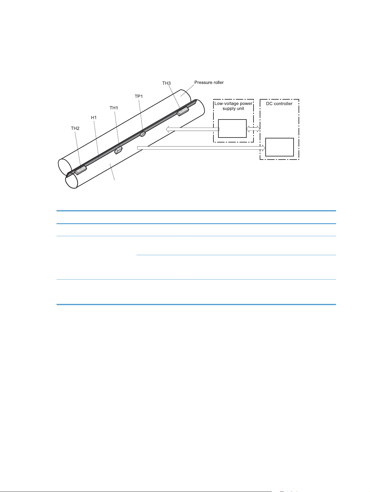
Fuser (fixing) control
The fuser-control circuit controls the fuser temperature. The product uses an on-demand fusing method.
Figure 1-6 Fuser (fixing) components
Fuser sleeve
Table 1-9 Fuser (fixing) components
Type of component Abbreviation Name Function
Fuser control
FUSER HEATING
CONTROL signal
FUSER TEMPERATURE signal
circuit
Fuser heater
safety circuit
Heaters H1 Fuser heater Heats the fuser sleeve.
Thermistors
(Contact type)
Thermoswitches
(Non-contact type)
TH1 Main thermistor The thermistor detects the center
temperature of the fuser sleeve.
TH2
TH3
TP1 For the fuser heater Controls the fuser-roller main
Sub thermistor Each thermistor detects the side
temperature of the fuser heater.
heater
16 Chapter 1 Theory of operation ENWW
Page 45

Fuser (fixing) temperature-control circuit
The temperatures of the two rollers in the fuser fluctuate according to the stage of the printing process.
The DC controller sends commands to the fuser-control circuit to adjust temperatures.
Figure 1-7 Fuser temperature-control circuit
Fuser
Fuser sleeve unit
Fuser heater
control circuit
Fuser heater safety
circuit
Fuser
Fuser heater safety circuit
Fuser (fixing) over-temperature protection
To protect the fuser from excessive temperatures, the product has four layers of protective functions. If
one function fails, the subsequent functions should detect the problem.
DC controller: When a thermistor or thermopile detects a temperature above a certain threshold,
●
the DC controller interrupts power to the specific heater. Following are the thresholds for each
component:
TH1: 230° C (446° F) or higher
◦
TH2: 285° C (545° F) or higher
◦
Fuser control circuit
Fuser
ENWW
TH3: 285° C (545° F) or higher
◦
Fuser (fixing)-heater safety circuit: If the DC controller fails to interrupt the power to the
●
heaters at the prescribed temperatures, the fuser-heater safety circuit deactivates the triac-drive
Engine-control system
17
Page 46

circuit and releases the relay, which causes the heaters to stop at slightly higher temperature
thresholds.
TH2: 290° C (554° F) or higher
◦
TH3: 290° C (554° F) or higher
◦
Current-detection protection circuit: If current flowing in each triac exceeds a specific value,
●
the current-detection protection circuit deactivates the triac-drive circuit and releases the relay,
which interrupts the power supply to the heaters.
Thermoswitch: If the temperature in the heaters is abnormally high, and the temperature in the
●
thermoswitches exceeds a specified value, the contact to the thermoswitch breaks. Breaking this
contact deactivates the triac-drive circuit and releases the relay, which interrupts the power supply
to the heaters. Following are the thresholds for each thermoswitch:
TP1: 270° C (518° F) or higher
◦
NOTE: When the thermoswitches reach this temperature, the temperature on the fuser rollers is about
320° C (608° F).
Fuser (fixing)-failure detection
When the DC controller detects any of the following conditions, it determines that the fuser has failed.
The DC controller then interrupts power to the fuser heaters and notifies the formatter.
Abnormally high temperatures: Temperatures are too high for any of the following
●
components, at any time:
TH1: 230° C (446° F) or higher
◦
TH2: 285° C (545° F) or higher
◦
TH3: 285° C (545° F) or higher
◦
Abnormally low temperatures: Temperatures are too low at any of the following
●
components after the product has initialized.
TH1: 120° C (248° F) or lower
◦
TP2 or TP3: 100° C (212° F) or lower
◦
Or, the temperature drops in either of the thermopiles (TP2 and TP3) by 30° C (86° F) or more
within a specified length of time.
Abnormal temperature rise: The DC controller determines an abnormal temperature rise if
●
the detected temperature of TH1 does not rise 2° C within a specified time period after the fuser
(fixing) motor is turned on, or if the detected temperature of the thermistors does not rise to a
specified temperature for a specified time after the fuser (fixing) motor is turned on.
18 Chapter 1 Theory of operation ENWW
Page 47

Thermistor open: The DC controller determines a thermistor open if:
●
The detected temperature of TH1 is kept at 12° C (53° F) or lower for a specified time after
◦
the fuser (fixing) motor is turned on.
The detected temperature of TH2 is kept at 4° C (39° F) or lower for a specified time.
◦
The detected temperature of TH3 is kept at 4° C (39° F) or lower for a specified time.
◦
Drive-circuit failure: The DC controller determines a drive-circuit failure:
●
If the detected power supply frequency is out of a specified range when the printer is turned
◦
on or during the standby period
If the current detection circuit detects an out of specified current value
◦
Fuser (fixing) discrepancy: The DC controller determines a fuser type mismatch when it
●
detects an unexpected fuser (fixing) unit presence signal. The product has two fusers for 110 V or
220 V input power.
ENWW
Engine-control system
19
Page 48

Laser/scanner system
The laser/scanner system forms the latent electrostatic image on the photosensitive drums according to
the VIDEO signals sent from the formatter. The product has two laser/scanners: one for yellow and
magenta and the other for cyan and black.
The formatter sends the DC controller instructions for the image of the page to be printed. The DC
controller signals the lasers to emit light, and the laser beams pass through lenses and onto the scanner
mirror, which rotates at a constant speed. The mirror reflects the beam onto the photosensitive drum in
the pattern necessary for the image, exposing the surface of the drum so it can receive toner.
Figure 1-8 Laser/scanner system
20 Chapter 1 Theory of operation ENWW
Page 49

The DC controller determines that a laser/scanner has failed when any of the following conditions
occurs:
Laser failure: The detected laser intensity does not match a specified value when the product
●
initializes.
Beam-detect (BD) failure: The BD interval is outside a specified range during printing.
●
Scanner-motor failure: The scanner motor does not reach a specified rotation speed within a
●
certain time after it begins rotating.
ENWW
Laser/scanner system
21
Page 50

Image formation system
The image-formation system creates the printed image on the paper. The system consists of the laser/
scanners, toner cartridges, imaging drums, ITB, and fuser.
Figure 1-9 Image formation system
Y
M
Fuser
C
Laser/scanner
K
Laser/scanner
22 Chapter 1 Theory of operation ENWW
Page 51

Image formation process
The image-formation system consists of ten steps divided into six functional blocks.
Figure 1-10 Image formation process
Y
M
Fusing
Fuser
C
K
Table 1-10 Image formation process
Functional block Steps Description
Latent image formation 1. Pre-exposure
2. Primary charging
3. Laser-beam exposure
Development 4. Development Toner adheres to the electrostatic latent
Transfer 5. Primary transfer
6. Secondary transfer
7. Separation
Fusing 8. Fusing The toner fuses to the paper to make a
ITB cleaning 9. ITB cleaning Residual toner is removed from the ITB.
Drum cleaning 10. Drum cleaning Residual toner is removed from the
An invisible latent image forms on the
surface of the photosensitive drums.
image on the photosensitive drums.
The toner image transfers to the ITB and
subsequently to the paper.
permanent image.
photosensitive drums.
ENWW
Image formation system
23
Page 52
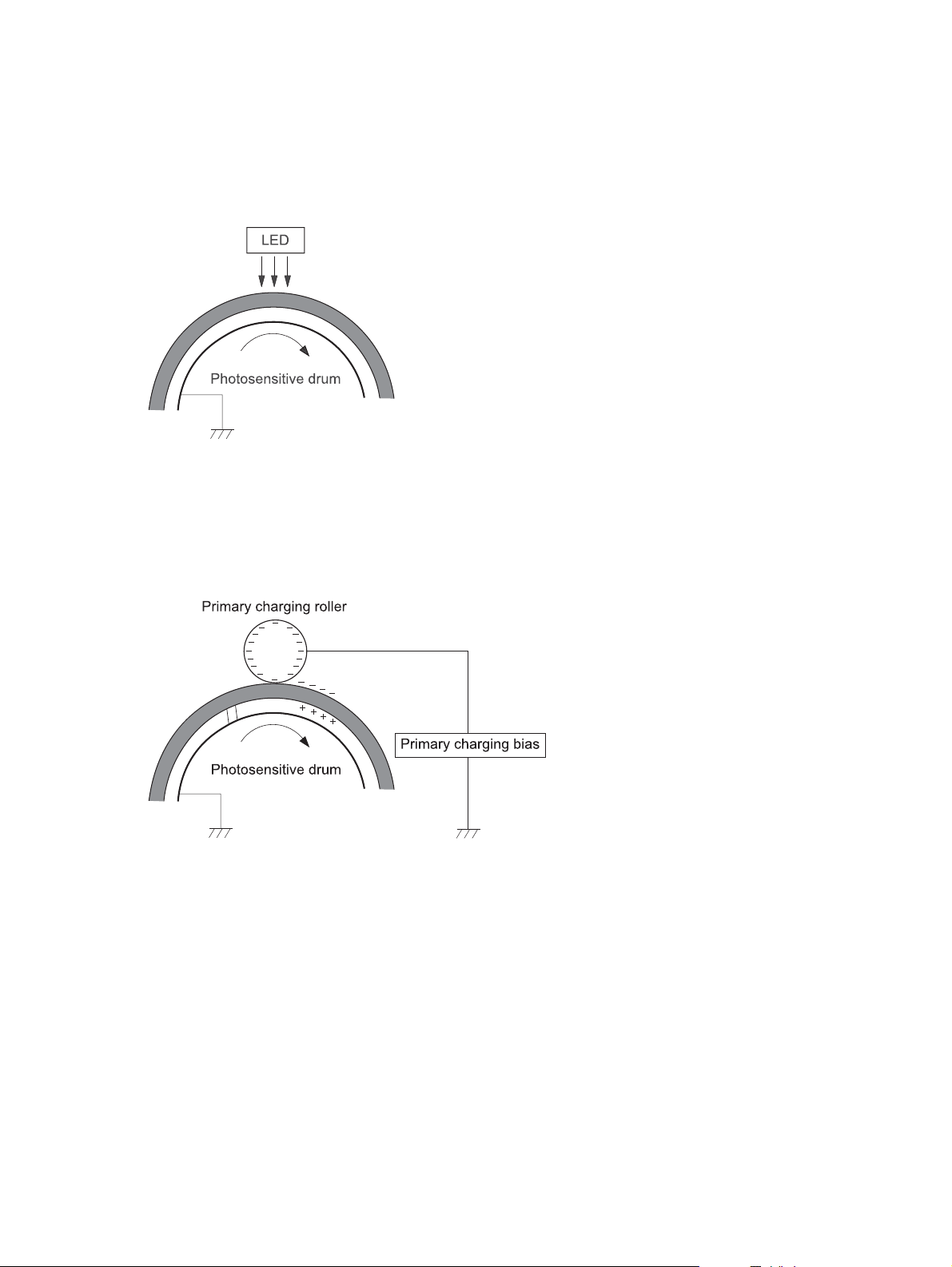
Step 1: Pre-exposure
Light from the pre-exposure LED strikes the surface of the photosensitive drum to remove any residual
electrical charges from the drum surface.
Figure 1-11 Pre-exposure
Step 2: Primary charging
The primary-charging roller contacts the photosensitive drum and charges the drum with negative
potential.
Figure 1-12 Primary charging
24 Chapter 1 Theory of operation ENWW
Page 53

Step 3: Laser-beam exposure
The laser beam strikes the surface of the photosensitive drum in the areas where the image will form.
The negative charge neutralizes in those areas, which are then ready to accept toner.
Figure 1-13 Laser-beam exposure
Step 4: Development
Toner acquires a negative charge as the developing cylinder contacts the developing blade. Because
the negatively charged surface of the photosensitive drums have been neutralized where they have
been struck by the laser beam, the toner adheres to those areas on the drums. The latent image
becomes visible on the surface of each drum.
Figure 1-14 Development
ENWW
Image formation system
25
Page 54

Step 5: Primary transfer
The positively charged primary-transfer rollers contact the ITB, giving the ITB a positive charge. The ITB
attracts the negatively charged toner from the surface of each photosensitive drum, and the complete
toner image transfers onto the ITB, beginning with yellow, followed by magenta, cyan, and black.
Figure 1-15 Primary transfer
Step 6: Secondary transfer
The paper acquires a positive charge from the secondary-transfer roller, and so it attracts the negatively
charged toner from the surface of the ITB. The complete toner image transfers onto the paper.
Figure 1-16 Secondary transfer
26 Chapter 1 Theory of operation ENWW
Page 55

Step 7: Separation
The stiffness of the paper causes it to separate from the ITB as the ITB bends. The static-charge
eliminator removes excess charge from the paper to ensure that the toner fuses correctly.
Figure 1-17 Separation
Step 8: Fusing
To create the permanent image, the paper passes through heated, pressurized rollers to melt the toner
onto the page.
Figure 1-18 Fusing
Fuser sleeve
Fuser heater
ENWW
Image formation system
27
Page 56

Step 9: ITB cleaning
The cleaning blade scrapes the residual toner off the surface of the ITB. The residual-toner-feed screw
deposits residual toner in the toner collection box.
Figure 1-19 ITB cleaning
Step 10: Drum cleaning
Inside the toner cartridge, the cleaning blade removes residual toner from the surface of the drum to
prepare it for the next image. The waste toner falls into the hopper in the print cartridge.
Figure 1-20 Drum cleaning
Toner cartridge
The product has four toner cartridges, one for each color. Each toner cartridge contains a reservoir of
toner and the following components:
Photosensitive drum
●
Developing roller
●
Primary-charging roller
●
28 Chapter 1 Theory of operation ENWW
Page 57
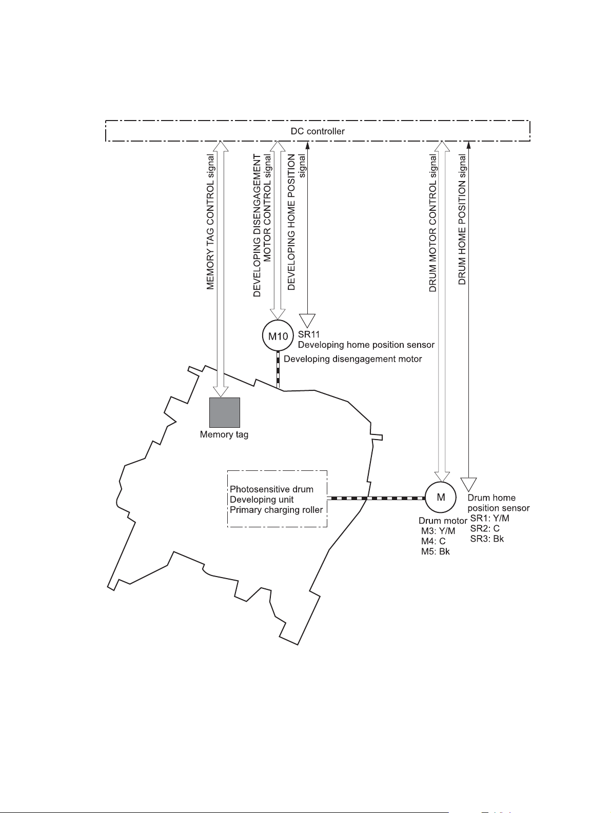
The DC controller rotates the drum motor to drive the photosensitive drum, developing roller, and the
primary-charging roller.
Figure 1-21 Toner-cartridge system
ENWW
The DC controller rotates the drum motor to drive the photosensitive drum, developing unit, and primary
charging roller.
The memory tag is a non-volatile memory chip that stores information about the usage for the toner
cartridge.
Image formation system
29
Page 58
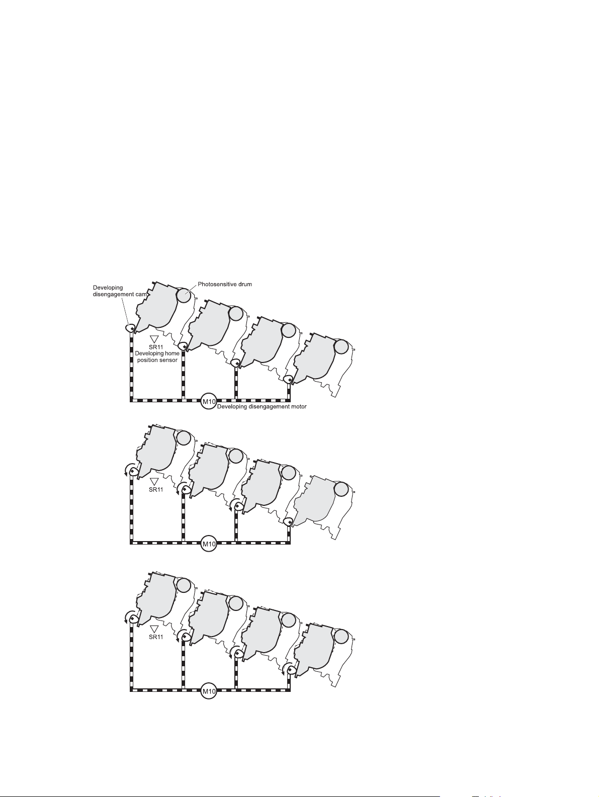
The DC controller notifies the formatter of an error if any of the following conditions exist:
The memory tag fails to either read to or write from the DC controller.
●
The RD sensors detect a missing or incorrectly installed toner cartridge.
●
The accumulated print time reaches a specified time period or the cartridge runs out of toner.
●
The toner level in any of the toner cartridges drops below a certain level.
●
Developing roller engagement and disengagement
The product can print in full-color mode or in black-only mode. To print in black-only mode, the product
disengages the developing rollers in the cyan, magenta, and yellow toner cartridges. This maximizes
the life of the cartridges.
Figure 1-22 Developing-roller engagement and disengagement control
Four developing units engaged
Y
Y
M
M
C
C
K
K
Only the Bk developing unit engaged
Y
Y
M
Four developing units disengaged
Y
Y
M
M
C
C
K
K
M
C
C
K
K
30 Chapter 1 Theory of operation ENWW
Page 59

The DC controller rotates the developing disengagement motor and changes the direction of the cam
according to the instructions from the formatter for each print job.
When the product is turned on and at the end of each print job, all four of the developing rollers
disengage from the photosensitive drums. If the next print job is full-color mode, each of the developing
rollers engage. If the next print job is black-only mode, only the black developing roller engages.
If the DC controller does not detect any output from the developing home-position sensor, it determines
that the developing-disengagement motor has failed.
ENWW
Image formation system
31
Page 60

Intermediate transfer belt (ITB) unit
The ITB unit accepts the toner images from the photosensitive drums and transfers the completed image
to the paper. The ITB unit has these main components:
ITB
●
ITB drive roller
●
ITB-driven roller
●
Primary-transfer rollers
●
ITB cleaner
●
The ITB motor drives the ITB drive roller, which rotates the ITB. The motion of the ITB causes the primary
transfer rollers to rotate. The ITB cleaner cleans the ITB surface.
Figure 1-23 ITB unit
C
K
M
Y
32 Chapter 1 Theory of operation ENWW
Page 61

Primary-transfer-roller engagement and disengagement
Depending on the requirements of the print job, the primary-transfer rollers engage with the ITB so it
can receive toner from the photosensitive drums.
Figure 1-24 Three states of primary-transfer-roller engagement and disengagement
Fuser motor
Four colors are disengaged
Y
FUSER MOTOR CONTROL
Y
Four colors are engaged
Y
Y
Only black is engaged
Y
Y
M
M
M
M
C
C
K
K
M
C
C
K
K
M
C
C
K
ENWW
Table 1-11 Primary-transfer-roller engagement states
Roller state Product state
All rollers disengaged The home position for the ITB unit
All rollers engaged The state for a full-color print job
Black roller engaged The state for a black-only print job
K
Image formation system
33
Page 62

The primary-transfer-roller disengagement motor rotates or reverses to place the primary-transfer-roller
disengagement cam into one of three positions. The cam causes the transfer-roller slide plate to move to
the right or left. This movement causes the primary-transfer rollers to move up to engage the ITB with the
photosensitive drum or down to disengage it.
If the DC controller does not receive the expected signal from the ITB home-position sensor when the
primary-transfer-roller engages or disengages, but the primary-transfer-roller disengagement motor is
rotating, the DC controller determines that the primary-transfer-disengagement mechanism has failed,
and notifies the formatter.
34 Chapter 1 Theory of operation ENWW
Page 63

ITB cleaning
The cleaning blade in the ITB cleaner scrapes the residual toner off the ITB surface. The drum motor
(M5) drives the residual toner feed screw. The screw feeds the residual toner to the residual toner feed
unit. The residual toner feed motor (M12) drives the residual toner feed screw. The residual toner feed
screw deposits the residual toner in the toner collection box. The DC control detects whether the toner
collection box is full, using the toner collection-box-full sensor, and then notifies the formatter.
Figure 1-25 ITB cleaning process
ENWW
Image formation system
35
Page 64

Calibration
The product calibrates itself to maintain excellent print quality. Calibration corrects color-misregistration
and color-density variation.
During calibration, the product places a specific pattern of toner on the surface of the ITB. Sensors at
the end of the ITB read the toner pattern to determine if adjustments are necessary.
Figure 1-26 Toner patterns for calibration
Color misregistration control
Internal variations in the laser/scanners can cause the toner images to become misaligned. The colormisregistration control corrects the following problems:
Horizontal scanning start position
●
Horizontal scanning magnification
●
Vertical scanning start position
●
The calibration occurs when any of the following occurs:
A cartridge is replaced.
●
The temperature of the sub thermistor is 50 C (122 F) or lower when the product recovers from
●
sleep mode after a specific number of pages print.
A specified number of pages have printed.
●
The formatter sends a command.
●
The user requests a calibration by using the control-panel menus.
●
36 Chapter 1 Theory of operation ENWW
Page 65

If data from the color-misregistration and image-density sensors is outside a specified range when the
product is turned on or when it is beginning the calibration sequence, the DC controller determines that
these sensors have failed, and it notifies the formatter.
Image stabilization control
Environmental changes or deterioration of the photosensitive drums and toner can cause variations in
the image density. The image-stabilization control reduces these fluctuations. There are three kinds of
image stabilization controls.
The formatter control is performed by the formatter.
Table 1-12 Image-stabilization controls
Image stabilization control Description
Environment change control The environment change control calibrates each high-voltage bias to obtain an
appropriate image according to the environment changes. The DC controller
determines the environment where the product is installed based on the surrounding
temperature and humidity data from the environment sensor, controls, and related
biases. This control occurs under the following circumstances:
The toner cartridge is replaced.
●
The DC controller notifies the formatter when it encounters a communication error
with the environmental sensor.
Image density control (DMAX) This control corrects variations in image density related to deterioration of the
photosensitive drum or the toner. The DC controller adjusts the high-voltage biases
to correct the problem under the following conditions:
The sub thermistor detects a temperature that is too low when the product is
●
turned on.
After the print operation is completed for a specific period of the time.
●
A toner cartridge is replaced.
●
The ITB is replaced.
●
A specified number of pages have printed.
●
The formatter sends a command.
●
The environment is relatively charged.
●
Image halftone control (DHALF) The image halftone control is performed by the formatter. The DC controller
measures the halftone pattern according to the command from the formatter. The
formatter performs this control to calibrate the halftone, based on the halftonedensity measurements, under the following conditions:
The formatter sends a command.
●
The DMAX is completed.
●
ENWW
The DC controller determines an RD sensor failure and notifies the formatter if it detects an out-ofspecified-data value from the RD sensor when the product is turned on or when the color misregistration
control starts.
Image formation system
37
Page 66

Pickup, feed, and delivery system
The pickup, feed, and delivery system uses a series of rollers to move the paper through the product.
Figure 1-27 Switches and sensors for the pickup, feed, and delivery system
Y
M
C
K
Table 1-13 Switches and sensors for the pickup, feed, and delivery system
Abbreviation Component
SR5 Fuser (fixing) delivery sensor
SR6 Delivery tray media full sensor
SR7 Fuser (fixing) pressure release sensor
SR8 TOP (top of page) sensor
SR9 Tray-media stack-surface sensor
SR13 Tray presence sensor
SR14 Loop sensor 1
SR15 Loop sensor 2
SR20 Tray media-presence sensor
38 Chapter 1 Theory of operation ENWW
Page 67

Table 1-13 Switches and sensors for the pickup, feed, and delivery system (continued)
Abbreviation Component
SR21 MP tray media-presence sensor
SR22 Duplex re-pickup sensor (duplex models only)
Figure 1-28 Motors and solenoids for the pickup, feed, and delivery system
Y
M
C
K
Table 1-14 Motors and solenoids for the pickup, feed, and delivery system
Abbreviation Component
M2 Fuser (fixing) motor
M5 Drum motor 3
ENWW
M7 Lifter motor
M11 Duplex reverse motor (duplex models only)
Pickup, feed, and delivery system
39
Page 68

Table 1-14 Motors and solenoids for the pickup, feed, and delivery system (continued)
Abbreviation Component
M13 Pickup motor
CL1 Duplex re-pickup clutch (duplex models only)
SL2 Duplex reverse solenoid (duplex models only)
SL3 Multipurpose tray pickup solenoid
SL4 Tray pickup solenoid
Figure 1-29 Three main units of the pickup, feed, and delivery system
Fuser/delivery block
Duplex block
Y
M
C
K
40 Chapter 1 Theory of operation ENWW
Page 69

Pickup-and-feed unit
The pickup-and-feed unit picks an individual sheet of paper from the multipurpose tray or the cassettes,
carries it through the secondary-transfer unit, and feeds it into the fuser.
Figure 1-30 Pickup-and-feed unit
Y
M
C
K
ENWW
Pickup, feed, and delivery system
41
Page 70

Tray pickup
The sequence of steps for the tray pickup operation is the following:
1. When the product starts or the tray closes, the lifting mechanism lifts the paper stack so it is ready.
2. After receiving a print command from the formatter, the DC controller rotates the pickup motor,
3. The DC controller drives the tray pickup solenoid, which rotates the tray pickup cam. As the
Figure 1-31 Tray-pickup mechanism
which causes the tray pickup roller, tray feed roller, and tray separation roller to rotate.
pickup cam rotates, the pickup arm moves down, and the tray pickup roller touches the surface of
the paper stack. The tray pickup roller then picks up one sheet of paper.
Tray
Tray
Tray
NOTE: The lift-up operation lifts the lifting plate to keep the stack surface of the media at a pickup
position. The lifting spring helps support the lifting plate depending on the media size and amount.
42 Chapter 1 Theory of operation ENWW
Page 71

Tray-presence detection
The tray presence sensor is in the lifter drive unit. The sensor detects the tray-presence sensor flag and
determines whether the tray is installed correctly.
Figure 1-32 Tray presence sensor
Tray
Tray lift operation
The DC controller rotates the lifter motor (M7) and moves the lifter rack until the tray media stack
surface sensor (SR9) detects it. The lifter lifts, and the lifting plate moves up to the position where the
media can be picked up. The lift operation is performed by monitoring the media stack surface sensor
when the printer is turned on, when the tray is installed, or as needed during a print operation.
If the paper-stack surface sensor does not detect the paper within a specified time after the lifter motor
begins rotating, the DC controller notifies the formatter that the lifter motor has failed.
Tray
ENWW
Pickup, feed, and delivery system
43
Page 72

The DC controller lowers the lifting plate when no printing occurs to prevent media damage and pickup
failure. If a print operation does not occur for a specified time, the DC controller reverses the lifter
motor and moves the lifter rack until the tray media-stack surface sensor stops detecting it.
Figure 1-33 Tray lift mechanism
Tray
Tray
44 Chapter 1 Theory of operation ENWW
Page 73

paper-presence detection
The media presence sensor detects whether paper is in the .
Figure 1-34 Paper-level-detection mechanism
Tray
Tray
Multifeed prevention
In the , a separation roller prevents multiple sheets of paper from entering the paper path. The pickup
roller drives the separation roller through a sheet of paper.
Tray
ENWW
The low friction force between the sheets weakens the driving force from the pickup roller. Because
some braking force is applied to the separation roller, the weak rotational force of the pickup roller is
not enough to rotate the separation roller. Therefore, the separation roller holds back any multiple-fed
sheets, and one sheet of media is fed into the printer.
Figure 1-35 Multifeed prevention
Cassette pickup
roller
Cassette
separation
roller
Normal feed
Lifting plate
Media
Separation roller does not rotate
Multiple feed
Pickup, feed, and delivery system
45
Page 74

Multipurpose tray pickup
The multipurpose tray (MP) paper-presence sensor detects whether paper is in the tray. If no paper is
present, the DC controller notifies the formatter. Printing does not occur until paper is in the tray.
The sequence of steps for the multipurpose tray pickup operation as follows:
1. After receiving a print command from the formatter, the DC controller reverses the pickup motor,
which causes the multipurpose tray separation roller to rotate.
2. The DC controller turns on the multipurpose tray pickup solenoid (SL3), causing the multipurpose
tray pickup roller to rotate.
3. The multipurpose tray separation roller isolates a single sheet of paper in case more than one
sheet was picked. The single sheet of paper feeds into the product.
The MP-tray media-presence sensor (SR21) detects whether the media is present in the MP tray. No
printing occurs if no media is loaded.
Figure 1-36 Multipurpose tray pickup mechanism
46 Chapter 1 Theory of operation ENWW
Page 75

Paper feed
After the pickup operation, the paper feeds through the product and into the fuser.
1. The paper passes through the feed rollers. The registration shutter aligns the paper correctly to
2. The DC controller detects the leading edge of paper by the Top sensor (SR8) and controls the
3. The DC controller detects whether or not the media is overhead transparency, using the OHT
4. The toner image on the ITB transfers onto the media, which feeds to the fuser.
Figure 1-37 Paper-feed mechanism
prevent skewed printing.
rotational speed of the pickup motor to align with the leading edge of image on the ITB.
sensor.
ENWW
Pickup, feed, and delivery system
47
Page 76
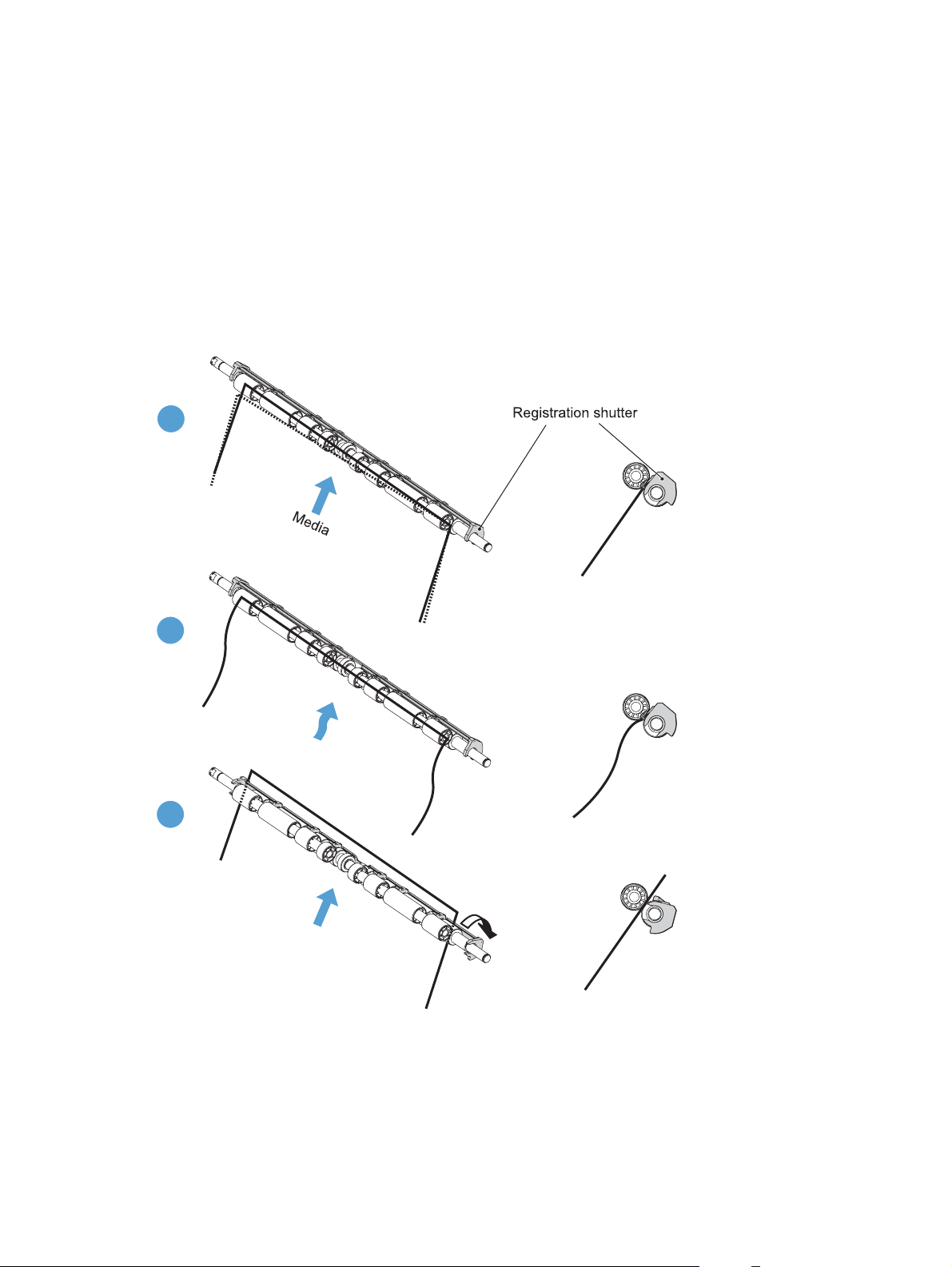
Skew-feed prevention
The product can straighten the paper without slowing the feed operation.
1. As the paper enters the paper path, the leading edge strikes the registration shutter, which
straightens the paper. The paper does not pass through the shutter.
2. The feed rollers keep pushing the paper, which creates a force on the leading edge against the
registration shutter.
3. When the force is great enough, the registration shutter opens and the paper passes through.
Figure 1-38 Skew-feed prevention
1
2
3
OHT detection
The OHT sensor detects overhead transparencies. The OHT sensor is a transmission sensor that uses an
LED. The DC controller determines a media mismatch and notifies the formatter when the media type
differs from the media type detected by the OHT sensor. The DC controller turns the LED in the OHT
48 Chapter 1 Theory of operation ENWW
Page 77
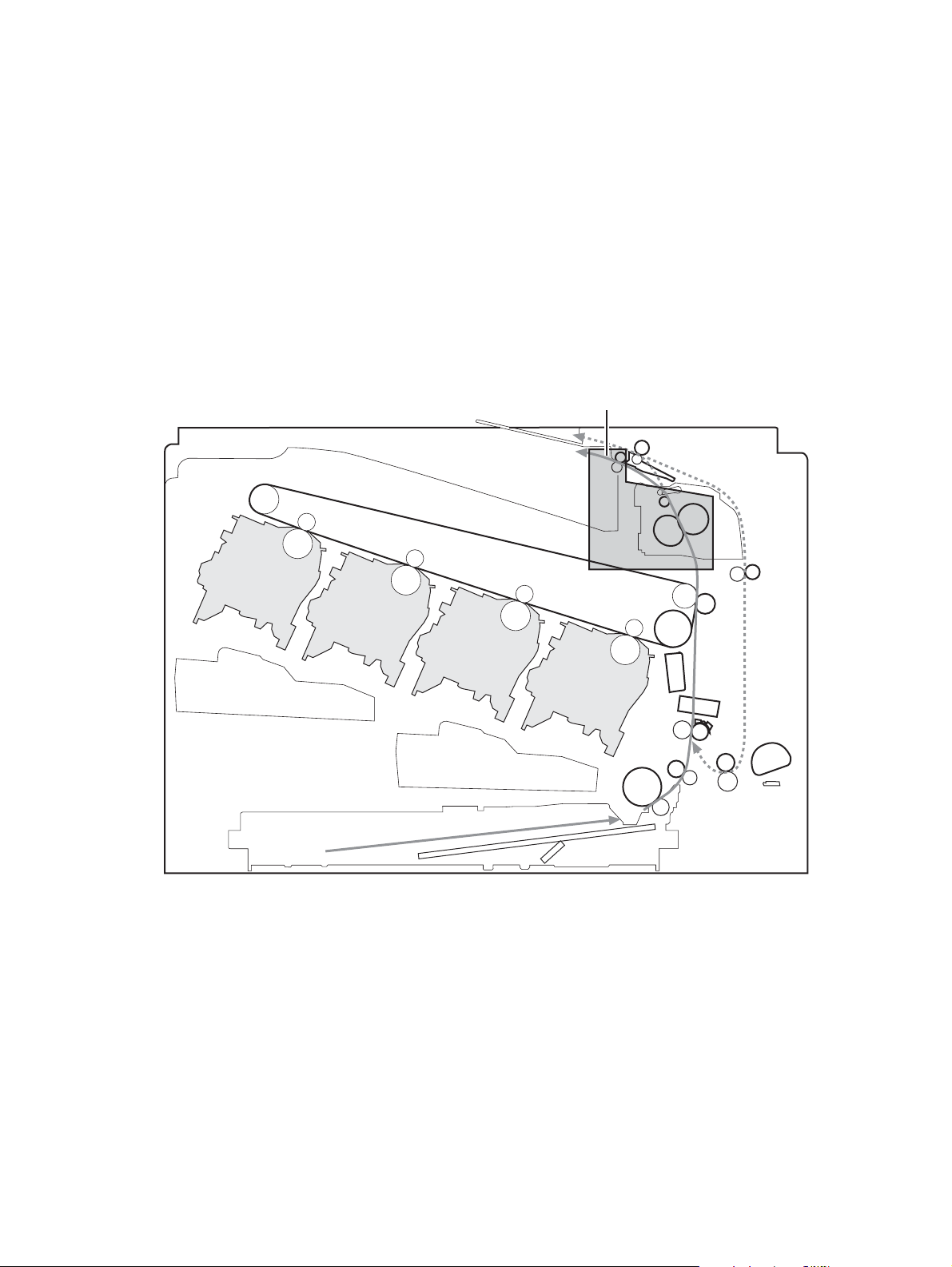
sensor on and off during the wait or initial rotation period. If the intensity of the light does not match the
specified value, the DC controller determines that the OHT sensor has failed.
Fusing and delivery unit
The fusing and delivery unit fuses the toner onto the paper and delivers the printed page into the output
bin. The following controls ensure optimum print quality:
Loop control
●
Pressure roller pressurization/depressurization control
●
A sensor detects when the output bin is full, and the DC controller notifies the formatter.
Figure 1-39 Fuser and delivery unit
Fuser/delivery block
Loop control
The loop control monitors the tension of the paper between the secondary-transfer roller and the fuser.
If the fuser rollers rotate more slowly than the secondary transfer rollers, the paper warp increases
●
and an image defect or paper crease occurs.
Y
M
C
K
ENWW
If the fuser rollers rotate faster than the secondary transfer rollers, the paper warp decreases and
●
the toner image fails to transfer to the paper correctly, causing color misregistration.
Pickup, feed, and delivery system
49
Page 78

To prevent these problems, the loop sensors, which are located between the secondary transfer rollers
and the fuser rollers, detect whether the paper is sagging or is too taut. The DC controller adjusts the
speed of the fuser motor.
Figure 1-40 Loop-control mechanism
50 Chapter 1 Theory of operation ENWW
Page 79

Pressure-roller pressurization control
To prevent excessive wear on the pressure roller and help with jam-clearing procedures, the pressure
roller pressurizes only during printing and standby. The DC controller reverses the fuser motor. The
fuser motor rotates the fuser pressure-release cam.
Figure 1-41 Pressure-roller pressurization control
FUSER MOTOR CONTROL
Fuser motor
FUSER PRESSURE RELEASE signal
Fuser pressure release cam
Fuser sleeve
The pressure roller depressurizes under the following conditions:
The product is turned off with the on/off switch
●
Any failure occurs other than a fuser pressure-release mechanism failure
●
ENWW
During powersave mode
●
When a paper jam is detected
●
If the DC controller does not sense the fuser pressure-release sensor for a specified period after it
reverses the fuser motor, it notifies the formatter that a fuser pressure-release mechanism failure has
occurred.
NOTE: The fuser remains pressurized if the power is interrupted when the power cord is removed or
the surge protector is turned off, or if the fuser is removed without turning off the product.
Pickup, feed, and delivery system
51
Page 80

Duplexing unit
The duplexing unit reverses the paper and feeds it through the paper path to print the second side. The
duplexing unit consists of the following components:
Duplexing-reverse unit: Installed on top of the product
●
Duplexing-feed unit: Along the right side
●
The DC controller controls the operational sequence of the duplex block. The DC controller drives each
load, such as motors, solenoid, and clutch, depending on the duplex-reverse unit and duplex-feed unit
controls.
Figure 1-42 Duplexing unit
52 Chapter 1 Theory of operation ENWW
Page 81

Duplexing reverse and feed control
The duplexing reverse procedure pulls the paper into the duplexing unit after it exits the fuser. The
duplexing feed procedure moves the paper through the duplexer so it can enter the product paper path
to print the second side of the page.
1. After the first side has printed, the duplexing flapper solenoid opens, which creates a paper path
into the duplexing-reverse unit.
2. After the paper has fully entered the duplexing-reverse unit, the duplexing-reverse motor reverses
and directs the paper into the duplexing-feed unit.
3. The duplexing re-pickup motor and duplexing feed motor move the paper into the duplexing re-
pickup unit.
4. To align the paper with the toner image on the ITB, the duplexing re-pickup motor stops and the
paper pauses.
5. The paper re-enters the paper path, and the second side prints.
Duplex pickup operation
The product has the following two duplex-media-feed modes depending on the media sizes:
One-sheet mode: Prints one sheet that is printed on two sides in one duplex print operation
●
Two-sheet mode: Prints two sheets that are printed on two-sides in one duplex print operation
●
(maximum paper size is A4)
The formatter specifies the duplex-media-feed mode.
ENWW
Pickup, feed, and delivery system
53
Page 82

Jam detection
The product uses the following sensors to detect the paper as it moves through the paper path and to
report to the DC controller if the paper has jammed.
Fuser output sensor (SR5)
●
Registration sensor (SR8)
●
Fuser loop 1 (SR14)
●
Fuser loop 2 (SR15)
●
Duplexer refeed (SR22)
●
Figure 1-43 Jam detection sensors
Y
M
C
K
The product determines that a jam has occurred if one of these sensors detects paper at an
inappropriate time. The DC controller stops the print operation and notifies the formatter.
Table 1-15 Jams that the product detects
Jam Description
Pickup delay jam 1 pickup: The TOP sensor does not detect the leading edge of the paper within a specified
period after the pickup solenoid has turned on.
Multipurpose tray pickup: The TOP sensor does not detect the leading edge of the paper
within a specified period after the multipurpose tray solenoid has turned on.
Pickup stationary jam The TOP sensor does not detect the trailing edge of the paper within a specified time from
when it detects the leading edge.
54 Chapter 1 Theory of operation ENWW
Page 83

Table 1-15 Jams that the product detects (continued)
Jam Description
Fuser delivery delay jam The fuser delivery paper-feed sensor does not detect the leading edge of the paper within a
specified period after the TOP sensor detects the leading edge.
Fuser delivery stationary jam The fuser delivery paper-feed sensor does not detect the trailing edge of the paper within a
specified period after it detects the leading edge.
Wrapping jam After detecting the leading edge of the paper, the fuser delivery paper-feed sensor detects the
absence of paper, and it has not yet detected the trailing edge.
Residual paper jam One of the following sensors detects paper presence during the initialization sequence:
Fuser delivery paper-feed sensor
●
TOP sensor
●
Loop sensor 1
●
Loop sensor 2
●
Duplex re-feed
●
Door open jam A door is opened while paper is moving through the product.
Duplexing re-pickup jam 1 The duplex re-pickup sensor does not detect the leading edge of the paper within a specified
period after the media reverse operation starts in the duplex-reverse unit.
Duplexing re-pickup jam 2 The TOP sensor does not detect the leading edge of the paper within a specified period after
the paper is re-picked.
After a jam, some sheets of paper might remain inside the product. If the DC controller detects residual
paper after a door closes or after the product is turned on, the product automatically clears itself of
those residual sheets.
ENWW
Jam detection
55
Page 84

Optional paper feeder
The 1x500-sheet paper feeder is optionally installed underneath the product. The paper feeder picks up
the print media and feeds it to the printer.
NOTE: These optional trays are not identical to the main (Tray 2).
Figure 1-44 Optional paper feeder
Y
M
C
K
The paper-deck drivers contain a microcomputer and control the paper feeder. The paper-deck drivers
receive commands from the DC controller. If the DC controller is unable to communicate with a paperdeck driver, it notifies the formatter that the optional paper feeders are not connected correctly.
56 Chapter 1 Theory of operation ENWW
Page 85

Figure 1-45 Signals for the paper feeder
The input trays contain several motors, solenoids, sensors, and switches, as described in the following
table.
Table 1-16 Electrical components for the paper feeder
Component
type
Motors M1 Paper feeder motor
Solenoids SL1 Paper feeder pickup solenoid
Sensors SR1 Tray 3 installed sensor
Switches SW1 Paper feeder media-size switch
Abbreviation Component name
M2 Paper feeder lift motor
SR2 Tray 3 stack surface sensor 2
SR3 Tray 3 paper present sensor
SR4 Tray 3 feed sensor
SW2 Paper-feeder door switch
ENWW
Optional paper feeder
57
Page 86

Paper-feeder pickup and feed operation
The paper feeder picks up one sheet from the paper-feeder and feeds it to the product.
Figure 1-46 Paper-feeder pickup and feed operation
58 Chapter 1 Theory of operation ENWW
Page 87

Paper size detection and presence detection
The paper-feeder media-size switch (SW1) detects the size of paper loaded in the paper-feeder . The
paper-feeder driver determines the media size by monitoring the combination of the switches.
Figure 1-47 Paper size detection
ENWW
Tray
Optional paper feeder
59
Page 88

Table 1-17 Paper size detection
Paper size Paper-feeder media-size switch settings
Top switch Center switch Bottom switch
Universal On On On
A5 On Off Off
B5 Off On On
Executive On Off On
Letter Off On Off
A4 Off Off On
Legal On On Off
No Off Off Off
The paper-feeder media size switch (SW1) detects whether the paper-feeder is installed correctly. The
paper-feeder driver determines if a is absent when all three switches are turned off. The paper-feeder
driver determines a presence when one of the switches is turned on.
60 Chapter 1 Theory of operation ENWW
Page 89

Paper feeder lift operation
The lift operation keeps the stack surface of paper at a specified height to maintain stable media
feeding. The paper-feeder driver controls the paper-feeder lifter motor (M2) and monitors the paperfeeder media stack surface sensors (SR1, SR2) to adjust the stack height when the printer is turned on,
when the printer recovers from sleep mode, when the paper-feeder is installed or as needed during a
print operation. The paper feeder has two paper-feeder media-stack surface sensors. The paper-feeder
media stack surface sensor 1 detects the stack height during a print operation. The paper-feeder mediastack surface sensor 2 detects the stack height when the printer is turned on, when the printer recovers
from sleep mode and when the paper-feeder is installed. The operational sequence of the lift operation
is as follows:
1. The paper-feeder driver rotates the paper-feeder lifter motor to lift the lifting plate.
2. The paper-feeder driver stops the paper-feeder lifter motor when the paper-feeder media-stack
surface sensor 2 detects the stack surface.
3. The paper-feeder driver rotates the lifter motor again when paper-feeder media stack surface 1
detects that the media surface is lowered during a print operation.
Figure 1-48 Paper-feeder lift
ENWW
The paper-feeder driver notifies the formatter if either of the paper-feeder media-stack surface sensors
fails to detect the stack surface within a specified period from when a lift-up operation starts.
Optional paper feeder
61
Page 90

Paper feeder presence detection
The Tray 3 paper present (SR3) detects whether the paper is present in the paper-feeder .
Paper-feeder multiple feed prevention
The paper-feeder uses a separation roller to prevent multiple sheets of paper from entering the printer.
The separation roller prevents multiple feeds of paper by allowing the paper-feeder separation roller to
rotate in the same direction as the paper-feeder feed roller 1. The paper-feeder separation roller is
equipped with the torque limiter. If multiple sheets of paper are picked up, the torque limiter takes
control of the paper-feeder separation roller, and pushes the extra sheets back to the paper-feeder .
That way, only the top sheet is fed to the printer.
Figure 1-49 Paper-feeder multiple feed prevention
No-load Rotational force for paper-feeder separation roller: Pushes
back the media into the paper-feeder
Rotational force for paper-feeder feed roller 1: Feeds media
into the printer
62 Chapter 1 Theory of operation ENWW
Page 91

Normal feed Rotational force for paper-feeder separation roller: Pushes
back the media into the paper-feeder
Rotational force for paper-feeder feed roller 1: Feeds media
into the printer
Multiple-feed The low friction force between the sheets weakens the
rotational force from the paper-feeder feed roller 1.
The paper-feeder separation roller rotates by its own
rotational force and removes the extra sheet.
ENWW
Optional paper feeder
63
Page 92

Paper feeder jam detection
The paper feeder uses the Tray 3 feed (SR4) to detect the presence of paper and to check whether
paper has jammed.
Figure 1-50 Jam detection
Y
M
C
K
The paper-feeder driver identifies a jam if the sensor detects paper at a specified timing stored in the
paper-feeder driver. The paper-feeder driver stops printing and notifies the formatter through the DC
controller of the jam. The paper feeder detects the following jams:
Pickup delay jam: The paper-feeder media-feed sensor does not detect the leading edge of media
●
within a specified period from when the paper-feeder pickup solenoid is turned on.
Pickup stationary jam: The paper-feeder media-feed sensor does not detect the trailing edge of
●
media within a specified time period from when the sensor detects the leading edge.
64 Chapter 1 Theory of operation ENWW
Page 93

Scanning/image capture system
Control panel
The control panel is an 8 in full color SVGA (800 x 600 LCD) with capacitive touchscreen and
adjustable viewing angle. The control panel includes a USB port for walk-up printing and a hardware
integration pocket for third-party USB devices such as card readers.
The control panel has a diagnostic mode to allow testing of the touchscreen, home button, and speaker.
The control panel does not require calibration.
Scanner
The scanner is a carriage-type platen scanner which includes the frame, glass, LED optics, and a
scanner controller board (SCB) attached to the back of the assembly. The scanner has a sensor to
detect legal-sized media and a switch to indicate when the ADF is opened.
The ADF and control-panel assembly are attached to the scanner assembly. If the scanner fails, it can
be replaced as a whole unit. The scanner replacement part does not include the ADF, SCB, or controlpanel assembly.
Automatic document feed system
Simplex single pass
●
Duplex three pass
●
Legal-sensing flag
●
Pick and feed roller assembly with separation pad
●
Mechanical deskew
●
Step glass for ADF scanning
●
Jam clearance door with sensing
●
LED indication when original is placed on input tray
●
Sensors in the ADF
The ADF contains the following sensors:
ADF-cover sensor: Detects whether the ADF cover is open or closed.
●
Paper length sensor: Detects whether there is a legal-size original.
●
Pick success sensor: Detects the top of the page before sending a page through the ADF and
●
the end of the page after feeding/scanning is complete.
ENWW
Paper-present sensor: Detects whether a document is present in the ADF. If paper is present in
●
the ADF when copies are made, the product scans the document using the ADF. If no paper is
present when copies are made, the product scans the document using the scanner glass.
Scanning/image capture system
65
Page 94

Deskew sensor: Detects the top of the page as it enters the deskew. rollers
●
Path sensor 1: Detects the top of the page as it approaches the ADF glass.
●
ADF paper path
The ADF feeds documents past the ADF glass for scanning.
Figure 1-51 ADF path for single-sided documents
1 Separation pad 5 ADF input tray
2 Pickup roller 6 Delivery/duplex-feed rollers
3Stack stop 7ADF glass
4 Pre-pick roller 8 ADF feed rollers
For two-sided documents, the delivery rollers reverse the direction of each page to feed the second side
of the document past the ADF glass.
66 Chapter 1 Theory of operation ENWW
Page 95

Figure 1-52 ADF path for two-sided documents
3 4 5
1
2
6
8
7
NOTE: Callouts in Figure 1-52 ADF path for two-sided documents on page 67 are identical to
callouts in
Figure 1-51 ADF path for single-sided documents on page 66 .
Stapler (stapling models only)
The product includes a stapler capable of stapling 20 sheets of (75 g/m2) (20 lb) paper. The stapler is
powered by a +24v connection from the DC controller. Because there are no logic connections to the
product, error conditions or out-of-staples indications are not displayed on the control panel.
ENWW
Scanning/image capture system
67
Page 96

68 Chapter 1 Theory of operation ENWW
Page 97

2 Solve problems
NOTE: To perform diagnostic and configuration procedures (for example, resetting page counts) for
the product, you must install the CP1210 Service Config Tool (available at your HP authorized repair
center).
Solve problems checklist
●
Menu map
●
Preboot menu options
●
Current settings pages
●
Troubleshooting process
●
Tools for troubleshooting
●
Clear jams
●
Paper feeds incorrectly or becomes jammed
●
Use manual print modes
●
Solve image quality problems
●
Clean the product
●
Solve performance problems
●
Solve connectivity problems
●
Service mode functions
●
Solve fax problems
●
Product upgrades
●
ENWW 69
Page 98

Solve problems checklist
Follow these steps when trying to solve a problem with the product.
1. If the control panel is blank or black, complete these steps:
a. Check the power cable.
b. Check that the power is turned on.
c. Make sure that the line voltage is correct for the product power configuration. (See the label
that is on the back of the product for voltage requirements.) If you are using a power strip
and its voltage is not within specifications, connect the product directly into the electrical
outlet. If it is already connected into the outlet, try a different outlet.
2. The control panel should indicate a Ready status. If an error message displays, resolve the error.
3. Check the cabling.
a. Check the cable connection between the product and the computer or network port. Make
sure that the connection is secure.
b. Make sure that the cable itself is not faulty by using a different cable, if possible.
c. Check the network connection.
4. Ensure that the selected paper size and type meet specifications. Also open the Trays menu on the
product control panel and verify that the tray is configured correctly for the paper type and size.
5. Print a configuration page. If the product is connected to a network, an HP Jetdirect page also
prints.
a. From the Home screen on the product control panel, scroll to and touch the Administration
button.
b. Open the following menus:
Reports
◦
Configuration/Status Pages
◦
Configuration Page
◦
c. Touch the Print button to print the page.
If the pages do not print, check that at least one tray contains paper.
If the page jams in the product, follow the instructions on the control panel to clear the jam.
If the page does not print correctly, the problem is with the product hardware.
If the page prints correctly, then the product hardware is working. The problem is with the
computer you are using, with the print driver, or with the program.
6. Verify that you have installed the print driver for this product. Check the program to make sure that
you are using the print driver for this product. The print driver is on the CD that came with the
70 Chapter 2 Solve problems ENWW
Page 99

product. You can also download the print driver from this Web site: www.hp.com/go/
lj500colorMFPM575_software.
7. Print a short document from a different program that has worked in the past. If this solution works,
then the problem is with the program. If this solution does not work (the document does not print),
complete these steps:
a. Try printing the job from another computer that has the product software installed.
b. If you connected the product to the network, connect the product directly to a computer with
a USB cable. Redirect the product to the correct port, or reinstall the software, selecting the
new connection type that you are using.
ENWW
Solve problems checklist
71
Page 100

Menu map
You can print a report of the complete Administration menu so you can more easily navigate to the
individual settings you need.
1. From the Home screen on the product control panel, scroll to and touch the Administration button.
2. Open the following menus:
Reports
●
Configuration/Status Pages
●
3. Select the Administration Menu Map option.
4. Touch the Print button to print the report.
72 Chapter 2 Solve problems ENWW
 Loading...