

Page 1
Troubleshooting Manual
Color LaserJet Enterprise M552
Color LaserJet Enterprise M553
www.hp.com/support/colorlj552
www.hp.com/support/colorlj553
www.hp.com/support/colorljM577MFP
For printer part removal and part number
information, see the Repair Manual.
M553xM552dn
M553dn
M553n
M577dn
M577f
M577c
M577z
Color LaserJet Enterprise MFP M577
Page 2

Page 3

HP Color LaserJet Enterprise M553, HP Color
LaserJet Enterprise M552, and HP Color
LaserJet Enterprise MFP M577
Troubleshooting Manual
Page 4

Copyright and License
Trademark Credits
© Copyright 2015 HP Development Company,
L.P.
Reproduction, adaptation, or translation
without prior written permission is prohibited,
except as allowed under the copyright laws.
The information contained herein is subject to
change without notice.
The only warranties for HP products and
services are set forth in the express warranty
statements accompanying such products and
services. Nothing herein should be construed
as constituting an additional warranty. HP shall
not be liable for technical or editorial errors or
omissions contained herein.
Edition 1, 11/2015
Microsoft®, Windows®, Windows® XP, and
Windows Vista® are U.S. registered trademarks
of Microsoft Corporation.
Page 5

Conventions used in this guide
TIP: Helpful hints or shortcuts.
NOTE: Information that explains a concept or how to complete a task.
Reinstallation tip: Reinstallation helpful hints, shortcuts, or considerations.
IMPORTANT: Information that help the user to avoid potential printer error conditions.
CAUTION: Procedures that the user must follow to avoid losing data or damaging the printer.
WARNING! Procedures that the user must follow to avoid personal injury, catastrophic loss of data, or
extensive damage to the printer.
ENWW iii
Page 6

iv Conventions used in this guide ENWW
Page 7

For additional service and support information
HP service personnel, go to the Service Access Work Bench (SAW) at http://h41302.www4.hp.com/km/saw/
home.do.
Channel partners, go to HP Channel Services Network (CNS) at https://h30125.www3.hp.com/hpcsn.
At these locations, nd information on the following topics:
●
Install and congure
●
Printer specications
●
Up-to-date control panel message (CPMD) troubleshooting
●
Solutions for printer issues and emerging issues
●
Remove and replace part instructions and videos
●
Service advisories
●
Warranty and regulatory information
To access HP PartSurfer information from any mobile device, go to http://partsurfermobile.hp.com/ or scan
the Quick Response (QR) code below.
ENWW v
Page 8

vi For additional service and support information ENWW
Page 9

Table of contents
1 Theory of operation ....................................................................................................................................... 1
For additional service and support ........................................................................................................................ 2
Basic operation ...................................................................................................................................................... 3
Sequence of operation ........................................................................................................................ 5
Formatter-control system ..................................................................................................................................... 7
Sleep mode .......................................................................................................................................... 7
Printer job language (PJL) ................................................................................................................... 8
Printer management language (PML) ................................................................................................. 8
Control panel ....................................................................................................................................... 8
Easy-access USB port .......................................................................................................................... 9
Wireless ............................................................................................................................................... 9
Near eld communication (NFC) .......................................................................................................... 9
CPU ....................................................................................................................................................... 9
Input/output (I/O) ................................................................................................................................ 9
Memory ................................................................................................................................................ 9
Firmware ......................................................................................................................... 10
Nonvolatile random access memory (NVRAM) ............................................................... 10
Random access memory (RAM) ...................................................................................... 10
HP Memory Enhancement technology (MEt) .................................................................. 10
Engine-control system ........................................................................................................................................ 11
DC controller ...................................................................................................................................... 12
Motors ............................................................................................................................. 13
Fans ................................................................................................................................. 14
Solenoids ......................................................................................................................... 14
Clutches ........................................................................................................................... 14
Switches .......................................................................................................................... 14
Sensors ........................................................................................................................... 16
Low-voltage power supply ................................................................................................................ 18
Low-voltage power supply voltages description ........................................................... 19
Over-current/over-voltage protection ........................................................................... 19
Sleep mode operation ..................................................................................................... 19
Low-voltage power supply failure detection ................................................................. 20
ENWW vii
Page 10

Low-voltage power supply functions ............................................................................. 20
High-voltage power supply ............................................................................................................... 20
High-voltage power supply circuits ................................................................................ 21
Fuser bias ........................................................................................................................ 22
Fuser control ..................................................................................................................................... 22
Fuser circuits ................................................................................................................... 22
Fuser control functions ................................................................................................... 24
Fuser temperature control ............................................................................................. 24
Fuser heater protection .................................................................................................. 26
Fuser unit life detection .................................................................................................. 26
Fuser identication ......................................................................................................... 26
Engine laser/scanner system .............................................................................................................................. 27
Laser/scanner failure detection ........................................................................................................ 28
Safety ................................................................................................................................................ 28
Image-formation process ................................................................................................................. 29
Step 1: Pre-exposure ...................................................................................................... 35
Step 2: Primary charging ................................................................................................ 35
Step 3: Laser-beam exposure ......................................................................................... 36
Step 4: Development ...................................................................................................... 36
Step 5: Primary transfer ................................................................................................. 37
Step 6: Secondary transfer ............................................................................................. 37
Step 7: Separation ........................................................................................................... 38
Step 8: Fusing .................................................................................................................. 38
Step 9: ITB cleaning ......................................................................................................... 39
Step 10: Drum cleaning ................................................................................................... 39
Toner cartridges ................................................................................................................................ 40
Design ............................................................................................................................. 40
Memory chip .................................................................................................................... 42
Toner seal ........................................................................................................................ 42
Toner level and cartridge life detection .......................................................................... 42
Developing unit engagement and disengagement control ........................................... 42
Cartridge Authentication Technology (CAT) ................................................................... 43
Authentication .............................................................................................. 44
Anti-theft ...................................................................................................... 44
Intermediate transfer belt (ITB) unit ................................................................................................. 45
Primary-transfer roller engagement and disengagement control ................................ 45
ITB unit detection ............................................................................................................ 47
ITB cleaning mechanism ................................................................................................. 48
Secondary transfer roller functions ............................................................................... 48
Calibration ....................................................................................................................... 49
Pickup, feed, and delivery system ....................................................................................................................... 50
viii ENWW
Page 11

Photo sensors and switches ............................................................................................................. 51
Motors, clutches, and solenoids ........................................................................................................ 53
Tray 1 (multipurpose)/Tray 2 (base printer) ..................................................................................... 54
Tray 1 paper pickup and feed ......................................................................................... 54
Tray 2 paper presence detection .................................................................................... 55
Tray 2 lift operation ........................................................................................................ 55
Tray 2 paper pickup ......................................................................................................... 56
Tray 2 multiple-feed prevention ..................................................................................... 56
Tray 2 presence detection .............................................................................................. 57
Tray 2 skew feed prevention ........................................................................................... 57
Tray 2 media type detection ........................................................................................... 58
Feed speed control .......................................................................................................... 59
Duplexing unit (M552dn, M553dn, M553x, and M577 only) ............................................................ 60
Duplexing reverse and duplex feed control ................................................................... 60
Jam detection/prevention ................................................................................................................. 60
Fuser wrapping jam detection ........................................................................................ 62
Loop control .................................................................................................. 62
Pressure roller pressurization and depressurization control ...................... 63
Input accessories ................................................................................................................................................. 65
Trays 3-5 ........................................................................................................................................... 65
Trays 3-5 driver PCA ....................................................................................................... 65
Trays 3-5 motor control .................................................................................................. 66
Trays 3-5 electrical components .................................................................................... 66
Trays 3-5 paper pickup ................................................................................................... 67
Trays 3-5 multiple feed prevention ................................................................................ 67
Trays 3-5 tray presence detection .................................................................................. 67
Trays 3-5 tray lift operation ........................................................................................... 68
Trays 3-5 jam detection .................................................................................................. 69
Scanning and image capture system (M577) ...................................................................................................... 70
Document feeder system (M577) ........................................................................................................................ 71
Document feed system ..................................................................................................................... 71
Sensors in the document feeder ....................................................................................................... 71
Document feeder paper path ............................................................................................................ 72
Document feeder simplex operation ................................................................................................ 73
Document feeder e-duplex operation .............................................................................................. 74
Deskew operation .............................................................................................................................. 74
Document feeder hinges ................................................................................................................... 75
2 Solve problems ............................................................................................................................................ 77
For additional service and support ..................................................................................................................... 78
Solve problems checklist ..................................................................................................................................... 79
ENWW ix
Page 12

Solve problems checklist ................................................................................................................... 79
Print the conguration page ............................................................................................................. 84
Print menu map ................................................................................................................................. 84
Print current settings pages ............................................................................................................. 85
Print event log ................................................................................................................................... 86
Pre-boot menu options ..................................................................................................................... 88
Remote Admin ................................................................................................................. 98
Required software and network connection ................................................ 98
Connect a remote connection .................................................................... 100
Disconnect a remote connection ................................................................ 104
Troubleshooting process ................................................................................................................................... 107
Determine the problem source ....................................................................................................... 107
Pre-troubleshooting checklist ...................................................................................... 107
Troubleshooting owchart ........................................................................................... 108
Power subsystem ............................................................................................................................ 109
Power-on checks ........................................................................................................... 109
Power-on troubleshooting overview ......................................................... 109
Control panel checks ....................................................................................................................... 113
Control-panel diagnostics ............................................................................................ 113
Touchscreen diagnostic mode (M553x and M577) .................................... 113
Control-panel system diagnostics (M553x and M577) .............................. 118
Control panel diagnostic owcharts (M553x and M577) ............................................. 133
Touchscreen black, white, or dim (no image) ............................................ 134
Touchscreen is slow to respond or requires multiple presses to
respond ....................................................................................................... 135
Touchscreen has an unresponsive zone .................................................... 136
No control panel sound .............................................................................. 137
Home button is unresponsive .................................................................... 138
Hardware integration pocket (HIP) is not functioning (control panel
functional) .................................................................................................. 139
Tools for troubleshooting .................................................................................................................................. 140
Individual component diagnostics .................................................................................................. 140
Tools for troubleshooting: LED diagnostics ................................................................. 140
Understand lights on the formatter ........................................................... 140
Tools for troubleshooting: Engine diagnostics ............................................................ 143
Engine test button ...................................................................................... 143
Defeating interlocks ................................................................................... 145
Disable cartridge check .............................................................................. 147
Tools for troubleshooting: Paper path and sensor diagnostic tests ........................... 148
Paper path test ........................................................................................... 148
Paper path sensors test ............................................................................. 149
x ENWW
Page 13

Manual sensor tests ................................................................................... 151
Tray/bin manual sensor test ...................................................................... 153
Tools for troubleshooting: Print/stop test ................................................................... 154
Tools for troubleshooting: Component tests ............................................................... 156
Individual component diagnostics (special-mode test) ............................ 156
Tools for troubleshooting: Scanner tests (M577 only) ................................................ 158
Scanner tests .............................................................................................. 158
Diagrams ......................................................................................................................................... 160
Diagrams: Block diagrams ............................................................................................ 161
Sensors and switches ................................................................................. 161
Cross section diagrams .............................................................................. 163
Diagrams: Printed circuit assembly (PCA) connector locations ................................... 164
DC controller PCA ........................................................................................ 165
Formatter PCA (M552 and M553) ............................................................... 167
Formatter PCA (M577) ................................................................................ 168
1x550-sheet paper feeder PCA .................................................................. 169
Scanner control board PCA ......................................................................... 170
Diagrams: External plug and port locations ................................................................. 171
Diagrams: Locations of major assemblies ................................................................... 172
Main assemblies (printer base) .................................................................. 172
Printed circuit assembly (PCA) locations ................................................... 175
Diagrams: General timing chart ................................................................................... 176
Diagrams: General circuit diagrams ............................................................................. 177
Internal test and information pages ............................................................................................... 180
Print a conguration page ............................................................................................ 180
HP embedded Jetdirect page ..................................................................... 182
Finding important information on the conguration pages ..................... 183
Print a cleaning page .................................................................................................... 184
Enable and congure auto cleaning ........................................................... 184
Control-panel menus ...................................................................................................................... 185
Administration menu .................................................................................................... 185
Reports menu ............................................................................................. 185
General Settings menu ............................................................................... 187
Copy Settings menu (M577 only) ............................................................... 201
Scan/Digital Send Settings menu (M577 only) .......................................... 209
Fax Settings menu (M577 only) ................................................................. 219
General Print Settings menu ...................................................................... 232
Default Print Options menu ....................................................................... 235
Display Settings menu ............................................................................... 237
Manage Supplies menu .............................................................................. 239
Manage Trays menu ................................................................................... 244
ENWW xi
Page 14

Network Settings menu ............................................................................. 246
Troubleshooting menu ............................................................................... 257
Device Maintenance menu ............................................................................................ 260
Backup/Restore menu ................................................................................ 260
Calibration/Cleaning menu (M577 only) .................................................... 260
USB Firmware Upgrade menu .................................................................... 263
HP FutureSmart Level menu ...................................................................... 263
Service menu .............................................................................................. 263
Control panel message document (CPMD) ..................................................................................... 264
Control-panel message types ...................................................................................... 264
Control-panel messages and event log entries ........................................................... 264
10.XX.YZ Error Messages ........................................................................... 264
11.XX.YZ Error Messages ........................................................................... 273
13.XX.YZ Error Messages ........................................................................... 273
20.XX.YZ Error Messages ........................................................................... 294
30.XX.YZ Error Messages ........................................................................... 295
31.XX.YZ Error Messages ........................................................................... 302
32.XX.YX and 33.XX.YZ Error Messages .................................................... 309
40.XX.YZ Error Messages ........................................................................... 317
41.XX.YZ Error Messages ........................................................................... 318
42.XX.YZ Error Messages ........................................................................... 326
44.XX.XX Error Messages ........................................................................... 326
47.XX.XX Error Messages ........................................................................... 328
48.XX.YY Error Messages ........................................................................... 331
49.XX.YY Error Messages ........................................................................... 331
50.WX.YZ Error Messages .......................................................................... 332
51.XX.YZ, 52.XX.YZ Error Messages .......................................................... 338
54.XX.YZ Error Messages ........................................................................... 338
55.XX.YZ, 56.XX.YZ Error Messages .......................................................... 340
57.XX.YZ Error Messages ........................................................................... 342
58.XX.YZ Error Messages ........................................................................... 343
59.XX.YZ Error Messages ........................................................................... 345
60.00.0Y, 62.00.00 Error Messages ........................................................... 348
70.XX.YY Error Messages ........................................................................... 348
80.WX.YZ, 81.WX.YZ, 82.WX.YZ Error Messages ....................................... 349
90.XX.YY error messages ........................................................................... 350
98.0X.0Y Error Messages ........................................................................... 351
99.XX.YY Error Messages ........................................................................... 352
Alpha Error Messages ................................................................................. 359
Tools for troubleshooting: Event log messages .......................................................... 389
Print or view an event log ........................................................................... 390
xii ENWW
Page 15

Clear the event log ..................................................................................... 391
Solve image-quality problems .......................................................................................................................... 392
Improve print quality ...................................................................................................................... 392
Color band test .............................................................................................................. 392
Repetitive image defect ruler ....................................................................................... 393
Use a ruler to measure between repetitive defects .................................. 394
Print-quality troubleshooting pages ............................................................................ 397
Print-quality assessment page .................................................................................... 401
Print from a dierent software program ..................................................................... 402
Check the paper-type setting for the print job ............................................................ 403
Check toner-cartridge status ....................................................................................... 403
Clean the printer ........................................................................................................... 404
Print a cleaning page .................................................................................. 404
Visually inspect the toner cartridge or cartridges ....................................................... 404
Check paper and the printing environment ................................................................. 405
Calibrate the printer ...................................................................................................... 405
Use manual print modes ............................................................................................... 406
Image defects table ...................................................................................................... 409
Clean the printer ................................................................................................................................................ 417
Clean the paper path ....................................................................................................................... 417
Print a cleaning page ....................................................................................................................... 417
Clean the Tray 1 rollers ................................................................................................................... 418
Step 1: Remove the Tray 1 pickup roller ....................................................................... 418
Step 2: Remove the Tray 1 separation roller ................................................................ 420
Step 3: Clean the Tray 1 rollers ..................................................................................... 422
Step 4: Install the Tray 1 separation roller ................................................................... 423
Step 5: Install the Tray 1 pickup roller .......................................................................... 426
Clean the Tray 2-X rollers ................................................................................................................ 429
Step 1: Remove the Tray 2-X paper pickup roller assembly ........................................ 429
Step 2: Remove the Tray 2-X separation roller ............................................................ 432
Step 3: Clean the Tray 2-X rollers ................................................................................. 434
Step 4: Install the Tray 2-X separation roller ............................................................... 434
Step 5: Install the Tray 2-X paper pickup roller assembly ........................................... 436
Check the scanner glass for dirt and smudges (M577 only) .......................................................... 439
Clean the pickup rollers and separation pad in the document feeder (M577 only) ....................... 442
Solve paper handling problems ........................................................................................................................ 444
Printer feeds incorrect page size .................................................................................................... 444
Printer pulls from incorrect tray ..................................................................................................... 444
Printer will not duplex or duplexes incorrectly ............................................................................... 444
Paper does not feed from Tray 2-X ................................................................................................. 445
Output is curled or wrinkled ............................................................................................................ 445
ENWW xiii
Page 16

Printer does not pick up paper or misfeeds .................................................................................... 446
The printer does not pick up paper .............................................................................. 446
The printer picks up multiple sheets of paper ............................................................. 447
Paper does not feed automatically .............................................................................. 447
Clear paper jams .............................................................................................................................. 447
Paper path jam sensor locations .................................................................................. 448
Auto-navigation for clearing jams ................................................................................ 449
Experiencing frequent or recurring paper jams? ......................................................... 449
Clear paper jams in the document feeder .................................................................... 451
Clear paper jams in Tray 1 ............................................................................................ 454
Clear paper jams in Tray 2 ............................................................................................ 456
Clear paper jams in the optional 550-sheet trays ....................................................... 460
Clear paper jams in the right door and the fuser area ................................................. 465
Clear paper jams in the output bin ............................................................................... 470
Change jam recovery .................................................................................................... 471
Solve performance problems ............................................................................................................................ 472
Factors aecting print performance ............................................................................................... 472
Print speeds ..................................................................................................................................... 473
The printer does not print or it prints slowly .................................................................................. 473
The printer prints slowly ................................................................................................................. 474
Solve connectivity problems ............................................................................................................................. 475
Solve USB connection problems ..................................................................................................... 475
Solve wired network problems ....................................................................................................... 475
Poor physical connection .............................................................................................. 475
The computer is using the incorrect IP address for the product .................................. 475
The computer is unable to communicate with the product ......................................... 476
The product is using incorrect link and duplex settings for the network .................... 476
New software programs might be causing compatibility problems ........................... 476
The computer or workstation might be set up incorrectly .......................................... 476
The product is disabled, or other network settings are incorrect ............................... 476
Service mode functions ..................................................................................................................................... 477
Service menu ................................................................................................................................... 477
Printer resets ................................................................................................................................... 479
Restore factory-set defaults ........................................................................................ 479
Restore the service ID ................................................................................................... 479
Printer cold reset .......................................................................................................... 480
Format Disk and Partial Clean functions ........................................................................................ 482
Active and repository rmware locations .................................................................... 482
Partial Clean .................................................................................................................. 482
Execute a Partial Clean ............................................................................... 483
Format Disk ................................................................................................................... 483
xiv ENWW
Page 17

Execute a Format Disk ................................................................................ 484
Firmware upgrades ............................................................................................................................................ 486
Determine the installed revision of rmware ................................................................................. 487
Perform a rmware upgrade .......................................................................................................... 488
HP Embedded Web Server ............................................................................................ 488
USB ash drive (Pre-boot menu) .................................................................................. 489
USB ash drive (control-panel menu) .......................................................................... 491
Solve email problems ........................................................................................................................................ 492
Cannot connect to the email server ................................................................................................ 492
Validate the SMTP gateway (Windows) .......................................................................................... 492
Validate the LDAP gateway (Windows) ........................................................................................... 492
Appendix A Printer specications .................................................................................................................. 493
Printer dimensions ............................................................................................................................................ 494
Printer space requirements ............................................................................................................................... 499
Power consumption, electrical specications, and acoustic emissions ........................................................... 499
Operating-environment range .......................................................................................................................... 499
Certicates of Volatility ..................................................................................................................................... 500
Index ........................................................................................................................................................... 505
ENWW xv
Page 18

xvi ENWW
Page 19

List of tables
Table 1-1 Sequence of operation .......................................................................................................................................... 5
Table 1-2 Motors ................................................................................................................................................................. 13
Table 1-3 Fans ..................................................................................................................................................................... 14
Table 1-4 Solenoids ............................................................................................................................................................ 14
Table 1-5 Clutches .............................................................................................................................................................. 14
Table 1-6 Switches .............................................................................................................................................................. 14
Table 1-7 Sensors ............................................................................................................................................................... 16
Table 1-8 Converted DC voltages ....................................................................................................................................... 19
Table 1-9 Low-voltage power supply functions ................................................................................................................. 20
Table 1-10 High-voltage power supply circuits ................................................................................................................. 21
Table 1-11 Fuser components ............................................................................................................................................ 23
Table 1-12 Low-voltage power supply functions ............................................................................................................... 24
Table 1-13 Motors ............................................................................................................................................................... 31
Table 1-14 Sensors ............................................................................................................................................................. 32
Table 1-15 Image formation process ................................................................................................................................. 33
Table 1-16 Primary-transfer roller engagement states .................................................................................................... 45
Table 1-17 Secondary transfer roller functions ................................................................................................................. 48
Table 1-18 Calibration functions ........................................................................................................................................ 49
Table 1-19 Photo sensors and switches ............................................................................................................................. 51
Table 1-20 Motors, clutches, and solenoids ....................................................................................................................... 53
Table 1-21 Print mode and feed speed .............................................................................................................................. 59
Table 1-22 Jams that the printer detects ........................................................................................................................... 61
Table 1-23 Trays 3-5 motor control ................................................................................................................................... 66
Table 1-24 Tray 3-5 electrical components ....................................................................................................................... 66
Table 1-25 Pickup feed components (1x550-sheet paper feeder) .................................................................................... 67
Table 1-26 Document feeder sensors ................................................................................................................................ 72
Table 1-27 Document feeder paper path ........................................................................................................................... 72
Table 2-1 Pre-boot menu options (1 of 7) .......................................................................................................................... 91
Table 2-2 Pre-boot menu options (2 of 7) .......................................................................................................................... 92
Table 2-3 Pre-boot menu options (3 of 7) .......................................................................................................................... 93
Table 2-4 Pre-boot menu options (4 of 7) .......................................................................................................................... 94
Table 2-5 Pre-boot menu options (5 of 7) .......................................................................................................................... 94
ENWW xvii
Page 20

Table 2-6 Pre-boot menu options (6 of 7) .......................................................................................................................... 95
Table 2-7 Pre-boot menu options (7 of 7) .......................................................................................................................... 96
Table 2-8 Troubleshooting owchart ............................................................................................................................... 108
Table 2-9 Heartbeat LED, product initialization ............................................................................................................... 141
Table 2-10 Heartbeat LED, product operational .............................................................................................................. 142
Table 2-11 Paper-path sensors diagnostic tests ............................................................................................................. 149
Table 2-12 Manual sensor diagnostic tests ..................................................................................................................... 152
Table 2-13 Tray/bin manual sensors ................................................................................................................................ 154
Table 2-14 Component test details .................................................................................................................................. 157
Table 2-15 Printer base, sensors and switches block diagram ....................................................................................... 161
Table 2-16 1x550-sheet paper feeder, sensors and switches block diagram ................................................................ 162
Table 2-17 Document feeder, sensors block diagram ..................................................................................................... 162
Table 2-18 Printer base cross section diagram ................................................................................................................ 163
Table 2-19 1x550-sheet paper feeder cross section diagram ........................................................................................ 164
Table 2-20 DC controller PCA ............................................................................................................................................ 165
Table 2-21 Formatter PCA ................................................................................................................................................ 167
Table 2-22 Formatter PCA ................................................................................................................................................ 168
Table 2-23 1x550-sheet paper feeder PCA ...................................................................................................................... 169
Table 2-24 Scan control board PCA .................................................................................................................................. 170
Table 2-25 External plug and port locations .................................................................................................................... 171
Table 2-26 Main assemblies, printer base (1 of 2) ........................................................................................................... 172
Table 2-27 Main assemblies, printer base (2 of 2) ........................................................................................................... 173
Table 2-28 PCA locations (printer base) ........................................................................................................................... 175
Table 2-29 Conguration page ......................................................................................................................................... 181
Table 2-30 HP embedded Jetdirect page ......................................................................................................................... 182
Table 2-31 Important information on the conguration pages ...................................................................................... 183
Table 2-32 Reports menu ................................................................................................................................................. 185
Table 2-33 General Settings menu ................................................................................................................................... 187
Table 2-34 Copy Settings menu (M577 only) ................................................................................................................... 201
Table 2-35 Scan/Digital Send Settings menu (M577 only) .............................................................................................. 209
Table 2-36 Fax Settings menu (M577 only) ..................................................................................................................... 219
Table 2-37 General Print Settings menu .......................................................................................................................... 232
Table 2-38 Default Print Options menu ........................................................................................................................... 235
Table 2-39 Display Settings menu ................................................................................................................................... 237
Table 2-40 Manage Supplies menu .................................................................................................................................. 239
Table 2-41 Manage Trays menu ....................................................................................................................................... 244
Table 2-42 Network Settings menu ................................................................................................................................. 246
Table 2-43 Wireless Menu ................................................................................................................................................ 246
Table 2-44 Embedded Jetdirect Menu .............................................................................................................................. 246
Table 2-45 Troubleshooting menu ................................................................................................................................... 257
Table 2-46 Backup/Restore menu .................................................................................................................................... 260
xviii ENWW
Page 21

Table 2-47 Calibration/Cleaning menu (M577) ................................................................................................................ 260
Table 2-48 Call out Cable identication ........................................................................................................................... 295
Table 2-49 Call out Cable identication ........................................................................................................................... 302
Table 2-50 Sample event log page ................................................................................................................................... 389
Table 2-51 Repetitive defects .......................................................................................................................................... 393
Table 2-52 Print modes under the Adjust Paper Types submenu ................................................................................... 407
Table 2-53 Print modes under the Optimize submenu .................................................................................................... 407
Table 2-54 Image defects table ........................................................................................................................................ 409
Table 2-55 Printer feeds incorrect page size ................................................................................................................... 444
Table 2-56 Printer pulls from incorrect tray .................................................................................................................... 444
Table 2-57 Printer will not duplex (print 2-sided jobs) or duplexes incorrectly .............................................................. 444
Table 2-58 Paper does not feed from Tray 2-X ................................................................................................................ 445
Table 2-59 Output is curled or wrinkled ........................................................................................................................... 445
Table 2-60 Paper does not feed automatically ................................................................................................................ 447
Table 2-61 Printer base jam sensors ................................................................................................................................ 448
Table 2-62 1x550-sheet paper-feeder jam sensors ........................................................................................................ 449
Table 2-63 Document feeder, sensors block diagram ..................................................................................................... 449
Table 2-64 Solve performance problems ......................................................................................................................... 472
Table A-1 Operating-environment specications ............................................................................................................ 499
ENWW xix
Page 22

xx ENWW
Page 23

List of gures
Figure 1-1 Relationship between the main printer systems ............................................................................................... 3
Figure 1-2 System block diagram ......................................................................................................................................... 4
Figure 1-3 Engine-control system ...................................................................................................................................... 11
Figure 1-4 DC controller block diagram .............................................................................................................................. 12
Figure 1-5 Low-voltage power-supply circuit .................................................................................................................... 18
Figure 1-6 High-voltage power supply circuits .................................................................................................................. 21
Figure 1-7 Fuser components ............................................................................................................................................ 23
Figure 1-8 Fuser temperature-control circuit .................................................................................................................... 25
Figure 1-9 Laser/scanner system ....................................................................................................................................... 27
Figure 1-10 Image-formation system ................................................................................................................................ 30
Figure 1-11 Motors ............................................................................................................................................................. 31
Figure 1-12 Sensors ............................................................................................................................................................ 32
Figure 1-13 Image-formation process ............................................................................................................................... 33
Figure 1-14 Pre-exposure .................................................................................................................................................. 35
Figure 1-15 Primary charging ............................................................................................................................................. 35
Figure 1-16 Laser-beam exposure ..................................................................................................................................... 36
Figure 1-17 Development ................................................................................................................................................... 36
Figure 1-18 Primary transfer .............................................................................................................................................. 37
Figure 1-19 Secondary transfer ......................................................................................................................................... 37
Figure 1-20 Separation ....................................................................................................................................................... 38
Figure 1-21 Fusing .............................................................................................................................................................. 38
Figure 1-22 ITB cleaning ..................................................................................................................................................... 39
Figure 1-23 Drum cleaning ................................................................................................................................................. 39
Figure 1-24 Toner cartridge system ................................................................................................................................... 41
Figure 1-25 Developer roller engagement and disengagement control ........................................................................... 43
Figure 1-26 ITB unit ............................................................................................................................................................ 45
Figure 1-27 Three states of primary-transfer roller engagement and disengagement ................................................... 46
Figure 1-28 ITB cleaning process ....................................................................................................................................... 48
Figure 1-29 Pickup, feed, and delivery system .................................................................................................................. 50
Figure 1-30 Photo sensors and switches ........................................................................................................................... 51
Figure 1-31 Motors, clutches, and solenoids ..................................................................................................................... 53
Figure 1-32 Tray 1 pickup mechanism ............................................................................................................................... 55
ENWW xxi
Page 24

Figure 1-33 Tray 2 multiple-feed prevention ..................................................................................................................... 57
Figure 1-34 Skew-feed prevention ..................................................................................................................................... 58
Figure 1-35 Media sensors ................................................................................................................................................. 59
Figure 1-36 Jam detection sensors .................................................................................................................................... 61
Figure 1-37 Loop control mechanism ................................................................................................................................ 63
Figure 1-38 Pressure roller pressurization control ............................................................................................................ 63
Figure 1-39 550-sheet paper feeder .................................................................................................................................. 65
Figure 1-40 Tray 3-5 driver PCA ......................................................................................................................................... 66
Figure 1-41 Paper pickup and feed operation (550-sheet paper feeder) ......................................................................... 67
Figure 1-42 Jam detection (1x550-sheet paper feeder) ................................................................................................... 69
Figure 1-43 Document feeder sensors .............................................................................................................................. 72
Figure 1-44 Document feeder paper path ......................................................................................................................... 72
Figure 1-45 Deskew operation ........................................................................................................................................... 75
Figure 1-46 Document feeder open (book mode) .............................................................................................................. 76
Figure 1-47 Document feeder open (60º to 80º) ............................................................................................................... 76
Figure 2-1 Open the Pre-boot menu .................................................................................................................................. 88
Figure 2-2 Pre-boot menu .................................................................................................................................................. 89
Figure 2-3 Open the Pre-boot menu .................................................................................................................................. 90
Figure 2-4 Open the Control Panel ..................................................................................................................................... 99
Figure 2-5 Turn Windows features on or o ...................................................................................................................... 99
Figure 2-6 Enable the telnet client feature ...................................................................................................................... 100
Figure 2-7 Select the +3:Administrator item ................................................................................................................... 101
Figure 2-8 Select the +A:Remote Admin item .................................................................................................................. 101
Figure 2-9 Select the 1:Start Telnet item ......................................................................................................................... 101
Figure 2-10 Telnet connecting message .......................................................................................................................... 101
Figure 2-11 Telnet error message .................................................................................................................................... 102
Figure 2-12 Telnet server function initialized .................................................................................................................. 102
Figure 2-13 Open a command window ............................................................................................................................ 103
Figure 2-14 Start a telnet session .................................................................................................................................... 103
Figure 2-15 Establish a telnet connection ....................................................................................................................... 103
Figure 2-16 Enter the PIN ................................................................................................................................................. 104
Figure 2-17 Remote Admin window ................................................................................................................................. 104
Figure 2-18 Access the administrator menu .................................................................................................................... 105
Figure 2-19 Access the remote admin menu ................................................................................................................... 105
Figure 2-20 Terminate the telnet connection .................................................................................................................. 106
Figure 2-21 Diagnostic-tests access button .................................................................................................................... 113
Figure 2-22 Press the diagnostics-access button ............................................................................................................ 114
Figure 2-23 Diagnostic-tests access button .................................................................................................................... 114
Figure 2-24 Press the diagnostics-access button ............................................................................................................ 115
Figure 2-25 Control-panel version A yellow screen ......................................................................................................... 115
Figure 2-26 Exit the diagnostic mode .............................................................................................................................. 117
xxii ENWW
Page 25

Figure 2-27 Open the Pre-boot menu .............................................................................................................................. 118
Figure 2-28 Pre-boot menu .............................................................................................................................................. 119
Figure 2-29 Access the administration menu .................................................................................................................. 120
Figure 2-30 Access the diagnostics menu ........................................................................................................................ 120
Figure 2-31 Open the screen test ..................................................................................................................................... 121
Figure 2-32 Blue vertical gradient screen ........................................................................................................................ 121
Figure 2-33 Open the touch test ...................................................................................................................................... 125
Figure 2-34 Touch the white grid ..................................................................................................................................... 125
Figure 2-35 Verify the mark ............................................................................................................................................. 126
Figure 2-36 Open the softkey test ................................................................................................................................... 127
Figure 2-37 Touch the Home button ................................................................................................................................ 127
Figure 2-38 Successful test .............................................................................................................................................. 128
Figure 2-39 Open the backlight test ................................................................................................................................. 129
Figure 2-40 Open the sound test ...................................................................................................................................... 130
Figure 2-41 Open the sound test ...................................................................................................................................... 131
Figure 2-42 Open the sound test ...................................................................................................................................... 132
Figure 2-43 Touchscreen blank, white, or dim (no image) .............................................................................................. 134
Figure 2-44 Touchscreen is slow to respond or requires multiple presses to respond ................................................... 135
Figure 2-45 Touchscreen has an unresponsive zone ....................................................................................................... 136
Figure 2-46 No control panel sound ................................................................................................................................. 137
Figure 2-47 Home button is unresponsive ....................................................................................................................... 138
Figure 2-48 Hardware integration pocket (HIP) is not functioning (control panel functional) ....................................... 139
Figure 2-49 Engine test button ........................................................................................................................................ 144
Figure 2-50 Defeating interlocks (front door) .................................................................................................................. 145
Figure 2-51 Defeating interlocks (right door; right side) ................................................................................................. 146
Figure 2-52 Defeating interlocks (right door; left side) ................................................................................................... 146
Figure 2-53 Printer base, sensors and switches block diagram ...................................................................................... 161
Figure 2-54 1x550-sheet paper feeder, sensors and switches block diagram ............................................................... 162
Figure 2-55 Document feeder, sensors block diagram .................................................................................................... 162
Figure 2-56 Printer base cross section diagram .............................................................................................................. 163
Figure 2-57 1x550-sheet paper feeder cross section diagram ....................................................................................... 164
Figure 2-58 DC controller PCA .......................................................................................................................................... 165
Figure 2-59 Formatter PCA ............................................................................................................................................... 167
Figure 2-60 Formatter PCA ............................................................................................................................................... 168
Figure 2-61 1x550-sheet paper feeder PCA .................................................................................................................... 169
Figure 2-62 Scan control board PCA ................................................................................................................................. 170
Figure 2-63 External plug and port locations .................................................................................................................. 171
Figure 2-64 Main assemblies, printer base (1 of 2) ......................................................................................................... 172
Figure 2-65 Main assemblies, printer base (2 of 2) ......................................................................................................... 173
Figure 2-66 PCA locations (printer base) ......................................................................................................................... 175
Figure 2-67 General timing chart ..................................................................................................................................... 176
ENWW xxiii
Page 26

Figure 2-68 General circuit diagram (printer base) (1 of 2) ............................................................................................. 177
Figure 2-69 General circuit diagram (printer base) (2 of 2) ............................................................................................. 178
Figure 2-70 General circuit diagram 1x550-sheet paper feeder ..................................................................................... 179
Figure 2-71 Conguration page ....................................................................................................................................... 181
Figure 2-72 Conguration page ....................................................................................................................................... 182
Figure 2-73 Paper Tray guides ......................................................................................................................................... 275
Figure 2-74 Paper height guides ...................................................................................................................................... 275
Figure 2-75 Paper Tray guides ......................................................................................................................................... 277
Figure 2-76 Paper height guides ...................................................................................................................................... 277
Figure 2-77 Paper Tray guides ......................................................................................................................................... 279
Figure 2-78 Paper height guides ...................................................................................................................................... 279
Figure 2-79 Tray 1 Paper guides ...................................................................................................................................... 283
Figure 2-80 Tray 1 Paper height guides ........................................................................................................................... 283
Figure 2-81 Tray 2 Paper guides ...................................................................................................................................... 284
Figure 2-82 Tray 2 Paper height guides ........................................................................................................................... 284
Figure 2-83 Paper Tray guides ......................................................................................................................................... 287
Figure 2-84 Paper height guides ...................................................................................................................................... 287
Figure 2-85 500 Sheet paper tray door ............................................................................................................................ 364
Figure 2-86 Sample event log .......................................................................................................................................... 389
Figure 2-87 Examples of repetitive defects ..................................................................................................................... 394
Figure 2-88 Place the ruler on the page ........................................................................................................................... 395
Figure 2-89 Locate the next repetitive defect ................................................................................................................. 395
Figure 2-90 Determine the defective assembly ............................................................................................................... 396
Figure 2-91 Print-quality troubleshooting procedure ..................................................................................................... 398
Figure 2-92 Yellow print-quality troubleshooting page .................................................................................................. 398
Figure 2-93 Yellow comparison page ............................................................................................................................... 399
Figure 2-94 Black print-quality troubleshooting page .................................................................................................... 400
Figure 2-95 Open Tray 1 ................................................................................................................................................... 418
Figure 2-96 Open the roller cover .................................................................................................................................... 418
Figure 2-97 Remove the cover ......................................................................................................................................... 419
Figure 2-98 Release two tabs ........................................................................................................................................... 419
Figure 2-99 Remove the roller ......................................................................................................................................... 420
Figure 2-100 Release the tray retainers .......................................................................................................................... 420
Figure 2-101 Raise Tray 1 up ............................................................................................................................................ 421
Figure 2-102 Open the roller cover .................................................................................................................................. 421
Figure 2-103 Release one tab .......................................................................................................................................... 422
Figure 2-104 Remove the roller ....................................................................................................................................... 422
Figure 2-105 Clean the rollers .......................................................................................................................................... 423
Figure 2-106 Locate the keyed end of the roller and the holder ..................................................................................... 423
Figure 2-107 Install the roller .......................................................................................................................................... 424
Figure 2-108 Rotate the end of the roller into the holder ............................................................................................... 424
xxiv ENWW
Page 27

Figure 2-109 Close the roller cover .................................................................................................................................. 425
Figure 2-110 Lower Tray 1 down ...................................................................................................................................... 425
Figure 2-111 Reconnect the tray retainers ...................................................................................................................... 426
Figure 2-112 Install the roller .......................................................................................................................................... 426
Figure 2-113 Reconnect two tabs .................................................................................................................................... 427
Figure 2-114 Install the roller cover ................................................................................................................................. 427
Figure 2-115 Close the roller cover .................................................................................................................................. 428
Figure 2-116 Close Tray 1 ................................................................................................................................................. 428
Figure 2-117 Pull the tray out .......................................................................................................................................... 429
Figure 2-118 Remove the tray ......................................................................................................................................... 429
Figure 2-119 Open the right door .................................................................................................................................... 430
Figure 2-120 Raise the transfer roller assembly ............................................................................................................. 430
Figure 2-121 Lower the paper guide ................................................................................................................................ 431
Figure 2-122 Locate the tray pickup roller ....................................................................................................................... 431
Figure 2-123 Slide the assembly to the left ..................................................................................................................... 432
Figure 2-124 Remove the roller assembly ....................................................................................................................... 432
Figure 2-125 Locate the roller assembly ......................................................................................................................... 433
Figure 2-126 Push up on the blue label ........................................................................................................................... 433
Figure 2-127 Remove the roller assembly ....................................................................................................................... 434
Figure 2-128 Clean the rollers .......................................................................................................................................... 434
Figure 2-129 Install the roller assembly .......................................................................................................................... 435
Figure 2-130 Fully seat the roller assembly .................................................................................................................... 435
Figure 2-131 Check the installation ................................................................................................................................. 436
Figure 2-132 Note of the mounting tab ........................................................................................................................... 436
Figure 2-133 Position the roller assembly in the printer ................................................................................................. 437
Figure 2-134 Release the spring loaded shaft ................................................................................................................. 437
Figure 2-135 Verify the roller installation ....................................................................................................................... 438
Figure 2-136 Install the tray ............................................................................................................................................. 438
Figure 2-137 Close the tray .............................................................................................................................................. 439
Figure 2-138 Printer base jam sensors ............................................................................................................................ 448
Figure 2-139 1x550-sheet paper-feeder jam sensors .................................................................................................... 449
Figure 2-140 Document feeder jam sensors ................................................................................................................... 449
Figure 2-141 Open the Pre-boot menu ............................................................................................................................ 480
Figure 2-142 Open the Pre-boot menu ............................................................................................................................ 483
Figure 2-143 Open the Pre-boot menu ............................................................................................................................ 484
Figure 2-144 Open the Pre-boot menu ............................................................................................................................ 489
Figure A-1 Dimensions for the M552dn and M553n/dn models ...................................................................................... 494
Figure A-2 Dimensions for the M553x model .................................................................................................................. 494
Figure A-3 Dimensions for the M577 models .................................................................................................................. 495
Figure A-4 Dimensions for the 1 x 550-sheet paper feeder ............................................................................................ 495
Figure A-5 Dimensions for the cabinet/stand .................................................................................................................. 496
ENWW xxv
Page 28

Figure A-6 Dimensions for the M552 and M553 models with one 1 x550-sheet tray and the cabinet/stand ............... 497
Figure A-7 Dimensions for the M577 models with three 1 x 550-sheet paper feeders and the cabinet/stand ............. 498
Figure A-8 Certicate of Volatility (M522/M553; 1 of 2) .................................................................................................. 500
Figure A-9 Certicate of Volatility (M522/M553; 2 of 2) .................................................................................................. 501
Figure A-10 Certicate of Volatility (M577; 1 of 2) .......................................................................................................... 502
Figure A-11 Certicate of Volatility (M577; 2 of 2) .......................................................................................................... 503
xxvi ENWW
Page 29

1 Theory of operation
●
For additional service and support
●
Basic operation
●
Formatter-control system
●
Engine-control system
●
Engine laser/scanner system
●
Pickup, feed, and delivery system
●
Input accessories
●
Scanning and image capture system (M577)
●
Document feeder system (M577)
ENWW 1
Page 30

For additional service and support
HP service personnel, go to the Service Access Work Bench (SAW) at http://h41302.www4.hp.com/km/saw/
home.do.
Channel partners, go to HP Channel Services Network (CSN) at https://h30125.www3.hp.com/hpcsn.
At these locations, nd information on the following topics:
●
Install and congure
●
Printer specications
●
Up-to-date control-panel message (CPMD) troubleshooting
●
Solutions for printer issues and emerging issues
●
Remove and replace part instructions and videos
●
Service advisories
●
Warranty & regulatory information
To access HP PartSurfer information from any mobile device, go to http://partsurfermobile.hp.com/ or scan
the Quick Response (QR) code below.
2 Chapter 1 Theory of operation ENWW
Page 31

Basic operation
Engine-control system
Laser scanner system
Image-formation system
Pickup, feed, and delivery system
Accessory
Image Scanner (M577)
The printer routes all high-level processes through the formatter, which stores font information, processes
the print image, and communicates with the host computer.
The basic printer operation comprises the following systems:
●
The engine-control system, which includes the power supply and the DC controller printed circuit
assembly (PCA)
●
The laser scanner system, which forms the latent image on the photosensitive drum
●
The image-formation system, which transfers a toner image onto the paper
●
The pickup, feed, and delivery system, which uses a system of rollers and belts to transport the paper
through the printer
●
Accessory (optional paper feeder)
●
Image scanner (M577)
Figure 1-1 Relationship between the main printer systems
ENWW Basic operation 3
Page 32

Figure 1-2 System block diagram
Formatter
Easy-access
USB
DC controller
Control
Panel
Low-voltage power supply (LVPS)
Image scanner
(M577)
Scanner control board (M577)
LAN
USBD
USBH
5V
5V
4 Chapter 1 Theory of operation ENWW
Page 33

Sequence of operation
The DC controller PCA controls the operating sequence, as described in the following table.
Table 1-1 Sequence of operation
Period Duration Description
Waiting From the time the power is turned on, the door is
closed, or when the printer exits Sleep mode until the
printer is ready for printing.
Standby From the end of the waiting sequence, the last
rotation until the formatter receives a print command,
or until the printer is turned o.
●
Detects the fuser
●
Heats the fuser sleeve in the fuser
●
Pressurizes the pressure roller in the fuser
●
Detects the toner cartridges
●
Separates all of the developing rollers from the
photosensitive drums in the toner cartridges
●
Separates all of the transfer rollers from the
photosensitive drums in the toner cartridges
●
Rotates and stops each motor
●
Rotates and stops each fan
●
Detects the ITB
●
Cleans the ITB and secondary transfer roller
●
Is in the Ready state
●
Enters Sleep mode if the formatter sends the
sleep command
●
Rotates and stops each fan
●
Calibrates if the formatter sends the calibration
command
Initial rotation From the time the formatter receives a print command
until the paper enters the paper path.
●
Rotates each motor
●
Rotates each fan
●
Activates the high-voltage power supply
●
Prepares the laser/scanner unit
●
Warms the fuser to the correct temperature
ENWW Basic operation 5
Page 34

Table 1-1 Sequence of operation (continued)
Period Duration Description
Printing From the time the rst sheet of paper enters the paper
path until the last sheet has passed through the fuser.
Last rotation From the time the last sheet of paper exits the fuser
until the motors stop rotating.
●
Forms the image on the photosensitive drums
●
Transfers the toner to the paper
●
Fuses the toner image onto the paper
●
Moves the last printed sheet into the output bin
●
Stops each motor
●
Stops each fan
●
Stops the high-voltage power supply
●
Stops the laser/scanner unit
●
Turns the fuser heater o
●
If another print command is received, the printer
enters the initial rotation period when the last
rotation is complete.
6 Chapter 1 Theory of operation ENWW
Page 35

Formatter-control system
The formatter performs the following functions:
●
Controls sleep mode
●
Receives and processes print data from the various printer interfaces
●
Monitors control panel functions and relays printer status information through the control panel and the
network or bi-directional interface
●
Develops and coordinates data placement and timing with the DC controller PCA
●
Stores font information
●
Communicates with the host computer through the network or the bidirectional interface
The formatter receives a print job from the network or bidirectional interface and separates it into image
information and instructions that control the printing process. The DC controller PCA synchronizes the image
formation system with the paper input and output systems, and then signals the formatter to send the print
image data.
Sleep mode
NOTE: In the General Settings menu (a submenu of the Administration menu), this item is termed Sleep
Timer Settings.
This feature conserves power after the printer has been idle for an adjustable period of time. When the printer
is in Sleep mode, the printer retains all settings, downloaded fonts, and macros. The default setting is for
Sleep mode to be enabled, and the printer enters Sleep mode after a 30-second idle time.
The printer rmware uses a combination of timers and Sleep settings to control when the printer enters a
dierent state as well as what states the printer will enter. The available states are listed below, in
descending order, from using the most power to using the least power:
●
Active: The printer control panel is fully illuminated. The power button light is illuminated.
●
Shallow sleep: The printer control panel is dim and the content is grayed out, but is still readable. The
power button light is illuminated.
●
Sleep: The printer control panel is o (blacked out). The power button light blinks once every three
seconds.
●
Deep sleep: The printer control panel is o (blacked out). The power button light blinks once every three
seconds. The control panel and power button appearance is the same in this state as the sleep state.
However, the printer is drawing less than 1 watt of power in the deep sleep state (as opposed to 6 watts
of power in the sleep state).
●
O: This state is entered by pressing the power button or removing power from the printer. The power
button light is not illuminated.
NOTE: In some countries/regions, Sleep mode cannot be turned o.
The printer exits Sleep mode and enters the warm-up cycle when any of the following events occur:
●
The printer receives a print job, valid data, or a PML or PJL command.
●
A control-panel button is pressed or the touchscreen is touched.
ENWW Formatter-control system 7
Page 36

●
A cover or door is opened.
●
The engine self-test switch is pressed.
●
A paper tray, other than Tray 1, is opened.
NOTE: If the printer is in the deep sleep state, opening a paper tray will not cause the printer to exit
Sleep mode.
NOTE: Printer error messages override the Sleep message. The printer enters Sleep mode at the
appropriate time, but the error message continues to appear.
TIP: When the printer is in Sleep mode, the sub-power supply is o and the low-voltage power supply is on.
Printer job language (PJL)
PJL is an integral part of printer conguration, in addition to the standard printer command language (PCL)
and PostScript (PS). With standard cabling, the printer can use PJL to perform a variety of functions, such as
these:
●
Two-way communication with the host computer through a network connection or a USB device
port: The printer can inform the host about the control-panel settings, and the control-panel settings
can be changed from the host.
●
Dynamic I/O switching: The printer uses this switching to be congured with a host on each I/O. The
printer can receive data from more than one I/O simultaneously, until the I/O buer is full. This can occur
even when the printer is oine.
●
Context-sensitive switching: The printer can automatically recognize the personality (PS or PCL) of
each job and congure itself to serve that personality.
●
Isolation of print environment settings from one print job to the next: For example, if a print job is
sent to the printer in landscape mode, the subsequent print jobs print in landscape only if they are
formatted for landscape printing.
Printer management language (PML)
PML allows remote conguration of the printer and status read-back from the printer through the I/O ports.
Control panel
The M552dn, M553n and M553dn control panel is a 6.85 cm (2.7 in) four-line color display with numeric
keypad and additional buttons for navigating control panel menus. The M553x control panel is a 10.9 cm (4.3
in) full-color SVGA with infrared touchscreen and adjustable viewing angle. The M577 control panel is a 20.3
cm (8 in) full-color SVGA with infrared touchscreen and adjustable viewing angle.
The M553x and M577 control panels have a diagnostic mode to allow testing of the touchscreen, Home
button, and speaker. The control panels do not require calibration.
8 Chapter 1 Theory of operation ENWW
Page 37

Easy-access USB port
This printer features easy-access USB printing, for quickly printing les without sending them from a
computer. The printer accepts standard USB ash drives in the USB port near the control panel. It supports
the following types of les:
●
.pdf
●
.prn
●
.pcl
●
.ps
●
.cht
The USB port is disabled by default. Follow the instructions in the printer user guide to enable the USB port
and print USB documents.
Wireless
The M553x and M577z models contain a wireless card to enable wireless direct printing over a 802.11b/g/n
wireless connection.
NOTE: This card does not enable the printer to connect to the network.
Near eld communication (NFC)
The M553x and M577z models support NFC capabilities. NFC enables a connection between the printer and a
mobile device, such as a smartphone or tablet, by touching the device to the NFC icon on the bottom of the
control panel. Documents and images from the mobile device can then be printed through the wireless card
on the printer
CPU
The formatter incorporates a 1.2 GHz processor.
Input/output (I/O)
The printer has three I/O interfaces:
●
Hi-Speed USB 2.0
●
10/100/1000 Ethernet LAN connection with IPv4 and IPv6
●
Easy-access USB printing (no computer required)
Memory
The formatter incorporates dierent types of memory and storage to store the printer rmware as well as
print-job data and user settings.
ENWW Formatter-control system 9
Page 38

Firmware
The embedded MultiMedia Card (eMMC) on the formatter stores the rmware for the M552 and M553 models.
The hard disk drive (HDD) on the formatter stores the rmware for the M577 models. A remote rmware
upgrade process is used to overwrite and upgrade the rmware.
Nonvolatile random access memory (NVRAM)
The printer uses NVRAM to store printer and user conguration settings. The contents of NVRAM are retained
when the printer is turned o or disconnected.
Random access memory (RAM)
The RAM on the formatter serves as a temporary storage area for printing and system operation.
HP Memory Enhancement technology (MEt)
MEt eectively doubles the amount of standard memory through a variety of font- and data-compression
methods.
NOTE: MEt is available only in when printing in printer command language (PCL) mode. It is not functional
when printing in PostScript (PS) mode.
10 Chapter 1 Theory of operation ENWW
Page 39

Engine-control system
Formatter
Engine-control system
DC controller
Low-voltage power supply
Laser scanner system
Image-formation system
Pickup, feed, and delivery
system
Accessory
High-voltage power supplies
Fuser power supply
Image Scanner (M577)
Formatter
Engine-control system
DC controller
Low-voltage power suppl
y
Laser scanner system
Image-formation system
Pickup, feed, and delivery
sy
stem
Accessor
y
igh-voltage power supplies
Fuser power suppl
y
Image Scanner (M577
)
The engine-control system receives commands from the formatter and interacts with the other main systems
to coordinate all printer functions. The engine-control system consists of the following components:
●
DC controller
●
One low-voltage power supply
●
Two high-voltage power supplies
●
One fuser power supply
Figure 1-3 Engine-control system
ENWW Engine-control system 11
Page 40

LED
Motor
Fan
Solenoid
LED
Accessory
HIP
Fuser
AC input
Photointerrupter
Sensor
Motor
Fan
Fan
T2 roller
Cartridge
(Y/M/C/K)
High-voltage
power supply T
Fuser
power supply
DC controller
Low-voltage
power supply
Motor
Fan
Solenoid
Photointerrupter
Switch
ITB ass’y
Laser scanner ass’y
Control panel
Formatter
Clutch
Sensor
High-voltage
power supply D
Fan
Sensor
LED
tor
F
an
olenoi
d
LE
D
Accessor
y
IP
r
AC
inpu
t
Photointerrupter
ensor
tor
F
an
T2 roller
artrid
ge
Y/M
/C/K)
igh-volta
ge
ower supply
T
F
use
r
ower suppl
y
DC controller
Low-volta
ge
ower supp
ly
tor
olenoi
d
Photointerrupter
witc
h
ITB ass
’y
Laser scanner ass
’y
ontrol panel
Formatter
lutc
h
ensor
igh-volta
ge
ower supply D
F
an
ensor
DC controller
The DC controller controls the operation of the printer and its components. The DC controller starts the
printer operation when the printer power is turned on and the power supply sends DC voltage to the DC
controller. After the printer enters the standby period, the DC controller sends out various signals to operate
motors, solenoids, and other printer components based on the print command and image data that the host
computer sends.
Figure 1-4 DC controller block diagram
12 Chapter 1 Theory of operation ENWW
Page 41

Motors
The printer has eight motors. The motors drive the components in the paper-feed and image-formation
systems.
The DC controller monitors the fuser motor; the scanner motor, and drum motors 1, 2, and 3 to determine if a
motor has failed. It noties the formatter when it encounters the following conditions:
●
Startup failure: the motor does not reach a specied speed within a specied time from when the motor
starts.
●
Rotational failure: the rotational speed of the motor is not in the specied range for a specied time
after the motor reaches a specied speed.
Table 1-2 Motors
Abbreviation Name Purpose Failure
detection
M1 Drum motor 1 Drives the yellow photosensitive
drum, yellow developing roller, and
magenta developing roller
M2 Drum motor 2 Drives the magenta photosensitive
drum, cyan photosensitive drum,
and cyan developing roller
M3 Drum motor 3 Drives the black photosensitive
drum, black developing roller, and
ITB
M4 Fuser motor Drives the pressure roller and
delivery roller; the pressurization
and release of the pressure roller;
and the engagement and
disengagement of the primary and
secondary transfer rollers
M5 Pickup motor Drives the registration roller, Tray 1
pickup roller, Tray 2 pickup roller,
and Tray 2 feed roller
M6 Developer disengagement
motor
Drives the engagement and
disengagement of the developing
rollers
Yes Drum motor
Yes Drum motor
Yes Drum motor
Yes Fuser drive assembly
No Paper pickup drive
No Stepping motor
Replacement part
number
(RM2-0078-000CN)
(RM2-0078-000CN)
(RM2-0078-000CN)
(RM2-0009-000CN)
assembly
(RM2-0008-000CN)
(RK2-6027-000CN)
M7 Scanner motor Drives the scanner mirror Yes Laser scanner assembly
(RM2-6545-000CN)
M8 Duplex reverse motor
(M552dn, M553dn, M553x,
and M577 only)
Drives the duplex reverse roller No Duplex drive assembly
(RM2-0006-000CN)
ENWW Engine-control system 13
Page 42

Fans
The printer has four fans for preventing the temperature from rising in the printer and for cooling the printed
pages.
The DC controller determines if there is a fan failure and noties the formatter if the fan locks for a specied
time from when the fan starts.
Table 1-3 Fans
Abbreviation Name Cooling area Type Speed Replacement part
number
Solenoids
Clutches
FM1 Power supply fan Around the low-voltage
power supply unit
FM2 Cartridge fan Around the toner cartridges Intake Full Fan
FM3 Delivery fan Around the output tray
Around the fuser area
FM4 Fuser fan Around the fuser Exhaust Full/half Fan
Table
1-4 Solenoids
Abbreviation Component name
SL1 Primary transfer roller disengagement solenoid
SL2 Tray 1 pickup solenoid
SL3 Duplex reverse solenoid (M552dn, M553dn, M553x, and M577 only)
Intake Full/half Fan
Exhaust Full/half Fan
(RK2-2416-000CN)
(RK2-6124-000CN)
(RK2-2728-000CN)
(RK2-2418-000CN)
Table
1-5 Clutches
Abbreviation Component name
CL1 Tray 2 pickup clutch
CL2 Duplex re-pickup clutch (M552dn, M553dn, M553x, and M577 only)
Switches
1-6 Switches
Table
Abbreviation Component name Replacement part number
SW1 24V interlock switch Interlock switch cable assembly (RM2-7206-000CN; part not
available)
SW3 Right door switch Switch button (WC2-5806-000CN; part not available)
14 Chapter 1 Theory of operation ENWW
Page 43

Table 1-6 Switches (continued)
Abbreviation Component name Replacement part number
SW4 Power supply switch Lever, switch (RC4-0131-000CN; part not available)
SW5 Tray 2 detection switch Switch button (WC2-5806-000CN; part not available)
SW1001 Test print switch Part not available
ENWW Engine-control system 15
Page 44

Sensors
Table 1-7 Sensors
Abbreviation Component name Replacement part
PS1 Loop sensor Part not available
SE1 Media sensor Registration assembly
●
RM2-0093-000CN (M553n)
●
RM2-0018-000CN (M552dn, M553dn, M553x,
M577)
SR1 Drum home position sensor 1 Part not available
SR2 Drum home position sensor 2 Part not available
SR3 Drum home position sensor 3 Part not available
SR4 Developing home position sensor Part not available
SR5 Primary transfer roller disengagement sensor Estrangement detect PCA assembly (RM2-7157-000CN)
SR6 Top-of-page (TOP) sensor (M552dn, M553dn,
M553x and M577 only)
SR6N Top-of-page (TOP) sensor (M553n only) Part not available
SR8 Tray 1 media-out sensor Part not available
SR9 Fuser delivery sensor Part not available
SR10 Output bin media-full sensor Part not available
SR11 Fuser pressure release sensor Photointerrupter (WG8-5953-000CN; part not available)
SR12 Tray 2 media-out sensor Part not available
SR13 Media width sensor, front (M552dn, M553dn,
M553x and M577 only)
SR13N Media width sensor, front (M553n only) Part not available
SR14 Media width sensor, rear (M552dn, M553dn, M553x
and M577 only)
SR14N Media width sensor, rear (M553n only) Part not available
Registration density sensor Density detect assembly (RM2-7160-000CN)
Environment sensor (temperature and humidity) Environment sensor PCA (RM2-7154-000CN)
Yellow toner-level sensor Cartridge lift-up rail assembly (RM2-0025-000CN; part
Part not available
Part not available
Part not available
not available)
Magenta toner-level sensor Cartridge lift-up rail assembly (RM2-0025-000CN; part
not available)
Cyan toner-level sensor Cartridge lift-up rail assembly (RM2-0025-000CN; part
not available)
Black toner-level sensor Cartridge lift-up rail assembly (RM2-0025-000CN; part
not available)
Residual toner collection unit full sensor Waste toner detect PCA (RM2-7130-000CN)
16 Chapter 1 Theory of operation ENWW
Page 45

Table 1-7 Sensors (continued)
Abbreviation Component name Replacement part
Pre-exposure LED 1-3 Pre-exposure PCA (RM2-7168-000CN)
Pre-exposure LED 4 Pre-exposure PCA (RM2-7169-000CN)
ENWW Engine-control system 17
Page 46

Low-voltage power supply
+3.3VA
+5VB
VC5VOFF
PWRSAVE
+24VB
ZEROX
+5VA
+24VA
+3.3VA
+3.3VC
24VRMT
+3.3VC
+3.3VD
POWER_SW
+5VA
FET
FET
FET
+3.3VB
+5VC
FET
+3.3VB2
AC input
Low-voltage power supply
DC controller
Fuse
FU100
Interlock switch
SW1
Rectifying
circuit
Zerocross
circuit
+3.3V
generation
circuit
+24V
generation
circuit
+5V
generation
circuit
Fuser
Power switch
SW4
Rectifying
circuit
Protection
circuit
Fuse
FU101
Fuser power supply
Protection
circuit
Switching
circuit
Formatter
The low-voltage power-supply (LVPS) circuit converts the AC power from the wall receptacle into the DC
voltage that the printer components use.
Figure 1-5 Low-voltage power-supply circuit
18 Chapter 1 Theory of operation ENWW
Page 47

Low-voltage power supply voltages description
The low-voltage power supply converts the AC power into three DC voltages, which it then subdivides, as
described in the following table.
Table 1-8 Converted DC voltages
Main DC voltage Sub-voltage Behavior
+24 V +24 VA Constantly supplied
Stopped during active OFF or inactive OFF
+24 VB Interrupted when the right door is open (SW1)
+24 VC Interrupted when the right door is open (SW1)
+5 V +5 VA Constantly supplied
+5 VB Constantly supplied
+5 VC Constantly supplied
Stopped during active OFF or inactive OFF
+3.3 V +3.3 VA Constantly supplied
+3.3 VB Constantly supplied
Stopped during inactive OFF
+3.3 VC Constantly supplied
+3.3 VD Constantly supplied
Over-current/over-voltage protection
The low-voltage power supply automatically stops supplying the DC voltage to the printer components
whenever it detects excessive current or abnormal voltage. The low-voltage power supply has a protective
circuit against over-current and over-voltage to prevent failures in the power supply circuit.
CAUTION: If DC voltage is not being supplied from the low-voltage power supply, the protective function
might be running. In this case, turn the power switch o and unplug the power cord.
Do not turn the power switch on until the root cause is found and corrected.
If the protective function is active, the DC controller noties the formatter of a low-voltage power supply
failure. In addition, the low-voltage power supply has two fuses to protect against over-current. If overcurrent ows into the AC line, the fuse stops the AC power.
Sleep mode operation
Stopped during active OFF or inactive OFF
Stopped during active OFF or inactive OFF
Sleep mode conserves energy by stopping the power to several components when the printer is idle. If the DC
controller detects voltage that is too high when the printer is in Sleep mode, it determines that the lowvoltage power supply has failed, and it noties the formatter.
ENWW Engine-control system 19
Page 48

Low-voltage power supply failure detection
The DC controller determines a low-voltage power supply failure and noties the formatter when the lowvoltage power supply does not supply +24 V.
Low-voltage power supply functions
The printer has the following low-voltage power supply functions.
Table 1-9 Low-voltage power supply functions
Function Supported feature
Sleep mode Yes
Power supply voltage detection Yes
Automatic power OFF Yes
Automatic power ON/OFF Yes
Active OFF Yes
Inactive OFF Yes
Network mode No
Power switch illumination Yes
Low-voltage power supply failure detection Yes
Power save mode No
High-voltage power supply
The DC controller controls the high-voltage power supply (HVPS) to generate biases. The high-voltage power
supply delivers the high-voltage biases to the following components used to transfer toner during the imageformation process:
●
Primary charging roller (in the toner cartridges)
●
Developing roller (in the toner cartridges)
●
Primary transfer roller
●
Secondary transfer roller
●
Pressure roller
●
ITB cleaning brush
20 Chapter 1 Theory of operation ENWW
Page 49

High-voltage power supply circuits
Y
M
C
K
High-voltage power supply D
Primary transfer bias circuit Fusing bias circuit
Pressure roller
Secondary transfer roller
Secondary transfer
bias circuit
Primary charging bias
circuit
Developing bias circuit
DC controller
Primary transfer roller
High-voltage power supply T
ITB cleaning
brush
Y
K
igh-voltage power supply D
Primary transfer bias circui
t
using bias circui
t
r
essure rolle
r
econdary transfer
bias circuit
Primary charging bias
ircui
t
eveloping bias circui
t
controller
igh-voltage power supply
T
ITB cleaning
r
ush
The high-voltage power supply contains the following separate circuits.
Figure 1-6 High-voltage power supply circuits
Table 1-10 High-voltage power supply circuits
Circuit Description
Primary-charging-bias generation The primary charging bias negatively charges the surface of the photosensitive drum to
ENWW Engine-control system 21
prepare for image formation.
Page 50

Table 1-10 High-voltage power supply circuits (continued)
Circuit Description
Developing-bias generation The developing bias adheres toner to an electrostatic latent image formed on the
Primary-transfer-bias generation The primary transfer bias transfers the toner from each photosensitive drum onto the
Secondary-transfer-bias generation The positive secondary transfer bias transfers the toner image from the ITB onto the
Fuser bias
The printer uses instant-on fusing. The fuser bias is DC positive for improved print quality. The fuser bias
circuit is located in the high-voltage power supply, HVPS (T).
Fuser control
The DC controller and components in the fuser perform the following functions related to fuser operation:
●
Control fuser temperature
●
Detect fuser failures
photosensitive drums.
ITB.
paper. The negative bias transfers residual toner on the secondary transfer roller back to
the ITB. The residual toner on the ITB is deposited in the toner collection unit.
●
●
●
Fuser circuits
The fuser heater control circuit and the fuser heater safety circuit control the fuser temperature according to
commands from the DC controller. The fuser consists of the following major components:
Prevent excessive temperature rise
Detect remaining life in the fuser
Determine if the correct fuser is installed
22 Chapter 1 Theory of operation ENWW
Page 51

Figure 1-7 Fuser components
TH2
TH3
TH1
TP1
H1, H2
Fuser heater safety
circuit
Fuser film
Pressure roller
FUSER TEMPERATURE signal
FUSER HEATER CONTROL signal
DC controller
Fuser heater control
circuit
Fuser power supply
TH
2
TH
3
TH
TP
1,
Fuser heater safet
y
ircui
t
F
user f
ilm
Pr
essure rolle
r
FUSER TEMPERATURE signal
FUSER HEATER CONTROL signal
DC controller
F
use
r heater control
ircui
t
Fuser power suppl
y
Table 1-11 Fuser components
Type of component Abbreviation Name Function
Heaters H1 Fuser main heater Heats the center of the fuser sleeve
Thermistors
(Contact type)
H2 Fuser sub-heater Heats the edge of the fuser sleeve
TH1 Main thermistor Detects the center temperature of
TH2 Sub-thermistor 1 Detects the temperature at one end
the fuser heater
of the fuser heater
ENWW Engine-control system 23
Page 52

Table 1-11 Fuser components (continued)
Type of component Abbreviation Name Function
TH3 Sub-thermistor 2 Detects the temperature at one end
of the fuser heater
Thermoswitch
(Non-contact type)
Fuser control functions
The printer has the following fuser control functions.
Table 1-12 Low-voltage power supply functions
Failure detection function Supported feature
Fuser temperature control Yes
Fuser failure detection Yes
Frequency detection circuit failure detection Yes
Fuser pressure release mechanism failure detection Yes
Fuser type discrepancy detection Yes
Fuser type identication detection Yes
Fuser presence detection Yes
Fuser life detection Yes
Relay failure detection No
TP1 Thermoswitch Prevents an abnormal temperature
rise in the fuser heater
Pressure roller cleaning Yes
Fuser temperature control
The temperatures of the two rollers in the fuser uctuate according to the stage of the printing process. The
DC controller sends commands to the fuser-control circuit to adjust temperatures.
24 Chapter 1 Theory of operation ENWW
Page 53

/ZEROX
/RLD2
FSRD_MAIN
FSR_TH_SUB_F
FSRD_SUB
RLD1
RL6001
RL6002
H1, H2
TH3
TH2
TH1
FSR_TH_MAIN
FSR_TH_SUB_R
FSR_SNS
FSR_TYPE100
FSR_TH_SUB_R
FSR_TH_MAIN
+24VC
+24VB
+24VC
TP
AC input
DC controller
Low-voltage
power supply
Fuser
Pressure roller
Fuser sleeve ass’y
Zerocross
circuit
Fuser heater
control circuit
Relay control
circuit
Fuser
power supply
Fuser heater
safety circuit
Relay control
circuit
Figure 1-8 Fuser temperature-control circuit
ENWW Engine-control system 25
Page 54

Fuser heater protection
Fuser heater protection is a feature that detects excessive temperatures in the fuser and interrupts the power
supply to the fuser heater.
The following three protective components prevent the fuser heater from excessive rising temperature:
●
DC controller: When a thermistor or sub-thermistor detects a temperature above a certain threshold,
the DC controller interrupts power to the specic heater.
●
Fuser-heater safety circuit: The fuser heater safety circuit monitors the detected temperature of the
sub-thermistors.
●
Thermoswitch: If the temperature in the heaters is abnormally high, and the temperature in the
thermoswitch exceeds a specied value, the contact to the thermoswitch breaks.
Fuser unit life detection
The fuser life is tracked by fuser rotations, and not by the number of pages printed. This is a more accurate
tracking method since the fuser rotates for every print job. There will be variations in fuser life depending on
customer usage. Customers who are running one- and two-page intermittent jobs with long pauses between
each job might reach the fuser low message sooner due to the fuser rotating more times per page than it
would for larger print jobs.
Fuser identication
The printer detects the type and presence of the fuser. The DC controller noties the formatter when it fails to
detect the type or presence of the fuser.
NOTE: This printer detects if a fuser of the correct voltage for the printer is installed. If a fuser of the
incorrect voltage is installed, the DC controller noties the formatter and an error message is displayed on the
control panel.
26 Chapter 1 Theory of operation ENWW
Page 55

Engine laser/scanner system
K
Y
M
C
Scanner motor assembly
Scanner mirror
Laser assembly
BD sensor
DC controller
Photosensitive drum
Photosensitive drum
The laser/scanner system forms the latent electrostatic image on the photosensitive drums inside each of the
toner cartridges.
The DC controller receives instructions from the formatter regarding the image of the page to be printed. The
DC controller signals the lasers to emit light, and the laser beams pass through lenses and onto the scanner
mirror, which rotates at a constant speed. The mirror reects the beam onto the photosensitive drum in the
pattern required for the image, exposing the surface of the drum so it can receive toner.
The main components of the laser/scanner system are the laser assembly and the scanner motor assembly,
which are controlled by signals sent from the DC controller.
Figure 1-9 Laser/scanner system
ENWW Engine laser/scanner system 27
Page 56

Laser/scanner failure detection
The DC controller determines an optical unit failure and noties the formatter of the error status when any of
the following occurs:
●
Laser/scanner motor startup failure: The scanner motor does not reach a specied rotation frequency
within a specied period of time from when the laser/scanner starts up.
●
Laser/scanner motor abnormal rotation: The laser/scanner motor does not reach a specied rotational
frequency within a specied period of time during a print operation.
Safety
The laser/scanner assembly has a mechanical laser shutter. For the safety of users and service technicians,
the laser shutter interrupts the optical path of the laser/scanner assembly when the top door is opened
(SW101).
28 Chapter 1 Theory of operation ENWW
Page 57

Image-formation process
The image-formation system creates the printed image on the paper. The system consists of the following
components:
●
Toner cartridges
●
Intermediate transfer belt (ITB)
●
Primary transfer roller
●
Secondary transfer roller
●
Fuser
●
Laser/scanner
●
High-voltage power supply D
●
High-voltage power supply T
The DC Controller controls the internal components of the image formation system (according to commands
received from the formatter) to form the toner image on the photosensitive drum surface. The toner image is
then transferred to the print media and fused.
ENWW Engine laser/scanner system 29
Page 58

Figure 1-10 Image-formation system
Laser/scanner
Y
M
C
K
DC controller
Fuser
Cartridge
ITB
Primary transfer roller
High-voltage power supply T
High-voltage power supply D
Secondary
transfer
roller
The following gure shows the motors for the image-formation system.
30 Chapter 1 Theory of operation ENWW
Page 59

Figure 1-11 Motors
Y
M
C
K
DC controller
M2
M6
M3 M4
M1
Table 1-13 Motors
Abbreviation Component Replacement part number
M1 Drum motor 1 Drum motor assembly (RM2-0078-000CN)
M2 Drum motor 2 Drum motor assembly (RM2-0078-000CN)
M3 Drum motor 3 Drum motor assembly (RM2-0078-000CN)
M4 Fuser motor Fuser motor assembly (RM2-0077-000CN)
M6 Developer disengagement motor Stepping motor (RK2-6027-000CN)
The following gure shows the sensors for the image-formation system.
ENWW Engine laser/scanner system 31
Page 60

Figure 1-12 Sensors
SR4
Y
M
C
K
SR5
SR1
SR2
SR3
DC controller
Environmental
sensor
Y toner level
sensor
M toner level
sensor
C toner level
sensor
K toner level
sensor
Registration
density sensor
SE1
Toner collection unit full sensor
Table 1-14 Sensors
Abbreviation Component Replacement part number
SR1 Drum home position sensor 1 Main motor drive assembly (B5L25-67902)
SR2 Drum home position sensor 2 Main motor drive assembly (B5L25-67902)
SR3 Drum home position sensor 3 Main motor drive assembly (B5L25-67902)
SR4 Developing home position sensor Main motor drive assembly (B5L25-67902)
SR5 Primary transfer roller disengagement sensor Estrangement detect PCA assembly (RM2-7157-000CN)
SE1 Media sensor Registration assembly
Yellow toner-level sensor Part not available
Magenta toner-level sensor Part not available
Cyan toner-level sensor Part not available
Black toner-level sensor Part not available
Registration density sensor Density detect assembly (RM2-7160-000CN)
Environmental sensor Environmental sensor PCA assembly (RM2-7154-000CN)
Toner collection unit full sensor Waste toner detect PCA assembly (RM2-7130-000CN)
●
RM2-0093-000CN (M553n)
●
RM2-0018-000CN (M552dn, M553dn, M553x,
M577)
32 Chapter 1 Theory of operation ENWW
Page 61

Table 1-14 Sensors (continued)
: Paper path
: Direction of drum rotation
: Functional block
: Step
Pickup
Delivery
Fusing
Transfer
Drum cleaning
Developing
Latent image formation
8. Fusing
7. Separation
6. Secondary transfer
10. Drum cleaning
2. Primary charging 1. Pre-exposure
3. Laser-beam exposure
5. Primary transfer
4. Developing
YMC K
ITB cleaning
9. ITB cleaning
Abbreviation Component Replacement part number
Pre-exposure LEDs 1, 2, and 3 Pre-exposure PCA assembly (RM2-7168-000CN)
Pre-exposure LED 4 Pre-exposure PCA assembly (RM2-7169-000CN)
The image-formation process consists of ten steps divided into six functional blocks.
Figure 1-13 Image-formation process
ENWW Engine laser/scanner system 33
Table 1-15 Image formation process
Functional block Steps Description
Latent image formation 1. Pre-exposure
2. Primary charging
3. Laser-beam exposure
Development 4. Development Toner adheres to the electrostatic latent image on the
Transfer 5. Primary transfer
6. Secondary transfer
7. Separation
An invisible latent image forms on the surface of the
photosensitive drums.
photosensitive drums.
The toner image transfers to the ITB and then to the
paper.
Page 62

Table 1-15 Image formation process (continued)
Functional block Steps Description
Fusing 8. Fusing The toner fuses to the paper to make a permanent
ITB cleaning 9. ITB cleaning Residual toner is removed from the ITB.
Drum cleaning 10. Drum cleaning Residual toner is removed from the photosensitive
image.
drums.
34 Chapter 1 Theory of operation ENWW
Page 63

Step 1: Pre-exposure
LED
Photosensitive drum
Photosensitive drum
Primary charging roller
Primary charging bias
Light from the pre-exposure LED strikes the surface of the photosensitive drum to remove any residual
electrical charges from the drum surface.
Figure 1-14 Pre-exposure
Step 2: Primary charging
The primary-charging roller contacts the photosensitive drum and charges the drum with negative potential.
Figure 1-15 Primary charging
ENWW Engine laser/scanner system 35
Page 64

Step 3: Laser-beam exposure
Photosensitive drum
Laser beam
Developer roller
Developing bias
Photosensitive drum
Developer blade
The laser beam strikes the surface of the photosensitive drum in the areas where the image will form. The
negative charge neutralizes in those areas, which are then ready to accept toner.
Figure 1-16 Laser-beam exposure
Step 4: Development
Toner acquires a negative charge as the developing cylinder contacts the developing blade. Because the
negatively-charged surface of the photosensitive drums have been neutralized where they have been struck
by the laser beam, the toner adheres to those areas on the drums. The latent image becomes visible on the
surface of each drum.
Figure 1-17 Development
36 Chapter 1 Theory of operation ENWW
Page 65

Step 5: Primary transfer
Photosensitive
drum
Primary transfer roller
ITB
Primary transfer bias
ITB
Paper
Secondary transfer roller
Secondary transfer bias
ITB
Paper
econdary transfer roller
econdary transfer bias
The positively-charged primary-transfer rollers contact the ITB, giving the ITB a positive charge. The ITB
attracts the negatively-charged toner from the surface of each photosensitive drum, and the complete toner
image transfers onto the ITB.
Figure 1-18 Primary transfer
Step 6: Secondary transfer
The paper acquires a positive charge from the secondary-transfer roller, and attracts the negatively-charged
toner from the surface of the ITB. The complete toner image transfers onto the paper.
Figure 1-19 Secondary transfer
ENWW Engine laser/scanner system 37
Page 66

Step 7: Separation
ITB
Paper
Secondary transfer roller
Static charge eliminator
ITB
Paper
econdary transfer roller
tatic charge eliminator
Paper
Fuser film
Fuser heater
Pressure roller
Fusing bias
The stiness of the paper causes it to separate from the ITB as the ITB bends. The static-charge eliminator
removes excess charge from the paper to make sure that the toner fuses correctly.
Figure 1-20 Separation
Step 8: Fusing
To create the permanent image, the paper passes through heated, pressurized rollers to melt the toner onto
the page. Fusing bias is added to the pressure roller to improve the print quality.
Figure 1-21 Fusing
38 Chapter 1 Theory of operation ENWW
Page 67

Step 9: ITB cleaning
Cleaning blade
Residual toner
Photosensitive
drum
The cleaning blade scrapes the residual toner o the surface of the ITB. The residual toner feed screw
deposits residual toner in the toner collection unit. The residual toner which cannot be removed by the
cleaning blade is charged by the ITB cleaning brush, and then transferred from the ITB surface to the
photosensitive drum by the primary transfer (T1) roller.
Figure 1-22 ITB cleaning
Step 10: Drum cleaning
The cleaning blade scrapes the residual toner o the surface of the photosensitive drum, and toner is
deposited in the toner collection portion of the cartridge.
Figure 1-23 Drum cleaning
ENWW Engine laser/scanner system 39
Page 68

Toner cartridges
The printer has four toner cartridges, one for each color: cyan, magenta, yellow, and black.
Design
Each toner cartridge is lled with toner and consists of the following components:
●
Photosensitive drum
●
Developer roller
●
Primary-charging roller
●
Memory chip
The DC controller rotates the drum motor to drive the photosensitive drum, developer roller, and the primarycharging roller.
40 Chapter 1 Theory of operation ENWW
Page 69

Figure 1-24 Toner cartridge system
M6
M1/M2/M3
Drum motor
SR4
SR1/SR2/SR3
M
DC controller
Memory
chip
Photosensitive drum
Developer
Primary charging
roller
Developer roller
Cartridge
Developer
disengagement
motor
Drum home position
sensor
Developing home position
sensor
i
ENWW Engine laser/scanner system 41
Page 70

Memory chip
The memory chip is non-volatile memory that stores information about the usage of the toner cartridge and
helps protect the customer from counterfeit cartridges. This chip is also used to detect the presence of a
cartridge within the printer or when a cartridge is installed in the wrong slot. The printer reads and writes the
data in the memory chip.
Toner seal
The toner cartridge seal is opened automatically when the toner cartridge is installed into the printer.
Toner level and cartridge life detection
Toner level detection: The DC controller detects the remaining toner in the cartridge by the optical detection
method and then noties the formatter of the remaining toner level.
Cartridge life detection: Cartridge life detection is measured in two ways.
1. Toner level:
●
For the rst 75% of cartridge life, toner level is measure through pixel counting by the DC
controller. Once the level reaches 25%, the toner level sensor utilizes electrical properties to
determine the amount of toner remaining.
2. Rotations of internal components (OPC and developer roller):
●
The DC controller monitors these two life parameters and reports them to the formatter as percent
life remaining. End of cartridge life is determined by the lower value of the two.
Developing unit engagement and disengagement control
The printer can print in full-color mode or in black-only mode. To print in black-only mode, the printer
disengages the developing rollers in the cyan, magenta, and yellow toner cartridges, which maximizes the life
of the cartridges.
42 Chapter 1 Theory of operation ENWW
Page 71
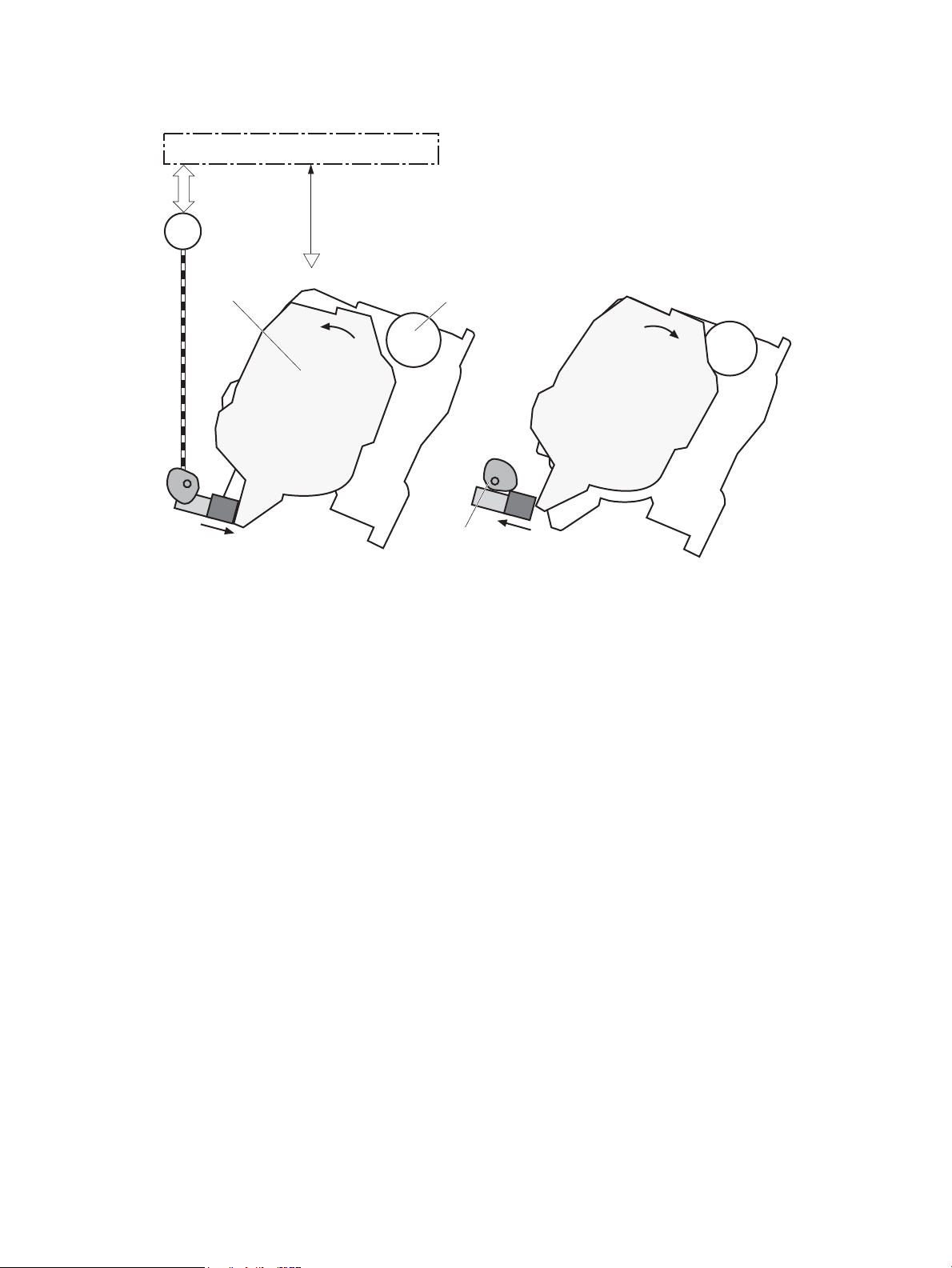
Figure 1-25 Developer roller engagement and disengagement control
Developing unit is disengaged
Developing
disengagement
motor
Photosensitive drum
Developing unit
Developing disengagement cam
SR4
Developing home position sensor
DC controller
M6
Developing unit is engaged
The developer roller engagement and disengagement control operates as follows: When the printer is turned
on and when each print job is completed, all four of the developing units are disengaged from the
photosensitive drums.
●
The drive of the developer disengagement motor rotates the developer disengagement cam.
●
As the cam rotates, the developing unit engages with or separates from the photosensitive drum.
When the print mode is full color, the developing units engage with the drums. When the print mode is blackonly, only the black developing unit engages with the drum.
The DC controller determines a developer disengagement motor failure and noties the formatter when it
does not detect a specied signal from the developer disengagement sensor during the developing unit
engagement and disengagement operation.
Cartridge Authentication Technology (CAT)
CAT supports two features for managing toner cartridges.
●
The authentication feature allows customers to specify the use of only genuine HP toner cartridges in
the printer.
●
The anti-theft feature enables locking a cartridge to a specic printer or eet of printers.
ENWW Engine laser/scanner system 43
Page 72

Authentication
The genuine HP authentication feature allows a customer to specify that only genuine HP supplies can be
used in a printer. If a non-HP or used supply is installed, the printer will not print. This feature is disabled by
default, and can be enabled or disabled from the control panel or the Embedded Web Server (EWS).
If a genuine HP toner cartridge from another printer is moved to a printer with this feature enabled, the toner
cartridge will authenticate and print, unless the toner cartridge has passed the low state. If the toner
cartridge has passed the low state, an Unauthorized Cartridge message displays on the control panel.
If a non-HP toner cartridge is used in a printer with this feature enabled, the message Unauthorized
Cartridge
NOTE: If a customer suspects they have a counterfeit cartridge, they should report it by going to
www.hp.com/go/anticounterfeit and selecting Report now.
Anti-theft
The toner cartridge anti-theft feature allows a customer to congure the printer to automatically lock
genuine HP toner cartridges to a specic printer or eet of printers when they are installed. A locked toner
cartridge will only work in the specied printer or eet of printers. This feature prevents toner cartridges from
being stolen and used in another printer, or from being moved from an authorized printer to an unauthorized
printer. This feature is disabled by default, and can be enabled or disabled from the control panel, the
Embedded Web Server (EWS), or Web Jetadmin.
When the anti-theft feature is enabled, the toner cartridge in a printer will only work in the specied printer or
eet of printers. If a locked toner cartridge is moved to another printer, the cartridge will not print and the
message Protected Cartridge appears on the control-panel display.
appears on the control-panel display.
NOTE: When a toner cartridge is locked to a specic printer or eet of printers, it cannot be unlocked. This is
a permanent operation.
44 Chapter 1 Theory of operation ENWW
Page 73

Intermediate transfer belt (ITB) unit
ITB cleaner
ITB
Drum motor 3
M3
SR5
SL1
M4
Toner collection unit
Toner collection unit full
sensor
Fuser motor
Primary transfer roller
disengagement solenoid
ITB drive roller
Primary transfer roller
DC controller
ITB cleaner
ITB
Drum motor
3
R
5
L
1
4
Toner collection uni
t
Toner collection unit full
r motor
Primary transfer roller
disengagement solenoi
d
ITB drive roller
Primary transfer roller
DC controller
The ITB unit accepts the toner images from the photosensitive drums and transfers the completed image to
the paper. The ITB unit has the following main components:
●
Intermediate transfer belt (ITB)
●
ITB-drive roller
●
Primary-transfer roller
●
ITB cleaner
Drum motor 3 drives the ITB drive roller, which rotates the ITB. The motion of the ITB causes the primary
transfer rollers to rotate. The ITB cleaner cleans the ITB surface.
Figure 1-26 ITB unit
Primary-transfer roller engagement and disengagement control
ENWW Engine laser/scanner system 45
Depending on the requirements of the print job, the primary-transfer rollers engage with the ITB so it can
receive toner from the photosensitive drums. The primary-transfer rollers have three engagement states.
1-16 Primary-transfer roller engagement states
Table
All rollers disengaged The ITB is disengaged from all the four photosensitive drums. This state is the home
All rollers engaged The ITB is engaged with all four photosensitive drums. This is the state for full-color
Black roller engaged The ITB is engaged with only the black photosensitive drum. This is the state for black-
position for the ITB unit.
printing.
only printing.
Page 74

Figure 1-27 Three states of primary-transfer roller engagement and disengagement
Four colors are disengaged
Four colors are engaged
Only black is engaged
Y
M
C
K
Y
M
C
K
Y
M
C
K
Y
M
C
K
Y
M
C
K
Y
M
C
K
Fuser motor
FUSER MOTOR CONTROL
M4
SR5
The primary-transfer-roller disengagement motor rotates or reverses to place the primary-transfer-roller
disengagement cam into one of three positions. The cam causes the transfer-roller slide plate to move to the
right or left. This movement causes the primary-transfer rollers to move up to engage the ITB with the
photosensitive drum or down to disengage it.
The DC controller expects to receive a signal from the ITB home-position sensor when the primary-transfer
roller engages or disengages. If the DC controller does not receive this signal, but detects that the primarytransfer-roller disengagement motor is rotating, the DC controller determines that the primary-transferdisengagement mechanism has failed, and noties the formatter.
46 Chapter 1 Theory of operation ENWW
Page 75

ITB unit detection
The DC controller monitors several signals from the ITB unit to detect status.
ITB unit life detection The DC controller detects whether the ITB unit is new by monitoring the new ITB
ITB unit presence detection The DC controller detects the presence of an ITB unit by monitoring the primary-
unit sensor. The DC controller determines the ITB unit is at end of life and noties
the formatter when a specied number of pages are printed after the ITB unit is
replaced. If swapping ITB units between two printers for troubleshooting
purposes, be sure to return the ITB units to their original printers to maintain the
correct life count.
NOTE: When installing a new ITB, refer to the instructions for resetting the ITB
life counter in the installation guide provided with the replacement part.
transfer roller disengagement sensor. The DC controller turns on the primarytransfer disengagement solenoid for specied times during an initial rotation
period when the following events occur:
●
The printer is turned on
●
The printer exits sleep mode
●
The door is closed
The DC controller determines the absences of an ITB unit and noties the
formatter when it does not detect a specied signal from the new primarytransfer roller disengagement sensor.
ENWW Engine laser/scanner system 47
Page 76

ITB cleaning mechanism
The cleaning blade in the ITB cleaner scrapes the residual toner o the ITB surface and deposits the residual
toner into the toner collection unit. The residual toner feed screw deposits the residual toner to the residual
toner feed unit. The ITB motor and the residual toner feed motor drive the screw. The residual toner that
cannot be removed by the cleaning blade is charged by the ITB cleaning brush, and then transferred from the
ITB surface to the photosensitive drum by the primary transfer (T1) roller. The DC controller detects whether
the toner collection unit is full by using the toner collection unit full sensor, and then noties the formatter.
Figure 1-28 ITB cleaning process
Secondary transfer roller functions
The secondary transfer roller transfers the image from the ITB onto the paper.
The printer has the following secondary transfer roller functions.
Table
1-17 Secondary transfer roller functions
Function Supported feature
Secondary transfer roller cleaning mechanism Yes
Secondary transfer roller presence detection No
Secondary transfer roller life detection No
Secondary transfer roller alienation control Yes
48 Chapter 1 Theory of operation ENWW
Page 77

Calibration
The printer calibrates itself to maintain proper print quality. The calibration corrects color-misregistration and
color-density variation due to environmental changes or internal variation in the printer.
The printer has the following calibration functions.
Table 1-18 Calibration functions
Function Supported feature
Color-plane registration correction control Yes
Environment correction control Yes
Image density control (DMAX) Yes
Image halftone control (DHALF) Yes
Registration density sensor failure detection Yes
Color sensor control No
Gray axis control (GAS) No
Environment sensor failure detection Yes
ENWW Engine laser/scanner system 49
Page 78

Pickup, feed, and delivery system
Simplex paper path
Fuser-and-delivery block
Pickup-and-feed block
Duplex paper path
Duplex block
The DC controller controls the pickup, feed, and delivery system according to commands from the formatter.
The pickup, feed, and delivery system uses a series of rollers to move the paper through the printer.
The pickup, feed, and delivery system consists of the following three functional blocks. The DC controller
controls each block to pick up, feed and deliver the paper.
●
Pickup-and-feed-block: Controls the movement of the paper from each pickup source to the fuser inlet
●
Fuser-and-delivery-block: Controls the movement of the paper from the fuser to the delivery
destination
●
Duplex block: Controls the movement of the paper from the duplex switchback unit to the duplex repickup unit (M552dn, M553dn, M553x, and M577 only)
Figure 1-29 Pickup, feed, and delivery system
50 Chapter 1 Theory of operation ENWW
Page 79

Photo sensors and switches
SR8
SR6 (SR6N)
SR13 (SR13N)
SR14 (SR14N)
SR12
SR9
PS1
SE1
SR10
SW5
The following gure shows the sensors and switches for the pickup, feed, and delivery system.
Figure 1-30 Photo sensors and switches
Table 1-19 Photo sensors and switches
Abbreviation Component Replacement part number
PS1 Loop sensor Fuser
SE1 Media sensor Registration assembly
SR6 Top-of-page (TOP) sensor (M552dn, M553dn, M553x,
and M577 only)
●
B5L35-67901 (110V)
●
B5L36-67901 (220V)
●
RM2-0093-000CN (M553n)
●
RM2-0018-000CN (M552dn, M553dn, M553x, M577)
Registration assembly (RM2-0018-000CN)
SR6N Top-of-page (TOP) sensor (M553n only) Registration assembly (RM2-0093-000CN)
SR8 Tray 1 media-out sensor Right door assembly (RM2-0019-000CN)
ENWW Pickup, feed, and delivery system 51
Page 80

Table 1-19 Photo sensors and switches (continued)
Abbreviation Component Replacement part number
SR9 Fuser delivery sensor Fuser
●
B5L35-67901 (110V)
●
B5L36-67901 (220V)
SR10 Output bin media-full sensor Paper delivery assembly
●
RM2-0092-000CN (M553n)
●
RM2-0016-000CN (M552dn, M553dn, M553x, M577)
SR11 Fuser pressure release sensor Part not available
SR12 Tray 2 media-out sensor Paper pickup assembly (RM2-0017-000CN)
SR13 Media width sensor, front (M552dn, M553dn, M553x
and M577 only)
SR13N Media width sensor, front (M553n only) Registration assembly (RM2-0093-000CN)
SR14 Media width sensor, rear (M552dn, M553dn, M553x and
M577 only)
SR14N Media width sensor, rear (M553n only) Registration assembly (RM2-0093-000CN)
SW5 Tray 2 detection switch Part not available
Registration assembly (RM2-0018-000CN)
Registration assembly (RM2-0018-000CN)
52 Chapter 1 Theory of operation ENWW
Page 81

Motors, clutches, and solenoids
M8
SL3
M4
M8
CL2M3SL2CL1
M5
The following gure shows the motors, clutches, and solenoids for the pickup, feed, and delivery system.
Figure 1-31 Motors, clutches, and solenoids
Table 1-20 Motors, clutches, and solenoids
Abbreviation Component Replacement part number
M3 Drum motor 3 Drum motor assembly (RM2-0078-000CN)
M4 Fuser motor Fuser motor assembly (RM2-0077-000CN)
M5 Pickup motor Paper pickup drive assembly (RM2-0008-000CN)
M6 Developer disengagement motor Stepping motor (RK2-6027-000CN)
M7 Scanner motor Laser scanner assembly (RM2-0100-000CN)
M8 Duplex reverse motor (M552dn, M553dn, M553x, and
M577 only)
Duplexing drive assembly (RM2-0006-000CN)
ENWW Pickup, feed, and delivery system 53
Page 82

Table 1-20 Motors, clutches, and solenoids (continued)
Abbreviation Component Replacement part number
CL1 Tray 2 pickup clutch Lifter drive assembly (RM2-0010-000CN)
CL2 Duplex re-pickup clutch (M552dn, M553dn, M553x, and
M577 only)
SL1 Primary transfer roller alienation solenoid Fuser drive assembly
SL2 Tray 1 pickup solenoid Right door assembly (RM2-0019-000CN)
SL3 Duplex reverse solenoid (M552dn, M553dn, M553x, and
M577 only)
Tray 1 (multipurpose)/Tray 2 (base printer)
Moving paper from Tray 1 and Tray 2 involves the interaction of multiple components within the printer. The
following sections describe these processes.
Tray 1 paper pickup and feed
The printer picks up one sheet of paper from Tray 1.
Duplexing drive assembly (RM2-0006-000CN)
●
RM2-0091-000CN (M553n)
●
RM2-0009-000CN (M552dn, M553dn, M553x,
M577)
Duplexing drive assembly (RM2-0006-000CN)
Following are the sequence of steps for the Tray 1 pickup operation.
NOTE: Tray 1 and Tray 2 are optimal for paper pickup when using special paper or media other than 20 lb
plain paper. For Tray 1, the printer increases the number of attempts to pick up a page, which increases the
reliability of successfully picking the page from the tray and decreases the possibility of a mis-pick jam.
HP recommends using Tray 1 or Tray 2 if the printer is experiencing excessive or reoccurring jams from trays
other than Tray 1 and Tray 2, or for print jobs that require media other than 20 lb plain paper.
1. The pickup motor reverses when a print command is received from the formatter.
2. When the DC controller turns on the Tray 1 pickup solenoid, the Tray 1 pickup roller rotates and the
lifting plate lifts.
3. As the lifting plate rises, the paper is picked up.
4. The Tray 1 separation pad removes any multiply-fed sheets, and one sheet is fed into the printer.
The Tray 1 media-out sensor (SR8) detects whether paper is present in Tray 1.
54 Chapter 1 Theory of operation ENWW
Page 83

Figure 1-32 Tray 1 pickup mechanism
M5
SR8
SL2
Tray 1 pickup solenoid
Tray 1 pickup roller
Tray 1 separation pad
Tray 2 paper presence detection
The Tray 2 media-out sensor (SR12) detects the presence of paper in Tray 2.
The DC controller noties the formatter when the Tray 2 media-out sensor detects that paper is absent.
Tray 2 lift operation
The printer keeps the paper stack surface at the correct pickup position. The Tray 2 lift-up operation is
performed under the following conditions:
●
The printer is turned on
●
Tray 2 is installed
●
The paper stack surface in Tray 2 lowers
The operational sequence of the Tray 2 lift operation is as follows:
ENWW Pickup, feed, and delivery system 55
Page 84

1. The pickup motor (M5) rotates and the lifter moves up. Note that this printer uses the pickup motor
rather than a dedicated lifter motor.
2. When the Tray 2 media stack surface sensor 2 detects the stack surface of media, the lifter motor stops.
3. The lifter motor rotates again to lift the lifter when the Tray 2 media stack surface sensor 1 detects the
stack surface and then lowers during printing.
When a Tray 2 media stack surface sensors does not detect the stack surface within a specied time period
after the lifter motor starts rotating, the DC controller determines a lifter motor failure and noties the
formatter.
Tray 2 paper pickup
Following are the sequence of steps for the Tray 2 pickup operation.
NOTE: Tray 1 and Tray 2 are optimal for paper pickup when using special paper or media other than 20 lb
plain paper. For Tray 1, the printer increases the number of attempts to pick up a page, which increases the
reliability of successfully picking the page from the tray and decreases the possibility of a mis-pick jam.
HP recommends using Tray 1 or Tray 2 if the printer is experiencing excessive or reoccurring jams from trays
other than Tray 1 and Tray 2, or for print jobs that require media other than 20 lb plain paper.
1. The printer is turned on or Tray 2 is inserted.
2. The tray lift-up operation raises the lifting plate so paper can be picked up.
3. The pickup motor rotates when a print command is received from the formatter.
4. The Tray 2 pickup roller and Tray 2 feed roller rotate.
5. The Tray 2 pickup solenoid turns on at a specied time.
6. The Tray 2 pickup cam rotates.
7. As the pickup arm lowers, the Tray 2 pickup roller touches the surface of the paper stack.
8. One sheet of paper feeds into the printer.
Tray 2 multiple-feed prevention
The printer uses a separation roller method to prevent multiple sheets of print media from entering the paper
path.
The separation roller overruns if just one sheet of paper is picked. If two or more sheets are picked, only the
top sheet will be fed to registration and the multiply-fed sheets will be held at the pickup location by the
separation roller. This printer does not have an actively-driven separation roller.
56 Chapter 1 Theory of operation ENWW
Page 85

Figure 1-33 Tray 2 multiple-feed prevention
Tray 2 separation roller
follows the Tray 2 feed roller
Driving force from
the pickup motor
Normal feed
Multiple feed
Paper
Tray 2 pickup roller
Tray 2 separation roller
Tray 1 feed roller
Tray 2 separation roller
llows the Tray 2 feed roller
Driving force from
the pickup motor
Normal
feed
ultiple fee
d
Paper
Tray 2 pickup roller
Tray 2 separation roller
Tray 1 feed roller
Tray 2 presence detection
The Tray 2 presence sensor is in the lifter drive unit. The sensor detects the tray-presence sensor ag and
determines whether the cassette is installed correctly.
Tray 2 skew feed prevention
The printer can straighten the paper without slowing the feed operation.
1. The leading edge of paper strikes the registration shutter, and the leading edge is aligned with the
shutter.
2. As the feed rollers keep pushing the paper, the paper warps.
3. When the force is great enough, the registration shutter rotates, and the paper passes through
straightened.
ENWW Pickup, feed, and delivery system 57
Page 86

Figure 1-34 Skew-feed prevention
Registration shutter
Paper
Registration shutter
Paper
Tray 2 media type detection
The printer selects the optimal print mode based upon the media type detected by the media sensor. The
media sensor consists of an optical sensor, which detects the surface texture of the paper, and an ultrasonic
sensor, which measures the thickness of the paper.
Following are the print modes detected by the printer:
●
Normal
●
Heavy media 1
●
Heavy media 2
●
Heavy media 3
58 Chapter 1 Theory of operation ENWW
Page 87

●
Optical sensor
Ultrasonic sensor
Registration unit
Light media
●
Glossy media 1
●
Glossy media 2
●
Glossy media 3
●
LBP_OHT
The DC controller determines a media sensor error and reports it to the formatter when the value detected by
the media sensor is out of a specied range of values.
Figure 1-35 Media sensors
Feed speed control
The DC controller adjusts the feed speed to improve the print quality depending on the paper type. The paper
is fed at a specied speed according to the print mode designated by the formatter.
Table
1-21 Print mode and feed speed
Print mode
Normal 1/1 Yes
Heavy media 1 Pro No
Heavy media 2 1/2 Yes
Heavy media 3 1/3 Yes
Light media 1 1/1 Yes
Light media 2 1/1 Yes
Light media 3 1/3 Yes
Feed speed
ENWW Pickup, feed, and delivery system 59
1
Media sensor detection
Page 88

Table 1-21 Print mode and feed speed (continued)
Print mode
Glossy media 1 1/3 Yes
Glossy media 2 1/3 Yes
Glossy media 3 1/3 Yes
Glossy lm 1/3 Yes
Envelope 1 1/2 No
OHT 1/3 Yes
Label 1/2 No
Designated media 1 1/2 No
Designated media 2 1/3 No
Designated media 3 Pro No
1
Speed for both full color and black and white pages
1/1 speed = 210 mm/s
Pro speed = 174 mm/s
1/2 speed = 105 mm/s
1/3 speed = 70 mm/s
Feed speed
1
Media sensor detection
Duplexing unit (M552dn, M553dn, M553x, and M577 only)
The duplexing unit reverses the paper and feeds it through the paper path to print the second side.
Duplexing reverse and duplex feed control
The duplex reverse control reverses the paper after the rst side is printed and feeds it to the duplex repickup position to print the second side of the page.
1. At a specied time after the rst side of a page is printed, the duplex reverse motor rotates, and the
duplex reverse solenoid is turned on.
2. The duplex apper moves, and the paper feeds to the duplex reverse unit.
3. After a specied period of time, the duplex reverse motor reverses, and the paper feeds to the duplex
feed unit.
4. The duplex reverse motor and the pickup motor move the paper to the duplex re-pickup position.
5. The duplex reverse motor and the duplex feed clutch stop, and the paper feed operation pauses.
6. After a specied period of time, the duplex reverse motor rotates, and the duplex feed clutch is turned
on. The paper is then picked up again.
Jam detection/prevention
The printer uses the following sensors to detect the paper as it moves through the paper path and to report
to the DC controller if the paper has jammed.
●
Top of page (TOP) sensor (SR6/SR6N)
●
Media width sensor (front, SR13/SR13N)
60 Chapter 1 Theory of operation ENWW
Page 89

●
SR6(SR6N)
SR13(SR13N)
SR14(SR14N)
SR9
PS1
SR10
SR21
Media width sensor (rear, SR14/SR14N)
●
Loop sensor (PS1)
●
Fuser delivery sensor (SR9)
●
Output bin media-full sensor (SR10)
●
1x550 sheet paper feeder media feed sensor (SR21)
Figure 1-36 Jam detection sensors
The printer determines that a jam has occurred if one of these sensors detects paper at an inappropriate
time. The DC controller stops the print operation and noties the formatter.
1-22 Jams that the printer detects
Table
Jam Description
Media input delay jam 1 Media did not reach the registration sensor in time.
Media input delay jam 2 Media did not reach the source tray feed sensor in time.
Media input delay jam 3 Media did not reach the tray 3 feed sensor in time.
ENWW Pickup, feed, and delivery system 61
Page 90

Table 1-22 Jams that the printer detects (continued)
Jam Description
Duplex re-feed jam 1 Media did not reach the registration sensor in time.
Media input stay jam 1 Media remained at the registration sensor longer than legal-sized media should remain.
Fuser delivery delay jam 1 Media did not reach the fuser output sensor in time.
Fuser delivery stay jam 1 Media stayed at fuser output sensor longer than it should stay. Media is in duplex path.
Fuser delivery stay jam 2 Media stayed at fuser output sensor longer than it should stay. Media is in simplex path.
Wrap jam 1 Media is rst detected at fuser output sensor and then disappeared from the sensor before it should
have disappeared.
Door open jam A door is open while paper is moving through the printer.
Residual Media in paper path
jam 1
Fuser wrapping jam detection
The printer includes controls for detecting when a jam occurs causing the paper to wrap around the fuser
roller.
Loop control
The loop control stabilizes the paper feed operation before the paper enters the fuser. If the pressure roller
rotates slower than the secondary transfer roller, the paper loop increases and an image defect or paper
crease occurs. If the pressure roller rotates faster than the secondary transfer roller, the paper loop decreases
and a vertical scanning magnication failure occurs because the pressure roller pulls the paper.
To prevent these problems, the loop sensor detects the paper loop before the paper enters the fuser. The DC
controller adjusts the rotational speed of the fuser motor according to the output signals from the loop
sensor and maintains the paper loop. The DC controller slows the fuser motor when the sensor is o and
speeds up the motor when the sensor is on.
Media detected in the paper path.
62 Chapter 1 Theory of operation ENWW
Page 91
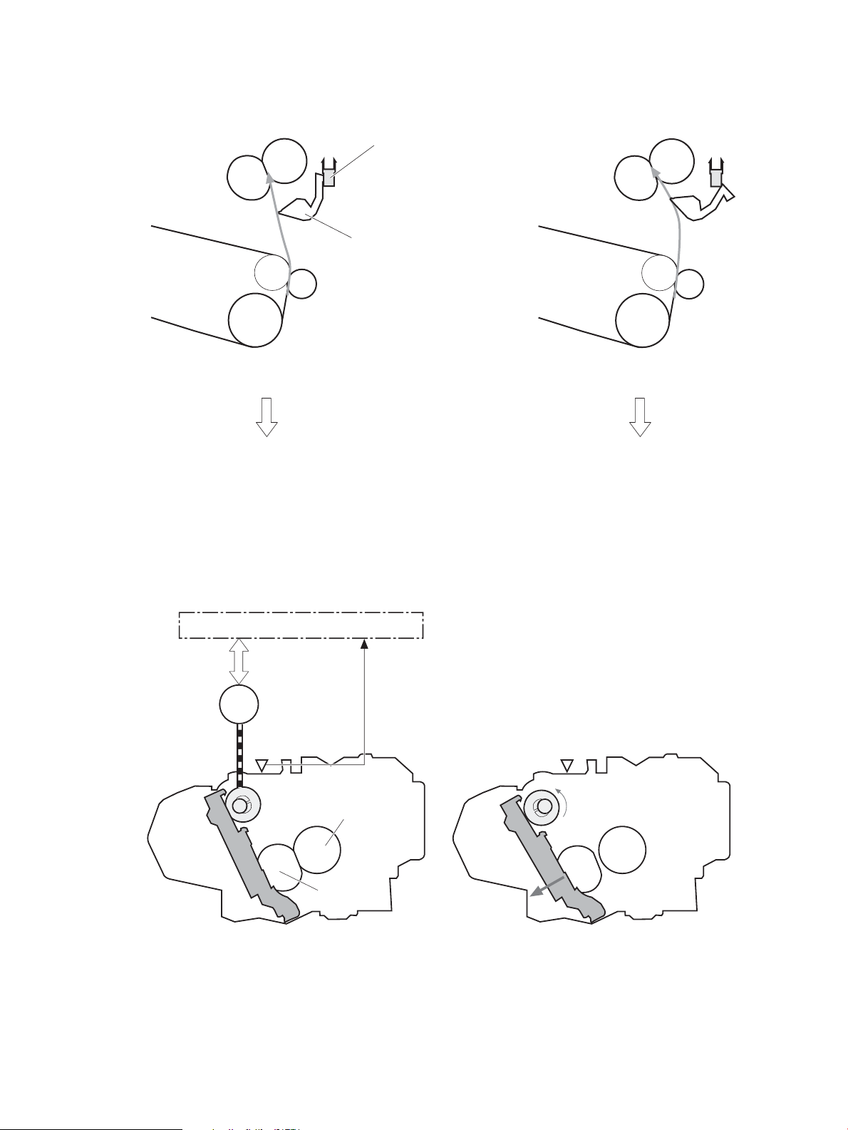
Figure 1-37 Loop control mechanism
The pressure roller rotates faster
than the secondary transfer roller
Loop sensor: OFF
ITB
Loop sensor
Secondary transfer rollerr
Pressure roller
Sensor flag
Loop sensor: ON
The pressure roller rotates slower
than the secondary transfer roller
SR11 SR11
M4
Pressure roller
DC controller
Fuser pressure release cam
Fuser motor
Pressurized Depressurized
Fuser sleeve
Pressure roller pressurization and depressurization control
To prevent excessive wear on the pressure roller and help with jam-clearing procedures, the pressure roller
pressurizes only during printing and standby. The DC controller reverses the fuser motor. The fuser motor
rotates the fuser pressure-release cam.
Figure 1-38 Pressure roller pressurization control
The pressure roller depressurizes under the following conditions:
ENWW Pickup, feed, and delivery system 63
Page 92

●
The printer is turned o
●
Any failure occurs
●
During power-save mode
●
A paper jam is detected
If the DC controller does not sense the fuser pressure-release sensor for a specied period after it reverses
the fuser motor, it noties the formatter that a fuser pressure-release mechanism failure has occurred.
64 Chapter 1 Theory of operation ENWW
Page 93

Input accessories
NOTE: An optional 550-sheet paper feeder is available for this printer. The printer supports up to three of
these paper feeders at a time.
Trays 3-5
The 550-sheet paper feeder is installed under the printer. It picks up paper and feeds it into the printer.
Figure 1-39 550-sheet paper feeder
Trays 3-5 driver PCA
The paper feeder controller controls the operational sequence of the paper feeder.
ENWW Input accessories 65
Page 94

Figure 1-40 Tray 3-5 driver PCA
+24V
+3.3V
DC controller
Paper feeder controller
Motor
Photointerruptor
Clutch
Switch
550-sheet paper feeder
Trays 3-5 motor control
The 550-sheet paper feeder has one motor for lifting the tray and feeding paper.
Table 1-23 Trays 3-5 motor control
Component Drives Failure
detection
Trays 3-5 electrical components
M20 Feed motor (550-sheet paper
feeder)
Tray pickup roller (B5L24-67904)
Tray feed roller (B5L24-67904)
Paper feed assembly (RM2-5145-000CN)
Lifter drive assembly (RM2-5149-000CN)
No
The paper feeder contains several motors, solenoids, sensors, and switches, as described in the following
table.
Table
1-24 Tray 3-5 electrical components
Component type Abbreviation Component name Replacement part number
Motor M20 Feed motor (550-sheet paper feeder) Paper feed assembly
(RM2-5145-000CN)
Clutch CL20 Tray pick up clutch (550-sheet paper
feeder)
Switches SW20 Right door switch (550-sheet paper
feeder)
Sensors SR20 Tray media-out sensor (550-sheet
SW21 Tray detection switch (550-sheet paper
feeder)
paper feeder)
Lifter drive assembly
(RM2-5149-000CN)
Right door (RM2-5146-000CN)
Switch button (WC2-5806-000CN)
Paper pick up assembly
(RM2-5154-000CN)
66 Chapter 1 Theory of operation ENWW
Page 95

Table 1-24 Tray 3-5 electrical components (continued)
M20
CL20
SR21
SW21
SR20
Component type Abbreviation Component name Replacement part number
Trays 3-5 paper pickup
The 550-sheet paper feeder picks up one sheet from the paper-feeder tray and feeds it to the printer.
Figure 1-41 Paper pickup and feed operation (550-sheet paper feeder)
SR21 Feed sensor (550-sheet paper feeder) Paper feed assembly
(RM2-5145-000CN)
Table 1-25 Pickup feed components (1x550-sheet paper feeder)
Abbreviation Component Replacement part number
M20 Feed motor (550-sheet paper feeder) Paper feed assembly (RM2-5145-000CN)
CL20 Tray pickup clutch (550-sheet paper feeder) Part not available
SR20 Tray media-out sensor (550-sheet paper feeder) Paper pick up assembly (RM2-5154-000CN)
SR21 Feed sensor (550-sheet paper feeder) Paper feed assembly (RM2-5145-000CN)
SW21 Tray detection switch (550-sheet paper feeder) Switch button (WC2-5806-000CN)
Trays 3-5 multiple feed prevention
The multiple-feed prevention for the 550-sheet paper feeder is operated in the same way as that of the
printer base.
Trays 3-5 tray presence detection
The presence detection for the 550-sheet paper feeder is the same way as that of the printer base.
ENWW Input accessories 67
Page 96

Trays 3-5 tray lift operation
The 550-sheet paper feeder keeps the paper stack surface at the correct pickup position. The tray lift
operation occurs under the following conditions:
●
The printer is turned on.
●
The tray is inserted.
●
The paper stack surface of the tray lowers.
The sequence occurs as follows:
1. The feeder tray-lifting motor rotates and the lifter moves up.
2. When the paper-feeder media-stack-surface sensor detects the stack surface of the paper, the lifting
motor stops.
3. The lifting motor rotates again to lift the lifter when the paper-feeder media-stack-surface sensor
detects the stack surface, and then lowers during printing.
If a tray media-stack-surface sensor does not detect a stack surface within a specied period after the lifting
motor starts rotating, the paper feeder driver determines that the lifting motor has failed and noties the
formatter through the DC controller.
The paper-feeder driver noties the formatter if either of the paper-feeder media-stack-surface sensors fails
to detect the stack surface within a specied period from when a lift-up operation starts.
68 Chapter 1 Theory of operation ENWW
Page 97

Trays 3-5 jam detection
SR21
SW20
The 550-sheet paper feeder uses the feed sensor (SR21) and right door switch (SW20) to detect the presence
of paper and to check whether paper has jammed.
Figure 1-42 Jam detection (1x550-sheet paper feeder)
The 550-sheet paper feeder detects the following jams:
●
Media input delay jam 1 (550-sheet paper feeder): Paper did not reach the registration sensor in time.
●
Media input delay jam 2 (550-sheet paper feeder): Paper did not reach the source tray feed sensor in
time.
●
Media input delay jam 3 (550-sheet paper feeder): Paper did not reach the tray 3 feed sensor in time.
●
Pickup stationary jam (550-sheet paper feeder): The feed sensor does not detect the trailing edge of
paper within a specied time after the sensor detects the leading edge.
●
Residual paper jam (550-sheet paper feeder): The feed sensor detects the presence of paper for a
specied time during an automatic delivery operation.
●
Right door open jam (550-sheet paper feeder): The right door open is detected during a paper feed
operation.
ENWW Input accessories 69
Page 98

Scanning and image capture system (M577)
NOTE: This section is for the M577 printer only.
The scanner is a carriage-type platen scanner which includes the frame, glass, scan module, and a scan
control board (SCB). The scanner has a sensor to detect legal-sized media and a switch to indicate when the
document feeder is opened.
The document feeder and control panel are attached to the scanner. If the scanner fails, it can be replaced as
a whole unit. The scanner replacement part does not include the document feeder, control panel, or SCB.
70 Chapter 1 Theory of operation ENWW
Page 99

Document feeder system (M577)
NOTE: This section is for the M577 printer only.
Document feed system
This section describes the following:
●
Sensors in the document feeder
●
Document feeder paper path
●
Simplex single-pass scanning
●
Electronic duplexing (e-duplex) single-pass scanning
●
Deskew operation
●
Document feeder hinges
The printer supports single-pass electronic duplexing (e-duplex) copy jobs. Two separate scan modules scan
the front-side and back-side of an e-duplex copy job page in a single pass through the document feeder.
For the M577c/z models, the document feeder supports a smart background, which auto-crops and adjusts
the image extents.
Sensors in the document feeder
The document feeder contains the following sensors:
●
ADF paper present sensor: Detects whether a document is present in the document feeder. If paper is
present in the document feeder when copies are made, the printer scans the document using the
document feeder. If no paper is present when copies are made, the printer scans the document using
the scanner glass.
●
ADF Y (length) sensor: Detects whether a legal-size original is present in the document feeder.
●
ADF jam cover sensor: Detects whether the document feeder cover is open or closed.
●
ADF paper path deskew sensor: Detects the top of the page as it enters the deskew rollers.
●
ADF paper path pick success sensor: Detects a successful one page feed from the document feeder
tray.
NOTE: This sensor uses ultrasonic sound to detect a multi-page paper feed.
●
Paper path sensor 1: Detects the top of the page as it approaches the front-side scan module
(document feeder glass).
ENWW Document feeder system (M577) 71
Page 100

Figure 1-43 Document feeder sensors
1
2
5
3
4
Table 1-26 Document feeder sensors
Item Description
1 ADF Y (length) sensor
2 ADF paper present sensor
3 ADF deskew sensor
4 Paper path sensor 1
NOTE: For an e-duplex copy job, this sensor is used to activate the front-side scan module (in the
scanner base) and the front-side background selector (in the document feeder), if needed.
5 ADF jam cover sensor (open the jam access cover and insert a folded piece of paper to activate the ag)
Document feeder paper path
Figure 1-44 Document feeder paper path
Table
1-27 Document feeder paper path
Item Description Item Description
1 Input tray 7 Front-side scan module
NOTE: This scan module (document feeder glass) is
located in the scanner base.
2 Pre-pick roller 8 Back-side scan module
72 Chapter 1 Theory of operation ENWW
 Loading...