

Page 1
HPE FlexFabric 12916E LSXM116XFAN Fan Tray User Manual-6PW101
BOM:3101A0HW Part number:5998-6757R
Overview
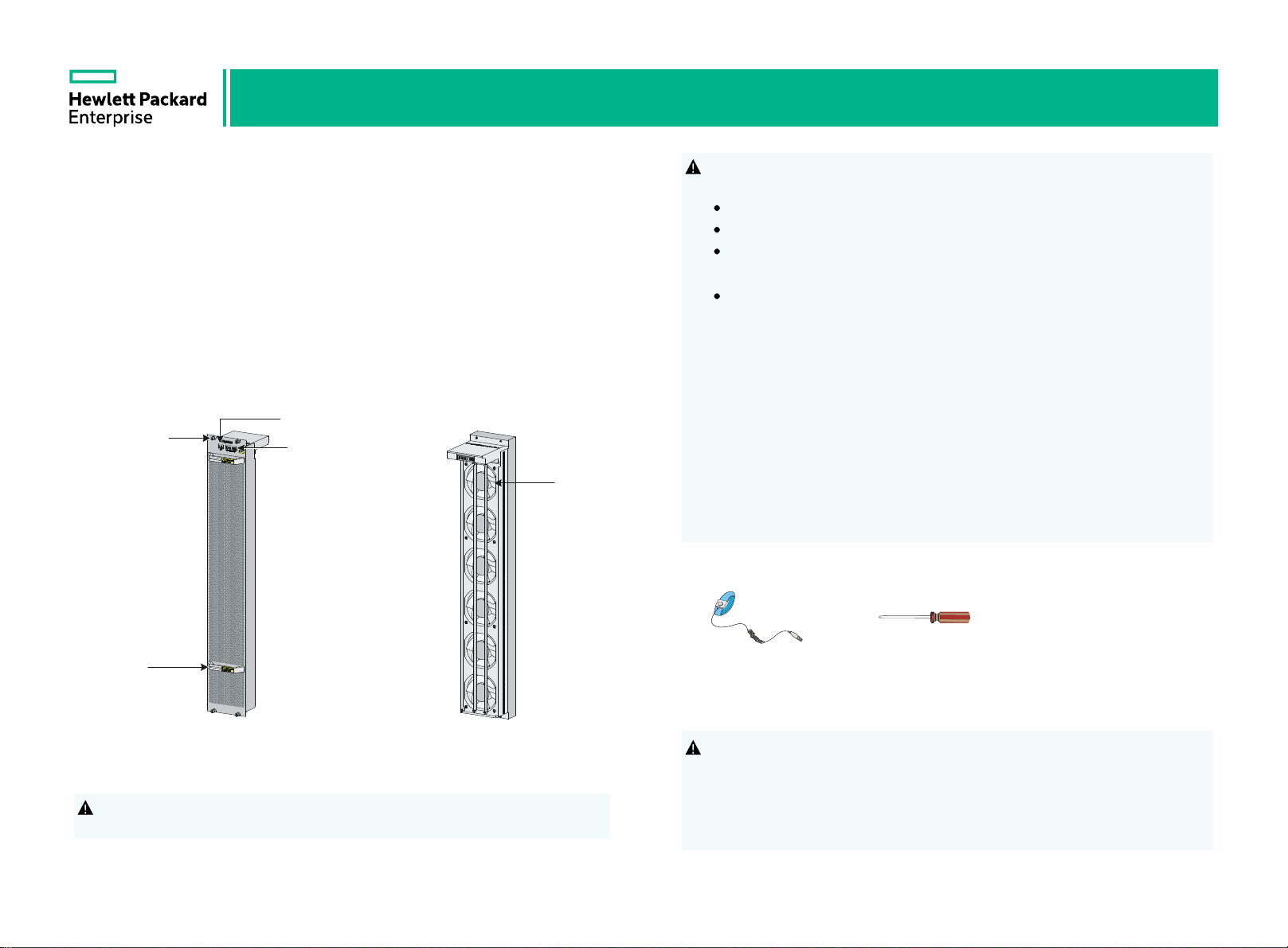
The LSXM116XFAN fan tray (JH106A) contains six fans. It applies to the
12916E switch. The 12916E switch has two fan tray slots: FAN1 and FAN2.
One fan tray is sufficient for heat dissipation of the switch. As a best practice,
install two fan trays on the switch for redundancy and noise reduction. When
the fan tray is operating, ambient air flows in through the air vents in the MPU
and LPU/interface module adapter panels, circulates through the switching
fabric module section, and flows out through the air vents in the fan tray with
the heat carried from the MPU, LPU, and switching fabric module sections.
Fan tray status LED
Captive screw
Switching fabric
module status
LED
Fan
The fan tray is hot swappable. Follow these guidelines when you replace the
!
fan tray on an operating 12916E switch:
Ensure electricity safety.
Replace a fan tray only when the other fan tray is operating correctly.
To prevent dust from entering the chassis, keep the failed fan tray in
position before the replacement.
When you hot-swap a fan tray, the remaining fan tray automatically
increases the fan rotation speed and makes louder noise. Take protection
measures such as wearing an earmuff or earplug. In addition, make good
preparation before the hot-swapping to minimize the operation time.
Before you install or replace a switching fabric module on an operating
12916E switch, first remove the fan tray. Install the fan tray immediately after
you finishing installing or replacing the switching fabric module.
For good ventilation, install filler panels in empty switching fabric module slots.
Long-time exposure to strong air flow might cause discomfort. To avoid this
hazard, do not stand close to the air outlet vents while the switch is operating.
If you must be next to the switch on the air outlet vent side for an extended
period, avoid the air flow or take other protective measures.
Tools required
Handle
Panel side view Fan side view
To avoid device damage and bodily injury, use two people to install or remove
!
the fan tray.
ESD-preventive
wrist strap
Phillips
screwdriver
Installing a fan tray
Before you install a fan tray, first install the switching fabric modules or filler
!
panels in the switching fabric module slots.
The procedures are similar for installing a fan tray in FAN1 slot and FAN2 slot.
To install a fan tray in FAN1 slot, align the top and left edges of the fan tray in
the slot. To install a fan tray in FAN2 slot, align the top and right edges of the
fan tray in the slot.
1
2
Page 2
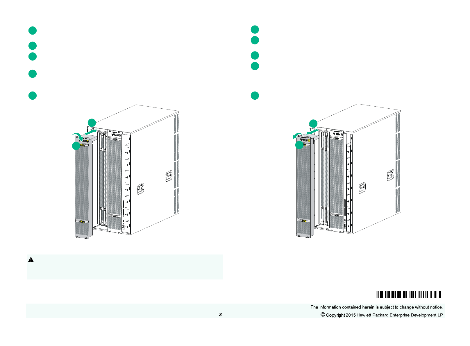
Wear an ESD wrist strap and make sure it makes good skin contact and is
1
reliably grounded.
2
Unpack the fan tray.
Orient the fan tray with the upside up and align the fan tray with the fan tray
3
slot.
Holding the upper fan tray handle with one hand and the lower fan tray
4
handle with the other hand, insert the fan tray into the slot. Keep the fan tray
as straight as possible.
5
Fasten the captive screws on the fan tray.
1
Prepare an anti-static mat.
Wear an ESD wrist strap and make sure it makes good skin contact and is
2
reliably grounded.
3
Loosen the captive screws on the fan tray.
Holding the upper fan tray handle with one hand and the lower fan tray
4
handle with the other hand, pull the fan tray outwards slowly until the fa n tray
is disengaged from the chassis. Remove the fan tray after the fans stop
rotating.
5
Place the fan tray on the anti-static mat.
1
2
Removing a fan tray
When you remove a fan tray, do not touch the rotating fans to avoid getting
!
injured.
Before you replace a switching fabric module, remove the fan tray.
2
1
Documentation
To access documentation and support services, go to the Hewlett Packard
Enterprise Support Center website:
www.hpe.com/support/hpesc
5998-6757R
 Loading...