

Page 1
HPE LSWM124XGT2Q Interface
Module (JH182A) User Guide
Part number: 5998-7152u
▌Introduction
Product code HPE description Alias
JH182A
HPE 5930 24-port 10GBASE-T and
2-port QSFP+ with MACsec Module
Overview
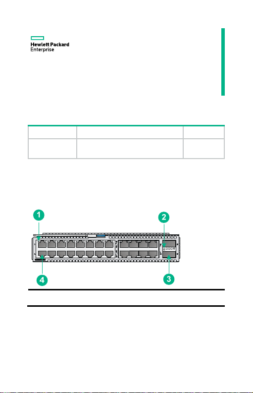
Each LSWM124XGT2Q interface module provides 24 10GBASE-T
ports and two QSFP+ ports.
Figure 1 LSWM124XGT2Q interface module front panel
(1) 10GBASE-T port LED (2) QSFP+ port LED
(3) QSFP+ port (4) 10GBASE-T port
LSWM124X
GT2Q
1
Page 2

1/10GBase-T autosensing Ethernet port
Table 1 1/10GBase-T autosensing Ethernet port specifications
Item Specification
Connector type RJ-45
Port standard
Transmission medium
and max transmission
distance
Compliance standards
1/10 Gbps full duplex, MDI/MDI-X
auto-sensing
• 55 m (180.45 ft) over category-6
unshielded twisted pair cable
• 100 m (328.08 ft) over category-6
shielded twisted pair cable
• 100 m (328.08 ft) over category-6A or
above twisted pair cable
• IEEE 802.3an
• IEEE 802.3ab
QSFP+ ports
The QSFP+ ports on the LSWM124XGT2Q interface module support
the following transceiver modules and cables:
• QSFP+ transceiver modules in Table 2 an
• QSFP+ cables in Ta ble 4.
• QSFP+ t
Table
ports (1)
o SFP+ cables in Table 5.
2 40G QSFP+ transceiver modules available for the QSFP+
d Table 3.
Product
code
JG325B
JG709A
HPE description
HPE X140 40G
QSFP+ MPO SR4
Transceiver
HPE X140 40G
QSFP+ MPO MM
850nm CSR4 300m
Transceiver
Central
wavelength (nm)
850 MPO
850 MPO
2
Connector
Page 3
Product
code
HPE description
Central
wavelength (nm)
Connector
Four lanes:
JG661A
HPE X140 40G
QSFP+ LC LR4 SM
10km 1310nm
Transceiver
• 1271
• 1291
• 1311
LC
• 1331
Table 3 40G QSFP+ transceiver modules available for the QSFP+
ports (2)
Product
code
JG325B
JG709A
JG661A
Cable/fiber
diameter (µm)
Multi-mode,
50/125
Multi-mode,
50/125
Single-mode,
9/125
Modal
bandwidth
(MHz × km)
Max transmission
distance
2000 100 m (328.08 ft)
4700 150 m (492.13 ft)
2000 300 m (984.25 ft)
4700 400 m (1312.34 ft)
N/A 10 km (6.21 miles)
Table 4 40G QSFP+ cables available for the QSFP+ ports
Product
code
JG326A
JG327A
HPE description Cable length Data rate
HPE X240 40G QSFP+
QSFP+ 1m Direct Attach
Copper Cable
HPE X240 40G QSFP+
QSFP+ 3m Direct Attach
Copper Cable
1 m (3.28 ft) 40 Gbps
3 m (9.84 ft) 40 Gbps
3
Page 4

Product
code
JG328A
HPE description Cable length Data rate
HPE X240 40G QSFP+
QSFP+ 5m Direct Attach
Copper Cable
5 m (16.40 ft) 40 Gbps
Table 5 40G QSFP+ to SFP+ cables available for the QSFP+ ports
Product
code
JG329A
JG330A
JG331A
For more information about HPE QSFP+ transceiver modules,
QSFP+ cables, and QSFP+ to SFP+ cables, see HPE
Comware-Based Devices Transceiver Modules User Guide.
HPE description Cable length Data rate
HPE X240 40G QSFP+ to
4x10G SFP+ 1m Direct
Attach Copper Splitter Cable
HPE X240 40G QSFP+ to
4x10G SFP+ 3m Direct
Attach Copper Splitter Cable
HPE X240 40G QSFP+ to
4x10G SFP+ 5m Direct
Attach Copper Splitter Cable
1 m (3.28 ft) 40 Gbps
3 m (9.84 ft) 40 Gbps
5 m (16.40 ft) 40 Gbps
NOTE:
• When you install the interface module on the HPE FlexFabric
5930 4-Slot Switch (JH179A), HPE FlexFabric 5930 4-Slot
TAA Switch (JH188A), and HPE FlexFabric 5940 4-Slot Switch
(JH398A) the 40-GE QSFP+ ports on the interface modules
cannot be split into four 10-GE SFP+ ports.
• As a best practice, use HPE transceiver modules and cables
for the QSFP+ ports. The available transceiver modules and
cables might change over time. For the most recent list of
available transceiver modules and cables, contact Hewlett
Packard Enterprise Support or marketing staff.
4
Page 5

LEDs
Table 6 describes 1/10GBASE-T autosensing Ethernet port
LEDs. Table 7 descri
Table 6 1/10GBase-T autosensing Ethernet port LED description
LED status Description
Steady green The port has a link and is operating at 10 Gbps.
Flashing green The port is sending or receiving data at 10 Gbps.
Steady yellow The port has a link and is operating at 1 Gbps.
Flashing yellow The port is sending or receiving data at 1 Gbps.
Off No link is present on the port.
Table 7 QSFP+ port LED description
LED status Description
Steady green
Flashing green The port is sending or receiving data at 40 Gbps.
Steady yellow
Flashing yellow The port is sending or receiving data at 10 Gbps.
Off
NOTE:
The 10GBASE-T port LEDs and QSFP+ port LEDs are not
affected by the port mode switching button on your switch. For
more information about the port mode switching button, see the
installation guide of the switch.
bes QSFP+ port LEDs.
A transceiver module or cable has been
correctly installed. The port has a link and is
operating at 40 Gbps.
A transceiver module or cable has been
correctly installed. The port has a link and is
operating at 10 Gbps.
No transceiver module or cable has been
installed or no link is present on the port.
5
Page 6

▌Installing and removing the interface module
CAUTION:
• Before you install or remove the interface module, wear an
ESD wrist strap and make sure the strap makes good skin
contact and is reliably grounded.
• To avoid device damage, do not use excessive force when you
install or remove the interface module.
Installing the interface module
Before you install the interface module, remove the filler panel (if any)
from the target slot. Keep the removed filler panel for future use.
To install the interface module:
1. Unpack the interface module.
Figure 2 LSWM124XGT2Q interface module
(1) Ejector lever (2) Latch
2. Press the latch on the interface module to release the ejector
lever.
3. Insert the interface module slowly into the slot along the guide
rails, as shown by callout 1 in Figure 3.
4. Rotate i
nward the ejector lever until the latch locks the ejector
lever in place, as shown by callout 2 in Figure 3.
6
Page 7

Figure 3 Installing the LSWM124XGT2Q interface module
Removing the interface module
CAUTION:
• Before you remove the interface module, remove the cable
from it to avoid cable damage.
• If you are not to install a new interface module,, install a filler
panel in the slot to prevent dust and ensure good ventilation in
the device.
To remove the interface module:
1. Prepare an anti-static bag.
2. Press the latch to release the ejector lever
3. Rotate outward the ejector lever, as shown by callout 1 in Figure
4.
4. Pull the i
5. Place th
Figure 4 Removing the LSWM124XGT2Q interface module
nterface module slowly out of the interface module slot,
as shown by callout 2 in Figure 4.
e removed interface module in the anti-static bag.
7
Page 8

Installing and removing QSFP+ transceiver modules and cables
For information about installing and removing QSFP+ transceiver
modules and cables, see HPE Transceiver Modules and Network
Cables Installation Guide.
Verifying the installation
After the installation is complete, identify whether the interface module
is operating correctly.
If the interface module fails to operate correctly, perform the following
steps:
1. Reinstall it following the installation procedures described in this
document.
2. If the problem persists, contact Hewlett Packard Enterprise
Support.
▌Documentation
To access documentation and support services, go to the Hewlett
Packard Enterprise Support Center website:
www.hpe.com/support/hpesc
The information in this document is subject to change without notice.
5998-7152u
© Copyright 2019 Hewlett Packard Enterprise Development LP
BOM: 3101A0JB
Version: 6PW104
8
 Loading...