

Page 1

HP
LeftHand Storage User Guide
Abstract
This guide provides instructions for configuring individual storage systems, as well as for creating storage clusters, volumes,
snapshots, and remote copies.
HP Part Number: AX696-96202
Published: November 2012
Edition: 8
Page 2

© Copyright 2009, 2012 Hewlett-Packard Development Company, L.P.
Confidential computer software. Valid license from HP required for possession, use or copying. Consistent with FAR 12.211 and 12.212, Commercial
Computer Software, Computer Software Documentation, and Technical Data for Commercial Items are licensed to the U.S. Government under
vendor's standard commercial license.
The information contained herein is subject to change without notice. The only warranties for HP products and services are set forth in the express
warranty statements accompanying such products and services. Nothing herein should be construed as constituting an additional warranty. HP shall
not be liable for technical or editorial errors or omissions contained herein.
Acknowledgements
Microsoft, Windows, Windows XP, and Windows NT are U.S. registered trademarks of Microsoft Corporation.
Page 3

Contents
1 Getting started.........................................................................................14
Creating storage with HP LeftHand Storage................................................................................14
Configuring storage systems.....................................................................................................15
Creating a storage volume using the Management Groups, Clusters, and Volumes wizard...............15
Enabling server access to volumes............................................................................................16
Using the Map View...............................................................................................................17
Using the display tools.......................................................................................................17
Using views and layouts......................................................................................................17
Setting preferences.................................................................................................................18
Setting the font size and locale............................................................................................18
Setting naming conventions.................................................................................................18
Changing naming conventions........................................................................................18
Troubleshooting......................................................................................................................19
Storage systems not found...................................................................................................19
Configuring remote support for HP LeftHand Storage...................................................................19
2 Working with storage systems....................................................................21
Identifying the storage system hardware.....................................................................................21
Storage system tasks...............................................................................................................22
Logging in to and out of storage systems ..............................................................................22
Logging out of a storage system .....................................................................................22
Changing the storage system hostname................................................................................22
Locating the storage system in a rack....................................................................................22
Powering off or rebooting the storage system .............................................................................23
Powering on or off, or rebooting storage systems with modular components...............................23
Rebooting the storage system...............................................................................................24
Powering off the storage system...........................................................................................24
Upgrading SAN/iQ on storage systems....................................................................................25
Registering advanced features for a storage system ....................................................................25
Determining volume and snapshot availability ...........................................................................25
Checking status of dedicated boot devices ................................................................................26
Checking boot device status................................................................................................26
Getting there................................................................................................................26
Replacing a dedicated boot device......................................................................................27
3 Configuring RAID and Managing Disks.......................................................28
Getting there..........................................................................................................................28
Configuring and managing RAID..............................................................................................28
RAID Levels............................................................................................................................28
Explaining RAID devices in the RAID setup report.......................................................................29
RAID devices by RAID type.................................................................................................30
Virtual RAID devices......................................................................................................30
Planning the RAID configuration...............................................................................................30
Data protection..................................................................................................................30
Using RAID for data redundancy.....................................................................................30
Using Network RAID in a cluster.....................................................................................31
Using disk RAID with Network RAID in a cluster.....................................................................31
Mixing RAID configurations.................................................................................................32
Setting RAID rebuild rate.........................................................................................................32
General guidelines for setting the RAID rebuild rate................................................................32
Setting the RAID rebuild rate...............................................................................................32
Reconfiguring RAID.................................................................................................................33
Contents 3
Page 4

To reconfigure RAID...........................................................................................................33
Configuring RAID for a P4800 G2 with 2 TB drives................................................................33
Monitoring RAID status............................................................................................................34
Data reads and writes and RAID status.................................................................................34
Data redundancy and RAID status........................................................................................34
Managing disks.....................................................................................................................35
Getting there.....................................................................................................................35
Reading the disk report on the Disk Setup tab........................................................................35
Verifying disk status............................................................................................................37
Viewing disk status for the VSA.......................................................................................37
Viewing disk status for the HP P4500 G2.........................................................................37
Viewing disk status for the HP P4300 G2.........................................................................38
Viewing disk status for the P4800 G2..............................................................................39
Viewing disk status for the HP P4900 G2 ........................................................................39
Viewing disk status for the HP LeftHand 4130....................................................................40
Viewing disk status for the HP LeftHand 4330...................................................................41
Replacing a disk.....................................................................................................................41
Using Repair Storage System...............................................................................................42
Replacing disks in hot-swap storage systems..........................................................................42
Preparing for a disk replacement.........................................................................................42
Replacing a disk in a hot-swap storage system ......................................................................43
4 Managing the network..............................................................................45
Network best practices............................................................................................................45
Changing network configurations.............................................................................................46
Managing settings on network interfaces...................................................................................46
TCP status tab....................................................................................................................46
Changing speed and duplex settings....................................................................................47
Changing NIC frame size...................................................................................................48
Jumbo frames...............................................................................................................48
Editing the NIC frame size..............................................................................................49
Changing NIC flow control.................................................................................................49
The TCP/IP tab.......................................................................................................................50
Identifying the network interfaces.........................................................................................50
Pinging an IP address.........................................................................................................50
To ping an IP address....................................................................................................50
Configuring the IP address manually.........................................................................................51
Using DHCP..........................................................................................................................51
Configuring network interface bonds.........................................................................................51
Bonding with 10 GbE interfaces..........................................................................................52
Supported bonds with 10 GbE........................................................................................53
Unsupported bonds with 10 GbE....................................................................................53
IP address for NIC bonds....................................................................................................53
NIC bonding and speed, duplex, frame size, and flow control settings......................................53
How Active-Passive bonding works.......................................................................................54
Physical and logical interfaces........................................................................................54
Which physical interface is preferred...............................................................................55
Summary of NIC status during failover.............................................................................55
Example network cabling topologies with Active-Passive.....................................................56
How link aggregation dynamic mode bonding works.............................................................57
Which physical interface is preferred...............................................................................57
Which physical interface is active....................................................................................58
Summary of NIC states during failover.............................................................................58
Example network cabling topologies with link aggregation dynamic mode...........................58
How Adaptive Load Balancing works ..................................................................................59
4 Contents
Page 5

Which physical interface is preferred...............................................................................59
Which physical interface is active....................................................................................59
Summary of NIC states during failover.............................................................................60
Example network cabling topologies with Adaptive Load Balancing ....................................60
Creating a NIC bond.........................................................................................................61
Creating the bond.........................................................................................................62
Verify communication setting for new bond.......................................................................63
Viewing the status of a NIC bond........................................................................................64
Deleting a NIC bond..........................................................................................................65
Disabling a network interface...................................................................................................67
Configuring a disabled interface..........................................................................................68
Using a DNS server................................................................................................................68
Editing DNS settings...........................................................................................................68
Setting up routing...................................................................................................................69
Adding routing information.................................................................................................69
Editing routing information..................................................................................................69
Deleting routing information................................................................................................70
Configuring storage system communication................................................................................70
Selecting the interface used by the SAN/iQ software ............................................................70
Updating the list of manager IP addresses.............................................................................71
Fibre Channel .......................................................................................................................72
5 Setting the date and time..........................................................................73
Management group time.........................................................................................................73
Getting there..........................................................................................................................73
Refreshing the management group time.....................................................................................73
Using NTP.............................................................................................................................73
Editing NTP servers............................................................................................................74
Deleting an NTP server.......................................................................................................74
Delete an NTP server.....................................................................................................74
Changing the order of NTP servers .....................................................................................74
Editing the date and time.........................................................................................................75
Editing the time zone only........................................................................................................75
6 Managing authentication..........................................................................76
Managing administrative users.................................................................................................76
Adding an administrative user.............................................................................................76
Editing administrative users.................................................................................................76
Changing a user’s description.........................................................................................76
Changing a user’s password..........................................................................................76
Adding group membership to a user................................................................................76
Removing group membership from a user.........................................................................76
Deleting an administrative user.......................................................................................77
Managing administrative groups..............................................................................................77
Default administrative groups...............................................................................................77
Adding administrative groups.........................................................................................78
Editing administrative groups...............................................................................................78
Changing the group description......................................................................................78
Changing administrative group permissions......................................................................78
Adding users to an existing group...................................................................................78
Removing users from a group..........................................................................................78
Deleting administrative groups........................................................................................78
Using Active Directory for external authentication........................................................................79
Configuring external authentication......................................................................................80
Associating the Active Directory group with the SAN/iQ group................................................80
Removing the Active Directory configuration..........................................................................81
Contents 5
Page 6

7 Monitoring the SAN.................................................................................82
Monitoring SAN status............................................................................................................82
Customizing the SAN Status Page .......................................................................................83
Using the SAN Status Page.................................................................................................84
Alarms and events overview.....................................................................................................84
Working with alarms...............................................................................................................86
Filtering the alarms list........................................................................................................86
Viewing and copying alarm details......................................................................................87
Viewing alarms in a separate window..................................................................................87
Exporting alarm data to a .csv file.......................................................................................87
Configuring events..................................................................................................................87
Changing the event retention period.....................................................................................87
Configuring remote log destinations.....................................................................................88
Viewing events in a separate window...................................................................................88
Working with events...............................................................................................................88
Viewing new events............................................................................................................88
Filtering the events list.........................................................................................................88
Saving filter views.........................................................................................................89
Deleting custom filters....................................................................................................89
Viewing event details..........................................................................................................89
Copying events to the clipboard...........................................................................................90
Exporting event data to a .csv or .txt file...............................................................................90
Configuring email notification..................................................................................................90
Configuring the email server................................................................................................90
Configuring email recipients................................................................................................91
Configuring SNMP.................................................................................................................91
Enabling SNMP agents.......................................................................................................92
Enabling the SNMP agent..............................................................................................92
Configuring access control for SNMP clients.....................................................................92
Adding an SNMP client............................................................................................92
Editing access control entries......................................................................................93
Deleting access control entries....................................................................................93
Disabling the SNMP agent.............................................................................................93
Disabling SNMP......................................................................................................93
Adding SNMP traps...........................................................................................................93
Using the SNMP MIBs........................................................................................................95
Troubleshooting SNMP.......................................................................................................96
Running diagnostic reports.......................................................................................................96
Generating a hardware information report.................................................................................97
Using log files......................................................................................................................100
Saving log files locally......................................................................................................100
Configuring a remote log and remote log destination...........................................................100
Editing remote log targets.................................................................................................100
Deleting remote logs........................................................................................................101
Exporting the management group support bundle.....................................................................101
Exporting the storage system support bundle............................................................................101
Exporting the System Summary...............................................................................................102
8 Working with management groups...........................................................103
Functions of management groups............................................................................................103
Planning management groups................................................................................................103
Creating a management group..............................................................................................104
Name the management group and add storage systems.......................................................104
Add administrative user....................................................................................................105
Set management group time..............................................................................................105
6 Contents
Page 7

Set DNS server................................................................................................................105
Set up email for notification...............................................................................................105
Create cluster and assign a VIP.........................................................................................105
Create a volume and finish creating management group.......................................................106
Management group map view tab.....................................................................................106
Logging in to a management group ...................................................................................106
Configuration Summary overview...........................................................................................106
Reading the configuration summary....................................................................................107
Optimal configurations................................................................................................107
Configuration warnings................................................................................................107
Configuration errors.....................................................................................................108
Configuration guidance....................................................................................................108
Best Practice summary overview..............................................................................................109
Disk level data protection..................................................................................................110
Disk protection using RAID...........................................................................................110
Large single-system SATA cluster....................................................................................110
Disk RAID Consistency.................................................................................................110
Cluster-level data protection...............................................................................................110
Volume-level data protection..............................................................................................111
Volume access.................................................................................................................111
Systems running managers................................................................................................111
Network bonding............................................................................................................111
Network bond consistency................................................................................................111
Network flow control consistency.......................................................................................111
Network frame size consistency.........................................................................................111
Management group maintenance tasks...................................................................................111
Logging in to a management group....................................................................................111
Choosing which storage system to log in to.....................................................................112
Logging out of a management group..................................................................................112
Adding a storage system to an existing management group...................................................112
Starting and stopping managers........................................................................................112
Starting additional managers........................................................................................112
Stopping managers.....................................................................................................113
Implications of stopping managers............................................................................113
Editing a management group............................................................................................113
Setting or changing the local bandwidth priority.............................................................113
Saving the management group configuration information......................................................114
Shutting down a management group.......................................................................................114
If volumes are still connected to servers or hosts...................................................................114
Restarting the management group......................................................................................115
Restarted management group in maintenance mode........................................................115
Manually changing the management group to normal mode.............................................115
Removing a storage system from a management group..............................................................116
Deleting a management group...............................................................................................116
9 Working with managers and quorum........................................................118
Managers overview..............................................................................................................118
Best practice for managers in a management group.............................................................118
Managers and quorum.....................................................................................................119
Regular managers and specialized managers......................................................................120
Failover Managers......................................................................................................120
Virtual Managers........................................................................................................120
Using the Failover Manager...................................................................................................121
Planning the virtual network configuration...........................................................................121
Using the Failover Manager on Microsoft Hyper-V Server......................................................121
Contents 7
Page 8

Installing the Failover Manager for Hyper-V Server...........................................................122
Uninstalling the Failover Manager from Hyper-V Server....................................................122
Using the Failover Manager for VMware vSphere................................................................123
Installing the Failover Manager for VMware vSphere.......................................................123
Installing the Failover Manager for other VMware platforms..............................................124
Configuring the IP address and host name.................................................................124
Installing the Failover Manager using the OVF files with the VI Client.................................125
Configure the IP address and host name....................................................................125
Finishing up with VI Client.......................................................................................125
Troubleshooting the Failover Manager on VMware vSphere..............................................125
Uninstalling the Failover Manager from VMware vSphere.................................................126
Using a virtual manager........................................................................................................126
Requirements for using a virtual manager............................................................................127
Adding a virtual manager.................................................................................................128
Starting a virtual manager to regain quorum.......................................................................129
Verifying virtual manager status.........................................................................................130
Stopping a virtual manager...............................................................................................130
Removing a virtual manager from a management group.......................................................131
10 Working with clusters............................................................................132
Clusters and storage systems..................................................................................................132
Creating a cluster.................................................................................................................132
Cluster Map View............................................................................................................133
Monitoring cluster usage.......................................................................................................133
Editing a cluster....................................................................................................................133
Editing cluster properties...................................................................................................133
Editing iSNS servers.........................................................................................................133
Editing cluster VIP addresses..............................................................................................134
Reconnecting volumes and applications after changing VIPs or iSNS servers............................134
Maintaining storage systems in clusters....................................................................................135
Adding a storage system to a cluster..................................................................................135
Upgrading the storage systems in a cluster using cluster swap................................................135
Reordering storage systems in a cluster...............................................................................136
Exchange a storage system in a cluster...............................................................................136
Removing a storage system from a cluster............................................................................136
Troubleshooting a cluster.......................................................................................................137
Auto Performance Protection..............................................................................................137
Auto Performance Protection and the VSA.......................................................................137
Auto Performance Protection and other clusters................................................................137
Repairing a storage system................................................................................................138
Deleting a cluster..................................................................................................................139
11 Provisioning storage..............................................................................141
Understanding how the capacity of the SAN is used.................................................................141
Provisioning storage..............................................................................................................141
Provisioning volumes.............................................................................................................141
Full provisioning...............................................................................................................142
Thin provisioning.............................................................................................................142
Best practice for setting volume size...............................................................................142
Planning data protection...................................................................................................142
Former terminology in release 8.1 and earlier.................................................................142
Data protection level....................................................................................................143
How data protection levels work...................................................................................144
Network RAID-10 (2–Way Mirror).............................................................................144
Network RAID-10+1 (3-Way Mirror)..........................................................................144
Network RAID-10+2 (4-Way Mirror)..........................................................................145
8 Contents
Page 9

Network RAID-5 (Single Parity).................................................................................145
Network RAID-6 (Dual Parity)...................................................................................146
Provisioning snapshots...........................................................................................................147
Snapshots versus backups.................................................................................................147
The effect of snapshots on cluster space..............................................................................147
Managing capacity using volume size and snapshots...........................................................148
Volume size and snapshots...........................................................................................148
Schedules to snapshot a volume and capacity.................................................................148
Deleting snapshots......................................................................................................148
Ongoing capacity management.............................................................................................148
Number of volumes and snapshots.....................................................................................148
Reviewing SAN capacity and usage...................................................................................148
Cluster use summary....................................................................................................149
Volume use summary...................................................................................................150
System Use summary...................................................................................................151
Measuring disk capacity and volume size...........................................................................152
Block systems and file systems.......................................................................................152
Storing file system data on a block system......................................................................152
Changing the volume size on the server..............................................................................153
Increasing the volume size in Microsoft Windows............................................................153
Increasing the volume size in other environments.............................................................153
Changing configuration characteristics to manage space......................................................154
12 Using volumes......................................................................................155
Volumes and server access....................................................................................................155
Prerequisites....................................................................................................................155
Planning volumes..................................................................................................................155
Characteristics of volumes......................................................................................................156
Creating a volume................................................................................................................157
Viewing the volume map.......................................................................................................158
Editing a volume..................................................................................................................158
To edit a volume..............................................................................................................159
Deleting a volume.................................................................................................................160
To delete the volume........................................................................................................161
13 Using snapshots....................................................................................162
Types of snapshots................................................................................................................162
Uses and best practices for snapshots.................................................................................162
Planning snapshots...............................................................................................................163
Prerequisites for application-managed snapshots..................................................................164
Creating snapshots...............................................................................................................165
Editing a snapshot...........................................................................................................166
Scheduling snapshots............................................................................................................166
Best practices for scheduling snapshots of volumes...............................................................166
Requirements for snapshot schedules..................................................................................167
Scheduling snapshots for volume sets..................................................................................167
Creating a schedule to snapshot a volume..........................................................................168
Editing scheduled snapshots.........................................................................................169
Pausing and resuming scheduled snapshots....................................................................169
Deleting schedules to snapshot a volume........................................................................170
Scripting snapshots......................................................................................................170
Mounting a snapshot............................................................................................................170
Mounting the snapshot on a host.......................................................................................170
Making a Windows application-managed snapshot available...............................................171
Managing snapshot temporary space.................................................................................173
Convert the temporary space to access data...................................................................173
Contents 9
Page 10

Delete the temporary space..........................................................................................173
Rolling back a volume to a snapshot or clone point...................................................................174
Rolling back a volume to a snapshot or clone point..............................................................174
Continue with standard roll back...................................................................................175
Create a new SmartClone volume from the snapshot........................................................175
Roll back all associated volumes....................................................................................176
Cancel the rollback operation.......................................................................................177
Deleting a snapshot..............................................................................................................177
14 SmartClone volumes..............................................................................178
What are SmartClone volumes?.............................................................................................178
Prerequisites....................................................................................................................178
SmartClone volume terminology.........................................................................................178
Example scenarios for using SmartClone volumes.................................................................179
Deploy multiple virtual or boot-from-SAN servers.............................................................179
Scenario: Computer training lab...............................................................................179
Safely use production data for test, development, and data mining....................................180
Test and development.............................................................................................180
Data mining..........................................................................................................180
Clone a volume..........................................................................................................180
Planning SmartClone volumes................................................................................................180
Space requirements..........................................................................................................180
Naming convention for SmartClone volumes........................................................................181
Naming and multiple identical disks in a server..............................................................181
Server access..................................................................................................................181
Defining SmartClone volume characteristics..............................................................................181
Naming SmartClone volumes.................................................................................................182
Shared versus individual characteristics...................................................................................183
Clone point..........................................................................................................................185
Shared snapshot ..................................................................................................................187
Creating SmartClone volumes................................................................................................189
To create a SmartClone volume..............................................................................................189
Viewing SmartClone volumes.................................................................................................190
Map view.......................................................................................................................190
Using views................................................................................................................191
Viewing clone points, volumes, and snapshots................................................................192
Editing SmartClone volumes...................................................................................................193
To edit the SmartClone volumes.........................................................................................194
Deleting SmartClone volumes.................................................................................................194
Deleting the clone point ...................................................................................................194
Deleting multiple SmartClone volumes................................................................................195
15 Working with scripting..........................................................................196
Documentation.....................................................................................................................196
16 Controlling server access to volumes........................................................197
Planning server connections to management groups..................................................................198
Planning iSCSI server connections to management groups.....................................................198
Adding an iSCSI server connection....................................................................................199
Editing an iSCSI server connection.....................................................................................199
Deleting an iSCSI server connection...................................................................................200
Completing the iSCSI Initiator and disk setup...........................................................................200
Persistent targets or favorite targets.....................................................................................200
HP LeftHand DSM for Microsoft MPIO settings.....................................................................200
Disk management............................................................................................................200
Planning Fibre Channel server connections to management groups.............................................201
10 Contents
Page 11

Adding a Fibre Channel server connection..........................................................................201
Manually configuring a Fibre Channel initiator....................................................................201
Deleting a manually configured Fibre Channel initiator....................................................202
Editing a Fibre Channel server connection...........................................................................202
Deleting a Fibre Channel server connection.........................................................................202
Completing the Fibre Channel setup...................................................................................202
Clustering server connections.................................................................................................203
Requirements for clustering servers.....................................................................................203
Creating a server cluster...................................................................................................203
Viewing the relationship between storage systems, volumes, and servers.................................204
Editing a server cluster......................................................................................................204
Deleting a server cluster....................................................................................................204
Assigning iSCSI server connections access to volumes...............................................................205
Assigning server iSCSI connections from a volume................................................................206
Assigning volumes from an iSCSI connection.......................................................................206
Assigning volumes to Fibre Channel servers.............................................................................206
Assigning Fibre Channel servers from a volume....................................................................207
Assigning volumes from a Fibre Channel server...................................................................207
Assigning a boot volume to a Fibre Channel server..............................................................207
Editing server connection and volume assignments....................................................................207
17 Monitoring performance .......................................................................209
Prerequisites.........................................................................................................................209
Introduction to using performance information..........................................................................209
What can I learn about my SAN?......................................................................................209
Current SAN activities example.....................................................................................210
Workload characterization example..............................................................................210
Fault isolation example.....................................................................................................210
What can I learn about my volumes?......................................................................................211
Most active volumes examples...........................................................................................211
Activity generated by a specific server example...................................................................212
Planning for SAN improvements.............................................................................................212
Network utilization to determine if NIC bonding could improve performance example..............212
Load comparison of two clusters example............................................................................213
Load comparison of two volumes example...........................................................................213
Accessing and understanding the Performance Monitor window.................................................214
Performance Monitor toolbar.............................................................................................215
Performance monitor graph...............................................................................................215
Performance monitor table................................................................................................216
Understanding the performance statistics.............................................................................217
Monitoring and comparing multiple clusters.............................................................................219
Performance monitoring and analysis concepts.........................................................................219
Workloads......................................................................................................................219
Access type.....................................................................................................................219
Access size.....................................................................................................................220
Access pattern.................................................................................................................220
Queue depth...................................................................................................................220
Changing the sample interval and time zone............................................................................220
Adding statistics...................................................................................................................220
Viewing statistic details.....................................................................................................221
Removing and clearing statistics.............................................................................................222
Removing a statistic..........................................................................................................222
Clearing the sample data..................................................................................................222
Clearing the display.........................................................................................................222
Resetting defaults.............................................................................................................222
Contents 11
Page 12

Pausing and restarting monitoring...........................................................................................222
Changing the graph.............................................................................................................223
Hiding and showing the graph..........................................................................................223
Displaying or hiding a line................................................................................................223
Changing the color or style of a line..................................................................................223
Highlighting a line...........................................................................................................223
Changing the scaling factor..............................................................................................224
Exporting data.....................................................................................................................224
Exporting statistics to a CSV file.........................................................................................224
Saving the graph to an image file......................................................................................225
18 Registering advanced features................................................................226
Evaluation period for using advanced features..........................................................................226
Starting the evaluation period............................................................................................226
Backing out of Remote Copy evaluation..............................................................................227
Scripting evaluation..............................................................................................................227
Turn on scripting evaluation...............................................................................................227
Turn off scripting evaluation...............................................................................................228
Registering advanced features................................................................................................228
Using license keys............................................................................................................228
Registering available storage systems for license keys...........................................................228
Registering storage systems in a management group.............................................................229
Saving and editing your customer information..........................................................................231
19 HP LeftHand Storage using iSCSI and Fibre Channel.................................233
iSCSI and HP LeftHand Storage..............................................................................................233
Number of iSCSI sessions.................................................................................................233
VIPs...............................................................................................................................233
iSNS server.....................................................................................................................233
iSCSI load balancing.......................................................................................................233
Authentication (CHAP)......................................................................................................234
iSCSI and CHAP terminology............................................................................................235
Example iSCSI configurations........................................................................................235
Use the HP LeftHand DSM for Microsoft MPIO.....................................................................237
Fibre Channel and HP LeftHand Storage..................................................................................237
Creating Fibre Channel connectivity...................................................................................238
Zoning.......................................................................................................................238
Using MPIO with Fibre Channel.........................................................................................238
Adding the MPIO Device Hardware ID..........................................................................238
20 Using the Configuration Interface............................................................239
Connecting to the Configuration Interface................................................................................239
Establishing a terminal emulation session on a Windows system.............................................239
Establishing a terminal emulation session on a Linux/UNIX system..........................................239
Opening the Configuration Interface from the terminal emulation session.................................240
Logging in to the Configuration Interface.................................................................................240
Configuring administrative users.............................................................................................240
Configuring a network connection..........................................................................................240
Deleting a NIC bond............................................................................................................241
Setting the TCP speed, duplex, and frame size..........................................................................241
Removing a storage system from a management group..............................................................242
Resetting the storage system to factory defaults.........................................................................242
21 Replacing hardware..............................................................................243
Replacing disks and rebuilding data.......................................................................................243
Replacing disks...............................................................................................................243
Verify the storage system is not running a manager..........................................................244
12 Contents
Page 13

Repair the storage system.............................................................................................244
Rebuilding data...............................................................................................................245
Reconfigure RAID........................................................................................................245
Returning the storage system to the cluster...........................................................................246
Restarting a manager..................................................................................................246
Adding the repaired storage system to cluster.................................................................247
Rebuilding volume data....................................................................................................247
Controlling server access..............................................................................................247
Removing the ghost storage system.....................................................................................248
Returning the failed disk...............................................................................................248
Replacing the RAID controller.................................................................................................248
Verifying component failure...............................................................................................248
Removing the RAID controller............................................................................................250
Installing the RAID controller..............................................................................................253
Verifying proper operation................................................................................................254
22 SAN/iQ TCP and UDP port usage..........................................................255
23 Third-party licenses...............................................................................258
24 Support and other resources..................................................................259
Contacting HP......................................................................................................................259
Subscription service..........................................................................................................259
Rack stability........................................................................................................................259
Customer self repair..............................................................................................................259
HP Insight Remote Support Software........................................................................................259
Related information...............................................................................................................260
HP websites....................................................................................................................260
25 Documentation feedback.......................................................................261
Glossary..................................................................................................262
Index.......................................................................................................268
Contents 13
Page 14

1 Getting started
HP LeftHand Storage enables you to create a virtualized pool of storage resources and manage
a SAN. The SAN/iQ operating system is installed on the HP LeftHand Storage and you use the
HP LeftHand Centralized Management Console (CMC) to manage the storage. For a list of supported
software and hardware, see the HP LeftHand 4000 Storage Compatibility Matrix at
http://www.hp.com/go/LeftHandcompatibility
Creating storage with HP LeftHand Storage
HP LeftHand Storage supports both iSCSI and Fibre Channel storage networks. Using the wizard
on the Getting Started Launch Pad, work through these steps to create a management group, cluster
and volume.
The following sections provide an overview of the steps required to set up and configure your
storage.
Creating iSCSI storage
1. Install storage systems on network, assign IPs and change the hostname using the Configuration
Interface. (See “Using the Configuration Interface” (page 239).)
2. Install an iSCSI Initiator on the application server.
3. Create a new management group or add storage systems to existing management group.
(See “Creating a storage volume using the Management Groups, Clusters, and Volumes
wizard” (page 15).)
4. Create an iSCSI server in CMC. (See “Enabling server access to volumes” (page 16))
5. Assign volumes to the iSCSI server. (See “Planning server connections to management groups”
(page 198).)
6. Discover targets in the iSCSI Initiator.
7. Finish creating storage as necessary, for example, initialize and partition disks in Microsoft
Windows.
Creating Fibre Channel storage
1. Install FC-enabled storage systems on network and fibre channel fabric, assign IPs and change
the hostname using the Configuration Interface. (See “Using the Configuration Interface” (page
239).)
IMPORTANT: Do not zone storage systems until they have been put into a management
group.
2. Ensure your initiator HBA driver is loaded and logged in to the Fibre Channel switches.
3. Ensure that appropriate MPIO support is loaded. For example, Microsoft Windows 2008 R2
or Windows 2012 uses the MS MPIO feature, configured for LEFTHANDP4000 disk
4. Configure storage systems by configuring 10 GbE NICs and appropriate bonding and SNMP.
Change RAID if desired.
5. Create a new management group with two or more FC–enabled storage systems. (See
“Creating a storage volume using the Management Groups, Clusters, and Volumes wizard”
(page 15).)
NOTE: Adding two or more FC–enabled storage systems to an existing management group
creates FC connectivity.
6. Optional: Configure zoning on the fibre channel switches. Zone the switch connections using
either the port numbers or the WWNNs of the storage systems. Port-based zoning is
14 Getting started
Page 15

recommended as the WWNNs based on the management group may change. (See the HP
SAN Design Reference Guide.)
7. Create a Fibre Channel server in the CMC. (See “Planning Fibre Channel server connections
to management groups” (page 201))
8. Assign LUNs to the Fibre Channel server. (See “Assigning volumes to Fibre Channel servers”
(page 206).)
9. Discover the LUNs in the OS.
Configuring storage systems
All systems, including Failover Managers, that have not been added to a management group
appear in the list of Available Systems in the navigation window. If you plan to use multiple storage
systems, they must all be configured before you use them for clustered storage.
The most important categories to configure are:
• RAID—The storage system is shipped with RAID already configured and operational. Find
instructions for changing RAID, and for ensuring that drives in the storage system are properly
configured and operating in “Configuring RAID and Managing Disks” (page 28).
• Network—Bond the NIC interfaces and set the frame size, NIC flow control, and speed and
duplex settings. Read detailed network configuration instructions in “Managing the network”
(page 45).
IMPORTANT: The network settings must be the same for the switches, clients, and storage
systems. Set up the end-to-end network before creating storage volumes.
1. From the navigation window, select a storage system in the Available Systems pool.
2. Open the tree underneath the storage system.
3. In the list of configuration categories, select the Storage category.
4. Select the RAID Setup tab and verify the RAID settings or change the RAID level.
5. In the list of configuration categories, select the Network category and configure the network
settings.
Creating a storage volume using the Management Groups, Clusters, and
Volumes wizard
Select Getting Started in the navigation window to access the Getting Started Launch Pad. Select
Management Groups, Clusters, and Volumes Wizard to create storage volumes.
The wizard takes you through creating the tasks of creating a management group, a cluster, and
a storage volume. This storage hierarchy is depicted in Figure 1 (page 16).
Configuring storage systems 15
Page 16
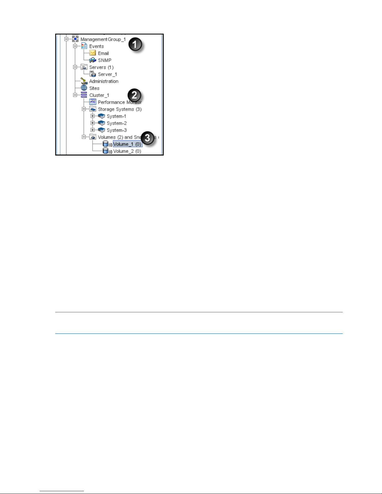
Figure 1 The SAN/iQ software storage hierarchy
1. Management group
2. Cluster
3. Volume
To complete this wizard, you will need the following information:
• A name for the management group.
• A storage system discovered on the network and then configured for RAID and the Network
settings
• DNS domain name, suffix, and server IP address for email event notification
• IP address or hostname and port of your email (SMTP) server for event notification
• A name for the cluster
• Virtual IP address to use for the cluster
• A name for the volume
• The size of the volume
NOTE: Names of management groups, clusters, volumes, and snapshots cannot be changed in
the future without deleting the management group.
Enabling server access to volumes
Create a server or server cluster to connect application servers to volumes. To create a server or
server cluster, you must first have created a management group, a cluster, and at least one volume.
You should also plan the following:
• The application servers that need access to volumes.
• The iSCSI initiator you plan to use. You need the server’s initiator name, and CHAP information
if you plan to use CHAP.
• For Fibre Channel access, have two Fibre Channel-enabled storage systems in the management
group.
See “Controlling server access to volumes” (page 197) for more information.
16 Getting started
Page 17

Using the Map View
The Map View tab is available for viewing the relationships between management groups, servers,
sites, clusters, volumes and snapshots. When you log in to a management group, there is a Map
View tab for each of those elements in the management group. For example, when you want to
make changes such as moving a volume to a different cluster, or deleting shared snapshots, the
Map View allows you to easily identify how many snapshots and volumes are affected by such
changes.
The Map View pane contains display tools to control and manipulate the view. The display tools
are available from the Map View Tasks menu or from the tool bar across the top of the pane. The
tools function the same from either the tool bar or the Map View tasks menu.
Using the display tools
Use these tools, described in Table 1 (page 17), to select specific areas of the map to view, zoom
in on, rotate, and move around the window. If you have a complex configuration, use the Map
View tools to easily view and monitor the configuration.
Table 1 Map View display tools
FunctionTool Icon
Zoom In—incrementally magnifies the Map View window.
Zoom Out—incrementally reduces the Map View window.
Magnify—creates magnification area, like a magnifying
glass, that you can move over sections of the map view.
Note that the magnify tool toggles on and off. You must
click the icon to use it, and you must click the icon to turn
it off.
Zoom to Fit—returns the map view to its default size and
view.
Select to Zoom—allows you to select an area of the map
view and zoom in on just that area.
Rotate—turns the map view 90 degrees at a time.
You can left-click in the Map View window and drag the
map around the window
Click and drag
Using views and layouts
The views and layouts differ for each element of your network that uses the map view.
For views and layouts available, see:
• Working with management groups, “Management group map view tab” (page 106)
• Controlling server access to volumes, “Viewing the relationship between storage systems,
volumes, and servers” (page 204)
• Sites, HP LeftHand Storage Multi-Site Configuration Guide
• Clusters, “Cluster Map View” (page 133)
• Volumes and Snapshots, “Viewing the volume map” (page 158)
• SmartClone volumes, “Using views” (page 191)
Using the Map View 17
Page 18
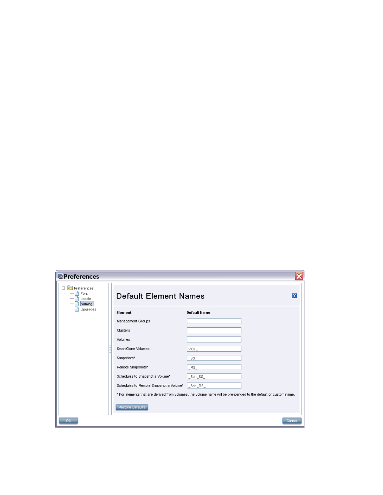
Setting preferences
Use the Preferences window to set the following:
• Font size in the CMC
• Locale for the CMC. The locale determines the language displayed in the CMC.
• Naming conventions for storage elements
• Online upgrade options. See the HP LeftHand Storage Upgrade Instructions.
Setting the font size and locale
Use the Preferences window, opened from the Help menu, to set font size and locale in the CMC.
Font sizes from 9 through 16 are available.
The CMC obtains the locale setting from your computer. If you change the locale on your computer
and open the CMC, it uses the new locale, if available in the CMC.
You can override the locale setting from your computer by selecting a different locale in the CMC.
Changing the locale in the CMC affects the language of the text that appears in the CMC and in
the online help.
After changing the locale, you must close and reopen the CMC to see the change.
Setting naming conventions
Use the Preferences window, opened from the Help menu, to set naming conventions for elements
you create when building the HP LeftHand Storage. You can use the default values or create your
own set of customized values.
When you install the CMC for the first time, or upgrade from release 7.0.x, default names are
enabled for snapshots, including schedules to snapshot a volume, and for SmartClone volumes.
No default names are provided for management groups, clusters, and volumes.
Figure 2 Default naming conventions for snapshots and SmartClone volumes
Changing naming conventions
Change the elements that use a default naming convention or change the naming convention itself.
18 Getting started
Page 19

If you use the given defaults, the resulting names look like those in Table 2 (page 19). Notice that
the volume name carries into all the snapshot elements, including SmartClone volumes, which are
created from a snapshot.
Table 2 Example of how default names work
ExampleDefault nameElement
VOL_VOL_ExchLogs_SS_3_1VOL_SmartClone Volumes
VOL_ExchLogs_SS_1_SS_Snapshots
VOL_RemoteBackup_RS_1_RS_Remote Snapshots
VOL_ExchLogs_Sch_SS_2.1_Sch_SS_Schedules to Snapshot a Volume
VOL_ExchLogs_Sch_RS_2_Pri.1,
VOL_RemoteBackup_Sch_RS_1_Rmt.1
_Sch_RS_Schedules to Remote Snapshot a
Volume
If you delete all the default names from the Preferences Naming window, the only automatically
generated naming elements that remain will incrementally number a series of snapshots or
SmartClone volumes.
Troubleshooting
Storage systems not found
If the network has a lot of traffic, or if a storage system is busy reading or writing data, it may not
be found when a search is performed. Try the following steps to find the storage system.
1. If the storage system you are looking for does not appear in the navigation window, search
again using the Find menu.
2. If you have searched using Auto Discover by Broadcast, try adding individual IP addresses
and clicking Find.
3. If you have searched by individual IP addresses, try searching by Auto Discover by Broadcast
instead.
4. If searching again does not work, try the following:
• Check the physical connection of the storage system.
• Wait a few minutes and try the search again. If activity to the storage system was frequent,
the storage system might not have responded to the search.
Other problems can prevent the CMC from finding a storage system:
• Extremely high network traffic to and from the storage system.
• The IP address could have changed if the storage system is configured to use DHCP (not
recommended).
• The storage system may have been rebooted and is not yet online.
• Power could have failed to a network switch to which the storage system is connected.
• The CMC might be running on a system that is on a different physical network than the storage
system. Poor network routing performance at the site may severely affect performance of the
CMC.
Configuring remote support for HP LeftHand Storage
If you are using HP remote support, Table 3 (page 20) lists the required configuration tasks.
Troubleshooting 19
Page 20

Table 3 CMC setup for remote support
For more information, seeTask
“Enabling SNMP agents” (page 92)Enable SNMP on each storage system
“Adding SNMP traps” (page 93)Set the SNMP trap recipient to IP address of the system
where the remote support client is installed
Your network administratorOpen port 8959 (used for the CLI)
“Adding an administrative user” (page 76)Set the management group login and password for a
read-only (View_Only_Administrator group) user
20 Getting started
Page 21
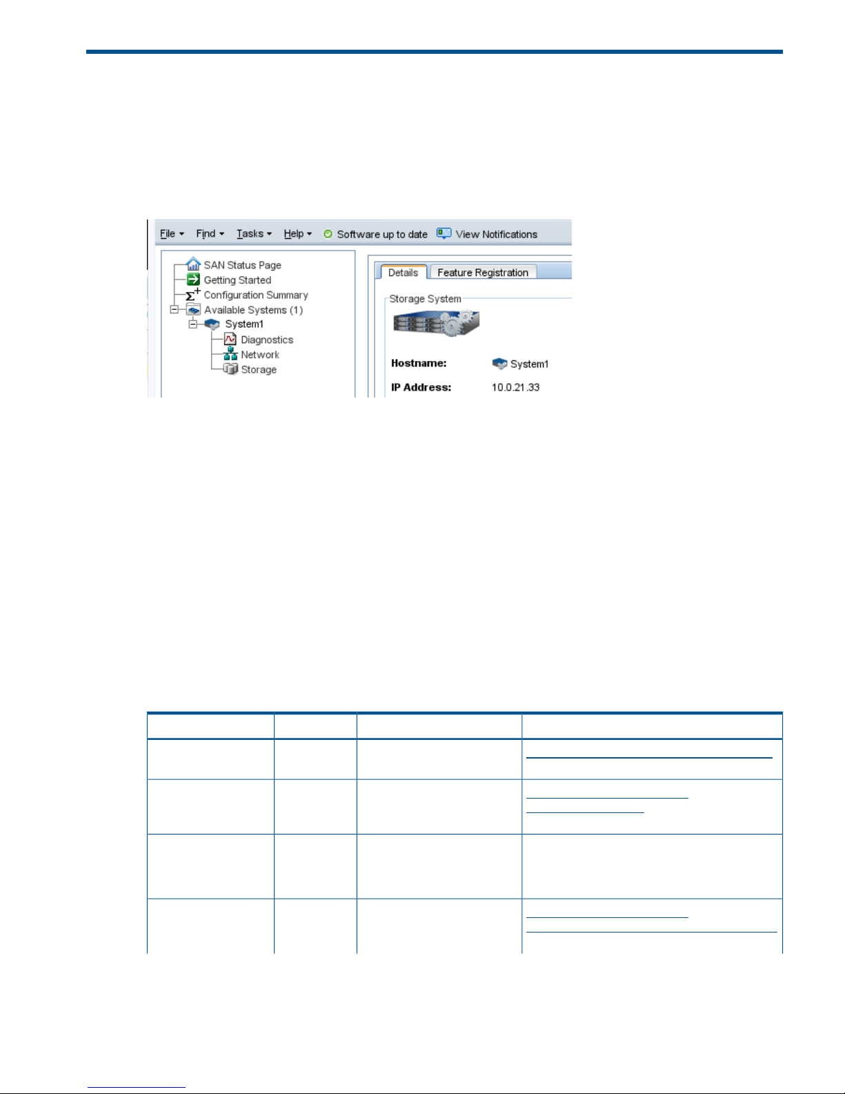
2 Working with storage systems
Storage systems displayed in the navigation window have a tree structure of configuration categories
under them, as shown in Figure 3 (page 21). The configuration categories provide access to the
configuration tasks for individual storage systems. You must configure each storage system
individually before using it in a cluster.
Figure 3 Storage system configuration categories
The configuration categories include the following:
• Diagnostics—Run hardware diagnostic tests, view current hardware status and configuration
information, and save log files.
• Network—For each storage system, configure and manage the network settings, including
network interface cards (NICs), the routing table, and which interface carries SAN/iQ
communications.
• Storage—Manage RAID and the individual disks in the storage system.
Identifying the storage system hardware
Each HP LeftHand storage system is based on a specific HP platform. For general information about
the underlying hardware of your HP LeftHand Storage model, such as LEDs, component identification,
and replacing components, see the platform-specific documentation. Table 4 (page 21) identifies
the HP platform used for each LeftHand model and a link to related information.
Table 4 HP platform identification
LinkDocumentationHP platformHP LeftHand model
http://www.hp.com/support/DL320s_UG_enHP ProLiant DL320s User
Guide
ProLiant
DL320s
NSM 2120
http://www.hp.com/support/
DL185Gen5_MSG_en
HP ProLiant DL185
Generation 5 Maintenance
and Service Guide
ProLiant
DL185 G5
HP LeftHand P4300
HP LeftHand P4500
Contact HP Support for more information as this
guide is not publicly available.
HP SE1220 Maintenance and
Service Guide
SE1220HP P4300 G2
HP P4500 G2
HP P4900 G2
http://www.hp.com/support/
HP_P4800_G2_SAN_Solution_BladeSystem_MG_en
HP P4800 G2 SAN Solution
for BladeSystem Maintenance
Guide
ProLiant
BL460c G7
P4800 G2
Identifying the storage system hardware 21
Page 22

Table 4 HP platform identification (continued)
LinkDocumentationHP platformHP LeftHand model
http://www.hp.com/support/
BL460cG7_Server_Blade Maintenance and
Service Blade_MSG_en
HP ProLiant BL460c G7
Server Blade Maintenance
and Service Guide
http://www.hp.com/go/proliantgen8/docsHP ProLiant DL360p Gen8
Server Maintenance and
Service Guide
ProLiant
DL360p G8
HP LeftHand 4130
HP LeftHand 4330
Storage system tasks
Logging in to and out of storage systems
When storage systems are in the Available pool, you log in without a user name or password.
Simply click the link Log in to view. When you use the Management Group, Clusters and Volumes
wizard, selecting a storage system to use automatically logs in to that storage system. You can
find the link to log in at the following locations:
• From the Available systems list in the Navigation window
• On individual storage system Details tabs
Logging out of a storage system
1. Select a storage system in the navigation window.
2. Right-click and select Log Out.
NOTE: If you are logged in to multiple storage systems, you must log out of each storage system
individually.
Changing the storage system hostname
The storage system arrives configured with a default hostname. Change the hostname as follows:
1. In the navigation window, log in to the storage system.
2. On the Details tab, click Storage System Tasks and select Edit Hostname.
3. Enter the new name, and click OK.
4. Click OK to finish.
NOTE: Add the hostname and IP pair to the hostname resolution methodology employed in your
environment, for example, DNS or WINS.
Locating the storage system in a rack
The Set ID LED illuminates lights on the physical storage system to aid in physically locating that
storage system in a rack. The Set ID LED is available depending on the model of the storage system.
1. Select a storage system in the navigation window and log in.
2. Click Storage System Tasks on the Details tab and select Set ID LED On.
The ID LED on the front of the storage system is now a bright blue. Another ID LED is located
on the back of the storage system.
When you click Set ID LED On, the status changes to On.
3. Select Set ID LED Off when you have finished.
The LED on the storage system turns off.
22 Working with storage systems
Page 23
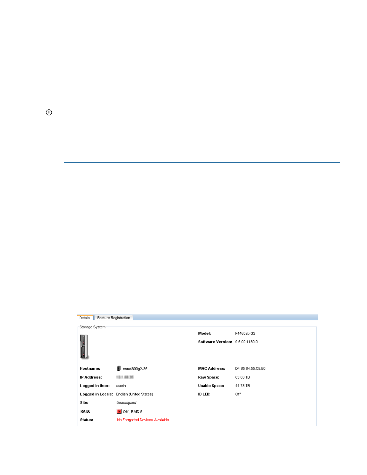
Powering off or rebooting the storage system
Reboot or power off the storage system from the CMC. Set the amount of time before the process
begins, to ensure that all activity to the storage system has stopped.
Powering off the storage system through the CMC physically powers it off. The CMC controls the
power down process so that data is protected.
Powering off an individual storage system is appropriate for servicing or moving that storage
system. However, if you want to shut down more than one storage system in a management group,
you should shut down the management group instead of individually powering off the storage
systems in that group. See “Shutting down a management group” (page 114).
IMPORTANT:
• Before powering off or rebooting the storage system, ensure that volumes will not go offline
by checking the storage system Availability tab. See “Determining volume and snapshot
availability ” (page 25).
• You should also verify that you have the proper number of managers and possibly a Failover
Manager to ensure that quorum is maintained. See “Managers and quorum” (page 119).
Powering on or off, or rebooting storage systems with modular components
Some storage systems are comprised of modular components, that may include:
• Disk enclosure
• Server blades enclosure
• System controller
The P4800 is an example of a storage system that is comprised of modular components.
Power on the components in the following order:
1. Disk enclosure.
2. Server blades enclosure or system controller.
Allow up to 6 minutes for the system controller to come up completely and be discovered by
the CMC. If the CMC cannot find the storage system after 6 minutes, contact Customer Support.
3. If you do not power on the disk enclosure first, the Storage System Details tab shows the status
with No Formatted Devices Available.
Figure 4 Disk enclosure not found as shown in Details tab
Powering off or rebooting the storage system 23
Page 24

When powering off the storage system, be sure to power off the components in the following order:
1. Power off the server blades enclosure or system controller from the CMC as described in
“Powering off the storage system” (page 24).
2. Manually power off the disk enclosure.
When you reboot the storage system, use the CMC, as described in “Rebooting the storage system”
(page 24). This process reboots only the server blades enclosure or the system controller.
Rebooting the storage system
1. Select a storage system in the navigation window and log in.
2. Click Storage System Tasks on the Details tab and select Power Off or Reboot.
3. In the minutes field, enter the number of minutes before the reboot should begin.
Enter any whole number greater than or equal to 0. If you enter 0, the storage system reboots
shortly after you confirm the reboot.
NOTE: If you enter 0 for the value when rebooting, you cannot cancel the action. Any value
greater than 0 allows you to cancel before the reboot actually takes place.
4. Select Reboot to perform a software reboot without a power cycle.
5. Click OK.
The storage system starts the reboot in the specified number of minutes. The reboot takes
several minutes.
6. Search for the storage system to reconnect the CMC to the storage system once it has finished
rebooting.
Powering off the storage system
1. Log in to the storage system.
2. Select Storage System Tasks on the Details tab and select Power Off or Reboot.
3. Select Power Off.
The button changes to Power Off.
4. In the minutes field, enter the number of minutes before the powering off should begin.
Enter any whole number greater than or equal to 0. If you enter 0, the storage system powers
off shortly after you confirm the power off.
NOTE: If you enter 0 for the value when powering off, you cannot cancel the action. Any
value greater than 0 allows you to cancel before the power off actually takes place.
5. Click Power Off.
24 Working with storage systems
Page 25
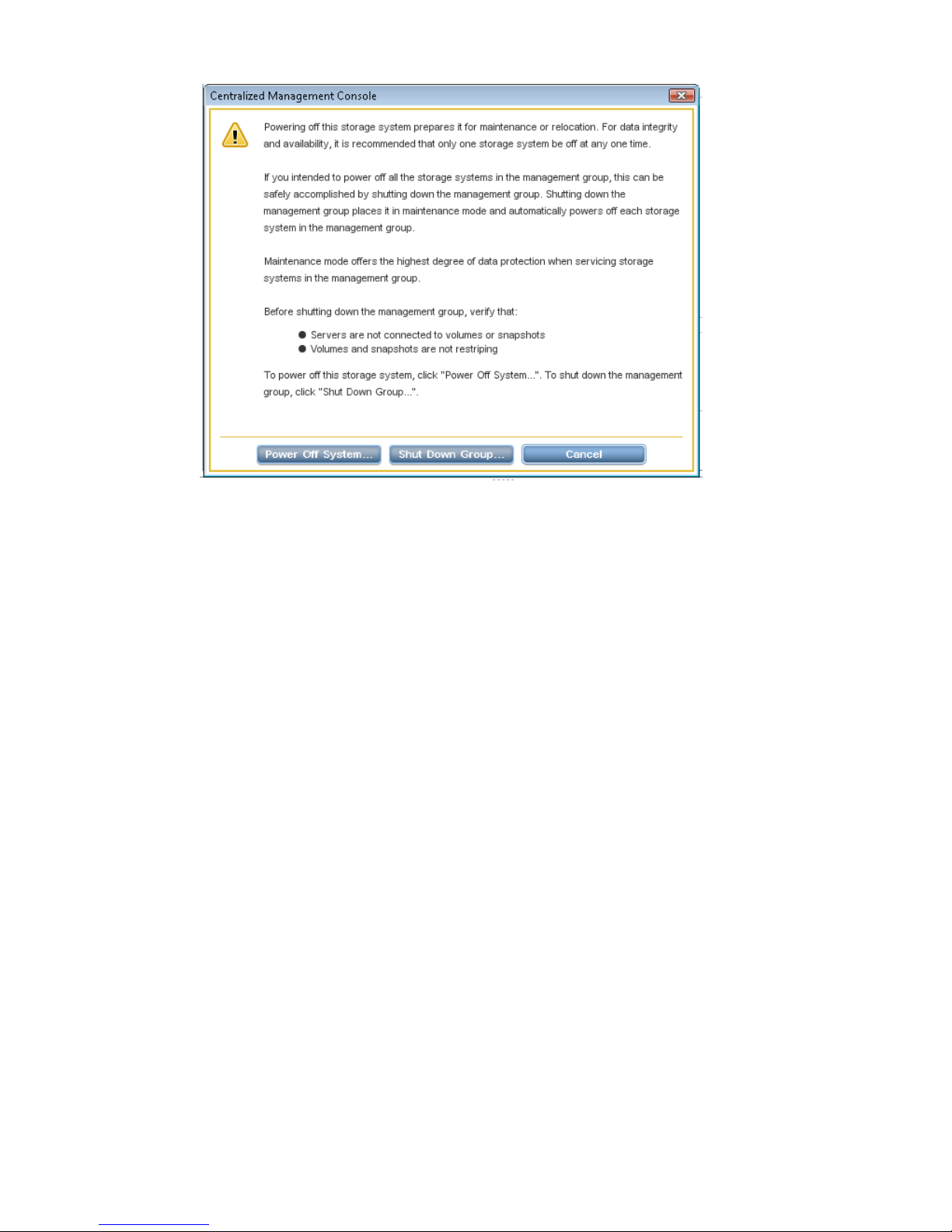
Figure 5 Confirming storage system power off
Depending on the configuration of the management group and volumes, your volumes and
snapshots can remain available.
Upgrading SAN/iQ on storage systems
The CMC enables online upgrades for storage systems, including the latest software releases and
patches. See the HP LeftHand Storage Upgrade Instructions.
Registering advanced features for a storage system
Using the Feature Registration tab, register individual storage systems for advanced features.
For more information about registering advanced features, see “Registering advanced features”
(page 226).
Determining volume and snapshot availability
The Availability tab displays which volumes’ and snapshots’ availability depends on this storage
system staying online. Details include the data protection level and what factors contribute to the
availability status, such as the status of storage systems participating in any replication or a RAID
restripe in progress.
Upgrading SAN/iQ on storage systems 25
Page 26
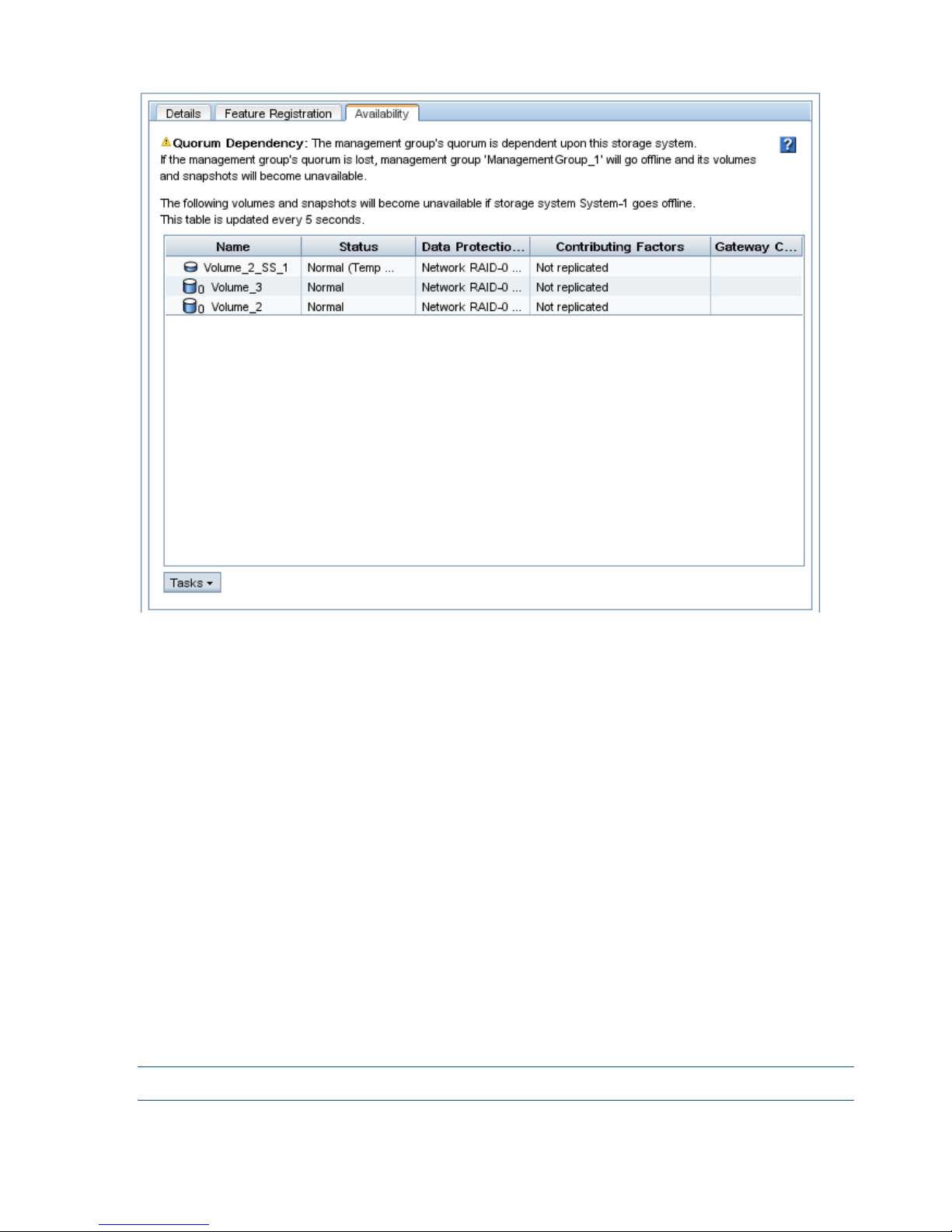
Figure 6 Availability tab
Checking status of dedicated boot devices
Some storage systems contain either one or two dedicated boot devices. Dedicated boot devices
may be compact flash cards or hard drives. If a storage system has dedicated boot devices, the
Boot Devices tab appears in the Storage configuration category. Storage systems that do not have
dedicated boot devices will not display the Boot Devices tab.
In storage systems with two dedicated boot devices, both devices are active by default. If necessary,
compact flash cards can be deactivated or activated using the buttons on this tab. However, you
should only take action on these cards if instructed by HP Technical Support.
Checking boot device status
View dedicated boot device status in the Boot Devices tab window in the Storage category in the
storage system tree.
Getting there
1. Select a storage system in the navigation window and log in if necessary.
2. Open the tree below the storage system and select Storage.
3. Select the Boot Devices tab.
The status of each dedicated boot device on the storage system is listed in the Status column.
Table 5 (page 27) describes the possible status for boot devices.
NOTE: Some statuses only occur in a storage system with two boot devices.
26 Working with storage systems
Page 27

Table 5 Boot device status
DescriptionBoot device status
The device is synchronized and ready to be used.Active
The device is ready to be removed from the storage system.
It will not be used to boot the storage system.
Inactive
The device encountered an I/O error and is not ready to
be used.
Failed
The device has not yet been used in a storage system. It is
ready to be activated.
Unformatted
The device is not recognized as a boot device.Not Recognized
The device cannot be used. (For example, the compact
flash card is the wrong size or type.)
Unsupported
NOTE: When the status of a boot device changes, an event is generated. See “Alarms and events
overview” (page 84).
Replacing a dedicated boot device
If a boot hard drive fails, you will see an event that the boot device is faulty. Replace it with a new
drive. The boot device drives support hot swapping and do not require activation.
Checking status of dedicated boot devices 27
Page 28
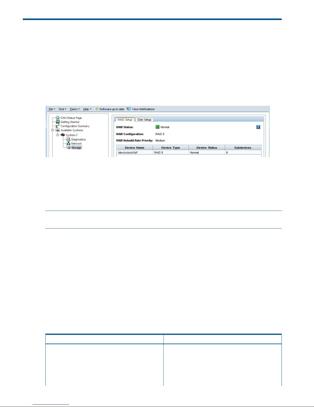
3 Configuring RAID and Managing Disks
For each storage system, you can select the RAID configuration and the RAID rebuild options, and
monitor the RAID status. You can also review disk information and, for some models, manage
individual disks.
Getting there
1. In the navigation window, select a storage system and log in if necessary.
2. Open the tree under the storage system and select the Storage category.
Figure 7 Viewing the storage configuration category for a storage system
Columns in the RAID Setup tab show four categories:
• Device Name
• Device Type or the RAID level
• Device Status
• Subdevices
NOTE: For hardware-specific LED information for your storage system, see “Identifying the storage
system hardware” (page 21) for document titles and document links.
Configuring and managing RAID
Managing the RAID settings of a storage system includes:
• Choosing the right RAID configuration for your storage needs
• Setting or changing the RAID configuration, if necessary
• Setting the rate for rebuilding RAID
• Monitoring the RAID status for the storage system
• Reconfiguring RAID when necessary
RAID Levels
The availability of certain RAID levels is determined by the number of storage system hard drives.
Table 6 Descriptions of RAID levels
DescriptionRAID level
Offers a good combination of data protection and
performance. RAID 1 or drive mirroring creates fault
RAID 1 – Mirroring
tolerance by storing duplicate sets of data on a minimum
of two hard drives. There must be an even number of drives
for RAID 1. RAID 1 and RAID 1+0(10) are the most costly
fault tolerance methods because they require 50 percent
of the drive capacity to store the redundant data. RAID 1
28 Configuring RAID and Managing Disks
Page 29

Table 6 Descriptions of RAID levels (continued)
DescriptionRAID level
mirrors the contents of one hard drive in the array onto
another. If either hard drive fails, the other hard drive
provides a backup copy of the files and normal system
operations are not interrupted.
Offers the best combination of data protection and
performance. RAID 1+0 or drive mirroring creates fault
RAID 1+0 – Mirroring and Striping
tolerance by storing duplicate sets of data on a minimum
of four hard drives. There must be an even number of drives
for RAID 1+0. RAID 1+0(10) and RAID 1 are the most
costly fault tolerance methods because they require 50
percent of the drive capacity to store the redundant data.
RAID 1+0(10) first mirrors each drive in the array to
another, and then stripes the data across the mirrored pair.
If a physical drive fails, the mirror drive provides a backup
copy of the files and normal system operations are not
interrupted. RAID 1+0(10) can withstand multiple
simultaneous drive failures, as long as the failed drives are
not mirrored to each other.
Offers the best combination of data protection and usable
capacity while also improving performance over RAID 6.
RAID 5
RAID 5 stores parity data across all the physical drives in
the array and allows more simultaneous read operations
and higher performance. If a drive fails, the controller uses
the parity data and the data on the remaining drives to
reconstruct data from the failed drive. The system continues
operating with a slightly reduced performance until you
replace the failed drive. RAID 5 can only withstand the
loss of one drive without total array failure. It requires an
array with a minimum of three physical drives. Usable
capacity is N-1 where N is the number of physical drives
in the logical array.
Offers the best data protection and is an extension of RAID
5. RAID 6 uses multiple parity sets to store data and can
RAID 6
therefore tolerate up to 2 drive failures simultaneously.
RAID 6 requires a minimum of 4 drives. Performance is
lower than RAID 5 due to parity data updating on multiple
drives. RAID 6 uses two disk for parity; its fault tolerance
allows two disks to fail simultaneously. Usable capacity is
N-2 where N is the number of physical drives in the logical
array.
Explaining RAID devices in the RAID setup report
In the Storage category, the RAID Setup tab lists the RAID devices in the storage system and provides
information about them. An example of the RAID setup report is shown in Figure 8 (page 29).
Information listed in the report is described in Table 7 (page 30).
Figure 8 RAID setup report
Explaining RAID devices in the RAID setup report 29
Page 30

RAID devices by RAID type
Each RAID type creates different sets of RAID devices. Table 7 (page 30) contains a description
of the variety of RAID devices created by the different RAID types as implemented on various
storage systems.
Table 7 Information in the RAID setup report
Describes thisThis item
The disk sets used in RAID. The number and names of
devices varies by storage system and RAID level.
Device Name
The RAID level of the device. For example, in a HP P4300
G2, RAID 5 displays a Device Type of RAID 5 and
subdevices as 8.
Device Type
The RAID status of the device.
Status is one of the following:
Device Status
• Normal—green
• Degraded—yellow
• Off—red
• Rebuilding—blue
The number of disks included in the device.Subdevices
Virtual RAID devices
If you are using the VSA, the only RAID available is virtual RAID. After installing the VSA, virtual
RAID is configured automatically if you first configured the data disk in the VI Client.
HP recommends installing VSA for vSphere on top of a server with a RAID 5 or RAID 6 configuration.
Planning the RAID configuration
Plan the RAID configuration for storage systems based on a balance between data high availability
or fault tolerance, I/O performance, and usable capacity.
CAUTION: Plan your RAID configuration carefully. After you have configured RAID, you cannot
change the RAID configuration without deleting all data on the storage system.
Data protection
Keeping multiple copies of your data ensures that data is safe and remains available in the case
of disk failure. HP recommends using both disk RAID and Network RAID to insure high availability:
• Configure RAID 1, RAID 10, RAID 5, or RAID 6 within each storage system to ensure data
redundancy.
• Always use Network RAID to mirror data volumes across storage systems in a cluster, regardless
of RAID level, for added data protection and high availability .
Using RAID for data redundancy
Within each storage system, RAID 1 or RAID 10 ensures that two copies of all data exist. If one
of the disks in a RAID pair goes down, data reads and writes continue on the other disk. Similarly,
RAID 5 or RAID 6 provides redundancy by spreading parity evenly across the disks in the set.
If one disk in a RAID 5 set, or two disks in a RAID 6 set goes down, data reads and writes continue
on the remaining disks in the set.
RAID protects against failure of disks within a storage system, but not against failure of an entire
storage system. For example, if network connectivity to the storage system is lost, then data reads
and writes to the storage system cannot continue.
30 Configuring RAID and Managing Disks
Page 31

NOTE: If you plan on using clusters with only a single storage system, use RAID 1 and RAID 10,
RAID 5, or RAID 6 to ensure data redundancy within that storage system.
Using Network RAID in a cluster
A cluster is a group of storage systems across which data can be protected by using Network
RAID. Network RAID protects against the failure of a RAID disk set within a storage system, failure
of an entire storage system or external failures like networking or power. For example, if an entire
storage system in a cluster becomes unavailable, data reads and writes continue because the
missing data can be obtained from the other storage systems.
Using disk RAID with Network RAID in a cluster
Always use Network RAID in a cluster to protect volumes across storage systems. The redundancy
provided by RAID 10, RAID 5, or RAID 6 ensures availability at the storage system level. Using
Network RAID for volumes in a cluster ensures availability at the cluster level. For example:
• Using Network RAID, up to three copies of a volume can be created on a cluster of three
storage systems. The Network RAID configuration ensures that two of the three storage systems
can go offline and the volume is still accessible.
• Configuring RAID 10 on these storage systems means that each of these three copies of the
volume is stored on two disks within the storage system, for a total of six copies of each volume.
For a 50 GB volume, 300 GB of disk capacity is used.
RAID 5 uses less disk capacity than RAID 1 or RAID 10, so it can be combined with Network RAID
and still use capacity efficiently. One benefit of configuring RAID 5 in storage systems that use
Network RAID in a cluster is that if a single disk goes down, the data on that storage system can
be rebuilt using RAID instead of requiring a complete copy from another storage system in the
cluster. Rebuilding the disks within a single set is faster and creates less of a performance impact
to applications accessing data than copying data from another storage system in the cluster.
RAID 6 provides similar space benefits to RAID 5, with the additional protection of being able to
survive the loss of up to two drives.
NOTE: If you are protecting volumes across a cluster, configuring the storage system for RAID 1
or RAID 10 consumes half the capacity of the storage system. Configuring the storage system for
RAID 5 provides redundancy within each storage system while allowing most of the disk capacity
to be used for data storage. RAID 6 provides greater redundancy on a single storage system, but
consumes more disk space than RAID 5.
Table 8 (page 31) summarizes the differences in data availability and safety of the different RAID
levels on stand-alone storage systems compared with those RAID levels with Network RAID
configured volumes in a cluster.
Table 8 Data availability and safety in RAID configurations
Data availability if an entire individual
storage system fails or if network
connection to a storage system is lost
Data safety and availability during
disk failure
Configuration
NoNoStand-alone storage systems
NoYes. In any configuration, 1 disk per
mirrored pair can fail.
Stand-alone storage systems, RAID 1,
RAID 10, RAID 10 + spare
NoYes, for 1 disk per arrayStand-alone storage systems, RAID 5
NoYes, for 2 disks per arrayStand-alone storage systems, RAID 6
YesYes. 1 disk per RAID set can fail
without copying from another storage
system in the cluster.
Volumes configured with Network
RAID-10 or greater on clustered
storage systems, RAID 5
Planning the RAID configuration 31
Page 32

Table 8 Data availability and safety in RAID configurations (continued)
Data availability if an entire individual
storage system fails or if network
connection to a storage system is lost
Data safety and availability during
disk failure
Configuration
YesYes. 2 disks per RAID set can fail
without copying from another storage
system in the cluster.
Volumes configured with Network
RAID-10 or greater on clustered
storage systems, RAID 6
YesDepends on the underlying RAID
configuration of the storage system on
Volumes configured with Network
RAID-10 or greater on clustered VSAs
with virtual RAID which the VSA is installed. HP
recommends configuring RAID 5 or
RAID 6.
Mixing RAID configurations
You may mix storage systems with different configurations of RAID within a cluster. This allows you
to add new storage systems with different RAID levels. However, be certain to calculate the capacity
of additional storage systems configured with the desired RAID level, because the cluster operates
at the smallest usable per-storage system capacity.
For instance, your SAN uses four 12 TB HP P4500 G2s configured with RAID 10. You purchase
two additional 12 TB HP P4500 G2s which you want to configure with RAID 5.
In the existing cluster, a single 12 TB HP P4500 G2 configured with RAID 10 provides 6 TB of
usable storage. A single 12 TB HP P4500 G2 configured with RAID 5 provides 9 TB of usable
storage. However, due to the restrictions of how the cluster uses capacity, the 12 TB HP P4500
G2 configured with RAID 5 will be limited to 6 TB per storage system.
In general, the best practice is to avoid mixing configurations of various numbers or capacities of
drives, so that the SAN fully utilizes the available capacity of each cluster.
Setting RAID rebuild rate
Choose the rate at which the RAID configuration rebuilds if a disk is replaced.
NOTE: The RAID rebuild rate cannot be set on a VSA, since there is no physical hardware to
rebuild.
General guidelines for setting the RAID rebuild rate
Use the following guidelines when deciding where to set the RAID rebuild rate:
• Setting the rate higher is preferred for rebuilding RAID quickly and protecting data. However,
it slows down user access to data.
• Setting the rate lower allows users quicker access to data during the rebuild, but slows the
rebuild rate.
Setting the RAID rebuild rate
1. In the navigation window, log in to a storage system and select the Storage category.
2. On the RAID Setup tab, click RAID Setup Tasks and select the RAID Rebuild Rate Priority choice.
3. Change the rebuild setting as desired on the RAID Rebuild Rate Priority window.
4. Click OK.
The setting is then ready when a RAID rebuild takes place.
32 Configuring RAID and Managing Disks
Page 33

Reconfiguring RAID
Reconfiguring RAID on a storage system or a VSA destroys any data stored on that storage system.
For VSAs, there is no alternate RAID choice, so the only outcome for reconfiguring RAID is to wipe
out all data.
• Changing preconfigured RAID on a new storage system
RAID must be configured on individual storage systems before they are added to a management
group. To change the preconfigured RAID level of a storage system, make the change before
you add the storage system to a management group.
• Changing RAID on storage systems in management groups
You cannot reconfigure RAID on a storage system that is already in a management group. To
change the RAID configuration for a storage system that is in a management group, you must
first remove it from the management group.
CAUTION: Changing the RAID configuration will erase all the data on the disks.
To reconfigure RAID
1. In the navigation window, log in to the storage system and select the Storage category.
2. On the RAID Setup tab, click RAID Setup Tasks and select Reconfigure RAID.
3. Select the RAID configuration from the list.
4. Click OK.
5. Click OK on the message that opens.
RAID starts configuring.
NOTE: A storage system may take several hours for the disks to synchronize in a RAID 10, RAID
5, or RAID 6 configuration. During this time, performance will be degraded. When the RAID status
on the RAID Setup tab shows Normal, the disks provide fully operational data redundancy, and
performance returns to normal.
Configuring RAID for a P4800 G2 with 2 TB drives
RAID 6 is the default configuration for P4800 G2 storage blades with 2 TB capacity or greater.
HP recommends using the default configuration.
• Configuring the disks to RAID 5 takes a few minutes in the CMC. You must first remove the
storage system from the management group. Once configuration is complete, you can add
the storage system to the management group, while RAID 5 initialization occurs in the
background. The CMC is available during initialization and you can track the status of the
initialization using the Hardware Information tab in the CMC. The RAID 5 initialization takes
a number of days, depending upon how much I/O is going to the storage system. System
performance is impacted if the system is actively participating in a cluster that is hosting storage
volumes.
• If reconfiguring the disks to RAID 6 is necessary, the process takes approximately six hours.
You must first remove the storage system from the management group. RAID 6 initialization
must finish before adding the storage system to the management group. During initialization,
the CMC is unavailable. However, you should leave the CMC open while RAID initialization
continues, and track the status of the initialization on the status bar at the bottom of the CMC.
When RAID 6 initialization has finished, the CMC becomes available again, and you can
add the storage system to the management group.
Reconfiguring RAID 33
Page 34

Monitoring RAID status
RAID is critical to the operation of the storage system. If RAID has not been configured, the storage
system cannot be used. Monitor the RAID status of a storage system to ensure that it remains normal.
If the RAID status changes, a CMC event is generated. For more information about events and
event notification, see “Alarms and events overview” (page 84).
Data reads and writes and RAID status
A RAID status of Normal, Rebuild, or Degraded all allow data reads and writes. The only time
data cannot be written to and read from the storage system is if the RAID status shows Off.
Data redundancy and RAID status
In a RAID 1, RAID 10, or RAID 5 configuration, when RAID is degraded, there is no full data
redundancy. Therefore, data is at additional risk if there is a disk failure when RAID is degraded.
In RAID 6, when RAID is degraded due to a single drive failure, the data is still not at risk for a
second failure. However, if it is degraded due to the failure of two drives, then data would be at
risk if another drive failed.
CAUTION: In a degraded RAID 1 or RAID 10 configuration, loss of a second disk within a pair
results in data loss. In a degraded RAID 5 configuration, loss of a second disk results in data loss.
In a degraded RAID 6 configuration, the loss of three drives results in data loss.
The RAID status is located at the top of the RAID Setup tab in Storage. RAID status also appears
in the Details tab on the main CMC window when a storage system is selected in the navigation
window.
Figure 9 Monitoring RAID status on the main CMC window
1. RAID status
The status displays one of five RAID states.
• Normal—RAID is synchronized and running. No action is required.
• Rebuilding—A new disk has been inserted in a drive bay, or a hot spare has been activated,
and RAID is currently rebuilding. No action is required.
• Degraded—RAID is degraded. A disk may have failed or have been removed from its bay.
For hot-swap storage systems, simply replace the faulty, inactive, uninitialized, or missing disk.
• Off—Data cannot be stored on the storage system. The storage system is offline and flashes
in the navigation window.
• None—RAID is unconfigured.
34 Configuring RAID and Managing Disks
Page 35

Managing disks
Use the Disk Setup tab to monitor disk information and perform disk management tasks as listed
in Table 9 (page 35).
Table 9 Disk management tasks for storage systems
Where availableDisk setup function
All storage systemsMonitor disk information
Storage systems running version 9.5.01 or laterView Disk Details
Storage systems with this specific capabilityActivate Drive ID LEDs
Getting there
1. In the navigation window, select a storage system.
2. Select the Storage category in the tree below it.
3. Click the Disk Setup tab.
Reading the disk report on the Disk Setup tab
The Disk Setup tab provides a status report of the individual disks in a storage system.
Figure 10 (page 35) shows the Disk Setup tab and Table 10 (page 36) describes the corresponding
disk report.
Figure 10 Example of columns in the Disk Setup tab
Managing disks 35
Page 36

Table 10 Description of items on the disk report
DescriptionColumn
Corresponds to the physical slot in the storage system.Disk
Status is one of the following:Status
• Active—green (on and participating in RAID)
• Uninitialized—yellow (is not part of an array)
• Inactive—yellow (is part of an array, and on, but not
participating in RAID)
• Marginal—yellow
• Off or removed—red
• Hot spare—green (for RAID configurations that support
hot spares)
• Hot spare down—red
Drive health is one of the following:Health
• Normal
• Marginal (predictive failure status indicating “replace
as soon as convenient”)
• Predictive Failure (predictive failure status indicating
“replace immediately”)
Indicates if it is safe to hot-remove a disk.Safe to Remove
The model of the disk.Model
The serial number of the disk.Serial Number
The class (type) of disk, for example, SATA 3.0 GB.Class
Indicates the estimated wear life remaining for SSD drives.
Status is one of the following:
Wear Life Remaining (P4900 G2 only)
• Normal—Green; drive is good
• Aging—Yellow; drive is at 5% of remaining estimated
life
• Degraded—Yellow; drive is at 2% of remaining
estimated life
• Failing—Red; drive has estimated an 90 days of
remaining life
• Worn out—Red; drive is at 0% of remaining estimated
life
• Failed—Red; drive has failed and writes are not
permitted
The data storage capacity of the disk.Capacity
SSD drives and wear life
The wear life statistics for SSD drives report drive usage so that drives can be replaced before they
wear out. See “Replacing disks appendix” (page 243) for more information.
If all the SSD drives approach the end of their wear life at the same time, and you plan to replace
all the drives in the storage system, use one of the following methods to preserve the data while
replacing the drives:
• Migrate the volumes and snapshots from the cluster containing the storage system with the
SSD drives to a different cluster in the management group. Remove the storage system from
the cluster and the management group, replace the drives and rebuild RAID on the drives.
36 Configuring RAID and Managing Disks
Page 37

Then return the storage system to the cluster and migrate the volumes and snapshots back to
the original cluster. “Changing the cluster—migrating a volume to a different cluster” (page 159).
• Perform a cluster swap, replacing the storage systems with the worn out SSD drives with
storage systems with new SSD drives. See “Upgrading the storage systems in a cluster using
cluster swap” (page 135).
NOTE: If replacing the SSD drives due to the wear life remaining status, the Repair Storage
System feature is not available because there is not a disk failure, indicated by a disk inactive or
disk off event in the Events list.
Verifying disk status
Check the Disk Setup window to determine the status of disks and to take appropriate action on
individual disks when preparing to replace them.
NOTE: For hardware-specific disk LED or component information for your storage system, see
“Identifying the storage system hardware” (page 21) for document titles and document links.
Viewing disk status for the VSA
For the VSA, the Disk Setup window shows 1 virtual disk.
Figure 11 Viewing the disk status of a VSA
NOTE: To change the size of the data disk in a VSA, see the HP LeftHand Storage VSA Installation
and Configuration Guide for instructions about recreating the disk in the VI Client.
Viewing disk status for the HP P4500 G2
The disks are labeled 1 through 12 in the Disk Setup window, shown in Figure 12 (page 38),and
correspond to the disk drives from top to bottom, left to right (Figure 13 (page 38)), when you are
looking at the front of the HP P4500 G2.
For the HP P4500 G2, the columns Health and Safe to Remove help you assess the health of a
disk and tell you whether or not you can replace it without losing data.
Managing disks 37
Page 38

Figure 12 Viewing the Disk Setup tab in a HP P4500 G2
Figure 13 Diagram of the drive bays in a HP P4500 G2
Viewing disk status for the HP P4300 G2
The disks are labeled 1 through 8 in the Disk Setup window, shown in Figure 14 (page 38), and
correspond to the disk drives from top to bottom, left to right ( Figure 15 (page 39)), when you
are looking at the front of the HP P4300 G2.
For the HP P4300 G2, the columns Health and Safe to Remove help you assess the health of a
disk and tell you whether or not you can replace it without losing data.
Figure 14 Viewing the Disk Setup tab in a HP P4300 G2
38 Configuring RAID and Managing Disks
Page 39

Figure 15 Diagram of the drive bays in a HP P4300 G2
Viewing disk status for the P4800 G2
The disks are labeled 1 through 35 in the Disk Setup window( Figure 16 (page 39)), and correspond
to the disk drives from top to bottom, left to right, (Figure 17 (page 39)), when you are looking at
the front of the P4800 G2.
Figure 16 Viewing the Disk Setup tab in a P4800 G2
Figure 17 Diagram of the drive bays in a P4800 G2
Viewing disk status for the HP P4900 G2
The disks are labeled 1 through 8 in the Disk Setup window (Figure 18 (page 40)), and correspond
to the disk drives from top to bottom, left to right (Figure 19 (page 40)), when you are looking at
the front of the HP P4900 G2.
Managing disks 39
Page 40

Figure 18 Viewing the Disk Setup tab in a HP P4900 G2
Figure 19 Diagram of the drive bays in a HP P4900 G2
Viewing disk status for the HP LeftHand 4130
The disks are labeled 1 through 4 in the Disk Setup window (Figure 20 (page 40)), and correspond
to the disk drives from top to bottom, left to right (Figure 21 (page 41)), when you are looking at
the front of the HP LeftHand 4130.
Figure 20 Viewing the Disk Setup tab in a HP LeftHand 4130
40 Configuring RAID and Managing Disks
Page 41

Figure 21 Diagram of the drive bays in a HP LeftHand 4130
Viewing disk status for the HP LeftHand 4330
The disks are labeled 1 through 8 in the Disk Setup window (Figure 22 (page 41)), and correspond
to the disk drives from top to bottom, left to right (Figure 23 (page 41)), when you are looking at
the front of the HP LeftHand 4330.
Figure 22 Viewing the Disk Setup tab in a HP LeftHand 4330
Figure 23 Diagram of the drive bays in a HP LeftHand 4330
Replacing a disk
The correct procedure for replacing a disk in a storage system depends upon a number of factors,
including the RAID configuration, the data protection level of volumes and snapshots, and the
number of disks being replaced. Replacing a disk in a storage system that is in a cluster requires
rebuilding data on the replaced disk.
Replacing a disk in a storage system includes the following basic steps.
• Planning for rebuilding data on either the disk or the entire storage system (all storage systems)
• Powering the disk off in the CMC (non-hot-swap storage systems)
• Physically replacing the disk in the storage system (all storage systems)
• Powering the disk on in the CMC (non-hot-swap storage systems)
• Rebuilding RAID on the disk or on the storage system (all storage systems)
Replacing a disk 41
Page 42

NOTE: Because of the nature of the SSD drive wear management and reporting, it is likely that
all the SSD drives in a system will wear out around the same time.
Table 11 (page 42) lists disk replacement requirements for specific configurations and storage
systems.
Table 11 Disk replacement requirements
RequirementsStorage system or configuration
RAID is normal and Safe to Remove status is yes. See
“Replacing disks in hot-swap storage systems” (page 42).
Hot-swap storage systems configured for RAID 1, 10, 5,
or 6
Replace disk on host server according to manufacturer's
instructions.
VSA
Additional information about preparing for disk replacement is included in the following sections
below:
• “Preparing for a disk replacement” (page 42)
• “Best practice checklist for disk replacement” (page 43)
Using Repair Storage System
Repair Storage System is a procedure that allows you to replace a disk and trigger only one resync
of data, rather than a complete restripe. Repair Storage System creates a place-holder system in
the cluster, while allowing the storage system needing repair to be removed for the disk replacement.
See “Repairing a storage system” (page 138) for more information.
In the following circumstances, you may have to use the Repair Storage System feature when
replacing disks.
• When replacing multiple disks on a storage system with RAID 5 or RAID 6
• When multiple disks on the same mirror set need to be replaced on a storage system with
RAID 10.
Replacing disks in hot-swap storage systems
In hot-swap storage systems configured with RAID 1, RAID 10, RAID 5, or RAID 6, a faulty or failed
disk can be removed and replaced with a new one. RAID will rebuild and the drive will return to
Normal status.
CAUTION: Before replacing a drive in a hot-swap storage system, always check the Safe to
Remove status in the CMC Disk Setup tab to verify that the drive can be removed without causing
RAID to go Off.
When RAID is Normal in RAID 1, RAID 10, RAID 5, or RAID 6, all drives indicate they are safe
to remove. However, you should only replace one drive at a time. If it is necessary to replace more
than one drive, always check the Safe to Remove status again. Wait up to two minutes for the
status to fully update before checking it again. If the status indicates the second drive is safe to
remove, then it can be replaced.
For example, if an array is Rebuilding, no other drives in the array (except for unused hot-spare
drives) are safe to remove. However, if the configuration includes two or more arrays and those
arrays are Normal, the Safe To Remove status indicates that drives in those other arrays may be
replaced.
Preparing for a disk replacement
Use this section to replace a single disk under the following conditions:
42 Configuring RAID and Managing Disks
Page 43

• You know which disk needs to be replaced through SAN/iQ monitoring.
• When viewed in the Disk Setup tab, the Drive Health column shows Marginal (replace as
soon as possible) or Predictive Failure (replace right away).
• RAID is still on, though it may be degraded and a drive is inactive.
Use the instructions in “Replacing disks appendix” (page 243) for these situations:
• If RAID is off
• If you are unsure which disk to replace
The instructions in the appendix include contacting HP Support for assistance in either identifying
the disk that needs to be replaced or, for replacing more than one disk, the sequence in which
they should be replaced.
To prepare for disk replacement
Preparing for a disk replacement differs according to the RAID level of the storage system and
whether it is a hot-swap storage system. Carefully plan any disk replacement to ensure data safety,
regardless of whether the storage system is hot-swap. The following checklists outline steps to help
ensure data remains safe while replacing a disk.
Identify physical location of storage system and disk
Before beginning the disk replacement process, identify the physical location of both the storage
system in the rack and the disk in the storage system.
• Know the name and physical location of the storage system that needs the disk replacement.
• Know the physical position of the disk in the storage system. See “Verifying disk status”
(page 37) for diagrams of disk layout in the various storage systems.
• Have the replacement disk ready and confirm that it is of the right size and has the right
carrier.
Best practice checklist for single disk replacement in RAID 1, RAID 10, RAID 5, and RAID
6
There are no prerequisites for this case; however, HP recommends that:
• All volumes and snapshots show a status of Normal.
• Any volumes or snapshots that were being deleted have completed deletion.
• One of the following:
RAID status is Normal◦
◦ If RAID is Rebuilding or Degraded, for storage systems that support hot-swapping of
drives, the Safe to Remove column indicates Yes (the drive can safely be replaced).
Replacing a disk in a hot-swap storage system
The hot-swap storage systems are:
• HP P4300 G2 and HP P4500 G2
• P4800 G2
• HP P4900 G2
• HP LeftHand 4130, HP LeftHand 4330, and HP LeftHand 4330fc
Complete the checklist for replacing a disk in RAID 1, RAID 10, RAID 5, or RAID 6. Then follow
the appropriate procedures for the storage system.
Replacing a disk 43
Page 44

Replace the disk
You may remove and replace a disk from these hot-swap storage systems after checking that the
Safe to Remove status indicates “Yes” for the drive to be replaced.
Physically replace the disk drive in the storage system
See the hardware documentation that came with your storage system for information about physically
replacing disk drives in the storage system. For hardware-specific document titles and document
links, see “Identifying the storage system hardware” (page 21).
RAID rebuilding
After the disk is replaced, RAID starts rebuilding on the replaced disk. There may be a delay of
up to a couple of minutes before you can see that RAID is rebuilding on the RAID Setup or Disk
Setup tabs.
Figure 24 RAID rebuilding on the RAID Setup tab
Figure 25 Disk rebuilding on the Disk Setup tab
44 Configuring RAID and Managing Disks
Page 45

4 Managing the network
Correctly setting up the network for HP LeftHand Storage ensures data availability and reliability.
IMPORTANT: The network settings must be the same for the switches, clients, and storage systems.
Set up the end-to-end network before creating storage volumes.
Network best practices
• Isolate the SAN, including CMC traffic, on a separate network. If the SAN must run on a
public network, use a VPN to secure data and CMC traffic.
• Configure all the network characteristics on a storage system before creating a management
group, or before adding the storage system to a management group and cluster.
• Use static IP addresses, or reserved addresses if using DHCP.
• Have flow control enabled.
• Configure storage system settings for speed and duplex, frame size, and flow control BEFORE
bonding NICs and before putting the storage system into a management group and cluster.
• If adding a second IP address to a storage system, the second IP address must be on a separate
subnet. If the two IP addresses are on the same subnet, they must be bonded.
Split network configurations
Implement a split network configuration to use the CMC on a management network separate from
the storage network. HP recommends that you only configure a management network when the
storage systems are equipped with a sufficient number of network adapters so that the storage
systems can support both bonded NICs for optimal redundancy and performance on the storage
network, along with a separate management interface. Keep in mind the following requirements
when considering the creation of a management network.
• Configure a management network only if your storage systems have more than two NICs.
Two NICs are the minimum number required to create a bonded interface for the storage
network to provide maximum redundancy and performance.
• Use only available HP LeftHand upgrade kits to alter the hardware configuration of a HP
LeftHand Storage system. Alterations using any other hardware are not supported.
• Be aware that the CMC can manage storage systems via a routed network or by installation
of a second NIC on the storage network on the CMC host. This is the most common method
for CMC management.
• When configuring a management interface on a HP LeftHand Storage system, make sure that
interface is on a separate network. Configuring two separate interfaces on the same IP network
is not supported and will result in communication problems in the cluster.
• When configuring a management interface on a HP LeftHand Storage system, be aware that
only one interface can be configured with a default gateway, and that interface should be
the management interface. Configuring two default gateways will result in communication
problems in the cluster.
• When configuring a management interface on a HP LeftHand Storage system, you must
designate the storage interface as the SAN/iQ software interface for that storage system in
the CMC. This is done on the Communications tab in the Network configuration category for
that storage system.
Network best practices 45
Page 46

Changing network configurations
Changing the network configuration of a storage system may affect connectivity with the network
and application servers. Consequently, we recommend that you configure network characteristics
on individual storage systems before creating a management group or adding them to existing
clusters.
If you do need to change the network characteristics of a storage system while it is in a cluster, be
sure to follow HP's recommendations. See “Best practices when changing network characteristics”
(page 46).
Best practices when changing network characteristics
• Plan to make network changes during off-peak hours to minimize the impact of those changes.
• Make changes on one storage system at a time.
• Some network changes cause the storage server to restart the SAN/iQ software services,
making the storage system unavailable for a short time. Check the Availability tab for each
storage system to see if any volumes will become unavailable if the services restart on the
storage system.
Volumes and snapshots may become temporarily unavailable while services restart. Examples
include unreplicated volumes, or snapshots that are causing a restripe of the data.
• After the changes are in place, verify the iSCSI sessions or Fibre Channel active paths. You
may need to update these.
Managing settings on network interfaces
Configure or change the settings of the network interfaces in the storage systems. See for more
information.
Requirements
These settings must be configured before creating NIC bonds.
TCP status tab
Review the status of the TCP interfaces and change the speed and duplex, frame size, and NIC
flow control of an interface. Changing the speed and duplex and NIC flow control can only be
performed on interfaces that are not in a bond. The frame size can be changed on interfaces
individually or on a bonded interface.
NOTE: You cannot change the speed, duplex, or flow control of a VSA.
Review the status of the network interfaces on the TCP Status tab.
Table 12 Status of and information about network interfaces
DescriptionColumn
Name of the interface. Entries vary depending on the
storage system.
Name
• bond0—The bonded interface(s) (appears only if
storage system is configured for bonding)
• Motherboard:Port1
• Motherboard:Port2
• G4-Motherboard:Port1
46 Managing the network
Page 47

Table 12 Status of and information about network interfaces (continued)
DescriptionColumn
• G4-Motherboard:Port2
• Eth0
Describes each interface listed. For example, the bond0
is the Logical Failover Device.
Description
Lists the actual operating speed reported by the interface.Speed/Method
Lists duplex as reported by the interface.Duplex/Method
Describes the state of the interface. See for a detailed
description of individual NIC status.
Status
Lists the frame size setting for the interface.Frame Size
(For Active-Passive bonds) Indicates whether the interface
is set as preferred. The preferred interface is the interface
Preferred
within an Active-Passive bond that is used for data transfer
during normal operation.
Changing speed and duplex settings
The settings for the storage system and the switch must be the same. Available settings are listed
in Table 13 (page 47).
Table 13 Setting storage system speed and duplex settings
Switch setting speed/duplexStorage system setting speed/duplex
Auto/AutoAuto/Auto
1000/Full1000/Full
100/Full100/Full
100/Half100/Half
10/Full10/Full
10/Half10/Half
NOTE: The VSA does not support changing the speed and duplex settings.
Requirements
• These settings must be configured before creating NIC bonds.
• If you change these settings, you must ensure that both sides of the NIC cable are configured
in the same manner. For example, if the storage system is set for Auto/Auto, the switch must
be set the same.
• If you edit the speed or duplex on a disabled or failed NIC, the new setting will not be applied
until the NIC is enabled or connectivity is restored.
IMPORTANT: The network settings must be the same for the switches, clients, and storage systems.
Set up the end-to-end network before creating storage volumes.
Best practice
Change the speed and duplex settings while the storage system is in the Available Systems pool
and not in a management group.
Managing settings on network interfaces 47
Page 48

To change the speed and duplex
1. In the navigation window, select the storage system and log in.
2. Open the tree, and select Network.
3. Click the TCP Status tab.
4. Select the interface to edit.
5. Click TCP Status Tasks, and select Edit.
6. Select the combination of speed and duplex that you want.
7. Click OK.
A series of status messages appears. Then the changed setting appears in the TCP status
report.
NOTE: You can also use the Configuration Interface to edit the speed and duplex. See
“Setting the TCP speed, duplex, and frame size” (page 241).
Changing NIC frame size
Network frame size affects management data traffic and replication. Use the same network frame
size in all storage systems in a cluster to ensure consistent data traffic and replication.
IMPORTANT: The network settings must be the same for the switches, clients, and storage systems.
Set up the end-to-end network before creating storage volumes.
Best practices
Change the frame size while the storage system is in the Available Systems pool and not in a
management group.
The frame size specifies the size of data packets that are transferred over the network. The default
Ethernet standard frame size is 1500 bytes. The maximum allowed frame size is 9000 bytes.
Increasing the frame size improves data transfer speed by allowing larger packets to be transferred
over the network and by decreasing the CPU processing time required to transfer data. However,
increasing the frame size requires that routers, switches, and other devices on your network support
that frame size.
NOTE: Increasing the frame size can cause decreased performance and other network problems
if routers, switches, or other devices on your network do not support frame sizes greater than 1500
bytes. If you are unsure about whether your routers and other devices support larger frame sizes,
keep the frame size at the default setting.
If you edit the frame size on a disabled or failed NIC, the new setting will not be applied until the
NIC is enabled or connectivity is restored.
To avoid potential connectivity and performance problems with other devices on your network,
keep the frame size at the default setting. The frame size on the storage system should correspond
to the frame size on Windows and Linux application servers. If you decide to change the frame
size, set the same frame size on all storage systems on the network, and set compatible frame
sizes on all clients that access the storage systems.
Consult with your network administrator for recommended storage system frame sizes and the
corresponding frame sizes in bytes for Windows and Linux clients in your environment.
Jumbo frames
Frame sizes that are greater than 1500 bytes are called jumbo frames. Jumbo frames must be
supported and configured on each Windows or Linux client accessing the storage system and also
on each network switch between the storage system and the Windows or Linux clients. Failure to
48 Managing the network
Page 49

configure jumbo frames on each client and each network switch may result in data unavailability
or performance degradation.
Jumbo frames can co-exist with 1500 byte frames on the same subnet if the following conditions
are met:
• Every device downstream of the storage system on the subnet must support jumbo frames.
• If you are using 802.1q virtual LANs, jumbo frames and nonjumbo frames must be segregated
into separate VLANs.
NOTE: The frame size for a bonded logical interface must be equal to the frame size of the
NICs in the bond.
Editing the NIC frame size
To edit the frame size:
1. In the navigation window, select a storage system and log in.
2. Open the tree, and select Network.
3. Click the TCP Status tab.
4. Select the interface to edit.
5. Click TCP Status Tasks, and select Edit.
6. Select Set To in the Frame Size section.
7. Enter a value between 1500 and 9000 bytes in the Set To box.
8. Click OK.
A series of status messages display. Then the changed setting appears in the TCP status report.
NOTE: You can also use the Configuration Interface to edit the frame size. See “Setting the
TCP speed, duplex, and frame size” (page 241).
Changing NIC flow control
Flow control on the NICs prevents data transmission overruns that result in packets being dropped.
With flow-control enabled, network packets that would otherwise be dropped will not have to be
retransmitted. Auto-negotiate is the default setting for NIC flow control. You can change the setting
to manually choose the transmit and receive settings for the NIC.
NOTE: The VSA does not support changing flow control settings.
Requirements
• These settings must be configured before creating NIC bonds.
• All NICs should have (or must have, if they are bonded) the same flow control settings. You
can bond NICs with different flow control settings. However, the bond changes both NICs to
the same flow control settings, using the settings of the preferred NIC.
• Flow control cannot be changed when the port is disabled.
IMPORTANT: The network settings must be the same for the switches, clients, and storage systems.
Set up the end-to-end network before creating storage volumes.
Changing NIC flow control settings
To change NIC flow control settings:
1. In the navigation window, select a storage system, and log in.
2. Open the tree, and select the Network category.
3. Click the TCP Status tab.
Managing settings on network interfaces 49
Page 50

4. Select the interface to edit.
5. Click TCP Status Tasks, and select Edit.
6. Change the flow control setting on the Edit window.
7. Click OK.
8. Repeat steps through for all the NICs you want to change .
On the TCP Status tab window, for bonded NICs, the NIC flow control column shows the flow
control settings for the physical NICs, and the bond0 as blank. Flow control is enabled and working
in this case
The TCP/IP tab
Lists the network interfaces on the storage system. On the TCP/IP tab, you can bond interfaces,
disable an interface, configure an IP address, and ping servers from the storage system.
Identifying the network interfaces
A storage system comes with two or four Ethernet interfaces. To use either interface, you must
connect an Ethernet cable to one of the ports and configure the interface in the Configuration
Interface or the CMC. These ports are named and labeled on the back of the storage system.
Table 14 (page 50) lists the methods to identify the NICs. You can work with the NICs in the CMC
or through the Configuration Interface which is accessed through the storage system’s serial port,
as described in “Using the Configuration Interface” (page 239).
Table 14 Identifying the network interfaces on the storage system
Ethernet interfaces
LabelWhere labeled
Name of the interface. Entries vary depending on the
storage system.
In the Network configuration category in the CMC
• TCP/IP tab
• eth0, eth1
• TCP Status tab
• Motherboard:Port0, Motherboard:Port1
• G4-Motherboard:Port1, G4-Motherboard:Port2
• Motherboard:Port1, Motherboard:Port2
For bonded interfaces:
• BondN or Bond0
In the Configuration Interface available through the storage
system’s serial port
• Intel Gigabit Ethernet
• Broadcom Gigabit Ethernet
On the label on the back of the storage system
• Eth0, Eth1
• Represented by a graphical symbol similar to the
symbols below:
or
Pinging an IP address
Because the SAN should be on a private network, you can ping target IP addresses from a storage
system using the CMC. You can ping from any enabled interface listed on the TCP/IP tab. You
can ping any IP address, such as an iSCSI server or a Fibre Channel switch.
To ping an IP address
1. Select a storage system, and open the tree below it.
2. Select Network.
50 Managing the network
Page 51

3. Click TCP/IP Tasks, and select Ping.
4. Select which network interface to ping from, if you have more than one enabled.
A bonded interface has only one interface from which to ping.
5. Enter the IP address to ping, and click Ping.
If the server is available, the ping is returned in the Ping Results window.
If the server is not available, the ping fails in the Ping Results window.
Configuring the IP address manually
Use the Network category to add or change the IP address for a network interface.
1. Select a storage system, and open the tree below it.
2. Select Network.
3. Select the interface from the list on the TCP/IP tab for which to configure or change the
IP address.
4. Click TCP/IP Tasks and select Edit.
5. Select IP Address, and complete the boxes for IP address, Subnet mask, and Default gateway.
6. Click OK.
7. Click OK on the confirmation message.
8. Click OK on the message notifying you of the automatic log out.
NOTE: Wait a few moments for the IP address change to take effect.
9. Log in to the newly addressed storage system.
Using DHCP
A DHCP server becomes a single point of failure in your system configuration. If the DHCP server
goes offline, then IP addresses may be lost.
CAUTION: If you use DHCP, be sure to reserve statically assigned IP addresses for all storage
systems on the DHCP server. This is required, because management groups use unicast
communication.
NOTE: If you plan to bond the NICs, you must use a static IP address.
To set IP address using DHCP
1. Select a storage system, and open the tree below it.
2. Select Network.
3. Select the interface from the list on the TCP/IP tab for which to configure or change the
IP address.
4. Click TCP/IP Tasks and select Edit
5. Select Obtain an address automatically using the DHCP/BOOTP protocol.
6. Click OK.
7. Click OK on the confirmation message.
8. Click OK on the message notifying you of the automatic log out.
NOTE: Wait a few moments for the IP address change to take effect.
Configuring network interface bonds
To ensure consistent failover characteristics and traffic distribution, use the same network bond
type in all the storage systems in a cluster. Network interface bonding provides high availability,
Configuring the IP address manually 51
Page 52

fault tolerance, load balancing and/or bandwidth aggregation for the network interface cards in
the storage system. Bonds are created by joining physical NICs into a single logical interface. This
logical interface acts as the master interface, controlling and monitoring the physical slave interfaces.
Bonding two interfaces for failover provides fault tolerance at the local hardware level for network
communication. Failures of NICs, Ethernet cables, individual switch ports, and/or entire switches
can be tolerated while maintaining data availability. Bonding two interfaces for aggregation
provides bandwidth aggregation and localized fault tolerance. Bonding the interfaces for load
balancing provides both load balancing and localized fault tolerance.
NOTE: The VSA does not support NIC bonding.
Depending on your storage system hardware, network infrastructure design, and Ethernet switch
capabilities, you can bond NICs in one of three ways:
• Active-Passive. You specify a preferred NIC for the bonded logical interface to use. If the
preferred NIC fails, then the logical interface begins using another NIC in the bond until the
preferred NIC resumes operation. When the preferred NIC resumes operation, data transfer
resumes on the preferred NIC.
• Link Aggregation Dynamic Mode. The logical interface uses both NICs simultaneously for data
transfer. This configuration increases network bandwidth, and if one NIC fails, the other
continues operating normally. To use Link Aggregation Dynamic Mode, your switch must
support and be configured for 802.3ad.
CAUTION: Link Aggregation Dynamic Mode requires plugging both NICs into the same
switch. This bonding method does not protect against switch failure.
• Adaptive Load Balancing (ALB). The logical interface balances data transmissions through both
NICs to enhance the functionality of the server and the network. Adaptive Load Balancing
automatically incorporates fault tolerance features as well.
Best practices
• HP recommends bonding network interfaces for performance and failover. The best bond to
use depends on your network and SAN configuration.
• Adaptive Load Balancing is the recommended bonding method, as it combines the benefits
of the increased transmission rates of 802.3ad with the network redundancy of Active-Passive.
Adaptive Load Balancing does not require additional switch configurations.
• Verify and, if necessary, change the Speed, Duplex, Frame Size, and Flow Control settings
for both interfaces that you plan to bond.
• Link Aggregation Dynamic Mode does not protect against switch failure, because both NICs
must be plugged into the same switch. Link Aggregation Dynamic Mode provides bandwidth
gains, because data is transferred over both NICs simultaneously. For Link Aggregation
Dynamic Mode, both NICs must be plugged into the same switch, and that switch must be
LACP-capable, and both support and be configured for 802.3ad aggregation.
• For Active-Passive, plug the two NICs on the storage system into separate switches. While
Link Aggregation Dynamic Mode will only survive a port failure, Active-Passive will survive a
switch failure.
Bonding with 10 GbE interfaces
In storage systems with both 1 GbE and 10 GbE interfaces, users see four Ethernet interfaces listed
in the Network category TCP/IP tab window. These four interfaces can be bonded a number of
ways. Note that not all the bond configurations which are supported by HP LeftHand Storage are
supported with 10 GbE NICs.
52 Managing the network
Page 53

Supported bonds with 10 GbE
The HP LeftHand Storage with 10 GbE NICs installed and configured supports these bond types.
• Adaptive Load Balancing (ALB) bond with the two 10 GbE Ethernet NICs
• Active-Passive bond with two 10 GbE Ethernet NICs
• Active-Passive bond with a 1 GbE NIC and a 10 GbE NIC
• Link Aggregation Dynamic Mode (802.3ad) bond with two 10 GbE Ethernet NICs
Unsupported bonds with 10 GbE
The HP LeftHand Storage with 10 GbE NICs installed and configured does not support these bond
types.
• Bonding two bonds
• ALB bond with a 1 GbE NIC and a 10 GbE NIC
• Link Aggregation Dynamic Mode bond with a 1 GbE NIC and a 10 GbE NIC
Table 15 HP LeftHand Storage—possible bonds with 1 GbE and 10 GbE NICs
SAN/iQ software
interface
eth3 (10 GbE)eth2 (10 GbE)Motherboard:Port2 (1
GbE)
Motherboard:Port1 (1
GbE)
eth2DisabledEnabledDisabledDisabled
eth3EnabledDisabledDisabledDisabled
eth2EnabledEnabledDisabledDisabled
eth3EnabledEnabledDisabledDisabled
BondALB BondALB BondDisabledDisabled
Bond802.3ad bond802.3ad bondDisabledDisabled
BondBond (Passive)Bond (Active)DisabledDisabled
BondBond (Active)Bond (Passive)DisabledDisabled
BondDisabledBond (Active)DisabledBond (Passive)
BondBond (Active)DisabledDisabledBond (Passive)
BondDisabledBond (Active)Bond (Passive)Disabled
BondBond (Active)DisabledBond (Passive)Disabled
Bond-10 GbEBond-10 GbEBond-10 GbEBond-1 GbEBond-1 GbE
IP address for NIC bonds
Allocate a static IP address for the logical bond interface (bond0). You cannot use DHCP for the
bond IP.
NIC bonding and speed, duplex, frame size, and flow control settings
These settings are controlled on the TCP/IP and TCP Status tabs of the Network configuration
category. If you change these settings, you must ensure that both sides of the NIC cable are
configured in the same manner. For example, if the storage system is set for Auto/Auto, the switch
must be set the same. See for more information.
Configuring network interface bonds 53
Page 54

Table 16 Comparison of Active-Passive, link aggregation dynamic mode, and Adaptive Load
Balancing bonding
Adaptive load balancingLink aggregation dynamic
mode
Active-PassiveFeature
Simultaneous use of both NICs
increases bandwidth.
Simultaneous use of both
NICs increases bandwidth.
Use of 1 NIC at a time
provides normal
bandwidth.
Bandwidth
YesYesYesProtection during port
failure
Yes. NICs can be plugged into
different switches.
No. Both NICs are plugged
into the same switch.
Yes. NICs can be plugged
into different switches.
Protection during switch
failure
NoYesNoRequires support for
802.3ad link
aggregation?
How Active-Passive bonding works
Bonding NICs for Active-Passive allows you to specify a preferred interface that will be used for
data transfer. This is the active interface. The other interface acts as a backup, and its status is
“Passive (Ready).”
Physical and logical interfaces
The two NICs in the storage system are labeled as listed in Table 17 (page 54). If both interfaces
are bonded for failover, the logical interface is labeled bond0 and acts as the master interface.
As the master interface, bond0 controls and monitors the two slave interfaces which are the physical
interfaces.
Table 17 Bonded network interfaces
Failover descriptionFailover name
Logical interface acting as masterbond0
Physical interface acting as slaveeth0 or Motherboard:Port1
Physical interface acting as slaveeth1 or Motherboard:Port2
The logical master interface monitors each physical slave interface to determine if its link to the
device to which it is connected, such as a router, switch, or repeater, is up. As long as the interface
link remains up, the interface status is preserved.
Table 18 NIC status in Active-Passive configuration
The NIC isIf the NIC status is
Currently enabled and in useActive
Slave to a bond and available for failoverPassive (Ready)
Slave to a bond and no longer has a linkPassive (Failed)
If the active NIC fails, or if its link is broken due to a cable failure or a failure in a local device to
which the NIC cable is connected, then the status of the NIC becomes Passive (Failed) and the
other NIC in the bond, if it has a status of Passive (Ready), becomes active.
This configuration remains until the failed preferred interface is brought back online. When the
failed interface is brought back online, it becomes Active. The other NIC returns to the Passive
(Ready) state.
54 Managing the network
Page 55

Requirements for Active-Passive
To configure Active-Passive:
• Both NICs should be enabled.
• NICs should be connected to separate switches.
Which physical interface is preferred
When the Active-Passive bond is created, if both NICs are plugged in, the SAN/iQ software
interface becomes the active interface. The other interface is Passive (Ready).
For example, if Motherboard:Port1 is the preferred interface, it will be active and Motherboard:Port2
will be Passive (Ready). Then, if Motherboard:Port1 fails, Motherboard:Port2 changes from Passive
(Ready) to active. Motherboard:Port1 changes to Passive (Failed).
Once the link is fixed and Motherboard:Port1 is operational, there is a 30–second delay and then
Motherboard:Port1 becomes the active interface. Motherboard:Port2 returns to the Passive (Ready)
state.
NOTE: When the active interface comes back up, there is a 30–second delay before it becomes
active.
Table 19 Example Active-Passive failover scenario and corresponding NIC status
NIC statusExample failover scenario
1. Active-Passive bond0 is created. The active (preferred)
interface is Motherboard:Port1.
• Bond0 is the master logical interface.
• Motherboard:Port1 is Active.
• Motherboard:Port2 is connected and is Passive (Ready).
2. Active interface fails. Bond0 detects the failure and
Motherboard:Port2 takes over.
• Motherboard:Port1 status becomes Passive (Failed).
• Motherboard:Port2 status changes to Active.
3. The Motherboard:Port1 link is restored.
• Motherboard:Port1 status changes to Active after a 30
second delay.
• Motherboard:Port2 status changes to Passive (Ready).
Summary of NIC status during failover
shows the states of Motherboard:Port1 and Motherboard:Port2 when configured for Active-Passive.
Table 20 NIC status during failover with Active-Passive
Status of Motherboard:Port2Status of Eth0Failover status
Preferred: NoPreferred: YesNormal Operation
Status: Passive (Ready)Status: Active
Data Transfer: NoData Transfer: Yes
Preferred: NoPreferred: YesMotherboard:Port1 Fails, Data
Transfer Fails Over to
Motherboard:Port2
Status: Active
Data Transfer: Yes
Status: Passive (Failed)
Data Transfer: No
Preferred: NoPreferred: YesMotherboard:Port1 Restored
Status: Passive (Ready)Status: Active
Data Transfer: NoData Transfer: Yes
Configuring network interface bonds 55
Page 56

Example network cabling topologies with Active-Passive
Two simple network cabling topologies using Active-Passive in high availability environments are
shown in Figure 26 (page 56).
Figure 26 Active-Passive in a two-switch topology with server failover
1. Servers
2. HP LeftHand Storage systems
3. Storage cluster
4. GigE trunk
5. Active path
6. Passive path
The two-switch scenario in is a basic, yet effective, method for ensuring high availability. If either
switch fails, or a cable or NIC on one of the storage systems fails, the Active-Passive bond causes
the secondary connection to become active and take over.
56 Managing the network
Page 57

Figure 27 Active-Passive failover in a four-switch topology
1. Servers
2. HP LeftHand Storage systems
3. Storage cluster
4. GigE trunk
5. Active path
6. Passive path
Figure 27 (page 57) illustrates the Active-Passive configuration in a four-switch topology.
How link aggregation dynamic mode bonding works
Link Aggregation Dynamic Mode allows the storage system to use both interfaces simultaneously
for data transfer. Both interfaces have an active status. If the interface link to one NIC goes offline,
the other interface continues operating. Using both NICs also increases network bandwidth.
Requirements for link aggregation dynamic mode
To configure Link Aggregation Dynamic Mode:
• Both NICs should be enabled.
• NICs must be configured to the same subnet.
• NICs must be connected to a single switch that is LACP-capable and supports 802.3ad link
aggregation.
Which physical interface is preferred
Because the logical interface uses both NICs simultaneously for data transfer, neither of the NICs
in an aggregation bond is designated as preferred.
Configuring network interface bonds 57
Page 58

Which physical interface is active
When the Link Aggregation Dynamic Mode bond is created, if both NICs are plugged in, both
interfaces are active. If one interface fails, the other interface continues operating. For example,
suppose Motherboard:Port1 and Motherboard:Port2 are bonded in a Link Aggregation Dynamic
Mode bond. If Motherboard:Port1 fails, then Motherboard:Port2 remains active.
Once the link is fixed and Motherboard:Port1 is operational, it becomes active again.
Motherboard:Port2 remains active.
Table 21 Link aggregation dynamic mode failover scenario and corresponding NIC status
NIC statusExample failover scenario
1. Link Aggregation Dynamic Mode bond0 is created.
Motherboard:Port1 and Motherboard:Port2 are both active.
• Bond0 is the master logical interface.
• Motherboard:Port1 is Active.
• Motherboard:Port2 is Active.
2. Motherboard:Port1 interface fails. Because Link
Aggregation Dynamic Mode is configured,
Motherboard:Port2 continues operating.
• Motherboard:Port1 status becomes Passive (Failed).
• Motherboard:Port2 status remains Active.
3. Motherboard:Port1 link failure is repaired.
• Motherboard:Port1 resumes Active status.
• Motherboard:Port2 remains Active.
Summary of NIC states during failover
Table 22 (page 58) shows the states of Motherboard:Port1 and Motherboard:Port2 when configured
for Link Aggregation Dynamic Mode.
Table 22 NIC status during failover with link aggregation dynamic mode
Status of Motherboard:Port2Status of Eth0Failover status
Preferred: NoPreferred: NoNormal Operation
Status: ActiveStatus: Active
Data Transfer: YesData Transfer: Yes
Preferred: NoPreferred: NoMotherboard:Port1 Fails, Data
Transfer Fails Over to
Motherboard:Port2
Status: Active
Data Transfer: Yes
Status: Passive (Failed)
Data Transfer: No
Preferred: NoPreferred: NoMotherboard:Port1 Restored
Status: ActiveStatus: Active
Data Transfer: YesData Transfer: Yes
Example network cabling topologies with link aggregation dynamic mode
A simple network configuration using Link Aggregation Dynamic Mode in a high-availability
environment is illustrated in Figure 28 (page 59).
58 Managing the network
Page 59

Figure 28 Link aggregation dynamic mode in a single-switch topology
1. Servers
2. HP LeftHand Storage systems
3. Storage cluster
How Adaptive Load Balancing works
Adaptive Load Balancing allows the storage system to use both interfaces simultaneously for data
transfer. Both interfaces have an active status. If the interface link to one NIC goes offline, the other
interface continues operating. Using both NICs also increases network bandwidth.
Requirements for Adaptive Load Balancing
To configure Adaptive Load Balancing:
• Both NICs must be enabled.
• NICs must be configured to the same subnet.
• NICs can be connected to separate switches, which must be connected.
Which physical interface is preferred
Because the logical interface uses both NICs for data transfer, neither of the NICs in an Adaptive
Load Balancing bond is designated as preferred.
Which physical interface is active
When the Adaptive Load Balancing bond is created, if both NICs are plugged in, both interfaces
are active. If one interface fails, the other interface continues operating. For example, suppose
Motherboard:Port1 and Motherboard:Port2 are bonded in an Adaptive Load Balancing bond. If
Motherboard:Port1 fails, then Motherboard:Port2 remains active.
Once the link is fixed and Motherboard:Port1 is operational, it becomes active again.
Motherboard:Port2 remains active.
Configuring network interface bonds 59
Page 60

Table 23 Example Adaptive Load Balancing failover scenario and corresponding NIC status
NIC statusExample failover scenario
1. Adaptive Load Balancing bond0 is created.
Motherboard:Port1 and Motherboard:Port2 are both active.
• Bond0 is the master logical interface.
• Motherboard:Port1 is Active.
• Motherboard:Port2 is Active.
2. Motherboard:Port1 interface fails. Because Adaptive
Load Balancing is configured, Motherboard:Port2 continues
operating.
• Motherboard:Port1 status becomes Passive (Failed).
• Motherboard:Port2 status remains Active.
3. Motherboard:Port1 link failure is repaired.
• Motherboard:Port1 resumes Active status.
• Motherboard:Port2 remains Active.
Summary of NIC states during failover
Table 24 (page 60) shows the states of Motherboard:Port1 and Motherboard:Port2 when configured
for Adaptive Load Balancing.
Table 24 NIC status during failover with Adaptive Load Balancing
Status of Motherboard:Port2Status of Motherboard:Port1Failover status
Preferred: NoPreferred: NoNormal Operation
Status: ActiveStatus: Active
Data Transfer: YesData Transfer: Yes
Preferred: NoPreferred: NoMotherboard:Port1 Fails, Data
Transfer Fails Over to
Motherboard:Port2
Status: Active
Data Transfer: Yes
Status: Passive (Failed)
Data Transfer: No
Preferred: NoPreferred: NoMotherboard:Port1 Restored
Status: ActiveStatus: Active
Data Transfer: YesData Transfer: Yes
Example network cabling topologies with Adaptive Load Balancing
A simple network configuration using Adaptive Load Balancing in a high availability environment
is illustrated in Figure 29 (page 61).
60 Managing the network
Page 61

Figure 29 Adaptive Load Balancing in a two-switch topology
1. Servers
2. HP LeftHand Storage systems
3. Storage cluster
4. GigE trunk
Creating a NIC bond
Follow these guidelines when creating NIC bonds:
Prerequisites
Verify that the speed, duplex, flow control, and frame size are all set properly on both interfaces
that are being bonded. These settings cannot be changed on a bonded interface or on either of
the supporting interfaces.
For detailed instructions about properly configuring these settings, see “Managing settings on
network interfaces” (page 46).
Bond guidelines
• Create a bond on a storage system before you add the storage system to a management
group.
• Create bonds of two interfaces.
• An interface can only be in one bond.
• Record the configuration information of each interface before you create the bond. Then, if
you delete the bond, you can return to the original configuration if desired.
◦ When you delete an Active-Passive bond, the preferred interface assumes the IP address
and configuration of the deleted logical interface.
◦ When you delete a Link Aggregation Dynamic Mode or an Adaptive Load Balancing
bond, one of the interfaces retains the IP address of the deleted logical interface. The
IP address of the other interface is set to 0.0.0.0.
Configuring network interface bonds 61
Page 62

• Ensure that the bond has a static IP address for the logical bond interface. The default values
for the IP address, subnet mask and default gateway are those of one of the physical interfaces.
• Verify on the Communication tab that the SAN/iQ interface is communicating with the bonded
interface.
CAUTION: To ensure that the bond works correctly, you should configure it as follows:
• Create the bond on the storage system before you add it to a management group.
• Verify that the bond is created.
If you create the bond on the storage system after it is in a management group, and if it does
not work correctly, you might
- Lose the storage system from the network
- Lose quorum in the management group for a while.
See for information about deleting NIC bonds using the Configuration Interface.
Creating the bond
1. Log in to the storage system.
2. Select Network.
3. On the TCP/IP tab, select both NICs to bond.
4. Click TCP/IP Tasks, and select New Bond.
5. Select a bond type from the drop-down list.
6. Enter an IP address for the bond or accept the default.
7. Enter the Subnet mask.
8. (Optional) Enter the default gateway.
9. Click OK.
NOTE: The storage system drops off the network while the bonding takes place. The changes
may take 2 to 3 minutes, during which time you cannot find or access the storage system.
10. Click OK to confirm the TCP/IP changes.
A message opens, prompting you to search for the bonded storage system on the network.
Figure 30 Searching for the bonded storage system on the network
62 Managing the network
Page 63

11. Search for the storage system by Host Name or IP address, or by Subnet/mask.
NOTE: Because it can take a few minutes for the storage system to set the network address,
the search may fail the first time. If the search fails, wait a minute or two and select Try Again
on the Network Search Failed message.
12. Verify the new bond interface.
Figure 31 Viewing a new Active-Passive bond
1. Bonded logical network interface
2. Physical interfaces shown as slaves
The bond interface shows as “bond0” and has a static IP address. The two physical NICs
now show as slaves in the Mode column.
13. (Optional, for Active-Passive bonds only) To change which interface is the preferred interface
in an Active-Passive bond, on the TCP Status tab select one of the NICs in the bond, right–click
and select Set Preferred.
Verify communication setting for new bond
1. Select a storage system, and open the tree below it.
2. Select Network, and click the Communication tab.
Configuring network interface bonds 63
Page 64

Figure 32 Verifying interface used for SAN/iQ communication
3. Verify that the SAN/iQ communication port is correct.
Viewing the status of a NIC bond
You can view the status of the interfaces on the TCP Status tab. Notice that in the Active-Passive
bond, one of the NICs is the preferred NIC. In both the Link Aggregation Dynamic Mode bond
and the Adaptive Load Balancing bond, neither physical interface is preferred.
Figure 33 (page 64) shows the status of interfaces in an Active-Passive bond. shows the status of
interfaces in a Link Aggregation Dynamic Mode bond.
Figure 33 Viewing the status of an Active-Passive bond
1. Preferred interface
64 Managing the network
Page 65

Figure 34 Viewing the status of a link aggregation dynamic mode bond
1. Neither interface is preferred
NOTE: If the bonded NIC experiences rapid, sequential Ethernet failures, the CMC may display
the storage system as failed (flashing red) and access to data on that storage system fails. However,
as soon as the Ethernet connection is reestablished, the storage system and the CMC display the
correct information.
Deleting a NIC bond
When you delete an Active-Passive bond, the preferred interface assumes the IP address and
configuration of the deleted logical interface. The other NIC is disabled, and its IP address is set
to 0.0.0.0.
When you delete either a Link Aggregation Dynamic Mode or an Adaptive Load Balancing bond,
one of the active interfaces in the bond retains the IP address of the deleted logical interface. The
other NIC is disabled, and its IP address is set to 0.0.0.0.
1. Log in to the storage system, and expand the tree.
2. Select Network.
3. On the TCP/IP tab, select the bond interface or physical bond to delete.
4. Click TCP/IP Tasks, and select Delete Bond.
Because the IP addresses changes, the Search Network window opens.
Configuring network interface bonds 65
Page 66

Figure 35 Searching for the unbonded storage system on the network
5. Search for the storage system by Host Name or IP Address or Subnet/Mask.
NOTE: Because it can take a few minutes for the storage system to set the network address,
the search may fail the first time. If the search fails, wait a minute or two and select Try Again
on the Network Search Failed message.
You can also use the Configuration Interface to delete a NIC bond. See “Deleting a NIC
bond” (page 241).
Verify NIC settings and communication settings after deleting a bond
1. Select a storage system, and open the tree below it.
2. Select Network.
3. Check the interfaces on the TCP/IP tab, and reconfigure them if necessary.
After deleting a bond, the interfaces may not have the correct IP addresses, or one interface
may be disabled.
4. Click the Communication tab.
66 Managing the network
Page 67

Figure 36 Verifying interface used for SAN/iQ communication
5. Verify that the SAN/iQ communication port is correct.
Disabling a network interface
You can disable the network interfaces on the storage system.
• You can only disable top-level interfaces. This includes bonded interfaces and NICs that are
not part of bonded interfaces.
• To ensure that you always have access to the storage system, do not disable the last interface.
If you want to disable the last interface, first enable another interface.
CAUTION: If you disable an interface, be sure you enable another interface first. That way you
always have access to the storage system. If you disable all the interfaces, you must reconfigure
at least one interface using the Configuration Interface to access the storage system. See
“Configuring a network connection” (page 240).
To disable a network interface
1. Log in to the storage system, and open the tree.
2. Select Network.
3. On the TCP/IP tab window, select the interface to disable from the list.
4. Click TCP/IP Tasks, and select Edit.
5. Click Disable Interface.
6. Click OK.
A confirmation message opens. If you are disabling the only interface, the message warns
that the storage system may be inaccessible if you continue.
7. Click OK.
If the storage system for which you are disabling the interface is a manager in a management
group, a window opens which displays all the IP addresses of the managers in the management
group and a reminder to reconfigure the application servers that are affected by the update.
Disabling a network interface 67
Page 68

Configuring a disabled interface
If one interface is still connected to the storage system but another interface is disconnected, you
can reconnect to the second interface using the CMC. See “Configuring the IP address manually”
(page 51).
If both interfaces to the storage system are disconnected, you must attach a terminal, or PC or
laptop to the storage system with a null modem cable and configure at least one interface using
the Configuration Interface. See “Configuring a network connection” (page 240).
Using a DNS server
You configure DNS when setting up a management group using the wizard. Make changes to the
DNS settings using the DNS tab for the management group.
The SAN/iQ software uses a DNS server to resolve host names. For example, if you enter a host
name to specify an NTP time server, the specified DNS server resolves the host name to its IP
address.
DNS and DHCP
If you configure the storage system to use DHCP to obtain an IP address, and if the DHCP server
is configured to provide the IP addresses of the DNS servers, then a maximum of three DNS servers
will automatically be added to the management group. These DNS servers are listed as IP addresses
in the management group on the DNS tab. You can remove these DNS servers, but SAN/iQ will
not be able to resolve host names until you enter a new DNS server.
DNS and static IP addresses
If you assigned a static IP address to the storage system and you want the storage system to
recognize host names, you must manually add a DNS server to the management group DNS tab.
NOTE: If you initially set up the storage system to use DHCP, and then change the configuration
to use a static IP address, the DNS server provided by DHCP will remain on the DNS tab. You can
remove or change this DNS server.
Editing DNS settings
Changing the DNS domain name
Change the name of the DNS domain in which the management group resides.
1. In the navigation window, select a management group and log in.
2. Click the DNS tab.
3. Click DNS Tasks, and select Edit DNS Domain Name.
4. Enter the DNS domain name.
5. Click OK when you are finished.
Adding or changing the DNS servers
Add up to three DNS servers for use with the management group. You can also change or remove
the DNS servers used.
1. On the management group DNS tab, select the server to edit.
2. Click DNS Tasks and select Edit DNS Servers
3. Make the desired changes to the DNS servers in the list.
4. Click OK.
5. Use the arrows on the Edit DNS Servers window to order the servers.
The servers will be accessed in the order they appear in the list.
6. Click OK when you are finished.
68 Managing the network
Page 69

Adding or changing domain names to the DNS suffix list
Add up to six domain names to the DNS suffix list (also known as the look-up zone). The storage
system searches the suffixes first and then uses the DNS server to resolve host names. You can also
change or remove the suffixes used.
1. On the management group DNS tab, select the DNS suffix to edit.
2. Click DNS Tasks and select Edit DNS Suffixes.
3. Using the Add, Edit, and Remove buttons, make the desired changes to the DNS suffixes in
the list.
4. Click OK.
5. Use the arrows on the Edit DNS Suffixes window to order the servers.
The domains will be accessed in the order they appear in the list.
6. Click OK when you are finished.
Setting up routing
The Routing tab displays the routing table. You can specify static routes and/or a default route.
NOTE: If you specify a default route here, it will not survive a reboot or shutdown of the storage
system. To create a route that will survive a storage system reboot or shut down, you must enter a
default gateway on the TCP/IP tab. See “Configuring the IP address manually” (page 51).
Information for each route listed includes the device, the network, gateway, mask, and flags.
Adding routing information
1. In the navigation window, select a storage system and log in.
2. Open the tree, and select Network.
3. Click the Routing tab.
4. Click Routing Tasks, and select Edit Routing Information.
5. Click Add.
6. Select the port to use for routing in the Device list.
7. Enter the IP address portion of the network address in the Net box.
8. Enter the IP address of the router in the Gateway box.
9. Select the netmask.
10. Click OK.
11. Use the arrows on the routing table panel to order devices according to the configuration of
your network.
The storage system attempts to use the routes in the order in which they are listed.
Editing routing information
You can only edit routes you have added.
1. In the navigation window, select a storage system, and log in.
2. Open the tree, and select Network.
3. Click the Routing tab.
4. On the Routing tab, select the optional route to change.
5. Click Routing Tasks, and select Edit Routing Information.
6. Select a Route, and click Edit.
7. Change the relevant information.
8. Click OK to finish.
Setting up routing 69
Page 70

Deleting routing information
You can only delete routes you have added.
1. In the navigation window, select a storage system, and log in.
2. Open the tree, and select Network.
3. Click the Routing tab.
4. On the Routing tab, select the optional route to delete.
5. Click Routing Tasks, and select Edit Routing Information.
6. Select the routing information row to delete.
7. Click Delete.
8. Click OK on the confirmation message.
Configuring storage system communication
Use the Communication tab to configure the network interface used by the storage system to
communicate with other storage systems on the network and to update the list of managers that
the storage system can communicate with.
Selecting the interface used by the SAN/iQ software
The SAN/iQ software uses one network interface for communication with other storage systems
on the network. In order for clustering to work correctly, the SAN/iQ software communication
interface must be designated on each storage system. The interface can be
• A single NIC that is not part of a bond
• A bonded interface consisting of two bonded NICs
NOTE: Only NICs that are in the Active or Passive (Ready) state can be designated as the
communication interface. You cannot make a disabled NIC the communication interface.
When you initially set up a storage system using the Configuration Interface, the first interface that
you configure becomes the interface used for the SAN/iQ software communication.
To select a different communication interface:
1. In the navigation window, select the storage system and log in.
2. Open the tree and select Network.
3. Click the Communication tab.
70 Managing the network
Page 71

Figure 37 Selecting the SAN/iQ software network interface and updating the list of managers
4. Select an IP address from the list of Manager IP Addresses.
5. Click Communication Tasks, and select Select SAN/iQ Address.
6. Select an Ethernet port for this address.
7. Click OK.
The storage system connects to the IP address through the selected Ethernet port.
Updating the list of manager IP addresses
Update the list of manager IP addresses to ensure that a manager running on this storage system
is communicating correctly with all managers in the management group.
Requirements
Each time you update the list of managers, you must reconfigure application servers that use the
management group to which this storage system belongs. Only update the list mode if you have
reason to believe that there is a problem with the communication between the other managers in
the group and the manager on this storage system.
To update the list of IP addresses
1. In the navigation window, select a storage system, and log in.
2. Open the tree, and select Network.
3. Click the Communication tab.
Configuring storage system communication 71
Page 72

Figure 38 Viewing the list of manager IP addresses
4. Click Communication Tasks, and select Update Communications List.
The list is updated with the current storage system in the management group and a list of IPs
with every manager’s enabled network interfaces.
A window opens which displays the manager IP addresses in the management group and a
reminder to reconfigure the application servers that are affected by the update.
Fibre Channel
If you are using Fibre Channel enabled storage systems in a management group, the Fibre Channel
tab appears in the Network category for those individual storage systems.
Verifying Fibre Channel port status
1. In the navigation window, select a Fibre Channel enabled storage system, and log in.
2. Open the tree, and select Network.
3. Click the Fibre Channel tab.
4. Verify the status of the ports.
Disabling Fibre Channel
1. In the navigation window, select a Fibre Channel enabled storage system, and log in.
2. Open the tree, and select Network.
3. Click the Fibre Channel tab.
4. Click Fibre Channel Tasks and select Disable Fibre Channel.
72 Managing the network
Page 73

5 Setting the date and time
The storage systems within management groups use the date and time settings to create a time
stamp when data is stored. You set the time zone and the date and time in the management group,
and the storage systems inherit those management group settings.
• Using network time protocol
Configure the storage system to use a time service, either external or internal to your network.
• Setting the time zone
Set the time zone for the storage system. The time zone controls the time stamp on volumes
and snapshots.
If you use NTP, decide what time zone you will use. You can use either GMT on all of your
management groups, or you can set each management group to its local time.
If you do not set the time zone for each management group, the management group uses the
GMT time zone, whether or not you use NTP.
• Setting date and time
Set the date and time on the management group(s) if not using an NTP time service.
Management group time
When you create a management group, you set the time zone and the date and time while going
through the Management Groups, Clusters and Volumes wizard. This ensures that all the storage
systems in the management group have the same time setting.
Getting there
1. In the network window, select a management group and log in.
2. Click the Time tab.
Refreshing the management group time
Use Refresh All to update the view of the time on all storage systems in the management group.
This view is not updated automatically, so you must refresh the view to verify that the time settings
on the storage systems are what you expect.
1. Select a management group.
2. Click the Time tab.
3. Select Time Tasks, and select Refresh All.
After processing, all storage systems display the current time.
Using NTP
Network time protocol servers (NTP) can manage the time for the management group instead of
using the local system time. NTP updates occur at five-minute intervals. If you do not set the time
zone for the management group, it uses GMT.
Management group time 73
Page 74

NOTE: When using a Windows server as an external time source for an storage system, you
must configure W32Time (the Windows Time service) to also use an external time source. The
storage system does not recognize the Windows server as an NTP server if W32Time is configured
to use an internal hardware clock.
1. Click Time Tasks, and select Add NTP Server.
2. Enter the IP address of the NTP server you want to use.
3. Decide whether you want this NTP server to be designated preferred or not preferred.
NOTE: A preferred NTP server is one that is more reliable, such as a server that is on a
local network. An NTP server on a local network would have a reliable and fast connection
to the storage system. Not preferred designates an NTP server to be used as a backup if a
preferred NTP server is not available. An NTP server that is not preferred might be one that
is located elsewhere or has a less reliable connection.
4. Click OK.
The NTP server is added to the list on the NTP tab.
The NTP servers are accessed in the order you add them, and preferred servers are accessed
before non-preferred servers. The first server you add, if it is marked preferred, has the highest
order of precedence. The second server you add takes over as a time server if the preferred
server fails.
Editing NTP servers
Change whether an NTP server is preferred or not.
1. Select an NTP server in the list.
2. Click Time Tasks, and select Edit NTP Server.
3. Change the preference of the NTP server.
4. Click OK.
The list of NTP servers displays the changed NTP server in the list.
NOTE: To change the IP address of an NTP server, you must remove the server no longer
in use and add a new NTP server.
Deleting an NTP server
You may need to delete an NTP server:
• If the IP address of that server becomes invalid
• If you no longer want to use that server
• If you want to change the order of servers in the list
Delete an NTP server
1. Select an NTP server in the list on the Time tab window.
2. Click Time Tasks, and select Delete NTP Server.
3. Click OK on the confirmation window.
The list of NTP servers refreshes the list of available servers.
Changing the order of NTP servers
The window displays the NTP servers in the order you added them.
74 Setting the date and time
Page 75

The server you added first is the one accessed first when time needs to be established. If this NTP
server is not available for some reason, the next NTP server that was added, and is preferred, is
used for time serving.
To change the order of access for time servers
1. Delete the server whose place in the list you want to change.
2. Add that same server back into the list.
It is placed at the bottom of the list, and is the last to be accessed.
Editing the date and time
You initially set the date and time when you create the management group using the Management
Groups, Clusters and Volumes wizard. If necessary, you can edit these settings later.
1. Select the management group.
2. Select the Time tab to bring it to the front.
3. Click Time Tasks, and select Edit Date, Time, Time Zone.
4. Change the date and time to the correct date and time for that time zone.
• In the Date group box, set the year, month, and day.
• In the Time group box, highlight a portion of the time and increase or decrease it with
the arrows. You may also enter in the time directly.
• Select a time zone for the Time Zone drop-down list.
NOTE: If you use an NTP server, you have the option of setting the time zone only.
5. Click OK.
A warning message informs you that there may be a slight time lag for a reset to take effect.
6. Click OK.
Editing the time zone only
You initially set the time zone when you create the management group. You can change the time
zone later, if necessary.
If you do not set the time zone for each management group, the management group uses GMT,
whether or not you use NTP. Files display the time stamp according to this local time zone.
1. Click Time Tasks, and select Edit Time Zone.
2. From the drop-down list, select the time zone in which this management group resides.
3. Click OK.
Note the change in the Time column of the Time tab window.
Editing the date and time 75
Page 76

6 Managing authentication
Manage authentication to the HP LeftHand Storage using administrative users and groups.
Managing administrative users
When you create a management group, one default administrative user is created. The default
user automatically becomes a member of the Full Administrator group. Use the default user and/or
create new ones to provide access to the management functions of the SAN/iQ software.
Adding an administrative user
1. Log in to the management group, and select the Administration category.
2. Click Administration Tasks in the tab window, and select New User.
3. Enter a user name and optional description.
4. Enter a password, and confirm that password.
5. Click Add in the Member Groups section.
6. Select one or more groups to which you want the new user to belong.
7. Click OK.
8. Click OK to finish.
Editing administrative users
When you change user permissions or group membership, that user must log out of the management
group or shut down the CMC for the change to take effect.
Changing a user’s description
1. Log in to the management group, and select the Administration category.
2. Click Administration Tasks in the tab window, and select Edit User.
3. Change the user description as necessary.
4. Click OK to finish.
Changing a user’s password
1. Log in to the management group, and select the Administration category.
2. Click Administration Tasks in the tab window, and select Edit User.
3. Enter a new password, and confirm that password.
4. Click OK to finish.
Adding group membership to a user
1. Log in to the management group, and select the Administration category.
2. Select a user in the Users table.
3. Click Administration Tasks in the tab window, and select Edit User.
4. Click Add in the Member Groups section.
5. Select the groups to which to add the new user.
6. Click OK.
7. Click OK to finish.
Removing group membership from a user
1. Log in to the management group, and select the Administration category.
2. Select a user in the Users table.
3. Click Administration Tasks in the tab window, and select Edit User.
76 Managing authentication
Page 77

4. In the Member Groups section, select the group from which to remove the user.
5. Click Remove.
6. Click OK to finish.
Deleting an administrative user
1. Log in to the management group, and select the Administration category.
2. Select a user in the Users table.
3. Click Administration Tasks in the tab window, and select Delete User.
4. Click OK.
NOTE: If you delete an administrative user, that user is automatically removed from any
administrative groups.
Managing administrative groups
When you create a management group, two default administrative groups are created. Use these
groups and/or create new ones.
Default administrative groups
The two default administrative groups and the permissions granted to those groups are listed in
Table 25 (page 77). Users assigned to either of these groups assume the permissions associated
with that group.
Table 25 Default administrative groups and permissions
PermissionsGroup name
Manage all functions (read/write access to all functions)Full_Administrator
View-only capability to all functions (read only)View_Only_Administrator
Administrative groups can have:
• Different levels of access to the storage system. Permission levels are:
Read Only: The default setting for a new group. Users can view information only.◦
◦ Read-Modify: Users can view and modify existing settings.
◦ Full: Users can perform all actions (view, modify, add, delete).
• Access to different management functions for the SAN. See Table 26 (page 77)for descriptions
of the management functions.
Table 26 Management functions and tasks
TasksManagement function
Change other administrative users’ passwords.Change Password
Set the RAID configuration for the storage system, manage
disks (shut down, hot-swap, restart RAID), and create
management groups.
Management Groups, RAID, Drive Hot Swap
Choose type of network connection, set the time and time
zone for the management group, identify the Domain Name
Server, and use SNMP.
Network
Add administrators and upgrade the SAN/iQ software.Storage System Administration, Boot, Upgrade
View reports about the status of the storage system.System and Disk Report
Managing administrative groups 77
Page 78

Adding administrative groups
When you create a group, you also set the permission level for the users assigned to that group.
1. Log in to the management group, and select the Administration category.
2. Click Administration Tasks in the tab window, and select New Group.
3. Enter a group name and an optional description.
4. Select the permission level for each management function for the group you are creating. See
Table 26 (page 77) for more information.
5. To add a user to the group:
a. Click Add in the Users section.
b. Select one or more users to add to the group.
c. Click Add.
6. Click OK to finish.
Editing administrative groups
Changing the group description
1. Log in to the management group, and select the Administration category.
2. Click Administration Tasks in the tab window, and select Edit Group.
3. Change the description as necessary.
4. Click OK to finish.
Changing administrative group permissions
1. Log in to the management group, and select the Administration category.
2. Click Administration Tasks in the tab window, and select Edit Group.
3. Select the permission level for each management function for the group you are creating.
See “Management functions and tasks” (page 77) for more information.
4. Click OK to finish.
Adding users to an existing group
1. Log in to the management group, and select the Administration category.
2. Click Administration Tasks in the tab window, and select Edit Group.
3. Click Add in the Users section.
4. Select one or more users from the list of administrative users to add to the group.
5. Click Add.
6. Click OK to finish creating a new group.
Removing users from a group
1. Log in to the management group, and select the Administration category.
2. Click Administration Tasks in the tab window, and select Edit Group.
3. Select one or more users to remove from the group.
4. Click Remove.
5. Click OK to finish.
Deleting administrative groups
NOTE: Delete all users from a group before you delete the group.
1. Log in to the management group, and select the Administration category.
2. Click Administration Tasks in the tab window, and select Delete Group.
78 Managing authentication
Page 79

3. Click OK on the confirmation window.
4. Click OK to finish.
Using Active Directory for external authentication
Use Active Directory to simplify management of user authentication with HP LeftHand Storage.
Configuring Active Directory allows Microsoft Windows domain users to authenticate to HP LeftHand
Storage using their Windows credentials, avoiding the necessity of adding and maintaining
individual users in the SAN/iQ software.
Requirements
• The HP LeftHand Storage Active Directory implementation supports users in multiple domains
that are configured in parent-child trust relationships only, as shown in Table 27 (page 79).
Refer to the Microsoft documentation for Active Directory for more information.
Table 27 Supported and unsupported trust relationships
Unsupported trust relationshipsSupported trust relationship
Intra-forest trusts:Parent-child trusts
◦ Tree-root trusts
◦ Shortcut trusts
Inter-forest trusts:
◦ External trusts
◦ Forest trusts
◦ Realm trusts (trust between Windows and
non-Windows domains)
• All storage systems in the management group must be online to configure external
authentication.
• You must be logged in as a SAN/iQ administrative user to set up Active Directory the first
time. Subsequently, Active Directory users with the proper permissions can configure and
manage Active Directory groups.
• Create or designate an administrative group in the CMC to associate with the Active Directory
group. This group can contain local users as well as the Active Directory users.
• Set up the external authentication with the following Active Directory credentials:
Bind user name and password◦
◦ Active Directory server IP addresses or server names. To use Active Directory server names,
the DNS server in the management group must be one of the DNS servers used in the
Active Directory domain.
• Users must use their User Principal Name login, for example, jane.doe@it.acme.net.
Using Active Directory for external authentication 79
Page 80

Best practices
• Create a unique group in the CMC for the Active Directory association. Use a name and
description that signifies the Active Directory association. See “Adding administrative groups”
(page 78).
• Create a separate SAN/iQ ‘administrator’ group in Active Directory.
• Create a unique user in Active Directory to use as the Bind user for the management group
to allow for communication between storage and Active Directory. This user configuration
helps to ensure clarity and ease of management.
NOTE: HP recommends using local SAN/iQ user credentials for any client applications that use
cached credentials, such as the Application Aware Snapshot Manager, the Recovery Manager,
the CLI, or VSS. If the first Active Directory server in the list is unreachable, or offline, the CMC
does not show an error or warning. However, operations such as logging in, changing
configurations, and so on, will experience a delay.
Changing Active Directory user passwords
After changing an Active Directory password for a user who has permission to log in to a
management group, that change will take up to 5 minutes or longer to take effect across multiple
Domain Controllers, depending upon the Active Directory configuration. During that period, the
user still can log in to the management group using the old password.
Changing Active Directory user permissions
If you change permissions in the Active Directory group for an Active Directory user, that user must
log out of the management group or close the CMC for the change to take effect.
Configuring external authentication
Use the Active Directory credentials to configure external authentication and then associate the
external authentication group with a local SAN/iQ group.
1. Log in to the management group, and select the Administration category.
2. Click Administration Tasks and select Configure External Authentication.
3. Enter the Bind User Name and Bind Password.
4. Enter one or more Active Directory server IP addresses or server names.
The port numbers default to standard ports: 389 for unsecured servers and 636 for secure
servers.
5. If you are using secure servers, select These are secure Active Directory servers (LDAPS).
6. Click Find Base DN.
7. Optional: Add one or more User Context entries.
8. Click Validate Active Directory to ensure the configuration is correct.
9. Click Save to finish.
Associating the Active Directory group with the SAN/iQ group
1. Select the Administration category of the desired management group.
2. Select the group to associate to the external group, click Administration Tasks and select Edit
Group.
3. Ensure the group permissions are set correctly and that the group contains the desired users.
4. To associate the Active Directory group, do one of the following:
• Enter the name in the Associate an External Group box and click OK.
• To search by a user:
80 Managing authentication
Page 81

a. Click Find External Group.
b. Enter the user name in the Enter AD User Name box and click OK.
c. Select the correct group from the list that opens of Active Directory Groups and click
OK.
5. Click OK when you have finished editing the group.
6. Log out of the management group and log back in using your UPN login (e.g.,
name@company.com) to verify the configuration.
Removing the Active Directory configuration
NOTE: HP recommends logging in as a local SAN/iQ user to remove the Active Directory
configuration or external group association.
To remove the Active Directory credentials from the SAN:
1. Select the Administration category of the management group.
2. Click Administration Tasks and select Configure External Authentication.
3. Click in each field and delete the data in the field.
4. Click Save.
To remove the external group association from the SAN/iQ group, which saves the credentials
for use with a different SAN/iQ group:
1. Select the Administration category of the management group.
2. Select the group with the external group association, click Administration Tasks and select
Edit Group.
3. Click in the Associate an External Group field and delete the data.
4. Click OK to save the group without the external group association.
Using Active Directory for external authentication 81
Page 82

7 Monitoring the SAN
Monitor the SAN to:
• Track usage.
• Ensure that best practices are followed when changes are made, such as adding additional
storage systems to clusters.
• Maintain the overall health of the SAN.
Tools for monitoring the SAN include the SAN Status Page, the Configuration Summary and the
Best Practice table, the Alarms and Events features, including customized notification methods, and
diagnostic tests and log files available for the storage systems.
Monitoring SAN status
After you have created at least one management group in the CMC, the CMC searches for storage
systems, and then opens to the SAN Status Page (Figure 39 (page 82)).
Figure 39 SAN Status Page
1. Status Page toolbar
2. Content panes
The SAN Status Page consolidates multiple categories of information in one location from which
to monitor multiple features of the SAN at one time. These categories of information are organized
into the following content panes:
• Best Practice Summary—Ensure that the SAN configurations meet best practice
recommendations for data protection, SAN and data availability, and network connectivity,
failover, and performance.
82 Monitoring the SAN
Page 83

The best practices displayed in this content pane are the same as those displayed on the
Configuration Summary page.
• Configuration Summary—Monitor SAN configurations to ensure optimum capacity
management, performance, availability, and ease of management.
• Volume Data Protection Level—Ensure that the SAN is configured for ongoing maximum data
protection while scaling capacity and performing system maintenance.
• Cluster Utilization Summary—Track cluster use, space on the SAN, and summary information
about configurations that affect performance and scalability.
• Upgrades Summary—Identify which SAN components are current and which components
need upgrading.
• SAN Summary—See a comprehensive overview of the entire SAN, including aggregated
cluster space.
• Alarms—Manage the SAN health by tracking issues that may arise.
• Active Tasks—Monitor the progress of snapshot creation and deletion, volume resynchronization
and restriping, and RAID rebuilding. When a specific activity is completed, it is removed from
the list of active tasks.
NOTE: To see in-progress information for application-managed snapshots, you must complete
the Controlling Server IP Address field for the server that is connected to the volume. Since
the Controlling Server IP Address is required for VMware ESX application-managed snapshots,
it need only be added to servers connected to volumes that are using VSS application-managed
snapshots.
Customizing the SAN Status Page
You can customize the layout of the content panes as well as the information displayed in each
content pane.
Customizing the Status Page content
You can customize the content displayed in the following content panes:
• Best Practice Summary—View information by management group. Select Show Details to turn
on and off the pop-up descriptions of the best practices.
• Configuration Summary—View information by management group, configuration type, or
optimum number. Optimum number refers to the number of items in a category, displayed in
descending order, according to the relative number for that category. For example, six storage
systems in a cluster are closer to the optimum number for that cluster (10) than they are for
the number of storage systems in a management group (20). Therefore, when displayed in
the Optimum Number view, the six storage systems in the cluster will be listed before those
same six storage systems in the management group.
• Volume Data Protection Level—View information by volume listing, high availability (number),
high availability (size), or Network RAID count. Filter volumes by name to control the view by
grouping volumes that share naming conventions.
• Cluster Utilization Summary—View information by management group or by utilization
percentage by cluster.
• Alarms—View alarms by management group.
• Active Tasks—View active SAN/iQ task information by management group or by task.
Monitoring SAN status 83
Page 84

Customizing the SAN Status Page layout
Customize the layout of the SAN Status Page to highlight the information most important to you.
All customizations are retained when the CMC is closed and restarted.
Drag-and-drop content panes to change their position on the page. The layout is three columns by
default. To rearrange content panes, drag a content pane and drop it on another content pane.
The two panes switch places. Move all the panes to a two-column layout, re-arrange the three-column
layout, or create more than three columns by clicking and dragging a pane to the top right corner
of the page.
Minimize and expand panes to control which information is given priority. As priorities change,
change which content panes are minimized and expanded.
Using the SAN Status Page
The SAN Status page includes the following features to help you customize the view of the page,
and manage the SAN. Buttons to use these features are located on the SAN Status Page menu bar
and on individual content panes.
Table 28 SAN Status Page features
FunctionIconFeature
Click Refresh when the button shows “Updates Pending.” When the SAN Status
Page is up-to-date, the Refresh button is greyed out.
Refresh
When reviewing information in the content panes, many items will display an
arrow to the left of the item when you hover the mouse over the item. When you
Link to
selected item
click an arrow, it opens the page for the selected item, or in a few cases, the page
for the most closely related category. For example, when you click the arrow next
to any of the Best Practice Summary items, the page for the management group
containing those Best Practice items is displayed. Hovering over the management
groups listed in content panes displays a tool tip containing the management group
name, status, number of storage systems and the number of clusters.
Dock and undock the Status Page or individual content panes from the CMC. If
the Status Page or a content pane is undocked when the CMC is closed, it will be
Dock/Undock
undocked when the CMC is started again. If the Status Page is undocked, and you
close the CMC, when you open it next time, you must log into the management
groups to retrieve the information for the Status Page. Use the button on the Status
Page toolbar to log in to the management groups.
Click to open a list of management groups from which to select the one you want
to log in to.
Log in to a
management
group
Click to open the Management Groups, Clusters, and Volumes wizard.Create a new
management
group
Alarms and events overview
Use alarms and events to monitor your SAN. The SAN/iQ software monitors over 400 events.
You can configure event notification using email, SNMP, or both. The CMC displays the following
types of alarms and events, based on their severity:
• Informational—Provides status information about user activities (such as, creating a volume)
and system actions and status (such as, a storage system is up). These types of events do not
84 Monitoring the SAN
Page 85

require taking action and are available only from the Events window for each management
group.
• Warning—Provides important information about a system component that may require
taking action. These types of events are visible in both the Alarms window (for all management
groups) and the Events window (for the management group where the alarm occurred).
• Critical—Provides vital information about a system component that requires user action.
These types of events are considered to be alarms and are visible in both the Alarms window
(for all management groups) and the Events window (for the management group where the
alarm occurred).
IMPORTANT: If a firewall is configured and blocks network ports that communicate alarms and
events to the CMC, notification of those alarms and events will be blocked. See a list of ports used
in HP LeftHand Storage in “SAN/iQ TCP and UDP port usage” (page 255).
NOTE: Be sure to set up notification of events for each management group. See “Configuring
email notification” (page 90).
For more information about working with alarms and events, see “Working with alarms” (page 86)
and “Configuring events” (page 87).
Figure 40 (page 85) shows the Events window and the Alarms window.
Figure 40 Events window and Alarms window
4. Events list1. Events toolbar
5. Alarms list2. Number of events broken down by severity
3. Filter panel
Alarms and events overview 85
Page 86

NOTE: Except for the P4800 G2, alarms and events information is not available for storage
systems listed under Available Systems in the CMC, because they are not currently in use on the
SAN.
Table 29 (page 86) defines the alarms and events columns that appear in the CMC.
Table 29 Alarms and events column descriptions
DescriptionColumn
Severity of the event or alarm: informational, warning, or critical.Severity
Date and time the event or alarm occurred.Date/Time
Identification number and name of event or alarm.Event
Brief text that describes the event or alarm.Message
Specific type of device or object the event or alarm is related to, such as,
volume, storage system, disk, manager, and so forth.
Type
Name of the device or object the event or alarm is related to.Name
Major category of the device or object the event or alarm is related to,
typically, hardware, SAN/iQ, or system (software).
Component
Name of the cluster where the event or alarm occurred. If blank, the cluster
name was not known when the event or alarm occurred.
Cluster
Name of management group where the alarm occurred. If blank, the
management group name was not known when the alarm occurred. (Only
appears in the Alarms window.)
Management Group
Name of the storage system that posted the event or alarm.Hostname
User that generated the event or alarm, such as system (software) or a user
name.
Source
Working with alarms
The Alarms window is always visible at the bottom of the CMC and displays all warning and
critical events for all management groups you are logged in to. Use the column headings to sort
the list of alarms. Double-click an alarm to see more details.
Review alarms regularly, especially the critical ones, and take the appropriate action to resolve
the alarm. Alarms stay in the Alarms window until the situation is resolved. A warning or critical
icon also appears in the navigation window next to the item that has the warning or critical event.
For definitions of the event types and columns, see “Alarms and events overview” (page 84).
NOTE: An Alerts tab will appear in the Alarms window in two configurations: if storage systems
in a management group are running a mix of SAN/iQ software versions, including pre-9.0 versions,
or if monitoring multiple management groups, at least one of which is running pre-9.0 software.
In these cases, only the Alerts tab will display alarms and events for the management group. When
all storage systems are upgraded to 9.0 or later, the Alerts tab is not shown, and the Events window
and Alarms window will reflect all alarms and events.
Filtering the alarms list
1. In the navigation window, log in to the management group.
2. In the Alarms window, enter text to use as a filter in the Alarm Filter field.
The text must appear somewhere in one or more alarms and is case sensitive.
86 Monitoring the SAN
Page 87

3. Click Filter.
The list of alarms changes to display only those that contain the filter text.
4. To display all alarms, click Clear to remove the filter.
Viewing and copying alarm details
1. In the navigation window, log in to the management group.
2. In the Alarms window, double-click an alarm.
3. For assistance with resolving the alarm, click the link in either the Event field or the Resolution
field.
The link opens to a database that contains advisories and documents that may have additional
information about the event and how to resolve it. If no results are found, no advisories that
directly apply to that event have been published yet.
4. Click Previous Alarm or Next Alarm to view the details of other alarms.
5. To paste the event details into a document or email message, click Copy to copy the details
to the clipboard.
6. Click Close to finish.
Viewing alarms in a separate window
View the alarms in a separate window that you can resize and move to a convenient location on
the screen. Filter alarms, view alarm details, and export alarms from this window.
1. In the navigation window, log in to the management group.
2. In the Alarms window, click Alarm Tasks, and select Open Alarms in Window.
3. Click Close to close the window.
Exporting alarm data to a .csv file
1. In the navigation window, log in to the management group.
2. In the Alarms window, click Alarm Tasks, and select Export Alarms.
3. In the Filename field, enter a path and file name.
If you enter just a file name, the file is stored in the directory in which the CMC is installed.
4. Click OK to finish.
Configuring events
The Events window displays all events for the current management group, according to the dates
in the From and To fields in the toolbar. By default, the system displays about 1,000 events, divided
into pages of 100 events. Scroll through the current page of events and use the << and >> buttons
to display different pages. The title bar of the Filters panel lists the number and severity of the
events, shown in Figure 40 (page 85).
For definitions of the event types and columns, see “Alarms and events overview” (page 84).
Changing the event retention period
NOTE: Because of space constraints, retention periods longer than one month are not guaranteed.
1. In the navigation window, log in to the management group.
2. Select Events in the tree.
3. Click Event Tasks, and select Edit Event Log Policy.
4. Change the event retention period. The default is one month.
5. Click OK to finish.
Configuring events 87
Page 88

Configuring remote log destinations
Use remote log destinations to automatically write all events for the management group to a
computer other than the storage system. For example, direct the event data to a single log server
in a remote location.
You must also configure the destination computer to receive the log files by configuring syslog on
the destination computer. The syslog facility to use is local5, and the syslog levels are LOG_INFO,
LOG_WARNING, LOG_CRIT. See the syslog documentation for that computer for information
about configuring syslog.
To set up remote log destinations:
1. In the navigation window, log in to the management group.
2. Select Events in the tree.
3. Click Event Tasks, and select Edit Remote Log Destinations.
4. In the Destinations field, enter the IP address or host name of the computer that will receive
the events.
5. Select the event severities to include.
6. To set up a second remote destination, enter the appropriate information.
7. Click OK to finish.
Viewing events in a separate window
View the events in a separate window. Resize and move the window to a convenient location on
your screen.
1. In the navigation window, log in to the management group.
2. Select Events in the tree.
3. Click Event Tasks, and select Open Events in Window.
The events open in a separate window. Use this window to filter, view details, and export
events.
4. Click Close to close the window.
Working with events
The Events window offers multiple ways to manage and use event data. Filter events to control the
information displayed, and export the data for use in a spreadsheet or other analysis tool.
Viewing new events
When new events occur after you log in to a management group, (New) appears next to the Events
window.
To view new events:
1. Click New Events on the toolbar to bring in the newest events.
2. Sort by the Date/Time column to view the newest events.
Filtering the events list
To filter events you must first log in to the management group and select Events in the tree. Filter
events listed in the Events window the following ways:
• Using the Filters list
• Changing the date range
• Using the filters panel
To use the Filters list:
88 Monitoring the SAN
Page 89

1. From the Filters list, select an option to filter on.
Options in bold are predefined filters you cannot change. Options that are not bold are custom
filters that you have saved from the filters panel, described in “Saving filter views” (page 89).
2. Click Apply.
To remove the filter, click Reset.
To change the date range:
1. In the From list, select Choose From, and select the date.
2. Click OK.
3. In the To list, select Choose To, and select the date.
4. Click OK.
5. Click Update.
Combine these date range filters with the options available in the filters panel described below.
To use the filters panel:
1. In the Events window, open the filters panel by clicking the expand button (right side
below the toolbar).
2. Use the filter lists to narrow the list of events.
If you select options from more than one filter list, the system does an “and,” so that all of the
selected options must apply to an event for the event to stay in the Events list.
3. Click Apply on the Events toolbar.
The events list displays only those events matching the selected criteria.
To remove the filters and view all events, click Reset.
Saving filter views
Save filter views for later use. Custom filters appear in the Filters list in the toolbar below the
boldface list of generic filters. Custom filters are available for use with any management group
from this installation of the CMC.
1. Click Events Tasks, and select Save Current View as Filter.
2. Give the filter settings a name and click Save.
Deleting custom filters
1. Click Event Tasks, and select Delete Filter.
2. Select the custom filters to delete.
3. Click OK.
4. Click Delete to delete the selected custom filters.
Viewing event details
1. In the navigation window, log in to the management group.
2. Select Events in the tree.
3. In the Events list, double-click an event.
4. For assistance with resolving the event, click the link in either the Event field or the Resolution
field.
The link opens a database that contains advisories and documents that may have additional
information about the event and how to resolve it. If no results are found, no advisories that
directly apply to that event have been published yet.
5. Click Previous Event or Next Event to display the details of other events.
Working with events 89
Page 90

6. Optional: To paste the event details into a document or email message, click Copy to copy
the details to the clipboard.
7. Click Close to finish.
Copying events to the clipboard
1. In the navigation window, log in to the management group.
2. Select Events in the tree.
3. Do one of the following:
• Select one or more events, click Event Tasks, and select Copy Selected to Clipboard.
• Click Event Tasks, and select Copy All to Clipboard.
Exporting event data to a .csv or .txt file
1. In the navigation window, log in to the management group.
2. Select Events in the tree.
3. Click Event Tasks, and select Export Events.
4. In the Filename field, enter a path and file name.
If you enter just a file name, the file is stored in the directory in which the CMC is installed.
To select a different location or .txt format, click Browse.
5. Click OK to finish the export.
Configuring email notification
Configure the following for email notifications of alarms and events:
• “Configuring the email server” (page 90)
• “Configuring email recipients” (page 91)
IMPORTANT: If a firewall is configured and blocks the network port used for sending email alerts,
emails will be blocked. See a list of ports used in HP LeftHand Storage in “SAN/iQ TCP and UDP
port usage” (page 255).
NOTE: Until email is fully configured, you will not receive notifications. Therefore, some
notifications may not be received while the management group is being configured.
Configuring the email server
When you configure a management group, you configure email notification for alarms and events
by configuring the email server to send messages and then adding email recipients to receive
messages based on severity. Update these settings later, if necessary, using the Email Tasks button
in the Events window for the management group.
NOTE: Ensure that you configure email notification for each management group.
1. In the navigation window, log in to the management group.
2. In the tree, select Events→Email.
3. Click Email Tasks, and select Edit Email Settings.
4. In the Server IP/Hostname field, enter the IP address or host name of your email (SMTP) server.
5. In the Server Port field, enter the email port.
The standard port is 25.
90 Monitoring the SAN
Page 91

6. In the Sender Address field, enter the email address, including the domain name, to use as
the sender for notifications.
The system automatically adds the host name of the storage system in the email From field,
which appears in many email systems. This host name helps identify where the event occurred.
7. Do one of the following:
• To save your changes and close the window, click Apply.
• To save your changes, close the window, and send a test email message, click Apply
and Test.
If you do not complete the email configuration, an alarm appears until you do so. Your changes
are saved, but the test function does not work until you complete the configuration, including at
least one email recipient.
NOTE: In some configurations designed to prevent spam, mail servers may start dropping multiple
emails if too many are being sent from a single source. During some SAN/iQ operations, multiple
alarms may be generated while the operation progresses. If you have a mail server configured to
filter spam, you may not receive some emails.
TIP: Add the sender email address to your safe senders list to ensure the system emails are
received.
Configuring email recipients
Set up email notification for events for each management group. After setting up the email server,
add email recipients to receive notification based on event severity.
NOTE: To temporarily disable email notification to a recipient, possibly because you are doing
something that would cause many event emails, you can deselect all of the severities. This generates
an alarm that persists until you set at least one severity again for the recipient.
To set up email recipients:
1. In the navigation window, log in to the management group.
2. In the tree, select Events→Email.
3. Click Email Tasks, and select Edit Email Settings.
4. Click Add Recipient.
5. In the Address field, enter the email address.
6. Select the following:
• Severity of the events
• Message type
• Language
7. Click OK.
8. Click Apply or Apply and Test.
Configuring SNMP
The management group can be monitored using an SNMP client. You can also enable SNMP traps
to receive system alerts. The Management Information Base (MIB) is read-only and supports SNMP
versions 1 and 2c. See “Using the SNMP MIBs” (page 95) for a list of MIBs.
Beginning with SAN/iQ software version 9.0, the SNMP agent on the storage system is enabled
by default and allows read-only access using the community string public. You can change this
configuration, unless you are using HP Insight Remote Support, which requires the community string
must be set to public. To receive notification of events, you must configure SNMP traps.
Configuring SNMP 91
Page 92

If using the HP System Management Homepage, view the SNMP settings there. You can also start
SNMP and send test v1 traps.
Enabling SNMP agents
Most storage systems allow enabling and disabling SNMP agents. After installing version 9.0,
SNMP will be enabled on the storage system by default.
Configuring SNMP includes these tasks:
• “Enabling the SNMP agent” (page 92) and adding a community string, if necessary
The community string acts as an authentication password. It identifies hosts that are allowed
read-only access to the SNMP data. The community public typically denotes a read-only
community. This string is entered into an SNMP client when attempting to access the system.
• “Configuring access control for SNMP clients” (page 92)
Enabling the SNMP agent
1. In the navigation window, log in to the management group.
2. In the tree, select Events→SNMP.
3. Click SNMP Tasks and select Edit SNMP General Settings.
4. Select the Enabled radio button to activate the SNMP Agent fields.
5. Enter the Community String. If using Insight Remote Support, the community string must be set
to Public.
NOTE: Both sanmon and public are reserved community strings.
6. Optional: Enter System Location information for the storage system.
For example, this information may include the address, building name, room number, and so
on.
7. Optional: Enter System Contact information.
Normally this will be the SAN/iQ administrator information, such as email address or phone
number for the person to contact about the storage system.
8. Click OK.
9. Continue with configuring access control for SNMP clients.
Configuring access control for SNMP clients
Enable the SNMP agent and configure access control for SNMP clients. Enter either a specific IP
address and the IP Netmask as None to allow a specific host to access SNMP, or specify the
Network Address with its netmask value so that all hosts matching that IP and netmask combination
can access SNMP.
NOTE: Use the CMC ping feature to verify IP addresses while configuring access control. See
“Pinging an IP address” (page 50).
Adding an SNMP client
1. In the navigation window, log in to the management group.
2. In the tree, select Events→SNMP.
3. Click SNMP Tasks, and select Edit SNMP General Settings.
4. In the Access Control section, click Add.
Add SNMP clients by specifying either IP addresses or host names.
For HP remote support, add the Central Management Server for HP Insight Remote Support.
92 Monitoring the SAN
Page 93

5. Do one of the following:
• Select By Address and enter the IP address, then select an IP Netmask from the list. Select
Single Host if adding only one SNMP client. After entering the information, the dialog
box displays acceptable and unacceptable combinations of IP addresses and IP netmasks
so you can correct issues immediately.
• Select By Name and enter a host name.
That host name must exist in DNS and the management group must be configured with
DNS for the client to be recognized by the host name.
6. Click OK to close the Add SNMP Client window.
7. Click OK to finish.
Editing access control entries
After installing version 8.5 or later, by default, access control is open from any system using the
“public” community string. This access control entry is listed as “default.” If you delete this entry
and want to add it back in, use the By Name option and enter “default” as the name.
1. In the navigation window, log in to the management group.
2. In the tree, select Events→SNMP.
3. Click SNMP Tasks, and select Edit SNMP General Settings.
4. Select the Access Control entry from the list.
5. Click Edit.
6. Change the appropriate information.
7. Click OK to close the Edit SNMP Client window.
8. Click OK to finish.
Deleting access control entries
1. In the navigation window, log in to the management group.
2. In the tree, select Events→SNMP.
3. Click SNMP Tasks and select Edit SNMP General Settings.
4. Select a client listed in the Access Control list and click Delete.
5. Click OK to confirm.
6. Click OK to finish.
Disabling the SNMP agent
Disable the SNMP Agent if no longer using SNMP applications to monitor the network of storage
systems.
Disabling SNMP
1. In the navigation window, log in to the management group.
2. In the tree, select Events→SNMP.
3. Click SNMP Tasks, and select Edit SNMP General Settings.
4. Select Disable SNMP Agent.
Note that the Agent Status field now shows disabled. The SNMP client information remains
listed, but cannot be used.
Adding SNMP traps
Verify that SNMP is enabled, which it is by default.
Add a Trap Community String, which is used for client-side authentication, and trap recipients.
Configuring SNMP 93
Page 94

1. In the navigation window, log in to the management group.
2. In the tree, select Events→SNMP.
3. Click SNMP Tasks and select Edit SNMP Traps Settings.
4. Enter the Trap Community String.
The trap community string does not have to be the same as the community string used for
access control, but it can be.
5. Click Add.
6. Enter the IP address or host name for the SNMP client that is receiving the traps.
For HP remote support, add the CMS for HP Insight Remote Support.
7. Select the Trap Version.
Version 1 is required for HP remote support.
8. Click OK.
9. Repeat steps 5 through 8 for each trap recipient.
10. Click OK to finish.
Editing trap recipients
1. In the navigation window, log in to the management group.
2. In the tree, select Events→SNMP.
3. Click SNMP Tasks, and select Edit SNMP Traps Settings.
4. Select one of the Trap Recipients, and click Edit.
5. Change the information as needed.
Trap Version 1 is required for HP remote support.
6. Click OK to close the Edit SNMP Traps window.
7. Click OK to finish.
Removing trap recipients
1. In the navigation window, log in to the management group.
2. In the tree, select Events→SNMP.
3. Click SNMP Tasks, and select Edit SNMP Traps Settings.
4. Select one of the Trap Recipients, and click Remove.
5. Click OK to finish.
Sending a test trap
Send a test trap to verify that your trap recipients are working.
1. In the navigation window, log in to the management group.
2. In the tree, select Events→SNMP.
3. Click SNMP Tasks, and select Send Test Trap.
4. Click OK on the message window.
Disabling SNMP traps
To disable SNMP traps, you must delete all of the settings in the Edit SNMP Traps window.
1. In the navigation window, log in to the management group.
2. In the tree, select Events→SNMP
3. Click SNMP Tasks, and select Edit SNMP Traps Settings.
4. Delete the Trap Community String.
5. Select the Trap Recipients and click Remove.
94 Monitoring the SAN
Page 95

6. Clear the selected severities checkboxes.
7. Click OK to confirm.
Using the SNMP MIBs
The LeftHand Networks MIBs provide read-only access to the storage system. The SNMP
implementation in the storage system supports MIB-II compliant objects.
These files, when loaded in the SNMP client, allow you to see storage system-specific information
such as model number, serial number, hard disk capacity, network characteristics, RAID
configuration, DNS server configuration details, and more.
NOTE: With version 8.5 or later, traps no longer all use a single OID. The
LEFTHAND-NETWORKS-NOTIFICATION-MIB defines the OIDs now in use.
Installing the LeftHand Networks MIB
The complete set of standard SNMP MIB files and the LeftHand Networks MIB files may be installed
from the HP LeftHand Management Software DVD. The installer places the MIBs in the following
directory by default: C:\Program Files\HP\P4000\UI\mibs. Your SNMP client may require
that you copy the MIBs to another location, or you may need to copy them to the system where
your SNMP client is installed.
On the system where your SNMP client is installed, load the LeftHand Networks MIBs as outlined
below, using the SNMP client. The complete set of standard SNMP MIBs must also be loaded.
Load the MIBs as follows:
1. If you do not have the standard SNMP MIBs loaded, load them.
2. If you do not have HCNUM-TC.MIB loaded, load it.
3. Load LEFTHAND-NETWORKS-GLOBAL-REG-MIB.
4. Load LEFTHAND-NETWORKS-NSM-MIB.
5. The following MIB files can be loaded in any sequence.
LEFTHAND-NETWORKS-NSM-CLUSTERING-MIB
LEFTHAND-NETWORKS-NSM-DNS-MIB
LEFTHAND-NETWORKS-NSM-INFO-MIB
LEFTHAND-NETWORKS-NSM-NETWORK-MIB
LEFTHAND-NETWORKS-NSM-NOTIFICATION-MIB
LEFTHAND-NETWORKS-NSM-NTP-MIB
LEFTHAND-NETWORKS-NSM-SECURITY-MIB
LEFTHAND-NETWORKS-NSM-STATUS-MIB
LEFTHAND-NETWORKS-NSM-STORAGE-MIB
Supported MIBs
The following are the supported standard MIBs, though not every function in each MIB is supported.
• DISMAN-EVENT-MIB
• HOST-RESOURCES-MIB
• IF-MIB
• IP-FORWARD-MIB
• IP-MIB
• NET-SNMP-AGENT-MIB
• NET-SNMP-EXTEND-MIB
Configuring SNMP 95
Page 96

• NETWORK-SERVICES-MIB
• NOTIFICATION-LOG-MIB
• RFC1213-MIB
• SNMP-TARGET-MIB
• SNMP-VIEW-BASED-ACM-MIB
• SNMPv2-MIB
• UCD-DLMOD-MIB
• UCD-SNMP-MIB
Troubleshooting SNMP
Table 30 SNMP troubleshooting
SolutionIssue
Ensure that the timeout value is long enough for your
environment. In complex configurations, SNMP queries
SNMP queries are timing out
should have longer timeouts. SNMP data gathering is not
instantaneous, and scales in time with the complexity of
the configuration.
Running diagnostic reports
Use diagnostics to check the health of the storage system hardware. Different storage systems offer
different sets of diagnostic tests.
NOTE: Running diagnostics helps monitor the health of the storage system or to troubleshoot
hardware problems.
1. Select a storage system in the navigation window.
2. Open the tree below the storage system and select Diagnostics.
3. On the Diagnostics tab, review the list of diagnostic tests available.
The default setting is to run all tests. Customize the set of tests to run by changing which tests
are selected. Clear the check box next to a test to stop that test from running. Click Diagnostics
Tasks and select Check All or Clear All to streamline the selection process.
NOTE: Running all of the diagnostic tests will take several minutes. To shorten the time
required to run tests, clear the check boxes for any unneeded tests.
4. Click Diagnostic Tasks and select Run Tests.
A progress message appears. When the tests complete, the results of each test appear in the
Result column.
5. Optional: When the tests complete, to view a report of test results, click Diagnostic Tasks and
select Save to File.
6. Select a location for the diagnostic report file and click Save.
NOTE: If any of the diagnostics show a result of “Failed,” call Customer Support.
List of diagnostic tests
Table 31 (page 97) shows a sample of the diagnostic tests that are available for the storage system,
including the description of that test and the pass/fail criteria.
For each test, lists the following information:
96 Monitoring the SAN
Page 97

• A description of the test
• Pass / fail criteria
NOTE: Available diagnostic tests depend on the storage system.
For VSA, only the Disk Status Test is available.
Table 31 Example list of hardware diagnostic tests and pass/fail criteria
Fail criteriaPass criteriaDescriptionDiagnostic test
Fan is faulty or missingFan is normalChecks the status of all fans.Fan Test
Supply is faulty or missingSupply is normalChecks the status of all
power supplies.
Power Test
Temperature is outside
normal operating range
Temperature is within normal
operating range
Checks the status of all
temperature sensors.
Temperature Test
Cache is corruptCache is normalChecks the status of the disk
controller caches.
Cache Status
The BBU is charging, testing
or faulty
The BBU is normal and not
charging or testing
Checks the status of the
battery backed-up cache.
Cache BBU Status
One or more drives are
missing
All disk drives are presentChecks for the presence of
all disk drives.
Disk Status Test
The temperature is outside
normal operating range
The temperature is within
normal operating range
Checks the temperature of
all disk drives.
Disk Temperature Test
Warning or Failed if one or
more drives fails health test
All drives pass health testS.M.A.R.T. (Self-Monitoring,
Analysis, and Reporting
Disk SMART Health Test
Technology) is implemented
in all modern disks.
The report was not
generated
The report was successfully
generated
Generates a drive health
report.
Generate SMART logs (for
analysis contact Customer
Support)
The report was not
generated
The report was successfully
generated
Generates a drive health
report.
Generate DSET Report &
Perc Event Logs (for analysis
contact Customer Support)
The report was not
generated
The report was successfully
generated
Generates a drive health
report.
Generate Platform or HP
Diagnostic Report (for
analysis contact Customer
Support)
The logs were not generatedThe logs were successfully
generated
Generates IBM Support logs
when requested by Customer
Support.
Generate IBM Support logs
(for analysis contact IBM
Support)
Generating a hardware information report
Hardware information reports display statistics about the performance of the storage system, its
drives and configuration. Statistics in the hardware reports are point-in-time data, gathered by
clicking the Refresh button on the Hardware Information tab.
1. Select the Hardware Information tab.
2. On the Hardware table, select Click to Refresh to obtain the latest hardware statistics.
Generating a hardware information report 97
Page 98

Figure 41 Viewing the hardware information for a storage system
Saving a hardware information report
1. Click Hardware Information Tasks and select Save to File to download a text file of the reported
statistics.
2. Choose the location and name for the report.
3. Click Save.
The report is saved with an .html extension.
Hardware information report details
Available hardware report statistics vary depending on the storage system.
Table 32 Selected details of the hardware report
means thisThis term
Hostname of the storage system.Hostname
Full version number for storage system software. Also lists any
patches that have been applied to the storage system.
storage system software
IP address of the storage system.IP address
Support Key is used by a Technical Support representative to log
in to the storage system.
Support key
Information about NICs in the storage system, including:NIC data
• Card number
• Manufacturer description
• MAC address
• IP address
• Mask
• Gateway
• Mode
• Firmware version
98 Monitoring the SAN
Page 99

Table 32 Selected details of the hardware report (continued)
means thisThis term
• Driver name
• Driver version
Information about DNS, if a DNS server is being used, providing
the IP address of the DNS servers. IP address of the DNS servers.
DNS data
Information about RAM in the storage system, including values
for total memory and free memory in GB.
Memory
Details about the CPU, including model name or manufacturer
of the CPU, clock speed of the CPU, and cache size.
CPU
Information about the CPU. CPU seconds shows the number of
CPU seconds spent on user tasks, kernel tasks, and in idle state.
Stat
Machine uptime is the total time the storage system has been
running from initial boot up.
Selected information about the backplane LEDs: LED support and
id LED.
Backplane information
Includes chassis serial number and BIOS versionMotherboard information
For each drive, reports the model, serial number, and capacity.Drive info
For each drive, reports the status, health, and temperature.Drive status
Information about RAID. This includes:RAID
• Rebuild rate
• Unused devices
• Statistics
• Unit number
Information about O/S RAID.RAID O/S partitions
Status information about the boot device: status, capacity in MB,
driver version, media used for device, and model.
Boot-device statistics
Information about the O/S RAID for the storage system.Statistics
Identifies devices that make up the O/S RAID configuration,
including:
Unit number
• Type of storage (BOOT, LOG, SANIQ, DATA)
• RAID level (0, 1, 5)
• Status (Normal, Rebuilding, Degraded, Off)
• Capacity
• Rebuild statistics (% complete, time remaining)
Depending on the storage system, this can include:Controller/cache items
• Information about the RAID controller card and Battery Backup
Unit (BBU)
• Information about RAM.
Shows the type or number of power supplies.Power supply
Status information about the power supplies.Power supplies
Shows for the hardware listed, the status, real measured value,
minimum and maximum values.
Sensors
Generating a hardware information report 99
Page 100

Using log files
If HP Support requests that you send a copy of a log file, use the Log Files tab to save that log file
as a text file.
The Log Files tab lists two types of logs:
• Log files that are stored locally on the storage system (displayed on the left side of the tab).
• Log files that are written to a remote log server (displayed on the right side of the tab). This
list is empty until you configure remote log files and the remote log target computer.
Saving log files locally
1. Select a storage system in the navigation window.
2. Open the tree below the storage system and select Diagnostics.
3. Select the Log Files tab.
4. To retrieve the latest data, click Log File Tasks and select Refresh Log File List.
5. Scroll down the list of log files in the Log Files list and select the file or files to save.
To select multiple files, press Ctrl or Ctrl+Shift.
6. Click Log Files Tasks and select Save Log Files.
7. Select a location for the file or files.
8. Click Save.
Configuring a remote log and remote log destination
Use remote log files to automatically write log files to a computer other than the storage system.
For example, direct the log files for one or more storage systems to a single log server in a remote
location. The computer that receives the log files is called the Remote Log Target.
You must also configure the target computer to receive the log files.
1. Select a storage system in the navigation window.
2. Open the tree below the storage system and select Diagnostics.
3. Select the Log Files tab.
4. Click Log File Tasks and select Add Remote Log Destination.
5. In the Log Type list, select the log to direct to a remote computer.
The Log Type list only contains logs that support syslog.
6. In the Destination field, enter the IP address or host name of the computer that will receive the
logs.
For a Windows operating system, find out the name of the remote computer by selecting
Control Panel →System Properties→Computer Name.
7. Click OK.
The remote log appears in the Remote logs list on the Log Files window.
Configuring the remote log target computer
Configure syslog on the remote log target computer. Refer to the syslog product documentation for
information about configuring syslog.
NOTE: The string in parentheses next to the remote log name on the Log Files tab includes the
facility and level information that you will configure in syslog. For example, in the log file name:
auth error (auth.warning) the facility is “auth” and the level is “warning.”
Editing remote log targets
Select a different log file or change the target computer for a remote log:
100 Monitoring the SAN
 Loading...