

Page 1
Product Category: Monitors and Displays
Marketing Name / Model
[List multiple models if applicable.]
HP LD5511 Large Format Display
1.0 Items Requiring Selective Treatment
Quantity
in product
Printed Circuit Boards (PCB) or Printed Circuit
Assemblies (PCA)
With a surface greater than 10 sq cm
4
Batteries
All types including standard alkaline and lithium coin
or button style batteries
1
Mercury-containing components
For example, mercury in lamps, display backlights,
scanner lamps, switches, batteries
0
Liquid Crystal Displays (LCD) with a surface greater
than 100 sq cm
Includes background illuminated displays with gas
discharge lamps
1
Cathode Ray Tubes (CRT)
0
Capacitors / condensers (Containing PCB /PCT)
34
Electrolytic Capacitors / Condensers measuring
greater than 2.5 cm in diameter or height
0
External electrical cables and cords
3
Gas Discharge Lamps
0
Plastics containing Brominated Flame Retardants
already listed as a separate item above)
bezel and rear cover
2
Components and parts containing toner and ink,
including liquids, semi-liquids (gel/paste) and toner
Include the cartridges, print heads, tubes, vent
chambers, and service stations. 2
0
Components and waste containing asbestos
0
Components, parts and materials containing
0
Product End-of-Life Disassembly Instructions
Purpose: The document is intended for use by end-of-life recyclers or treatment facilities. It provides the basic instructions
for the disassembly of HP products to remove components and materials requiring selective treatment, as defined by EU
directive 2002/96/EC, Waste Electrical and Electronic Equipment (WEEE).
1.1 Items listed below are classified as requiring selective treatment.
1.2 Enter the quantity of items contained within t he product which require selective treatment in the right column, as
applicable.
Item Description Notes
weighing > 25 grams (not including PCBs or PCAs
of items
included
EL-MF877-00 Page 1
Template Revision B
PSG instructions for this template are available at EL-MF877-01
Page 2
refractory ceramic fibers
Components, parts and materials containing
radioactive substances
0
2.0 Tools Required
List the type and size of the tools that would typically be used to disassemble the product to a point whe re components
Tool Description
Tool Size (if
applicable)
Description #1 Screw driver of "+" type
200mm
Description #2 Hexagonal nut screw driver for DVI and D-SUB connector
200mm
Description #3
Description #4
Description #5
3.0 Product Disassembly Process
and materials requiring selective treatment can be removed.
3.1 List the basic steps that should typically be f oll owed to remove components and materials requiring selective treatment:
1. Unscrew the screws and remove the COV E R_S ERVICE to remove the rear cover.
2. Disconnect the connector.
3. Remove the tapes and all t he sc rews to remove the main board and power board.
4. Remove the screws to remove the main board.
5. Disconnect the LVDS cabl e to remove tha panel.
6. Unscrew the screws to remove the speaker and IR board.
7. Unscrew the screws to remove the key board.
8. Dismantel Key board into PCB board and K ey cover
9. Dismantel IR board into PCB boa rd and IR lens
10.
3.2 Optional Graphic. If the disassembly process is complex, insert a graphic illustration below to identify the item s
contained in the product that require selective t reat ment (with descriptions and arrows identify i ng l ocat i ons).
EL-MF877-00 Page 2
Template Revision B
PSG instructions for this template are available at EL-MF877-01
Page 3
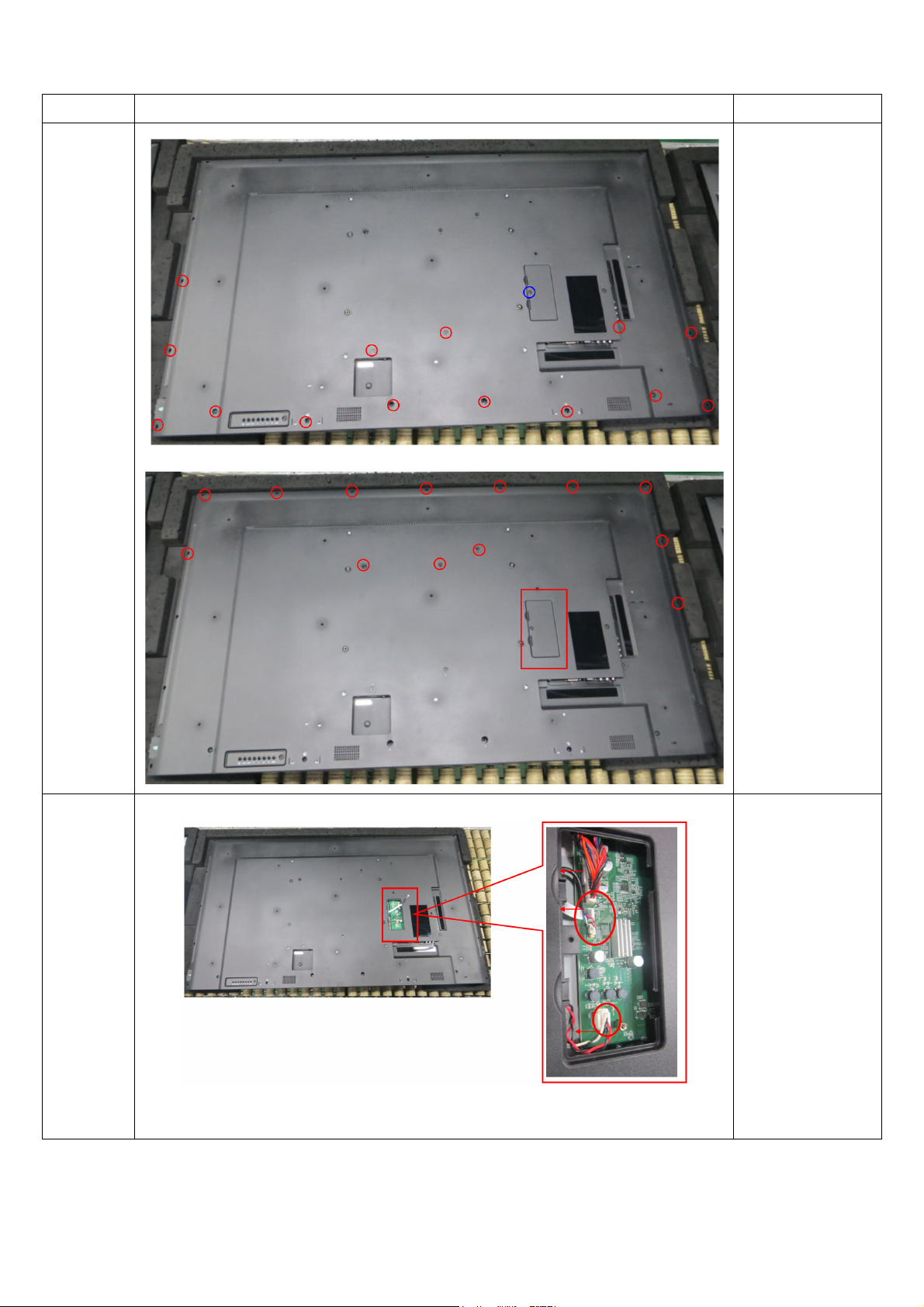
11. Mechanical Instructions
Step Figure Description
Unscrew the
screws and
Rear
remove the
cover.
COVER_SERVICE
to remove the
rear cover.
Rear
cover.
Disconnect the
connector.
57
Page 4

Remove the
tapes and all the
Boards
Main
board.
screws to remove
the main board
and power board.
Remove the
screws to remove
the main board.
58
Page 5

Panel
Disconnect the
LVDS cable to
remove tha panel.
Speaker
and IR
board
Unscrew the
screws to remove
the speaker and
IR board.
59
Page 6

Remove
Unscrew the
the Key
board
Key board.
screws to remove
the key board.
Key board.
60
Page 7

IR board
IR board
61
 Loading...