

Page 1

HP Touch Screen
Digital Signage Displays
User Guide
Page 2

© 2014 Hewlett-Packard Development
Company, L.P. The information contained
herein is subject to change without notice.
The only warranties for HP products and
services are set forth in the express
warranty statements accompanying such
products and services. Nothing herein
should be construed as constituting an
additional warranty. HP shall not be liable
for technical or editorial errors or omissions
contained herein.
This document contains proprietary
information that is protected by copyright.
No part of this document may be
photocopied, reproduced, or translated to
another language without the prior written
consent of Hewlett-Packard Company.
Microsoft and Windows are U.S. registered
trademarks of the Microsoft group of
companies.
Second Edition: May 2014
First Edition: March 2014
Document Part Number: 749853-002
Page 3

About this guide
This guide provides information on setting up the display, troubleshooting, and technical
specifications.
WARNING! Text set off in this manner indicates that failure to follow directions could result in bodily
harm or loss of life.
CAUTION: Text set off in this manner indicates that failure to follow directions could result in
damage to equipment or loss of information.
NOTE: Text set off in this manner provides important supplemental information.
iii
Page 4

iv About this guide
Page 5

Table of contents
1 Product features ................................................................................................................................................ 1
HP Digital Signage models ................................................................................................................... 1
Accessories .......................................................................................................................................... 2
Optional accessories ............................................................................................................................ 2
2 Safety and maintenance guidelines .................................................................................................................. 3
Important safety information ................................................................................................................. 3
Maintenance guidelines ........................................................................................................................ 3
Cleaning the display ............................................................................................................ 4
3 Assembling and preparing ................................................................................................................................ 5
Using the IR receiver ............................................................................................................................ 6
Portrait layout ....................................................................................................................................... 7
Using the security system .................................................................................................................... 7
Mounting the display on a wall ............................................................................................................. 7
4 Remote control .................................................................................................................................................. 9
Remote control buttons ...................................................................................................................... 10
5 Using the display ............................................................................................................................................. 12
Connecting the display to a Digital Signage media player or computer ............................................. 12
RGB/VGA connection ........................................................................................................ 13
DisplayPort connection ...................................................................................................... 14
HDMI connection ............................................................................................................... 15
Touch USB cable connection ............................................................................................ 16
IR receiver connection ....................................................................................................... 17
LAN/VOE connection ......................................................................................................... 18
Connecting the display using LAN/VOE ............................................................ 18
Connecting multiple displays to one player ....................................................... 19
Connecting multiple displays with Video Over Ethernet (VOE) ........ 19
Connecting multiple displays with Tile Mode .................................... 19
Adjusting the screen ........................................................................................................................... 22
Selecting an image mode .................................................................................................. 22
Customizing image options ................................................................................................ 22
Customizing computer display options .............................................................................. 23
Adjusting sound .................................................................................................................................. 23
v
Page 6

Selecting a sound mode .................................................................................................... 23
Customizing sound options ................................................................................................ 24
Using additional options ..................................................................................................................... 24
Using the input list ............................................................................................................. 24
Input label adjustment ........................................................................................................ 24
Selecting input labeling ..................................................................................... 24
Adjusting aspect ratio ........................................................................................................ 25
16:9 : This selection will allow you to adjust the picture horizontally, in
linear proportion, to fill the entire screen (useful for viewing 4:3 formatted
DVDs). ............................................................................................................... 26
Just Scan : This selection will allow you to view the best quality picture
without loss of the original picture in high resolution image. ............................. 26
1:1 : The original’s aspect ratio is not adjusted. (Only Display Port PC,
HDMI PC, RGB PC) .......................................................................................... 26
4:3 : This selection will allow you to view a picture with an original 4:3
aspect ratio. Black bars will appear on both the left and right of the screen. .... 27
Zoom : This selection will allow you to view the picture without any
adjustment, while filling the entire screen. However, the top and bottom of
the picture will be cropped. ............................................................................... 27
Cinema Zoom : Choose Cinema Zoom when you want to enlarge the
picture in correct proportion. Note: When enlarging or reducing the picture,
the image may become distorted. ..................................................................... 27
6 Customizing settings ....................................................................................................................................... 28
Accessing main menus ...................................................................................................................... 28
PICTURE settings .............................................................................................................. 29
Picture Mode options ........................................................................................ 30
Advanced control .............................................................................................. 30
AUDIO settings .................................................................................................................. 31
TIME settings ..................................................................................................................... 32
OPTION settings ................................................................................................................ 33
Picture ID ........................................................................................................................... 38
NETWORK settings ........................................................................................................... 39
7 Making connections ........................................................................................................................................ 40
Connecting to a Computer, HD receiver, DVD, or VCR ..................................................................... 41
DisplayPort connection ...................................................................................................... 41
HDMI connection ..............................................................................................................
Component connection ...................................................................................................... 43
Connecting to the LAN ....................................................................................................................... 44
Connecting to a USB .......................................................................................................................... 44
Daisy chain displays ........................................................................................................................... 45
. 42
vi
Page 7

8 Setting up the display for music, videos, and photos ...................................................................................... 46
Network status .................................................................................................................................... 48
Connecting USB storage devices ....................................................................................................... 48
Browsing files ..................................................................................................................................... 50
Supported file format ......................................................................................................... 51
Playing videos .................................................................................................................................... 52
Viewing photos ................................................................................................................................... 55
Listening to music ............................................................................................................................... 57
Using PIP/PBP ................................................................................................................................... 59
9 Operating the touch screen ............................................................................................................................. 61
Installing the touch software ............................................................................................................... 61
Microsoft Windows 8/ Windows 7(plug and play) .............................................................. 61
Using the touch screen ....................................................................................................................... 61
To use the touch screen on Windows 8 ............................................................................. 61
To use the touch screen on Windows 7 ............................................................................. 62
10 Troubleshooting ............................................................................................................................................ 64
Appendix A Specifications ................................................................................................................................. 67
41.92-inch (106.5-cm) model ............................................................................................................. 67
Dimensions ........................................................................................................................ 68
46.96-inch (119.3-cm) model ............................................................................................................. 69
Dimensions ........................................................................................................................ 70
Recognizing preset display resolutions .............................................................................................. 71
DTV mode .......................................................................................................................................... 72
IR codes ............................................................................................................................................. 72
Appendix B Agency regulatory notices .............................................................................................................. 74
Federal Communications Commission notice .................................................................................... 74
Modifications ...................................................................................................................... 74
Cables ................................................................................................................................ 74
Declaration of Conformity for products marked with the FCC logo (United States only) .................... 74
Canadian notice ................................................................................................................................. 75
Avis Canadien .................................................................................................................................... 75
European Union regulatory notice ...................................................................................................... 75
German ergonomics notice ................................................................................................................ 76
Japanese notice ..............................................................................................................
Korean notice ..................................................................................................................................... 76
Power cord set requirements ............................................................................................................. 76
................... 76
vii
Page 8

Japanese power cord requirements .................................................................................. 76
Product environmental notices ........................................................................................................... 77
California Perchlorate Material Notice ............................................................................... 77
Materials disposal .............................................................................................................. 77
Disposal of waste equipment by users in private households in the European Union ...... 77
Chemical substances ......................................................................................................... 77
HP recycling program ........................................................................................................ 77
Restriction of Hazardous Substances (RoHS) ................................................................... 77
India restriction of hazardous substances (RoHS) ............................................................ 78
Turkey EEE regulation ....................................................................................................... 79
Ukraine Restriction of Hazardous Substances .................................................................. 79
Taiwan Battery Disposal Warning ...................................................................................... 79
Appendix C Controlling multiple products .......................................................................................................... 80
Connecting the cable .......................................................................................................................... 80
RS-232C configurations ..................................................................................................................... 80
Communication parameter ................................................................................................................. 81
Command reference list ..................................................................................................................... 81
Transmission / Receiving protocol ..................................................................................................... 83
Transmission ..................................................................................................................... 83
Acknowledgement ............................................................................................................. 83
01. Power (Command: k a) ............................................................................... 83
02. Input Select (Command: k b) ...................................................................... 84
03. Aspect Ratio (Command: k c) ..................................................................... 84
04. Energy Saving (Command: f l) .................................................................... 85
05. Picture Mode (Command: d x) .................................................................... 85
06. Contrast (Command: k g) ............................................................................ 85
07. Brightness (Command: k h) ........................................................................ 86
08. Sharpness (Command: k k) ........................................................................ 86
09. Color Temperature (Command: k u) ........................................................... 86
10. Auto Configuration (Command: j u) ............................................................. 86
11. Balance (Command: k t) ............................................................................. 87
12. Sound Mode (Command: d y) ..................................................................... 87
13. Treble (Command: k r) ................................................................................ 87
14. Bass (Command: ks) ................................................................................... 87
15. Speaker (Command: d v) ............................................................................ 88
16. Volume Mute (Command: k e) .................................................................... 88
17. Volume Control (Command: k f) .................................................................. 88
18. Time (Command: f a) .................................................................................. 88
19. Off Timer(On/Off Timer Time (Command: f e) ............................................ 89
20. On Timer(On/Off Timer) Time (Command: f d) ........................................... 90
viii
Page 9

21. Sleep Time (Command: f f) ......................................................................... 92
22. Power On Delay (Command: f h) ................................................................ 92
23. Language (Command: f i) ........................................................................... 93
24. ISM method (Command: j p) ....................................................................... 93
25. Reset (Command: f k) ................................................................................. 93
26. Tile Mode (Command: d d) ......................................................................... 94
27. Tile ID Set (Command: d i) .......................................................................... 94
28. Tile H Position (Command: d e) .................................................................. 94
29. Tile V Position (Command: d f) ................................................................... 95
30. Tile H Size (Command: d g) ........................................................................ 95
31. Tile V Size (Command: d h) ........................................................................ 95
32. Natural Mode (In Tile Mode) (Command : d j) ............................................. 96
33. DPM Select (Command: f j) ........................................................................ 96
34. Temperature Value (Command: d n) .......................................................... 96
35. Remote Controller Lock/ Key Lock (Command: k m) .................................. 97
36. Key (Command: m c) .................................................................................. 97
37. OSD Select (Command: k l) ........................................................................ 97
38. Operating time return (Command: d l) ........................................................ 98
39. Serial No. (Command: f y) ........................................................................... 98
40. S/W Version (Command: f z) ...................................................................... 98
41. Backlight (Command: m g) .......................................................................... 98
42. Display Name (Command: v a) ................................................................... 99
43. Abnormal State (Command: k z) ................................................................. 99
44. Display Location (Command: v b) ............................................................. 100
45. Player Name (Command: v d) ................................................................... 100
46. DHCP (VOE) (Command: v e) .................................................................. 100
47. Scheduling Input Select (Command : f u) (Main Picture Input) ................. 101
48. IP Address, VOE Setup (Command: v f) ................................................... 101
49. Auto Detection (Command: f g) ................................................................. 101
50. Subnet mask, VOE Setup (Command: v g) .............................................. 102
51. IP Address, NSM Setup (Command: v k) .................................................. 102
52. Mac Address, VOE Setup (Command: v h) .............................................. 102
53. Check VOE Availability (Command: v i) .................................................... 103
54. Mac Address, NSM setup (Command: v j) ................................................ 103
55. Product Name. (Command : f v) ............................................................... 103
ix
Page 10

x
Page 11

1 Product features
HP Digital Signage models
The HP LCD digital signage displays have a wide-aspect active matrix thin-film transistor (TFT) panel.
The displays features include the following:
106.47 cm/41.92-inch diagonal model with widescreen viewable area display with 1920 x 1080
●
native resolution
119.28 cm/46.96-inch diagonal model with widescreen viewable area display with 1920 x 1080
●
native resolution
Viewing angles of 178 degrees horizontal, 178 degrees vertical
●
VGA, HDMI, DisplayPort, VOE, USB, IR, and audio inputs
●
VGA, DisplayPort, and speaker outputs
●
RS232, LAN, and IR external controls
●
External speaker option audio support
●
USB built-in player, Network utility software, video daisy-chaining using DP and VGA, group IR
●
for tiling (daisy-chain via RS232); Video-over-Ethernet (VOE)
IR spread touch technology
●
5 unambiguous points of multi-touch functionality
●
Edge-swipe gesture capability
●
Support VESA compliant mounting interface:
●
106.47 cm/41.92-inch model: 200 x 200 mm (7.87 x 7.87 in) hole pattern
◦
119.28 cm/46.96-inch model: 400 x 400 mm (15.75 x 15.75 in) hole pattern
◦
Network Sign Manager (NSM) software utility provided that allows remote, centralized
●
management and control of HP digital signage displays. Users have the ability to monitor and
send commands to all the network connected displays in a subnet from a central location such
as a data center. For more information, see the
with the display.
HP Video Over Ethernet (VOE) compatibility that provides a system of software, hardware, and
●
firmware for connecting HP Digital Signage Displays on a network with computers/media players
on the same network. For more information, see the
provided with the display.
HP Network Sign Manager User Guide
HP Video Over Ethernet User Guide
provided
HP Digital Signage models 1
Page 12

Accessories
Software and documentation disc
●
Remote control
●
Power cord
●
DisplayPort cable
●
HDMI cable
●
RGB (VGA) cable
●
USB Cable (Type A to Type B)
●
IR receiver
●
Optional accessories
Optional accessories (purchased separately) might vary depending on the model.
Stand kit
●
Speaker kit
●
Wall mount kit
●
2 Chapter 1 Product features
Page 13

2 Safety and maintenance guidelines
Important safety information
A power cord is included with the display. If another cord is used, use only a power source and
connection appropriate for this display.
WARNING! To reduce the risk of electric shock or damage to the equipment:
• Do not disable the power cord grounding feature. The grounding plug is an important safety feature.
• Plug the power cord in a grounded (earthed) outlet that is easily accessible at all times.
• Disconnect power from the product by unplugging the power cord from the electrical outlet.
For your safety, do not place anything on power cords or cables. Arrange them so that no one can
accidentally step on or trip over them. Do not pull on a cord or cable. When unplugging from the
electrical outlet, grasp the cord by the plug.
To reduce the risk of serious injury, read the
workstation, setup, posture, and health and work habits for computer users, and provides important
electrical and mechanical safety information. This guide is located on the Web at
and/or on the documentation disc, if one is included with the display.
CAUTION: For the protection of the display, as well as the media player/computer, connect all
power cords for the media player/computer and its peripheral devices (such as a display, printer,
scanner) to some form of surge protection device such as a power strip or Uninterruptible Power
Supply (UPS). Not all power strips provide surge protection; the power strips must be specifically
labeled as having this ability. Use a power strip whose manufacturer offers a Damage Replacement
Policy so you can replace the equipment, if surge protection fails.
Use the appropriate and correctly sized furniture designed to properly support your display.
WARNING! Displays that are inappropriately situated on dressers, bookcases, shelves, desks,
speakers, chests, or carts can fall over and cause personal injury.
Care should be taken to route all cords and cables connected to the display so that they cannot be
pulled, grabbed, or tripped over.
CAUTION: Do not place the device in a location where water may drip and/or splash on the device.
Do not place an object that contains water, such as a flower vase, on the device.
Maintenance guidelines
Safety and Comfort Guide
. It describes proper
www.hp.com/ergo
To enhance the performance and extend the life of the display:
Do not open the display cabinet or attempt to service this product yourself. Adjust only those
●
controls that are covered in the operating instructions. If the display is not operating properly or
has been dropped or damaged, contact an authorized HP dealer, reseller, or service provider.
Use only a power source and connection appropriate for this display, as indicated on the label/
●
back plate of the display.
Be sure the total ampere rating of the products connected to the outlet does not exceed the
●
current rating of the electrical outlet, and the total ampere rating of the products connected to the
Important safety information 3
Page 14

cord does not exceed the rating of the cord. Look on the power label to determine the ampere
rating (AMPS or A) for each device.
Install the display near an outlet that you can easily reach. Disconnect the display by grasping
●
the plug firmly and pulling it from the outlet. Never disconnect the display by pulling the cord.
Turn the display off when not in use. You can substantially increase the life expectancy of the
●
display by using a screen saver program and turning off the display when not in use.
CAUTION: Burn-in or image sticking might occur on displays which display the same static
image on the screen for prolonged periods of time. To avoid burn-in or image sticking and to
prolong the life of the display, you should activate one of the four ISM selections in the OSD,
activate a screen-saver application, periodically cycle between static information and moving
images, or turn off the display when it is not in use for prolonged periods of time.
Slots and openings in the cabinet are provided for ventilation. These openings must not be
●
blocked or covered. Never push objects of any kind into cabinet slots or other openings.
Do not drop the display or place it on an unstable surface.
●
Do not allow anything to rest on the power cord. Do not walk on the cord.
●
Keep the display in a well-ventilated area, away from excessive light, heat or moisture.
●
When removing the display base, you must lay the display face down on a soft area to prevent it
●
from getting scratched, defaced, or broken.
Cleaning the display
1. Turn off the display and unplug the power cord from the back of the unit.
2. Dust the display by wiping the screen and the cabinet with a soft, clean antistatic cloth.
3. For more difficult cleaning situations, use a 50/50 mix of water and Isopropyl alcohol.
CAUTION: Spray the cleaner onto a cloth and use the damp cloth to gently wipe the screen surface.
Never spray the cleaner directly on the screen surface. It might seep behind the bezel and damage
the electronics.
CAUTION: To clean the display screen or cabinet, do not use cleaners that contain any petroleum-
based materials such as benzene or thinner or any volatile substance. These chemicals might
damage the display.
4 Chapter 2 Safety and maintenance guidelines
Page 15
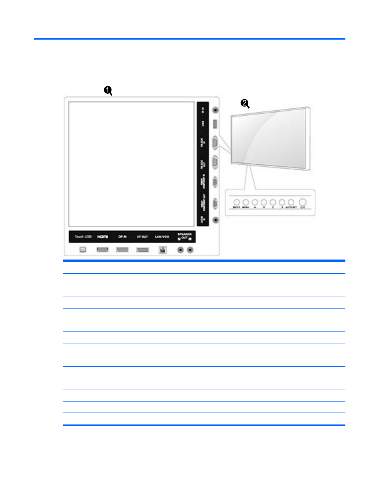
3 Assembling and preparing
Item Connection panel Description
(1) Touch USB Connects a touch USB cable from the computer to the display.
HDMI Connects voice or audio input cable.
DP IN Connects DisplayPort in cable to the display.
DP OUT Connects DisplayPort out cable to the display.
LAN/VOE Connects a local area network cable.
SPEAKER OUT Connects optional external speakers to the display.
AUDIO IN Connects an audio cable to the display.
RGB/AV COMPONENT OUT Connects an RGB/AV component out cable to the display.
RGB/AV COMPONENT IN Connects an RGB/AV component in cable to the display.
RS-232C OUT Connects an RS-232C out cable to the display.
RS-232C IN Connects an RS-232C in cable to the display.
USB Connects a USB cable to the display.
IR IN Connects an IR cable to the display.
5
Page 16
Item Screen marks Description
(2) INPUT Changes the input source.
MENU Accesses the main menus, or saves your input and exits the menus.
AUTO/SET Displays the current signal and mode. Press this button to adjust the screen automatically (RGB
Moves the selection up and down.
Adjusts the volume level.
mode only).
Turns the power on or off.
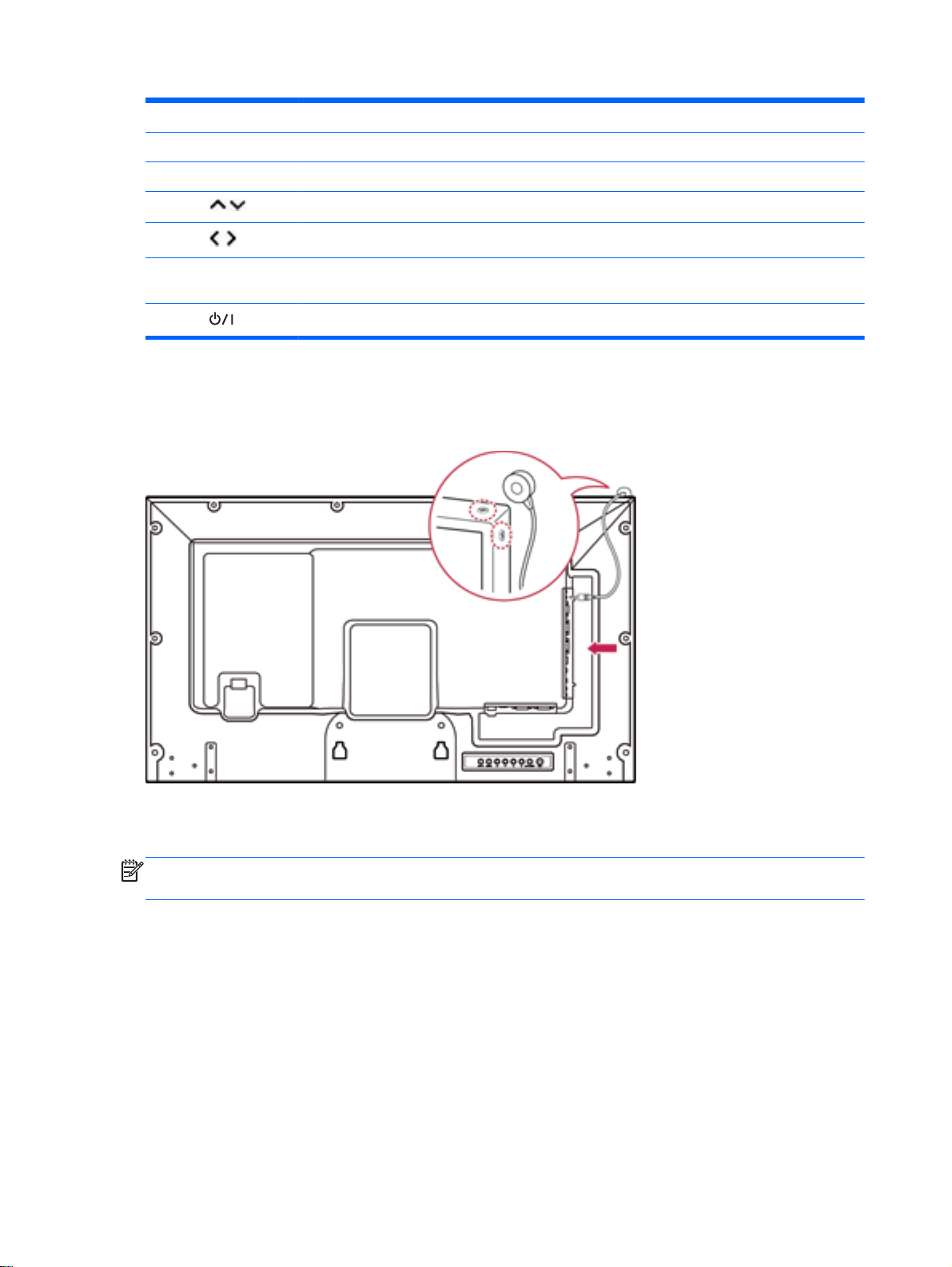
Using the IR receiver
This allows a remote control sensor to be placed in a custom location.
The IR magnetic IR receiver must be placed on the front or side of the display. The IR receiver should
be in the remote control line of sight. The magnetic IR receiver must be placed on the screw location
(display frame).
NOTE: The IR receiver is made with a magnet. If it is attached to the side or the bottom of the
product, external shocks may cause the IR receiver to fall.
6 Chapter 3 Assembling and preparing
Page 17
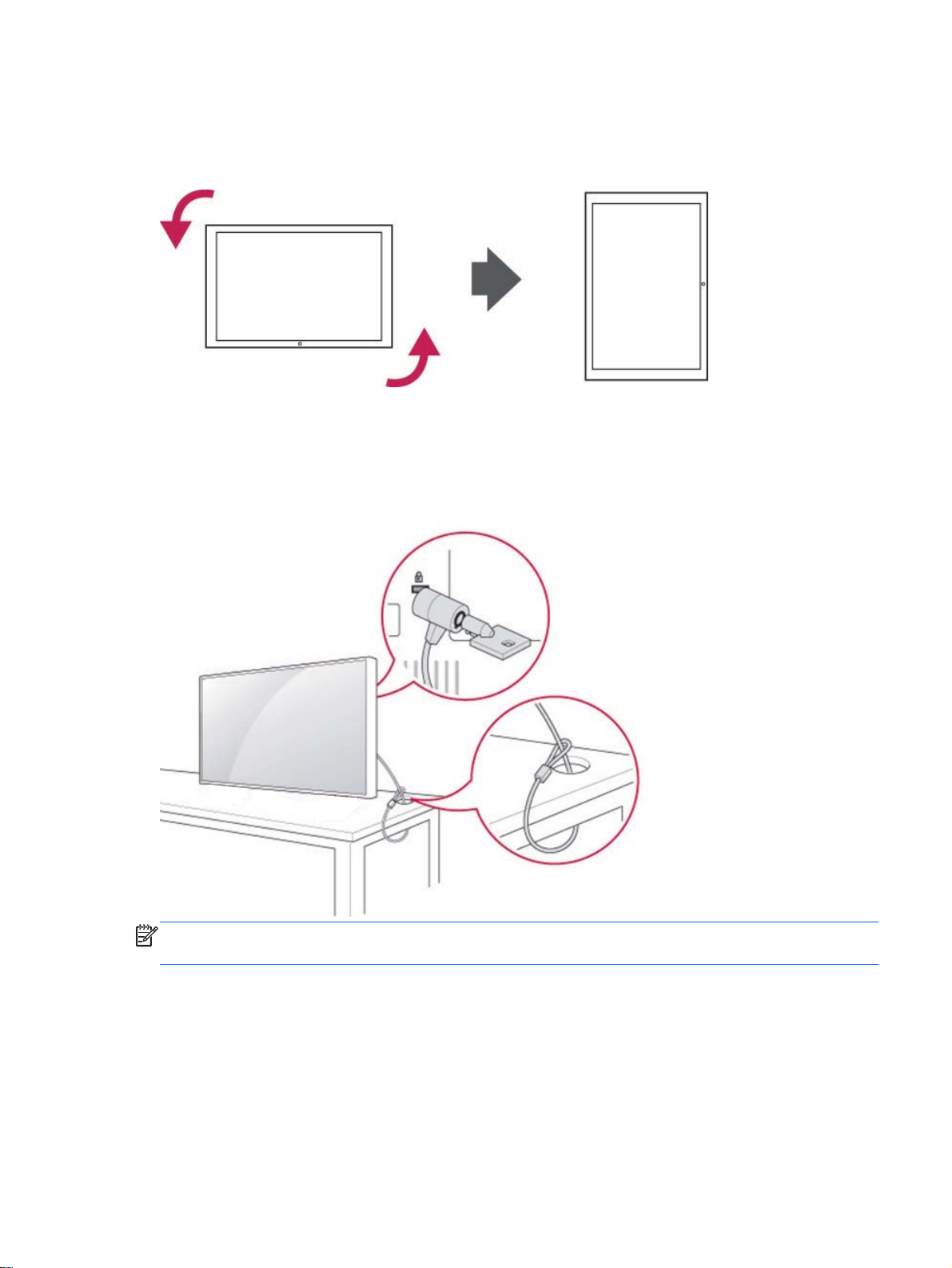
Portrait layout
To install in portrait orientation, rotate the display counterclockwise 90 degrees when looking at it
from the front.
Using the security system
The security system connector is located at the back of the display.
Connect the security system cable between the display and a table.
NOTE: The security system is separately purchased. You can obtain additional accessories from
most electronics stores.
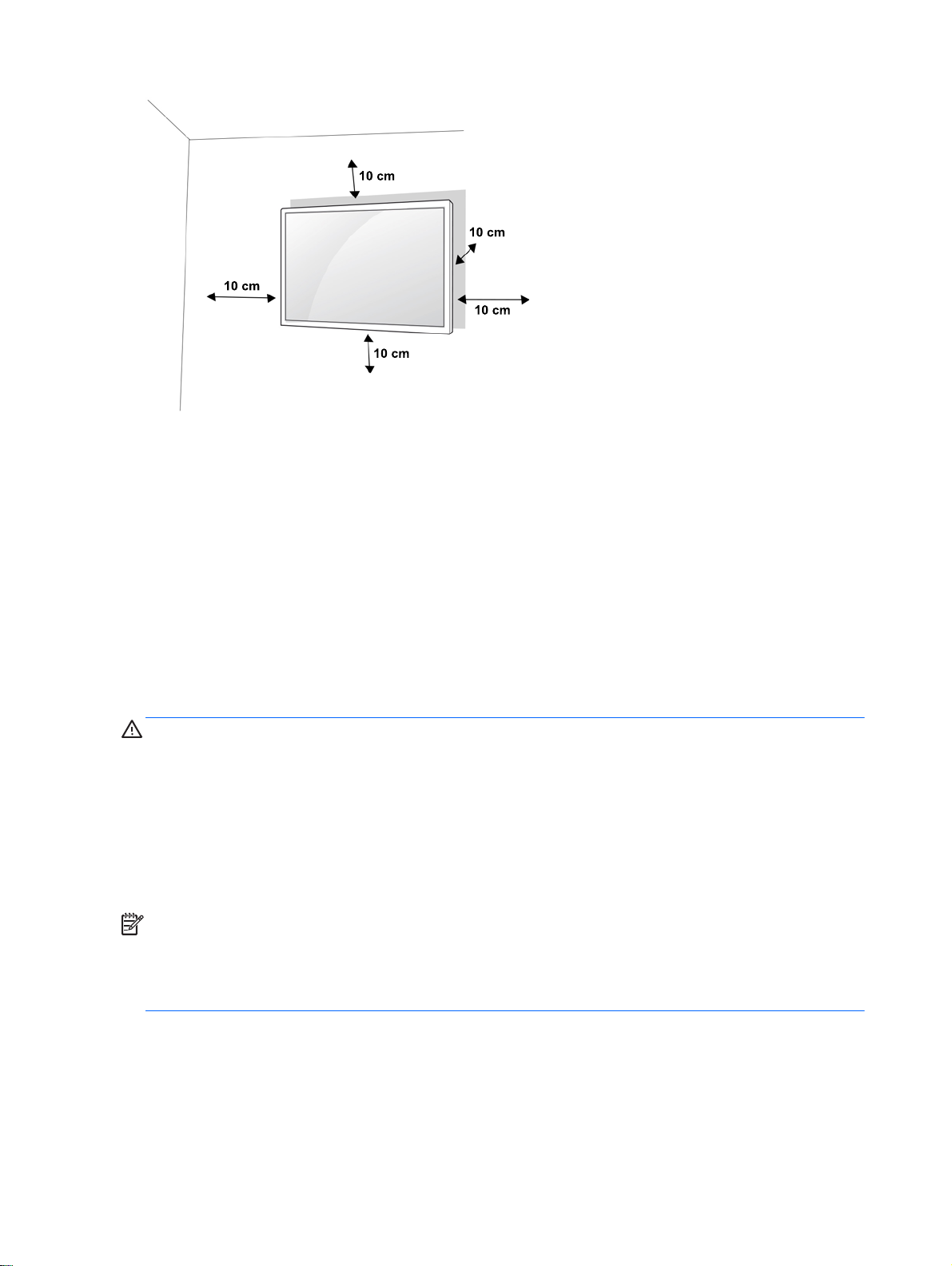
Mounting the display on a wall
For proper ventilation, allow a clearance of 10 cm on each side and from the wall. Detailed installation
instructions are available from the manufacturer of the mounting equipment.
Portrait layout 7
Page 18
If you intend to mount the display to a wall, attach a wall mounting interface (optional parts) to the
back of the set.
When you install the display using a wall mounting interface (optional parts), attach it carefully so it
will not fall.
1. Use a wall mount and screws in accordance with VESA Standards.
If you use screws longer than the VESA standard, the display might be damaged internally.
If you use improper screws, the product might be damaged and drop from mounted position. In
this case, HP is not responsible for damage.
2. Use VESA standard as follows:
785 mm (31 inch) or greater
●
Fastening screw: Diameter 6.0 mm x Pitch 1.0 mm x Length 10 mm
●
CAUTION: Disconnect the power cord first, and then move or install the display. Otherwise electric
shock may occur.
If you install the display on a ceiling or slanted wall, it may fall and result in severe injury.
Use an authorized HP wall mount and contact the local dealer or qualified personnel.
Do not over tighten the screws as this may cause damage to the display and void your warranty.
Use the screws and wall mounts that meet the VESA standard. Any damages or injuries by misuse or
using an improper accessory are not covered by the warranty.
NOTE: The wall mount bracket is optional. You can obtain additional accessories from your local
dealer.
The length of screws may differ depending on the wall mount. Be sure to use the proper length.
For more information, refer to the manufacturer’s instructions supplied with the wall mount.
8 Chapter 3 Assembling and preparing
Page 19
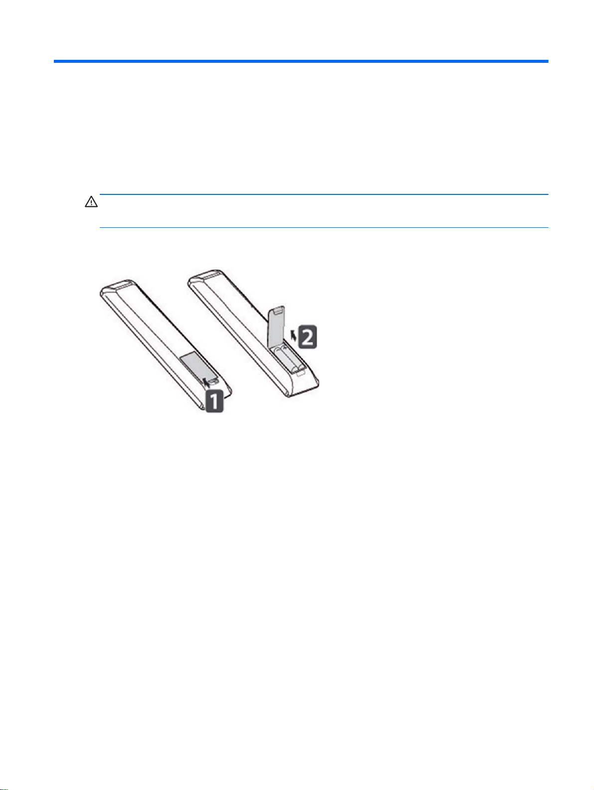
4 Remote control
The remote control ships with batteries.
To replace batteries, open the battery cover, replace batteries (1.5 V AAA) matching (+) and (-) ends
to the label inside the compartment, and close the battery cover. To remove the batteries, perform the
installation actions in reverse.
CAUTION: Do not mix old and new batteries, as this may damage the remote control.
Make sure to point the remote control to the remote control sensor on the display.
9
Page 20
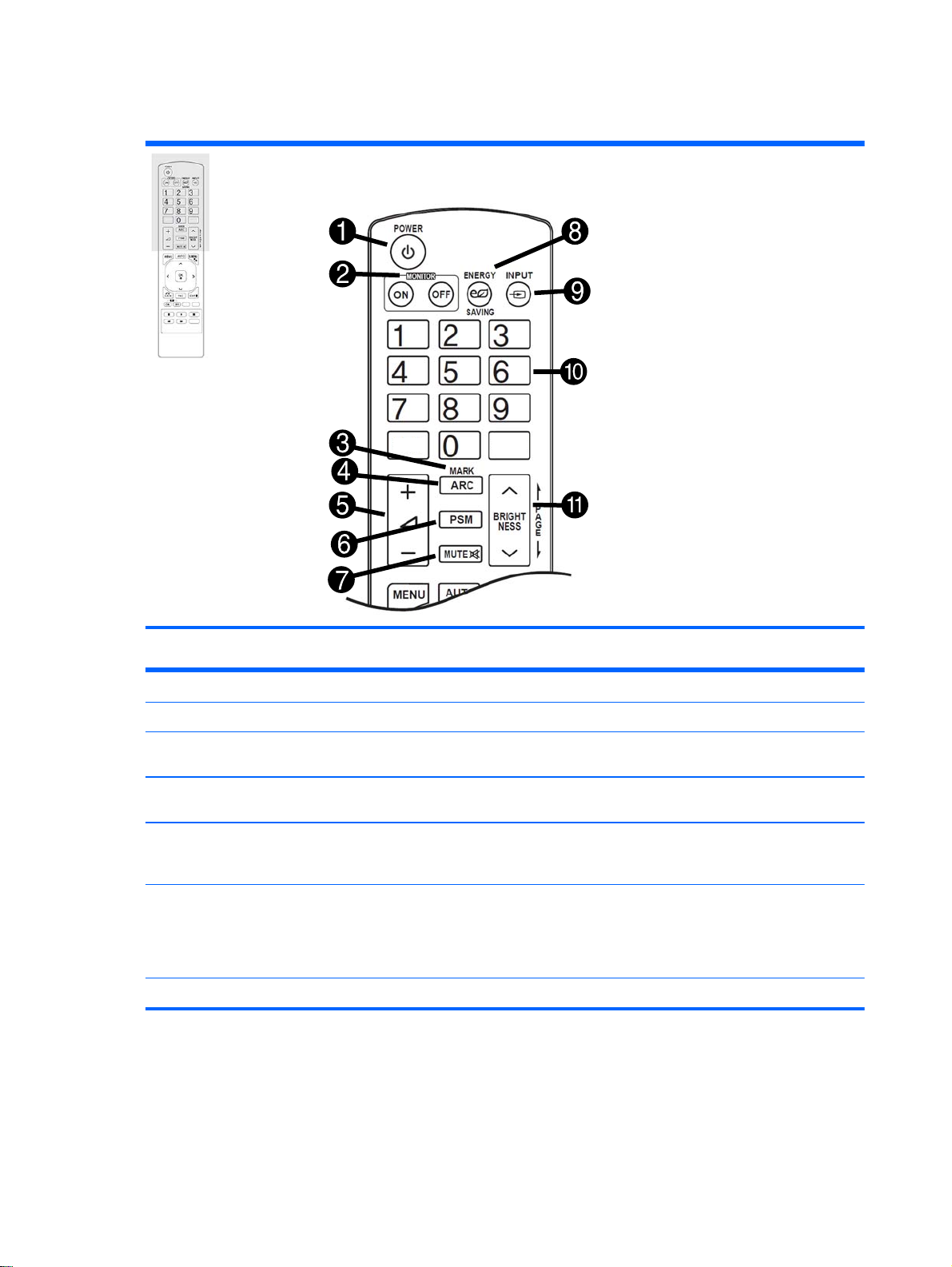
Remote control buttons
Item Button Function Item Button Function
(1) Power Turns the display on or off. (7) MUTE Mutes all sound.
(2) MONITOR
ON/OFF
(3) MARK Selects a specific file in USB
(4) ARC Selects the aspect ratio. (10) Number and
(5) Volume up/
down
(6) PSM Selects Picture Status Mode.
Turns off the display then turns
it back on.
mode.
Adjusts the volume level. (11) BRIGHTNESS
(8) ENERGY
SAVING
(9) INPUT Selects Input mode.
alphabet
buttons
key
Adjusts the brightness on the screen
to reduce energy consumption.
Enters numerical or alphabetical
characters depending on the setting.
Adjust the brightness by pressing
the Up and Down buttons on the
remote control. In USB mode, the
OSD menu has the Page function to
move to the next file list.
10 Chapter 4 Remote control
Page 21
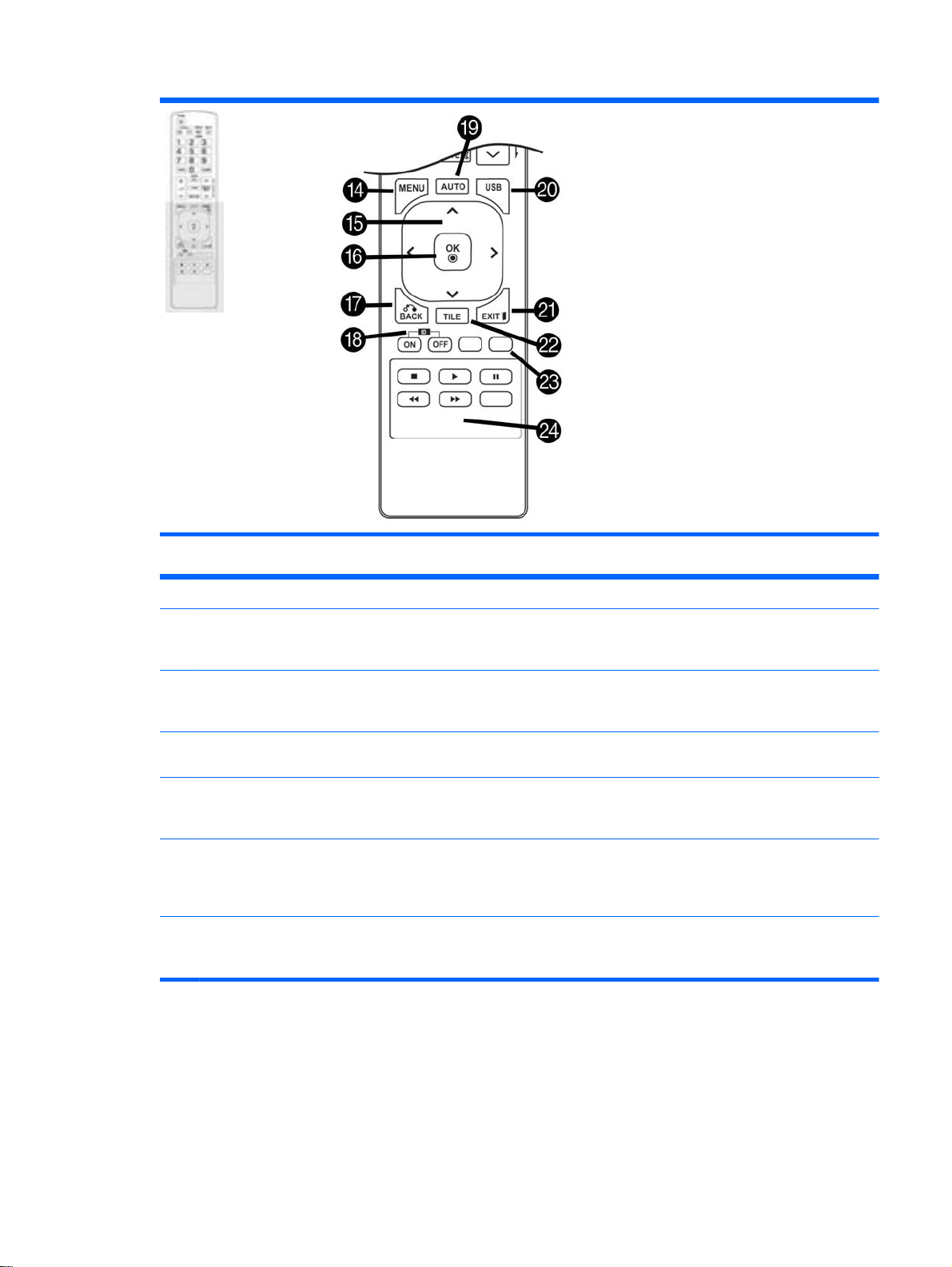
Item Button Function Item Button Function
(14) MENU Accesses the main menus or
saves your input and exits
menus.
(15) Navigation
buttons
(16) OK Selects menus or options and
(17) BACK Allows the user to move back
(18) ID ON/OFF When the number of Picture ID
(19) AUTO Automatically adjusts picture
Scrolls through menus or
options.
confirms your input.
one step in user interaction
function.
is equal to Set ID, you can
control the display you want in
multi display mode.
position and minimizes image
instability (RGB input only).
(20) USB Selects USB menu to control the HP
Media Sign Player.
(21) EXIT Clears all on-screen displays and
returns to display viewing from any
menu.
(22) TILE Selects Tile mode.
(23) Input label
(blue button)
(24) USB Menu
control buttons
Input label may be adjusted to either
PC or DTV.
Control media playback.
Remote control buttons 11
Page 22
5 Using the display
Connecting the display to a Digital Signage media player or computer
Your display supports the Plug and Play feature. In Plug and Play, a computer will have a built-in
driver for the display, no extra software is needed.
NOTE: It is recommended you use a DisplayPort connection for the best image quality.
Use a shielded signal interface cable, such as D-sub 15 pin signal cable and HDMI cable, with a
ferrite core to maintain standard compliance for the product.
If you turn the display on when the set is cold, the screen may flicker. This is normal.
Some red, green, or blue spots may appear on the screen. This is normal.
If you use a cable longer than the D-sub 15 pin signal cable provided, certain images may appear
blurry.
Connect the signal input cable and tighten it by turning the screws clockwise.
CAUTION: Do not press the screen with your finger for a long time as this may result in temporary
distortion on the screen.
Avoid displaying a fixed image on the screen for a long period of time to prevent image burn. Use a
screen saver if possible.
12 Chapter 5 Using the display
Page 23
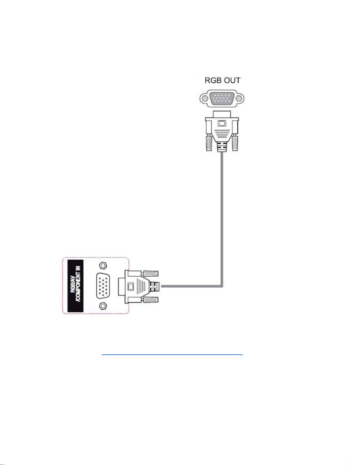
RGB/VGA connection
Transmits an analog video signal from your computer to the display. Connect the computer and the
display with a standard RGB/VGA cable as shown in the following illustration. Select RGB/VGA IN
connector on display. The audio in cable is not provided with display.
To connect this display to another display via RGB/VGA (daisy chain), plug one end of a second
RGB/VGA cable into the Output RGB/VGA connector on the display and plug the other end of RGB/
VGA cable into the Input RGB/VGA connector on the next display in chain. RGB/VGA connection can
have multiple displays (up to 6) connected to a single player/computer using the tile mode. For more
information, see
Connecting multiple displays to one player on page 19.
Connecting the display to a Digital Signage media player or computer 13
Page 24
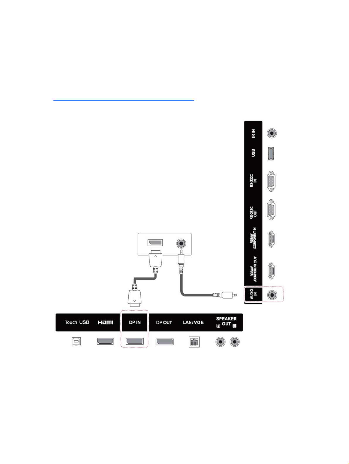
DisplayPort connection
Transmits digital video signal from your computer to the display. Connect the computer and the
display with a DisplayPort cable as shown the following illustration. Select Display IN. The audio in
cable is not provided with the display.
If you will be connecting this display to another display via DisplayPort (daisy chain), plug one end of
a second DisplayPort cable into the DP-OUT connector on the display and plug the other end of
DisplayPort cable into the DP-IN connector on the next display in chain. For more information, see
Connecting multiple displays to one player on page 19.
Back of the product
14 Chapter 5 Using the display
Page 25
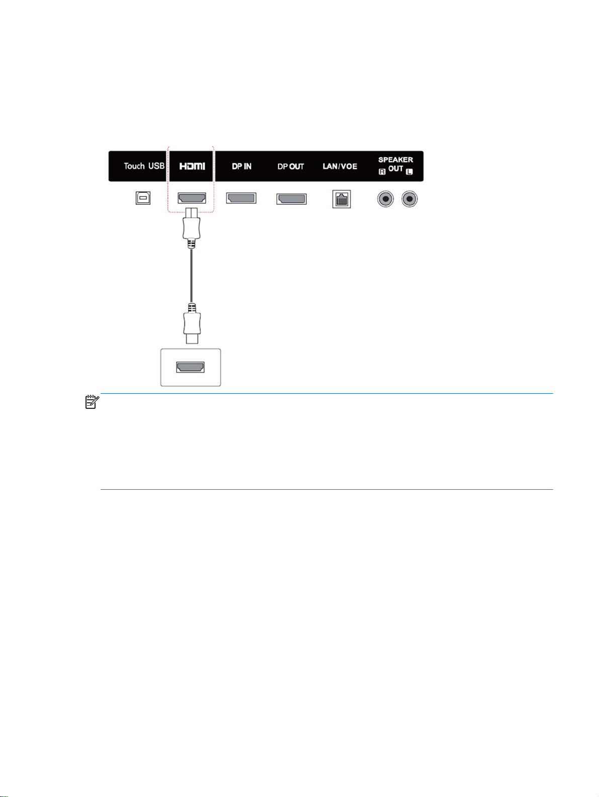
HDMI connection
Transmits the digital video and audio signals from your computer to the display. Connect the
computer and the display with an HDMI cable as shown in the following illustration. Select HDMI
input.
Back of the product
NOTE: Use a high Speed HDMI cable. High speed HDMI cables can handle definition beyond
1080p.
Check the computer environment if you cannot hear audio in HDMI mode. Some computers require
you to manually change the default audio output to HDMI.
If you want to use HDMI-PC mode, you must set the input label to PC mode.
When HDMI PC is used, a compatibility problem might occur.
Connecting the display to a Digital Signage media player or computer 15
Page 26
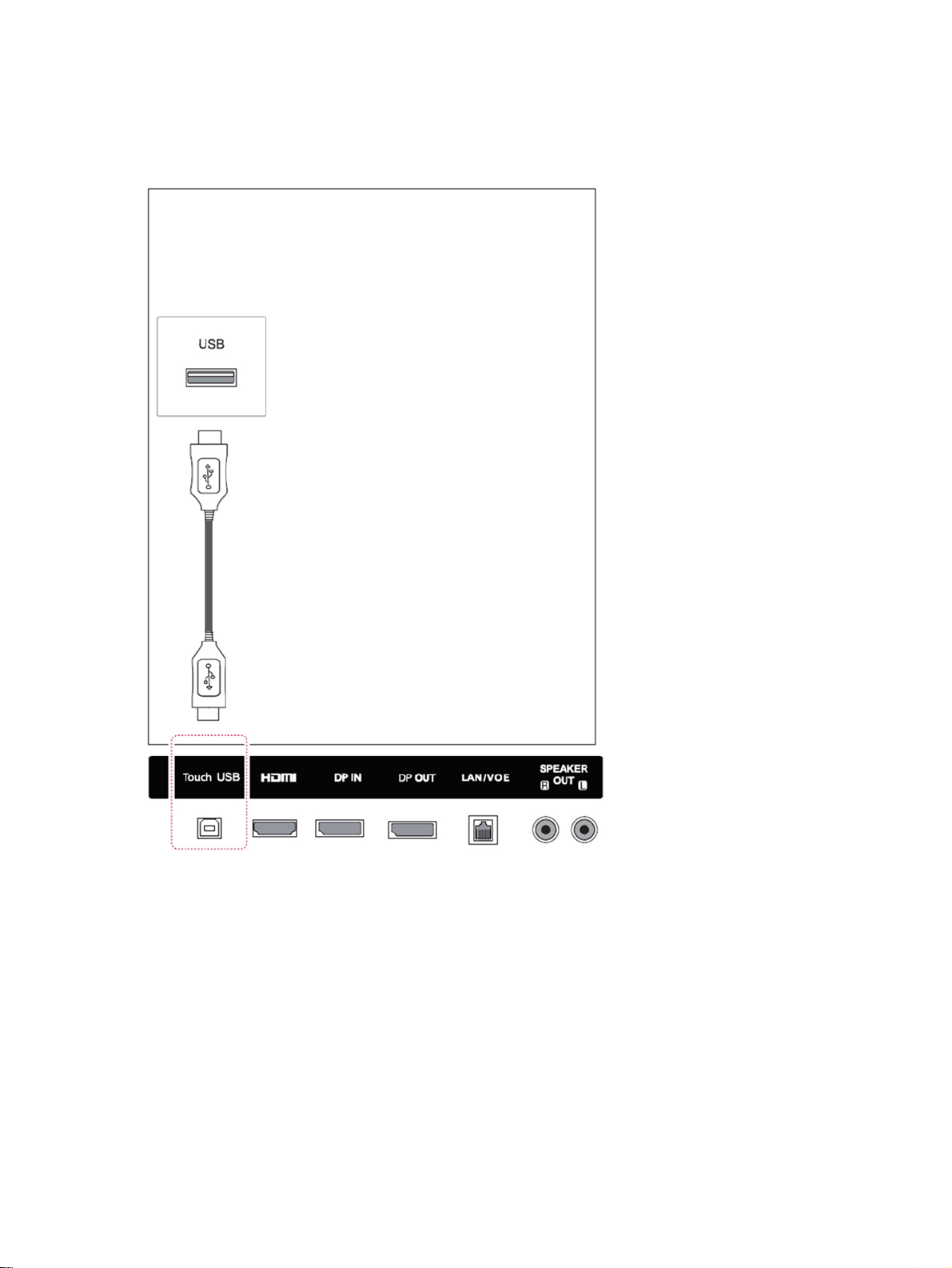
Touch USB cable connection
Connect one end of the provided USB cable to the USB upstream connector (type B) on the rear of
the display, and connect the other end to a USB connector on the computer (type A).
16 Chapter 5 Using the display
Page 27
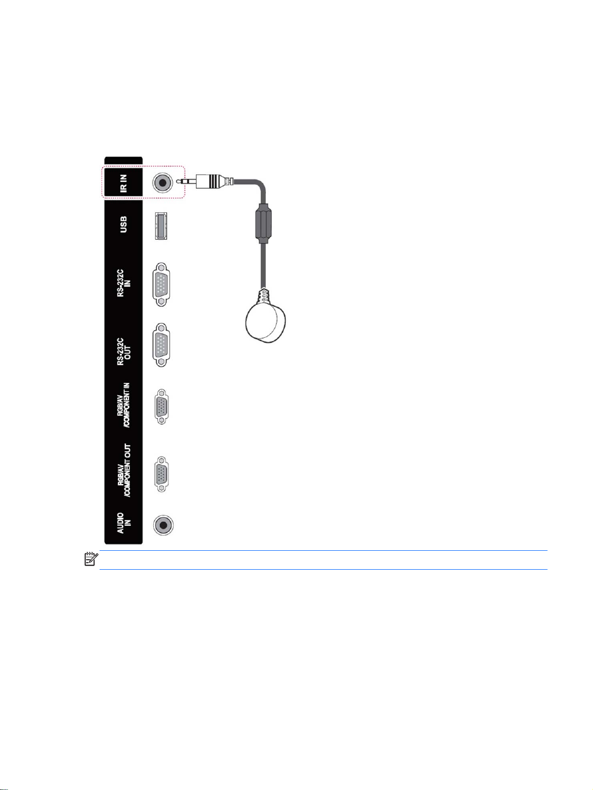
IR receiver connection
Allows the use of a wired remote or IR receiver extension. The IR cable is provided with the display.
IR magnetic receiver must be placed on the front or side of monitor (frame screw location). The IR
receiver should be in the remote line of sight.
Back of the product
NOTE: Make sure the power cable is disconnected.
Connecting the display to a Digital Signage media player or computer 17
Page 28
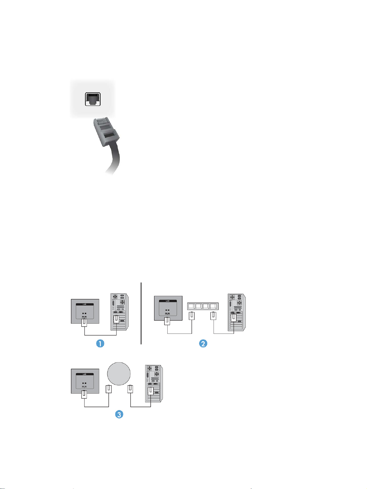
LAN/VOE connection
Connecting the display using LAN/VOE
To connect the display to a network, plug your CAT-5 network cable into the Ethernet port.
▲
The Ethernet cable from the display can connect to a media player/computer, a router (switch),
or an Intranet. A network connection enables the use of the Video Over Ethernet software to
assign a media player to drive the display. The connection also allows the HP Network Sign
Manager program, running on a networked media player/computer, to send command data.
Connect the Ethernet cable using one of the following connections:
Computer Direct Connection—Connect the LAN cable to the LAN port on the display and to
●
the LAN port on the media player/computer (1).
Router—Connect the LAN cable to the LAN port on the display and to a LAN port on the
●
router (2).
Intranet—Connect the LAN cable to the LAN port on the display and to the Intranet network
●
via an access point (3).
18 Chapter 5 Using the display
Page 29
Connecting multiple displays to one player
Multiple displays may be connected to a single media player/computer two different ways, using
Video Over Ethernet or using Tile Mode with VGA or DisplayPort video inputs.
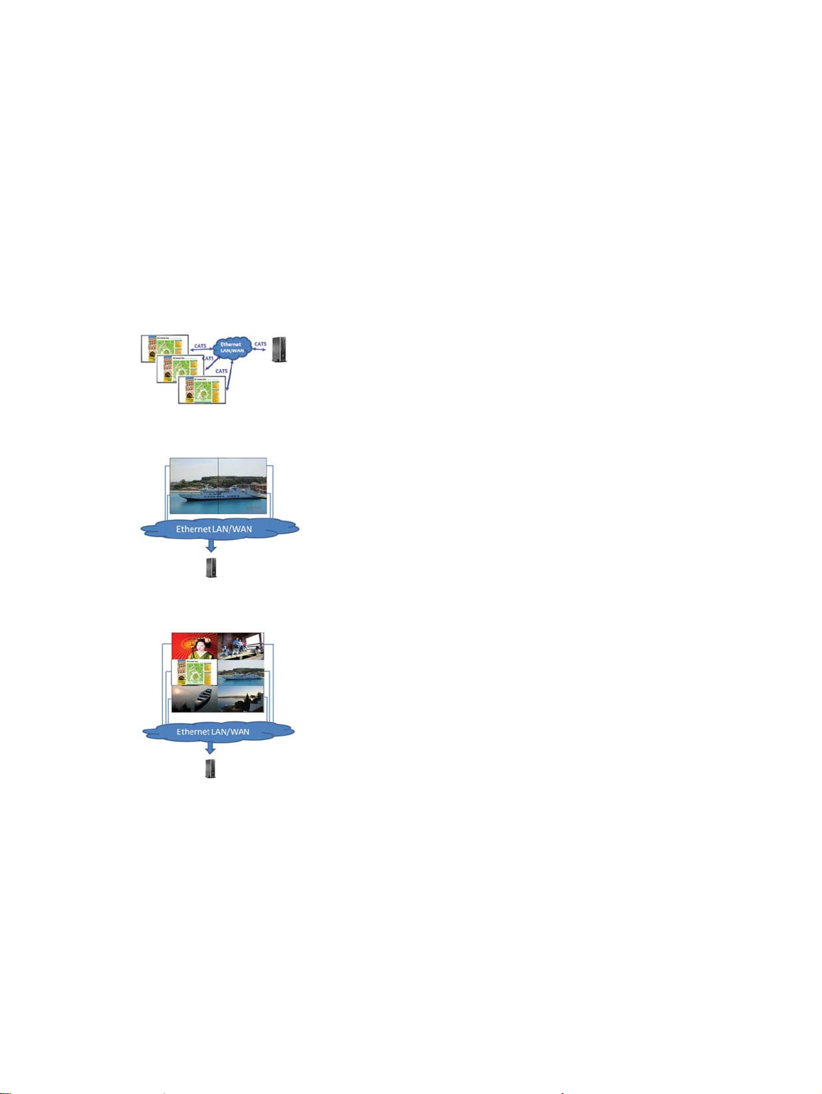
Connecting multiple displays with Video Over Ethernet (VOE)
To connect multiple displays to a single media player/computer, each display must be connected to
the same sub-network as the media player/computer. The input source of each display must be set to
VOE. With VOE, displays are connected to media players/computer by establishing an association
between the media player/computer and one or more displays on the network with the VOE software
that runs in the media player/computer. Up to 4 displays may be associated with a single media
player/computer (See the
displays are associated with a single media player/computer, the displays may be mirrored (a single
desktop image displays on all the displays simultaneously).
The image may be extended across all the displays simultaneously using the View Span “Display
Resolution” dialog box.
VOE Users Guide
provided with the display for more detail). When multiple
The displays may be treated by an application as though there were up to 4 individual displays
connected to 4 graphic adaptor heads on the media player/computer.
The association of up to 4 displays is the technical limit, and depending upon the complexity of the
desktop image to be displayed (playing flash, or streaming video), the number of displays which can
be associated with acceptable video performance may be less than 4 (See the
User Guide
Connecting multiple displays with Tile Mode
The recommended cable routing for daisy chain in Tile Mode is to start with the upper left display and
connect across the upper tier of displays going from left to right to the last display in that tier. Then
cable from the upper right display to the display just below it and connect across from right to left to
the last display on the left. Continue this back and forth, top to bottom cable route for all the tiers in
the wall as indicated in the next figure.
for more detail).
Video Over Ethernet
Connecting the display to a Digital Signage media player or computer 19
Page 30
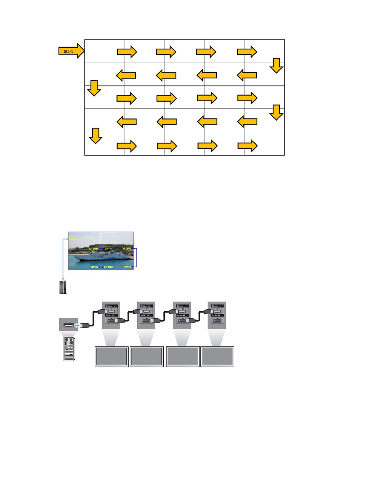
Multiple displays (up to 25 for DP and 6 for RGB/VGA) may be connected to a single media player/
computer using Tile Mode. Multiple displays in Tile Mode are only supported with either DisplayPort
or VGA video input sources. When connecting the multiple displays, the media player/computer is
connected to the first display only with either a DisplayPort or VGA connection. All the subsequent
displays are connected to each other via daisy chain using either the DP OUT connector from one
display to the DP IN connector of the next display, or using the VGA OUT connector from one display
to the VGA IN connector of the next display. All displays must be connected with the same video
source, either DisplayPort or VGA. When using Tile mode to connect multiple displays, only one
desktop image may be displayed across all the tiled displays.
20 Chapter 5 Using the display
Page 31

To remotely manage and control multiple displays in Tile Mode when using either VGA or DisplayPort
video source, either a RS-232 or Network connection may be used with the HP Network Sign
Manager.
If using the RS-232 interface, the displays must be daisy chained with RS-232 cables. Attach one end
of a RS-232 cable to the RS-232 Input connector of the first display and connect to the serial
connector of the media player/computer. Then attach one end of an RS-232 cable to the RS-232
Output connector and the other end to the RS-232 Input connector of the next display and continue to
connect the RS-232 cables between each display in the tiled matrix.
If using a Network connection, just attach each display to a network hub or access point using a
CAT-5 cable, and HP Network Sign Manager will locate each network attached display. The HP
Network Sign Manager will allow users to select any display or assigned group of displays to manage
and control. If the display is already attached to the network for VOE, there is no further action
required. The HP Network Sign Manager will detect the displays via its search function (See the
Network Sign Manager Users Guide
provided with the display for more details).
HP
Multiple displays may also be controlled and managed with the IR Remote Control.
NOTE: The number of displays that can be connected by daisy chain to one media player/computer
might vary depending on the signal status and cable loss. If the signal status is good, 25 displays for
DP and 6 displays for RGB/VGA in a daisy chain from one media player/computer.
If you are going to play video that is copy protected with High-bandwidth Digital Content Protection
(HDCP), you must use DisplayPort as the video source, and you are limited to a maximum of six
displays in the daisy chain which can support HDCP.
When using Tile Mode, the display ID can be set in the display OSD with the IR Remote Control, the
display control panel, or for Network attached displays, the display ID can be set with the HP Network
Sign Manager software (See the
more details).
Connecting the display to a Digital Signage media player or computer 21
HP Network Sign Manager User Guide
provided with the display for
Page 32

Adjusting the screen
Selecting an image mode
Display images in its optimized settings by selecting one of the preset image modes.
1. Press MENU to access the main menus.
2. Press the Navigation buttons to scroll to PICTURE and press OK.
3. Press the Navigation buttons to scroll to Picture Mode and press OK.
4. Press the Navigation buttons to scroll to an image mode you want and press OK.
Option Description
Vivid Adjusts the video image by enhancing the contrast, brightness, Color, and sharpness.
Standard Adjusts the image for the normal environment.
Cinema Optimizes the video image for a cinematic look to enjoy videos.
Sport Optimizes the video image for high and dynamic actions by emphasizing primary Colors such as
white, grass, or sky blue.
Game Optimizes the video image to enjoy dynamic image when playing a game.
5. When you are finished, press EXIT. When you return to the previous menu, press BACK.
Customizing image options
Customize basic and advanced options of each image mode for the best screen performance.
1. Press MENU to access the main menus.
2. Press the Navigation buttons to scroll to PICTURE and press OK.
3. Press the Navigation buttons to scroll to Picture Mode and press OK.
4. Press the Navigation buttons to scroll to an image mode you want and press OK.
5. Select and adjust the following options, and then press OK.
Option Description
Backlight Adjusts the brightness of the screen by controlling the LED backlight. If you decrease the brightness
level, the screen becomes darker and the power consumption will be reduced without any video
signal loss.
Contrast Increases or decreases the gradient of the video signal. You may use Contrast when the bright part
of the picture is saturated.
Brightness Adjusts the base level of the signal in the picture. You may use Brightness when the dark part of the
picture is saturated.
Sharpness Adjusts the level of crispness in the edges between the light and dark areas of the picture. The lower
the level, the softer the image.
Color Adjusts intensity of all colors.
Tint Adjusts the balance between red and green levels.
Color temp. Set to warm to enhance hotter Colors such as red, or set to cool to make picture bluish.
22 Chapter 5 Using the display
Page 33

Advanced
Control
Picture Reset Restores the options to the default setting.
Customizes the advanced options.
6. When you are finished, press EXIT. When you return to the previous menu, press BACK.
Customizing computer display options
Customize options of each image mode for the best image quality.
This function works in the following mode: RGB[PC] mode.
1. Press MENU to access the main menus.
2. Press the Navigation buttons to scroll to PICTURE and press OK.
3. Press the Navigation buttons to scroll to Screen and press OK.
4. Select and adjust following options, and then press OK.
Option Description
Resolution Selects a proper resolution. See
Auto Config. Sets to adjust the screen position, clock, and phase automatically. The displayed image may
Position/ Size/Phase Adjusts the options when the picture is not clear, especially when characters are shaky, after
Reset Restores the options to the default setting.
5. When you are finished, press EXIT. When you return to the previous menu, press BACK.
Adjusting sound
Selecting a sound mode
Play the sound in its optimized settings by selecting one of the preset sound modes.
1. Press MENU to access the main menus.
2. Press the Navigation buttons to scroll to AUDIO and press OK.
3. Press the Navigation buttons to scroll to Sound Mode and press OK.
4. Press the Navigation buttons to scroll to an image mode you want and press OK.
Mode Description
Customizing settings on page 28.
be unstable for a few seconds while the configuration is in progress.
the auto configuration.
Standard Select when you want standard quality sound.
Music Select when you listen to music.
Cinema Select when you watch videos.
Sport Select when you watch sports events.
Game Select when you want to enjoy dynamic sound when playing a game.
5. When you are finished, press EXIT. When you return to the previous menu, press BACK.
Adjusting sound 23
Page 34

Customizing sound options
Customize options of each sound mode for the best sound quality.
1. Press MENU to access the main menus.
2. Press the Navigation buttons to scroll to AUDIO and press OK.
3. Press the Navigation buttons to scroll to Sound Mode and press OK.
4. Press the Navigation buttons to scroll to an image mode you want and press OK.
5. Select and adjust following options, and then press OK.
Option Description
Infinite sound Provides 5.1 channel stereo sound from two speakers.
Treble Controls the dominant sounds in the output. When you turn up the treble, it will increase the
output to the higher frequency range.
Bass Makes the output sound softer. If the bass is increased, the frequency of the output also
increases.
Reset Resets the sound mode to the default setting.
6. When you are finished, press EXIT. When you return to the previous menu, press BACK.
Using additional options
Using the input list
Selecting an input source
1. Press INPUT to access the input source list.
2. Press the Navigation buttons to scroll to one of the input sources and press OK.
Input Source Description
AV Watch the contents in a DVD or other external devices, or through a digital set-top box.
Component Watch the contents in a DVD or other external devices, or through a digital set-top box.
RGB View a computer display on the screen.
HDMI Watch contents in a computer, DVD, or digital set-top box or other high definition devices.
DisplayPort Watch contents in a computer, DVD or digital set-top box other high definition devices.
VOE Watch contents through the Ethernet port.
USB Plays the multimedia files saved in the USB.
Input label adjustment
Selecting input labeling
The digital inputs may be set to PC or DTV input labels (HDMI, DisplayPort or VOE). The PC input
label allows limited aspect ratio (16:9, 1:1 or 4:3). The DTV input label provides adjustment
capabilities for zoom, Just Scan, sharpness, color, and tint control.
24 Chapter 5 Using the display
Page 35

NOTE: Touch accuracy is optimized by using full screen mode. The monitor should be adjusted to
16:9 aspect ratio. Also, the user may adjust the aspect ratio to Just Scan if the input label is set to
DTV (DisplayPort, HDMI, or VOE).
The digital input labeling procedure (HDMI, DisplayPort or VOE inputs only).
1. Press the INPUT button to access the input source list.
2. Press the blue button to access the input label.
3. Press the navigation buttons to scroll to one of the input sources
4. Press the navigation buttons to scroll to an input label name, and then press OK.
Adjusting aspect ratio
CAUTION: All models are not suitable for applications that exhibit static, stationary, or fixed images.
Static images may cause image retention damage that may appear as stains or watermarks on the
screen. The warranty does not cover displays that are in use for applications that exhibit static,
stationary, or fixed images for long periods or for 24-hours per day that result in image retention
damage. To avoid image retention damage, turn off the display when it is not in use or use a power
management setting, if supported by your system, to turn off the display when the system is idle.
NOTE: You can also change the image size by accessing the main menus.
Just Scan mode operates when a video signal has resolution of 720p or higher.
The aspect ratio modes available for your selection depend on the current input source. Use the
following table to determine which mode is available for your display.
MODE Component RGB
ARC DTV PC DTV PC
16:9 o o o o o o
Just Scan o x o o o o
1:1 x o x o x o
4:3 o o o o o o
Zoom o x oxox
Cinema Zoom o x oxox
PC
DisplayPort HDMI
Using additional options 25
Page 36

16:9 : This selection will allow you to adjust the picture horizontally, in linear proportion, to fill
the entire screen (useful for viewing 4:3 formatted DVDs).
Just Scan : This selection will allow you to view the best quality picture without loss of the
original picture in high resolution image.
NOTE: If there is noise in original picture, you can see the noise at the edge.
1:1 : The original’s aspect ratio is not adjusted. (Only Display Port PC, HDMI PC, RGB PC)
26 Chapter 5 Using the display
Page 37

4:3 : This selection will allow you to view a picture with an original 4:3 aspect ratio. Black bars
will appear on both the left and right of the screen.
Zoom : This selection will allow you to view the picture without any adjustment, while filling
the entire screen. However, the top and bottom of the picture will be cropped.
Cinema Zoom : Choose Cinema Zoom when you want to enlarge the picture in correct
proportion. Note: When enlarging or reducing the picture, the image may become distorted.
Using additional options 27
Page 38

6 Customizing settings
Accessing main menus
1. Press MENU to access the main menus.
2. Press the Navigation buttons to scroll to one of the following menus and press OK.
3. Press the Navigation buttons to scroll to the setting or option you want and press OK.
4. When you are finished, press EXIT. When you return to the previous menu, press BACK.
Item Function Description
(1) PICTURE Adjusts the image size, quality, or effect
(2) AUDIO Adjusts the sound quality, effect, or volume level.
(3) TIME Sets the time, date, or Timer feature.
(4) OPTION Customizes the general settings
(5) NETWORK Sets up the network.
(6) MY MEDIA Display and play video, photo and music content stored on your USB.
28 Chapter 6 Customizing settings
Page 39

PICTURE settings
1. Press MENU to access the main menus.
2. Press the Navigation buttons to scroll to PICTURE and press OK.
3. Press the Navigation buttons to scroll to the setting or option you want and press OK.
4. When you are finished, press EXIT. When you return to the previous menu, press BACK.
Setting Description
Aspect Ratio Changes the image size to view images at its optimal size.
Energy Saving Sets to automatically adjust the screen brightness corresponding to the surroundings.
Level
Off: Disables Energy Saving function.
Minimum/Medium/Maximum: Selects the brightness level of the LED backlight.
Screen Off: The screen turns off in 3 seconds.
Smart Energy
Saving
Picture Mode Selects one of the preset image modes or customizes options in each mode for the best display screen
SCREEN (In RGB
Mode Only)
Adjusts the LED backlight and contrast depending on the screen brightness.
Level
Off: Disables the Smart Energy Saving function.
On: Enables the Smart Energy Saving function to save power consumption as much as the value set in
the smart energy saving rate.
performance. You are also able to customize advanced options of each mode. The available preset
picture modes vary depending on the display.
Mode
Vivid: Adjusts the video image by enhancing the contrast, brightness, Color, and sharpness.
Standard: Adjusts the image for the normal environment.
Cinema: Optimizes the video image for a cinematic look to enjoy videos.
Sport: Optimizes the video image for high and dynamic actions by emphasizing primary Colors such as
white, grass, or sky blue.
Game: Optimizes the video image for a fast gaming screen such as computers or games.
Customizes the computer display options in RGB mode.
Option
Resolution: Selects a proper resolution. See
Auto Configure: Sets to adjust the screen position, clock, and phase automatically. The displayed image
may be unstable for a few seconds while the configuration is in progress.
Position/Size/Phase: Adjusts the options when the picture is not clear, especially when characters are
shaky, after the auto configuration.
Reset: Restores the options to the default setting.
Customizing settings on page 28.
Accessing main menus 29
Page 40

Picture Mode options
Setting Description
Backlight Adjusts the brightness of the screen by controlling the LED backlight. If you
Contrast Increases or decreases the gradient of the video signal. You may use Contrast
Brightness Adjusts the base level of the signal in the picture. You may use Brightness when
Sharpness Adjusts the level of crispness in the edges between the light and dark areas of the
Color Adjusts intensity of all colors.
Tint Adjusts the balance between red and green levels.
Color Temp Set to warm to enhance hotter Colors such as red, or set to cool to make picture
Advanced Control Customizes the advanced options. Refer to the Advanced image options.
Picture Reset Restores the options to the default setting.
decrease the brightness level, the screen becomes darker and the power
consumption will be reduced without any video signal loss.
when the bright part of the picture is saturated.
the dark part of the picture is saturated.
picture. The lower the level, the softer the image.
bluish.
NOTE: If the Picture Mode setting in the Picture menu is set to Vivid, Standard, Cinema, Sport or
Game the subsequent menus will be automatically set.
You cannot adjust color and tint in the RGB/ HDMI-PC/ DisplayPort PC mode.
When using the Smart Energy Saving function, the screen may look saturated in the white area of a
still image.
If Energy Saving is set to Minimum, Medium, or Maximum, the Smart Energy Saving function is
disabled.
Advanced control
Setting Description
Dynamic Contrast (Off/High/ Medium/
Low)
Dynamic Color (Off/High/Low) Adjusts screen Colors so that they look livelier, richer and clearer. This feature
Clear White (Off/High/Low) Make the white area of screen brighter and more white.
Skin Color (-5 to 5) It detects the skin area of video and adjusts it to express a natural skin color.
Noise Reduction (Off/High/ Medium/
Low)
Digital Noise Reduction (Off/High/
Medium/Low)
Adjusts the contrast to keep it at the best level according to the brightness of the
screen. The picture is improved by making bright parts brighter and dark parts
darker. (Function works in the following mode - Component, HDMI-DTV,
DisplayPort-DTV)
enhances hue, saturation and luminance so that red, blue, green and white look
more vivid. (Function works in the following mode - Component, HDMI-DTV,
DisplayPort-DTV)
Reduces screen noise without compromising video quality. (Function works in the
following mode - Component, HDMI-DTV, DisplayPort-DTV)
This option reduces the noise produced while creating digital video signals.
30 Chapter 6 Customizing settings
Page 41

Gamma (High/Medium/ Low) Set your own gamma value. On the display, high gamma values display whitish
Advanced Control Low: The picture of the screen gets darker.
AUDIO settings
1. Press MENU to access the main menus.
2. Press the Navigation buttons to scroll to AUDIO and press OK.
3. Press the Navigation buttons to scroll to the setting or option you want and press OK.
To return to the previous level, press BACK.
4. When you are finished, press EXIT. When you return to the previous menu, press BACK.
The available audio settings are as follows:
Setting Description
Clear Voice II By differentiating the human sound range from others, it helps users listen to human voices
images and low gamma values display high contrast images.
High: The picture of the screen gets brighter.
Set black level of the screen to proper level. (Function works in the following
mode - Component, HDMI-DTV, DisplayPort-DTV)
better.
Balance Adjusts balance between the left and right speakers according to your room environment.
Sound Mode The best sound tone quality will be selected automatically depending on the video type that you
are currently watching.
Mode
Standard: The most commanding and natural audio.
Music: Select this option to enjoy the original sound when listening to the music.
Cinema: Select this option to enjoy sublime sound.
Sport: Select this option to watch sports broadcasting.
Game: To enjoy dynamic sound when playing a game.
NOTE: If sound quality or volume is not at the level you want, it is recommended to use a
separate home theater system or amplifier to cope with different user environments.
Option
Infinite Sound: Provides 5.1 channel stereo sound from two speakers.
Treble: Controls the dominant sounds in the output. When you turn up the treble, it will increase
the output to the higher frequency range.
Bass: Makes the output sound softer. When you turn up the bass, it will increase the output to
the lower Frequency.
Reset: Resets the sound mode to the default setting.
Digital Audio Input HDMI/Display Port/VOE: Outputs the sound of digital signal from HDMI through the display
speaker. Audio In: Outputs the sound through the display speaker by connecting HDMI to the
Audio In port.
Speaker ON: Enables sound to the display speaker. (* The display speaker is sold separately.)
Accessing main menus 31
Page 42

TIME settings
1. Press MENU to access the main menus.
2. Press the Navigation buttons to scroll to TIME and press OK.
3. Press the Navigation buttons to scroll to the setting or option you want and press OK.
To return to the previous level, press BACK.
4. When you are finished, press EXIT. When you return to the previous menu, press BACK.
The available time settings are as follows:
Setting Description
Clock Sets the time feature.
On/Off Timer Sets the time to turn on or off the display.
Sleep Timer Sets the length of time until the display turns off. When you turn the display off and turn it on
Power On Delay When connecting multiple displays and turning the power on, the displays are turned on
OFF: Disables sound to the display speaker. Use this option when using an external sound
device.
again, the Sleep Timer will be set to off.
individually to prevent overload.
Auto off If Auto off is active and there is no input signal, the set switches to off mode automatically after
15 minutes.
Automatic Standby If you do not use the display for more than 4 hours, it will be in standby mode automatically.
NOTE: Off Time/ On Time can be saved for up to seven schedules; the display is turned on or off at
the preset time in the schedule list. If multiple preset times are stored in the schedule list, this function
works at the nearest time from the current time.
Once the on or off time is set, these functions operate daily at the preset time.
The scheduled power-on and power-off functions work properly only when the device time is set
correctly.
When the scheduled power-on and power-off times are the same, the power-off time has priority over
the power-on time if the set is turned on, and vice versa if the set is turned off.
32 Chapter 6 Customizing settings
Page 43

OPTION settings
1. Press MENU to access the main menus.
2. Press the Navigation buttons to scroll to OPTION and press OK.
3. Press the Navigation buttons to scroll to the setting or option you want and press OK.
To return to the previous level, press BACK.
4. When you are finished, press EXIT. When you return to the previous menu, press BACK.
The available option settings are as follows:
Setting Description
Language To choose the language in which the control names are displayed.
ISM Method A frozen or still picture from a computer/video game displayed on the screen for prolonged
periods could result in a image burn remaining even when you change the image. Avoid
allowing a fixed image to remain on the screen for a long period of time.
Setting
Normal: Leave on normal if you do not foresee image burn as being a problem.
Orbiter: May help prevent image burn. However, it is best not to allow any fixed image to
remain on the screen. To avoid a permanent image on the screen, the screen will move every 2
minutes.
Inversion: This function inverts the panel color of the screen. The panel color is automatically
inverted every 30 minutes.
White Wash: White wash fills the screen with solid white. This helps removes permanent
images burned into the screen. A permanent image may be impossible to clear entirely with
white wash.
DPM Select A user can choose to turn the power saving mode on / off.
Auto-Switch Input If there is no input signal, it automatically switches to another input with signal.
Setting
Off: Stops auto switch of the input source.
Auto: Switches to another input source with video signal if no video signal comes from the
current input source.
Manual: Selects the priority of input source for auto switch. When several input sources are
found, the input source with a higher priority will be selected.
Factory Reset Select this option to return to the default factory settings.
Set ID You can assign a unique Set ID NO (name assignment) to each product when several products
Tile Mode Tile Mode:
are connected for display. Specify the number (1 to 255) using the button and exit. Use the
assigned Set ID to individually control each product using the Product Control Program.
To use this function:
Must connect with multiple displays.
●
Must be in a function that can be connected to DisplayPort Cable and distributor. The tile
●
mode must be set after identifing the display alignment and ID. Only after pressing the
SET button the adjustments made to the settings will be saved.
Tile mode : column x row ( c = 1 to 15 r = 1 to 15)
●
15 x 15 available.
●
Accessing main menus 33
Page 44

Configuration define an array of displays showing a single image (up to 25 DisplayPort
●
and 6 RGB/VGA).
Auto Config: Sets to adjust the screen position, clock, and phase automatically. The displayed
image may be unstable for a few seconds while the configuration is in progress.
Position: Moving the screen position horizontally and vertically.
Size: Adjust the horizontal and vertical size of the screen taking into account the size of the
bezel.
Natural: Allows the image to retain proportionality across the array by compensating for the
width of the mullion (the distance between the active display area to the active display area of
the adjacent display in the array).
Reset: Function to initialize and release Tile. All Tile setting are released when selecting Tile
reset and the screen returns to Full screen.
PIP/PBP Displays videos or photos stored in a USB device on a single display by dividing it into the main
and sub screens.
Option
Mode: Sets the type of secondary screen.
*OFF: Disables the secondary screen.
●
*PIP (Picture In Picture): Displays the secondary screen in the main screen.
●
*PBP (Picture By Picture): Displays the secondary screen next to the main screen.
●
Position: Adjusts the position of the sub screen (top left, bottom left, top right, bottom right) The
default value is the bottom right.
Size: Adjusts the size of the sub screen (Size 0 to 10). The default size of PIP (Size: 0) is
480x270; the maximum size 10 is 960x540.
NOTE: The Position and Size options are enabled only in PIP mode.
Key Lock Disenables or enables rear side control keys. If Key Lock is on, the display controls are
disenable (rear side key function).
Product/Service Info Displays the model name, software version, serial number, IP address, MAC address and
home page.
Portrait Mode Rotate OSD clockwise (90°)
Standby Power Control Sets the option to keep EDID value when the monitor is turned off. It can be set to On or Off.
If you set it to On, the EDID value is kept when the monitor is turned off.
If you set it to Off, the EDID value is lost when the monitor is turned off.
If set to Off, the EDID value can be stored according to the Input and Model.
Tile Mode
This display can be tiled with additional displays to create a large tiled display.
Off: When the Tile Mode option is disabled.
●
34 Chapter 6 Customizing settings
Page 45

1x2: When using 2 displays.
●
2x2: When using 4 displays.
●
3x3: When using 9 displays.
●
4x4: When using 16 displays.
●
Accessing main menus 35
Page 46

5x5: When using 25 displays.
●
Tile Mode – Natural mode
When active, the part of the image that would normally be displayed in the gap between the displays
is omitted.
PIP/PBP
Displays videos or photos stored in a USB device on a single display by dividing it into the main and
sub screens.
Mode
*PIP (Picture In Picture): Displays the Sub screen in the main screen.
*PBP (Picture By Picture): Displays the Sub screen next to the main screen.
Position
Adjusts the position of the subscreen (top left, bottom left, top right, bottom right).
Size
36 Chapter 6 Customizing settings
Page 47

Adjusts the size of the subscreen (Size 0-10).
NOTE: The subscreen is only supported when using the USB device.
You can only change the size and position in PIP mode.
With PBP selected, the Aspect Ratio option in the PICTURE menu is disabled (Fixed as 16:9).
While running the PBP function, the Tile Mode function does not work.
You must select the output sound before running the PIP or PBP functions. (Select either Main or
Sub.)
If you fail to select Main or Sub from the sound selection box, and if the OSD disappears after either a
period of time or when the Exit or Back key is pressed, the PIP/PBP subscreen is not activated.
You cannot change the sound while running the PIP or PBP functions. If you want to change the
sound, restart PIP/PBP.
The picture quality of the subscreen is set according to the values selected in the main menu, not the
USB device.
When the power is turned off/on, the PIP/PBP mode is disabled.
If you play videos you selected in PIP/PBP mode, the videos will play back repeatedly in succession.
The buttons below work in PIP mode:
Button Photo Movie
<ox
>ox
xo
xx
xo
xo
xo
Accessing main menus 37
Page 48

Picture ID
Picture ID is used to change the settings of a specific display using a single IR receiver for
multivision. Communication is possible between a set with an IR receiver and other sets using audio
cables. Each set is identified by a set ID. If you assign the Picture ID using the remote control, only
displays with the same Picture ID and Set ID can be controlled remotely.
1. Press the red ON button on the remote control
2. If you press the left/right buttons or press the ON button repeatedly, the Picture ID cycles
NOTE: For example, if the Picture ID is assigned to 2, the upper right display (Set ID: 2) can be
controlled by IR signals.
For each set, you can change the settings for the PICTURE, AUDIO, TIME, NETWORK and MY
MEDIA menus or the hot keys on the remote control.
If you press the green OFF button for Picture IDs, the Picture IDs for all sets are turned off. If you
then press any button on the remote control, all sets will start working again.
Picture ID will be disabled while using the MY MEDIA menu.
through OFF and 0 to 4. Assign the ID you want.
If you assign the Set ID to each set with multi-vision, and then assign the Picture ID using the
red button on the remote control, the key command is displayed for the set with the same Set ID
and Picture ID. A set with different Set IDs and Picture IDs cannot be controlled by IR signals.
38 Chapter 6 Customizing settings
Page 49

NETWORK settings
1. Press MENU to access the main menus.
2. Press the Navigation buttons to scroll to NETWORK and press OK.
3. Press the Navigation buttons to scroll to the setting or option you want and press OK.
To return to the previous level, press BACK.
4. When you are finished, press EXIT. When you return to the previous menu, press BACK.
The available option settings are as follows:
Setting Description
Network Setting Configure the network settings.
Network Status Display the network status.
VOE Setting Sets the video over Ethernet IP address.
VOE Network Setup These fields are recognized by the Video Over Ethernet software.
Internet is connected : Externally connected
●
Network is connected : Only internally connected
●
Not connected : When there is no network connection
●
Display Name – Give this display a name up to 32 alphanumeric characters long for reference through
the VOE software.
Display Location – Identify this display's physical location in a way meaningful to you. Use up to 32
alphanumeric characters.
Product Name – Automatically shows either LD4245tm or LD4745tm.
Player Name – The computer name of a computer/media player running VOE software whose output
is to be played on this display. You can enter such a name. The VOE software will enter a name when
it assigns a video source to this display.
Wake On LAN Set whether to use “Wake On LAN”. It can be set to On or Off.
On: “Wake In LAN” is enabled, and you can turn on the product remotely via LAN.
Off: “Wake on LAN” is disabled.
CAUTION: When setting the Player Name, input delay may occur if you press the buttons on the
remote control continuously.
Accessing main menus 39
Page 50

7 Making connections
Connect various external devices to the ports on the display back panel.
1. Find an external device you want to connect to your display shown on the following illustration.
2. Check the connection type of the external device.
3. Go to the appropriate illustration and check the connection details.
Item Source Reference Item Source Reference
(1) HD receiver
(2) DVD
(3) VCR
NOTE: For sound, you must connect an optional speaker.
40 Chapter 7 Making connections
HDMI connection on page 42
DisplayPort connection on page 41
Component connection on page 43
HDMI connection on page 42
DisplayPort connection on page 41
Component connection on page 43
Component connection on page 43 (6) Computer HDMI connection on page 42
(4) Speakers
(5) USB
Touch
USB
Component connection
on page 43
Connecting to a USB
on page 44
Touch USB cable connection
on page 16
DisplayPort connection
on page 41
Connecting to the LAN
on page 44
Page 51

Connecting to a Computer, HD receiver, DVD, or VCR
Connect a HD receiver, DVD, or VCR to the display and select an appropriate input mode.
DisplayPort connection
Transmits the digital video signal from an external device to the display. Connect the external device
and the display with the DisplayPort cable as shown in the following illustration. To transmit an audio
signal, connect an optional audio cable.
Back of the product:
Connecting to a Computer, HD receiver, DVD, or VCR 41
Page 52
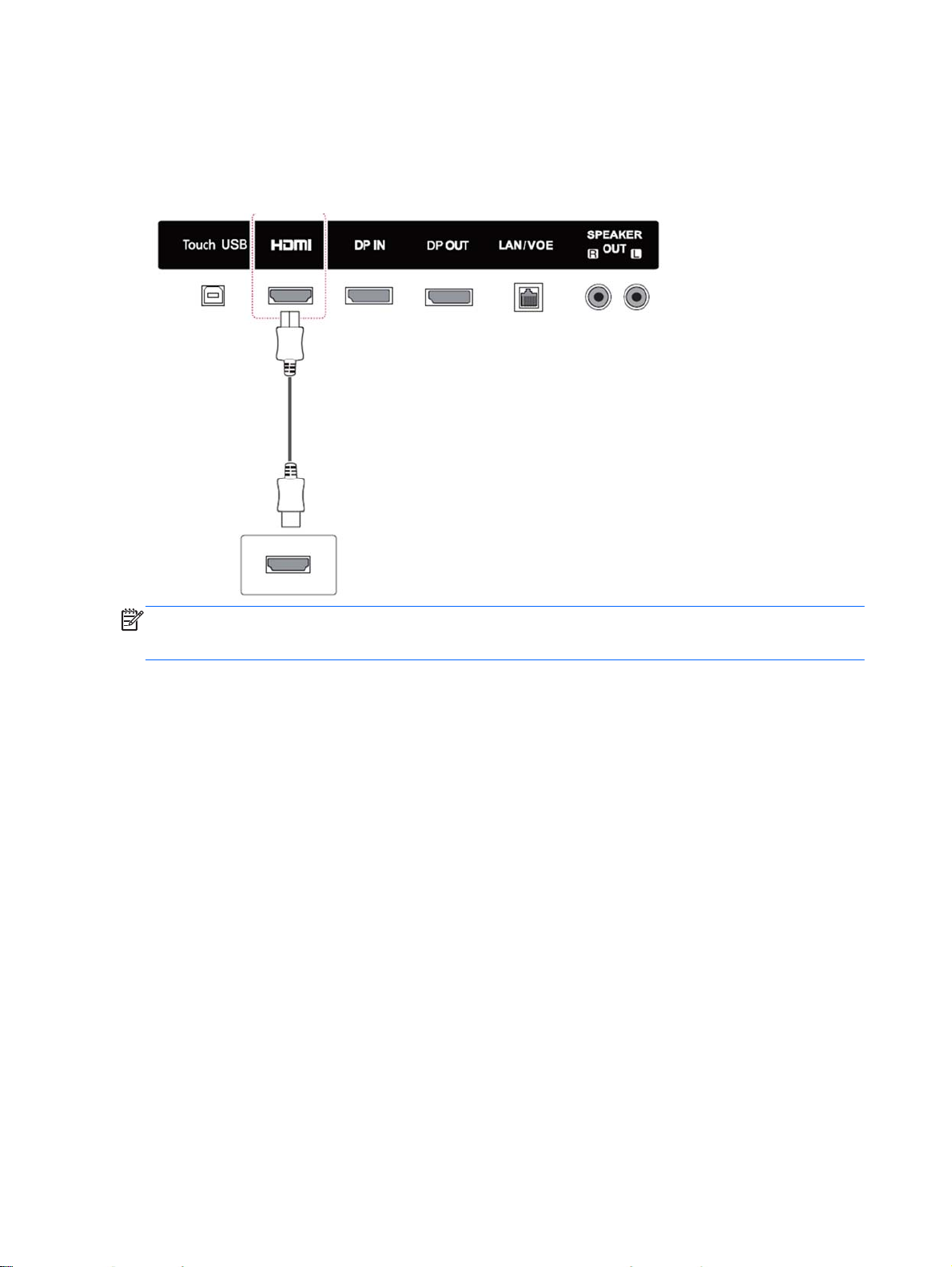
HDMI connection
Transmits the digital video and audio signals from an external device to the display. Connect the
external device and the display with the HDMI cable as shown on the following illustration.
Back of the product:
NOTE: Use a High Speed HDMI Cable.
High Speed HDMI Cables are tested to carry an HD signal up to 1080p and higher.
42 Chapter 7 Making connections
Page 53

Component connection
Transmits the analog video and audio signals from an external device to the display. Connect the
external device and the display with the 15 pin signal to RCA cable as shown on the following
illustration. To display images by using progressive scan, make sure to use the component cable.
The VGA/RCA cable and audio-in cable are not provided with the display.
Back of the product:
NOTE: When connecting to the Component port using the shared interface, the port must match up
to the input source. Otherwise, noise may occur.
Connecting to a Computer, HD receiver, DVD, or VCR 43
Page 54

Connecting to the LAN
a. Using a router (switch).
Connect one end of the LAN cable (1) to the display and the other end to the router (2). Connect
the second LAN cable to the router (3) and the other end of the LAN cable to a computer (4).
b. Using the Internet.
Connect one end of the LAN cable (1) to the display and the other end to the network (2).
Connect the second LAN cable to the network (3) and the other end of the LAN cable to a
computer (4).
Connecting to a USB
Connect a USB storage device such as s USB flash memory, external hard drive, MP3 player or a
USB memory card reader to the display and access the USB menu to use various multimedia files.
44 Chapter 7 Making connections
Page 55

Daisy chain displays
Use this function to digital video signal from a computer on multiple displays.
1. Connect a signal input cable (DisplayPort cable) to the DP IN port of the first display.
2. Connect one end of the signal input cable to the computer.
3. Connect one end of a signal input cable to the DP OUT port of the first display and the other end
to the DP IN of the second display.
DisplayPort cable
NOTE: The number of displays that can be connected to one output may vary depending on signal
status and cable loss. If the signal status is good, and there is no cable loss, it is possible to connect
up to 25 displays. If you want to connect more than this number of displays, it is recommended to use
a distributor.
When multi-connecting in/out cascade format, no loss cables are recommended.
DP OUT does not work when connecting to a third-party product.
Daisy chain displays 45
Page 56

8 Setting up the display for music, videos,
and photos
Connect the display to a local area network (LAN) via the LAN port as shown in the following
illustration and set up the network settings. The display only supports wired network connection. After
making a physical connection, a small number of networks may require the display network settings
to be adjusted. For most networks, the display will connect automatically without any adjustments.
For detail information, check your router manual.
CAUTION: Do not connect a modular phone cable to the LAN port.
Since there are various connection methods, please follow the specifications of your
telecommunication carrier.
To set up the network settings (if your display connected automatically, running setup again will not
disrupt the connection):
1. Press MENU to access the main menus.
2. Press the Navigation buttons to scroll to NETWORK and press OK.
3. Press the Navigation buttons to select Network Setting and press OK.
4. If you already set Network Setting, select Resetting. The new connection settings resets the
current network settings.
5. Select IP Auto Setting or IP Manual Setting.
46 Chapter 8 Setting up the display for music, videos, and photos
Page 57

If selecting IP Manual Setting, press the Navigation and Number buttons. IP addresses will
●
need to be input manually.
IP Auto Setting: Select this if there is a DHCP (Dynamic Host Configuration Protocol) server
●
(router) on the local area network (LAN) via wired connection, the display will automatically
be allocated an IP address. If you’re using a broadband router that has a DHCP server
function, the IP address will automatically be determined.
6. When you are finished, press EXIT.
CAUTION: The network setting menu will not be available until the display is connected to a
physical network.
Since there are various connection methods, HP recommends that you follow the specifications of
your telecommunication carrier.
NOTE: If you want to access the Internet directly on your display, the internet connection should
always be on.
If you cannot access the Internet, check the network conditions from a computer on your network.
When you use Network Setting, check the LAN cable or check if DHCP in the router is turned on.
If you do not complete the network settings, the network may not work properly.
Tips for network setting
Use a standard LAN cable with this display. Use a Cat5 or better with a RJ45 connector.
●
Many network connection problems during set up can often be fixed by resetting the router. After
●
connecting the display to the network, quickly power off and/or disconnect the power cable of the
network router. Then power on and/or connect the power cable again.
HP is not responsible for any malfunction of the display and/or the internet connection feature
●
due to communication errors/malfunctions associated with your internet connection, or other
connected equipment.
HP is not responsible for problems within your internet connection.
●
You may experience undesired results if the network connection speed does not meet the
●
requirements of the content being accessed.
Some internet connection operations may not be possible due to certain restrictions associated
●
with your Internet connection
Any internet fees, including connection charges, without limitation, are your responsibility.
●
A 10 Base-T or 100 Base-TX LAN port is required when using a wired connection to this display.
●
If your internet service does not allow for such a connection, you will not be able to connect the
display.
47
Page 58

Network status
1. Press MENU to access the main menus.
2. Press the Navigation buttons to scroll to NETWORK and press OK.
3. Press the Navigation buttons to select Network Status.
4. Press OK to check the network status.
5. When you are finished, press EXIT.
Option Description
Setting Return to the network setting menu.
Test Test the current network status after setting the network.
Close Return to the previous menu.
Connecting USB storage devices
You can use USB flash memory devices for content playback and multimedia features in the USB
built-in player.
Connect a USB flash memory or USB memory card reader to the display as shown on the following
illustration. The My media screen appears.
CAUTION: Do not turn the display off or remove a USB storage device while the EMF (My media)
menu is activated, as this could result in loss of files or damage to the USB storage device.
Back up your files saved on a USB storage device frequently, as you may lose or damage the files
and this may be not covered by the warranty.
Tips for using USB storage devices
Only a USB storage device is recognizable.
●
If the USB storage device is connected through a USB hub, the device is not recognizable.
●
A USB storage device using an automatic recognition program may not be recognized.
●
A USB storage device that uses its own driver will not be recognized.
●
48 Chapter 8 Setting up the display for music, videos, and photos
Page 59

The recognition speed of a USB storage device may depend on each device.
●
Do not turn off the display or unplug the USB device when the connected USB storage device is
●
working. When such a device is suddenly separated or unplugged, the stored files or the USB
storage device may be damaged.
Only use a USB storage device that has normal music files, image files or video files.
●
Use only a USB storage device that was formatted as a FAT32 file system, NTFS file system by
●
with the Windows operating system. In case of a storage device formatted with a different utility
program that is not supported by Windows, it may not be recognized.
Connect power to a USB storage device (over 0.5 A) that requires an external power supply. If
●
not, the device may not be recognized.
Connect a USB storage device with the cable included by the device maker.
●
Some USB storage devices may not be supported or operate smoothly.
●
File alignment method of USB storage devices can recognize up to 100 English characters.
●
Be sure to back up important files since data stored on a USB memory device may be damaged.
●
We will not be responsible for any data loss.
If the USB HDD does not have an external power source, the USB device may not be detected.
●
So be sure to connect the external power source. Please use a power adaptor for an external
power source.
If your USB memory device has multiple partitions, or if you use a USB multi-card reader, you
●
can use up to 4 partitions or USB memory devices.
If a USB memory device is connected to a USB multi-card reader, its volume data may not be
●
detected.
If the USB memory device does not work properly, disconnect and reconnect it.
●
How fast a USB memory device is detected differs from device to device.
●
If the USB is connected in Standby Mode, that drive will automatically be loaded when the
●
display is turned on.
The recommended capacity is 1 TB or less for a USB external hard disk and 32 GB or less for
●
USB memory.
Any device with more than the recommended capacity may not work properly.
●
If a USB external hard disk with a “Energy Saving” function does not work, turn the hard disk off
●
and on again to make it work properly.
USB storage devices below USB 2.0 are supported as well. But th
●
videos.
A maximum of 999 folders or files can be recognized under one folder.
●
It is recommended you use a certified USB storage device and cable. Otherwise, a USB storage
●
device may not be detected or a playback error may occur.
A USB 3.0 storage device may not work.
●
ey may not work properly with
Connecting USB storage devices 49
Page 60

Browsing files
Access the photo, music, or video lists and browse files.
1. Connect a USB storage device.
2. Press MENU to access the main menus.
3. Press the Navigation buttons to scroll to My Media and press OK.
4. Press the Navigation buttons to choose from Movie List, Photo List, or Music List and press OK.
Item Description
(1) Moves to upper level folder.
(2) Current page/Total pages.
(3) Corresponding buttons on the remote control.
(4) Current page/total pages of contents under the folder focused on (1).
(5) Contents under the folder focused on (1).
Button Description
Green button Press the green button to toggle between Photo List > Music List, Music List > Movie List or Movie
Yellow button A method to view as either large thumbnail folder or listing.
Blue button Convert to Mark Mode.
List > Photo List.
50 Chapter 8 Setting up the display for music, videos, and photos
Page 61

Supported file format
Type Supported file format
Movie DAT,MPG,MPEG,VOB,AVI,MP4,MKV,TS,T RP,TP,ASF,WMV,FLV)
Photo JPEG Baseline : 64 x 64 to 15360 x 8640
Movie (*.mpg/*.mpeg/*dat/*.ts/*.trp/*.tp/*.vob/*. mp4/*.mov/*.mkv/*.avi/*.asf/*.wmv/*.flv/*. avi(motionjpeg)/*. mp4(motion-jpeg)/*.mkv(motion-jpeg))supporting file
Video format : Xvid1.00, Xvid1.01, Xvid1.02, Xvid1.03, Xvid1.10 beta-1/beta-2, Mpeg-1, Mpeg-2,
Mpeg-4, H.264/AVC, VC1, JPEG, Sorenson H.263
Audio format : Dolby Digital, AAC, Mpeg, MP3, LPCM, HE-AAC, ADPCM, WMA
Bit rate : within 32 kbps to 320 kbps(MP3)
External Subtitle format : *.smi/*.srt/*.sub (MicroDVD,Subviewer1.0/2.0)/*.ass/*.ssa/*. txt(TMPlayer)/*
Internal Subtitle format : only, XSUB
Progressive : 64 x 64 to 1920 x 1440
You can play JPEG files only
●
Non-supported files are displayed in the form of predefined icon.
●
File extensions: .jpg, .jpeg, .jpe
Supported file format:
SOF0: baseline
●
SOF1: Extend Sequential
●
SOF2: Progressive
●
Photo size:
Min: 64 x 64
●
Max: Normal
●
Type: 15360 (W) x 8640 (H)
●
Progressive Type: 1920 (W) x 1440 (H)
●
Music MP3
Bit rate 32 to 320
Sampling rate MPEG1 Layer3 : 32 kHz, 44.1 kHz, 48 kHz
●
Sampling rate MPEG2 Layer3 : 16 kHz, 22.05 kHz, 24 kHz
●
Sampling rate MPEG2.5 Layer3 : 8 kHz, 11.025 kHz, 12 kHz
●
Content File Extensions : *.cts/ *.cse
Movie
File Extensions: *.mpg/*.mpeg/*.dat/*.ts/*. trp/*.tp/*.vob/*.mp4/*.mov/*.mkv/*.avi/*.asf/*. wmv/
*.avi(motion JPEG)/*.mp4(motion JPEG)/*. mkv(motion JPEG)
Video format: MPEG1, MPEG2, MPEG4,H.264/ AVC, Xvid 1.00,Xvid 1.01, Xvid 1.02, Xvid 1.03,Xvid
1.10-beta1/2, JPEG, VC1(WVC1/WMV3)
Audio format: MP2,MP3,Dolby Digital, LPCM, AAC, HE-AAC,LPCM, ADPCM, WMA, MP3
Photo: JPEG JPG PNG BMP
Supported file format:
Browsing files 51
Page 62

Playing videos
Your display shows all of the video files saved in a USB storage device or shared folder on a
computer.
1. Press the Navigation buttons to scroll to My Media and press OK.
SOF0: baseline
●
SOF1: Extend Sequential
●
SOF2: Progressive
●
Photo size:
Min: 64 x 64
●
Max: 136 x 768
●
Music: MP3
Bit rate: 32 kbps to 320 kbps
Sampling rate:
32 kHz, 44.1 kHz, 48 kHz (MPEG1 L3)
●
16 kHz, 22.05 kHz, 24 kHz (MPEG2 L3)
●
8kHz, 11.025 kHz, 12 kHz (MPEG2.5 L3)
●
2. Press the Navigation buttons to scroll to Movie List and press OK.
3. Press the Navigation buttons to scroll to a folder you want and press OK.
4. Press the Navigation buttons to scroll to a file you want and press OK.
Menu Description
Play marked Returns to the selected video file.
Mark All Mark all video files on the screen.
Unmark All Deselect all marked video files.
Exit Mark Mode Exit the Mark Mode.
5. Play a video.
NOTE: Non-supported files are displayed in the preview image by icon only .
Abnormal files are displayed in the form of a bitmap
.
6. Control playback by using the following buttons.
Button Description
Stops the playback.
Plays a video.
Pauses or resumes the playback.
Scans backward in a file.
52 Chapter 8 Setting up the display for music, videos, and photos
Page 63

Scans forward in a file.
MENU Show the Option menu.
Hide the menu on the full-sized screen.
Return to Movie List.
< or > Skips to specific points in a file during playback. The time of a specific point will appear on the status bar.
In some files, this function may not work properly.
Press the ENERGY SAVING button repeatedly to increase the brightness of your screen.
Tips for playing video files
Some user-created subtitles may not work properly.
●
Some special characters are not supported in subtitles.
●
HTML tags are not supported in subtitles
●
Subtitles in languages other than the supported languages are not available.
●
The screen may suffer temporary interruptions (image stoppage, faster playback, etc.) when the
●
audio language is changed.
A damaged video file may not be played correctly, or some player functions may not be usable.
●
Video files produced with some encoders may not be played correctly.
●
If the video and audio structure of recorded file is not interleaved, either video or audio is
●
outputted.
HD videos with a maximum of 1920x1080@25/30P or 1280x720@50/60P are supported,
●
depending on the frame.
Videos with resolutions higher than 1920X1080@25/30P or 1280x720@50/60P may not work
●
properly depending on the frame.
Video files other than the specified types and formats may not work properly.
●
Max bitrate of playable video file is 20 Mbps. (only, Motion JPEG : 10 Mbps).
●
We do not guarantee smooth playback of profiles encoded level 4.1 or higher in H.264/ AVC.
●
DTS Audio codec is not supported.
●
A video file more than 30 GB in file size is not supported for playback.
●
A video file name and its subtitle file name must be identical for it to be displayed.
●
Playing a video via a USB connection that does not support high speed may not work properly
●
Files encoded with GMC (Global Motion Compensation) may not be played.
●
When you are watching the video by Movie List function, you can adjust an image by Energy
●
Saving key on the remote control.
Video options
1. Press MENU to access the Pop-Up menus.
2. Press the Navigation buttons to scroll to Set Video Play, Set Video. or Set Audio and press OK.
Playing videos 53
Page 64

NOTE: Option values changed in Movie List do not affect Photo List and Music List.
Option value changed in Photo List and Music List are changed likewise in Photo List and Music List
excluding Movie List.
When replaying the video file after stopping, you can play from where it stopped previously.
When you select Set Video Play:
1. Press the Navigation buttons to scroll to show the Picture Size, Audio Language, Subtitle
Language or Repeat.
2. Press the Navigation buttons to scroll to make appropriate adjustments.
Menu Description
Picture Size Selects your desired picture format during video play.
Audio Language Changes the Language Group of the audio during video play. This option cannot be selected for files
Subtitle Language Turn on/off the subtitle.
Language Activated for SMI subtitle and can select the language within the subtitle.
Code Page Can select the font for subtitle. When set to default, same font as general menu will be used.
Sync Adjusts the time synchronization of the subtitle from -10 secs to +10 secs by steps of 0.5 secs during
Position Changes the position of the subtitle either up or down during video play.
Size Selects your desired Subtitle size during video play.
Repeat Turn on/off repeat function of video playback. When turned on, the file within the folder will be played
Code Page Description
Latin1 English, Spanish, French, German, Italian, Swedish, Finnish, Dutch, Portuguese, Danish, Romanian,
Latin2 Bosnian, Polish, Croatian, Czech, Slovak, Slovenian, Serbian, Hungarian
Latin4 Estonian, Latvian, Lithuanian
with a single audio track.
video play.
back repeatedly. Even when the repeated playback is turned off, it can run the playback if the file
name is similar to the previous file.
Norwegian, Albanian, Gaelic, Welsh, Irish, Catalan,Valencian
Cyrillic Bulgarian, Macedonian, Russian, Ukrainian, Kazakh
Greek Greek
Turkish Turkish
Korean Korean
54 Chapter 8 Setting up the display for music, videos, and photos
Page 65

NOTE: Only 10,000 sync blocks are supported within the subtitle file.
When playing a video, you can adjust the Picture Size by pressing the ARC button.
Subtitles in your language are only supported when the OSD menu is also in this language.
The code page options may be disabled depending on the language of the subtitle files.
Select the appropriate code page for the subtitle files.
When you select Set Video:
Press the Navigation buttons to scroll to make appropriate adjustments.
▲
When you select Set Audio:
1. Press the Navigation buttons to scroll to show the Sound Mode, Clear Voice II, or Balance.
2. Press the Navigation buttons to scroll to make appropriate adjustments.
Viewing photos
View image files saved in a USB storage device. The displays on the screen may differ from the
model.
1. Press the Navigation buttons to scroll to My Media and press OK.
2. Press the Navigation buttons to scroll to Photo List and press OK.
3. Press the Navigation buttons to scroll to a folder you want and press OK.
4. Press the Navigation buttons to scroll to a file you want and press OK.
Menu Description
View marked Display the selected photo file.
Mark All Mark all photo files on the screen.
Unmark All Deselect all marked photo files.
Exit Mark Mode Exit the Mark Mode.
5. View photos.
NOTE: Non-supported files are displayed the preview image by icon only.
Abnormal files are displayed in bitmap form.
Using photo options
Use the following options while viewing photos.
Option Description
Slideshow Starts or stops a slideshow with selected photos. If there are no selected photos, all photos saved in the
current folder display during a slideshow. To set a slideshow speed, select Option.
BGM Turns the background music (BGM) on or off. To set the background music folder, select Option. You
can adjust Option by MENU button on the remote control.
Rotates photos clockwise (90°, 180°, 270°, 360°).
Viewing photos 55
Page 66

NOTE: The supported photo size is limited. You cannot rotate a photo if the resolution of the rotated
width is larger than the supported resolution size.
View the photo by zoom in 2, 4 times.
NOTE: Photos with a resolution of 960x540 or less cannot be enlarged.
Press the ENERGY SAVING button repeatedly to change the brightness of your screen.
MENU
Slide Speed: Selects a slideshow speed (Fast, Medium, Slow).
●
TransitionEffect: Set the view mode of the slideshow.
●
BGM: Selects a music folder for the background music.
●
NOTE: You cannot change the music folder while the background music is playing.
You can only select the MP3 folder saved on the device that currently displays the photo.
Hides the option window. To display the options, press OK.
Return to Photo List.
Photo options
1. Press MENU to show the Option menus.
2. Press the Navigation buttons to scroll to Set Photo View, Set Video. or Set Audio and press OK.
NOTE: Option values changed in Movie List do not affect Photo List and Music List.
Option value changed in Photo List and Music List are changed likewise in Photo List and Music List
excluding Movie List.
When replaying the video file after stopping, you can play from where it stopped previously.
When you select Set Photo View:
1. Press the Navigation buttons to scroll to show the Slide Speed, Transition Effect, or BGM.
2. Press the Navigation buttons to scroll to make appropriate adjustments.
Transition Effect Option
Option Description
Sliding Pushes the current slide out of view as it plays to the next slide.
Stairs Pushes the current slide in a staircase shape as it plays to the next slide.
Door Open/Close Pushes the current slide like opening or closing the door as it plays to the next slide.
56 Chapter 8 Setting up the display for music, videos, and photos
Page 67

Shutter Pushes the current slide like drawing or pulling down the blind as it plays to the next slide
Fade In Fades the slide out slowly before playing to the next slide.
When you select Set Video:
Press the Navigation buttons to scroll to make appropriate adjustments.
▲
When you select Set Audio:
1. Press the Navigation buttons to scroll to show the Sound Mode, Clear Voice II, or Balance.
2. Press the Navigation buttons to scroll to make appropriate adjustments.
Listening to music
NOTE: Speakers must be installed on the display to listen to audio.
1. Press the Navigation buttons to scroll to My Media and press OK.
2. Press the Navigation buttons to scroll to Music List and press OK.
3. Press the Navigation buttons to scroll to a folder you want and press OK.
4. Press the Navigation buttons to scroll to a file you want and press OK.
Menu Description
Play marked Display the selected music file.
Mark All Mark all music files on the screen.
Unmark All Deselect all marked music files.
Exit Mark Mode Exit the Mark Mode.
5. Play music.
6. Control playback by using the following buttons.
Button Description
Stops playing back the file and moves back to the music list.
Plays a music file.
Pauses or resumes playback.
Skips to the previous file.
Skips to the next file.
Listening to music 57
Page 68

When playing, when you press the << button, the previous music file will be played. When you press the
>> button, the next music file will be played.
or
Green
button
MENU Show the Option menu.
< or > When using the < or > button during playback a cursor indicating forward or backward.
Start playing the selected music files and then move to the Music List.
Press the ENERGY SAVING button repeatedly to increase the brightness of your screen.
Hides the option window. To display the options, press OK.
When you press the EXIT button while the Music player is displayed, only the music will be stopped and
the player will not return to normal viewing. When you press the EXIT button while the music is stopped
or while the music player is hidden, the player will return to normal viewing.
Tips for playing music files
This display does not support the ID3 Tag embedded MP3 files.
●
NOTE: Non-supported files are displayed in the preview image by icon only .
Abnormal files are displayed as bitmaps
.
A damaged or corrupted music does not play but displays 00:00 in playtime.
A music downloaded from a paid service with copyright protection does not start but displays
inappropriate information in playtime.
If you press OK or (
The PLAY (
), Pause ( ), ,( ), ( ) buttons on the remote control are also available in this mode.
You can use the (
) buttons, audio and screen saver is stopped.
) button to select the next music and the ( ) button to select the previous music.
Music options
1. Press MENU to access the Pop-Up menus.
2. Press the Navigation buttons to scroll to Set Audio Play or Set Audio and press OK.
NOTE: Option values changed in Movie List do not affect Photo List and Music List.
Option value changed in Photo List and Music List are changed likewise in Photo List and Music List
excluding Movie List.
When you select Set Audio Play:
1. Press the Navigation buttons to scroll to show Repeat or Random.
2. Press the Navigation buttons to scroll to make appropriate adjustments.
When you select Set Audio:
1. Press the Navigation buttons to scroll to show the Sound Mode, Clear Voice II, or Balance.
2. Press the Navigation buttons to scroll to make appropriate adjustments.
58 Chapter 8 Setting up the display for music, videos, and photos
Page 69
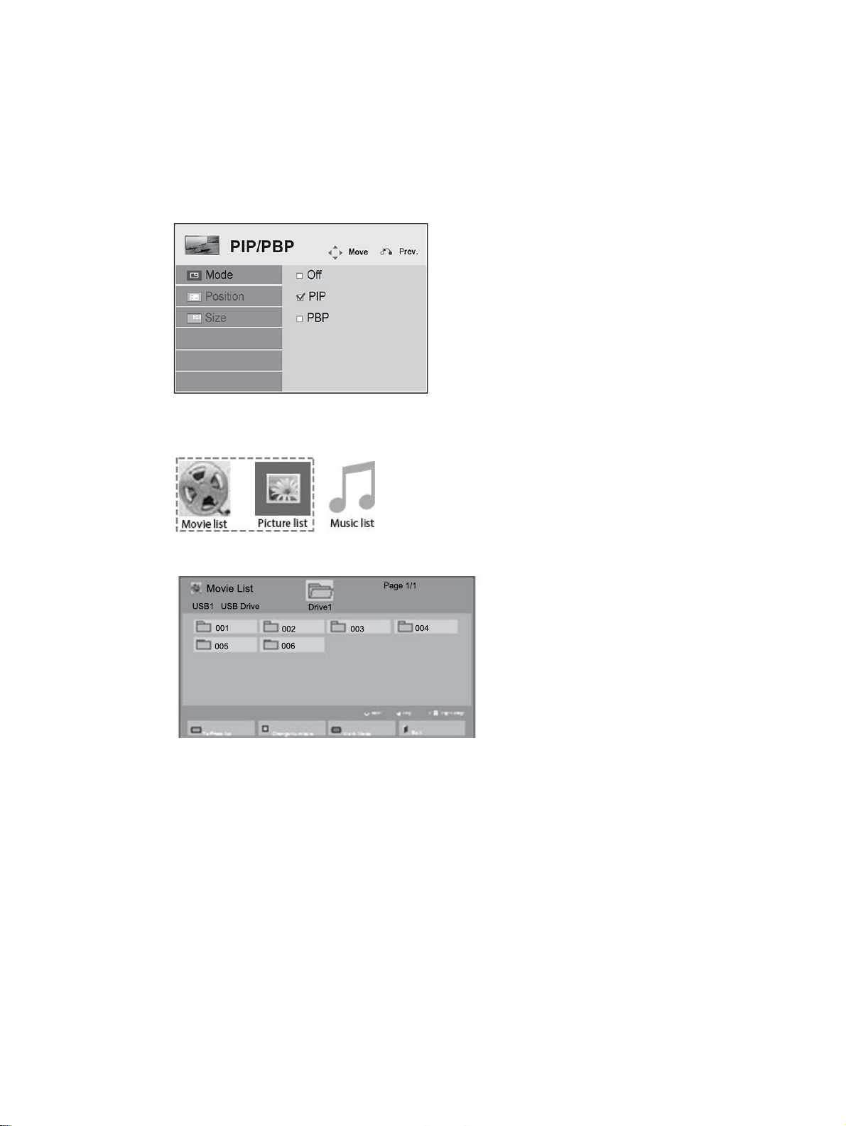
Using PIP/PBP
Displays videos or photos stored in a USB device on a single display by dividing it into the main and
sub screens.
1. Press the MENU button to move to OPTION and press OK.
2. Press PIP/PBP to select PIP or PBP and then press OK.
3. Select Movie List or Photo List from My Media. (With PIP/PBP selected, the Music List is
deactivated.)
4. Select a file you want and then press OK.
Using PIP/PBP 59
Page 70

5. Select the PIP or PBP icon from the play list.
6. Select either Main or Sub for sound. You must select the output sound before running the PIP or
PBP function.
7. The sub screen is displayed on the main screen.
60 Chapter 8 Setting up the display for music, videos, and photos
Page 71

9 Operating the touch screen
Installing the touch software
Microsoft Windows 8/ Windows 7(plug and play)
NOTE: For instructions about connecting the USB cable, see Touch USB cable connection
on page 16. When you connect the USB cable between the monitor and a computer running
Windows 8 or Windows 7, the touch driver software will automatically install. The driver software may
take a minute to install, and for Windows 8 and Windows 7 a message will display on the monitor
screen indicating that the driver software has been installed successfully. After the touch driver
software is installed, you can select, launch, and drag objects using the touch screen. To make a
selection, touch the screen.
NOTE: Touch function is supported on the primary display only. The secondary displays will not
support touch function when using multiple displays.
NOTE: Multi-touch gestures are supported in Windows 8, Windows 7 Home Premium, Professional,
Enterprise, and Ultimate operating system editions only. Multi-touch is not supported in Windows 7
Home Basic or Starter editions.
To verify that the touch driver is installed:
Windows 8—From the Start screen, point to the far-right upper or lower corner of the screen to
●
display the charms, select Settings, select Control Panel, select System and Security, select
System, and make sure that Pen and Touch: Limited Touch Support with 10 Points is listed.
If the driver is installed correctly, four HID-compliant device entries, one USB input device, and
one Microsoft input configuration device is displayed under Human Interface Devices.
Also, under Mice and other pointing devices, one HID-compliant mouse entry is displayed.
Windows 7—Select Start, select Control Panel, select System and Security, select System, and
●
ensure that Pen and Touch: Touch Input Available with 10 Touch Points is listed in the System
section.
Using the touch screen
To use the touch screen on Windows 8
Plug a USB cable into the touch USB port on the back of the display.
Installing the touch software 61
Page 72
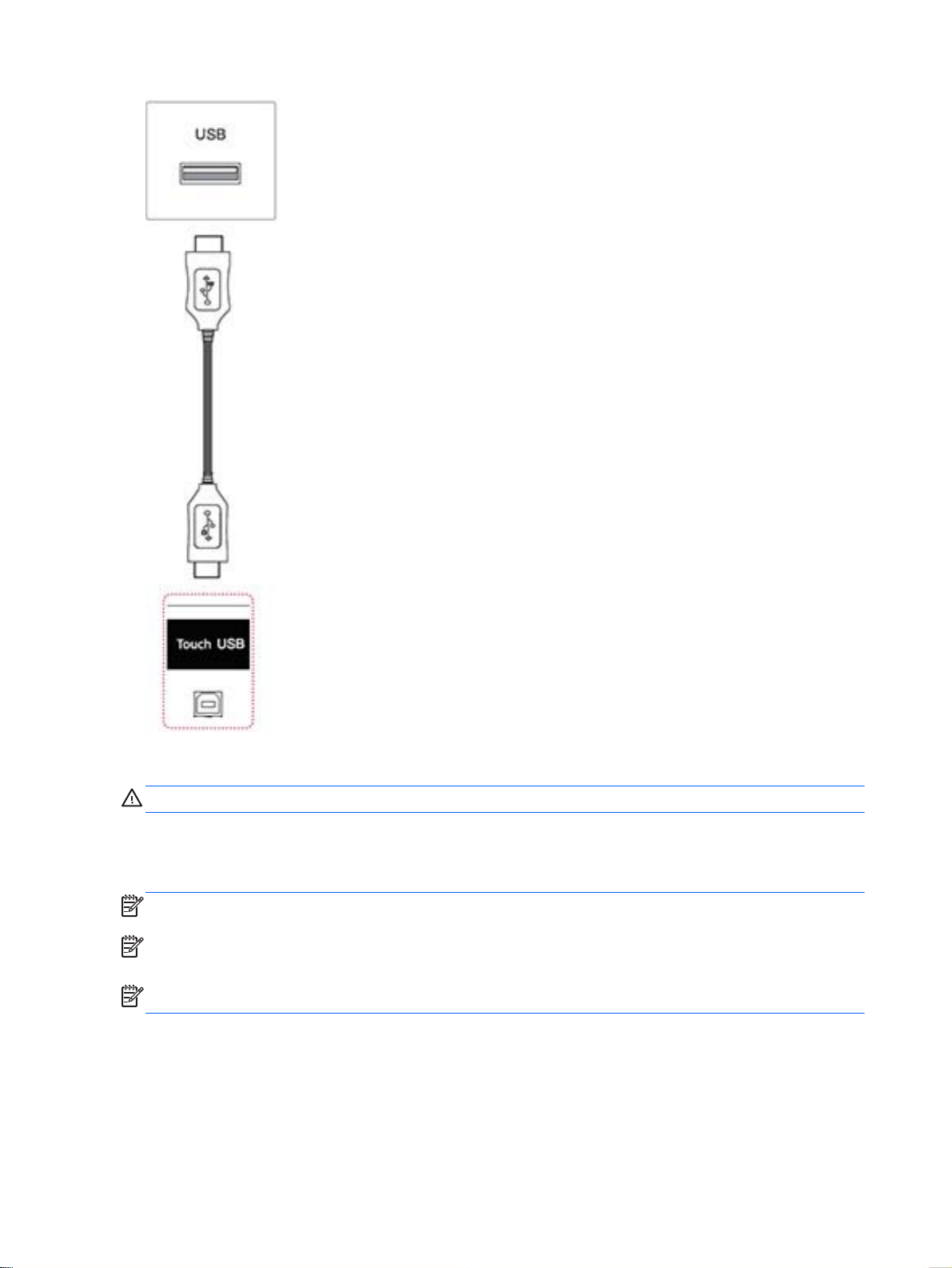
Then, connect the USB cable to your computer so that it automatically recognizes the touch screen
display.
CAUTION: You can use the touch screen after the computer recognizes the display.
From the Start screen, point to the far-right upper or lower corner of the screen to display the charms,
select Settings, select Control Panel, select System and Security, and then select System. The
number of touch-points supported is displayed under Pen and Touch.
NOTE: The display can respond to five touch points when connected to a Windows 8 computer.
NOTE: When using the touch screen display, HP recommends that you set the screen aspect ratio
to 16:9 or Just Scan.
NOTE: For more information about gestures and settings on Windows 8, see Windows Help.
To use the touch screen on Windows 7
Plug a USB cable into the touch USB port on the back of the display.
62 Chapter 9 Operating the touch screen
Page 73
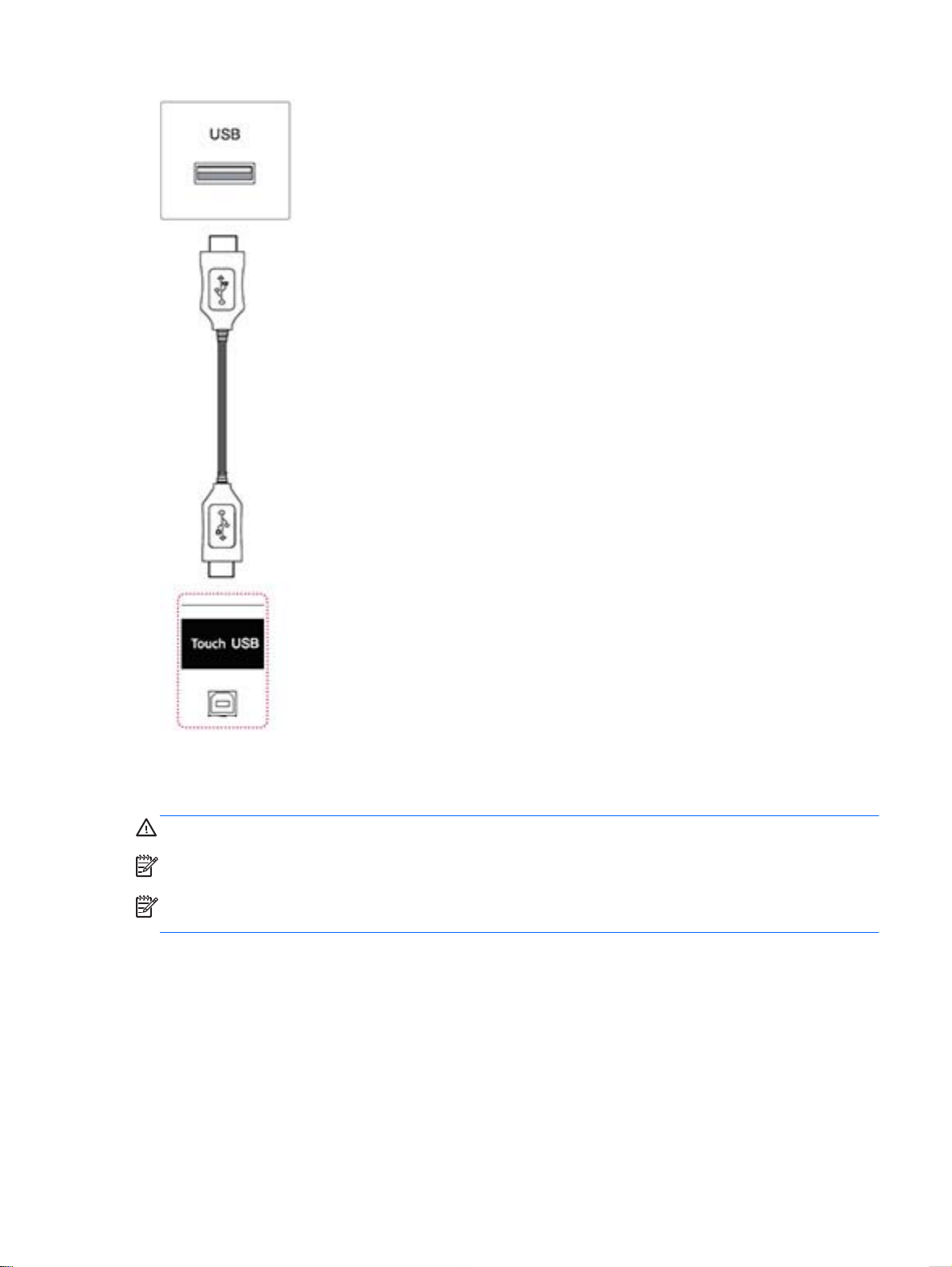
Connect the USB cable to your computer so that it automatically recognizes the touch screen display.
Go to Control Panel, select System and Security, and then select System. The number of touchpoints supported is displayed under Pen and Touch.
CAUTION: You can use the touch screen after the computer recognizes the display.
NOTE: The display can respond to five touch points when connected to a Windows 7 computer.
NOTE: When using the touch screen display, HP recommends that you set the screen aspect ratio
to 16:9 or Just Scan.
For more information about gestures and settings on Windows 7, refer to Windows Help.
Using the touch screen 63
Page 74

10 Troubleshooting
Touch screen troubleshooting
Cause Solution
Computer does not recover from Sleep mode when the touch
screen is touched.
The USB cable is quickly removed from the display and
reinserted, and the touch function is lost.
Multi-touch gestures do not function on Windows 7 Home
Basic or Starter editions, or Windows Vista.
The Start, Close, and other icons are too small to touch with
a finger.
Touch operation does not function properly on lower
resolution video modes that are not displayed in full screen.
A single touch is recognized as two touches. If using a paint
tool, a single finger creates two lines.
When the display used is in a multi-screen configuration, the
touch function on the secondary displays do not work.
Touch point accuracy is poor. Touch accuracy is optimized by using full screen mode. The
Sleep mode recovery is not supported by the touch screen.
Use the keyboard or mouse to recover from Sleep mode.
Windows takes a minimum amount of time to adjust system
parameters when a USB device is either removed or
connected. Try removing the USB cable again, wait for at
least five seconds, and then plug it in again.
Only Windows 7 Home Premium, Professional, Enterprise,
and Ultimate editions support multi-touch gestures
Windows 8 and Windows 7 provides a large icon feature that
supports touch screen functions. This feature can be
accessed in the Control Panel.
Although the display supports a fill-to-aspect ratio function,
the touch controller does not know how to respond to lessthan-full screen images. Either change the resolution to 1920
x 1080, or access the OSD menu and select 16:9 aspect
ratio or Just Scan.
The touch controller has a limitation on the size of the “touch”
area. A fingertip touch usually works better than a flat
forefinger or thumb touch.
The USB connection is only capable of operating a single
touch screen display.
display should be adjusted to 16:9 aspect ratio or Just Scan.
Adjust the aspect ratio to Just Scan if in DTV input
(DisplayPort or HDMI).
Touch operation does not function. Check the USB cable between the display (Touch USB)
5 point touch-points are not detected in Windows 7 or 8. Restart your computer or try removing the USB cable, wait
No image is displayed.
Cause Solution
Is the product power cord connected? See if the power cord is properly connected to the outlet.
Does the 'Out of range' message appear? The signal from the computer (video card) is out of the
64 Chapter 10 Troubleshooting
connector and the computer running Windows 8 or Windows
7. The display must be set as primary display in Windows.
for at least 5 seconds, and then plug it in again.
vertical or horizontal frequency range of the product. Adjust
the frequency range using the following specifications:
Maximum resolution RGB : 1920 x 1080 @ 60 Hz
Page 75

No image is displayed.
Cause Solution
HDMI/DisplayPort : 1920 x 1080 @ 60 Hz
Does the 'Check signal cable' message appear? The signal cable between computer and product is not
connected. Check the signal cable.
Press the INPUT menu in the remote control to check the
input signal.
'Unknown Product' message appears when the product is connected.
Cause Solution
Did you install the driver? See if the plug & play function is supported by referring to the
video card user manual.
The screen image looks abnormal.
Cause Solution
Is the screen position wrong? D-Sub analog signal - Press the AUTO button on the remote
Do thin lines appear on the background screen? D-Sub analog signal - Press the AUTO button in the remote
Horizontal noise appears or the characters look blurred. D-Sub analog signal - Press the AUTO button in the remote
The screen is displayed abnormally. The proper input signal is not connected to the signal port.
After-image appears on the product.
Cause Solution
control to automatically select the optimal screen status for
the current mode. If adjustment is not satisfactory, use the
Position OSD menu.
See if the video card resolution and frequency are supported
by the product. If the frequency is out of range, set to the
recommended resolution in the Control Panel Display Setting
menu.
control to automatically select an optimal screen status that
fits into the current mode. If adjustment is not satisfactory,
use the Clock OSD menu.
control to automatically select an optimal screen status that
fits into the current mode. If adjustment is not satisfactory,
use the Phase OSD menu.
Connect the signal cable that matches with the source input
signal.
After-image appears when the product is turned off. If you use a fixed image for a long time, the pixels may
become damaged. Use the screen-saver function.
When a dark image is displayed on the screen after an
image with high contrast (black and white or gray), this may
cause image sticking. This is normal for LCD screen.
65
Page 76

The audio function does not work.
Cause Solution
No sound? See if the audio cable is connected properly.
Adjust the volume.
See if the sound is set properly.
Sound is too dull. Select the appropriate equalize sound.
Sound is too low. Adjust the volume.
Screen color is abnormal.
Cause Solution
Screen has poor color resolution (16 colors). Set the number of colors to more than 24 bits (true color)
Select Control Panel - Display - Settings - Color Table menu
in Windows.
Screen color is unstable or mono-colored. Check the connection status of the signal cable. Or, reinsert
the computer video card.
Do black spots appear on the screen? Several pixels (red, green, white or black color) may appear
on the screen, which can be attributable to the unique
characteristics of the LCD panel. It is not a malfunction of the
LCD.
The operation does not work normally.
Cause Solution
The power suddenly turned off. Is the sleep timer set?
Check the power control settings. Power interrupted.
66 Chapter 10 Troubleshooting
Page 77

A Specifications
41.92-inch (106.5-cm) model
LCD Panel Screen type 1064.67 mm Wide (41.92 inch) TFT (Thin Film Transistor) LCD
Pixel pitch 0.4833 mm (H) x 0.4833 mm (V)
Video Signal Max resolution 1920 x 1080 @ 60 Hz
Recommended resolution 1920 x 1080 @ 60 Hz
Horizontal frequency 30 kHz to 83 kHz
Vertical frequency 50 Hz to 60 Hz
Synchronization type Separate Sync, Composite Sync, Digital
(Liquid Crystal Display) Panel.
Visible diagonal size : 1064.67 mm
It may not be supported depending on the OS or video card
type.
It may not be supported depending on the OS or video card
type.
Input connector 15-pin D-Sub type, HDMI (digital), RS-232C, LAN, DisplayPort,
USB, Touch USB, Audio, Speaker, IR
Power Rated voltage AC 100-240 V~ 50/60 Hz 1.3 A
Power consumption On Mode : 95 W Typ
Sleep Mode (if WOL is off) : ≤ 0.5 W
Sleep Mode (if WOL is on) : ≤ 2.0 W
Off Mode : ≤ 0.5 W
Environmental
conditions
Dimensions W x H x D, weight
Touch Touch Type IR Spread Touch
Operating Temperature
Operating Humidity
Storage Temperature
Storage Humidity
(no stand or speakers)
0°C to 40°C
10% to 80%
-20°C to 60°C
5% to 95%
990.9 mm x 585.0 mm x 92.7 mm
(39.0 in x 23.0 in x 3.6 in)
20.7 kg
(45.6 lbs)
Multitouch 5 Point + Gestures (Windows 8 and Windows 7)
Software Support Windows 8 and Windows 7
41.92-inch (106.5-cm) model 67
Page 78

Embedded Software Support WES7P
Minimum Finger Spacing 15 mm (center to center)
For models that support speakers:
Audio RMS Audio Output 10 W + 10 W (R + L)
Dimensions
NOTE: Product specifications may change without prior notice due to upgrade of product functions.
Input Sensitivity 0.7 Vrms
Speaker Impedance 8 Ω
4-M6 wall mounting screws
Depth 10.0 mm (Max)
68 Appendix A Specifications
Page 79

46.96-inch (119.3-cm) model
LCD Panel Screen type 1192.78 mm Wide (46.96 inch) TFT (Thin Film Transistor) LCD
Pixel pitch 0.5415 mm (H) x 0.5415 mm (V)
Video Signal Max resolution 1920 x 1080 @ 60 Hz
Recommended resolution 1920 x 1080 @ 60 Hz
Horizontal frequency 30 kHz to 83 kHz
Vertical frequency 50 Hz to 60 Hz
Synchronization type Separate Sync, Composite Sync, Digital
Input connector 15-pin D-Sub type, HDMI (digital), RS-232C, LAN, DisplayPort,
Power Rated voltage AC 100-240 V~ 50/60 Hz 1.4 A
Power consumption On Mode : 100 W Typ
(Liquid Crystal Display) Panel.
Visible diagonal size : 1192.78 mm
It may not be supported depending on the OS or video card type.
It may not be supported depending on the OS or video card type.
USB, Touch USB, Audio, Speaker, IR
Sleep Mode (if WOL is off) : ≤ 0.5 W
Sleep Mode (if WOL is on) : ≤ 2.0 W
Off Mode : ≤ 0.5 W
Environmental
conditions
Dimensions W x H x D, weight
Touch Touch Type IR Spread Touch
Multitouch 5 Point + Gestures (Windows 8 and Windows 7)
Software Support Windows 8 and Windows 7
Embedded Software Support WES7P
Minimum Finger Spacing 15 mm (center to center)
Operating Temperature
Operating Humidity
Storage Temperature
Storage Humidity
(not including stand or
speakers)
0°C to 40°C
10% to 80%
-20°C to 60°C
5% to 95%
1102.7 mm x 647.8 mm x 95.3mm
(43.4 in x 25.5 in x 3.8 in)
24.8 kg
(54.7 lbs)
For models that support speakers:
46.96-inch (119.3-cm) model 69
Page 80

Audio RMS Audio Output 10 W + 10 W (R + L)
Dimensions
NOTE: Product specifications may change without prior notice due to upgrade of product functions.
Dimensions
Input Sensitivity 0.7 Vrms
Speaker Impedance 8 Ω
4-M6 wall mounting screws
Depth 20.0 mm (Max)
70 Appendix A Specifications
Page 81

Recognizing preset display resolutions
The display resolutions listed below are the most commonly used modes and are set as factory
defaults. This display automatically recognizes these preset modes and they will appear properly
sized and centered on the screen.
Preset Pixel format Horizontal Frequency (Hz) Vertical Frequency (Hz)
1 640 x 480 31.469 59.940
*2 720 x 400 31.469 70.087
3 800 x 600 37.879 60.317
4 1024 x 768 48.363 60.004
5 1280 x 720 45.000 60.000
6 1280 x 800 49.702 59.810
7 1280 x 1024 63.981 60.020
8 1440 x 900 55.469 59.901
9 1600 x 900 60.000 60.000
10 1680 x 1050 65.290 59.954
11 1920 x 1080 67.5 60.00
*RGB mode only
Recognizing preset display resolutions 71
Page 82

DTV mode
Resolution Component HDMI/DisplayPort (DTV)
480i o x
576i o x
480p o o
576p o o
720p o o
1080i o o
1080p o o
NOTE: HDMI/DisplayPort input mode may identified in PC resolution: 640 x 480 / 60 Hz, 1280 x
720 / 60 Hz, 1920 x 1080 / 60 Hz or DTV resolutions: 480p, 720p, 1080p.
NOTE: Vertical frequency: To enable the user to watch the product display, screen image should be
changed tens of times every second like a fluorescent lamp. The vertical frequency or refresh rate is
the times of image display per second. The unit is Hz.
Horizontal frequency: The horizontal interval is the time to display one vertical line. When 1 is divided
by the horizontal interval, the number of horizontal lines displayed every second can be tabulated as
the horizontal frequency. The unit is kHz.
IR codes
All models do not support the HDMI/USB function.
Some key codes are not supported depending on the model.
Code (Hexa) Function Note
95 Energy Saving R/C BUTTON
08
0B INPUT R/C BUTTON
C4 Display On R/C BUTTON
C5 Display Off R/C BUTTON
43 MENU R/C BUTTON
40 UP (∧) R/C BUTTON
41 Down (∨) R/C BUTTON
07 Left (<) R/C BUTTON
06 Right (>) R/C BUTTON
44 OK R/C BUTTON
28 BACK
POWER R/C BUTTON (ON/OFF)
R/C BUTTON
5B EXIT R/C BUTTON
72 Appendix A Specifications
Page 83

4D PSM R/C BUTTON
02 Volume (+) R/C BUTTON
03 Volume (-) R/C BUTTON
09 MUTE R/C BUTTON
E0 Bright ^ (Page Up) R/C BUTTON
E1 Bright v (Page Down) R/C BUTTON
10 to 19 Number key 0 to 9 R/C BUTTON
72 Red key (ID ON) R/C BUTTON
71 Green key (ID OFF) R/C BUTTON
63 Yellow key R/C BUTTON
61 Blue key R/C BUTTON
7B TILE R/C BUTTON
76 ARC (4:3) R/C BUTTON
77 ARC (16:9) R/C BUTTON
AF ARC (ZOOM) R/C BUTTON
79 ARC (MARK) R/C BUTTON
99 Auto config R/C BUTTON
B1
B0
BA
8F R/C BUTTON
8E
R/C BUTTON
R/C BUTTON
R/C BUTTON
R/C BUTTON
IR codes 73
Page 84

B Agency regulatory notices
Federal Communications Commission notice
This equipment has been tested and found to comply with the limits for a Class B digital device,
pursuant to Part 15 of the FCC Rules. These limits are designed to provide reasonable protection
against harmful interference in a residential installation. This equipment generates, uses, and can
radiate radio frequency energy and, if not installed and used in accordance with the instructions, may
cause harmful interference to radio communications. However, there is no guarantee that interference
will not occur in a particular installation. If this equipment does cause harmful interference to radio or
television reception, which can be determined by turning the equipment off and on, the user is
encouraged to try to correct the interference by one or more of the following measures:
Reorient or relocate the receiving antenna.
●
Increase the separation between the equipment and the receiver.
●
Connect the equipment into an outlet on a circuit different from that to which the receiver is
●
connected.
Consult the dealer or an experienced radio or television technician for help.
●
Modifications
The FCC requires the user to be notified that any changes or modifications made to this device that
are not expressly approved by Hewlett Packard Company may void the user's authority to operate the
equipment.
Cables
Connections to this device must be made with shielded cables with metallic RFI/EMI connector hoods
to maintain compliance with FCC Rules and Regulations.
Declaration of Conformity for products marked with the FCC logo (United States only)
This device complies with Part 15 of the FCC Rules. Operation is subject to the following two
conditions:
1. This device may not cause harmful interference.
2. This device must accept any interference received, including interference that may cause
undesired operation.
For questions regarding the product, contact:
Hewlett Packard Company
P. O. Box 692000, Mail Stop 530113
Houston, Texas 77269-2000
Or, call 1-800-HP-INVENT (1-800 474-6836)
74 Appendix B Agency regulatory notices
Page 85

For questions regarding this FCC declaration, contact:
Hewlett Packard Company
P. O. Box 692000, Mail Stop 510101
Houston, Texas 77269-2000
Or, call (281) 514-3333
To identify this product, refer to the Part, Series, or Model number found on the product.
Canadian notice
This Class B digital apparatus meets all requirements of the Canadian Interference-Causing
Equipment Regulations.
Avis Canadien
Cet appareil numérique de la classe B respecte toutes les exigences du Règlement sur le matériel
brouilleur du Canada.
European Union regulatory notice
Products bearing the CE marking comply with the following EU Directives:
Low Voltage Directive 2006/95/EC
●
EMC Directive 2004/108/EC
●
Ecodesign Directive 2009/125/EC, where applicable
●
CE compliance of this product is valid if powered with the correct CE-marked AC adapter provided by
HP.
Compliance with these directives implies conformity to applicable harmonized European standards
(European Norms) that are listed in the EU Declaration of Conformity issued by HP for this product or
product family and available (in English only) either within the product documentation or at the
following web site:
The compliance is indicated by one of the following conformity markings placed on the product:
www.hp.eu/certificates (type the product number in the search field).
For non-telecommunications products and for EU
harmonized telecommunications products, such as
Bluetooth® within power class below 10mW.
For EU non-harmonized telecommunications products (If
applicable, a 4-digit notified body number is inserted
between CE and !).
Please refer to the regulatory label provided on the product.
The point of contact for regulatory matters is: Hewlett-Packard GmbH, Dept./MS: HQ-TRE,
Herrenberger Strasse 140, 71034 Boeblingen, GERMANY.
Canadian notice 75
Page 86

German ergonomics notice
HP products which bear the “GS” approval mark, when forming part of a system comprising HP brand
computers, keyboards and monitors that bear the “GS” approval mark, meet the applicable ergonomic
requirements. The installation guides included with the products provide configuration information.
Japanese notice
Korean notice
Power cord set requirements
The display power supply is provided with Automatic Line Switching (ALS). This feature allows the
display to operate on input voltages between 100–120V or 200–240V.
The power cord set (flexible cord or wall plug) received with the display meets the requirements for
use in the country where you purchased the equipment.
If you need to obtain a power cord for a different country, you should purchase a power cord that is
approved for use in that country.
The power cord must be rated for the product and for the voltage and current marked on the product's
electrical ratings label. The voltage and current rating of the cord should be greater than the voltage
and current rating marked on the product. In addition, the cross-sectional area of the wire must be a
minimum of 0.75 mm² or 18 AWG, and the length of the cord must be between 6 feet (1.8 m) and 12
feet (3.6 m). If you have questions about the type of power cord to use, contact an authorized HP
service provider.
A power cord should be routed so that it is not likely to be walked on or pinched by items placed upon
it or against it. Particular attention should be paid to the plug, electrical outlet, and the point where the
cord exits from the product.
Japanese power cord requirements
For use in Japan, use only the power cord received with this product.
CAUTION: Do not use the power cord received with this product on any other products.
76 Appendix B Agency regulatory notices
Page 87

Product environmental notices
California Perchlorate Material Notice
Perchlorate material - special handling may apply. See http://www.dtsc.ca.gov/hazardouswaste/
perchlorate/. This product’s real-time clock battery or coin cell battery may contain perchlorate and
may require special handling when recycled or disposed of in California.
Materials disposal
This HP product contains mercury in the fluorescent lamp in the display LCD that might require
special handling at end-of-life.
Disposal of this material can be regulated because of environmental considerations. For disposal or
recycling information, contact the local authorities or the Electronic Industries Alliance (EIA)
www.eiae.org.
Disposal of waste equipment by users in private households in the European Union
This symbol on the product or on its packaging indicates that this product must not be disposed of
with your household waste. Instead, it is your responsibility to dispose of your waste equipment by
handing it over to a designated collection point for the recycling or waste electrical and electronic
equipment. The separate collection and recycling of your waste equipment at the time of disposal will
help to conserve natural resources and ensure that it is recycled in a manner that protects human
health and the environment. For more information about where you can drop off your waste
equipment for recycling, please contact the local city office, the household waste disposal service or
the shop where you purchased the product.
Chemical substances
HP is committed to providing our customers with information about the chemical substances in our
products as needed to comply with legal requirements such as REACH (Regulation EC No
1907/2006 of the European Parliament and Council). A chemical information report for this product
can be found at
www.hp.com/go/reach.
HP recycling program
HP encourages customers to recycle used electronic hardware, HP original print cartridges, and
rechargeable batteries. For more information about recycling programs, go to
Restriction of Hazardous Substances (RoHS)
A Japanese regulatory requirement, defined by specification JIS C 0950, 2005, mandates that
manufacturers provide Material Content Declarations for certain categories of electronic products
offered for sale after July 1, 2006. To view the JIS C 0950 material declaration for this product, visit
www.hp.com/go/jisc0950.
www.hp.com/recycle.
Product environmental notices 77
Page 88

11363-2006
11363-2006
India restriction of hazardous substances (RoHS)
This product complies with the “India E-waste (Management and Handling) Rule 2011” and prohibits
use of lead, mercury, hexavalent chromium, polybrominated biphenyls or polybrominated diphenyl
ethers in concentrations exceeding 0.1 weight % and 0.01 weight % for cadmium, except for the
exemptions set in Schedule 2 of the Rule.
78 Appendix B Agency regulatory notices
Page 89

Turkey EEE regulation
In Conformity with the EEE Regulation
EEE Yönetmeliğine Uygundur
Ukraine Restriction of Hazardous Substances
Обладнання відповідає вимогам Технічного регламенту щодо обмеження використання деяких
небезпечних речовин в електричному та електронному обладнані, затвердженого постановою
Кабінету Міністрів України від 3 грудня 2008 № 1057.
The equipment complies with requirements of the Technical Regulation, approved by the Resolution
of Cabinet of Ministry of Ukraine as of December 3, 2008, in terms of restrictions for the use of certain
dangerous substances in electrical and electronic equipment.
Taiwan Battery Disposal Warning
Product environmental notices 79
Page 90

C Controlling multiple products
Use this method to connect several products to a single computer. You can control several products
at a time by connecting them to a single computer.
In the Option menu, Set ID must be between 1 and 255 without being duplicated.
Connecting the cable
Connect the RS-232C cable as shown.
The RS-232C protocol is used for communication between the computer and product. You can turn
the product on/off, select an input source or adjust the OSD menu from your computer.
RS-232C configurations
80 Appendix C Controlling multiple products
Page 91

Communication parameter
Baud Rate: 9600 baud Rate (UART)
Data Length: 8 bit
Parity Bit: None
Stop Bit: 1 bit
Flow Control: None
Communication Code: ASCII code
Use a crossed (reverse) cable
Command reference list
Command Data (Hexadecimal)
01. Power k a 00 to 01
02. Input Select k b Refer to ‘Input Select’
03. Aspect Ratio k c Refer to ‘Aspect Ratio’
04. Energy Saving f l Refer to ‘Energy Saving’
12
05. Picture Mode d x Refer to ‘Picture Mode’
06. Contrast k g 00 to 64
07. Brightness k h 00 to 64
08. Sharpness k k 01 to 0a
09. Color Temperature k u 00 to 03
10. Auto configuration j u 01
11. Balance k t 00 to 64
12. Sound Mode d y Refer to ‘Sound Mode’
13. Treble k r 00 to 64
14. Bass k s 00 to 64
15. Speaker d v 00 to 01
16. Volume Mute k e 00 to 01
17. Volume Control k f 00 to 64
18. Time f a Refer to ‘Time’
19. Off Timer (On/Off Timer) Time f e Refer to ‘Off Timer’
20. On Timer (On/Off Timer) Time f d Refer to ‘On Timer’
21. Sleep Time f f 00 to 08
22. Power On Delay f h 00 to 64
Communication parameter 81
Page 92

23. Language f I Refer to ‘Language’
24. ISM Method j p Refer ti ‘ISM Method’
25. Reset f k 00 to 03
26. Tile Mode d d 00 to FF
27. Tile ID Set d l Refer to ‘Tile ID’
28. Tile H Position d e 00 to 32
29. Tile V Position d f 00 to 32
30. Tile H Size d g 00 to 32
31. Tile V Size d h 00 to 32
32 Natural Mode (In Tile Mode) d j 00 to 01
33. DPM Select f j 00 to 01
34. Temperature Value d n FF
35. Remote Lock/Key Lock k m 00 to 01
36. Key m c Refer to ‘Key’
37. OSD Select k l 00 to 01
38. Operating Time Return d l FF
39. Serial No f y FF
40. S/W Version f z ffH
41. Backlight m g 00 TO 64
42. Display Name v a ffH
43. Abnormal State k z ffH
44. Display Location v b ffH
45. Player Name v d ffH
46. DCHP (VOE) v e ffH
47. Scheduling Input Select f u f1H to f7H
48. IP Address (VOE) v f ffH
49. Auto Detection f g 00H to 01H
50. Subnet Mask (VOE) v g ffH
51. IP Address (NSM) v k ffH
52. Mac Address (VOE) v h ffH
53. Check VOE Availability v I ffH
54. Mac Address (NSM) v j ffH
55. Product Name f v ffH
82 Appendix C Controlling multiple products
Page 93

NOTE: During USB operations such as EMF, all commands except Power(k a) and Key(m c) are
not executed and treated as NG.
Transmission / Receiving protocol
Transmission
[Command1][Command2][ ][Set ID][ ][Data][Cr]
* [Command1]: First command to control the set.
* [Command2]: Second command to control the set.
* [Set ID]: Set ID with which you want to communicate. Enter [Set ID] = ‘00(0x00’ to communicate
with all sets regardless of their Set ID numbers.
* [Data]: Information passed to the set.
* [Data1]: Information passed to the set.
* [Data2]: Information passed to the set.
* [Data3]: Information passed to the set.
* [Cr]: Carriage Return. ASCII code ‘0x0D’.
* [ ]: ASCII code space ‘0x20’
Acknowledgement
[Command2][ ][Set ID][ ][OK/NG][Data][x]
* When the product receives data normally, it sends an acknowledgement (ACK) in the format above.
If data is in read mode, it indicates the data that shows the current status. If data is in read mode, it
simply indicates the data that is sent from the computer.
* If a command is sent with Set ID '00' (=0x00), the data is reflected to all display and they do send an
acknowledgement (ACK).
* If the data value 'FF' is sent in control mode via RS-232C, the current setting value of a function can
be checked (only for some functions).
* Some commands are not supported depending on the model.
01. Power (Command: k a)
To control the Power On/Off the display.
Transmission
[k][a][ ][Set ID][ ][Data][Cr]
Data
00 : Power off
01 : Power on
Acknowledgement
[a][ ][Set ID][ ][OK/NG][Data][x]
Transmission / Receiving protocol 83
Page 94

* Only when the display is fully powered on, the Acknowledgement signal is returned properly. *
There may be a certain time of delay between the Transmission and Acknowledgement signals.
02. Input Select (Command: k b)
To select the Input Source for display.
Transmission
[k][b][ ][Set ID][ ][Data][Cr]
Data
07: RGB (PC)
08: HDMI (DTV)
09: HDMI (PC)
Oa: DisplayPort (DTV)
Ob: DisplayPort (PC)
0c: VOE (PC)
0d: VOE (DTV)
Acknowledgement
[b][ ][Set ID][ ][OK/NG][Data][k]
*Some input signals may not be supported depending on the model.
03. Aspect Ratio (Command: k c)
To adjust the screen format.
Transmission
[k][c][ ][Set ID][ ][Data][Cr]
Data
01: 4:3
02: 16:9
04: Zoom
09: Just scan (720p or more)
(Component, HDMI/ Display Port DTV)
* RGB, HDMI/Display Port PC mode
(1:1)
10 to 1F: Cinema Zoom 1 to 16
(AV, Component, HDMI DTV)
* Available data types differ depending on the input signal. For more information, see the aspect ratio
section of this guide.
* The aspect ratio may differ depending on the model's input configuration.
Acknowledgement
84 Appendix C Controlling multiple products
Page 95

[c][ ][Set ID][ ][OK/NG][Data][x]
04. Energy Saving (Command: f l)
To set the Energy Saving function.
Transmission
[f][l][ ][Set ID][ ][Data][Cr]
Data
00: Off
01: Minimum - Level 2
02: Medium – Level 2
03. Maximum – Level 3
05. Screen Off
Acknowledgement
[l][ ][Set ID][ ][OK/NG][Data][x]
** It may not be supported depending on the model.
05. Picture Mode (Command: d x)
To select the Picture Mode.
Transmission
[d][x][ ][Set ID][ ][Data][Cr]
Data
00: Vivid
01: Standard
02: Cinema
03. Sport
04: Game
Acknowledgement
[x][ ][Set ID][ ][OK/NG][Data][x]
06. Contrast (Command: k g)
To adjust the screen contrast.
Transmission
[k][g][ ][Set ID][ ][Data][Cr]
00 to 64: Contrast 0 to 100
Acknowledgement
[g][ ][Set ID][ ][OK/NG][Data][x]
Transmission / Receiving protocol 85
Page 96

07. Brightness (Command: k h)
To adjust the screen brightness.
Transmission
[k][h][ ][Set ID][ ][Data][Cr]
Data
00 to 64: Brightness 0 to 100
Acknowledgement
[h][ ][Set ID][ ][OK/NG][Data][x]
08. Sharpness (Command: k k)
To adjust the screen sharpness.
* This function is available only in AV/Component input.
Transmission
[k][k][ ][Set ID][ ][Data][Cr]
Data
00 to 64: Sharpness 0 to 100
Acknowledgement
[k][ ][Set ID][ ][OK/NG][Data][x]
09. Color Temperature (Command: k u)
To adjust the screen color temperature.
* This function is available only in AV/Component input.
Transmission
Data
[k][u][ ][Set ID][ ][Data][Cr]
00 to 64: Warm 50 to Cool 50
Acknowledgement
[u][ ][Set ID][ ][OK/NG][Data][x]
10. Auto Configuration (Command: j u)
To adjust the picture position and minimize image shaking automatically.
(Only available for RGB-PC input.)
Transmission
[j][u][ ][Set ID][ ][Data][Cr]
Data
01: Set
86 Appendix C Controlling multiple products
Page 97

Acknowledgement
[u][ ][Set ID][ ][OK/NG][Data][x]
11. Balance (Command: k t)
To adjust the sound balance.
Transmission
[k][t][ ][Set ID][ ][Data][Cr]
Data
00 to 64: Left 50 to Right 50
Acknowledgement
[t][ ][Set ID][ ][OK/NG][Data][x]
12. Sound Mode (Command: d y)
To adjust the sound mode.
Transmission
[d][y][ ][Set ID][ ][Data][Cr]
Data
01: Standard
02: Music
03: Cinema
04: Sport
05: Game
Acknowledgement
[y][ ][Set ID][ ][OK/NG][Data][x]
13. Treble (Command: k r)
To adjust the Treble values.
Transmission
[k][r][ ][Set ID][ ][Data][Cr]
Data
00 to 64: Treble 0 to 100
Acknowledgement
[r][ ][Set ID][ ][OK/NG][Data][x]
14. Bass (Command: ks)
To adjust the Bass values.
Transmission
Transmission / Receiving protocol 87
Page 98

[k][s][ ][Set ID][ ][Data][Cr]
Data
00 - 64: Bass 0 to 100
Acknowledgement
[s][ ][Set ID][ ][OK/NG][Data][x]
15. Speaker (Command: d v)
To select the speaker on/off.
Transmission
[d][v][ ][Set ID][ ][Data][Cr]
Data
00: Off
01 : On
Acknowledgement
[v][ ][Set ID][ ][OK/NG][Data][x]
16. Volume Mute (Command: k e)
To adjust the sound balance.
Transmission
[k][e][ ][Set ID][ ][Data][Cr]
Data
00: Mute (Volume Off)
01: Current volume (Volume On)
Acknowledgement
[e][ ][Set ID][ ][OK/NG][Data][x]
17. Volume Control (Command: k f)
To set the playback volume.
Transmission
[k][f][ ][Set ID][ ][Data][Cr]
Data
00 to 64: Volume 0 to 100
Acknowledgement
[f][ ][Set ID][ ][OK/NG][Data][x]
18. Time (Command: f a)
To set the Time 1 (Year/ Month/ Day) values.
88 Appendix C Controlling multiple products
Page 99

Transmission
[f][a][ ][Set ID][ ][Year][ ][Month][ ][Day of Month][] [Hour][][Minute][][Daylight Savings Time][Cr]
Data
Year
00 to 63: 2000 to 2099
Month
01 to 0C: January to December
Day of Month
01 to 1E: 1 to 31
Hour
00 to 17: 00 to 23 hours
Minutes
00 to 3B: 00 to 59 minutes
Daylight Saving Time
00: Off (only)
Acknowledgement
[a][][Set ID][][OK/NG][Year][Month][Day of Month][Hour][Minute][Daylight Saving Time][x]
19. Off Timer(On/Off Timer Time (Command: f e)
To set the Off Timer(Repeat Mode/ Time) function.
Transmission
[f][e][ ][Set ID][ ][Data1][ ][Data2][ ][Data3][Cr]
Data1
1. f1h to f7h (Read data)
F1: Read the 1st Off Time data
F2: Read the 2nd Off Time data
F3: Read the 3rd Off Time data
F4: Read the 4th Off Time data
F5: Read the 5th Off Time data
F6: Read the 6th Off Time data
F7: Read the 7th Off Time data
2. e1h-e7h (Delete one index), e0h (Delete all indexes)
E0: Delete all Off Time data
E1: Delete the 1st Off Time data
E2: Delete the 2nd Off Time data
Transmission / Receiving protocol 89
Page 100

E3: Delete the 3rd Off Time data
E4: Delete the 4th Off Time data
E5: Delete the 5th Off Time data
E6: Delete the 6th Off Time data
E7: Delete the 7th Off Time data
3. 01h to 06h (Set the day of week for Off Time)
00: Off
01: Once
02. Daily
03: Monday to Friday
04: Monday to Saturday
05: Saturday to Sunday
06. Sunday
07. Monday
08. Tuesday
09. Wednesday
0A. Thursday
0B. Friday
0C. Saturday
Data2
00 to 17: 00 to 23 Hours
Data3
00 to 3B: 00 to 59 Minutes
* To read or delete the Off Time list, set FFH for [Data2] and [Data3].
(Example 1: fe 01 f1 ff ff - Read the 1st Off Time data.)
(Example 2: fe 01 e1 ff ff - Delete the 1st Off Time data.)
(Example 3: fe 01 04 02 03 - Set the Off Time to "Monday to Saturday, 02:03".)
* This function is supported only when 1 (Year/Month/ Day) and 2 (Hour/Minute/Second) are set.
Acknowledgement
[e][ ][Set ID][ ][OK/NG][Data1][Data2][Data3][x]
20. On Timer(On/Off Timer) Time (Command: f d)
To set the On Timer(On/Off Timer) function.
Transmission
[f][d][ ][Set ID][ ][Data1][ ][Data2][ ][Data3][Cr]
90 Appendix C Controlling multiple products
 Loading...