

Page 1

LCS60 Network Interface
for Ethernet R3.0
Installation and Administration
Guide
255-111-107
Issue 3
July 1996
Page 2

Copyright 1996 Lucent Technologies
All Rights Reserved
Printed in USA
Federal Communications Commission Statement
This equipment generates, uses, and can radiate radio frequency energy and if not installed and used
in accordance with the instruction manual, may cause interference to radio communications. It has
been tested and found to comply with the limits for a Class A computing device pursuant to Subject J
or Part 15 of FCC rules.
Trademarks
CommKit®, Datakit®, and StarKeeper® are registered trademarks of Lucent Technologies.
AppleTalk®, AppleShare®, EtherTalk®, Mac®, and Macintosh® are registered trademarks of Apple
Computer Company.
ChameleonNFS® is a registered trademark of IBM Corp.
DECnet is a trademark of Digital Equipment Company.
HP® is a registered trademark of Hewlett-Packard Co.
Hydralube Blue® is a registered trademark of Arnco Equipment Co.
InterPPP is a trademark of InterCon Systems Corp.
IPX® is a registered trademark of Novell, Inc.
NetWare® is a registered trademark of Novell, Inc.
PC/TCP® is a registered trademark of FTP Software, Inc.
Polywater® is a registered trademark of Polywater Company.
Sun and SunOS are trademarks of Sun Microsystems, Inc.
UNIX® is a registered trademark of Novell, Inc., in the United
States and other countries, licensed exclusively through X/Open Company, Ltd.
Windows® is a registered trademark of Microsoft Corporation.
WINS is a trademark of Wollongong Group, Inc.
XNS® is a registered trademark of Xerox Corp.
Ordering Information
Additional copies of this document can be ordered by calling:
U.S.A.: 1-800-432-6600 Canada: 1-800-255-1242 Other Areas: 1-317-352-8557
or, by writing to: Lucent Technologies Customer Information Center
Attn: Customer Service Representative
P.O. Box 19901
Indianapolis, IN 46219
Issue 2 1-1
Page 3

Table of Contents
1
1
Trademarks
Feature Description
Document Organization 1-1
Reference Documentation 1-2
Apple References 1-3
Gateway References 1-3
PPP References 1-4
SLIP Reference 1-4
Other References 1-4
Overview 1-4
Benefits 1-5
LAN Protocols 1-6
TCP/IP 1-6
Domain Name Server (DNS) Resolver 1-6
Simple Network Management Protocol (SNMP) 1-6
Routing Information Protocol (RIP) 1-7
AppleTalk Protocol 1-7
AppleTalk Network Number and Zone Assignment 1-8
IPX Protocol 1-9
IPX Virtual Network Assignment 1-9
Remote Access Protocols 1-10
TCP/Async Gateway Service 1-10
TCP Service Ports 1-11
Serial Line IP (SLIP) 1-11
Point-to-Point Protocol (PPP) 1-12
Van Jacobson TCP/IP Header Compression 1-12
Compressed IPX Header (CIPX) 1-13
AppleTalk Remote Access Protocol (ARAP) 1-13
Multiple IP Subnetworks 1-13
IP Routing 1-13
Security Groups 1-15
Issue 2 i
Page 4

Table of Contents
IP Address Assignment by the LCS60 1-17
Hardware Features 1-17
Enhanced Processor 1-17
Fiber Interface 1-18
Network Security 1-18
Copy Protection 1-19
Administration 1-19
Backup/Restore 1-19
R3.0 Upgrade 1-20
Remote Upgrade 1-20
Centralized Network Management 1-20
Manual Pages 1-21
Customer Assistance 1-22
2
Hardware Installation
Introduction 2-1
Controls and Indicators 2-1
Site Preparation 2-2
Space Requirements 2-4
Cabling 2-4
EMI Considerations 2-5
Required Equipment 2-5
Assembly 2-6
Unpacking 2-6
Installing the LCS60 2-6
Rack Mounting 2-6
Wall Mounting 2-8
Table-Top Mounting 2-8
Connecting the System Console 2-9
Serial Port Optioning (DTE/DCE) 2-9
Direct Connection to the LCS60 2-12
Connection through a Data Switch 2-12
Connection through Modems 2-17
Connection through StarKeeper II NMS 2-17
Connecting the Fiber Interface 2-19
Routing the Optical Fiber Cable 2-19
Installing the CPM-HS Module and Optical Fiber
Cable 2-20
Configuration of the Lucent Technologies Data Switch
– LCS60 2-21
ii Issue 2
Page 5

Table of Contents
Dialogues 2-22
Enter Group Name 2-22
Define the Local Address for the LCS60 2-22
Configure the CPM-HS Module 2-24
Power and Grounding 2-25
Power-Up Procedures 2-25
Power-Down Procedures 2-27
Verify LCS60 Console Connection 2-27
Verify Fiber Connection 2-28
Configure the LCS60 2-29
LAN Connections 2-29
Ethernet 2-29
3
4
General LCS60 Software Configuration
Introduction 3-1
Preliminary Hardware Requirements 3-1
Preliminary Configuration Requirements 3-2
Specific Services 3-3
Initial Setup 3-3
Configure Protocols and Gateway Services —
srvsetup 3-10
Configure Default Route, DNS, and SNMP 3-23
Default Route – dftroute* 3-24
Domain Name Server – dns 3-25
SNMP Manager – snmp 3-26
Starting the LCS60 3-27
Base Level Backup 3-27
Configuration Changes 3-28
Administrative and Maintenance Commands 3-29
PPP – Configuration and
Administration
LCS60 Configuration and Connection for PPP Service 4-1
PPP Service Connection Dialstrings 4-13
Privately Administered Static IP Address 4-15
Reserved IP Address 4-16
Issue 2 iii
Page 6

Table of Contents
Dynamically Assigned IP Address 4-17
Administration 4-18
Show Session Examples 4-18
Call Trace Example 4-20
Log File 4-21
Related Commands 4-21
5
6
SLIP – Configuration and
Administration
LCS60 Configuration and Connection for SLIP Service 5-1
SLIP Service Connection Dialstrings 5-9
Privately Administered IP Address 5-10
Reserved IP Address 5-11
Dynamically Assigned IP Address 5-12
Administration 5-13
Stop Example 5-13
Call Trace Example 5-14
Errors 5-14
Log File 5-14
Related Commands 5-15
ARAP – Configuration and
Administration
LCS60 Configuration and Connection for ARAP
Service 6-1
ARAP Service Connection Dialstring 6-5
Administration 6-5
Show Service Example 6-5
Show Session Example 6-6
Call Trace Example 6-6
Log File 6-7
Related Commands 6-7
iv Issue 2
Page 7

Table of Contents
7
8
Gateway Services – Configuration and
Administration
LCS60 Configuration and Connection for Gateway
Service 7-1
Access to Gateway Services – Dialstrings 7-8
Telnet Service 7-8
Inactivity Timeout Option 7-9
Return to DESTINATION Option 7-10
User Information 7-10
Async-to-TCP Gateway Service 7-11
TCP-to-Async Gateway Service 7-12
UUCP Feature 7-13
Data Switch to LCS60 to LAN 7-13
LAN to LCS60 to Data Switch 7-15
Example UUCP Service Using SunOS 4.0 7-16
Example UUCP Service Using NCR 4.0 7-17
Administration 7-18
Service Ports 7-18
Trace TCP/Async 7-19
Error Messages 7-19
Log Files 7-20
Administration
Basics 8-1
Logging On 8-1
System Console 8-2
Remote Administration 8-2
lcsadm Interface 8-3
Common Commands 8-4
Initial System Setup (initsetup) 8-5
Top Directory Commands 8-5
Session Directory Commands 8-7
Ports Directory Commands 8-10
Service Directory Commands 8-12
Manager Directory Commands 8-13
Config Directory Commands 8-16
Issue 2 v
Page 8

Table of Contents
Typical Administrative Tasks 8-21
Show Session Example 8-22
Log Level Example 8-23
Change the Default Route Example 8-23
Summary Output Examples 8-24
System Console Parameters– Autobaud 8-24
Backup and Restore Operations 8-25
Generic vs. Variable Files 8-26
Local and Remote Modes 8-27
Backup/Restore (Tape) – Local Mode 8-27
To Back Up to Tape 8-27
To Restore from Tape 8-29
To List the Contents of a Tape 8-30
Centralized Backup/Restore – Remote Mode 8-30
Security — Authorizing Clients and Servers 8-31
Access to Backup/Restore Functions – Clients and
Servers 8-32
Defining Backup/Restore Servers on a Client 8-33
Defining Backup/Restore Clients on the Server 8-34
Backup or Restore Functions 8-35
Creating a Tape 8-38
Network Access Password Option 8-38
Deleting the Network Access Password 8-40
Changing the Network Access Password 8-40
Status 8-40
Error Messages 8-41
Error Messages from the LCS60 Fiber Interface 8-42
Console Error Messages 8-42
Hardware Error Messages 8-42
Server Error Messages 8-44
Call Error Messages 8-44
Lucent Technologies Data Switch Server Log File 8-45
Additional Log Files 8-46
9
vi Issue 2
Maintenance
Reload System Software 9-1
UNIX System Software Installation 9-1
UFS Utility Fixes Tape Installation 9-7
inet Package Removal 9-8
Page 9

Table of Contents
LCS60 Application Software Installation 9-9
Removing the LCS60 Application Software 9-13
Upgrade 9-15
Remote Upgrade 9-16
Installing an Upgrade on a Remote Upgrade Client 9-16
Processor Board Firmware Update 9-19
Processor Diagnostics - MVME197 9-23
VMEDKHS Diagnostics 9-25
Connection Verification 9-28
LCS60 to Data Switch Connected Host Verification
(dkcu) 9-28
LCS60 to Data Switch Verification – Loopback Test
(dkcu) 9-29
LCS60 to Local Ethernet Host Verification (ping) 9-29
Memory Dump 9-30
After the Dump is Completed 9-32
A
B
Issue 2 vii
Originating Group Security
srvtab A-1
Server Table A-1
System Field A-2
Service Field A-3
Flags Field A-4
User Field A-5
Program Field A-6
Initial Parms Field A-7
Server Table Scanning Rules A-8
Modifications to the Server Table A-9
Server Table Validation and Matching A-9
StarKeeper II NMS
Configuration of the StarKeeper II NMS B-1
Diskette or Tape Installation B-1
StarKeeper II NMS – Configuration Commands B-4
Alarms to StarKeeper II NMS B-6
Page 10

Table of Contents
C
D
E
User Error Messages
Cable Error Message C-1
Outgoing Call Error Messages C-1
Incoming Error Messages C-9
SLIP Sessions C-10
Software Installation – Fujitsu or
Seagate ST5660N Drive
Reload System Software D-1
UNIX System Software Installation D-1
Manual Pages
ATLOG E-1
ATNETSTAT E-2
ATPING E-4
DKCU E-6
DKMAINT E-8
FTP E-9
IFCONFIG E-19
IFSTAT E-21
IFTRACE E-24
IPXNETSTAT E-26
IPXPING E-27
NETSTAT E-28
NSLOOKUP E-30
PING E-34
PULL E-35
PUSH E-37
ROUTE E-40
STATLCS E-42
TELNET E-43
viii Issue 2
Page 11

Table of Contents
F
G
User Information
Introduction F-1
Client Software Configuration F-1
Client Packages F-2
Mac Connection – CCL Script F-2
CCL and Modem Hints F-5
CCL F-5
Modem F-6
PPP Service Examples F-6
Windows 95 – IPX over PPP F-6
PC Configuration F-7
PPP Connection F-9
WIN PC/TCP 3.0 F-9
PC Configuration F-9
PPP Connection F-11
InterPPP F-14
Connection F-14
SLIP Service Examples F-19
ChameleonNFS 4.0 F-19
ARAP Service Example F-22
Connection (via Modem) F-22
Glossary
Glossary G-1
General G-1
Parameters G-3
AppleTalk Network/Zone (atalkas) G-3
Ethernet Interface (etherif) G-4
DNS Resolver (dns) G-5
Define Service Sessions (maxsessions) G-5
SLIP/PPP Service (ipas/ipx) G-5
TCP-to-Asynchronous Gateway Services (srvports) G-6
Subnetwork Configuration (subnet) G-7
Report Fields G-8
Session Directory G-8
Ports Directory G-16
Service Directory G-17
Issue 2 ix
Page 12

Table of Contents
Manager Directory G-19
Server Directory G-19
I
Index
Index I-1
x Issue 2
Page 13

Figures
Figure 1-1: LCS60 as an AppleTalk Router 1-8
Figure 1-2: AppleTalk Virtual Zone 1-8
Figure 1-3: IPX Virtual Network 1-9
Figure 1-4: IP Routing with the LCS60 1-14
Figure 1-5: IP Address Assignment 1-16
Figure 2-1: Mounting the LCS60 Cabinet 2-7
Figure 2-2: MVME712M Header Locations and Factory Jumper Placements 2-10
Figure 2-3: System Console Connections– Direct 2-12
Figure 2-4: System Console Connections– through a Data Switch 2-16
Figure 2-5: System Console Connections– through Modems 2-17
Figure 2-6: System Console Connections– through StarKeeper II NMS 2-18
Figure 2-7: LCS60 Rear Panel AC Connections 2-26
Figure 3-1: Example Network 3-1
Figure 3-2: initsetup 3-4
Figure 3-3: srvsetup 3-10
Figure 4-1: Example Network– PPP Service 4-1
Figure 4-2: Configuring PPP Service for IP, IPX, and AppleTalk 4-2
Figure 5-1: Example Network– SLIP Service 5-1
Figure 5-2: Configuring SLIP Service 5-2
Figure 6-1: Example Network– ARAP Service 6-1
Figure 6-2: Configuring ARAP Service 6-2
Figure 7-1: Example Network– Gateway Services 7-1
Figure 7-2: Gateway Services Configuration 7-2
Figure 8-1: lcsadm Interface Directory Structure 8-4
Figure 9-1: Faceplates 9-23
Figure 9-2: Verifying Connections, Example Network 9-28
Figure F-1: Windows 95 IPX Over PPP– Example Screens F-8
Figure F-2: Windows 95 IPX Over PPP– Connect To Example Screen F-8
Figure F-3: PC/TCP Example Screens F-12
Figure F-4: PC/TCP Session Configuration Screen Example F-13
Figure F-5: Network Control Panel F-16
Figure F-6: Modem Port and PPP Screens F-16
Figure F-7: IP Address Screen F-17
Issue 2 xi
Page 14

Table of Contents
Figure F-8: PPP Connection Screen F-18
Figure F-9: AppleTalk Status Window F-18
Figure F-10: Custom Interface Window F-19
Figure F-11: Custom Setup Window F-20
Figure F-12: Login Settings Window F-20
Figure F-13: ARAP Remote Connection– Example F-23
Figure F-14: ARAP Remote Access Setup– Connection Screen F-23
Figure F-15: ARAP Remote Access Setup– Modem Example F-24
Figure F-16: ARAP Remote Access Status Screen– Example F-25
xii Issue 2
Page 15

Tables
Table 1-1: Online Manual Pages 1-21
Table 2-1: Controls and Indicators 2-2
Table 2-2: Specifications 2-3
Table 2-3: Required Additional Equipment 2-5
Table 2-4: System Console (and Port) Configuration 2-9
Table 2-5: MVME712M Module Optioning 2-10
Table 2-6: RS-232 Interface 2-11
Table 3-1: Protocol and Services Commands 3-9
Table 3-2: Configuration Commands– Config Directory 3-28
Table 3-3: Administrative/Maintenance Commands– Config Directory 3-29
Table 7-1: Gateway Services– Log Files 7-20
Table 8-1: Start/stop Command Dependencies 8-7
Table 8-2: Backup/Restore Functions 8-35
Table 8-3: Log Files 8-47
Table A-1: Server Table Flags A-4
Table A-2: User ID Mapping Options A-6
Table A-3: Program Arguments Specification A-7
Issue 2 xiii
Page 16

Table of Contents
xiv Issue 2
Page 17

Screens
Screen 2-1: TY Configuration Dialogue 2-13
Screen 2-2: MSM Configuration Dialogue 2-14
Screen 3-1: LCS60 Top Directory 3-5
Screen 4-1: Configure IP Network Security Group– Example 4-3
Screen 4-2: Configure Reserved IP Address– Example 4-5
Screen 4-3: Configure IPX Parameters– Example 4-7
Screen 4-4: Configure AppleTalk Virtual Network– Example 4-10
Screen 4-5: Configure the Ethernet Interface– Example 4-12
Screen 5-1: Configure IP Network Security Group– Example 5-3
Screen 5-2: Configure Reserved IP Address– Example 5-5
Screen 5-3: Configure the Ethernet Interface– Example 5-7
Screen 6-1: Configure AppleTalk Virtual Network– Example 6-3
Screen 7-1: Gateway Service Configuration– Example 7-4
Screen 8-1: Top Directory 8-5
Screen 8-2: Session Directory 8-8
Screen 8-3: Ports Directory 8-10
Screen 8-4: Service Directory 8-12
Screen 8-5: Manager Directory 8-14
Screen 8-6: Server Directory 8-15
Screen 8-7: Config Directory 8-17
Screen 8-8: LCS60 Backup and Restore Configuration Menu 8-26
Screen 8-9: Backup/Restore Menu 8-28
Screen 8-10: Tape Backup Management Menu 8-28
Screen 8-11: Centralized Backup/Restore Menu– Server 8-32
Screen 8-12: Centralized Backup Server Definition Menu 8-33
Screen 8-13: Centralized Backup Client Definition Menu 8-34
Screen 8-14: Centralized Backup Operations Menu 8-35
Screen 8-15: Centralized Backup Operations Menu– Server 8-36
Screen 8-16: Tape Backup Management Menu– Server 8-38
Screen 8-17: TCP-to-Async Gateway with Network Access Password 8-39
Screen 9-1: How to Enter System Responses 9-2
Screen 9-2: UFS Utility Fixes Maintenance Tape Installation 9-7
Screen 9-3: inet Package Removal 9-8
Issue 2 xv
Page 18

Table of Contents
Screen 9-4: LCS60 Application Software Installation 9-9
Screen 9-5: LCS60 Application Software Removal– R2.0 Example 9-14
Screen 9-6: set and env Commands 9-22
Screen 9-7: Example diag cpm for CPM-HS Module 9-26
Screen 9-8: Service Menu 9-31
Screen D-1: How to Enter System Responses D-2
Screen F-1: CCL Script– Example F-3
Screen F-2: Sample LCS60 dialup.scr F-10
Screen F-3: slip.ini File Fragment F-21
xvi Issue 2
Page 19

1
Feature Description
Document Organization 1-1
Reference Documentation 1-2
Apple References 1-3
Gateway References 1-3
PPP References 1-4
SLIP Reference 1-4
Other References 1-4
Overview 1-4
Benefits 1-5
LAN Protocols 1-6
TCP/IP 1-6
Domain Name Server (DNS) Resolver 1-6
Simple Network Management Protocol (SNMP) 1-6
Routing Information Protocol (RIP) 1-7
AppleTalk Protocol 1-7
AppleTalk Network Number and Zone Assignment 1-8
IPX Protocol 1-9
IPX Virtual Network Assignment 1-9
Issue 3 i
Page 20

Table of Contents
Remote Access Protocols 1-10
TCP/Async Gateway Service 1-10
TCP Service Ports 1-11
Serial Line IP (SLIP) 1-11
Point-to-Point Protocol (PPP) 1-12
Van Jacobson TCP/IP Header Compression 1-12
Compressed IPX Header (CIPX) 1-13
AppleTalk Remote Access Protocol (ARAP) 1-13
Multiple IP Subnetworks 1-13
IP Routing 1-13
Security Groups 1-15
IP Address Assignment by the LCS60 1-17
Hardware Features 1-17
Enhanced Processor 1-17
Fiber Interface 1-18
Network Security 1-18
Copy Protection 1-19
ii Issue 3
Page 21

Table of Contents
Administration 1-19
Backup/Restore 1-19
R3.0 Upgrade 1-20
Remote Upgrade 1-20
Centralized Network Management 1-20
Manual Pages 1-21
Customer Assistance 1-22
Issue 3 iii
Page 22

Table of Contents
iv Issue 3
Page 23

Document Organization
This installation and administration guide is arranged as follows:
Feature Description Chapter 1 describes the LCS60 and its supported ser-
vices.
Features
Hardware Installation
General Software
Configuration
PPP Configuration
and Administration
SLIP Configuration
and Administration
ARAP Configuration and Administration
Gateway Services
Configuration and
Administration
Administration Chapter 8 provides detailed instructions on administer-
Maintenance Chapter 9 provides maintenance procedures for reload-
Originating Group
Security
Chapter 2 gives all the information needed to install the
LCS60.
Chapter 3 details the basic configuration procedures for
the LCS60 and gives examples of configuring the supported services (PPP, SLIP, ARAP, Gateway).
Chapter 4 gives the specific instructions for configuring
and administering the PPP service.
Chapter 5 gives the specific instructions for configuring
and administering the SLIP service.
Chapter 6 gives the specific instructions for configuring
and administering the ARAP service.
Chapter 7 gives the specific instructions for configuring
and administering the Async-to-TCP service, including
details of the UUCP feature and the Telnet service.
ing the LCS60 system.
ing and removing the software, performing board diagnostics, and verifying connections.
Appendix A briefly defines the originating group security built into the LCS60 using the srvtab files.
StarKeeper II NMS Appendix B provides configuration instructions for the
StarKeeper II NMS and lists the LCS60 alarms reported
by the StarKeeper II NMS.
User Error Messages Error messages that the user may encounter are listed in
Appendix C.
Issue 3 1-1
Page 24

Document Organization
Software Installation This appendix gives instructions for installing UNIX
System software on LCS60 machines with Fujitsu Drives
and with Seagate 5660N Drives.
Man Pages Appendix E includes copies (listed alphabetically) of
Features
selected man pages provided on-line with the LCS60.
User Information Appendix F provides examples of software packages that
may be used with the LCS60. This appendix is provided
for the convenience of the user and is not an endorsement of any particular software package.
Glossary A glossary of terms is provided.
Reference Documentation
Note: LCS60 users can obtain assistance to problems encountered while work-
ing on the system by calling the Customer Assistance Center (CAC)
HOTLINE: 1-800-WE2CARE.
Because it may be necessary to integrate the LCS60 with data switch and StarKeeper II NMS products, the following manuals are useful references:
StarKeeper II NMS User Guide, select code 255-114-707
Network Access Control (NAC) System Installation, Operations, and Mainte-
nance Guide, select code 255-102-101
Datakit II VCS Node Reference, select code 255-115-220
BNS-1000 Node Reference, select code 255-190-220
BNS-2000 Node Reference, select code 255-191-220
CommKit Host Interface 386/486 Computers Installation and Administration
Guide, select code 255-110-115
1-2 Issue 3
Page 25

Reference Documentation
Data Networking Products and Services Ordering Guide, select code 255-100-
021.
CommKit Internal Interface Specification, select code 700-283.
Order these manuals from the Customer Information Center, P.O. Box 19901
Indianapolis, IN 46219, 1-800-432-6600 (USA), 1-800-255-1242 (Canada),
1-317-352-8557 (other areas), or contact your Lucent Technologies account executive (AE).
Apple References
When using the LCS60 with AppleTalk or ARAP, the following references may
be useful:
Inside AppleTalk, Second Edition, G.S. Sidhu, et.al, Addison-Wesley Pub-
lishing (ISBN 0-201-55021-0).
AppleTalk Remote Access Modem Script Workshop – Software (contact Apple
Computer).
Features
Gateway References
RFC 854, Telnet Protocol Specification
RFC 856, Telnet Binary Transmission
RFC 857, Telnet Echo Option
RFC 858, Telnet Suppress 60 Ahead Option
RFC 859, Telnet Status Option
RFC 860, Telnet Timing Mark Option
RFC 861, Telnet Extended Options - List Options
RFC 884, Telnet Terminal Type Option
Issue 3 1-3
Page 26

Reference Documentation
PPP References
RFC 1549, PPP in HDLC Framing
RFC 1548, The Point-to-Point Protocol (PPP)
Features
RFC 1378, The PPP AppleTalk Control Protocol (ATCP)
RFC 1332, The PPP Internet Protocol Control Protocol (IPCP).
RFC 1552, The PPP Internetwork Packet Control Protocol (IPXCP).
RFC 1553, Compressing IPX Headers over WAN Media (CIPX).
SLIP Reference
RFC 1055, Nonstandard for Transmission of IP Datagrams over Serial Lines
(SLIP).
Other References
RFC 1213 Management Information Base for Network Management
of TCP/IP-based internets: MIB-II
Overview
The LCS60 supports the following protocols:
• TCP/IP • AppleTalk
• Serial Line IP (SLIP) • AppleTalk Remote Access Protocol (ARAP)
• Point to Point (PPP) • IPX
LAN to data switch connectivity between the resources of Ethernet LANs and
the data switch network is accomplished using the LCS60 (refer to Figure 3-1 for
an example of a data switch network).
1-4 Issue 3
Page 27

Overview
The LCS60 provides the required hardware and software for the interface
between LAN and data switch network resources.
The LCS60 provides high-speed connectivity between Ethernet networks and the
Lucent Technologies family of data switches (Datakit II VCS 2.1 or greater, BNS1000, and BNS-2000).
Each LCS60 has the following components:
A CPU board to run the LCS60 software and to provide one Ethernet LAN
interface
A VMEDKHS board to provide a fiber interface to the data switch CPMHS trunk board
Communication between boards within the LCS60 is handled over a VME bus.
Benefits
The LCS60 expands the connectivity and enhances the functionality of the Lucent
Technologies data switch product line by allowing LAN and data switch network environments to communicate. Some of the benefits include:
Features
Device-to-device connectivity over multiple LANs
Improved capability to develop and use distributed processing environ-
ments
Access through the most commonly used network protocols
Data switch network access to LAN data
Modular design which permits easy expansion as needs increase.
Issue 3 1-5
Page 28

LAN Protocols
TCP/IP
IP traffic is commonly associated with the Department of Defense (DOD) TCP/IP
Features
suite and is often run over Ethernet LANs. The LCS60 allows asynchronous endpoints, such as a terminal or host connected to a data switch, to log onto any Ethernet TCP/IP LAN host by using the LCS60’s async-to-TCP gateway service. The
LCS60 provides the terminal user with an interface to the TCP/IP telnet command, which allows the network user to remotely log onto LAN hosts via a vir-
tual terminal.
Conversely, an Ethernet TCP/IP LAN host can use the LCS60’s TCP-to-async
gateway service to access any asynchronous device (host, modem pool, etc.) connected to the data switch network. The LCS60 terminates the TCP/IP telnet
command initiated by the LAN host and provides the LAN user with asynchronous connectivity to the data switch network.
Domain Name Server (DNS) Resolver
The LCS60 can be configured as a Resolver in the DNS; this allows the LCS60 to
access a DNS Server for the translation of symbolic names into IP addresses.
This reduces the administration required for the LCS60. This feature provides a
less cumbersome and more efficient mechanism for performing translations
between symbolic host names and Internet addresses than checking the LCS60
database files.
The DNS function is a more manageable translation mechanism for large and
interconnected networks. It can connect to a name server (which maintains the
information database) on another host on the local or remote network.
The LCS60 default operating environment is still the use of the local host file. If
dns service is selected, the system will act as a resolver only.
Simple Network Management Protocol (SNMP)
SNMP software allows the LCS60 to report its TCP/IP status to an SNMP
Manager. SNMP service can be started and stopped using the lcsadm interface
of the LCS60. Implicit in the SNMP architectural model is a collection of network
management stations and network elements. Network management stations execute management applications which monitor and control network elements.
Network elements are devices such as hosts, gateways, terminal servers, and the
1-6 Issue 3
Page 29

LAN Protocols
like which have management agents responsible for performing the functions
requested by the network management stations. SNMP is used to communicate
management information between the network management stations and the
agents in the network elements.
The LCS60 supports the standard SNMP management information base (MIB-II).
Refer to RFC 1213.
Supported Traps and MIBs
The generic traps that are supported are:
0 = cold start 3 = link up
2 = link down 4 = authentication failure
Routing Information Protocol (RIP)
The LCS60 supports RIP processing, i.e., handling IP routing information
through the use of routed. routed maintains the route table used by IP to determine the interface through which to send packets.
The LCS60 enables the administrator to start and stop routed service separately
using the lcsadm interface. In addition, the administrator can configure this service to be started at boot time.
Features
AppleTalk Protocol
The AppleTalk network system was developed to provide a link-independent
architecture to connect Apple and non-Apple network devices. AppleTalk provides a simple peer-to-peer protocol which allows any network device to communicate with any other network device running AppleTalk software.
The LCS60 can be used as an AppleTalk router connecting the Ethernet LAN to a
virtual AppleTalk network. The virtual AppleTalk network created by the
LCS60 permits as many as 120 remote AppleTalk devices to dial in over the data
switch and connect to the AppleTalk internet. The virtual network on the LCS60
supports a single network number and zone name.
Issue 3 1-7
Page 30
LAN Protocols
Figure 1-1: LCS60 as an AppleTalk Router
Features
LCS60 (AppleTalk Router)
ARAP
PPP
CommKit Host Interface
* EtherTalk Link Access Protocol. EtherTalk is Apple’s data link protocol that allows
Ethernet cables to be used to connect an AppleTalk network.
ELAP*
Ethernet
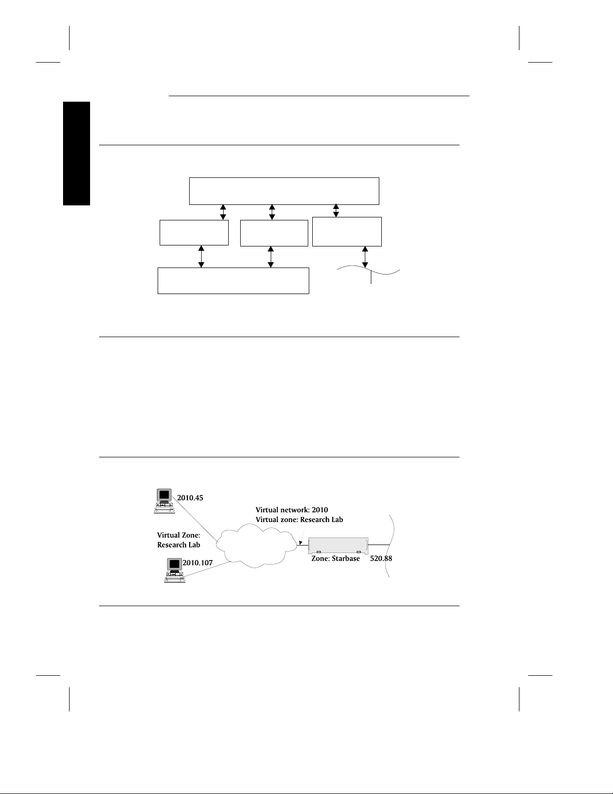
AppleTalk Network Number and Zone Assignment
The LCS60 supports dynamic AppleTalk address assignment within a virtual zone
of PPP and ARAP clients. (Refer to Figure 1-2.) Upon dialing into the LCS60, the
PPP client is assigned an available network and node number automatically. The
client then becomes part of the virtual zone configured on the LCS60; no special
dialstring options are used.
Figure 1-2: AppleTalk Virtual Zone
Mac
Lucent Data Switch
Network
Mac
1-8 Issue 3
LCS60
Page 31

LAN Protocols
Note: It is not necessary to configure the LCS60’s Ethernet interface for
AppleTalk. The LCS60 is not a seed router on the Ethernet. It will
discover the network range and the zones assigned to the Ethernet by
another router and will dynamically acquire a unique AppleTalk node
address within the assigned network number range.
IPX Protocol
The IPX protocol is used to connect hosts in a Novell network.
The LCS60 can be used as an IPX router connecting the Ethernet LAN to a virtual
IPX network via PPP. The virtual IPX network created by the LCS60 permits as
many as 120 remote end hosts to dial in over the data switch and connect to the
Novell network. The virtual network on the LCS60 supports a single network
number.
IPX Virtual Network Assignment
The LCS60 supports dynamic address assignment within a virtual network of IPX
over PPP clients. (Refer to Figure 1-3.) Upon dialing into the LCS60, the PPP
client is assigned an available IPX address automatically. The client then
becomes part of the virtual IPX network configured on the LCS60; no special
dialstring options are used.
Features
Figure 1-3: IPX Virtual Network
Lucent Data Switch
Network
Issue 3 1-9
LCS60
Page 32

Remote Access Protocols
TCP/Async Gateway Service
The LCS60 provides a gateway service such that a terminal user connected to the
Features
data switch network either directly or through a modem can reach LANconnected hosts/workstations – this is the async-to-TCP gateway service. The
LCS60 provides communication in the other direction – from the LAN-host to
the data switch – with the TCP-to-async gateway service.
This connectivity is accomplished through the telnet and tcpsock commands
which allow communication between the data switch and LAN-host by means of
the TELNET protocol. Some features of this service are:
File Transfer. The LCS60 provides a mechanism for data switch to LAN
and LAN to data switch file transfer. A host connected to the data switch
network or to the LAN can initiate a file transfer (such as a uucp file
transfer) by including the dialstring for the LCS60 in its system files and
requesting TCP socket service. Both services provide an 8-bit TCP pipe as a
path for large file transfers; this pipe bypasses telnet which is slower.
Break character. The LCS60 recognizes the data-switch connected user’s
break character and converts it into a telnet IAC break character. From
the LAN, the LCS60 converts the telnet IAC BREAK sequence into an
URP* Level-D break toward the data switch connection.
Security. The LCS60 can be configured to drop the telnet connection if the
host to which the user is trying to telnet is unavailable. Without this
feature, trying to reach an unavailable host would result in putting the
user at the telnet> prompt and could possibly allow unauthorized connection to other LAN hosts. With this security feature, the connection is
taken down completely if the host is unavailable.
The LCS60 provides as many as 500 simultaneous telnet sessions (when no
PPP/SLIP/ARAP sessions are configured), which may be distributed in any way
between TCP-to-async and async-to-TCP sessions.
Note: Simultaneous sessions are not necessarily all active.
Details of the telnet service are given in Chapter 7.
* Refer to the CommKit Internal Interface Specification for details of the Universal Re-
ceiver Protocol (URP).
1-10 Issue 3
Page 33

Remote Access Protocols
The TCP gateway sessions take advantage of the highly efficient fiber interface
between the LCS60 and the data switch. With this service, any TCP/IP host that
can be reached on the LAN is accessible from the data switch network. For LAN
users, connection is generally provided through a DESTINATION: prompt, however, a TCP service port can be customized to bypass this prompt and automatically connect the LAN user directly to a particular data switch end point.
Refer to Chapter 7 for configuration of gateway services.
TCP Service Ports
A TCP service port is identified by a port number and can be customized to
streamline the transition from the TCP/IP network to the data switch network.
These ports can be configured with predefined destinations (PDDs), disconnect
options, window size changes, time limit options for the DESTINATION: prompt
and for data transmission, and customized destination prompts.
The number of TCP service ports is 500; each port can be defined with a unique
PDD offering the administrator enhanced flexibility in terms of the number of
data switch network connected hosts than can be contacted by each LCS60.
Features
Serial Line IP (SLIP)
The LCS60 provides SLIP protocol capability to enhance dial-in access through
the data switch network. SLIP enables remote users to gain access to their internet and use familiar TCP/IP commands for most applications, e.g., file transfer,
electronic mail, and remote login.
SLIP allows a remote PC or Macintosh to logically reside on the TCP/IP LAN. In
a SLIP session, a remote user can dial into an LCS60, request SLIP service, and
receive an IP address automatically. This remote user is then logically connected
to the LAN and can execute such TCP/IP commands as ftp, telnet, and ping.
With the capability for automatic assignment of IP addresses, the LCS60 maintains a database of used addresses and the LCS60 administrator does not have to
pre-assign IP addresses to users. Static assignment of these addresses is still possible, however, for any situation where it may be necessary.
Issue 3 1-11
Page 34

Remote Access Protocols
The total combined number of remote access sessions – when SLIP, PPP, and/or
ARAP are configured – available through the LCS60 is 120.
Refer to Chapter 5 for configuration of the LCS60 for SLIP service.
Features
Point-to-Point Protocol (PPP)
PPP provides point-to-point connectivity between a remote PC or Macintosh and
a LAN host, and is the industry standard. It is designed to carry multiple protocols such as TCP/IP, XNS, IPX, AppleTalk, and DECnet.
The remote PC or Macintosh negotiates the PPP protocol options with the LCS60
through the client software package residing on the PC or Mac. A remote user
can dial into the LCS60 through the data switch, request PPP service, and receive
an IP address, IPX address, and/or AppleTalk network and node number
automatically.
For TCP/IP, the IP address can be statically assigned, if needed (as it can be with
SLIP), and gives the remote user access to the TCP/IP network via commands
such as ftp, telnet, and ping.
For AppleTalk, a virtual AppleTalk address is assigned enabling the remote user
to access AppleShare and remote printer spooling services in various zones in
the network.
For IPX, a virtual IPX address is assigned. The remote user is viewed as a Novell
NetWare client and can therefore access file servers, printer servers, etc., in a
Novell network.
Refer to Chapter 4 for configuration of the LCS60 for PPP service.
Van Jacobson TCP/IP Header Compression
Negotiation of the TCP/IP header compression option is defined in RFC1332. If
your client package supports Van Jacobson Header Compression, then configure
this feature on your Mac or PC. The size of each packet can shrink up to 35
bytes, thereby giving your PPP session a significant performance boost.
1-12 Issue 3
Page 35

Remote Access Protocols
Compressed IPX Header (CIPX)
Negotiation of the IPX header compression option is defined in RFC1553. If your
client package supports Compressed IPX Headers (CIPX), then configure this
feature on your PC. The size of each packet can shrink up to 34 bytes, thereby
giving your PPP session a significant performance boost.
AppleTalk Remote Access Protocol (ARAP)
ARAP is used to obtain direct access to AppleTalk resources at remote locations.
The LCS60 uses ARAP to provide connection between the CommKit Host Interface and Ethernet-connected AppleTalk devices.
A remote user can dial into the LCS60 through the data switch, request ARAP
service, and receive the AppleTalk network and node number automatically.
The remote user can access AppleShare and remote printer spooling services in
various zones in the network.
Refer to Chapter 6 for configuration of the LCS60 for ARAP service.
Features
Multiple IP Subnetworks
IP Routing
The LCS60 acts as an IP router with multiple IP network interfaces. Figure 1-4
shows an example of how an LCS60 might be configured, defining four virtual IP
subnetworks. Each interface has a unique IP subnetwork number that represents
a LAN segment. These numbers are allocated by the Network Administrator
during configuration of the LCS60.
Issue 3 1-13
Page 36

Multiple IP Subnetworks
Figure 1-4: IP Routing with the LCS60
Features
LAN Segment
Security Group: Library
(virtual)
154.12.24
Ethernet LAN
morse-e0
(physical)
154.12.21
LCS60
morse
LAN Segment
Security Group: morse
(virtual)
135.12.23
Security Group:Eng
LAN Segment
Security Group: Techs
(virtual)
154.12.25
CommKit Host Interface
Note: The numbers shown are IP network numbers.
The LCS60 reserves host address .1 for
each virtual LAN segment (e.g., 154.12.24.1).
LAN Segment
(virtual)
154.12.26
Lucent Data Switch
Network
.1
The LCS60 has a physical IP network number for its Ethernet interface (e.g.,
154.12.21) and can have a virtual IP network number for each defined security
group (e.g., Library, morse, Techs, Eng), up to a maximum of four such groups
as shown in Figure 1-4.
Note: The Ethernet IP network number and the four virtual IP network
numbers must be unique.
The LCS60 examines the destination address of every IP packet it receives over
the Ethernet and CommKit Host interfaces, and sends the packet on to the LAN
segment it matches. For this reason, all network numbers must be unique. For
example, for an IP packet with a destination address 154.12.24.50, the LCS60
morse would route the packet through LAN segment Library as shown in Figure
1-4.
1-14 Issue 3
Page 37

Multiple IP Subnetworks
Security Groups
The LCS60 provides a mechanism for allocating IP addresses from one or more
pools of addresses. Each address pool is associated with a unique IP network
security group and is used to limit user access to the LAN.
This feature allows the LCS60 administrator to define up to four IP networks that
an LCS60 user can select when dialing in for either SLIP service or IP over PPP
service. Each IP network is associated one for one with a dkserver service name.
This name must be entered in the following databases:
LCS60 in which the dkserver name is referred to as an IP network security
group. One of these IP network security groups is required to match the
UNIX node uname value.
Data switch controller database as a local CPM host address, all associated
with the same CPM group.
Network Access Controller (NAC) as a host name (if security is required).
The NAC database is used to authorize members of a particular user group to
create calls to the LCS60 host name represented by the IP network security group
name. Generally, all those users who share common IP network access privileges
are assigned to a NAC user group; the NAC is set up to present the group
members a menu of LCS60 hosts they are permitted to call.
Features
The IP routers connected to the same Ethernet LAN as an LCS60 are configured
to filter/secure IP traffic flow on the basis of an arriving packet’s source IP network address. A user’s source IP address is assigned by the LCS60 (or subject to
verification, it can be nominated by the user) when the SLIP or PPP session is
started.
An LCS60 is required to have an IP network security group whose name matches
the LCS60’s UNIX node name; this is referred to as the uname IP network security group. As a consequence, the ipas script requests that you configure the
uname security group’s IP network address before you are allowed to add any
other IP network security group. When editing the uname IP network security
group, the ipas script prevents you from altering its name; if you want to edit
this attribute, use the nodename script. Any change in the UNIX node name is
automatically applied to the uname IP network security group name and any of
its associated reserved IP addresses. You are not allowed to delete the uname IP
network security group because other LCS60 services depend on its dkserver
process being present.
Issue 3 1-15
Page 38

Multiple IP Subnetworks
Figure 1-5: IP Address Assignment
Features
Incoming Call
IP address
privately
administered
on PC?
N
Was user
ID specified on
dialstring?
N
Set user id
to "guest"
-D option
on dialstring?
Y
Assign
dynamic
IP address
Is this
IP address out
of range?
N
Is this
Y
IP address
busy?
N
Error: IP address
Y
Error: IP address
Y
is not available
is not correct
Is this
Y
reserved?
N
IP address
Y
Error: IP address
is reserved
Grant
requested IP
address
Search for
reserved IP address
with IP Network
N
security group name
and user ID name
N
Find a
reserved IP
address?
Y
Is the
reserved IP
address
busy?
Y
N
assign reserved
IP address
Error: IP address
is busy
1-16 Issue 3
Page 39

Multiple IP Subnetworks
IP Address Assignment by the LCS60
PPP and SLIP users need to be assigned an IP address when they connect to the
LCS60, thereby allowing them to run TCP/IP applications over their serial connection. Figure 1-5 describes IP address assignment; refer to Chapter 4 (PPP) or
Chapter 5 (SLIP) for more information.
Note: IP address assignment is defined in RFC1332.
The LCS60 has three mechanisms for assigning a SLIP or PPP user an IP address:
1 . Privately Administered Static IP Address. The user’s IP address is locally
administered by the user on his/her PC software package. The LCS60
will use the IP address requested by the PC package if it is valid and
unused.
2 . Reserved IP Address. This IP address, administered by the LCS60 adminis-
trator, is requested by specifying a zero IP address on the client software
package. A reserved IP address must exist in the LCS60 configuration
database before the session start up attempt.
3 . Dynamically Assigned IP Address. This IP address is randomly assigned by
the LCS60 from the IP network range associated with the particular IP
Network Security Group. A dynamic address may be requested on the
dialstring if no reserved IP address exists for a user ID.
Features
Hardware Features
Enhanced Processor
The LCS60 offers the enhanced Motorola MVME197 processor, rated at 100+
MIPS. With this processor, the LCS60 can sustain a higher number of sessions at
a greater aggregate throughput than its LCS50E predecessor.
Issue 3 1-17
Page 40

Hardware Features
Fiber Interface
The LCS60 supports a single multiplexed fiber interface to the data switch CPMHS module. This is a distinct advantage in terms of cable management and effi-
Features
ciency over traditional terminal servers which require separate asynchronous
connections.
Network Security
Complete network security is achieved through the Lucent Technologies Network Access Control (NAC) System. When a data-switch connected modem
accepts a call from a remote user, a PDD can force that user to authenticate
through a NAC. Once authenticated, the user can request a TCP gateway session
or a remote access session (such as ARAP, PPP, or SLIP) with an LCS60 by means
of a simple dialstring. From the LAN, all sessions bound for the data switch network can be forced to be authenticated by means of the TCP service port feature.
Additionally, the LCS60 supports a first-time authentication option with the
NAC. This option requires the LAN users to authenticate only once with the
NAC as long as the TCP/Async session remains open with the LCS60. The
actual duration time of an authenticated session is a NAC-dependent variable.
Therefore, consult the NAC documentation (refer to the section Reference Docu-
mentation in this chapter) for complete details on this feature.
1-18 Issue 3
Page 41

Copy Protection
This release of the LCS60 is copy-protected and requires a personalized software
key before it can be used. This number is assigned during the initial setup of the
LCS60 using the lcsadm interface (refer to Chapter 3 for complete details). The
copy-protection feature uses a release-specific software key; that is, Release 3 services can only be activated using the Release 3 key.
Administration
The LCS60 has its own local management software package called lcsadm. This
package allows a network administrator to configure services, administer service
sessions, and collect performance measurement data. This administration tool
can be accessed either through the LCS60 console port or through the multiplexed fiber interface.
Note: The remote administration feature is delivered in the disabled state.
Instructions for enabling this feature are given in Chapter 8.
Features
Backup/Restore
The LCS60 provides a backup/restore feature that allows an LCS60 to be configured as a backup/restore server. A backup/restore server can copy to its hard
disk (i.e., back up) a predefined set of files/directories from multiple remote
LCS60s (and LCS50Es) which are configured as backup/restore clients. The
backup/restore server can also be configured as its own client.
Note: LCS60 R1.0 backups cannot be used to restore R3.0 systems.
The remote backup of clients is done disk-to-disk over the data switch network.
Backups and restores may be initiated either from a server or from a client.
This feature allows multiple backups of configuration files to be stored, and any
of several stored backups may be selected to be restored. Restores may be
comprehensive or selective, as required.
Issue 3 1-19
Page 42

Administration
R3.0 Upgrade
Previous releases of the LCS60 can be upgraded to Release 3.0. This requires
removing the software and any patches for the earlier release and installing the
Features
R3.0 software from tape. Upgrade procedures are given in Chapter 9.
The configuration is automatically restored after installing R3.0; the user need
only configure new or changed services.
Note: When upgrading from R1.0 or R2.0 to R3.0, you must have an R3.0
software key to activate R3.0 features. Refer to the section on Copy Pro-
tection.
Remote Upgrade
Upgrading multiple LCS60s to release 3.0 or greater can be done using the
remote upgrade feature. To upgrade several LCS60s to release 3.0 or greater, the
local tape drive need only be used to install the upgrade release on a single
LCS60 (the remote upgrade server). All other R2.0 or greater LCS60s in your
data switch network (remote upgrade clients) may then be upgraded remotely
across the data switch network.
Centralized Network Management
StarKeeper II NMS provides complete network management from one centralized location for both the data switch and the LCS60. The StarKeeper II NMS can
be located anywhere on the data switch network and can contact many LCS60
gateways.
1-20 Issue 3
Page 43

Manual Pages
The LCS60 is provided with a set of online manual pages. Some commands that
may be of particular help to the system administrator are listed in Table 1-1 and
are included in Appendix E.
Features
Table 1-1: Online Manual Pages
_ _______________________________________________
_ _______________________________________________
Protocol Commands Path
_ _______________________________________________
General dkcu /opt/dk/bin/dkcu
_ _______________________________________________
TCP/IP ftp /usr/etc/ftp
_ _______________________________________________
AppleTalk atlog /usr/etc/atlog
_ _______________________________________________
IPX ipxping /usr/etc/ipxping
_ _______________________________________________
dkmaint /opt/dk/sbin/dkmaint
ifstat /usr/bin/ifstat
iftrace /usr/etc/iftrace
push /usr/bin/push
pull /usr/bin/pull
statlcs /usr/etc/statlcs
ifconfig /usr/etc/ifconfig
netstat /usr/etc/netstat
nslookup /usr/etc/nslookup
ping /usr/etc/ping
route /usr/etc/route
telnet /usr/etc/telnet
atping /usr/etc/atping
atnetstat /usr/etc/atnetstat
ipxnetstat /usr/etc/ipxnetstat
The commands dkmaint and ifconfig are not used in normal LCS60 operations,
and should only be used by expert users and system administrators. These commands are not recommended except for troubleshooting purposes.
Access online man pages by executing the command:
Issue 3 1-21
Page 44

Manual Pages
# man
command
Features
where command is the name of the command.
Customer Assistance
Technical support is available for the LCS60 from the Lucent Technologies Customer Technical Support Center at 1-800-WE2CARE.
For more information on these service offerings, or to establish a service account,
contact your Lucent Technologies account representative, or call 1-800-WE2CARE during our standard business hours (8AM – 5PM Eastern Time, Monday
through Friday, excluding holidays) and ask for the Data Networking Services
Operations department.
When you need assistance, call 1-800-WE2-CARE during the coverage period
selected when you established your service account. You will need to provide
your Service Account Number and identify the specific Lucent Technologies
Data Networking product for which you need assistance.
Outside the United States, Lucent Technologies Data Networking products and
support services are provided by Lucent Technologies subsidiaries and authorized value-added resellers. For more information, contact your sales representative.
1-22 Issue 3
Page 45

2
Hardware Installation
Introduction 2-1
Controls and Indicators 2-1
Site Preparation 2-2
Space Requirements 2-4
Cabling 2-4
EMI Considerations 2-5
Required Equipment 2-5
Assembly 2-6
Unpacking 2-6
Installing the LCS60 2-6
Rack Mounting 2-6
Wall Mounting 2-8
Table-Top Mounting 2-8
Connecting the System Console 2-9
Serial Port Optioning (DTE/DCE) 2-9
Direct Connection to the LCS60 2-12
Connection through a Data Switch 2-12
Connection through Modems 2-17
Connection through StarKeeper II NMS 2-17
Connecting the Fiber Interface 2-19
Routing the Optical Fiber Cable 2-19
Installing the CPM-HS Module and Optical Fiber
Cable 2-20
Issue 3 i
Page 46

Table of Contents
Configuration of the Lucent Technologies Data
Switch – LCS60 2-21
Dialogues 2-22
Enter Group Name 2-22
Define the Local Address for the LCS60 2-22
Configure the CPM-HS Module 2-24
Power and Grounding 2-25
Power-Up Procedures 2-25
Power-Down Procedures 2-27
Verify LCS60 Console Connection 2-27
Verify Fiber Connection 2-28
Configure the LCS60 2-29
LAN Connections 2-29
Ethernet 2-29
ii Issue 3
Page 47

Introduction
The LCS60 is supplied with the operating software already installed; therefore,
installation consists mainly of installing hardware and configuring the system.
The list below identifies the tasks, in the order that they should be performed, to
install and configure the product. These tasks are discussed in detail in the following sections.
1 . Mount the LCS60
2 . Attach the console to the LCS60
3 . Connect the fiber between the LCS60 and the CPM-HS
4 . Configure the LCS60 in the data switch
5 . Power-up the LCS60
6 . Verify the LCS60 console connection
7 . Verify the LCS60 fiber connection
8 . Configure the LCS60 using the lcsadm interface (Chapters 3–7)
9 . Verify connections between the LCS60 and LAN hosts and between the
LCS60 and data switch connected endpoints (Chapter 9).
Controls and Indicators
Table 2-1 lists the LCS60 controls and indicators.
Hardware
Issue 3 2-1
Page 48

Introduction
Table 2-1: Controls and Indicators
_ _____________________________________________________________________
_ _____________________________________________________________________
_ _____________________________________________________________________
Location Switch Function
_ _____________________________________________________________________
Rear Panel Power Power ON/OFF
_ _____________________________________________________________________
MVME197 ABORT Aborts program, returns to debugger
_ _____________________________________________________________________
_ _____________________________________________________________________
Board Indicator Function
_ _____________________________________________________________________
MVME197 FAIL Hardware failure
Hardware
_ _____________________________________________________________________
MVME712M ETHERNET XCVR Ethernet Transceiver
_ _____________________________________________________________________
_ _______________________________________________________
SYSTEM RESET Processor and VME bus reset
_ _______________________________________________________
_ _______________________________________________________
_ _______________________________________________________
_ _______________________________________________________
_ _______________________________________________________
_ _______________________________________________________
_ _______________________________________________________
RESET
SCON Indicates 197 board
RUN Processor run state
LAN LAN status
VME VME status
SCSI SCSI status
PWR STATUS* power status (amber)
SCSI TERM SCSI terminator
PWR STATUS* power status (green)
Controls
Processor and VME bus reset
Indicators
is VME bus controller
*Can be seen by means of the rear panel cutout labeled SCSI INTERFACE.
Site Preparation
LCS60 specifications for the power, interface, and operating requirements, as
well as the other pertinent interface specifications, are listed in Table 2-2.
2-2 Issue 3
Page 49

Site Preparation
Table 2-2: Specifications
_ _______________________________________________________
_ _______________________________________________________
_ _______________________________________________________
Power Requirements 90 to 132 VAC (47 to 63 Hz), 5 Amps
LCS60 Network Interface for Ethernet
Operating Temperature 10 to 45°C
Storage Temperature −40 to 54°C
Operating Humidity Long-Term 20 to 55%
Storage Humidity
_ _______________________________________________________
_ _______________________________________________________
Fiber Core Size 62.5 microns
Mode Multi-mode
Fiber Optic Cable FL2P-P Type
Connector
_ _______________________________________________________
_ _______________________________________________________
Interface IEEE 802.3
Connector
_ _______________________________________________________
_ _______________________________________________________
Port 1 (console) RS-232C (limited) Asynchronous
Console/Terminal Interfaces
Ports 2,3,4 (terminal) RS-232C Asynchronous
Connectors
_ _______________________________________________________
_ _______________________________________________________
Port 1 9600 bps
Port 2 9600 bps
Port 3 9600 bps
Port 4 1200 bps
_ _______________________________________________________
180 to 250 VAC (47 to 63 Hz), 2.5 Amps
41 to 60 VDC, 8 Amps
Short-Term 20 to 80%
10 to 95%
Fiber Interface
ST Type
Ethernet Interface
Female 15-pin DB15
25-pin DB25 (receptacle)
Serial Port Defaults
Hardware
Issue 3 2-3
Page 50

Site Preparation
Space Requirements
The LCS60 can be rack mounted, wall mounted, or installed on a secure surface.
The unit is 7 × 17 × 19 inches and weighs 40 lbs. A minimum of 12 inches of
clearance is required at the front and rear of the unit for access, and a minimum
of two inches of clearance at the sides of the unit to permit proper airflow
through the unit.
Cabling
WARNING: Connect and disconnect cables ONLY when the power is off.
Hardware
There are four types of connections commonly required for the LCS60:
1 . A dual optical fiber connection to a CPM-HS module installed in a Lucent
Technologies data switch or concentrator. The fiber cable between the
LCS60 and the data switch is limited to a maximum length of 2.9 km.
2 . Ethernet LAN connection.
3 . A console connection through an RS-232C interface to either a terminal or
data switch port. RS-232 distance limits apply to the LCS60 console con-
nection (nominally 50 feet).
4 . An AC power connection is required for an AC powered unit. An AC
outlet must be within 6 feet of the LCS60; the use of extension cords
should be avoided.
5 . A DC power connection is required for DC powered units. The customer
must make this connection with wire no larger than 6 AWG and no
smaller than 18 AWG.
Cautions: Do not run signal cables next to, or parallel with, AC power cables.
Do not run signal cables near radio transmitters or any equipment
that generates radio frequencies.
Do not run signal cables near electric motors, power supplies,
power line regulators, or relays.
Do not run signal cables near equipment that generates power line
noise; such as air conditioners, copy machines, and water coolers.
Use power outlets with adequate protective grounding.
2-4 Issue 3
Page 51

Site Preparation
EMI Considerations
The LCS60 can radiate radio frequency energy, and if not installed in accordance
with instructions, may cause interference to radio communications. This equip-
ment has been tested and found to comply with the limits for a Class A comput-
ing device pursuant to Part 15, Subpart J of FCC Regulations, which are designed
to provide reasonable protection against such interference when operating in a
commercial environment. Operation in a residential area is likely to cause
interference, in which case the user must take whatever measures may be
required to correct the interference.
Required Equipment
The LCS60 is shipped in the hardware configuration ordered, the operating
software loaded, and user documentation included. Additional equipment
required for the initial installation of an LCS60 is listed in Table 2-3.
Table 2-3: Required Additional Equipment
_ __________________________________________________________________
_ __________________________________________________________________
Quantity Item Description
_ __________________________________________________________________
_ __________________________________________________________________
_ __________________________________________________________________
_ __________________________________________________________________
(as reqd.) Horizontal Shelf, Rack mounting hardware for additional
_ __________________________________________________________________
1 (as reqd.) ED5P183-33, G-40 Wall Mounting Kit for LCS60
_ __________________________________________________________________
_ __________________________________________________________________
_ __________________________________________________________________
(as reqd.) wire 18 AWG— 6 AWG wire for DC powered unit only
_ __________________________________________________________________
1 Fiber Pair Lucent FL2P-P-[length]* (specified in feet)
1 RS-232 Length required to connect console to
(DB25) Cable LCS60
1 Ethernet Transceiver Length required for connection from
(IEEE Cable) LCS60 to Ethernet transceiver
Slide Rails, or support; provided by rack/cabinet
support brackets vendor.
1 CPM-HS module Node connection
1 AWJ2 Paddleboard for the CPM-HS module
Hardware
* Formerly AT&T FL2P-P.
Issue 3 2-5
Page 52

Assembly
Unpacking
The LCS60 hardware comes fully assembled, with the exception of two handles
that mount on the front frame of the enclosure. After opening the shipping container, remove the documentation package, system software tapes and diskettes
and package of loose parts. Carefully remove the LCS60 unit. Open the front
cover of the LCS60 and check that the system is equipped as ordered and that all
circuit packs are fully seated in the LCS60 card cage.
Hardware
Installing the LCS60
Follow the appropriate instructions (refer to Figure 2-1) to install the LCS60.
Rack Mounting
Mount the LCS60 in a 19-inch rack or cabinet using compatible mounting
hardware as shown in Figure 2-1. Mounting in a 23- or 25-inch rack or cabinet
requires a Bracket Extension Kit.
The front frame of the LCS60 has four mounting holes for securing the unit in a
standard 19-inch equipment rack. The weight of the LCS60 requires a shelf, slide
rails, or a support bracket. Contact the cabinet vendor for compatible hardware.
The handles for the LCS60 are shipped in a separate package within the main
shipping box. The handles can be attached to the front frame, with the handles
pointing away from the LCS60, using the four flat-head machine screws.
To rack mount the unit:
1 . Attach either a horizontal shelf, slide rails, or support brackets to the verti-
cal uprights of the cabinet. For design compatibility, this hardware
should be purchased from the cabinet vendor.
2-6 Issue 3
Page 53

Installing the LCS60
2 . With the horizontal support in place, slide the LCS60 into place. Fasten
the front frame of the LCS60 to the front uprights with four screws (23- or
25-inch cabinets require extension brackets).
Figure 2-1: Mounting the LCS60 Cabinet
.
.
.
.
TOP
.
.
.
.
.
.
.
.
.
.
.
.
.
.
.
.
.
. . . . .
.
BOTTOM
. .
. .
Wall Mount Assy.
mounts to wall
Front
Frame
Cabinet
Rear uprights
Disk and tape drives
must be on top
. .
.
.
.
.
.
.
.
.
.
.
.
. .
LCS60 mounts inside
Wall Mount Assembly
Hardware
WALL
WALL MOUNT
Front
Horizontal shelf,
slide rails, or
Cabinet
Front Uprights
support brackets
required
TABLE TOP MOUNTRACK MOUNT
Issue 3 2-7
Page 54

Installing the LCS60
Wall Mounting
Wall mounting the LCS60 requires a Wall Mount Assembly to position the unit
vertically as shown in Figure 2-1.
Wall mounting requires a surface 45 inches wide by 21 inches high covered by a
securely-fastened ¾-inch plywood sheet (or a comparably stable mounting surface).
The handles for the LCS60 are shipped in a separate package within the main
shipping box. If desired, attach the handles to the front frame, with the handles
pointing away from the LCS60, using the four flat-head machine screws.
To wall mount the unit:
Hardware
1 . Using the Wall Mounting Assembly as a template, mark the location of
the four mounting holes on the plywood sheet. Drill the pilot holes or
install appropriate anchors, as required.
Note: To function properly, the LCS60 must be positioned in the Wall Mount
Assembly with the disk and tape drive on top, the bottom surface
toward the wall, and the front cover of the LCS60 to the left.
2 . Attach the Wall Mounting Assembly to the plywood surface, using four ¼
x ¾-inch lag screws.
3 . Locate the LCS60 in the mounting assembly by aligning the front flange of
the LCS60 with the four threaded holes on the flange at the left end (facing
the assembly). Secure the LCS60 to the assembly, using the four M6 x
12mm screws included with the Wall Mount Assembly.
Table-Top Mounting
The handles for the LCS60 are shipped in a separate package within the main
shipping box. Attach the handles to the front frame, with the handles pointing
away from the LCS60, using the four flat-head machine screws.
Install the LCS60 on a stable surface with the required clearance as described previously under Space Requirements.
2-8 Issue 3
Page 55

Installing the LCS60
Connecting the System Console
WARNING: Connect and disconnect cables ONLY when the power is off.
The LCS60 uses a system console to run diagnostics, receive error messages, and
for administration. Configure the console as shown in Table 2-4.
Table 2-4: System Console (and Port) Configuration
The LCS60 has four serial RS-232 ports which can emulate asynchronous DTE or
DCE. Serial Port 1 is used for the LCS60 system console and operates at 9600
bps. Ports 2, 3, and 4 can be used to interface asynchronous terminals to the
LCS60 UNIX System with Ports 2 and 3 providing 9600 bps operation and Port 4
providing 1200 bps operation. The system console must be an asynchronous
ASCII terminal or PC (with terminal emulator). We recommend using a system
console with scrolling capability. The system console can be connected directly,
through a Lucent Technologies data switch, through modems (9600 bps), or
through StarKeeper II NMS.
Connect the system console to the LCS60 using one of the four connection
methods described in the following sections.
_ _________________________________
_ _________________________________
Baud Rate 9600 bps
_ _________________________________
Flow Control XON/XOFF
_ _________________________________
Data Bits 8, no parity
_ _________________________________
Stop Bits 1
_ _________________________________
Local Echo None (full duplex)
_ _________________________________
Serial Port Optioning (DTE/DCE)
Direct- and network-connected system consoles require Serial Port 1 to be
optioned to emulate DCE for connection to an external DTE device (this is the
default). If connection is through modems (DCE), Serial Port 1 must be optioned
to emulate DTE. Refer to Figure 2-2 and Table 2-5 for optioning information; see
Table 2-6 for DTE and DCE emulation and pin assignments for RS-232C inter-
faces.
Hardware
Issue 3 2-9
Page 56

Installing the LCS60
Table 2-5: MVME712M Module Optioning
_ ____________________________________________________
_ ____________________________________________________
Hardware
_ ____________________________________________________
Ext.Interface Port Emulation Port Jumper Bridged Pins
_ ____________________________________________________
DTE DCE 1 J1 all
_ ____________________________________________________
DTE DCE 2 J16 all
_ ____________________________________________________
DTE DCE 3 J13 all
_ ____________________________________________________
DCE DTE 4 J19 all
_ ____________________________________________________
_ ____________________________________________________
_ ____________________________________________________
DCE DTE 1 J11 all
_ ____________________________________________________
DCE DTE 2 J17 all
_ ____________________________________________________
DCE DTE 3 J14 all
_ ____________________________________________________
DTE DCE 4 J18 all
_ ____________________________________________________
_ ____________________________________________________
Default Optioning
Non-Default Optioning
J15
no jumpers
J15 no jumpers
Figure 2-2: MVME712M Header Locations and Factory Jumper Placements
J11
2 14
•••
•
•
•••••
•
•
1
J1
2
1
R2
R1
13
25
13
25
J14
2
14
•
•
14
13
J7 J8
J9 J10
• •••••
•••
1
•
•••
•
J13
2
1
R3 R4
1
14
1
14
2 J20 20
•
•
1 19
2
•
•
•
•
13141
14
2
13
1
2
•
•••••
1
•
•
J17
•
•
J15
•
•
•
•••••
J16
•
•
13
25
13
25
•
•
•
13141
14
13
12
•
•••
11
•••••••••••••
2
2
•••
1
R5
1
14
1
14
J21 6
1
• • • • • •
J19
13 13
J18
14
•
•
•
•••••••
•
13
DS1 DS2
15
2
•
•
•
1
C1 C32
R6
49
50
1
8
0
J6
•
•
•
•
•
•
•••
•••••••••••
•
•
C1R7
1 8 1 R8 8 1 R9 R10 8
18
36
•••••••••••••••
J3
J2
C2 C3
•
•••
•••
•
•
•
50
49
A32 A1
1
2
J5
1
19
2-10 Issue 3
Page 57

Installing the LCS60
Table 2-6: RS-232 Interface
_ __________________________________________________________________
_ __________________________________________________________________
_ __________________________________________________________________
Port 1 2 BA TD-Transmit Data To DCE
Async DTE 4 CA RTS-Request To Send To DCE
Emulation 7 AB Signal Ground
_ __________________________________________________________________
_ __________________________________________________________________
Port1 2 BA TD-Transmit Data From DTE
Async DCE 4 CA RTS-Request To Send From DTE
Emulation 6 CC DSR-Data Set Ready To DTE
_ __________________________________________________________________
_ __________________________________________________________________
Ports 2, 3, 2 BA TD-Transmit Data To DCE
and 4 4 CA RTS-Request To Send To DCE
Async DTE 7 AB Signal Ground
Emulation 20 CD DTR-Data Terminal Ready To DCE
_ __________________________________________________________________
_ __________________________________________________________________
Ports 2, 3, 2 BA TD-Transmit Data From DTE
and 4 4 CA RTS-Request To Send From DTE
Async DCE 6 CC DSR-Data Set Ready To DTE
Emulation 8 CF DCD-Data Carrier Detect To DTE
_ __________________________________________________________________
Pin Designation Function Direction
3 BB RD-Receive Data From DCE
5 CB CTS-Clear To Send From DCE
20 CD DTR-Data Terminal Ready To DCE
Pin Designation Function Direction
3 BB RD-Receive Data To DTE
5 CB CTS-Clear To Send To DTE
7 AB Signal Ground
8 CF DCD-Data Carrier Detect To DTE
Pin Designation Function Direction
3 BB RD-Receive Data From DCE
5 CB CTS-Clear To Send From DCE
8 CF DCD-Data Carrier Detect From DCE
Pin Designation Function Direction
3 BB RD-Receive Data To DTE
5 CB CTS-Clear To Send To DTE
7 AB Signal Ground
20 CD DTR-Data Terminal Ready From DTE
Hardware
Issue 3 2-11
Page 58

Installing the LCS60
Asynchronous
Direct Connection to the LCS60
To connect an asynchronous terminal or PC directly to the LCS60 for use as an
LCS60 console, refer to Figure 2-3 and follow the steps below:
1 . Serial Port 1 should be optioned to emulate DCE operation. This is the
default; therefore, if you haven’t changed anything there will be no need
to change the option.
2 . Connect a 25-pin RS-232 cable between the LCS60 rear panel connector
labeled "Serial Port 1" and an asynchronous terminal or PC (Figure 2-7).
3 . Power-up the system console and set the options as directed in Table 2-4.
4 . Continue with the Connecting Fiber Interface section.
Hardware
Figure 2-3: System Console Connections – Direct
Terminal
DCE
Console
Port
LCS60
Connection through a Data Switch
To connect an asynchronous terminal or PC to the LCS60 for use as a system console through a data switch network, refer to Figure 2-4 and follow the steps
below:
Note: Connections to the data switch network must be to an asynchronous port
(e.g., a TY-12 port).
2-12 Issue 3
Page 59

Installing the LCS60
1 . Serial Port 1 should be optioned to emulate DCE operation. This is the
default; therefore, if you haven’t changed anything there will be no need
to change the option.
2 . Connect the LCS60 rear panel connector labeled "Serial Port 1" to an asyn-
chronous port using a straight-through connection (D8AH connector);
connect the 25-pin end to the LCS60.
3 . Configure the asynchronous port on the data switch according to Table
2-4 as a receiving group. Conduct the dialogues shown in Screen 2-1 or
2-2 on the data switch console to:
a . Configure a group on the data switch network for the asynchronous port
connected to the LCS60
b . Configure a name pointing to this group which can be used to access the
LCS60 console port. (Refer to the appropriate Lucent Technologies data
switch Node Reference Guide for complete instructions.)
Note: If you already have a terminal attached to the data switch that has a DES-
TINATION prompt, skip to step 7.
Screen 2-1: TY Configuration Dialogue
CC0> enter group
GROUP [up to 8 chars]: gmorscon
TYPE [local, trunk: +(local)]: local
DIRECTION [originate, receive, 2way]: receive
DEVICE OR HOST [up to 8 chars]: morscon
HOST AUTOBAUD [on, off: +(off)]: off
ROUND ROBIN SERVICE [per_port, per_module, none: +(none)]: Return
Creating New Host: morscon
GROUP [up to 8 chars]: Delete
CC0> enter ty
TY TYPE [12 or ba12]: 12
MODULE ADDRESS: 18
Hardware
Issue 3 2-13
Page 60

Installing the LCS60
Screen 2-1: continued
PORT NUMBER [1-12: +(1-12)]: 11
COMMENT [up to 60 chars double quoted]:
"console for lcs60 morse"
SERVICE TYPE[console, dialer, host, modem, 2way, or terminal:+(terminal)]: console
GROUP [up to 8 chars]: gmorscon
BAUD RATE [300, 1200, 9600, ext, auto: +(9600)]: Return
EXTERNAL BAUD RATE [2400, 4800, 19200: +(2400)]: Return
PARITY [off, even, odd: +(off)]: Return
FLOW CONTROL OF TY-12 BY DEVICE [xon_xoff, eia, none: +(none)]: Return
FLOW CONTROL OF DEVICE BY TY-12 [xon_xoff, eia, none: +(xon_xoff)]: Return
IS AN AT&T VDM CONNECTED TO THIS LINE [yes, no: +(no)]: Return
TY TYPE [12 or ba12]: Delete
CC0> enter address
Hardware
LEVEL [local, area, exchange, local, speedcall: +(local)]: local
TYPE [numeric, mnemonic, both: +(mnemonic)]: Return
MNEMONIC ADDRESS [up to 8 chars]: morscon
PAD SUPPORT [yes, no: +(no)]: Return
DIRECTORY ENTRY [up to 30 chars double quoted, none: +(none)]:
"console to morse"
GROUP(S) [up to 4 groups separated by commas, none: +(none)]:
gmorscon
ORIGINATING GROUP NAME SECURITY PATTERN(S)
[comma-separated pattern list, same_as, none: +(none)]: Return
INITIAL SERVICE STATE [in, out: +(out)]: in
LEVEL [network, area, exchange, local, speedcall: +(local)]: Delete
CC0> restore ty
MODULE ADDRESS: 18
PORT NUMBER [1-12]: 11
CC0>
Screen 2-2: MSM Configuration Dialogue
CC0> enter group
GROUP [up to 8 chars]: gmorscon
TYPE [local, trunk: +(local)]: local
2-14 Issue 3
Page 61

Screen 2-2: continued
DIRECTION [originate, receive, 2way]: receive
DEVICE OR HOST [up to 8 chars: +(standard)]: morscon
HOST AUTOBAUD [on, off: +(off)]: off
ROUND ROBIN SERVICE [per_port, per_module, none: +(none)]: Return
Creating New Host: morscon
CC0> enter msm
COMPONENT [module, port]]: p
MODULE ADDRESS: 18
PORT NUMBER [1-12: +(1-12)]: 11
CC0> enter group
GROUP [up to 8 chars]: gmorscon
CONNECTED TO 2-WIRE MODEM [yes, no: +(no)]: Return
BAUD RATE [75, 110, 150, 300, 1200, 2400, 4800, 9600, 14400
19200, 28800, 38400, 57600, 76800, 115200: +(9600)]: Return
PARITY [off, even, odd: +(off)]: Return
FLOW CONTROL OF MSM BY DEVICE [xon_xoff, eia, none: +(eia)]: none
FLOW CONTROL OF DEVICE BY MSM [xon_xoff, eia, none: +(eia)]: xon
VDM ON THIS PORT [yes, no: +(no)]: Return
PERMANENTLY ACTIVATED PORT [yes, no: +(no)]: y
BITS PER CHARACTER [5, 6, 7, 8: +(8)]: Return
NUMBER OF STOP BITS [1, 1.5, 2: +(1)]: Return
ENDPOINT NUMBER OR RANGE [0000-9999, none: +(none)]: Return
PORT NUMBER [1-12: +(1-12)]: Delete
CC0> enter address
LEVEL [local, area, exchange, local, speedcall: +(local)]: local
TYPE [numeric, mnemonic, both: +(mnemonic)]: Return
MNEMONIC ADDRESS [up to 8 chars]: morscon
PAD SUPPORT [yes, no: +(no)]: Return
DIRECTORY ENTRY [up to 30 chars double quoted, none: +(none)]:
"console to morse"
GROUP(S) [up to 4 groups separated by commas, none: +(none)]:
gmorscon
ORIGINATING GROUP NAME SECURITY PATTERN(S)
[comma-separated pattern list, same_as, none: +(none)]: Return
INITIAL SERVICE STATE [in, out: +(out)]: in
LEVEL [network, area, exchange, local, speedcall: +(local)]: Delete
CC0> restore msm
COMPONENT [module, port]]: p
MODULE ADDRESS: 18
PORT NUMBER [1-12: +(1-12)]: 11
CC0>
Installing the LCS60
Hardware
Issue 3 2-15
Page 62

Installing the LCS60
Asynchronous
Port
Note: There are small variations in system prompts and responses depending
on the release of the Lucent Technologies data switch (Datakit II VCS or
BNS).
4 . Power-up the system console terminal or PC and set the options as
directed in Table 2-4.
5 . Connect an asynchronous terminal or PC to an asynchronous port on the
data switch, using a null-modem connection (D8AG connector). A gender
changer may be required depending on the type of RS-232 connector
available on the terminal device. Configure the asynchronous port
according to Table 2-4 as an originating group. Refer to the appropriate
Lucent Technologies data switch Node Reference Guide for complete
Hardware
instructions.
6 . Restore both asynchronous ports and name to service.
7 . In response to the DESTINATION prompt on the terminal device, enter the
name created for the LCS60 console. This step can be done from any ter-
minal displaying a DESTINATION prompt. Maintain proper security pre-
cautions to guard against unauthorized or accidental usage.
8 . Continue with the Connecting Fiber Interface section.
Figure 2-4: System Console Connections – through a Data Switch
Terminal
Data Switch
DCE
Console
Port
Asynchronous
2-16 Issue 3
LCS60
Page 63

Installing the LCS60
Asynchronous
Connection through Modems
To connect an asynchronous terminal or PC to the LCS60 for use as a system con-
sole by means of modems, refer to Figure 2-5 and follow the steps below:
1 . Option Serial Port 1 to emulate DTE operation. (Refer to the section Serial
Port Optioning earlier in this chapter.)
2 . Connect the LCS60 rear panel connector labeled "Serial Port 1" to an asyn-
chronous terminal by means of modems using straight-through RS-232
cabling. Modems must operate asynchronously at 9600 bps.
3 . Power up the system console and set options as directed in Table 2-4.
4 . Continue with the Connecting Fiber Interface section.
Figure 2-5: System Console Connections – through Modems
Terminal
Modem
Modem
DTE
Console
Port
LCS60
Connection through StarKeeper II NMS
Hardware
For the StarKeeper II NMS connection (Figure 2-6), follow the steps below:
1 . Serial Port 1 should be optioned to emulate DCE operation. This is the
default; therefore, if you haven’t changed anything there will be no need
to change the option.
Issue 3 2-17
Page 64

Installing the LCS60
Asynchronous
2 . Connect the LCS60 rear panel connector labeled "Serial Port 1" to an asyn-
chronous port on the data switch using a straight-through connection
(D8AH connector); connect the 25-pin end to the LCS60.
3 . Configure the asynchronous port on the data switch according to Table
2-4 as a receiving group. Conduct the dialogue shown in Screen 2-1 (TY-
12) or Screen 2-2 (MSM) on the data switch console to:
a . Configure a group on the data switch network for the asynchronous port
connected to the LCS60
b . Configure a name pointing to this group which can be used to access the
LCS60 console port.
Hardware
Refer to the appropriate Lucent Technologies data switch Node Reference
Guide for complete instructions.
4 . Restore the asynchronous port and name to service.
5 . Log on to StarKeeper II NMS; execute dkcu to the call address created for
the LCS60 console. Maintain proper security precautions to guard against
unauthorized or accidental usage.
6 . Continue with the Connecting Fiber Interface section.
Figure 2-6: System Console Connections – through StarKeeper II NMS
Terminal
Data
Switch
StarKeeper
II NMS
DCE
Console
Port
CPM-HS
Asynchronous
Port
LCS60
2-18 Issue 3
Page 65

Installing the LCS60
Connecting the Fiber Interface
Connection to the data switch network for data communications is by means of a
dual optical fiber cable. The network LCS60 fiber connection must be to a CPMHS module in a Datakit II VCS or BNS.
For network connection follow the steps below:
Routing the Optical Fiber Cable
The optical fiber cable may be run in suspended ceilings, subfloor cable runs, and
riser shafts up to 500 feet. Before routing the cable, connect rubber caps to each
end of the cable to protect it from dirt and dust during installation.
Note: Tools and hardware used to install copper wire and cable in building
duct and conduit systems are satisfactory for use in installing optical
fiber cable (such as, fish wire, woven cable grips, or rope). If woven
cable grips are used with fiber optic cables, tape them to the cable jacket
before pulling the cable.
When routing the cable, keep it away from copper riser cables. If this is not possible, install an inner liner (conduit or innerduct) to keep the cables separated.
EFT corrugated tubing (or equivalent) can be used; this tubing comes in short
lengths and can be bent.
Caution: Optical fiber cables are not intended for use in air-handling ceiling
areas unless installed in approved conduit.
When installing the cable, avoid tight pulls or tugs against sharp corners of
framework. If cables are to be installed around sharp edges of cabinetry or
framework, cover the edges with split tubing or similar material. Observe the
minimum bending radius and maximum pulling tension specifications when routing
the dual optical fiber cables. When lacing or securing the cable, use flat lacing
twine or cable ties and do not tie the cable too tightly or microbending losses
may occur. Bundles of cables should not hang or protrude into the work space.
Wrap the cables in loops not less than 6 inches in diameter.
Hardware
The optical fiber cable is not designed for conduit installation, but can be
installed in conduit if:
Issue 3 2-19
Page 66

Installing the LCS60
Cables are placed in a single conduit having not less than ¾-inch inner
diameter
The pull force on an optical fiber cable does not exceed 50 pounds per
cable.
Optical fiber cables should not be pulled through more than four 90-degree
bends, if more than four such bends are required, provide intermediate help
points. The minimum recommended conduit bend radius is 4-½ inches. Under
no circumstances should the cable be pulled around a sharp corner such as a
junction box connection.
Pulling tension during conduit installation can be minimized by:
Hardware
Having the cable enter the end of the conduit nearest the curved sections.
Freeing ducts or conduits of foreign obstructions before cable installation.
Using approved polyvinylchloride (PVC) lubricants. Approved lubricants
are:
• Polywater A&C Lubricant •Hydralube Blue Lubricant
• Neutral soft soap • Talcum powder
Installing the CPM-HS Module and Optical Fiber Cable
1 . Slide the I/O distribution board (paddleboard) into one of the available
backplane slots from the rear of the data switch cabinet.
2 . Connect the paddleboard to the chassis.
3 . Slide the CPM-HS module into the same number slot as the paddleboard
from the front of the data switch cabinet.
4 . Connect the optical fiber cable as follows:
Note: The length of the optical fiber cable between the data switch and the
LCS60 should not exceed 2.9 km.
Remove the rubber caps from the optical fiber cable that runs from the
transmitter side of the LCS60 and connect the optical fiber cable to the
receiver side (top connector) of the CPM-HS module in the data switch.
2-20 Issue 3
Page 67

Installing the LCS60
Remove the rubber caps from the optical fiber cable that runs from the
receiver side of the LCS60, and connect the optical fiber cable to the
transmitter side (bottom connector) of the CPM-HS module in the data
switch.
5 . Set the MODE toggle switch on the CPM-HS faceplate to ENABLE.
6 . Set the Loopback switch on the CPM-HS paddleboard to NORM.
Note: If the cable is installed backwards, no harm will be done when powering
up.
Configuration of the Lucent Technologies Data Switch
– LCS60
Configuration of the CPM-HS module in the data switch is done in the same way
as a CPM-HS module connected to a UNIX System host. The number of chan-
nels should be the same as the number of channels with which the LCS60 is con-
figured, 512.
The first local address entered must match the first IP Network Security Group’s
name. Subsequent local addresses should match the other IP Security Group
names entered into the LCS60 configuration database. The LCS60 supports up to
four IP Network Security Groups. The first local address should be the same as
the node name of the LCS60. Additional information on creating the local
address group, and CPM-HS entries can be found in the Lucent Technologies
data switch documentation.
Hardware
After the CPM-HS module is plugged into the data switch, the CPM-HS module
must be configured from the data switch console. The Network Administrator
enters the group name and local address for the LCS60, and configures the
CPM-HS module. The following tasks are performed at the data switch console:
Enter group name
Define the local address for the LCS60
Configure the CPM-HS module.
Sample dialogues (see also Figure 3-1) for these tasks are described below.
Issue 3 2-21
Page 68

Installing the LCS60
Dialogues
Note: Dialogues differ depending on the data switch and release.
Enter Group Name
CC0> enter group
GROUP [up to 8 chars]: morse
TYPE [local, trunk: +(local)]: local
DIRECTION [originate, receive, 2way]: 2way
DEVICE OR HOST [up to 8 chars]: morse
PASSWORD [up to 8 chars, none: +(none)]:none
ROUND ROBIN SERVICE [per_port, per_module, none: +(none)]: none
Hardware
GROUP [up to 8 chars]: Delete
CC0>
Conduct the appropriate dialogue as shown in screen above. (Enter Delete to
end the session.) The entries are described below:
group Defines the group name by which the data switch knows the
LCS60. This is morse in the example. This must be the same as
the LCS60 node name.
type The LCS60 is a local connection to the data switch (the CPM-HS
module resides in this data switch).
direction The fiber interface may be used to originate and receive calls
through the CPM-HS module, therefore, it is 2way.
device/host We recommend the name be the same as the name of the LCS60.
password Passwords are not used with the CPM-HS module.
round robin Choose the default of none.
Define the Local Address for the LCS60
Note: You must enter an address for each IP Network Security group on the
node with a group name of the default node.
Conduct the appropriate dialogue as shown in the screen below.
2-22 Issue 3
Page 69

CC0> enter address
LEVEL [local, area, exchange, local, speedcall: +(local)]: local
TYPE [x121, mnemonic, both: +(mnemonic)]: mnemonic
MNEMONIC ADDRESS [up to 8 chars]: morse
PAD SUPPORT [yes, no: +(no)]: Return
DIRECTORY ENTRY [up to 30 chars double quoted, none: +(none)]:
"name of the LCS60"
GROUP(S) [up to 4 groups separated by commas, none: +(none)]:
morse
ORIGINATING GROUP NAME SECURITY PATTERN(S)
[comma-separated pattern list, same_as, none: +(none)]: Return
INITIAL SERVICE STATE [in, out: +(out)]: in
LEVEL [local, area, exchange, local, speedcall: +(local)]: local
TYPE [x121, mnemonic, both: +(mnemonic)]: mnemonic
MNEMONIC ADDRESS [up to 8 chars]: Library
PAD SUPPORT [yes, no: +(no)]: Return
DIRECTORY ENTRY [up to 30 chars double quoted, none: +(none)]:
"name of the LCS60"
GROUP(S) [up to 4 groups separated by commas, none: +(none)]:
morse
ORIGINATING GROUP NAME SECURITY PATTERN(S)
[comma-separated pattern list, same_as, none: +(none)]: Return
LEVEL [local, area, exchange, local, speedcall: +(local)]: local
INITIAL SERVICE STATE [in, out: +(out)]: in
TYPE [x121, mnemonic, both: +(mnemonic)]: mnemonic
MNEMONIC ADDRESS [up to 8 chars]: Techs
PAD SUPPORT [yes, no: +(no)]: Return
DIRECTORY ENTRY [up to 30 chars double quoted, none: +(none)]:
"name of the LCS60"
GROUP(S) [up to 4 groups separated by commas, none: +(none)]:
morse
ORIGINATING GROUP NAME SECURITY PATTERN(S)
[comma-separated pattern list, same_as, none: +(none)]: Return
INITIAL SERVICE STATE [in, out: +(out)]: in
LEVEL [network, area, exchange, local, speedcall: +(local)]: Delete
CC0>
Installing the LCS60
Hardware
level Enter local.
type Enter mnemonic.
Issue 3 2-23
Page 70

Installing the LCS60
address This is the IP network security group name. The first address
entered must be the the same as the node name that is
assigned to the LCS60 when the LCS60, itself, is subsequently
configured from the LCS60’s system console. Up to four
security groups may be configured for the LCS60, therefore,
four corresponding local addresses may be defined.
PAD This is not used.
directory entry A 30-character description of the LCS60 in double quotes.
group Enter the group from the previous operation.
security pattern The originating group name security feature allows the
Hardware
Datakit II VCS to restrict calls for this host to a select group of
Datakit II VCS originating groups. Since the srvtab files (see
Appendix A) may also be used to restrict incoming calls,
Return is used to disable this feature.
service state The local address must be in service for the LCS60 to originate
and receive calls.
Configure the CPM-HS Module
CC0> enter cpm
MODULE ADDRESS: 6
COMMENT [up to 60 chars double quoted]:
"fiber interface to LCS60"
HARDWARE TYPE [422, hs: +(hs)]: hs
NUMBER OF CHANNELS [2-512: +(32)]:512
CONNECT-TIME BILLING [on, off: +(off)]: off
SINGLE OR MULTIPLE GROUP(S) [single, multiple: +(single)]: single
GROUP [up to 8 chars]: morse
ENDPOINT NUMBER OR RANGE [0000-9999, none: +(none)]: none
CC0> restore cpm 6
CC0>
Conduct the dialogue as shown in the screen above.
address Check the data switch cabinet for the slot number of the
CPM-HS module to which the LCS60 is connected.
Enter the slot number of the CPM-HS module. In this
example the CPM-HS module is in slot 6.
2-24 Issue 3
Page 71

Installing the LCS60
comment A description of the entry.
hardware type The fiber interface hardware for the LCS60 always con-
nects to the CPM-HS.
connect-time Specifies if billing information is to be logged.
number of channels Enter 512.
connect time billing This is not used for the LCS60.
Single or multiple Enter single.
group Enter the group from the previous operation.
Endpoint This is not used for the LCS60.
restore The CPM-HS module must be restored to service before
it can be used.
Power and Grounding
Connect the AC power cord provided to a three-wire grounded 110 VAC recep-
tacle and the LCS60 rear panel power receptacle as shown in Figure 2-7.
Connect DC power as shown in Figure 2-7.
Power-Up Procedures
Follow the steps below for LCS60 power up only after reading this section.
1 . Connect the LCS60 to the power source. For the AC power unit, the outlet
should be on a dedicated circuit for the LCS60.
2 . Power up the system console. (Refer to the section Connecting the System
Console.) If the system console is connected to the LCS60 by means of a
data switch network, enter the appropriate console name (entered in
Screens 2-1 or 2-2) in response to the DESTINATION prompt.
Hardware
3 . Power up the LCS60 by turning the on/off switch to on.
Issue 3 2-25
Page 72

Installing the LCS60
To Asynchronous
ble
Figure 2-7: LCS60 Rear Panel AC Connections
Terminal
Coaxial Cable
Hardware
See Inset
for AC and DC
connections
On/Off Switch
AC Connection
System Reset
TX RX
Serial Port 2
TTY01
Serial Port 1
(console)
Serial Port 3 Serial Port 4
To Ethernet Transceiver or
Multipoint Transceiver Unit
Fiber to
Data Switch
CPM-HS
On/Off
Switch
Fuse
DC Connection
SCSI
Interface
Ethernet
Printer
Ethernet Transceiver Ca
110 VAC Power
-48 VDC Power Source
2-26 Issue 3
Page 73

Installing the LCS60
Power-Down Procedures
Only a user logged on as root may shut the system down at the system console.
When logged on as a user, log off and log back on as root (refer to Chapter 8).
(As shipped, the root password is the Return key.) At the root prompt (#),
enter:
/etc/shutdown -g0 -y -i0
The on/off switch can be used to halt the system only when you receive the mes-
sage stating the system is secured for powering down.
Caution: Use the correct procedure to power down the system. Do not use
the Reset button, the on/off system power switch, or pull the
electrical plug to stop the system or UNIX System file corruption
may result.
Reboot
To reboot the system (rather than shut it down), use the command:
/etc/shutdown -g0 -y -i6
This will shutdown the system and then reboot it. The reboot sequence ends
with the Console Login: prompt.
Hardware
Verify LCS60 Console Connection
To verify the console connection, perform the following:
1 . Power-up the LCS60 and verify that communication with the console has
been established. The console should display diagnostic text followed by
the Console Login: prompt.
2 . If the above information is not displayed on the console after powering-up
the LCS60, check the following for your connection:
Direct – console optioning and cabling
Through the Data Switch – console and LCS60 connections to the
data switch network and the related data switch configuration
Issue 3 2-27
Page 74

Installing the LCS60
Through Modems – console and modem optioning and cabling
Through StarKeeper II NMS – check the console and LCS60 connec-
tions to the data switch network and the related data switch configuration.
3 . If the STATUS and RUN LEDs on the MVME197 are on solid, contact your
service representative.
Caution: Use the exit command or ctrl-d to log off the system console, and
use a break-break sequence to disconnect. The break-break
sequence will not log you off the console, so you must first type
exit or ctrl-d to log off.
Hardware
Verify Fiber Connection
The newer CPM-HS modules have a red LED on the CPM-HS paddleboard that
indicates if the cable has not been installed correctly. If this LED is lit or if, after
configuring the CPM-HS module, the following message appears:
NOTICE: DKHS0:Interface is down: TX-HANG
. . .
**********
** The CommKit Server for morse is having problems
** Please get someone to attend to it.
** The last error was:May 16 07:49:20(273)[0]dkmgr:Can’t open /dev/dk/dial0
**********
reverse the fiber cable connection on either the LCS60 or CPM-HS (whichever is
more convenient); if the machine doesn’t recover after a few minutes stop and
start dkhost from the lcsadm interface. If the error message appears again, per-
form a diagnostic check as described in Chapter 9.
2-28 Issue 3
Page 75

Installing the LCS60
Configure the LCS60
Configure the LCS60 as directed in Chapters 3 through 7.
LAN Connections
Ethernet
Connections to an Ethernet LAN are made by a standard DB15 Ethernet trans-
ceiver cable. The MVME197 processor board supports a single LAN connection.
Refer to Figure 2-7 and follow the steps in the procedure below to connect the
LAN to an LCS60. Label all connections. This data is required for correct confi-
guration.
1 . When using the MVME197 interface, connect one end of the DB15 cable to
the "Ethernet 0" connector on the MVME712M module at the back of the
LCS60.
Hardware
2 . Connect the other end of the cable to the Ethernet transceiver at the LAN.
3 . After configuring the system (as described in Chapters 3 through 7), verify
the connections as specified in Chapter 9.
Issue 3 2-29
Page 76

LAN Connections
Hardware
2-30 Issue 3
Page 77

3
General LCS60 Software
Configuration
Introduction 3-1
Preliminary Hardware Requirements 3-1
Preliminary Configuration Requirements 3-2
Specific Services 3-3
Initial Setup 3-3
Configure Protocols and Gateway
Services — srvsetup
3-10
Configure Default Route, DNS, and
SNMP
Default Route – dftroute* 3-24
Domain Name Server – dns 3-25
SNMP Manager – snmp 3-26
Starting the LCS60 3-27
Base Level Backup 3-27
Issue 3 i
3-23
Page 78

Table of Contents
Configuration Changes 3-28
Administrative and Maintenance
Commands
3-29
ii Issue 3
Page 79

Introduction
This chapter describes the steps required for configuring the LCS60 software. An
example of a network topology is shown in Figure 3-1.
Figure 3-1: Example Network
LCS60
Mac
Lucent Data Switch
LCS60
Router
}
LAN
Modem Pool
Mac
Remote Access Clients
Note: Refer to Chapters 4, 5, 6, and 7 for examples of
PPP, SLIP, ARAP and gateway configurations.
LCS200
Mac
78:1FC (IPX)
Note: All addresses and names in this figure are examples only.
Preliminary Hardware Requirements
Before configuring your LCS60, make sure you have followed the instructions in
Chapter 2 for hardware installation.
LCS60 Software
Issue 3 3-1
Page 80

Introduction
Verify that the following procedures have been followed:
1 . The LCS60 is securely mounted as described in Chapter 2.
2 . There is a fiber pair connection between the LCS60 and the CPM-HS
module in the data switch node.
3 . A grounded power cord is attached to the power input jack on the rear
panel of the LCS60.
4 . An RS-232 connection exists between the rear console port of the LCS60
and one of the following:
Modem
TY-12 port on the data switch node
Directly connected terminal.
Preliminary Configuration Requirements
Before configuring the LCS60, you must have the following information on hand:
LCS60 Software
nodename of the LCS60
IP and IPX addresses for the ethernet
IPX frame type for ethernet
protocols and services the LCS60 will be using
the number of sessions required for each protocol
the default route
the Domain Name Service (if DNS is to be used)
the SNMP manager (if SNMP is to be used)
IP and IPX addresses for virtual networks (if remote access is to be used)
AppleTalk address and zone name for the AppleTalk virtual network (if
AppleTalk is to be used)
3-2 Issue 3
Page 81

Introduction
Specific Services
The instructions in this chapter describe the configuration of some of the avail-
able services on the LCS60. For details of configuring a specific service, refer to
the appropriate chapter: PPP (Chapter 4), SLIP (Chapter 5), ARAP (Chapter 6),
gateway services (Chapter 7).
Initial Setup
The initsetup command allows you to configure the basic LCS60 as shown in Fig-
ure 3-2. After completing the steps in initsetup you must continue with the con-
figuration required for your LCS60 (refer to the sections Configure Protocols and
Gateway Services and Configure Default Route, DNS, and SNMP in this chapter and
to Chapters 4 through 7).
Note: Fill-in the "Installer, Administrator, and Hardware Site" information on
your LCS60 Network Interface for Ethernet Software Certificate (included in
your LCS60 package). Keep this certificate handy; you will need it once
you enter initsetup. You will not be able to complete all the steps in
initsetup without this certificate.
Perform the following steps to power up the LCS60 and configure the basic
features (nodename, datetime, softwarekey).
Step 1 Flip the LCS60 rear power switch to the on position.
Step 2 Notice the power-on messages on the screen, and wait for the Con-
sole Login: prompt. This may take 1– 2 minutes.
Step 3 Enter root as the login name.
Step 4 As shipped the root login uses a carriage return for the password.
Enter Return at the password prompt; you are now logged in to
the LCS60 as root.
LCS60 Software
Issue 3 3-3
Page 82

Initial Setup
Caution: You have super-user permission and could inadvertently
change/delete any and all files, therefore, it is important that you
follow these steps verbatim.
Step 5 Assign a password to root by using the passwd root command. The
password must contain at least six characters. Only the first eight
characters are significant; longer passwords can be used but the
additional characters are ignored.
Step 6 Enter the LCSADM system administration interface by entering
lcsadm at the root prompt.
Figure 3-2: initsetup
initsetup
LCS60 Software
new installation or reinstallion
nodename
datetime
assign a name to the LCS60
set date, timezone, and time
softwarekey
set software key to activate
LCS60 services
Caution: Only one system administrator at a time should be using lcsadm to
configure the LCS60. Use the lcsadm interface for all system
administration; do not attempt to adjust individual configuration
database files in any other way. If you attempt to execute any of
the configuration commands while another administrator is
executing Config commands, the following message will be
displayed:
3-4 Issue 3
Page 83

WARNING: "lcsadm" configuration is already in progress. Continuing can
cause catastrophic results!
Do you want to continue? [y/n]
Step 7 The lcsadm interface takes you into a hierarchical system of
directories and commands. (For example, Screen 3-1.)
Screen 3-1: LCS60 Top Directory
sysV68:Top> Return
Commands may be abbreviated. Commands are:
config/ help manager/ ports/ quit
service/ session/ start stop ^
!
Initial Setup
LCS60 Software
Note: The machine name (shown in Screen 3-1 as sysV68) appears at the
beginning of the Top> prompt. The sysV68 will be replaced by the node
name you configure for your LCS60 after you exit and then re-enter the
lcsadm interface (in the example that follows the prompt would become
morse:Top>). The screen displays in this document, however, omit the
machine name to avoid confusion.
Note: The directories are followed by a slash "/" in the screen display.
Step 8 To navigate through the directories, enter the name of the directory
you wish to access (top, session, ports, service, manager, config). To see
the contents of a directory, use the ls command or the Return key.
Step 9 Enter the Config directory by typing config at the Top> prompt.
Note: Command and directory names can be abbreviated by typing a unique
string of the beginning characters of the command (e.g., the command
backup can be accessed by typing b at the Top>Config># prompt).
Issue 3 3-5
Page 84

Initial Setup
Top># config
Top>Config># Return
Commands may be abbreviated. Commands are:
addhost addnet atalkas backup console
datetime delhost delnet dftroute dns
etherif help initsetup ipas ipx
manager/ maxsessions nodename ports/ protocol
quit service/ session/ snmp softwarekey
srvports srvsetup subnet top/ upgrade
viewhosts viewnets ^ !
Top>Config># init
Step 10 Enter init (at Top>Config>) to start the initsetup routine.
Step 11 Follow the menus in the initsetup; they will guide you through the
essential items that must be configured for basic LCS60 operation (as
shown in Figure 3-2). A sample initsetup session is presented on the
following screen.
Top>Config># init
LCS60 Software
LCS60 Initial Setup and Configuration Procedure
The "initsetup" procedure leads you through the steps to initially set up this
LCS60 by entering the node name, time and date, and the software key.
*** This step allows the LCS60 Administrator to set the node name.
*** This is the name by which other hosts know this LCS60.
The LCS60 is currently called "sysV68".
*** This step allows the LCS60 Administrator to set the timezone, date, and
*** time of the LCS60 system clock.
Current time and time zone is: 13:33 EST
Current date and time: Mon. 08/17/95 13:33
==> Do you want to change it? [y, n, ?, q] y
Enter the new node name for this LCS60
[? for help, q to quit]
==> morse
==> Change the time zone? [y, n, ?, q] n
==> Change the date and time? [y, n, ?, q] n
3-6 Issue 3
Page 85

Initial Setup
*** This step allows the LCS60 Administrator to enter the software key for this
*** LCS60 in order to activate the appropriate software features.
SOFTWARE KEY CONFIGURATION PARAMETERS
1. Display LCS60 Machine ID
2. Enter Software Certificate and Software Key
3. Display Software Certificate and Software Key
Enter Menu Selection
[ Type q to QUIT or ? for HELP ]
==> 1
+-------------------------+
| |
| LCS60 ID: XXXXXXXX |
| |
+-------------------------+
SOFTWARE KEY CONFIGURATION PARAMETERS
1. Display LCS60 Machine ID
2. Enter Software Certificate and Software Key
3. Display Software Certificate and Software Key
Enter Menu Selection
[ Type q to quit or ? for help ]
==> 2
LCS60 Software
In order to complete the software key configuration, you must:
Display the LCS60 machine ID as shown above and enter this number on
your LCS60 Network Interface for Ethernet Software Certificate
Call 1-800-WE2CARE for the software key; you will need to supply the
information requested on your LCS60 Network Interface for Ethernet Software
Certificate.
Note: If you do not receive the software key immediately (for example, if you
call the 800 number after hours), you may enter a q on the screen above
to continue with configuration. You can enter the software key using the
lcsadm config softwarekey command at any time, however, you must
enter the software key before you can successfully activate the services
you configure. (Refer to Chapter 8 for the softwarekey command.)
Issue 3 3-7
Page 86

Initial Setup
Enter 2 on the screen above and continue with initsetup as shown below.
Note: If a software key already exists on the LCS60, you will receive a message
asking if you want to retain it or delete it and enter a new one. If a
software key exists, entry of a new one is not necessary unless you are
upgrading to a new release that requires a different key. Answer y to
keep the current key or n to discard it and enter a new one.
You will now be prompted to enter your Software Certificate Number and Software
Key. These values must be properly entered to unlock the copy protected LCS60
Software. Please refer to the Software Certificate for details on obtaining a
Software Key from the WECARE Support Center (1-800-WE2-CARE).
You can bypass entry of the software key values by typing "q" at the
appropriate prompt. If you choose to bypass entry of the Software Certificate
Number and Software Key at this time, you must manually run the "lcsadm -c
config softwarekey" command before the LCS60 can be used to provide network
services.
Please enter your Software Certificate Number.
Certificate number (or "q" to quit) > l60r3-xxxxxx-xxxx
You entered "L60R3-XXXXXX-XXXX". Is this correct (y/n/q)? y
Please enter your Software Key.
LCS60 Software
Software Key (or "q" to quit) > xxxxx-xxxx-xxxx-xxxx
You entered "XXXXX-XXXX-XXXX-XXXX". Is this correct (y/n/q)? y
Registration Completed Successfully
SOFTWARE KEY CONFIGURATION PARAMETERS
1. Display LCS60 ID
2. Enter Software Certificate and Software Key
3. Display Software Certificate and Software Key
Enter Menu Selection
[ Type q to quit or ? for help ]
==> q
*** To configure LCS60 protocols and services, enter the command "lcsadm" and
*** then type "config srvsetup" and follow the instructions in the LCS60
*** Network Interface Installation and Administration Guide.
Top>Config>#
3-8 Issue 3
Page 87

Initial Setup
Note: You must have the appropriate key to activate the features on your
LCS60. The R1 key will activate gateway services and the IP protocol
feature, R2 activates the R1 features and the AppleTalk protocol feature,
and the R3 key will activate all R2 features and the IPX protocol.
After completing the steps in initsetup, you must complete the configuration of
your LCS60 by adding the protocols and services you will be using. Refer to the
sections (Configure Protocols and Gateway Services–srvsetup and Configure Default
Route, DNS, and SNMP ) below to complete the configuration of your LCS60.
The individual configuration commands are listed in Table 3-1. These com-
mands may be run individually from the Top>Config> prompt, or as part of the
srvsetup command as noted in Table 3-1.
Table 3-1: Protocol and Services Commands
_ ______________________________________________________________________
_ ______________________________________________________________________
Service Command Notes
_ ______________________________________________________________________
Define protocols/services protocol srvsetup
Configure the Ethernet Interface etherif srvsetup
Set the default route dftroute dftroute
Configure the Domain Name Resolver dns dns
Configure the SNMP Agent snmp snmp
Define the maximum LCS60 maxsessions srvsetup
and gateway service sessions
Configure IPX virtual and ethernet addresses
for PPP sessions ipx srvsetup, Chap. 4
Configure virtual network for SLIP srvsetup,
and PPP services ipas Chap. 4 and 5
Configure virtual AppleTalk atalkas srvsetup,
network/zone for PPP and ARAP services Chap. 4 and 6
Configure TCP-to-Async gateway service (ports) srvports Chap. 7
_ ______________________________________________________________________
LCS60 Software
Issue 3 3-9
Page 88

Configure Protocols and Gateway Services —
srvsetup
After executing the initial setup procedures above, configure the protocols and
gateway services using the srvsetup command (Figure 3-3).
Figure 3-3: srvsetup
srvsetup
ipx
Note: The configuration activities in the srvsetup command (protocol,
LCS60 Software
configure protocols/services
protocol
maxsessions
ipas
atalkas
select protocols and services:
asytcp, tcpasy, etc.
assign the maximum
number of sessions to
each protocol and service
etherif
configure the ethernet
interface
maxsessions, ipas, ipx, atalkas, etherif) can also be accessed
individually. Refer to Chapters 4, 5, 6, and 7 for examples of individual
commands.
Perform the following steps to configure the protocols and gateway services for
your LCS60. (You should have already done an initsetup as described
previously.)
Step 1 Enter srvsetup at the Top>Config># prompt to start the
protocol/service setup routine.
Step 2 Follow the menus in the srvsetup; they will guide you through the
items essential for your configuration (refer to Figure 3-3). A sample
srvsetup session is presented in the screens that follow.
Note: Refer to the Glossary at the end of this document for definitions of
parameter values.
3-10 Issue 3
Page 89

Configure Protocols and Gateway Services — srvsetup
Top>Config># srvset
LCS60 Protocols and Services Configuration Procedure
The "srvsetup" procedure leads you through the steps to configure the LCS60
protocols and services. Before you run "srvsetup", you should read about LCS60
configuration in the "LCS60 Network Interface Installation and Administration
Guide" and assemble the information required for configuration.
[ q to quit, RETURN to continue ]
==> Return
*** This step allows the LCS60 Administrator to define which services will
*** be activated on this LCS60 whenever the system is rebooted.
PROTOCOL/SERVICES TO BE STARTED WHEN BOOTING
1 Add Protocol/Service to Configuration
2 Delete Protocol/Service from Configuration
3 Display Current Protocol/Service Configuration
Enter Menu Selection
[? for help, q to quit, RETURN for menu]
==> 1
Please choose from the following protocols/services
that you want to add:
**> arap asytcp atalk ipx ppp routed slip snmp tcpasy tcpip <**
Enter the protocol/service name(s) to be added
[? for help, q for MENU]
==> atalk ipx tcpip slip ppp arap asytcp tcpasy routed
"atalk" is added!
"ipx" is added!
"tcpip" is added!
"slip" is added!
"ppp" is added!
"arap" is added!
"asytcp" is added!
"tcpasy" is added!
"routed" is added!
PROTOCOL/SERVICES TO BE STARTED WHEN BOOTING
1 Add Protocol/Service to Configuration
2 Delete Protocol/Service from Configuration
3 Display Current Protocol/Service Configuration
LCS60 Software
Issue 3 3-11
Page 90

Configure Protocols and Gateway Services — srvsetup
Enter Menu Selection
[? for help, q to quit, RETURN for menu]
==> q
*** This step allows the LCS60 Administrator to define the maximum number of
*** sessions for each configured service.
CAUTION: Please refer to the I&A Guide for instructions
about configuring this feature.
LCS60 AND SERVICE SESSION PARAMETER CONFIGURATION MENU
1. Add/Change a Session Parameter
2. Delete a Session Parameter
3. Display all Session Parameters
Enter Menu Selection
[ Type q to QUIT or ? for HELP ]
==> 1
Enter session parameter:
"maxsessions", "ppp", "slip", "arap", "asytcp", "tcpasy"
[ Type q to QUIT or ? for HELP ]
==> tcpasy
Note: If you enter a value greater than 180 for maxsessions, the CPM-HS
module must be configured for 512 channels (refer to page 2-25).
LCS60 Software
Enter session parameter value
[ Type q to QUIT or ? for HELP ]
==> 120
NOTICE: Entering < tcpasy > service with value of < 120 >
Is this correct?
Enter y,n ==> y
CAUTION: Please refer to the I&A Guide for instructions
about configuring this feature.
LCS60 AND SERVICE SESSION PARAMETER CONFIGURATION MENU
1. Add/Change a Session Parameter
2. Delete a Session Parameter
3. Display all Session Parameters
3-12 Issue 3
Page 91

Configure Protocols and Gateway Services — srvsetup
Enter Menu Selection
[ Type q to QUIT or ? for HELP ]
==> 1
Enter session parameter:
"maxsessions", "ppp", "slip", "arap", "asytcp", "tcpasy"
[ Type q to QUIT or ? for HELP ]
==> ppp
Enter session parameter value
[ Type q to QUIT or ? for HELP ]
==> 90
NOTICE: Entering < ppp > service with value of < 90 >
Is this correct?
Enter y,n ==> y
CAUTION: Please refer to the I&A Guide for instructions
about configuring this feature.
LCS60 AND SERVICE SESSION PARAMETER CONFIGURATION MENU
1. Add/Change a Session Parameter
2. Delete a Session Parameter
3. Display all Session Parameters
Enter Menu Selection
[ Type q to QUIT or ? for HELP ]
==> 1
Enter session parameter:
"maxsessions", "ppp", "slip", "arap", "asytcp", "tcpasy"
[ Type q to QUIT or ? for HELP ]
==> asytcp
Enter session parameter value
[ Type q to QUIT or ? for HELP ]
==> 120
NOTICE: Entering < asytcp > service with value of < 120 >
Is this correct?
Enter y,n ==> y
CAUTION: Please refer to the I&A Guide for instructions
about configuring this feature.
LCS60 AND SERVICE SESSION PARAMETER CONFIGURATION MENU
1. Add/Change a Session Parameter
2. Delete a Session Parameter
3. Display all Session Parameters
Enter Menu Selection
LCS60 Software
Issue 3 3-13
Page 92

Configure Protocols and Gateway Services — srvsetup
[ Type q to QUIT or ? for HELP ]
==> 1
Enter session parameter:
"maxsessions", "ppp", "slip", "arap", "asytcp", "tcpasy"
[ Type q to QUIT or ? for HELP ]
==> slip
Enter session parameter value
[ Type q to QUIT or ? for HELP ]
==> 80
NOTICE: Entering < slip > service with value of < 80 >
Is this correct?
Enter y,n ==> y
CAUTION: Please refer to the I&A Guide for instructions
about configuring this feature.
LCS60 AND SERVICE SESSION PARAMETER CONFIGURATION MENU
1. Add/Change a Session Parameter
2. Delete a Session Parameter
3. Display all Session Parameters
Enter Menu Selection
[ Type q to QUIT or ? for HELP ]
==> 1
Enter session parameter:
"maxsessions", "ppp", "slip", "arap", "asytcp", "tcpasy"
LCS60 Software
[ Type q to QUIT or ? for HELP ]
==> arap
Enter session parameter value
[ Type q to QUIT or ? for HELP ]
==> 60
NOTICE: Entering < arap > service with value of < 60 >
Is this correct?
Enter y,n ==> y
CAUTION: Please refer to the I&A Guide for instructions
about configuring this feature.
LCS60 AND SERVICE SESSION PARAMETER CONFIGURATION MENU
1. Add/Change a Session Parameter
2. Delete a Session Parameter
3. Display all Session Parameters
Enter Menu Selection
[ Type q to QUIT or ? for HELP ]
==> q
NOTICE: Session parameter changes have been made effective!
3-14 Issue 3
Page 93

Configure Protocols and Gateway Services — srvsetup
Note: The following prompts (ipas) will be displayed only if SLIP or PPP is
configured.
*** This step allows the LCS60 Administrator to configure the IP address
*** server, which is used by < ppp slip > for both the static and dynamic
*** allocation of IP Addresses. Since one or more of these services is
*** currently configured, IPAS must be configured.
CAUTION: Please refer to the I&A Guide for instructions
about configuring this feature.
IP ADDRESS CONFIGURATION MANAGEMENT FOR SLIP AND PPP SERVICES
1 Configure/Display IP Network Security Groups
2 Configure/Display Reserved IP Addresses
Enter Menu Selection
[ ? for help, q to quit, RETURN for menu ]
==> 1
IP NETWORK SECURITY GROUP MANAGEMENT FOR SLIP AND PPP SERVICES
1 Add an IP Network Security Group
2 Delete an IP Network Security Group
3 Edit an IP Network Security Group
4 Display all IP Network Security Groups
Enter Menu Selection
[ ? for help, q to quit, RETURN for menu ]
==> 1
NOTICE: The first IP Network Security Group is required to be named [morse]
Enter an IP Network Security Group name [q to quit, ? for help]
==> morse
Enter an Internet network address
[q to quit]
==> 154.12.23
==> Is [154.12.23.0] divided into subnets ? [y, n, ?] y
Enter number of mask bits for this subnet
[? for help, q for quit]
==> 8
*** New IP Network Security Group "morse" Configuration is:
***
*** Class B IP Address: 154.12.23
*** Network Mask: 255.255.255.0
Is this correct?
Enter y,n ==> y
LCS60 Software
Issue 3 3-15
Page 94

Configure Protocols and Gateway Services — srvsetup
IP NETWORK SECURITY GROUP MANAGEMENT FOR SLIP AND PPP SERVICES
1 Add an IP Network Security Group
2 Delete an IP Network Security Group
3 Edit an IP Network Security Group
4 Display all IP Network Security Groups
Enter Menu Selection
[ ? for help, q to quit, RETURN for menu ]
==> 1
Enter an IP Network Security Group name [q to quit, ? for help]
==> Library
Enter an Internet network address
[q to quit]
==> 154.12.24
==> Is [154.12.24.0] divided into subnets ? [y, n, ?] y
Enter number of mask bits for this subnet
[? for help, q for quit]
==> 8
*** New IP Network Security Group "Library" Configuration is:
***
*** Class B IP Address: 154.12.24
*** Network Mask: 255.255.255.0
Is this correct?
Enter y,n ==> y
LCS60 Software
IP NETWORK SECURITY GROUP MANAGEMENT FOR SLIP AND PPP SERVICES
1 Add an IP Network Security Group
2 Delete an IP Network Security Group
3 Edit an IP Network Security Group
4 Display all IP Network Security Groups
Enter Menu Selection
[ ? for help, q to quit, RETURN for menu ]
==> 1
Enter an IP Network Security Group name [q to quit, ? for help]
==> Techs
Enter an Internet network address
[q to quit]
==> 154.12.25
==> Is [154.12.25.0] divided into subnets ? [y, n, ?] y
Enter number of mask bits for this subnet
[? for help, q for quit]
==> 8
*** New IP Network Security Group "Techs" Configuration is:
3-16 Issue 3
Page 95

Configure Protocols and Gateway Services — srvsetup
***
*** Class B IP Address: 154.12.25
*** Network Mask: 255.255.255.0
Is this correct?
Enter y,n ==> y
IP NETWORK SECURITY GROUP MANAGEMENT FOR SLIP AND PPP SERVICES
1 Add an IP Network Security Group
2 Delete an IP Network Security Group
3 Edit an IP Network Security Group
4 Display all IP Network Security Groups
Enter Menu Selection
[ ? for help, q to quit, RETURN for menu ]
==> q
IP ADDRESS CONFIGURATION MANAGEMENT FOR SLIP AND PPP SERVICES
1 Configure/Display IP Network Security Groups
2 Configure/Display Reserved IP Addresses
Enter Menu Selection
[ ? for help, q to quit, RETURN for menu ]
==> 2
RESERVED IP ADDRESSES FOR SLIP AND PPP SERVICES
1 Add Reserved IP Address
2 Delete Reserved IP Address
3 Edit Reserved IP Address
4 Display Reserved IP Address
Enter Menu Selection
[ ? for help, q to quit, RETURN for menu ]
==> 1
Enter User login Id
[? for help, RETURN for user ids, q to quit]
==> tbaker
Select an IP Network Security Group to add an IP Reserved Address
morse
Library
Techs
[q to quit]
==> morse
Selected IP Network Security Group [ morse ]
Enter an Internet host address allocated from
IP network 154.12.23 [q to quit]
==> 154.12.23.7
LCS60 Software
Issue 3 3-17
Page 96

Configure Protocols and Gateway Services — srvsetup
Added reserved IP address [ 154.12.23.7 ] for [ tbaker ]
within IP Network Security Group [ morse ]
RESERVED IP ADDRESSES FOR SLIP AND PPP SERVICES
1 Add Reserved IP Address
2 Delete Reserved IP Address
3 Edit Reserved IP Address
4 Display Reserved IP Address
Enter Menu Selection
[ ? for help, q to quit, RETURN for menu ]
==> q
IP ADDRESS CONFIGURATION MANAGEMENT FOR SLIP AND PPP SERVICES
1 Configure/Display IP Network Security Groups
2 Configure/Display Reserved IP Addresses
Enter Menu Selection
[ ? for help, q to quit, RETURN for menu ]
==> q
Note: The following prompts (atalkas) will be displayed only if ARAP or PPP
is configured.
LCS60 Software
Note: It is not necessary to configure the LCS60’s Ethernet interface for
AppleTalk. The LCS60 is not a seed router on the Ethernet. It will discover the network range and the zones assigned to the Ethernet by
another router and will dynamically acquire a unique AppleTalk node
address within the assigned network number range.
*** This step allows the LCS60 Administrator to configure the virtual AppleTalk
*** network and zone, which are used by < ppp arap > for dynamic allocation of
*** AppleTalk Addresses. Since one or more of these services is currently
*** configured, ATALKAS must be configured.
CONFIGURE ADDRESS AND ZONE FOR APPLETALK VIRTUAL NETWORK
1 Configure Address and Zone Name
2 Display Address and Zone Name
3 Delete Address and Zone Name
3-18 Issue 3
Page 97

Configure Protocols and Gateway Services — srvsetup
Enter Menu Selection
[ Type q to quit or ? for help ]
==> 1
*** The AppleTalk virtual network has not yet been configured.
Enter the network number for the LCS60 interface to the AppleTalk network.
This must be a number between 1 and 65279, and must NOT be equal to any
other network number in use in the AppleTalk network, and must not be
contained within any other network number range in use in the AppleTalk
network.
[ Type q to quit ]
==> 2010
Enter the zone name to be used by AppleTalk nodes that use the virtual
network. The name may contain no more than 32 characters.
[ Type q to quit or ? for help ]
==> Research Lab
You have entered:
VIRTUAL NETWORK NUMBER ..... 2010
VIRTUAL NODE NUMBER ........ 1
VIRTUAL NETWORK ZONE NAME .. Research Lab
Confirm?
Enter y,n ==> y
The LCS60 virtual AppleTalk network is configured as follows:
VIRTUAL NETWORK NUMBER ..... <2010>
VIRTUAL NODE NUMBER ........ <1>
VIRTUAL NETWORK ZONE NAME .. <Research Lab>
NOTE: Changes to the configuration of the LCS60 virtual AppleTalk network
will not take effect until you:
- Enter the lcsadm command and then type ’start atalk’ from the top command
directory to start AppleTalk protocol.
CONFIGURE ADDRESS AND ZONE FOR APPLETALK VIRTUAL NETWORK
1 Configure Address and Zone Name
2 Display Address and Zone Name
3 Delete Address and Zone Name
Enter Menu Selection
[ Type q to quit or ? for help ]
==> q
*** This step allows the LCS60 Administrator to configure the Ethernet
*** interface for TCP/IP on this LCS60. This must be configured for TCP
*** Gateway, PPP and SLIP services.
TCP/IP ETHERNET INTERFACE CONFIGURATION MENU
LCS60 Software
Issue 3 3-19
Page 98

Configure Protocols and Gateway Services — srvsetup
1 Configure an Ethernet Interface
2 Delete an Ethernet Interface
3 Display all Interfaces that are configured
Enter Menu Selection
[? for help, q to quit, RETURN for menu]
==> 1
WARNING !!
Do you want to continue? [y, n, ?] y
LCS60 Software
This option will automatically delete each interface that was
previously configured. It reconstructs the Ethernet interface
database from scratch and requires the user to reconfigure
each interface again.
Enter a name for Ethernet Interface 0
[? for help, q for menu]
==> morse-e0
Enter aliases for morse-e0
Separate each alias with blanks
Hit return if there are no aliases [q to quit]
==> mor
Enter morse-e0 internet address (e.g. 154.11.21.1) [q to quit]
==> 154.12.21.5
Enter official name of network [154.12] or q to quit
==> dock-net
Enter aliases for dock-net
Separate each alias with blanks
Hit return if there are no aliases [q to quit]
==> Return
==> Is dock-net [154.12] divided into subnets ? [y, n, ?] y
Enter name of subnet to be added
[? for help, q for quit]
==> m-net0
Enter number of mask bits for this subnet
[? for help, q for quit]
==> 8
Entering Ethernet interface 0 morse-e0 [154.12.21.5]
==> Is this correct? [y, n] y
Ethernet interface 0 morse-e0 [154.12.21.5] configured !
Enter Menu Selection
[ ? for help, q to quit, RETURN for menu ]
==> q
3-20 Issue 3
Page 99

Configure Protocols and Gateway Services — srvsetup
Note: The following prompts (ipx) will be displayed only if IPX is configured.
*** This step allows the LCS60 Administrator to configure the IPX protocol for
*** the Ethernet interface and define the virtual IPX network for PPP. Since
*** the IPX protocol is selected, it must be configured.
CAUTION: Please refer to the I&A Guide for instructions
about configuring this feature.
IPX CONFIGURATION MANAGEMENT
1 Ethernet interface configuration parameters
2 Virtual (PPP) interface configuration parameters
3 Display all Parameters
Enter Menu Selection
[ ? for help, q to quit, RETURN for menu ]
==> 1
ETHERNET CONFIGURATION PARAMETERS
1 Configure/Display Network Address
2 Configure/Display Framing Type
Enter Menu Selection
[ ? for help, q to quit, RETURN for menu ]
==> 1
Current Ethernet Network Number ..... < Undefined >
Enter an IPX Network Number
[ Type q to quit or ? for help ]
==> 1562
ETHERNET CONFIGURATION PARAMETERS
1 Configure/Display Network Address
2 Configure/Display Framing Type
Enter Menu Selection
[ ? for help, q to quit, RETURN for menu ]
==> 2
Current Ethernet Frame Type ..... < Undefined >
Enter frame type "ethernet", "802.2", "802.3", or "snap"
[ Type q to quit or ? for help ]
==> ethernet
ETHERNET CONFIGURATION PARAMETERS
1 Configure/Display Network Address
LCS60 Software
Issue 3 3-21
Page 100

Configure Protocols and Gateway Services — srvsetup
2 Configure/Display Framing Type
Enter Menu Selection
[ ? for help, q to quit, RETURN for menu ]
==> q
CAUTION: Please refer to the I&A Guide for instructions
about configuring this feature.
IPX CONFIGURATION MANAGEMENT
1 Ethernet interface configuration parameters
2 Virtual (PPP) interface configuration parameters
3 Display all Parameters
Enter Menu Selection
[ ? for help, q to quit, RETURN for menu ]
==> 2
VIRTUAL (PPP) CONFIGURATION PARAMETERS
1 Configure/Display Network Address
Enter Menu Selection
[ ? for help, q to quit, RETURN for menu ]
==> 1
Current Virtual Network Number ..... < Undefined >
Enter an IPX Network Number
LCS60 Software
[ Type q to quit or ? for help ]
==> 57
Network < 57 > is already configured for your Ethernet Interface.
VIRTUAL (PPP) CONFIGURATION PARAMETERS
1 Configure/Display Network Address
Enter Menu Selection
[ ? for help, q to quit, RETURN for menu ]
==> q
CAUTION: Please refer to the I&A Guide for instructions
about configuring this feature.
IPX CONFIGURATION MANAGEMENT
1 Ethernet interface configuration parameters
2 Virtual (PPP) interface configuration parameters
3 Display all Parameters
Enter Menu Selection
[ ? for help, q to quit, RETURN for menu ]
3-22 Issue 3
 Loading...