

Page 1

HP L6015tm and L6017tm Retail Touch
Monitors
User Guide
Page 2

© 2012 Hewlett-Packard Development
Company, L.P.
Microsoft, Windows, and Windows Vista are
either trademarks or registered trademarks
of Microsoft Corporation in the United
States and/or other countries.
The only warranties for HP products and
services are set forth in the express
warranty statements accompanying such
products and services . Nothing herein
should be construed as constituting an
additional warranty. HP shall not be liable
for technical or editorial errors or omissions
contained herein.
This document contains proprietary
information that is protected by copyright.
No part of this document may be
photocopied, reproduced, or translated to
another language without the prior written
consent of Hewlett-Packard Company.
First Edition (April 2012)
Document Part Number: 688911-001
Page 3

About This Guide
This guide provides information on setting up and using the retail touch monitors.
WARNING! Text set off in this manner indicates that failure to follow directions could result in bodily
harm or loss of life.
CAUTION: Text set off in this manner indicates that failure to follow directions could result in
damage to equipment or loss of information.
NOTE: Text set off in this manner provides important supplemental information.
iii
Page 4

iv About This Guide
Page 5

Table of contents
1 Product Features ............................................................................................................................................ 1
HP L6015tm and L6017tm Retail Touch Monitors ............................................................................... 1
Optional Accessories ............................................................................................................................ 1
2 Setting Up the Monitor ................................................................................................................................... 3
Identifying Rear Connectors ................................................................................................................. 3
Installing Optional USB Modules .......................................................................................................... 4
Attaching an Optional Monitor Stand .................................................................................................... 9
Routing Cables through the Optional Monitor Stand ......................................................... 11
Adjusting the Optional Monitor Stand ................................................................................ 13
Mounting the Monitor .......................................................................................................................... 13
Connecting the Cables ....................................................................................................................... 13
Installing the Touch Drivers for Microsoft Windows XP ...................................................................... 18
Installing Drivers from the CD ............................................................................................ 18
Downloading Drivers from the Internet .............................................................................. 18
Installing a Cable Lock ....................................................................................................................... 19
Locating the Rating Labels ................................................................................................................. 19
3 Operating the Monitor .................................................................................................................................. 20
Front Panel Controls .......................................................................................................................... 20
Power Management System .............................................................................................................. 21
OSD Lock/Unlock ............................................................................................................................... 21
Power Button Lock/Unlock ................................................................................................................. 21
Touch Screen Tips ............................................................................................................................. 22
Touch Screen Calibration ................................................................................................................... 22
Calibration for Windows Vista and Windows 7 .................................................................. 22
Calibration for Windows XP ............................................................................................... 22
4 Finding More Information ............................................................................................................................. 23
Reference Guides .............................................................................................................................. 23
Product Support ................................................................................................................................. 23
Appendix A Troubleshooting .......................................................................................................................... 24
Touch Screen Troubleshooting .......................................................................................................... 24
v
Page 6

Appendix B Technical Specifications ............................................................................................................ 25
HP L6015tm Retail Touch Monitor ..................................................................................................... 25
HP L6017tm Retail Touch Monitor ..................................................................................................... 26
Projected Capacitive Technology ....................................................................................................... 27
Recognizing Preset Display Resolutions ............................................................................................ 28
L6015tm and L6017tm ....................................................................................................... 28
Entering User Modes .......................................................................................................................... 28
Energy Saver Feature ........................................................................................................................ 28
vi
Page 7

1 Product Features
The LCD (liquid crystal display) monitors have an active matrix, thin-film transistor (TFT) panel. The
monitors feature:
HP L6015tm and L6017tm Retail Touch Monitors
L6015tm model: 38.1 cm (15-inch) diagonal viewable area display with 1024 x 768 resolution,
●
plus full support for lower resolutions, includes custom scaling for maximum image size while
preserving original aspect ratio
L6017tm model: 43.2 cm (17-inch) diagonal viewable area display with 1280 x 1024 resolution,
●
plus full support for lower resolutions, includes custom scaling for maximum image size while
preserving original aspect ratio
Touch screen assembly mounted to the LCD panel (projected capacitive) with flush, arsenic-free
●
glass front surface
● Industrial LCD panel with WLED backlight that provides better clarity and consumes less energy
● USB 2.0 hub with 5 ports (1 internal upstream port and 4 edge-mounted downstream ports at
USB 2.0 speed)
100mm VESA mounting support
●
● Video input supports VGA analog signal input plus DisplayPort and DVI digital signal inputs
Audio In port and built-in 1 watt speakers
●
Plug and play capability if supported by the system
●
● High-Bandwidth Digital Content Protection (HDCP) copy protection on DVI and DisplayPort
inputs
On-Screen Display (OSD) adjustments in several languages for easy setup and screen
●
optimization, with OSD controls that are rear-lit capacitive sense switches
Software and documentation CD that includes driver software and product documentation
●
IP54 intrusion protection for LCD display and touch screen assembly
●
Compliant with the following regulated specifications (for additional certifications and regulatory
●
notices, refer to the HP LCD Monitors Reference Guide provided on the CD included with this
product):
Energy Star® qualified
◦
◦ Compliant with Swedish TCO5 requirements
Optional Accessories
The following can be purchased separately from HP:
● HP Retail Integrated Webcam
HP Retail Integrated Dual-Head MSR
●
HP L6015tm and L6017tm Retail Touch Monitors 1
Page 8

HP Retail Integrated Fingerprint Reader
●
● HP Height Adjustable Stand for Touch Monitors
Cable lock
●
2 Chapter 1 Product Features
Page 9
2 Setting Up the Monitor
To set up the monitor, ensure that the power is turned off to the monitor, computer system, and other
attached devices, then follow the instructions below.
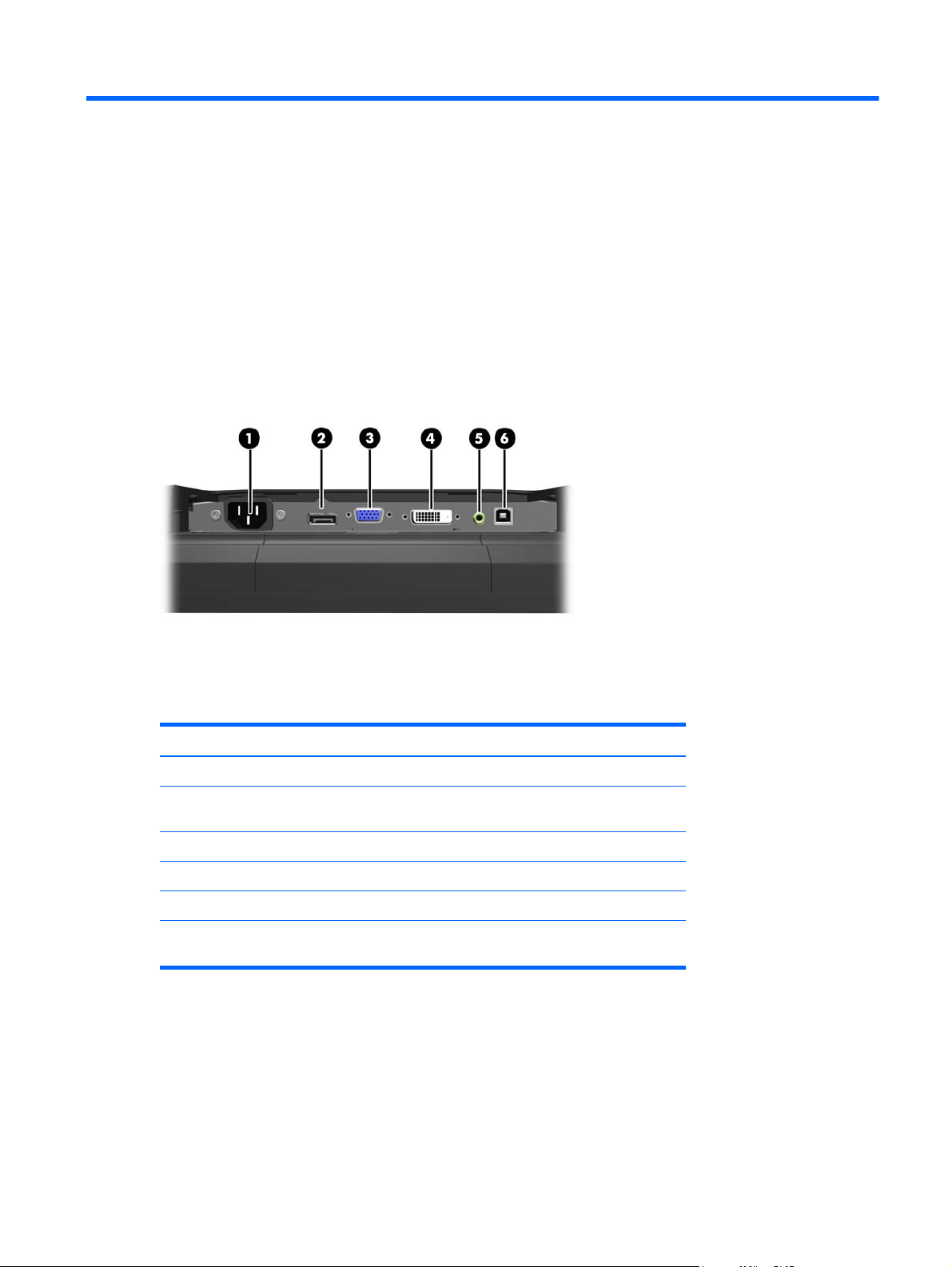
Identifying Rear Connectors
Figure 2-1 Rear Connectors
Table 2-1 Rear Connectors
Connector Function
1 AC Power Connects the AC power cord to the monitor.
2 DisplayPort Connects a DisplayPort video cable from the PC to the
3 VGA Connects a VGA video cable from the PC to the monitor.
4 DVI Connects a DVI video cable from the PC to the monitor.
5 Audio In Connects an audio cable from the PC to the monitor.
6 USB Upstream Connects a USB cable from the PC to the monitor (required
monitor.
for optional USB modules and touch screen operation).
Identifying Rear Connectors 3
Page 10

Installing Optional USB Modules
There are three optional USB modules available from HP (sold separately):
(1) a webcam for live video functions
●
(2) a retail integrated fingerprint reader to add security identification functions
●
(3) a retail integrated dual-head magnetic stripe reader for card data read
●
Figure 2-2 Optional USB Modules
The USB modules can be installed on the top of the monitor, the bottom of the monitor, or on either
side of the monitor.
NOTE: If you are installing a webcam, HP recommends that you install it on top of the monitor for
proper video orientation.
Figure 2-3 USB Module Installation Locations
NOTE: These USB ports only support the USB modules listed above. They do not support optical
drives or hard drives.
The procedure for installing a USB module is the same for all modules. To install a USB module:
1. Place the monitor panel face down on a flat surface covered with a clean, dry cloth.
4 Chapter 2 Setting Up the Monitor
Page 11
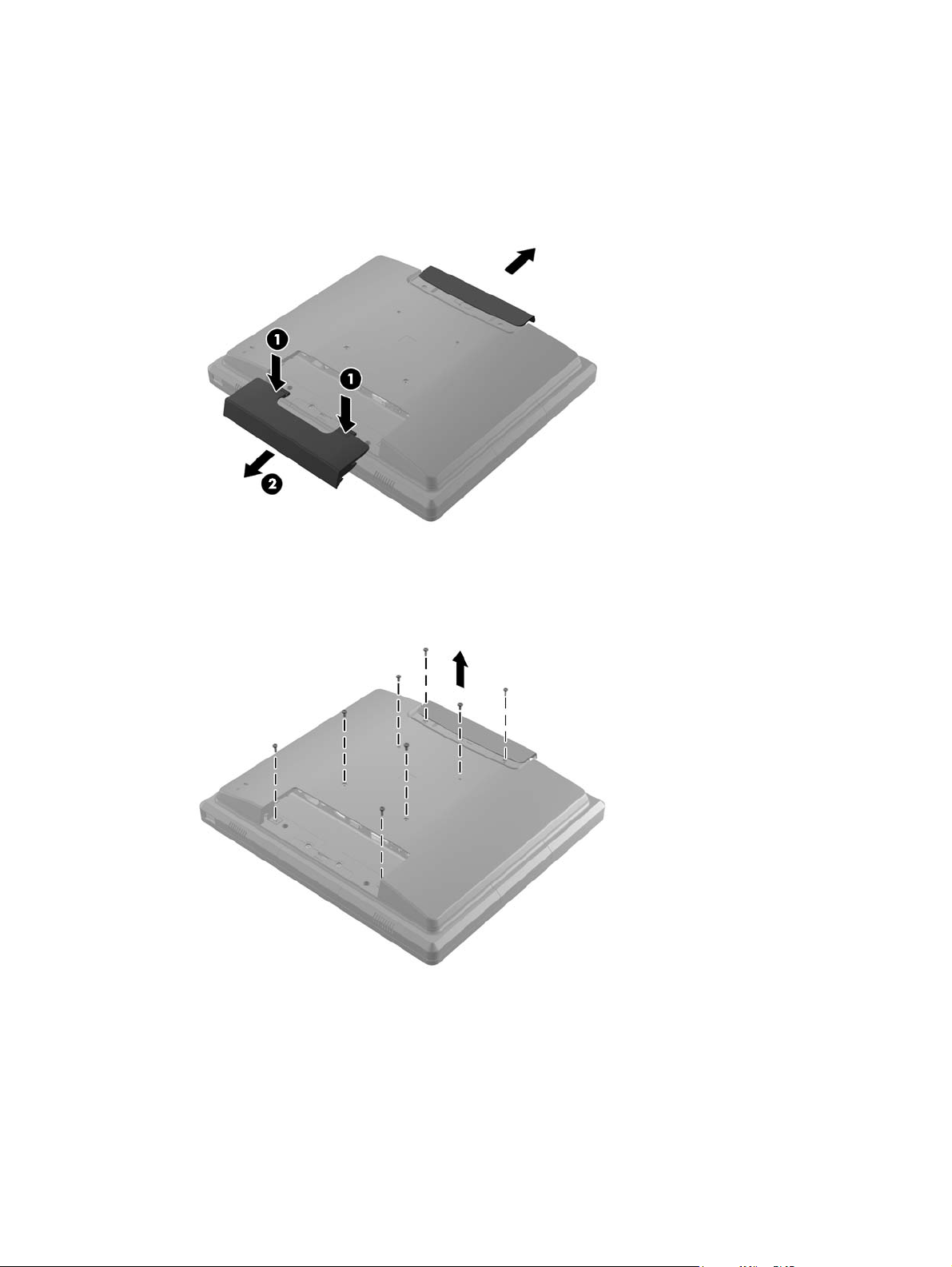
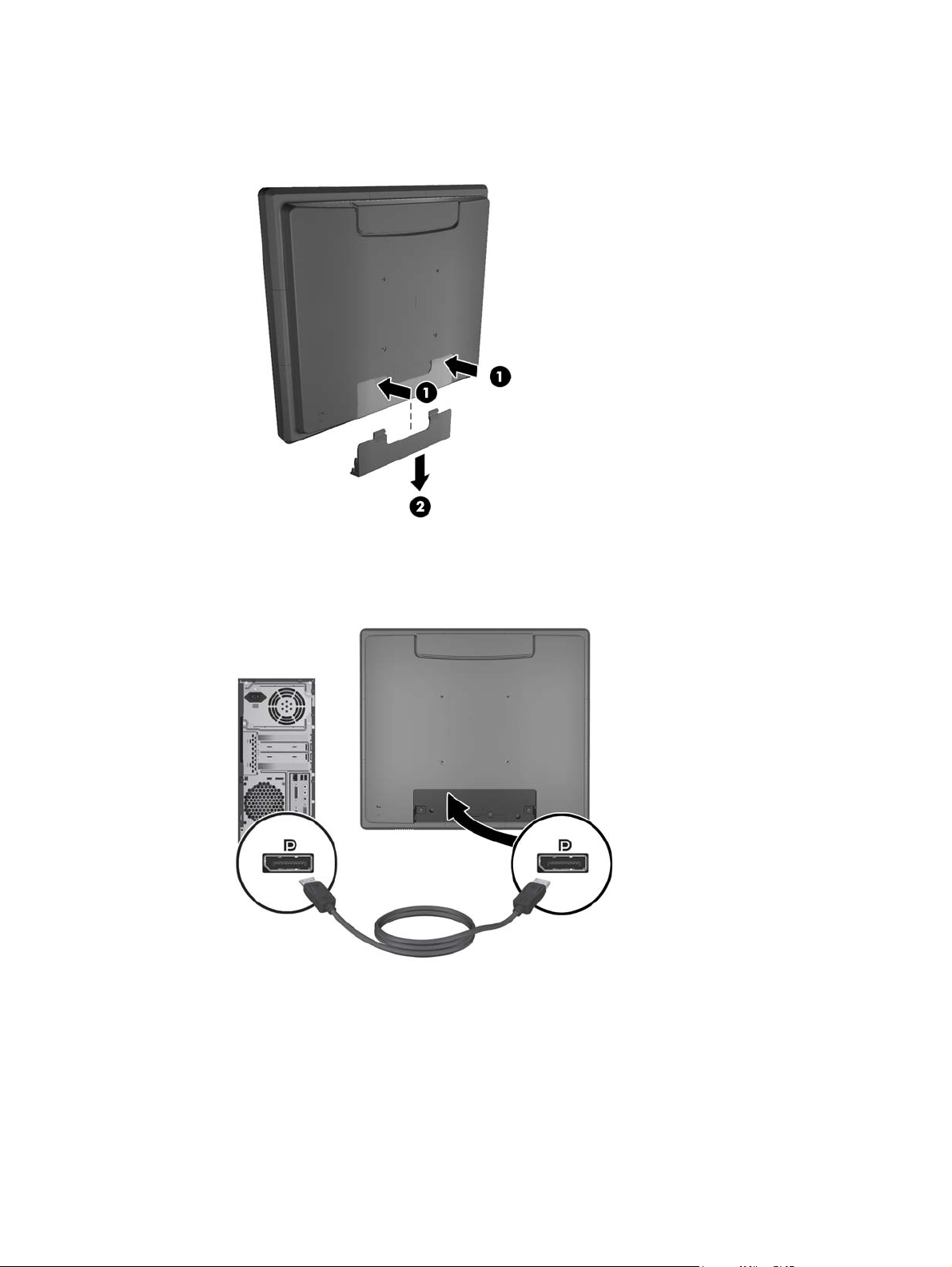
2. Slide the top cover plate on the back of the monitor up approximately 12mm (1/2 inch) to access
two of the rear panel screws. Remove the cable connection cover plate by pressing the two
ribbed areas at the top of the cover (1) and pulling the cover straight down and off the monitor
(2) to access two more of the rear panel screws.
Figure 2-4 Removing the Top and Bottom Cover Plates
3. Remove the eight screws that attach the rear panel to the monitor.
Figure 2-5 Removing the Rear Panel Screws
Installing Optional USB Modules 5
Page 12
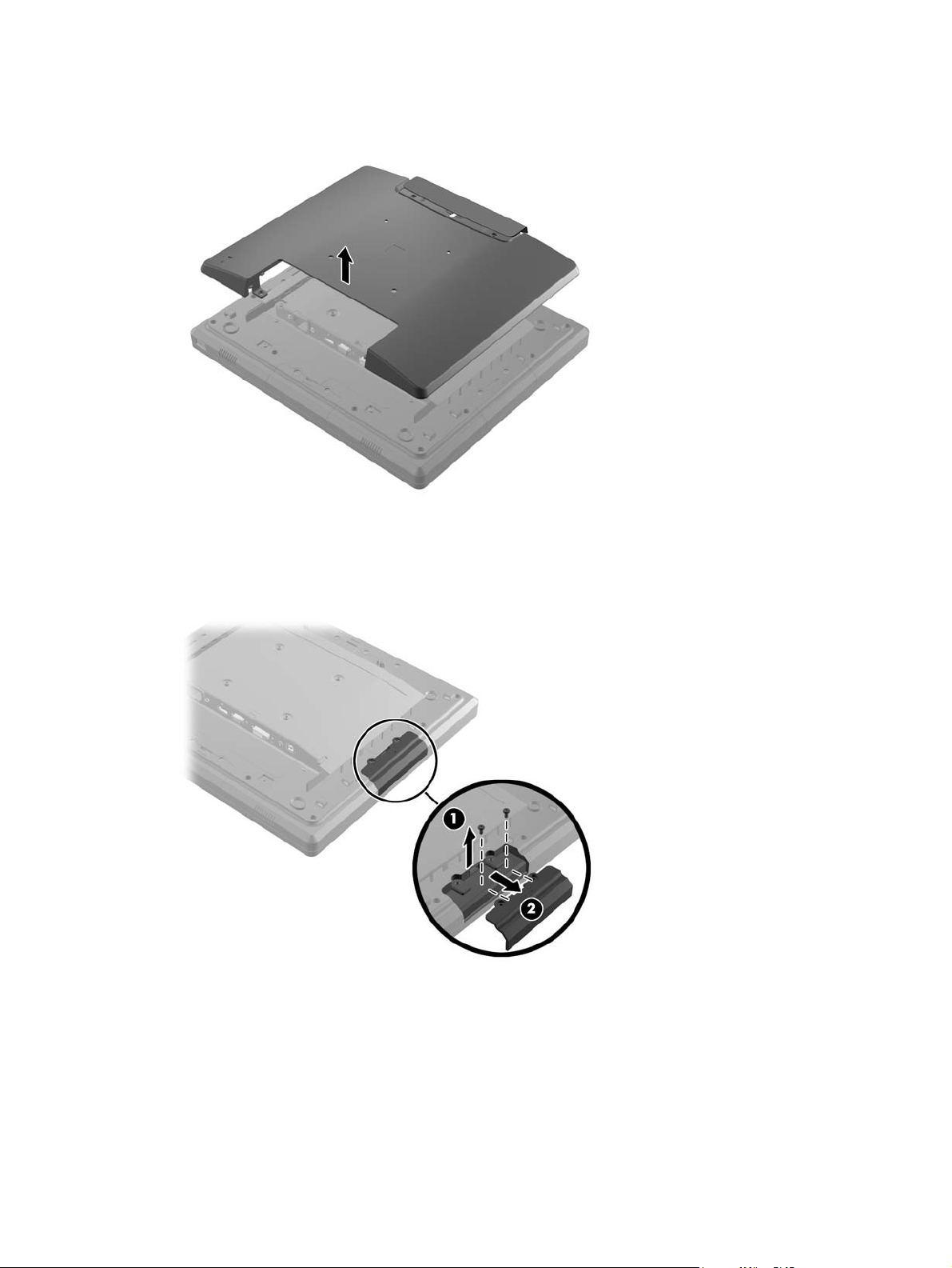
4. Lift the rear panel up and off the monitor.
Figure 2-6 Removing the Rear Panel
5. Remove the two screws that attach the USB cover plate to the monitor (1) then slide the cover
plate off the monitor (2). Remove only the cover plate that is in the location where you want to
install the USB module.
Figure 2-7 Removing the USB Cover Plate
6 Chapter 2 Setting Up the Monitor
Page 13
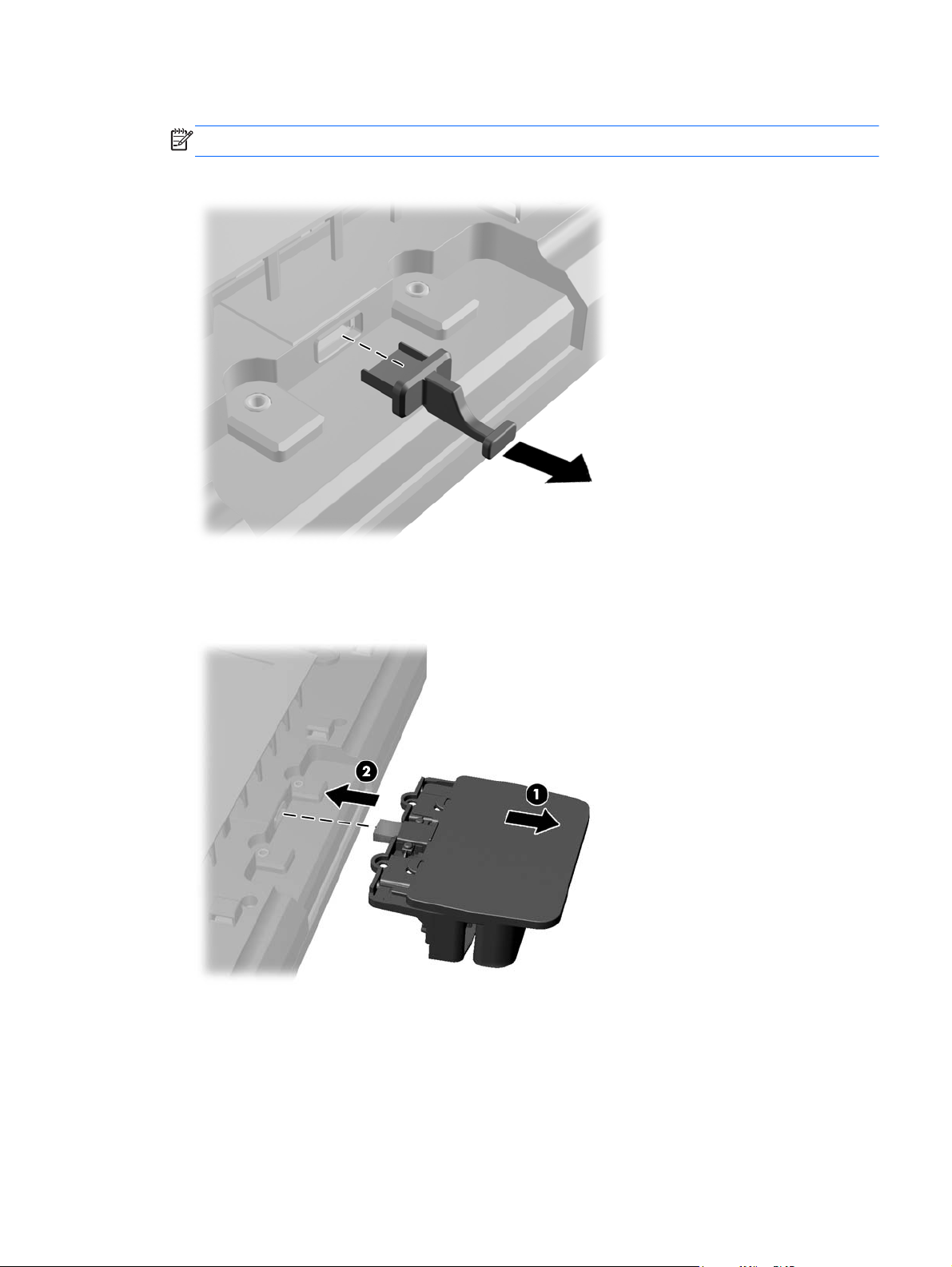
6. Pull the plug that is inserted in the USB port out of the port.
NOTE: Some models do not have plugs in the USB ports.
Figure 2-8 Removing the USB Plug
7. Slide the module screw hole cover plate back (1) and insert the USB connector on the module
into the USB port (2).
Figure 2-9 Inserting the USB Module
Installing Optional USB Modules 7
Page 14

8. Install the two screws that were previously removed (1) and slide the cover plate on the module
forward to cover the screws (2).
Figure 2-10 Securing the USB Module
9. Replace the rear panel and insert the eight screws that attach the panel to the monitor.
Figure 2-11 Replacing the Rear Panel
8 Chapter 2 Setting Up the Monitor
Page 15

10. Slide the top cover plate down and replace the cable connection cover plate.
Figure 2-12 Replacing the Top and Bottom Cover Plates
11. Ensure that the USB upstream cable is connected between the monitor and the PC.
12. Install the applicable software and drivers for the module(s) according to instructions provided
with the accessory.
Attaching an Optional Monitor Stand
The optional monitor stand is available from HP (sold separately). The stand attaches to the 100mm
VESA mounting holes on the rear panel.
1. Place the monitor panel face down on a flat surface covered with a clean, dry cloth.
2. If there are screws installed in the VESA mounting holes on the rear panel, remove the screws.
Attaching an Optional Monitor Stand 9
Page 16

3. Install the two large screws included with the stand into the two lower VESA mounting holes on
the monitor.
Figure 2-13 Installing the Lower Mounting Screws
4. Place the stand mounting bracket on the rear of monitor so that the keyholes on the bracket
align with the two large screws on the monitor then slide the mounting bracket toward the top of
the monitor so that the screws heads are captured inside the keyholes.
Figure 2-14 Aligning the Mounting Bracket
10 Chapter 2 Setting Up the Monitor
Page 17

5. Install the two small screws included with the stand into the upper two VESA mounting holes to
secure the mounting bracket to the stand.
Figure 2-15 Installing the Upper Mounting Screws
Routing Cables through the Optional Monitor Stand
The optional stand has a clip on the neck of the stand and a hole on the base of the stand for routing
cables.
1. Remove the clip on the neck of the stand by pressing inward on one side of the clip (1) and
pulling outward on the other side of the clip (2).
Figure 2-16 Removing the Cable Routing Clip
Attaching an Optional Monitor Stand 11
Page 18

2. Replace the clip on the neck of the stand so that it secures the cables.
Figure 2-17 Replacing the Cable Routing Clip
3. Route the cables through the hole in the center of the base.
Figure 2-18 Routing Cables through the Base
12 Chapter 2 Setting Up the Monitor
Page 19

Adjusting the Optional Monitor Stand
You can adjust the monitor stand height and tilt to a variety of positions. Choose a position that is the
most ergonomically appropriate for your usage.
NOTE: Tilt range is -5 degrees forward to +60 degrees backward.
Figure 2-19 Adjusting the Optional Monitor Stand
Mounting the Monitor
The monitor panel can be attached to a wall, swing arm, or other mounting fixture.
NOTE: This apparatus is intended to be supported by UL or CSA Listed wall mount bracket.
1. Remove the four screws from the VESA mounting holes on the back of the monitor.
CAUTION: This monitor supports the VESA industry standard 100 mm mounting holes. To
attach a third-party mounting solution to the monitor, four 4 mm, 0.7 pitch, and 10 mm long
screws are required. Longer screws must not be used because they may damage the monitor. It
is important to verify that the manufacturer’s mounting solution is compliant with the VESA
standard and is rated to support the weight of the monitor display panel. For best performance, it
is important to use the power and video cables provided with the monitor.
2. To attach the monitor to a mounting fixture, insert the four screws that were previously removed
through the holes on the mounting fixture and into the mounting holes on the monitor. Follow the
manufacturer’s documentation provided with the mounting fixture for additional assembly
instructions.
3. Connect the required cables to the monitor panel and PC.
Connecting the Cables
NOTE: If the monitor is attached to the optional stand, route the cables through the stand as
described in
Routing Cables through the Optional Monitor Stand on page 11.
1. Place the monitor in a convenient, well-ventilated location near the computer.
Mounting the Monitor 13
Page 20
2. Remove the cable connection cover on the rear of the monitor by pressing the two ribbed areas
at the top of the cover (1) and pulling the cover straight down and off the monitor (2).
Figure 2-20 Removing the Cable Connection Cover Plate
3. Depending on your configuration, connect either the DisplayPort, DVI, or VGA video cable
between the PC and the monitor.
Figure 2-21 Connecting the DisplayPort Video Cable
●
14 Chapter 2 Setting Up the Monitor
Page 21

Figure 2-22 Connecting the DVI Video Cable
●
● Figure 2-23 Connecting the VGA Video Cable
Connecting the Cables 15
Page 22
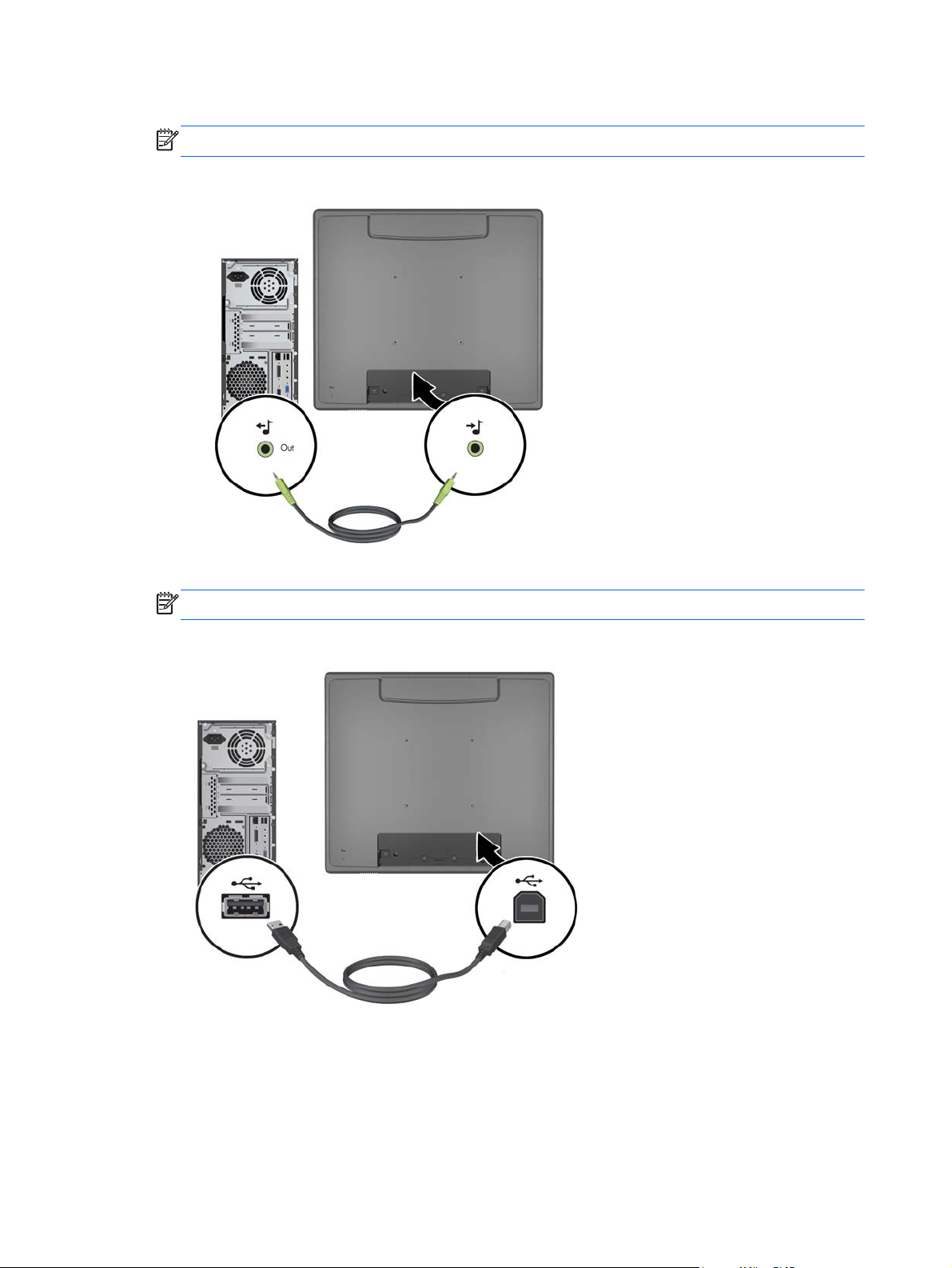
4. Connect the audio cable between the PC audio out port and the monitor audio in port.
NOTE: The audio cable is required for the monitor speakers to function.
Figure 2-24 Connecting the Audio Cable
5. Connect the USB upstream cable between the PC and the monitor.
NOTE: The USB cable is required for optional USB modules and touch screen operation.
Figure 2-25 Connecting the USB Cable
16 Chapter 2 Setting Up the Monitor
Page 23

6. Connect the AC power cord between the monitor and an electrical wall outlet.
Figure 2-26 Connecting the AC Power Cord
WARNING! To reduce the risk of electric shock or damage to the equipment:
Do not disable the power cord grounding plug. The grounding plug is an important safety
feature.
Plug the power cord into a grounded (earthed) electrical outlet that is easily accessible at all
times.
Disconnect power from the equipment by unplugging the power cord from the electrical outlet.
For your safety, do not place anything on power cords or cables. Arrange them so that no one
may accidentally step on or trip over them. Do not pull on a cord or cable. When unplugging from
the electrical outlet, grasp the cord by the plug.
7. Replace the cable connection cover on the rear of the monitor.
Figure 2-27 Replacing the Cable Connection Cover Plate
Connecting the Cables 17
Page 24
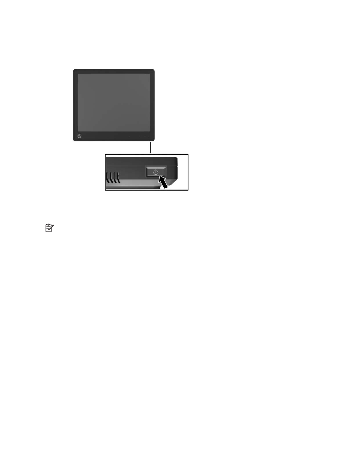
8. Turn on the computer, then press the power button on the underside of the monitor to power it
on.
Figure 2-28 Pressing the Power Button
Installing the Touch Drivers for Microsoft Windows XP
NOTE: You do not need to install the touch driver software for Microsoft Windows 7 or Windows
Vista. Microsoft plug-and-play touch drivers are already included in those operating systems for this
monitor.
Using the touch screen function on systems running Microsoft Windows XP requires the HP touch
driver installation. The touch driver software can be downloaded from the Internet or from the HP
software and documentation CD included with the monitor.
Installing Drivers from the CD
1. Insert the HP software and documentation CD in the computer’s optical drive. The CD menu is
displayed.
2. Select the menu to install the touch driver for Microsoft Windows XP from the CD menu.
3. Follow the on screen instructions to complete the touch driver installation process.
Downloading Drivers from the Internet
1. Go to http://www.hp.com/support.
2. Select your country or region.
3. Select your language.
4. Select Drivers & Software and enter your monitor model name and number.
5. Follow the instructions on the screen to download the touch driver software.
18 Chapter 2 Setting Up the Monitor
Page 25
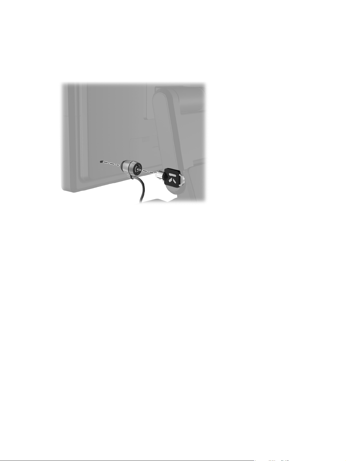
Installing a Cable Lock
When the monitor is assembled to the optional stand and used on a desktop, you can secure the
monitor to a fixed object with an optional cable lock available from HP.
Figure 2-29 Installing a Cable Lock
Locating the Rating Labels
The rating labels on the monitor provide the spare part number, product number, and serial number.
You may need these numbers when contacting HP about the monitor model. The rating labels are
located on the rear panel of the monitor display head.
Installing a Cable Lock 19
Page 26

3 Operating the Monitor
Front Panel Controls
Figure 3-1 Monitor Front Panel Controls
NOTE: The front panel controls are inactive unless they are illuminated. To activate the controls, tap
on the area where the icons are located. All icons will become illuminated and active. The backlight
for the icons will turn off upon exit from the OSD or when the OSD times out.
Table 3-1 Monitor Front Panel Controls
Control Function
1
2
3
Menu Opens the On-Screen Display (OSD) main menu.
– (Minus) If the OSD menu is on, tap to navigate backward through the OSD menu
and decrease adjustment levels.
If the OSD menu is inactive and the icons are illuminated, tap to open the
OSD volume control menu and adjust the volume level.
+ (Plus) If the OSD menu is on, tap to navigate forward through the OSD menu
and increase adjustment levels.
If the OSD menu is inactive and the icons are illuminated, tap to activate
the Source button that chooses the video signal input.
20 Chapter 3 Operating the Monitor
Page 27

Table 3-1 Monitor Front Panel Controls (continued)
Control Function
4
5
OK If the OSD menu is on, tap to select a menu item.
If the OSD menu is inactive and the icons are illuminated, tap to activate
the auto adjustment feature to optimize the screen image.
Power LED Green = Fully powered.
Amber = Sleep mode.
Flashing Amber = Sleep Timer mode.
Off = Power is off or the LED has been suppressed in the OSD
NOTE: To view an OSD menu simulator, visit the HP Customer Self Repair Services Media Library
http://www.hp.com/go/sml.
at
Power Management System
The monitor is equipped with the power management function which automatically reduces the power
consumption when not in use.
Table 3-2 Power Management
Mode Power Consumption
Full Power 44 W
Typical Power 26 W
Sleep 1 W
Off 0.5 W
It is recommended that you switch the monitor off when it is not in use for a long period of time.
NOTE: The monitor automatically goes through the power management system steps when it is
idle. To release the monitor from the power management system, press any key on the keyboard or
move the mouse or touch the touch screen. In order for the touch screen to bring the monitor from the
power management system, the touch screen function must be fully operational.
OSD Lock/Unlock
The OSD feature can be locked and unlocked. The monitor is shipped with the OSD menu in the
unlocked position.
To lock the OSD menu and disable the OSD controls, tap on the area where the OSD icons are
located so that the icons become illuminated and active, then press the Menu icon for 10 seconds. To
unlock the OSD menu and enable the OSD controls, press the Menu icon again for 10 seconds.
Power Button Lock/Unlock
The power button can be locked and unlocked. The monitor is shipped with the power button in the
unlocked position.
Power Management System 21
Page 28

To lock the power button, press the power button for 10 seconds. To unlock the power button, press
the power button again for 10 seconds. Unlocking the power button will power off the monitor. To
power it back on, press the power button.
Touch Screen Tips
The HP L6015tm and L6017tm retail displays use projected capacitive technology with an all glass
front surface and provides multi-touch functionality. The fast response rate enables the creation of
touch applications as well as supports speed sensitive applications.
Keep your display and touch sensor clean. The touch sensor requires very little maintenance. HP
recommends that you periodically clean the glass touch sensor surface. Be sure to turn off your
display before cleaning. Typically, an isopropyl alcohol and water solution ratio of 50:50 is the best
cleaning agent for your touch sensor. It is important to avoid using any caustic chemicals on the touch
sensor. Do not use any vinegar-based solutions.
Apply the cleaner with a soft, lint-free cloth. Avoid using gritty cloths. Always dampen the cloth and
then clean the sensor. Be sure to spray the cleaning liquid onto the cloth, not the sensor, so that drips
do not seep inside the display or stain the bezel.
Touch Screen Calibration
The retail touch monitor has been calibrated at the factory prior to shipment and should not need to
be calibrated when first installed. You should be able to accurately touch icons on the sensor.
However, if you find that the touch point is not registering on the screen where the stylus or finger
touches, the touch sensor’s active area may not be aligned to the underlying video and you will have
to perform the touch module calibration process.
Calibration for Windows Vista and Windows 7
To calibrate the touch module in Windows Vista and Windows 7:
1. After you connect your touch display, go to the Control Panel and click on Tablet PC Settings.
2. In the Tablet PC Settings dialog box, click on the Calibrate button and follow the instructions to
press the target marks on the touch screen. At the end of the calibration process, the touch
module should be aligned with the video and the touch points will be accurate.
Calibration for Windows XP
You must load the touch screen driver provided on the software and documentation CD that shipped
with the monitor if you are using Windows XP or a Windows XP based operating system (see
Installing the Touch Drivers for Microsoft Windows XP on page 18 for details). A Calibration Tool for
Windows XP is also included on the CD shipped with the monitor.
To calibrate the touch module in Windows XP:
1. Install the Calibration Tool from the software and documentation CD.
2. After installation, launch the Calibration Tool and follow the on screen instructions. At the end
of the calibration process, the touch module should be aligned with the video and the touch
points will be accurate.
22 Chapter 3 Operating the Monitor
Page 29

4 Finding More Information
Reference Guides
Refer to the HP LCD Monitors Reference Guide included on the CD shipped with the monitor and
available at
● Optimizing monitor performance
Safety and maintenance guidelines
●
Agency regulatory and environmental notices
●
● Using the OSD menu
Product Support
For additional information on using and adjusting your monitor, go to http://www.hp.com/support.
Select your country or region, select Product Support & Troubleshooting, and then enter your
monitor model in the SEARCH window.
NOTE: The monitor user guide, reference guide, and drivers are available at http://www.hp.com/
support.
http://www.hp.com/support for additional information on:
If the information provided in the guide or in the HP LCD Monitors Reference Guide do not address
your questions, you can contact support. For U.S. support, go to
For worldwide support, go to
Here you can:
Chat online with an HP technician
●
NOTE: When support chat is not available in a particular language, it is available in English.
E-mail support
●
Find support telephone numbers
●
Locate an HP service center
●
http://welcome.hp.com/country/us/en/wwcontact_us.html.
http://www.hp.com/go/contactHP.
Reference Guides 23
Page 30

A Troubleshooting
Touch Screen Troubleshooting
The following table lists possible problems and the recommended solutions.
Table A-1 Troubleshooting
Problem Solution
Computer does not recover from Sleep mode when the touch
screen is touched.
The USB cable is quickly removed from the monitor and
reinserted, and the touch function is lost.
Multi-touch gestures do not function on Windows 7 Home
Basic or Starter editions, Windows Vista, or Windows XP.
The Start, Close, and other icons are too small to touch with
a finger.
Touch operation does not function properly on lowerresolution video modes that are not displayed in fullscreen.
A single touch is recognized as two touches. If using a paint
tool, a single finger creates two lines.
When the monitor used is in a dual-screen configuration, the
touch function on the second display does not work.
Sleep mode recovery is not supported by the touch screen.
Use the keyboard or mouse to recover from Sleep mode.
Windows takes a minimum amount of time to adjust system
parameters when a USB device is either removed or
connected. Try removing the USB cable again, wait for at
least five seconds, and then plug it in again.
Only Windows 7 Home Premium, Professional, Enterprise,
and Ultimate editions support multi-touch gestures.
Windows 7 provides a large icon feature that supports touch
screen functions. This feature can be accessed in the
Control Panel. A stylus may also be used.
Although the monitor supports a fill-to-aspect ratio function,
the touch controller does not know how to respond to lessthan-fullscreen images. Either change the resolution to the
native resolution (1024 x 768 for the L6015tm model, 1280 x
1024 for the L6017tm model), or access the OSD menu and
select Image Control to enable Fill-to-Screen (default
setting).
The touch controller has a limitation on the size of the
"touch" area. A fingertip touch usually works better than a flat
forefinger or thumb touch.
The USB connection is only capable of operating a singletouch screen monitor. If the second monitor is a touch
monitor, you must connect a second USB cable.
24 Appendix A Troubleshooting
NOTE: Windows 7 Home Basic and Starter editions,
Windows Vista, and Windows XP do not support extended
display touch functionality. They support single-touch
functions on the primary monitor only, not the secondary
monitor (extended or cloned desktop).
Page 31

B Technical Specifications
NOTE: All performance specifications are provided by the component manufacturers. Performance
specifications represent the highest specification of all HP's component manufacturers' typical level
specifications for performance and actual performance may vary either higher or lower.
HP L6015tm Retail Touch Monitor
Table B-1 HP L6015tm Specifications
LCD Display
Type
Pixel Pitch 0.297 (H) x 0.297 (V) mm 0.01 (H) x 0.01 (V) in
Horizontal Frequency 24 to 83 kHz
Vertical Frequency 50 to 76 Hz
Maximum Resolution 1024 x 768 at 60Hz
Aspect Ratio 4:3
Contrast Ratio 700:1 (typical)
Brightness 350 nits
Response Time 8 ms
Color Gamut 68%
Viewing Angle (V/H at CR>10) 140 / 160
Video Sources VGA + DVI + DP
Front Controls Menu, Minus, Plus, OK, Power
OSD Main Menu Brightness, Contrast, Color, Image
38.1 cm
TFT LCD
Control, OSD Control, Management,
Language, Information, Factory Reset,
Source Control, Exit
15 inches
Touch Panel Projected Capacitive
Power Input AC 100-240V, 50-60Hz
Operating Conditions
Temperature (Operating)
Temperature (Storage)
Humidity
Altitude
5°C to 40°C (41°F to 104°F)
-20°C to 60°C (-4°F to 140°F)
20% ~ 80% (No Condensation)
0 to 5000 meters (16,400 feet)
HP L6015tm Retail Touch Monitor 25
Page 32

Table B-1 HP L6015tm Specifications (continued)
Dimensions
Width
Height (with stand)
Height (without stand)
Depth (with stand)
Depth (without stand)
Weight
Actual (unpacked, with stand)
Actual (unpacked, without stand)
Shipping (packaged without stand)
366.0 mm
414.0 mm
313.0 mm
283.4 mm
58.0 mm
6.8 kg
4.0 kg
5.9 kg
HP L6017tm Retail Touch Monitor
Table B-2 HP L6017tm Specifications
14.41 in
16.30 in
12.32 in
11.16 in
2.28 in
14.99 lb
8.82 lb
12.76 lb
LCD Display
Type
Pixel Pitch 0.264 (H) x 0.264 (V) mm 0.01 (H) x 0.01 (V) in
Horizontal Frequency 24 to 83 kHz
Vertical Frequency 50 to 76 Hz
Maximum Resolution 1280 x 1024 at 60Hz
Aspect Ratio 5:4
Contrast Ratio 1000:1 (typical)
Brightness 225 nits
Response Time 5 ms
Color Gamut 68%
Viewing Angle (V/H at CR>10) 160 / 170
Video Sources VGA + DVI + DP
Front Controls Menu, Minus, Plus, OK, Power
OSD Main Menu Brightness, Contrast, Color, Image
43.2 cm
TFT LCD
Control, OSD Control, Management,
Language, Information, Factory Reset,
Source Control, Exit
17 inches
Touch Panel Projected Capacitive
Power Input AC 100-240V, 50-60Hz
26 Appendix B Technical Specifications
Page 33

Table B-2 HP L6017tm Specifications (continued)
Operating Conditions
Temperature (Operating)
Temperature (Storage)
Humidity
Altitude
Dimensions
Width
Height (with stand)
Height (without stand)
Depth (with stand)
Depth (without stand)
Weight
Actual (unpacked, with stand)
Actual (unpacked, without stand)
Shipping (packaged without stand)
5°C to 40°C (41°F to 104°F)
-20°C to 60°C (-4°F to 140°F)
20% ~ 80% (No Condensation)
0 to 5000 meters (16,400 feet)
385.58 mm
423.31 mm
338.90 mm
283.39 mm
58.00 mm
7.5 kg
4.7 kg
6.5 kg
Projected Capacitive Technology
15.18 in
16.67 in
13.34 in
11.16 in
2.28 in
16.53 lb
10.36 lb
14.33 lb
Table B-3 Projected Capacitive Specifications
Input Method Bare finger, 3 layers of food service gloves, 3M SmartPen stylus
Positional Accuracy Standard deviation of error is less than 0.080 in (2.03 mm). Equates to less than ±1% error
on most displays.
Resolution Accuracy More than 100,000 touchpoints/in² (15,500 touchpoints/cm²) for a 15-inch touch screen.
The controller firmware program may reduce resolution to accommodate axis length
greater than 465 mm.
Touch Activation Force Typically less than 3 ounces (85 grams).
Surface Durability Surface scratches will not cause functional failures regardless of the length or depth of the
scratch. A Mohs’ pick with a hardness rating of 6 or higher is required to induce a cosmetic
scratch.
Expected Life Performance No known wear-out mechanism, as there are no layers, coatings, or moving parts.
Optical Light Transmission
(per ASTM D1003)
Electrostatic Protection (per
EN 61 000-4-2, 1995)
Technology has been operationally tested to more than 50 million touches in one location
without failure, using a stylus similar to a finger.
>87%
Meets Level 4 (15 kV air/8j V contact discharges).
Projected Capacitive Technology 27
Page 34

Recognizing Preset Display Resolutions
The display resolutions listed below are the most commonly used modes and are set as factory
defaults. This monitor automatically recognized these preset modes and they will appear properly
sized and centered on the screen.
L6015tm and L6017tm
Table B-4 Factory Preset Modes
Preset Pixel Format Horz Freq (kHz) Vert Freq (Hz)
1 640 × 480 31.469 59.940
2 720 × 400 31.469 70.087
3 800 × 600 37.879 60.317
4 1024 × 768 48.363 60.004
5 1280 × 1024
(L6017tm only)
63.981 60.020
Entering User Modes
The video controller signal may occasionally call for a mode that is not preset if:
You are not using a standard graphics adapter.
●
You are not using a preset mode.
●
If this occurs, you may need to readjust the parameters of the monitor screen by using the on-screen
display. Your changes can be made to any or all of these modes and saved in memory. The monitor
automatically stores the new setting, then recognizes the new mode just as it does a preset mode. In
addition to the 4 or 5 factory preset, there are 10 user modes that can be entered and stored.
The only condition to store as a user mode is the new display information must have 1 KHz difference
for horizontal frequency or 1 Hz for vertical frequency or the sync signal polarities are different from
the default modes.
Energy Saver Feature
When the monitor is in its normal operating mode, the monitor uses less than 21 watts and the Power
light is green.
The monitor also supports a reduced power state. The reduced power state will be entered into if the
monitor detects the absence of either the horizontal sync signal and/or the vertical sync signal. Upon
detecting the absence of these signals, the monitor screen is blanked, the backlight is turned off, and
the power light is turned amber. When the monitor is in the reduced power state, the monitor will
utilize less than 1 watt of power. There is a brief warm up period before the monitor will return to its
normal operating mode.
Refer to the computer manual for instructions on setting energy saver features (sometimes called
power management features).
NOTE: The above power saver feature only works when connected to computers that have energy
saver features.
28 Appendix B Technical Specifications
Page 35

By selecting the settings in the monitor's Energy Saver utility, you can also program the monitor to
enter into the reduced power state at a predetermined time. When the monitor's Energy Saver utility
causes the monitor to enter the reduced power state, the power light blinks amber.
Energy Saver Feature 29
 Loading...