

Page 1

HP L6010 Retail Monitor
User Guide
Page 2

© 2012 Hewlett-Packard Development
Company, L.P.
Microsoft, Windows, and Windows Vista are
either trademarks or registered trademarks
of Microsoft Corporation in the United
States and/or other countries.
The only warranties for HP products and
services are set forth in the express
warranty statements accompanying such
products and services . Nothing herein
should be construed as constituting an
additional warranty. HP shall not be liable
for technical or editorial errors or omissions
contained herein.
This document contains proprietary
information that is protected by copyright.
No part of this document may be
photocopied, reproduced, or translated to
another language without the prior written
consent of Hewlett-Packard Company.
First Edition (June 2012)
Document Part Number: 688916-001
Page 3

About This Guide
This guide provides information on monitor features, setting up the monitor, and technical
specifications.
WARNING! Text set off in this manner indicates that failure to follow directions could result in bodily
harm or loss of life.
CAUTION: Text set off in this manner indicates that failure to follow directions could result in
damage to equipment or loss of information.
NOTE: Text set off in this manner provides important supplemental information.
iii
Page 4

iv About This Guide
Page 5

Table of contents
1 Product Features ............................................................................................................................................ 1
HP L6010 Retail Monitor ...................................................................................................................... 1
Optional Accessories ............................................................................................................................ 1
2 Setting Up the Monitor ................................................................................................................................... 2
Identifying Rear Connectors ................................................................................................................. 2
Attaching an Optional Monitor Stand .................................................................................................... 2
Attaching the Optional Monitor Stand in the Low-Mount Position ........................................ 3
Attaching the Optional Monitor Stand in the High-Mount Position ....................................... 7
Adjusting the Optional Monitor Stand ................................................................................ 12
Mounting the Monitor .......................................................................................................................... 12
Connecting the Cables ....................................................................................................................... 12
Installing a Cable Lock ....................................................................................................................... 18
Locating the Rating Labels ................................................................................................................. 18
3 Operating the Monitor .................................................................................................................................. 19
Front Panel Controls .......................................................................................................................... 19
Power Management System .............................................................................................................. 20
OSD Lock/Unlock ............................................................................................................................... 20
Power Button Lock/Unlock ................................................................................................................. 20
4 Locating Additional Information .................................................................................................................. 22
5 Technical Specifications .............................................................................................................................. 23
HP L6010 Retail Monitor .................................................................................................................... 23
Recognizing Preset Display Resolutions ............................................................................................ 25
HP L6010 Retail Monitor .................................................................................................... 25
Entering User Modes .......................................................................................................................... 25
Energy Saver Feature ........................................................................................................................ 26
v
Page 6

vi
Page 7

1 Product Features
HP L6010 Retail Monitor
The LCD (liquid crystal display) monitor has an active matrix, thin-film transistor (TFT) panel. The
monitor features include:
● 26.4 cm (10.4-inch) diagonal viewable area display with 1024 x 768 resolution, plus full support
for lower resolutions, includes custom scaling for maximum image size while preserving original
aspect ratio
Industrial LCD panel with WLED backlight that provides better clarity and consumes less energy
●
USB 2.0 hub with one external USB port
●
75mm VESA mounting support
●
Video input supports VGA analog signal input plus DisplayPort and DVI digital signal inputs
●
Audio In port and built-in 1-watt speakers
●
Security provision to enable locking the monitor to a fixed object
●
Plug and play capability if supported by the system
●
● High-Bandwidth Digital Content Protection (HDCP) copy protection on DVI and DisplayPort
inputs
On-Screen Display (OSD) adjustments in several languages for easy setup and screen
●
optimization
Software and documentation CD that includes driver software and product documentation
●
Energy Star® qualified (for additional certifications and regulatory notices, refer to the HP LCD
●
Monitors Reference Guide provided on the CD included with this product):
Optional Accessories
The following can be purchased separately from HP:
● Dual position adjustable stand
Cable lock
●
HP L6010 Retail Monitor 1
Page 8
2 Setting Up the Monitor
To set up the monitor, ensure that the power is turned off to the monitor, computer system, and other
attached devices, then follow the instructions below.
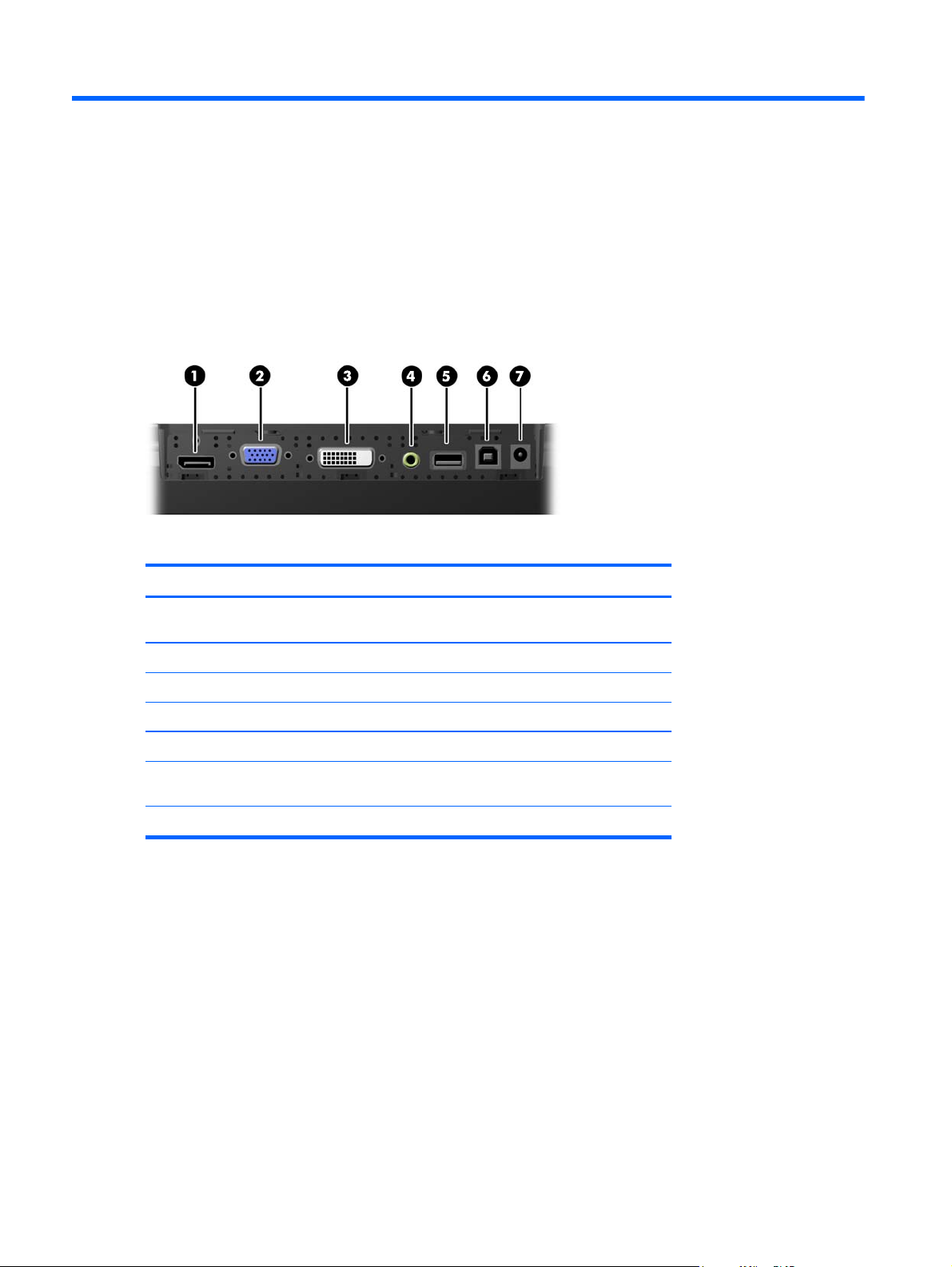
Identifying Rear Connectors
Figure 2-1 Rear Connectors
Table 2-1 Rear Connectors
Connector Function
1 DisplayPort Connects a DisplayPort video cable from the PC to the
monitor.
2 VGA Connects a VGA video cable from the PC to the monitor.
3 DVI Connects a DVI video cable from the PC to the monitor.
4 Audio In Connects an audio cable from the PC to the monitor.
5 USB Downstream Connects external USB devices to the monitor.
6 USB Upstream Connects a USB cable from the PC to the monitor (required
7 DC Power Connects the external power adapter to the monitor.
for USB downstream functionality).
Attaching an Optional Monitor Stand
The optional monitor stand is available from HP (sold separately). The stand attaches to the 75mm
VESA mounting holes on the rear panel.
2 Chapter 2 Setting Up the Monitor
Page 9
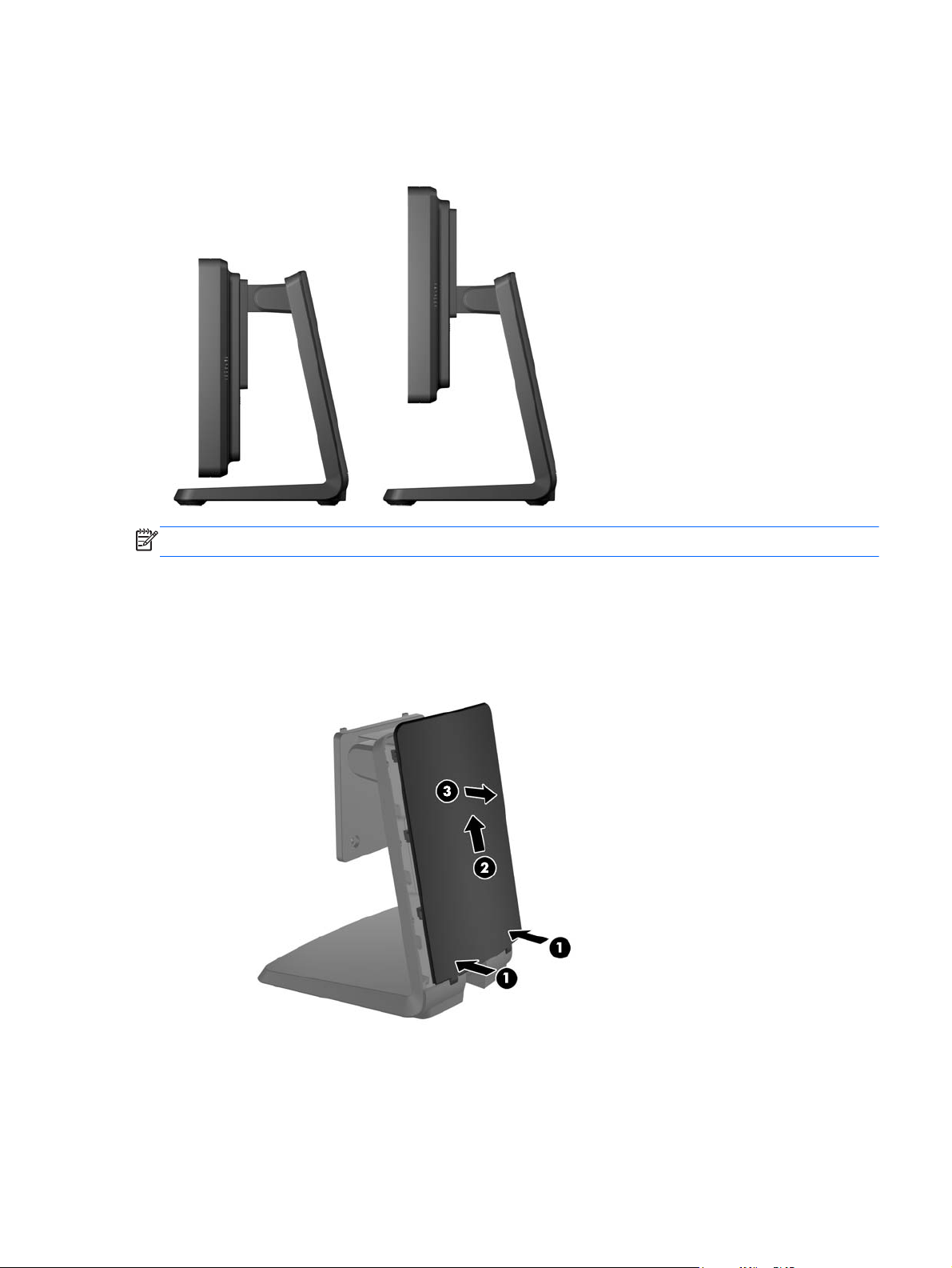
The monitor can be attached to the stand in a low-mount or high-mount position. Before attaching the
stand, decide which position is best for your configuration.
Figure 2-2 Monitor Stand Low-Mount and High-Mount Configurations
NOTE: The stand is shipped in the low-mount configuration.
Attaching the Optional Monitor Stand in the Low-Mount Position
1. Remove the stand's rear cover by pressing on the two pressure points near the bottom of the
cover (1), then sliding the cover up (2) and pulling it off the stand (3).
Figure 2-3 Removing the Rear Cover
Attaching an Optional Monitor Stand 3
Page 10
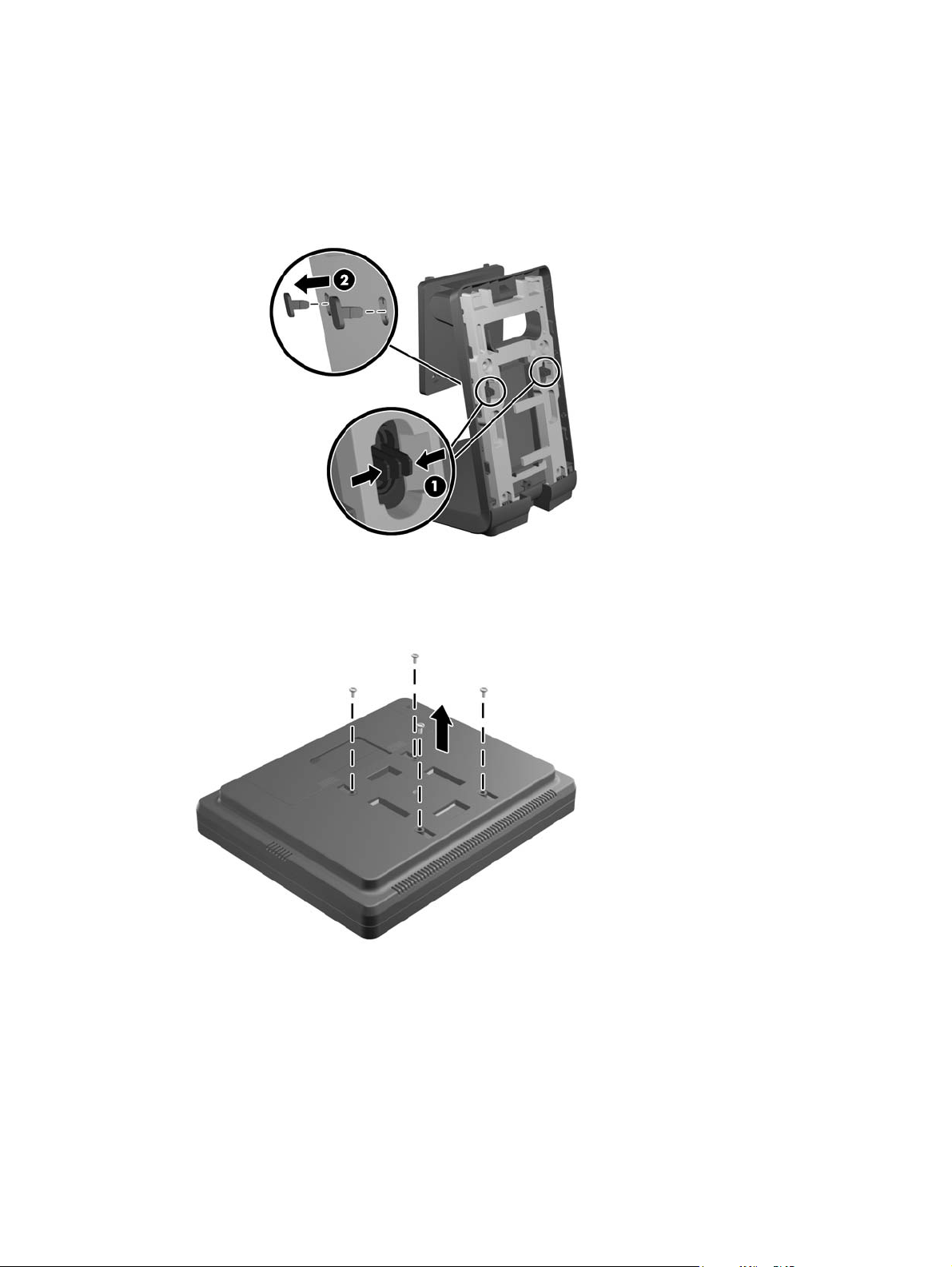
2. To allow access to the mounting screws, remove the two plugs in the center of the stand by
pinching together the tabs on the back of the plugs (1) then pulling the plugs out of the front of
the stand (2).
Figure 2-4 Removing the Access Plugs
3. Place the monitor face down on a flat surface covered with a clean, dry cloth and remove the
four Phillips mounting screws from the rear of the monitor.
Figure 2-5 Removing the Mounting Screws
4 Chapter 2 Setting Up the Monitor
Page 11

4. Insert the hooks on the stand mounting bracket into the slots on the rear of the monitor and slide
the stand toward the top of the monitor so that the hooks catch inside the slots.
Figure 2-6 Attaching the Stand
5. Install the two Phillips mounting screws that secure the mounting bracket to the monitor. Use a
Phillips screwdriver long enough to go through the access holes on the stand.
Figure 2-7 Securing the Stand
Attaching an Optional Monitor Stand 5
Page 12

6. With the monitor in the upright position, reinsert the access plugs in the stand.
Figure 2-8 Replacing the Access Plugs
7. Route the cables through the upper cable access hole at the top of the stand, behind the cable
security brackets, and out the cable access hole at the bottom of the stand.
NOTE: Refer to Connecting the Cables on page 12 for information on cable connections.
Figure 2-9 Routing the Cables
6 Chapter 2 Setting Up the Monitor
Page 13

8. Place the rear cover on the back of the stand with the top of the cover slightly above the top of
the stand then slide the cover down to lock it in place.
Figure 2-10 Replacing the Rear Cover
Attaching the Optional Monitor Stand in the High-Mount Position
1. Remove the four Phillips screws that attach the mounting bracket to the stand and remove the
bracket.
Figure 2-11 Removing the Mounting Bracket
Attaching an Optional Monitor Stand 7
Page 14

2. Rotate the mounting bracket 180°.
Figure 2-12 Rotating the Mounting Bracket 180°
3. Replace the four Phillips screws that attach the mounting bracket to the stand to secure the
bracket to the stand.
Figure 2-13 Attaching the Mounting Bracket
8 Chapter 2 Setting Up the Monitor
Page 15

4. Place the monitor face down on a flat surface covered with a clean, dry cloth and remove the
four Phillips mounting screws from the rear of the monitor.
Figure 2-14 Removing the Mounting Screws
5. Insert the hooks on the stand mounting bracket into the slots on the rear of the monitor and slide
the stand toward the bottom of the monitor so that the hooks catch inside the slots.
Figure 2-15 Attaching the Stand
Attaching an Optional Monitor Stand 9
Page 16

6. Install the two Phillips mounting screws that secure the mounting bracket to the monitor.
Figure 2-16 Securing the Mounting Bracket
7. Position the monitor and stand in the upright position, and then remove the stand rear cover by
pressing on the two pressure points near the bottom of the cover (1), then sliding the cover up
(2) and pulling it off the stand (3).
Figure 2-17 Removing the Rear Cover
10 Chapter 2 Setting Up the Monitor
Page 17

8. Route the cables through the upper cable access hole at the top of the stand, behind the cable
security brackets, and out the cable access hole at the bottom of the stand.
NOTE: Refer to Connecting the Cables on page 12 for information on cable connections.
Figure 2-18 Routing the Cables
9. Place the rear cover on the back of the stand so with the top of the cover slightly above the top
of the stand then slide the cover down to lock it in place.
Figure 2-19 Replacing the Rear Cover
Attaching an Optional Monitor Stand 11
Page 18

Adjusting the Optional Monitor Stand
For viewing clarity, adjust the monitor forward (up to -5 degrees) or backward (up to +35 degrees).
Figure 2-20 Adjusting the Tilt
Mounting the Monitor
The monitor panel can be attached to a wall, swing arm, or other mounting fixture.
NOTE: This apparatus is intended to be supported by UL or CSA Listed wall mount bracket.
1. Remove the four screws from the VESA mounting holes on the back of the monitor.
CAUTION: This monitor supports the VESA industry standard 75mm mounting holes. To
attach a third-party mounting solution to the monitor, four 4 mm, 0.7 pitch, and 10 mm long
screws are required. Longer screws must not be used because they may damage the monitor. It
is important to verify that the manufacturer’s mounting solution is compliant with the VESA
standard and is rated to support the weight of the monitor display panel. For best performance, it
is important to use the power and video cables provided with the monitor.
2. To attach the monitor to a mounting fixture, insert the four screws that were previously removed
through the holes on the mounting fixture and into the mounting screw holes on the monitor.
Follow the manufacturer’s documentation provided with the mounting fixture for additional
assembly instructions.
3. Connect the required cables to the monitor panel and PC.
Connecting the Cables
NOTE: If the monitor is attached to the optional stand, route the cables through the stand as
described in
the Optional Monitor Stand in the High-Mount Position on page 7.
1. Place the monitor in a convenient, well-ventilated location near the computer.
Attaching the Optional Monitor Stand in the Low-Mount Position on page 3 or Attaching
12 Chapter 2 Setting Up the Monitor
Page 19
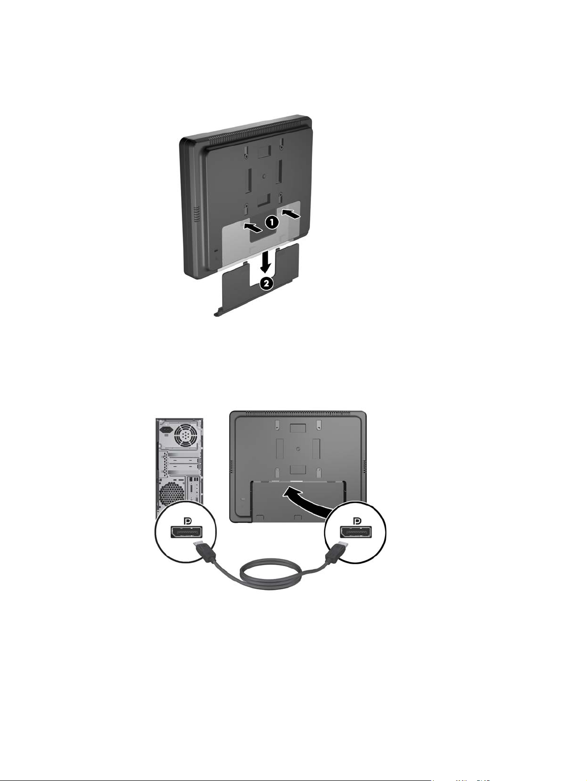
2. Remove the cable connection cover on the rear of the monitor by pressing the two ribbed areas
at the top of the cover (1) and pulling the cover straight down and off the monitor (2).
Figure 2-21 Removing the Cable Connection Cover Plate
3. Depending on your configuration, connect either the DisplayPort, DVI, or VGA video cable
between the PC and the monitor.
Figure 2-22 Connecting the DisplayPort Video Cable
●
Connecting the Cables 13
Page 20

Figure 2-23 Connecting the DVI Video Cable
●
● Figure 2-24 Connecting the VGA Video Cable
14 Chapter 2 Setting Up the Monitor
Page 21

4. Connect the audio cable between the PC audio out port and the monitor audio in port.
NOTE: The audio cable is required for the monitor speakers to function.
Figure 2-25 Connecting the Audio Cable
5. Connect the USB upstream cable between the PC and the monitor.
NOTE: The USB cable is required for the USB downstream port to function.
Figure 2-26 Connecting the USB Cable
Connecting the Cables 15
Page 22
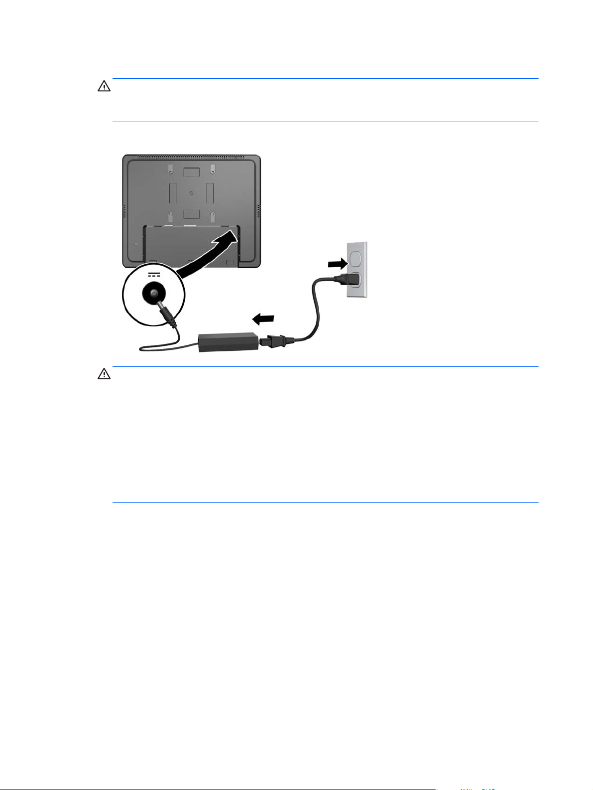
6. Connect the DC cable to the monitor and connect the AC power cord to an electrical wall outlet.
WARNING! For use only with the attached power adapter (output 12V DC) which has a
UL.CSA listed license (only for monitors with a power adapter).
Manufacturer: TPV ELECTRONICS(FUJIAN) CO., LTD model ADPC1236-
Figure 2-27 Connecting the Power Cord
WARNING! To reduce the risk of electric shock or damage to the equipment:
Do not disable the power cord grounding plug. The grounding plug is an important safety
feature.
Plug the power cord into a grounded (earthed) electrical outlet that is easily accessible at all
times.
Disconnect power from the equipment by unplugging the power cord from the electrical outlet.
For your safety, do not place anything on power cords or cables. Arrange them so that no one
may accidentally step on or trip over them. Do not pull on a cord or cable. When unplugging from
the electrical outlet, grasp the cord by the plug.
16 Chapter 2 Setting Up the Monitor
Page 23
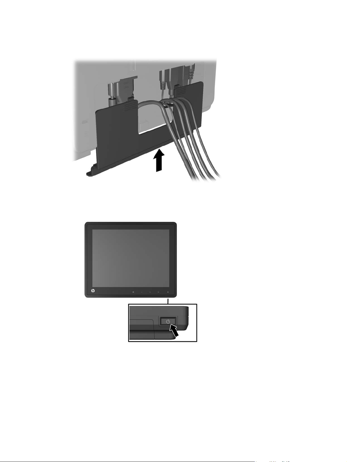
7. Replace the cable connection cover on the rear of the monitor.
Figure 2-28 Replacing the Cable Connection Cover Plate
8. Turn on the computer, then press the power button on the underside of the monitor to power it
on.
Figure 2-29 Pressing the Power Button
Connecting the Cables 17
Page 24
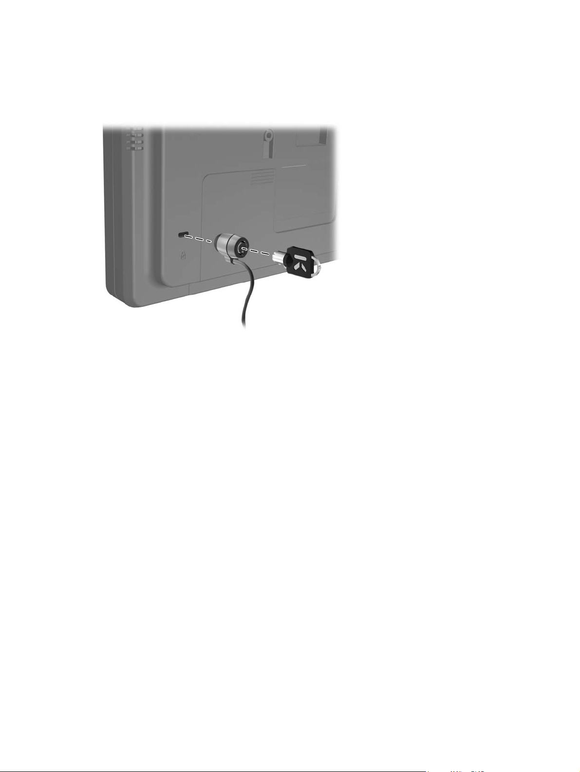
Installing a Cable Lock
You can secure the monitor to a fixed object with an optional cable lock available from HP.
Figure 2-30 Installing a Cable Lock
Locating the Rating Labels
The rating labels on the monitor provide the spare part number, product number, and serial number.
You may need these numbers when contacting HP about the monitor model. The rating labels are
located on the rear panel of the monitor display head.
18 Chapter 2 Setting Up the Monitor
Page 25
3 Operating the Monitor
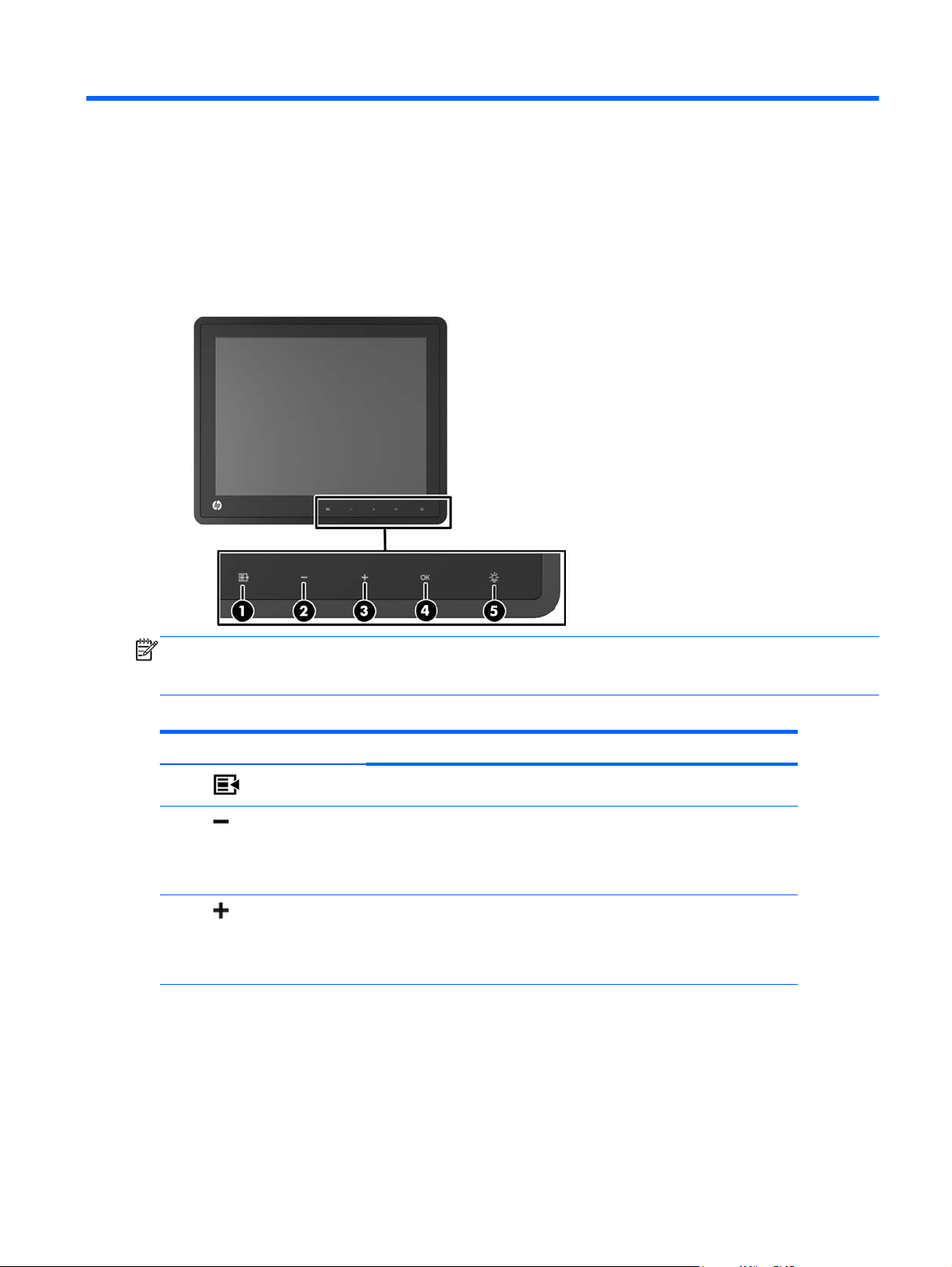
Front Panel Controls
Figure 3-1 Monitor Front Panel Controls
NOTE: The front panel controls are inactive unless they are illuminated. To activate the controls, tap
on the area where the icons are located. All icons will become illuminated and active. The backlight
for the icons will turn off upon exit from the OSD or when the OSD times out.
Table 3-1 Monitor Front Panel Controls
Control Function
1
2
3
Menu Opens the On-Screen Display (OSD) main menu.
– (Minus) If the OSD menu is on, tap to navigate backward through the OSD menu
and decrease adjustment levels.
If the OSD menu is inactive and the icons are illuminated, tap to open the
OSD volume control menu and adjust the volume level.
+ (Plus) If the OSD menu is on, tap to navigate forward through the OSD menu
and increase adjustment levels.
If the OSD menu is inactive and the icons are illuminated, tap to activate
the Source button that chooses the video signal input.
Front Panel Controls 19
Page 26

Table 3-1 Monitor Front Panel Controls (continued)
Control Function
4
5
OK If the OSD menu is on, tap to select a menu item.
If the OSD menu is inactive and the icons are illuminated, tap to activate
the auto adjustment feature to optimize the screen image.
Power LED Green = Fully powered.
Amber = Sleep mode.
Flashing Amber = Sleep Timer mode.
Off = Power is off or the LED has been suppressed in the OSD
NOTE: To view an OSD menu simulator, visit the HP Customer Self Repair Services Media Library
http://www.hp.com/go/sml.
at
Power Management System
The monitor is equipped with the power management function which automatically reduces the power
consumption when not in use.
Table 3-2 Power Management
Mode Power Consumption
Full Power 18 W
Typical Power 11 W
Sleep 1 W
Off 0.5 W
It is recommended that you switch the monitor off when it is not in use for a long period of time.
NOTE: The monitor automatically goes through the power management system steps when it is
idle. To release the monitor from the power management system, press any key on the keyboard or
move the mouse.
OSD Lock/Unlock
The OSD feature can be locked and unlocked. The monitor is shipped with the OSD menu in the
unlocked position.
To lock the OSD menu and disable the OSD controls, tap on the area where the OSD icons are
located so that the icons become illuminated and active, then press the Menu icon for 10 seconds. To
unlock the OSD menu and enable the OSD controls, press the Menu icon again for 10 seconds.
Power Button Lock/Unlock
The power button can be locked and unlocked. The monitor is shipped with the power button in the
unlocked position.
20 Chapter 3 Operating the Monitor
Page 27

To lock the power button, press the power button for 10 seconds. To unlock the power button, press
the power button again for 10 seconds. Unlocking the power button will power off the monitor. To
power it back on, press the power button.
Power Button Lock/Unlock 21
Page 28

4 Locating Additional Information
Refer to the HP LCD Monitors Reference Guide at http://www.hp.com/support for additional
information on:
Optimizing monitor performance
●
Safety and maintenance guidelines
●
Agency regulatory and environmental notices
●
Using the OSD menu
●
Downloading additional software from the Web for PC mode.
●
For additional information on using and adjusting your monitor, go to
Select your country or region, select Product Support & Troubleshooting, and then enter your monitor
model in the SEARCH window.
NOTE: The monitor user guide, reference guide, and drivers are available at http://www.hp.com/
support.
If the information provided in the guide or in the HP LCD Monitors Reference Guide do not address
your questions, you can contact support. For U.S. support, go to
For worldwide support, go to
Here you can:
Chat online with an HP technician
●
NOTE: When support chat is not available in a particular language, it is available in English.
E-mail support
●
Find support telephone numbers
●
Locate an HP service center
●
http://welcome.hp.com/country/us/en/wwcontact_us.html.
http://www.hp.com/support.
http://www.hp.com/go/contactHP.
22 Chapter 4 Locating Additional Information
Page 29

5 Technical Specifications
NOTE: All performance specifications are provided by the component manufacturers. Performance
specifications represent the highest specification of all HP's component manufacturers' typical level
specifications for performance and actual performance may vary either higher or lower.
HP L6010 Retail Monitor
Table 5-1 Specifications
LCD Display
Type
Pixel Pitch 0.0685 (H) x 0.2055 (V) mm 0.0027 (H) x 0.0081 (V) in
Horizontal Frequency 24 to 83 kHz
Vertical Frequency 50 to 76 Hz
Maximum Resolution 1024 x 768 at 75Hz
Aspect Ratio 4:3
Contrast Ratio 1000:1 (typical)
Brightness 300 nits (typical)
Response Time 25 ms (typical)
Color Gamut 57%
Viewing Angle (V/H at CR>10) 176 / 176
Video Sources VGA + DVI + DP
Front Controls Menu, Minus, Plus, OK, Power
OSD Main Menu Brightness, Contrast, Color, Image
26.4 cm
TFT LCD
Control, OSD Control, Management,
Language, Information, Factory Reset,
Source Control, Exit
10.4 inches
Power Input DC 12V, 2A, 24W
Operating Conditions
Temperature (Operating)
Temperature (Storage)
Humidity
Altitude
5° C to 40° C (41° F to 104° F)
-20°C to 60°C (-4°F to 140°F)
20% ~ 80% (No Condensation)
0 to 5000 meters (16,400 feet)
HP L6010 Retail Monitor 23
Page 30

Table 5-1 Specifications (continued)
Dimensions
Width
Height (with stand)
Height (without stand)
Depth (with stand)
Depth (without stand)
Weight
Actual (unpacked with stand)
Actual (unpacked without stand)
Shipping (packed without stand)
254.4 mm
235.9 mm
208.3 mm
167.9 mm
40.6 mm
2.6 kg
1.6 kg
4.3 kg
10.0 in
9.3 in
8.2 in
6.6 in
1.6 in
5.73 lb
3.53 lb
9.48 lb
24 Chapter 5 Technical Specifications
Page 31

Recognizing Preset Display Resolutions
The display resolutions listed below are the most commonly used modes and are set as factory
defaults. This monitor automatically recognized these preset modes and they will appear properly
sized and centered on the screen.
HP L6010 Retail Monitor
Table 5-2 Factory Preset Modes
Preset Pixel Format Horz Freq (kHz) Vert Freq (Hz)
1 640 × 480 31.469 59.940
2 720 × 400 31.469 70.087
3 800 × 600 37.879 60.317
4 1024 × 768 48.363 60.004
Entering User Modes
The video controller signal may occasionally call for a mode that is not preset if:
● You are not using a standard graphics adapter.
You are not using a preset mode.
●
If this occurs, you may need to readjust the parameters of the monitor screen by using the on-screen
display. Your changes can be made to any or all of these modes and saved in memory. The monitor
automatically stores the new setting, then recognizes the new mode just as it does a preset mode. In
addition to the 4 factory preset, there are 10 user modes that can be entered and stored.
Recognizing Preset Display Resolutions 25
Page 32

Energy Saver Feature
When the monitor is in its normal operating mode, the monitor uses less than 18 watts and the Power
light is green.
The monitor also supports a reduced power state. The reduced power state will be entered into if the
monitor detects the absence of either the horizontal sync signal and/or the vertical sync signal. Upon
detecting the absence of these signals, the monitor screen is blanked, the backlight is turned off, and
the power light is turned amber. When the monitor is in the reduced power state, the monitor will
utilize less than 1 watt of power. There is a brief warm up period before the monitor will return to its
normal operating mode.
Refer to the computer manual for instructions on setting energy saver features (sometimes called
power management features).
NOTE: The above power saver feature only works when connected to computers that have energy
saver features.
By selecting the settings in the monitor's Energy Saver utility, you can also program the monitor to
enter into the reduced power state at a predetermined time. When the monitor's Energy Saver utility
causes the monitor to enter the reduced power state, the power light blinks amber.
26 Chapter 5 Technical Specifications
 Loading...