


HP Designjet L25500 printer series
Site preparation guide (first edition)

Legal notices
© 2009 Hewlett-Packard Development
Company, L.P.
The information contained herein is subject
to change without notice.
The only warranties for HP Products and
services are set forth in the express warranty
statement accompanying such products and
services. Nothing herein should be
construed as constituting an additional
warranty. HP shall not be liable for technical
or editorial errors or omissions contained
herein.

Table of contents
1 Overview
Introduction ........................................................................................................................................... 1
Customer responsibility ........................................................................................................................ 1
Installation time schedule ..................................................................................................................... 1
2 Site preparation requirements
Physical space requirements ............................................................................................................... 2
Unloading route ................................................................................................................... 2
Fire fighting equipment ........................................................................................................ 3
Environmental specifications ............................................................................................... 3
Ventilation and air conditioning ............................................................................................ 3
RIP workstation characteristics ............................................................................................................ 4
Networking ........................................................................................................................................... 4
Printing supplies ................................................................................................................................... 4
Electrical configuration ......................................................................................................................... 4
Single phase power ............................................................................................................. 4
Circuit breakers .................................................................................................................... 5
Wall receptacles and power cords ....................................................................................... 5
Powerline disturbances ........................................................................................................................ 8
Grounding ............................................................................................................................................. 8
3 Site preparation checklist
ENWW iii

iv ENWW

1Overview
Introduction
This Site preparation guide should be used for HP Designjet L25500 printers, both 42 inch and 60 inch.
Specifications and requirements are stated for both printer widths wherever necessary.
Your printer is supplied ready to use after a few simple installation procedures described in detail in
the Assembly instructions. It is important to read the information provided in this guide thoroughly and
to ensure complete compliance with all installation and operation requirements, safety procedures,
warnings, cautions and local regulations. A well prepared site helps to provide a smooth and easy
installation.
Customer responsibility
Overview
You are responsible for all preparations of the physical site to install and place the printer:
Prepare the building's electrical system used to power the printer to meet the printer's requirements
●
and the Electrical Code requirements according to the local jurisdiction of the country where the
equipment is installed, and power up the printer on the day of installation. See
configuration on page 4.
NOTE: Make sure a certified electrician reviews the setup and configuration of the electrical
system used to power the printer. See
Meet temperature and humidity requirements and ensure proper ventilation for the printer. See
●
Environmental specifications on page 3.
Supply all necessary emergency equipment. See
●
Meet all RIP requirements, networking and printing supplies. See
●
characteristics on page 4, Networking on page 4 and Printing supplies on page 4.
Prepare the unloading route so the printer can be unloaded and maneuvered into place. See
●
Unloading route on page 2.
Installation time schedule
Allow a minimum of three hours for the installation. The installer may require the help of three people
to perform certain tasks during installation.
Electrical
Electrical configuration on page 4.
Fire fighting equipment on page 3.
RIP workstation
ENWW Introduction 1

2 Site preparation requirements
Requirements
Physical space requirements
Unloading route
The route between the unloading area of the printer and the installation site, including any corridors and
doorways through which the printer must be transported, is important to proper site preparation and
must be checked before the arrival of the printer. This pathway must be clear when the printer arrives.
Table 2-1 42-in printer physical specifications
Printer Packaging
Length 78 in (1.99 m) 87.79 in (2.23 m)
Width 27.5 in (0.69 m) 40.94 in (1.04 m)
Height 54 in (1.37 m) 47.64 in (1.21 m)
Weight 355 lb (161 kg) 550 lb (250 kg)
Table 2-2 60-in printer physical specifications
Printer Packaging
Length 97 in (2.47 m) 105.9 in (2.69 m)
Width 27.5 in (0.69 m) 40.94 in (0.81 m)
Height 54 in (1.37 m) 46.61 in (1.18 m)
Weight 399 lb (181 kg) 682 lb (310 kg)
Doorways: minimum width 40 in (1.01 m) x minimum height 66 in (1.67 m) required.
The space required for assembly is 10 ft (3 m) in front and 3.5 ft (1 m) at the sides and rear.
Most of the installation process requires one person, but four people are required to perform certain
tasks.
2 Chapter 2 Site preparation requirements ENWW

Fire fighting equipment
You must provide two fire extinguishers for the site. Make sure the extinguishers are placed where they
are easily accessible in case of fire.
A fire extinguisher certified for electrical fires must be in the print production area.
●
A fire extinguisher must be placed in the substrate storage area, due to the large amount of solid
●
combustibles (substrates).
Emergency exits and first aid stations should also be considered.
Environmental specifications
These environmental conditions must be kept within the specified ranges to ensure the correct operation
of the printer. Failure to do so may cause print-quality problems or damage sensitive electronic
components.
Table 2-3 Printer environmental specifications
Relative humidity range for best print quality 20–80%, depending on substrate type
Temperature range for best print quality 18 to 25°C (64 to 77°F), depending on substrate type
Temperature range for printing 15 to 30°C (59 to 86°F)
Temperature range when not in operation -25 to +55°C (-13 to +131°F)
Temperature gradient no more than 10°C/h (18°F/h)
Maximum altitude when printing 3000 m (10000 ft)
NOTE: The printer must be kept indoors.
NOTE: If the printer or ink cartridges are moved from a cold location to a warm and humid location,
water from the atmosphere can condensate on the printer parts and cartridges and can result in ink
leaks and printer errors. In this case, HP recommends that you wait at least 3 hours before turning on
the printer or installing the ink cartridges, to allow the condensate to evaporate.
In addition to controlling the temperature, humidity, and temperature gradient, there are other
environmental conditions that must be met during site preparation.
Do not install the printer where it will be exposed to direct sunlight or a strong light source.
●
Do not install the printer in a dusty environment. Remove any accumulated dust before moving the
●
printer into the area.
Requirements
Ventilation and air conditioning
The printer produces a significant amount of heat. Adequate ventilation and air conditioning is important
in the print production area.
Power dissipation (42-in printer: 3.5 Kw, 12.3 KBTU/h; 60-in printer: 4.8 Kw, 16.4 KBTU/h) and water
vapor from drying ink may require your site to have air conditioning. Adequate conditions can be
established by air renewal if the external temperature is cold enough.
It is recommended that positive airflow be maintained in the print production room. This will help prevent
dust from entering the room.
NOTE: The ventilation and air conditioning units should not blow air directly onto the printer.
ENWW Physical space requirements 3

Requirements
RIP workstation characteristics
The RIP computer and RIP software must be provided by the customer. Each RIP has specific
requirements. Check with your RIP vendor to find out the requirements for the PC that you'll be using
for the RIP station. Make sure that the RIP station is fully functional and ready for installation.
Networking
You are responsible for all networking requirements, and you must complete the following tasks:
NOTE: In order to perform remote support, the printer must have access to the Internet using the LAN
connection.
Have a Gigabit Ethernet network ready for the day of installation.
●
Provide a CAT-6 LAN cable to connect the printer to your LAN and RIP workstation.
●
Provide a Gigabit Ethernet switch.
●
Printing supplies
The following supplies should be purchased in addition to the printer and should be available on the day
of installation:
Six HP 789 ink cartridges, one for each color: black, cyan, magenta, yellow, light cyan and light
●
magenta.
At least one roll of substrate to perform calibrations and printhead alignment during printer setup.
●
Electrical configuration
NOTE: An electrician is required for the setup and configuration of the building electrical system used
to power the printer and also for printer installation. Make sure that your electrician is appropriately
certified according to local regulations and supplied with all the information regarding the electrical
configuration.
Your printer requires the following electrical components to be supplied and installed by the customer,
according to the Electrical Code requirements of the local jurisdiction of the country where the equipment
is installed.
Single phase power
Table 2-4 Single phase line specifications
60-in printer 42-in printer
Number of power cords 2 2
Input voltage 220-240 V~ (-10%+6%) 200-240 V~ (-10%+6%)
Input frequency 50 / 60 Hz 50 / 60 Hz
Power consumption 4.8 kW (overall consumption for both
power cords)
3.5 kW (overall consumption for both
power cords)
Maximum load current (per power cord) 15 A 13 A
4 Chapter 2 Site preparation requirements ENWW
WARNING! Ensure that the printer's built-in Residual Current Circuit Breaker (also known as Ground
Fault Circuit Interrupter) operates in the case of a leakage current fault to the product chassis, even
when an isolation device (such as an isolating transformer) is used to supply power to the printer.
CAUTION: Ensure that the input voltage is within the printer's rated voltage range. The 60-in printer
requires a step-up transformer for tri-phase 208 V or 200 V power systems (voltage line to line).
Circuit breakers
NOTE: The circuit breakers must meet the requirements of the printer and shall be in accordance with
the Electrical Code requirements of the local jurisdiction of the country where the equipment is installed.
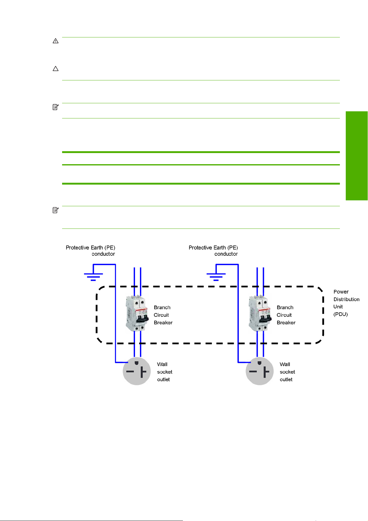
The printer requires two dedicated lines, each protected by a branch circuit breaker according to the
rating of the wall socket outlet.
Table 2-5 Circuit breaker specifications
Branch circuit breaker Quantity
Single phase line 2 poles, 16 A * (20A for NEMA 6-20R wall
1
* Rating according to wall socket outlet
socket)
1
2, one for each dedicated line
NOTE: The Power Distribution Unit (PDU) must be rated to meet the power requirements of the printer,
and shall be in accordance with the Electrical Code requirements of the local jurisdiction of the country
where the equipment is installed.
Figure 2-1 Electrical configuration diagram
Requirements
Wall receptacles and power cords
Two power cords are provided with your printer, according to the printer's electrical specifications. If
those cords do not reach your PDU and/or UPS, a certified electrician must install suitable extension
cables on the day of installation.
ENWW Electrical configuration 5

To make sure you have the right wall socket outlets (wall receptacles) ready for installation, check the
following:
Requirements
1. The wall socket outlets must be suitable for printer input ratings. See
Single phase power
on page 4.
2. The wall socket outlets must be suitable for the power cord plug type used in the country of
installation.
Table 2-6 60 inch printer power cord specifications on page 6 and Table 2-7 42 inch
printer power cord specifications on page 6 list several examples of the power cords and the
plugs provided with the printer according to the country. To make sure you have the right wall
receptacle, find your country in the appropriate table and check the plug type.
WARNING! Use only use the power cord supplied by HP with the printer. Do not use a power
strip (relocatable power tap) to connect both power cords. Do not damage, cut or repair the power
cord. With a damaged power cord, there is risk of fire and electric shock. Always replace a damaged
power cord with an HP-approved power cord.
Table 2-6 60 inch printer power cord specifications
Country HP Part Number * Length Plug type Plug
USA, Canada, Mexico,
Japan, Philippines,
Thailand
International 8120-6897 14.8 ft (4.5 m) IEC 60309, 240 V, 16
8120-6893 14.8 ft (4.5 m) NEMA 6-20P, 240 V,
20A, non-locking
A, 2L+PE
International – other 8120-6895 14.8 ft (4.5 m) Stripped end
termination, 240 V, 1.5
mm² cross sectional
area
WARNING! A
qualified electrician
must attach a suitable
plug according to local
laws where the printer
is installed, and to the
printer's electrical
requirements.
* Alternative part numbers are valid with the same specifications and markings.
Table 2-7 42 inch printer power cord specifications
Country HP Part Number * Length Plug type Plug
Argentina 8121-0925 8.2 feet (2.5 m) IRAM 2073
Brazil 8121-1101 8.2 feet (2.5 m) NBR 14136
Chile, Uruguay 8121-0923 8.2 feet (2.5 m) CEI 23-50
6 Chapter 2 Site preparation requirements ENWW

Table 2-7 42 inch printer power cord specifications (continued)
Country HP Part Number * Length Plug type Plug
USA, Canada, Mexico,
Philippines, Thailand,
Japan
Australia, New Zealand 8121-0871 14.8 feet (4.5 m) 3112-3, 15 A
China 8120-8934 8.2 feet (2.5 m) GB 1002
Continental Europe,
Korea, Indonesia,
Russia
India 8121-1074 8.2 feet (2.5 m) IS 1293
8120-6360 8.2 feet (2.5 m) NEMA 6-20P, 240 V,
20 A, non-locking
8120-6352 8.2 feet (2.5 m) CEE 7-VII
Requirements
Taiwan 8121-1033 14.8 feet (4.5 m) CNS 690
UK, Hong Kong,
Singapore
Denmark 8121-1077 8.2 feet (2.5 m) DK 2-5A
Israel 8121-1010 8.2 feet (2.5 m) SI 32
South Africa 8121-0915 8.2 feet (2.5 m) SABS 164
8121-0907 8.2 feet (2.5 m) BS 1363/A
Switzerland,
Liechtenstein
8120-6897 14.8 feet (4.5 m) IEC 60309, 240 V, 16
A, 2L+PE
ENWW Electrical configuration 7

* Alternative part numbers are valid with same specs and markings.
Table 2-8 Appliance coupler (printer connection)
Country Appliance coupler (power cable) Appliance coupler inlet (printer)
Requirements
All Detachable terminal as per IEC60320-1
NOTE: Place the wall receptacle close enough to the printer so the plug can be plugged and unplugged
easily.
Powerline disturbances
Reliable operation of your printer depends on the availability of relatively noise-free AC power.
In order to ensure optimum performance and reliability, your printer should be protected from
●
variations in line voltage. Lightning, line faults or the switching of lighting or machinery can generate
line transients that far exceed the peak value of the applied voltage. If not reduced, these
microsecond pulses can disrupt system operation and damage the printer.
It is recommended to include overvoltage (OVP) and transient protection in the power supply to
●
the printer.
C19 (squared type)
Detachable intlet as per IEC60320-1 C20
(squared type)
All electrical noise-generating equipment, such as fans, fluorescent lighting and air-conditioning
●
systems, should be kept separate from the power source used for your printer.
Grounding
The printer must be connected to a good-quality ground line in order to avoid electrical risk. Please note
your obligation to comply with the Electrical Code requirements of the local jurisdiction of the country
where the equipment is installed.
The following grounding tasks must be fulfilled to meet the site preparation requirements:
Grounding wires must be insulated and at least equal in size to the phase conductors.
●
Ground impedance must be less than 0.5 Ω.
●
8 Chapter 2 Site preparation requirements ENWW

3 Site preparation checklist
Safety requirements Yes No Comments
Is there an emergency exit in the print production area, with easy access and
free from any obstruction?
Have the two fire extinguishers been fitted in the prescribed locations in the
print production and storage areas? Is the print production fire extinguisher
rated for electrical fire?
Electrical installation requirements Yes No Comments
Is the electrician aware of all requirements and specifications highlighted in
this guide?
Is the single-phase line voltage inside the specified voltage range?
42-in printer: 200–240 V~ (–10%, +6%)
●
60-in printer: 220–240 V~ (–10%, +6%)
●
For the 60-in printer, the tri-phase 208 V or 200 V power systems (voltage
line-to-line) require a step-up transformer.
Are there two dedicated lines to connect the printer's two power cords?
NOTE: Do not use a power strip (relocatable power tap) to connect both
power cords.
Have branch circuit breakers (2 poles, 16 A general or 20 A for NEMA 6-20R
only) been correctly installed for each dedicated line?
(Required)
(Required)
Specify nominal mains voltage:
(Required)
(Required)
Checklist
Has the single-phase branch circuit breaker (2 poles, 20 A) been correctly
installed?
Is the Power Distribution Unit (PDU) correctly installed? (Required)
Are the grounding conductors properly installed for each wall receptacle (wall
socket)?
Are the wall receptacles (wall sockets) suitable for the power cord plug type
provided by HP?
Are the wall receptacles (wall sockets) and electrical installation suitable for
the printer's rated current ?
NOTE: The printer's rated current is 15 A for 60-in printers, and 13 A for
42-in printers.
(Required)
(Required)
(Required)
(Required)
ENWW 9

Electrical installation requirements Yes No Comments
Are the wall receptacles (wall sockets) placed close enough to the printer
that the plugs can be plugged and unplugged easily?
NOTE: The power cord length is 14.8 ft (4.5 m) for 60-in printers, and 8.2
ft (2.5 m) for 42-in printers.
Would the printer's built-in Residual Current Circuit Breaker (also known as
Ground Fault Circuit Interrupter) operate in the case of a current leakage fault
to the product chassis (even if an isolation device is installed)?
Electrical configuration requirements Yes No Comments
(Required)
(Required)
Checklist
Do you need an Uninterrupted Power Supply (UPS) or step-up transformer?
If so, is it correctly installed?
Networking and computer requirements Yes No Comments
Is the RIP computer and software ready for installation?
Have network connections been supplied?
Do you have a color sensor that is compatible with your RIP?
Do you have a LAN cable long enough to connect the printer to the network?
Environmental requirements Yes No Comments
Have the temperature and humidity requirements been satisfactorily met in
the print production area, and is there adequate ventilation or air
conditioning?
Have the temperature and humidity requirements been satisfactorily met in
the storage area?
Is the print production area free from dirt and dust?
Does the print production area have sufficient lighting?
Other requirements Yes No Comments
Have you arranged for supplies such as substrate and ink cartridges to be
available on the day of installation?
Have you met the requirements specified in this guide? (Required)
10 Chapter 3 Site preparation checklist ENWW
 Loading...